CN101864358B - Continuous solar biomass energy fermentation device - Google Patents
Continuous solar biomass energy fermentation device Download PDFInfo
- Publication number
- CN101864358B CN101864358B CN 201010197038 CN201010197038A CN101864358B CN 101864358 B CN101864358 B CN 101864358B CN 201010197038 CN201010197038 CN 201010197038 CN 201010197038 A CN201010197038 A CN 201010197038A CN 101864358 B CN101864358 B CN 101864358B
- Authority
- CN
- China
- Prior art keywords
- biomass energy
- fermentation device
- energy fermentation
- centrifugal
- weight
- Prior art date
- Legal status (The legal status is an assumption and is not a legal conclusion. Google has not performed a legal analysis and makes no representation as to the accuracy of the status listed.)
- Expired - Fee Related
Links
Images


Classifications
-
- C—CHEMISTRY; METALLURGY
- C12—BIOCHEMISTRY; BEER; SPIRITS; WINE; VINEGAR; MICROBIOLOGY; ENZYMOLOGY; MUTATION OR GENETIC ENGINEERING
- C12M—APPARATUS FOR ENZYMOLOGY OR MICROBIOLOGY; APPARATUS FOR CULTURING MICROORGANISMS FOR PRODUCING BIOMASS, FOR GROWING CELLS OR FOR OBTAINING FERMENTATION OR METABOLIC PRODUCTS, i.e. BIOREACTORS OR FERMENTERS
- C12M47/00—Means for after-treatment of the produced biomass or of the fermentation or metabolic products, e.g. storage of biomass
- C12M47/10—Separation or concentration of fermentation products
-
- C—CHEMISTRY; METALLURGY
- C12—BIOCHEMISTRY; BEER; SPIRITS; WINE; VINEGAR; MICROBIOLOGY; ENZYMOLOGY; MUTATION OR GENETIC ENGINEERING
- C12M—APPARATUS FOR ENZYMOLOGY OR MICROBIOLOGY; APPARATUS FOR CULTURING MICROORGANISMS FOR PRODUCING BIOMASS, FOR GROWING CELLS OR FOR OBTAINING FERMENTATION OR METABOLIC PRODUCTS, i.e. BIOREACTORS OR FERMENTERS
- C12M23/00—Constructional details, e.g. recesses, hinges
- C12M23/38—Caps; Covers; Plugs; Pouring means
-
- C—CHEMISTRY; METALLURGY
- C12—BIOCHEMISTRY; BEER; SPIRITS; WINE; VINEGAR; MICROBIOLOGY; ENZYMOLOGY; MUTATION OR GENETIC ENGINEERING
- C12M—APPARATUS FOR ENZYMOLOGY OR MICROBIOLOGY; APPARATUS FOR CULTURING MICROORGANISMS FOR PRODUCING BIOMASS, FOR GROWING CELLS OR FOR OBTAINING FERMENTATION OR METABOLIC PRODUCTS, i.e. BIOREACTORS OR FERMENTERS
- C12M27/00—Means for mixing, agitating or circulating fluids in the vessel
- C12M27/02—Stirrer or mobile mixing elements
-
- C—CHEMISTRY; METALLURGY
- C12—BIOCHEMISTRY; BEER; SPIRITS; WINE; VINEGAR; MICROBIOLOGY; ENZYMOLOGY; MUTATION OR GENETIC ENGINEERING
- C12M—APPARATUS FOR ENZYMOLOGY OR MICROBIOLOGY; APPARATUS FOR CULTURING MICROORGANISMS FOR PRODUCING BIOMASS, FOR GROWING CELLS OR FOR OBTAINING FERMENTATION OR METABOLIC PRODUCTS, i.e. BIOREACTORS OR FERMENTERS
- C12M33/00—Means for introduction, transport, positioning, extraction, harvesting, peeling or sampling of biological material in or from the apparatus
- C12M33/10—Means for introduction, transport, positioning, extraction, harvesting, peeling or sampling of biological material in or from the apparatus by centrifugation ; Cyclones
-
- C—CHEMISTRY; METALLURGY
- C12—BIOCHEMISTRY; BEER; SPIRITS; WINE; VINEGAR; MICROBIOLOGY; ENZYMOLOGY; MUTATION OR GENETIC ENGINEERING
- C12M—APPARATUS FOR ENZYMOLOGY OR MICROBIOLOGY; APPARATUS FOR CULTURING MICROORGANISMS FOR PRODUCING BIOMASS, FOR GROWING CELLS OR FOR OBTAINING FERMENTATION OR METABOLIC PRODUCTS, i.e. BIOREACTORS OR FERMENTERS
- C12M33/00—Means for introduction, transport, positioning, extraction, harvesting, peeling or sampling of biological material in or from the apparatus
- C12M33/22—Settling tanks; Sedimentation by gravity
Landscapes
- Life Sciences & Earth Sciences (AREA)
- Health & Medical Sciences (AREA)
- Engineering & Computer Science (AREA)
- Organic Chemistry (AREA)
- Zoology (AREA)
- Bioinformatics & Cheminformatics (AREA)
- Chemical & Material Sciences (AREA)
- Wood Science & Technology (AREA)
- Biotechnology (AREA)
- General Engineering & Computer Science (AREA)
- Sustainable Development (AREA)
- Biochemistry (AREA)
- Biomedical Technology (AREA)
- General Health & Medical Sciences (AREA)
- Genetics & Genomics (AREA)
- Microbiology (AREA)
- Molecular Biology (AREA)
- Clinical Laboratory Science (AREA)
- Treatment Of Sludge (AREA)
- Apparatus Associated With Microorganisms And Enzymes (AREA)
Abstract
The invention discloses a continuous solar biomass energy fermentation device, comprising a biomass energy fermentation device, a weight lifting device and a solid-liquid separating device, wherein the top part of the biomass energy fermentation device is provided with a feeding inlet (3) and a gas guiding pipe (4), and the bottom part thereof is provided with a discharging outlet (19); the discharging outlet (19) is connected with a feeding inlet (20) of the solid-liquid separating device; and the feeding inlet (20) of the solid-liquid separating device is connected to a centrifugal cavity (21) which is internally provided with a drawing net (26) and is provided with a centrifugal discharging outlet (22), a centrifugal slag hole (24) and a centrifugal liquid outlet (25). The continuous solar biomass energy fermentation device solves the problems that the traditional biomass energy fermentation device cannot keep constant temperature, has low gas yield, can not carry out continuous feeding, has difficult and dangerous discharging, is not thorough for separation of biogas fluid and biogas slag, can realize effective utilization, is easy to crust and deposit and the like and has very wide application prospect.
Description
Technical field
the present invention relates to a kind of biogas generating device, and particularly a kind of continuous solar biomass energy fermentation device belongs to biogas production device technique field.
Background technology
biogas is a kind of renewable energy source of cleaning, and developed country just began one's study and utilizes biogas from the thirties in 20th century.In recent years, developed country mainly from the protection environment, has set up a lot of biogas engineerings, and the biogas production technology is comparative maturity.Biogas production is progressively integrated, mass-producing, changes present large-scale centralized production gradually into from original small apartment production model.In recent years, the biogas cause of China has obtained development rapidly.Particularly in the Rural areas, biogas energy distributes extensively.Produce biogas, can make the treating processes of organic wastes such as ight soil, stalk reach pollution-free, thereby the conservation of nature environment can also solve the fuel and the lighting problem in rural area, save energy.Under the call of the new rural policy of nation-building, the development and utilization of China's production and use of marsh gas energy has a extensive future.
are present; Biomass energy fermentation device is used at family, known rural area; Majority is to adopt brick and concrete to build the pond underground digging pit, and exists to build the pond difficulty of digging pit, build the pond quality standard uneven, can not continuous charging, many drawbacks such as discharging management difficulty and factor of created gase be low.Structurally, traditional biomass energy fermentation device is made up of feed space, sweathouse and discharge room, and its top is a little more than ground.The feed space of this biomass energy fermentation device and discharge room are positioned at the both sides of sweathouse; Not only floor space is big, and input and output material is inconvenient, and heat insulation effect is also not ideal; And all biomass energy fermentation devices all do not have whipping appts basically, and natural pond liquid surface is crust easily.In recent years, second buried spherical biogas jar of some regional WKG working glass reinforced plastic ground also fails to solve the difficult problem of discharging.
Summary of the invention
technical problem to be solved by this invention is to provide a kind of discharging and discharging continuous solar biomass energy fermentation device easily, thereby overcomes the deficiency of prior art.
are for solving the problems of the technologies described above technical scheme of the present invention: continuous solar biomass energy fermentation device.Comprise biomass energy fermentation device, weight lifting gear and equipment for separating liquid from solid, be provided with opening for feed and gas tube at the top of biomass energy fermentation device, the bottom is provided with discharge port; Discharge port connects the opening for feed of equipment for separating liquid from solid, and the opening for feed of equipment for separating liquid from solid is connected to centrifugal chamber, and the pull net is housed in centrifugal chamber, and the pull net is contained on the bearing, and bearing connects manual lever; On centrifugal chamber, be provided with centrifugal discharge mouth, centrifugal slag notch and centrifugal liquid outlet.
above-mentioned continuous solar biomass energy fermentation device, described weight lifting gear comprise that weight promotes operating stick, weight lifting rod and weight; Weight promotes the top that operating stick is connected the weight lifting rod, and weight is connected the bottom of weight lifting rod, and weight is placed in the discharge port of biomass energy fermentation device, blocks discharge port.
aforesaid continuous solar biomass energy fermentation device; In described biomass energy fermentation device, hand mixer is housed; Fan is stirred on the top of this whisking appliance and bottom stirring fan is installed on the carrier bar of hollow; Carrier bar is placed in weight lifting rod outside, in the end of carrier bar the mixer operations bar is housed.
aforesaid continuous solar biomass energy fermentation device, described bearing are to connect manual lever through gear; Manual lever connects the liquid lifter through belt; Natural pond liquid circulation tube is housed on the liquid lifter, and an end of natural pond liquid circulation tube connects the centrifugal liquid outlet of equipment for separating liquid from solid, and the other end is connected to the opening for feed of biomass energy fermentation device.
aforesaid continuous solar biomass energy fermentation device; The top of said biomass energy fermentation device is double-deck hollow design; In the upper case of biomass energy fermentation device and the cavity between the inner casing, sealing water is housed; On the top of biomass energy fermentation device floating cover is housed, the bottom of floating cover places sealing water.
aforesaid continuous solar biomass energy fermentation device; The bottom of said biomass energy fermentation device is double-deck hollow design; In the lower case of biomass energy fermentation device and the cavity between the inner casing, be equipped with and add hot water, built-in annular electro heating rod; The power interface of electrically heated rod is connected to the wire jack of sun power temperature controlling system through lead; Wire jack connects X-former, and X-former connects solar panel.
aforesaid continuous solar biomass energy fermentation device, described biomass energy fermentation device is the cylinder taper, its cylinder and circular cone interface are airflow design.
beneficial effect of the present invention: compared with prior art, the present invention is mainly used in rural area small apartment and urban cells production, solves traditional biological mass-energy fermentation unit and can not keep constant temperature; Factor of created gase is low; Can not continuous charging, discharging difficulty and dangerous, liquid natural pond, natural pond slag separates not thorough; Can not reach effective utilization, be prone to problems such as crust, deposition in the reaction process.The major technique that the present invention adopts has: the constant-temperature solar technology, guarantee the biogas fermentation homo(io)thermism, and improve the time in biogas yield and aerogenesis season; Adopt cover-floating type biomass energy fermentation device lid, reach the gastight purpose of continuous charging; Adopt cylinder cone biomass energy fermentation device (cylinder and circular cone interface adopt airflow design) one design and the discharging of weight lifting gear to overcome the discharging difficult problem; The weight lifting system of blocking up is set realizes unpowered operation; Hand mixer is set, guarantees that material stirs and can realize broken shell; Centrifugal pull net solid-liquid separator and manual liquid lifter are set reach solid-liquid separation, continuous discharge and natural pond liquid recycle.In order to guarantee that the methane-generating pit temperature keeps constant, the present invention adopts the solar constant temperature heating system.Solar panel mainly is made up of five parts: luminous energy is converted into the photovoltaic module of electric energy, and solar cell is controlled the unit of rechargeable solar battery amount and discharge capacity, miniature transformer in addition.Photovoltaic module is the absorb light photograph by day, is that electrical power storage is in solar cell with conversion of solar energy.When general fine, under the ideal intensity of illumination, be full of electricity as long as 4 hours, can guarantee at most more than 5 days after each charging is accomplished, but overcast and rainy 3 days also works better continuously.Also allomeric pipe is the same for solar panel, is made up of semi-conductor.Its main raw is a silicon, and some other alloys are also arranged.When needing electricity consumption, the electric energy in the solar panel becomes 220V through small transformers.Double-deck hollow design is adopted in the biomass energy fermentation device bottom, fills water in middle part, the in-built electrical heating rod.Cross when low when the biomass energy fermentation device interior reaction temperature, electrically heated rod and solar cell are linked up and can heat, be heated to certain temperature, pull out latch and get final product with the latch line.In order to solve continuous charging and anti-gas-leak problem, the present invention adopts the cover-floating type methane tank cover, and this methane tank cover is easy for removal and installation, directly gets into the reaction tank middle part by inlet when material is reinforced, and can not leak gas in the reinforced process.In order to solve methane-generating pit discharging continuous problem; The upper and lower part interface adopts airflow design, utilizes the weight up-down system of blocking up to control the methane-generating pit discharging, and the weight maximum diameter is a bit larger tham the discharge port diameter; Its principle of work is as scheming: the when filling with substance weight falls, and blocks discharge port.Weight utilizes the rigidity pull-up, inapplicable other power-equipments in the process that promptly promotes.The natural pond slag will be discharged by discharge port in the self-gravity action lower edge.For thorough mixing, in the movement weight rod outside manual type whisking appliance is set, operating stick is placed on body top, pond, and a pair of agitating vane is established in the bottom.In order to solve solid-liquid separation and liquid circulation utilizes problem, the present invention adopts centrifugal solid-liquid separator and manual liquid lifter.Separate natural pond liquid with the natural pond slag through centrifugation, natural pond liquid is extracted into methane-generating pit top through manual drawing liquid body lifter, supplies recycle.
Transformation Application prospect of the present invention: China is an agriculture prodn big country, and the raw material sources of making biogas are abundant.Biogas is just progressively widened the great development scale as a kind of novel clean energy, replaces Nonrenewable energy resources such as coal.Therefore biogas production will progressively grow up.Present domestic small-sized methane production unit kind is single, and has drawbacks such as input and output material management difficulty, temperature control difficulty, energy consumption height.And aerogenesis continuously, after the fermentation of having installed one-period, need about 20 days discharging with add the material time, approximately need stop the supple of gas or steam about one month after aerogenesis is steady.Bring very big difficulty for the continuous application of biogas, so a kind of energy consumption of market in urgent need is low, the input and output material management is convenient, can keep the homothermic methane-generating pit.It is air tight continuously to the invention solves input and output material, aerogenesis successive problem, and easy for operation, and simplicity of design, advantage such as development cost are low, therefore, application prospect is boundless.
Description of drawings
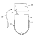
Fig. 1 is a structure principle chart of the present invention;
Fig. 2 is the work synoptic diagram of sun power temperature controlling system;
Fig. 3 is a floating cover structure synoptic diagram of the present invention;
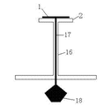
Fig. 4 is weight lifting gear of the present invention and hand mixer fundamental diagram;
Fig. 5 is equipment for separating liquid from solid of the present invention and liquid lifter fundamental diagram.
are further described the present invention below in conjunction with accompanying drawing and embodiment.
Embodiment
embodiment.As shown in Figure 1, comprise biomass energy fermentation device, weight lifting gear and equipment for separating liquid from solid.Biomass energy fermentation device is mainly used in the continuous aerogenesis of small apartment, can be embedded on the earth steps, also can use stationary installation (as laying bricks, do support etc.) to be fixed in ground.The main part of biomass energy fermentation device is the transparent hard plastic cylindrical shell, is provided with opening for feed 3 and gas tube 4 at its top, and the bottom is provided with discharge port 19; Discharge port 19 connects the opening for feed 20 of equipment for separating liquid from solid; The opening for feed 20 of equipment for separating liquid from solid is connected to centrifugal chamber 21; In centrifugal chamber 21, pull net 26 is housed, pull net 26 is contained on the bearing 29, and bearing 29 connects manual lever 28 through the gear 23 of pair of meshing; Manual lever 28 is installed in the master wheel center and connects liquid lifter 31 through belt 30; Shake manual lever 28 with regard to available less power like this; Make the bearing of solid-liquid separator reach high rotational speed; With higher efficient separate solid and liquid, drive 31 operations of liquid lifter simultaneously.Natural pond liquid circulation tube 32 is housed on liquid lifter 31, and an end of natural pond liquid circulation tube 32 connects the centrifugal liquid outlet 25 of equipment for separating liquid from solid, and the other end is connected to the opening for feed 3 of biomass energy fermentation device.On centrifugal chamber 21, be provided with centrifugal discharge mouth 22, centrifugal slag notch 24 and centrifugal liquid outlet 25.The solidliquid mixture that from biomass energy fermentation device, comes out is got into the centrifugal chamber 21 of solid-liquid separator by opening for feed 20; Through shaking manual lever 28 pull net 26 and bearing 29 are rotated, produce cf-, material gets into hollow bearing 29 backs and under centrifugal action, overflows from centrifugal discharge mouth 22; The solidliquid mixture that overflows is under stirring action; Solid comes out from centrifugal slag notch 24 under the promotion of spiral lamination, connects slag box 27 dress slags with packaged type, and liquid then flows to centrifugal liquid outlet 25.Liquid lifter 31 links to each other with manual lever 28 through belt 30, and when shaking manual lever 28 and carry out solid-liquid separation, liquid is promoted to reaction unit top, directly passes through natural pond liquid circulation tube 32 inflow biomass energy fermentation devices, reaches recycle.The weight lifting gear comprises that weight promotes operating stick 1, weight lifting rod 17 and weight 18; Weight promotes the top that operating stick 1 is connected weight lifting rod 17, and weight 18 is connected the bottom of weight lifting rod 17, and weight 18 is placed in the discharge port 19 of biomass energy fermentation device, and weight 18 maximum diameters are a bit larger tham discharge port 19 diameters, block discharge port 19.Hand mixer is housed in biomass energy fermentation device; The top of this whisking appliance is stirred fan 12 and is adopted rigid material with bottom stirring fan 13; Be installed on the carrier bar 16 of hollow, carrier bar 16 is placed in weight lifting rod 17 outsides, in the end of carrier bar 16 mixer operations bar 2 is housed.Through the promptly rotatable agitating vane of hand mixer operations bar 2, reach mixing effect.Its middle and upper part is stirred fan 12 and is mainly stirred with top, prevents reaction unit top crust.The bottom is stirred fan 13 and is mainly used in the bottom stirring, prevents the reaction mass deposition.For guaranteeing that continuously feeding prevents gas leakage; The top of biomass energy fermentation device is double-deck hollow design; Sealing water 6 is housed in the upper case 7 of biomass energy fermentation device and the cavity between the inner casing 8; On the top of biomass energy fermentation device floating cover 5 is housed, the bottom of floating cover 5 places sealing water 6.During charging, open the lid of opening for feed 20 through open-and-shut controller 37, material directly gets in the middle part of the reaction unit through opening for feed 20.During not charging, close opening for feed 20 through open-and-shut controller 37, the biogas of generation is discharged through gas tube 4, and gas tube 4 inserts biomass energy fermentation device top by passage.The bottom of biomass energy fermentation device is double-deck hollow design, in the lower case 10 of biomass energy fermentation device and the cavity between the inner casing 8, is equipped with to add hot water 11, built-in annular electro heating rod 14; The power interface 15 of electrically heated rod 14 is connected to the wire jack 36 of sun power temperature controlling system through lead 35; Wire jack 36 connects X-former 34, and X-former 34 connects solar panel 33.Biomass energy fermentation device is a cylinder taper integral type, and its cylinder and circular cone interface are airflow design, are convenient to discharging.The formation of sun power temperature controlling system is as shown in Figure 2, and solar panel 33 absorbs sun power and converts electric energy into and preservation, and when needing electricity consumption, the electricity in the solar panel 33 can be converted into the 220V electric energy through miniature transformer 34.When the biomass energy fermentation device temperature is low, connect the power interface jack 15 of electrically heated rod 14 and the wire jack 36 of sun power temperature controlling system with latch line 35; Can heat for the hot water 11 that adds in the biomass energy fermentation device shell; Then conduct heat and give biomass energy fermentation device internal reaction thing, guarantee constant temperature.The present invention is provided with the weight lifting gear, can ensure to make things convenient for charging and discharging, can realize unpoweredly again, and promptly weight can not use other power-equipments in lifting process.Its principle of work is as shown in Figure 4, and weight 18 is through weight lifting rod 17 rising and falling at charging and discharging time control weight.Weight lifting rod 17 adopts rigid material, when liquid buoyancy is big, can press downwards through manpower.When charging and reaction, block the discharge port 19 of biomass energy fermentation device by weight 18.During discharging, promote operating stick 1 by weight and mention weight 18, material just can be flowed out by discharge port 19, and flows into equipment for separating liquid from solid.
principle of work: material drops into from opening for feed 3, gets into biomass energy fermentation device and begins reaction.When filling with substance weight 18 falls under the control of weight lifting operating stick 1, blocks discharge port 19.The biogas that produces enters outside biogas storage device along gas tube 4.In the process of reaction; If temperature is lower than set(ting)value; Couple together the power interface 15 of the wire jack 36 of sun power temperature controlling system and electrically heated rod 14 with lead 35; The electric energy that produces through sun power is to add hot water 11 heating in the biomass energy fermentation device, reaches certain temperature, pulls out the latch line and gets final product.Utilize weight to promote operating stick 1 pull-up weight 18 after question response is complete, the natural pond slag will be discharged by discharge port 19 in the self-gravity action lower edge.So just solved the discharging difficulty and can not keep two problems of constant temperature.Shake manual lever 28, separate the mixture that gets into centrifugal solid-liquid separator from opening for feed 20, drive 31 runnings of liquid lifter simultaneously, natural pond liquid is got in the biomass energy fermentation device through natural pond liquid circulation tube 32 again, reach recycle.
embodiment of the present invention is not limited to the foregoing description, and the various variations of under the prerequisite that does not break away from aim of the present invention, making all belong within protection scope of the present invention.
Claims (4)
1. continuous solar biomass energy fermentation device; Comprise biomass energy fermentation device, weight lifting gear and equipment for separating liquid from solid; It is characterized in that: be provided with opening for feed (3) and gas tube (4) at the top of biomass energy fermentation device, the bottom is provided with discharge port (19); Discharge port (19) connects the opening for feed (20) of equipment for separating liquid from solid; The opening for feed of equipment for separating liquid from solid (20) is connected to centrifugal chamber (21); Pull net (26) is housed in centrifugal chamber (21); Pull net (26) is contained on the bearing (29), and bearing (29) connects manual lever (28); On centrifugal chamber (21), be provided with centrifugal discharge mouth (22), centrifugal slag notch (24) and centrifugal liquid outlet (25); Described weight lifting gear comprises that weight promotes operating stick (1), weight lifting rod (17) and weight (18); Weight promotes the top that operating stick (1) is connected weight lifting rod (17), and weight (18) is connected the bottom of weight lifting rod (17), and weight (18) is placed in the discharge port (19) of biomass energy fermentation device, blocks discharge port (19); The top of described biomass energy fermentation device is double-deck hollow design; Sealing water (6) is housed in the upper case (7) of biomass energy fermentation device and the cavity between the inner casing (8); Floating cover (5) is housed on the top of biomass energy fermentation device, and the bottom of floating cover (5) places sealing water (6); The bottom of said biomass energy fermentation device is double-deck hollow design, in the lower case (10) of biomass energy fermentation device and the cavity between the inner casing (8), is equipped with to add hot water (11), built-in annular electro heating rod (14); The power interface (15) of electrically heated rod (14) is connected to the wire jack (36) of sun power temperature controlling system through lead (35); Wire jack (36) connects X-former (34), and X-former (34) connects solar panel (33).
2. continuous solar biomass energy fermentation device according to claim 1; It is characterized in that: in described biomass energy fermentation device, hand mixer is housed; Fan (12) is stirred on the top of this whisking appliance and bottom stirring fan (13) is installed on the carrier bar (16) of hollow; Carrier bar (16) is placed in weight lifting rod (17) outside, in the end of carrier bar (16) mixer operations bar (2) is housed.
3. continuous solar biomass energy fermentation device according to claim 1 is characterized in that: described bearing (29) connects manual lever (28) through gear (23); Manual lever (28) connects liquid lifter (31) through belt (30); Natural pond liquid circulation tube (32) is housed on liquid lifter (31), and an end of natural pond liquid circulation tube (32) connects the centrifugal liquid outlet (25) of equipment for separating liquid from solid, and the other end is connected to the opening for feed (3) of biomass energy fermentation device.
4. continuous solar biomass energy fermentation device according to claim 1 is characterized in that: described biomass energy fermentation device is the cylinder taper, and its cylinder and circular cone interface are airflow design.
Priority Applications (1)
| Application Number | Priority Date | Filing Date | Title |
|---|---|---|---|
| CN 201010197038 CN101864358B (en) | 2010-06-10 | 2010-06-10 | Continuous solar biomass energy fermentation device |
Applications Claiming Priority (1)
| Application Number | Priority Date | Filing Date | Title |
|---|---|---|---|
| CN 201010197038 CN101864358B (en) | 2010-06-10 | 2010-06-10 | Continuous solar biomass energy fermentation device |
Publications (2)
| Publication Number | Publication Date |
|---|---|
| CN101864358A CN101864358A (en) | 2010-10-20 |
| CN101864358B true CN101864358B (en) | 2012-07-25 |
Family
ID=42956285
Family Applications (1)
| Application Number | Title | Priority Date | Filing Date |
|---|---|---|---|
| CN 201010197038 Expired - Fee Related CN101864358B (en) | 2010-06-10 | 2010-06-10 | Continuous solar biomass energy fermentation device |
Country Status (1)
| Country | Link |
|---|---|
| CN (1) | CN101864358B (en) |
Families Citing this family (6)
| Publication number | Priority date | Publication date | Assignee | Title |
|---|---|---|---|---|
| CN104355720A (en) * | 2014-12-03 | 2015-02-18 | 东北农业大学 | Movable portable solid fermentation device |
| CN104355721B (en) * | 2014-12-03 | 2017-04-26 | 东北农业大学 | Energy-saving type solid continuous fermentation device |
| CN105602841B (en) * | 2016-01-11 | 2018-07-27 | 吉林化工学院 | A kind of biomass is continuously fermented system |
| CN108130257B (en) * | 2018-03-08 | 2024-03-12 | 江苏辉强新能源科技有限公司 | Full-automatic multifunctional solar photovoltaic brewing machine |
| CN109020658B (en) * | 2018-07-26 | 2019-10-18 | 陈桂芬 | A kind of Solid Waste Treatment pond |
| CN114907952A (en) * | 2022-05-18 | 2022-08-16 | 安徽德鑫源食品有限公司 | Intelligent fermentation equipment for continuous grain processing and grain fermentation process |
Citations (7)
| Publication number | Priority date | Publication date | Assignee | Title |
|---|---|---|---|---|
| CN1480523A (en) * | 2002-09-03 | 2004-03-10 | 黄熙瑜 | Fermenting tank for treating garbage |
| CN2755086Y (en) * | 2004-12-28 | 2006-02-01 | 李建锋 | Self-mixing solar methane tank |
| CN1974752A (en) * | 2006-12-13 | 2007-06-06 | 辽宁省农业科学院生命科学中心 | Infegrated double cavity marsh gas fermenting system |
| EP1795584A1 (en) * | 2005-12-10 | 2007-06-13 | U.T.S. Umwelt-Technik-Süd GmbH | A one-step process of a flow wet-fermentation in a biogas digester |
| CN200946148Y (en) * | 2005-05-14 | 2007-09-12 | 康恒德 | Solar energy middle-high temperature marsh gas pour |
| WO2009016082A2 (en) * | 2007-07-30 | 2009-02-05 | Fraunhofer-Gesellschaft zur Förderung der angewandten Forschung e.V. | Method for the conversion of biomass from renewable raw materials in anaerobic fermenters |
| CN201704332U (en) * | 2010-06-10 | 2011-01-12 | 贵州大学 | Continuous solar energy and biomass energy fermentation device for small apartments |
-
2010
- 2010-06-10 CN CN 201010197038 patent/CN101864358B/en not_active Expired - Fee Related
Patent Citations (7)
| Publication number | Priority date | Publication date | Assignee | Title |
|---|---|---|---|---|
| CN1480523A (en) * | 2002-09-03 | 2004-03-10 | 黄熙瑜 | Fermenting tank for treating garbage |
| CN2755086Y (en) * | 2004-12-28 | 2006-02-01 | 李建锋 | Self-mixing solar methane tank |
| CN200946148Y (en) * | 2005-05-14 | 2007-09-12 | 康恒德 | Solar energy middle-high temperature marsh gas pour |
| EP1795584A1 (en) * | 2005-12-10 | 2007-06-13 | U.T.S. Umwelt-Technik-Süd GmbH | A one-step process of a flow wet-fermentation in a biogas digester |
| CN1974752A (en) * | 2006-12-13 | 2007-06-06 | 辽宁省农业科学院生命科学中心 | Infegrated double cavity marsh gas fermenting system |
| WO2009016082A2 (en) * | 2007-07-30 | 2009-02-05 | Fraunhofer-Gesellschaft zur Förderung der angewandten Forschung e.V. | Method for the conversion of biomass from renewable raw materials in anaerobic fermenters |
| CN201704332U (en) * | 2010-06-10 | 2011-01-12 | 贵州大学 | Continuous solar energy and biomass energy fermentation device for small apartments |
Non-Patent Citations (2)
| Title |
|---|
| 李志文等.有机废弃物厌氧消化产沼气技术研究进展.《贵州化工》.2009,第34卷(第5期),18-21. * |
| 李志文等.稻草秸秆厌氧发酵产沼气的工艺参数优化.《广州化工》.2010,第38卷(第4期),93-95,117. * |
Also Published As
| Publication number | Publication date |
|---|---|
| CN101864358A (en) | 2010-10-20 |
Similar Documents
| Publication | Publication Date | Title |
|---|---|---|
| CN101864358B (en) | Continuous solar biomass energy fermentation device | |
| CN204550537U (en) | A kind of complete mixed biogas production system | |
| CN201704332U (en) | Continuous solar energy and biomass energy fermentation device for small apartments | |
| CN103964903B (en) | Anaerobic and aerobic fermentation coupling device for organic garbage treatment | |
| CN104762201A (en) | CSTR fermentation device-based methane recycling system | |
| CN109896873A (en) | Utilize the composting device for domestic waste and its method of wind energy temperature raising | |
| CN103602581B (en) | Multistage stirring solar-assisted heating energy-saving fermentation device | |
| CN105349415A (en) | Solar- and wind-driven generating synergism system of methane tank | |
| CN101886036A (en) | Full-ecological, intelligent and multifunctional environmental protection methane generator | |
| CN203582851U (en) | Energy-saving biogas fermentation tank | |
| CN205115486U (en) | Energy -concerving and environment -protective methane -generating pit increase system | |
| CN205501313U (en) | Organic rubbish dry -type anaerobic fermentation device | |
| CN107523480A (en) | A kind of solar energy auxiliary heating type biogas quick reaction device | |
| CN201817491U (en) | Synergy device of solar photoelectrical generation system applied to methane pool | |
| CN105199952A (en) | Biogas digester synergistic system | |
| CN201762225U (en) | Full-ecological intelligent and multifunctional environment-friendly biogas generator | |
| CN202197231U (en) | Methane-photovoltaic complementation combined energy system | |
| CN101624565B (en) | Preparation of methane reactor | |
| CN108165474A (en) | Integrated city bionethanation system | |
| CN104805002A (en) | Resourceful treatment system adopting straw to produce biogas and having efficient anaerobic fermentation function | |
| CN204689992U (en) | A kind of anti-crusting marsh gas tank | |
| CN109422410A (en) | A kind of processing method of biogas slurry | |
| CN2616533Y (en) | Grow-culture joint ecological methane-generating pit | |
| CN202539174U (en) | Garbage treatment device | |
| CN201915014U (en) | Methane generator |
Legal Events
| Date | Code | Title | Description |
|---|---|---|---|
| C06 | Publication | ||
| PB01 | Publication | ||
| C10 | Entry into substantive examination | ||
| SE01 | Entry into force of request for substantive examination | ||
| C14 | Grant of patent or utility model | ||
| GR01 | Patent grant | ||
| CF01 | Termination of patent right due to non-payment of annual fee | ||
| CF01 | Termination of patent right due to non-payment of annual fee |
Granted publication date: 20120725 Termination date: 20200610 |