CN101825646A - Device and method for measuring flow rate of thin water flow by electrolyte tracing - Google Patents
Device and method for measuring flow rate of thin water flow by electrolyte tracing Download PDFInfo
- Publication number
- CN101825646A CN101825646A CN 201010171521 CN201010171521A CN101825646A CN 101825646 A CN101825646 A CN 101825646A CN 201010171521 CN201010171521 CN 201010171521 CN 201010171521 A CN201010171521 A CN 201010171521A CN 101825646 A CN101825646 A CN 101825646A
- Authority
- CN
- China
- Prior art keywords
- tau
- flow rate
- flow
- water flow
- electrolyte
- Prior art date
- Legal status (The legal status is an assumption and is not a legal conclusion. Google has not performed a legal analysis and makes no representation as to the accuracy of the status listed.)
- Granted
Links
Images


Landscapes
- Measuring Volume Flow (AREA)
Abstract
The invention discloses device and method for measuring the flow rate of a thin water flow by electrolyte tracing. The method comprises the following steps that: a saline solution is injected into an electrolyte pulse generator, and the electrolyte pulse generator injects the saline solution into a slope thin water flow; when the saline solution flows through all inducing probes, the inducing probes acquire a signal the electrical conductivity of which is changed along with time of the saline solution and transmit the signal to a data acquiring management device; the data acquiring management device transmits the signal to an operating control computer system for storage; and a data analyzing unit of the operating control computer system carries out data processing and parameter calculation according to the received signal the electrical conductivity of which is changed along with time and a formula (1) or (2) to obtain a flow rate u of a water flow, respectively generates an acquired curve graph the electrical conductivity of which is changed along with time and a simulated curve graph the electrical conductivity of which is changed along with time and records and stores the flow rate and the curve graphs. The invention greatly improves the measuring precision of the flow rate of the thin water flow, has simple operation and improves the measuring efficiency.
Description
Technical field
The present invention relates to the flow rate of thin water flow fields of measurement, particularly a kind of device and method of measuring flow rate of thin water flow by electrolyte tracing.
Background technology
In the slope soil erosion process, current are the power that produces the soil erosion and make the silt migration, and the shallow flow on slopes flow velocity is the call parameter of all soil erosion process models.If the flow rate of water flow that obtains is inaccurate, be accurately even corrode the total amount prediction, the prediction of erosion process generally also is wrong.The thickness of runoff current all is the millimeter level usually, and water velocity is subjected to the influence of multiple factors such as the gradient, length of grade, flow and underlying surface roughness, therefore, seeks a kind of method of effective measurement flow rate of water flow or emphasis and the difficult point that instrument is current research.
When there are the flow rate of water flow of obvious streamline in measurement rill or dissected valley etc., traditional velocimeter is because volume is too big etc. former thereby can't use, can only adopt the current formula of open channel, utilize parameters such as soil roughness, footpath circulation, rill width and length of grade to inquire into flow rate of water flow indirectly, but be subjected to the influence of factors such as flow depth and silt content, the confidence level of this method measured result is lower.Discharge method is simply effective for the fluid-velocity survey of regular transversal section, but is difficult in practice use.Thermal pulse method, the reflectorized material trace method of swimming, photoelectricity or conductivity sensor method and the electrolyte tracing method etc. that propose are theoretical not perfect in the recent period, remain further to be furtherd investigate and practical proof.
Method commonly used at present has saline solution trace method and coloring agent trace method, but is subjected to the influence of sediment charge and fluidised form, is calculated the empirical parameter of mean flow rate by Peak Flow Rate and can not accurately determine always.
Prior art has also proposed to utilize the method for electrolyte pulse model measurement shallow flow on slopes flow velocity, this method adopts the solute transfer model theory, be injected into high salt concentration solution in the runoff as far as possible apace, the default sensor at the certain position place, the change procedure of conductivity in the monitoring runoff with the one dimension convection current dispersion model match of test figure and solute transfer, calculates the parameter in the convection current disperse equation, comprise mean flow rate, reach the purpose of measuring flow rate of water flow.This method can accurately be predicted flow rate of water flow under certain condition theoretically.Yet because the restriction of equipment, the input border is that the supposition of impulse function is difficult to realize in practice.
Summary of the invention
(1) technical matters that will solve
The technical problem to be solved in the present invention is the flow rate of thin water flow of accurately measuring on domatic, improves efficiency of measurement.
(2) technical scheme
For this reason, the device of a kind of measuring flow rate of thin water flow by electrolyte tracing provided by the invention, described device are placed on and produce on sheet flow domatic, and described device comprises:
The electrolyte pulse generator is used for injecting salt solusion in described sheet flow;
Several inducing probes, with a determining deviation be arranged on described domatic on, be used to gather the time dependent signal of electrical conductivity of solution, the signal that collects is sent to data acquisition unit;
Described data capture management device, be connected with inducing probes with described electrolyte pulse generator, be used to control described electrolyte pulse generator and begin in sheet flow, to inject solution, also be used for the conductivity signal that inducing probes sends is sent to operation control computer system;
Described operation control computer system is connected with described data capture management device, is used for according to the time dependent signal of conductivity that receives, and by formula (1) or (2) carries out data processing and calculation of parameter, obtains flow rate of water flow;
Wherein C represents normalized electrical conductivity of solution; X represents that unit is m along the coordinate of described domatic length of grade direction; U represents flow rate of water flow, and unit is m/s; T express time, unit are s; D
HExpression hydrodynamic dispersion coefficient, unit is m
2/ s; A, B, D are undetermined parameter.
Described operation control computer system control electrolyte pulse generator begins to inject solution in sheet flow.
The present invention also provides a kind of method of measuring flow rate of thin water flow by electrolyte tracing, comprising:
Wherein C represents normalized electrical conductivity of solution; X represents that along the coordinate of described length of grade direction unit is m; U represents flow rate of water flow, and unit is m/s; T express time, unit are s; D
HExpression hydrodynamic dispersion coefficient, unit is m
2/ s, A, B, D are undetermined parameter.
Described formula (1) or (2) obtain in accordance with the following methods:
For convection current disperse equation (3):
When upper boundary conditions is impulse function (4):
C(x,t)=δ(t) x=0 (4)
Downstream condition is (5):
C(x,t)=0 x=∞ (5)
Starting condition is (6): the initial concentration of solute is zero:
C (x, t)=0 during t=0 (6), the analytic solution of (3) are:
Under the situation of known (7), the response of the input signal of linear system is the convolution of input signal and impulse response function, and expression formula is:
Will apart from described electrolyte pulse take place conductivity that inducing probes the most nearby gathers over time signal as the boundary condition of (3), described boundary condition is described with normal state or sine function, wherein the expression formula of normal function simulating boundary condition is (8), the expression formula of sine function simulation boundary condition is (10)
In (7) and (8) substitutions (9), find the solution and obtain formula (1),
In (7) and (10) substitutions (10), find the solution and obtain formula (2).
(3) beneficial effect
The device and method of measuring flow rate of thin water flow by electrolyte tracing provided by the invention, by combining of numerical evaluation and modern surveying technology, realized the domatic upward accurate measurement of flow rate of thin water flow, measuring accuracy and efficient have been improved greatly, and it is simple to operate, instrument is portable, for Model of Soil Erosion and association area research provide a good survey instrument.
Description of drawings
Fig. 1 is device embodiment one structural representation of the measuring flow rate of thin water flow by electrolyte tracing of the embodiment of the invention;
Fig. 2 is the method flow diagram of the measuring flow rate of thin water flow by electrolyte tracing of the embodiment of the invention;
Fig. 3 is device embodiment two structural representations of the measuring flow rate of thin water flow by electrolyte tracing of the embodiment of the invention;
Fig. 4 is the boundary condition conductivity time history plot of the actual measurement of the embodiment of the invention two;
Fig. 5 (a)-(i) is the matched curve figure that normal model and actual measurement solute concentration change under the different tests condition of the embodiment of the invention;
Fig. 6 (a)-(i) is the matched curve figure that sinusoidal model and actual measurement solute concentration change under the different tests condition of the embodiment of the invention;
Fig. 7 is a relatively synoptic diagram of the normal model of the embodiment of the invention and flow speed value that sinusoidal model is measured under the different tests condition.
Fig. 8 is the comparison synoptic diagram of the result of calculation of the measurement result of existing measuring method and the inventive method.
Wherein, 1: the electrolyte pulse generator; 2: inducing probes; 3: the data capture management device; 4: operation control computer system; 5: the organic glass groove; 6: water yield injection device.
Embodiment
Below in conjunction with drawings and Examples, the specific embodiment of the present invention is described in further detail.Following examples are used to illustrate the present invention, but are not used for limiting the scope of the invention.
As shown in Figure 1, be the apparatus structure synoptic diagram of the measuring flow rate of thin water flow by electrolyte tracing of the embodiment of the invention, this device comprises: electrolyte pulse generator 1, several inducing probes 2, data capture management device 3 and operation control computer system 4.
Wherein electrolyte pulse generator 1 is used for injecting solution in shallow flow on slopes; This solution can be saturated KCl solution, and electrolyte pulse generator 1 can be arranged on the position that needs measurement flow rate on domatic; Several inducing probes 2 with a determining deviation be arranged on domatic in, be used to gather the time dependent signal of electrical conductivity of solution, the signal that collects is sent to data capture management device 3, the number of inducing probes 2 can be provided with some as required, and the spacing between the inducing probes 2 can be provided with as required; Data capture management device 3 is connected with inducing probes 2 with electrolyte pulse generator 1, be used to control electrolyte pulse generator 1 beginning and in sheet flow, inject solution, also be used for conductivity that inducing probes 2 is sent over time signal be sent to operation control computer system 4; Operation control computer system 4 is connected with data capture management device 3, is used for according to the time dependent signal of conductivity that receives, and by formula (1) or (2) carries out data processing and calculation of parameter, obtains flow rate of water flow u;
Wherein C represents normalized electrical conductivity of solution, C
0Expression initial soln conductivity; C
1Expression t electrical conductivity of solution constantly; X represents that along the coordinate of domatic length of grade direction, unit is m; U represents flow rate of water flow, and unit is m/s; T express time, unit are s; D
HExpression hydrodynamic dispersion coefficient, unit is m
2/ s; A, B, D are undetermined parameter.
The device of the measuring flow rate of thin water flow by electrolyte tracing that present embodiment provides is used to measure the flow velocity of shallow flow on slopes.Wherein, operation control computer system also can control the electrolyte pulse generator begin to inject solution in sheet flow.
Wherein the derivation of formula (1) and (2) is as follows:
Salt solusion is injected in the rainwash, will with current generation convection current dispersion, the travel motion of salt solusion in water is a very complicated process, influenced by several factors, as flow rate of water flow, water flow mud-sand content, water quality etc.In order to quantize this process effectively, propose following 3 fundamental assumptions in the prior art and set up measurement model:
1) current are one-dimensional stable stream, and solute transfer also is an one dimension;
2) flow velocity in given measuring distance can be thought mean value, is constant;
3) it is very short initially to inject time of salt solusion, can suppose the coincidence impulse function.
According to top 3 hypothesis and do not consider rainfall and infiltrate when influencing that the convection current disperse equation of solute in the one-dimensional stable current is:
In the formula, C represents normalized electrical conductivity of solution; X represents that along the coordinate of domatic length of grade direction, unit is m; U represents flow rate of water flow, and unit is m/s; T express time, unit are s; D
HExpression hydrodynamic dispersion coefficient, unit is m
2/ s.
According to model hypothesis, upper boundary conditions is impulse function δ (t), and expression formula is:
C(x,t)=δ(t) x=0 (4)
Suppose the tank endless, so downstream condition is Dirichlet first kind border, expression formula is:
C(x,t)=0 x=∞ (5)
The initial concentration of solute is zero in the runoff, so starting condition is:
C(x,t)=0 t=0 (6)
Simultaneous partial differential equations (3), boundary condition (4), (5) and starting condition (6) utilize Laplace transform (Laplace ' s transformation) to try to achieve the analytic solution of model, and be as follows:
Formula (7) is the analytic solution of solute convection disperse equation when on top boundary's condition is unit impulse function.C wherein
0Expression solution initial conductivity, C
0, u and D
HBe undetermined parameter.
The embodiment of the invention is improved the upper boundary conditions impulse function of above-mentioned measurement model of the prior art, on the approach of flow of solution warp inducing probes is set on domatic, the conductivity of gathering solution by inducing probes is signal over time, according to the actual conductivity data that records rule over time, adopt the approximate match boundary condition of normal function and sine function.After boundary condition is known, utilize the Duhamel integration, the convolutional calculation that the true input of model is promptly imported by the impulse response and the actual boundary of this system.The design experiment device is collected the variation of conductivity on time and space, with the model solution match under the actual boundary condition, utilizes least square method to calculate average flow rate of water flow.
Wherein the expression formula of normal function simulating boundary condition is:
In the formula, parameter A, B, D can pass through formula (8) and calculate apart from the conductivity variations data fitting of the nearest inducing probes actual measurement of solution decanting point.
For a linear system, the response function that under the known unit pulse signal, acts on, promptly under the situation of equation (7), the response of any input signal is the convolution of input signal and impulse response function, formula is as follows:
Formula (7) and (8) are updated in the formula (9), obtain when actual boundary is input as normal distyribution function, corresponding separating is as follows:
In like manner: the expression formula of sine function simulation boundary condition is:

In formula (7) and (10) substitution formula (9), obtain when actual boundary is input as the Sine distribution function, corresponding separating is as follows:
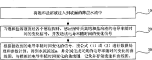
As shown in Figure 2, be the method flow diagram of the measuring flow rate of thin water flow by electrolyte tracing of inventive embodiments, this method is used the device of the foregoing description, and this method comprises the steps:
This step is used the electrolyte pulse generator, and saturated salt solution is injected in the electrolyte pulse generator, and the electrolyte pulse generator is injected into saturated salt solution in the sheet flow according to the control indication of data capture management device;
In this step, inducing probes is sent to the data capture management device with the signal that collects, and the data capture management device is sent to this signal operation control computer system again;
The time dependent signal of conductivity that step 30, basis receive, by formula (1) or (2) carries out data processing and calculation of parameter, try to achieve flow rate of water flow u, and the conductivity time history plot of generate gathering respectively, with the conductivity time history plot of simulation, record and storage flow velocity and curve map.
The intrasystem data analysis computing system of operation control computer utilizes formula (1) or (2) to calculate flow rate of thin water flow.
As shown in Figure 3, be device embodiment two structural representations of the measuring flow rate of thin water flow by electrolyte tracing of the embodiment of the invention; Present embodiment is simulated the measuring process to flow rate of thin water flow on domatic in testing laboratory, as the accuracy and the efficient of example checking this method, present embodiment also is provided with organic glass groove 5 and water yield injection device 6 for this reason.
Organic glass groove 5 long 4m wherein, high 50cm, wide 15cm is certain slope and places, and such as can being 4 ° with ground, or 8 °, or 12 ° of angles wait and place, and are used for that is virtually reality like reality domatic.In the more stable position of organic glass groove 5 top current the solution decanting point is set, rule of thumb, current reach stable generally speaking apart from the 1m place, top of organic glass groove 1, therefore can the solution decanting point be set at this point; Water yield injection device 6 is used for injecting clear water to organic glass groove 5, forms the runoff of certain flow, is used to simulate domatic sheet flow; Electrolyte pulse generator 1 is placed near the solution decanting point, is used for saturated potassium chloride (salt) solution is injected organic glass guide channel 5; Inducing probes 2 is arranged on the organic glass groove 5 with certain spacing, is used to gather the time dependent signal of conductivity of salt solusion, and the signal that collects is sent to data capture management device 3; Can be arranged on apart from solution decanting point 5cm, 30cm, 60cm, 90cm, 120cm and 150cm place such as inducing probes 2.Data capture management device 3 is connected with inducing probes 2, be used to receive the signal that inducing probes 2 is gathered, the signal that receives is sent to operation control computer system 4, operation control computer system 4 is according to the conductivity signal that receives, generate the conductivity time history plot of actual measurement, and the time dependent function relation figure of conductivity of simulation, and by formula (1) or (2) as calculated machine simulation try to achieve flow rate of water flow u.
As shown in Figure 4, be the boundary condition conductivity time history plot of the actual measurement of the embodiment of the invention two.
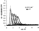
According to the time dependent data of concentration of salt solution data that record under the different tests condition, according to formula (1) computation model parameter, obtain matched curve figure that normal model under the different tests condition and actual measurement solute concentration change shown in Fig. 5 (a)-(i), as can be seen from the figure, the solution concentration and the measured data match of normal model prediction reach unanimity, can catch the trend of peak value and density loss preferably, determine that coefficient is substantially all greater than 0.9.The mean flow rate that the different measuring distance calculation obtains under the different tests condition is as shown in table 1.By data in the table 1 as can be seen, the mean flow rate of model prediction increases gradually along with the increase of the gradient and flow, and this is true to life.In addition, the mean flow velocity value difference of different measuring position prediction is very little, and this also is consistent with the prerequisite of Model Calculation.Therefore, the theory and the parametric solution rationality of procedure of normal model are described.
Table 1: the mean flow velocity value that normal model and sinusoidal model calculate (m/s)

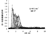
The time dependent data of concentration of salt solution data that record according to the diverse location place, according to formula (2) computation model parameter, obtain matched curve figure that sinusoidal model under the different tests condition and actual measurement solute concentration change shown in Fig. 6 (a)-(i), by Fig. 6 (a)-(i) as seen, under different gradient and flow condition, sinusoidal model is very consistent with the match of measured data.Along with the increase of the gradient and flow, the single electrolyte significantly shortened by the time of inducing probes.Determine that coefficient is almost all greater than 0.9.
Under the different tests condition, sinusoidal model is as shown in table 1 at the current mean flow velocity value of each place, measuring position prediction.Changing Pattern between the flow speed value that the test figure of utilizing the diverse location place to measure calculates is not clearly, and the result of T check also shows that flow velocity does not have significant difference between different measuring positions.This result shows that insulated stream is stable state basically, and this hypothesis with model is consistent.The slope flow flow velocity is along with the increase of flow and organic glass trough slope is the trend of increase, and flow is more remarkable to the influence of flow velocity than the gradient to the influence of flow velocity, and this conclusion is rational.Therefore, by the analysis showed that, it is rational utilizing the sine function simulation border to calculate the shallow flow on slopes flow velocity.
The rationality that predicts the outcome the prediction of comparative analysis flow velocity below by normal model and sinusoidal model.As shown in Figure 7, the flow speed value of measuring under the different tests condition for normal model and sinusoidal model is synoptic diagram relatively, and as seen, all data points nearly all drop near the straight line of 1:1, illustrate that two models do not have significant difference when predicted velocity.
Therefore, normal distyribution function and sine function all can be simulated the boundary condition of actual acquisition preferably, normal model of setting up as boundary condition and sinusoidal model be the measured data of match position well, and prediction flow rate of water flow value has rationality with the variation of the flow and the gradient.Average flow rate of water flow by two model predictions does not have significant difference, has further proved the rationality and the feasibility of model.
Below the discharge method of measurement flow rate in normal model, sinusoidal model and the prior art of the embodiment of the invention and the measurement result of floating thing method are compared the accuracy of checking normal model and sinusoidal model predicted velocity.As shown in Figure 8, be the comparison synoptic diagram of the result of calculation of the measurement result of existing measuring method and the inventive method, and utilize linear regression fit.The result shows: the flow speed value that discharge method records is normal model and sinusoidal model result of calculation 0.789 times, and deterministic coefficient is 0.854.The flow ratio juris is to utilize the monitoring water flow and the depth of water to calculate flow velocity, wherein flow is measured with integral bucket, depth of water water level instrumentation amount, the flow velocity precision that discharge method calculates depends primarily on the measuring accuracy of the depth of water, because the precision of water level gauge is 1/10mm, this just means that discharge method measurement flow rate of thin water flow also has 10% relative error.Analyze in view of the above, flow speed value that discharge method is measured and the difference between normal model and the sinusoidal model result of calculation can be explained, can reflect the rationality of The model calculation.The flow speed value that the floating thing method is measured is 1.013 times of method result of calculation of the present invention, and deterministic coefficient is 0.801, and the flow velocity difference that records with the present invention is very little, and this result further illustrates the accuracy of normal model and sinusoidal model result of calculation.
The device and method of measuring flow rate of thin water flow by electrolyte tracing provided by the invention, by with the conductivity of solution over time signal as the boundary condition of convection current disperse equation, by combining of numerical evaluation and modern surveying technology, realized the interior measurement of short distance to flow rate of thin water flow, improved measuring accuracy greatly, and simple to operate, instrument is portable, for Model of Soil Erosion and association area research provide a good survey instrument.
The above only is a preferred implementation of the present invention; should be pointed out that for those skilled in the art, under the prerequisite that does not break away from the technology of the present invention principle; can also make some improvement and modification, these improve and modification also should be considered as protection scope of the present invention.
Claims (4)
1. the device of a measuring flow rate of thin water flow by electrolyte tracing is characterized in that, described device is placed on and produces on sheet flow domatic, and described device comprises:
The electrolyte pulse generator is used for injecting salt solusion in described sheet flow;
Several inducing probes, with a determining deviation be arranged on described domatic on, be used to gather the time dependent signal of electrical conductivity of solution, the signal that collects is sent to the data capture management device;
Described data capture management device, be connected with inducing probes with described electrolyte pulse generator, be used to control described electrolyte pulse generator and begin in sheet flow, to inject solution, also be used for the signal that inducing probes sends is sent to operation control computer system;
Described operation control computer system is connected with described data capture management device, is used for according to the time dependent signal of conductivity that receives, and by formula (1) or (2) carries out data processing and calculation of parameter, obtains flow rate of water flow u;
Wherein C represents normalized electrical conductivity of solution; X represents that unit is m along the coordinate of described domatic length of grade direction; U represents flow rate of water flow, and unit is m/s; T express time, unit are s; D
HExpression hydrodynamic dispersion coefficient, unit is m
2/ s; A, B, D are undetermined parameter.
2. the device of measuring flow rate of thin water flow by electrolyte tracing as claimed in claim 1 is characterized in that, described operation control computer system control electrolyte pulse generator begins to inject solution in sheet flow.
3. the method for the measuring flow rate of thin water flow by electrolyte tracing of the device of a measuring flow rate of thin water flow by electrolyte tracing that uses claim 1 is characterized in that, comprises the steps:
Step 10, salt solusion is injected in the shallow flow on slopes;
Step 20, when the salt solusion flows through all inducing probes, inducing probes is gathered the time dependent signal of conductivity of salt solusion, and sends the time dependent signal of described conductivity to the data capture management device;
Step 30, data capture management device send to operation control computer system with the signal that receives, the data analysis unit of operation control computer system is according to the time dependent signal of conductivity that receives, by formula (1) or (2) carries out data processing and calculation of parameter, obtain flow rate of water flow u, and the conductivity time history plot of generate gathering respectively, conductivity time history plot with simulation writes down and stores described flow velocity and curve map;
4. the method for measuring flow rate of thin water flow by electrolyte tracing according to claim 3 is characterized in that, described formula (1) or (2) obtain in accordance with the following methods:
For convection current disperse equation (3):
When upper boundary conditions is impulse function (4):
C(x,t)=δ(t) x=0 (4)
Downstream condition is (5):
C(x,t)=0 x=∞ (5)
Starting condition is (6): the initial concentration of solute is zero:
C (x, t)=0 during t=0 (6), the analytic solution of (3) are:
Under the situation of known (7), the response of the input signal of linear system is the convolution of input signal and impulse response function, and expression formula is:
Will apart from described electrolyte pulse take place conductivity that inducing probes the most nearby gathers over time signal as the boundary condition of (3), described boundary condition is described with normal state or sine function, wherein the expression formula of normal function simulating boundary condition is (8), the expression formula of sine function simulation boundary condition is (10)
In (7) and (8) substitutions (9), find the solution and obtain formula (1),
In (7) and (10) substitutions (9), find the solution and obtain formula (2).
Priority Applications (1)
| Application Number | Priority Date | Filing Date | Title |
|---|---|---|---|
| CN2010101715215A CN101825646B (en) | 2010-05-07 | 2010-05-07 | Method for measuring flow rate of thin water flow by electrolyte tracing |
Applications Claiming Priority (1)
| Application Number | Priority Date | Filing Date | Title |
|---|---|---|---|
| CN2010101715215A CN101825646B (en) | 2010-05-07 | 2010-05-07 | Method for measuring flow rate of thin water flow by electrolyte tracing |
Publications (2)
| Publication Number | Publication Date |
|---|---|
| CN101825646A true CN101825646A (en) | 2010-09-08 |
| CN101825646B CN101825646B (en) | 2012-11-07 |
Family
ID=42689683
Family Applications (1)
| Application Number | Title | Priority Date | Filing Date |
|---|---|---|---|
| CN2010101715215A Expired - Fee Related CN101825646B (en) | 2010-05-07 | 2010-05-07 | Method for measuring flow rate of thin water flow by electrolyte tracing |
Country Status (1)
| Country | Link |
|---|---|
| CN (1) | CN101825646B (en) |
Cited By (8)
| Publication number | Priority date | Publication date | Assignee | Title |
|---|---|---|---|---|
| CN102680732A (en) * | 2012-05-24 | 2012-09-19 | 中国农业大学 | Method and system for measuring velocity of sheet flow on slope |
| CN105911306A (en) * | 2016-05-10 | 2016-08-31 | 河海大学 | Flow velocity automatic measuring device and measuring method |
| CN108152002A (en) * | 2017-12-13 | 2018-06-12 | 中山大学 | A kind of four-dimensional intelligent imager of multi-functional flow |
| CN108759949A (en) * | 2018-05-30 | 2018-11-06 | 河海大学 | Measure the device and its operating method of phytal zone groundwater discharge |
| CN110441547A (en) * | 2019-09-04 | 2019-11-12 | 中国电建集团中南勘测设计研究院有限公司 | A kind of flow rate of water flow measurement method |
| CN110441546A (en) * | 2019-09-04 | 2019-11-12 | 中国电建集团中南勘测设计研究院有限公司 | A kind of discharge structure flow rate of water flow measuring device and method |
| CN111366747A (en) * | 2020-03-30 | 2020-07-03 | 中国农业大学 | Method for improving electrolyte tracing and measuring erosion slope water flow velocity |
| CN113009177A (en) * | 2021-02-09 | 2021-06-22 | 中国农业大学 | Method for measuring flow velocity of slope surface by electrolyte centroid method |
Citations (1)
| Publication number | Priority date | Publication date | Assignee | Title |
|---|---|---|---|---|
| CN1354357A (en) * | 2001-12-18 | 2002-06-19 | 中国科学院水利部水土保持研究所 | Method for measuring flow velocity and sediment content of water flow by electrolyte pulse method |
-
2010
- 2010-05-07 CN CN2010101715215A patent/CN101825646B/en not_active Expired - Fee Related
Patent Citations (1)
| Publication number | Priority date | Publication date | Assignee | Title |
|---|---|---|---|---|
| CN1354357A (en) * | 2001-12-18 | 2002-06-19 | 中国科学院水利部水土保持研究所 | Method for measuring flow velocity and sediment content of water flow by electrolyte pulse method |
Non-Patent Citations (3)
| Title |
|---|
| 《中国农业大学学报》 20100430 史晓楠 雷廷武 张勇 降雨条件下电解质示踪正态模型的应用 125-126 1-4 , 第4期 2 * |
| 《水科学进展》 20031130 夏卫生等 薄层水流速度测量系统的研究 781-784 1-4 第14卷, 第6期 2 * |
| 《西北农林科技大学博士学位论文》 20030531 夏卫生 电解质脉冲法测量坡面薄层恒定水流速度的研究及其初步应用 14-25 1-4 , 2 * |
Cited By (12)
| Publication number | Priority date | Publication date | Assignee | Title |
|---|---|---|---|---|
| CN102680732A (en) * | 2012-05-24 | 2012-09-19 | 中国农业大学 | Method and system for measuring velocity of sheet flow on slope |
| CN105911306A (en) * | 2016-05-10 | 2016-08-31 | 河海大学 | Flow velocity automatic measuring device and measuring method |
| CN105911306B (en) * | 2016-05-10 | 2019-01-11 | 河海大学 | Flow velocity automatic measurement mechanism and measurement method |
| CN108152002A (en) * | 2017-12-13 | 2018-06-12 | 中山大学 | A kind of four-dimensional intelligent imager of multi-functional flow |
| CN108759949A (en) * | 2018-05-30 | 2018-11-06 | 河海大学 | Measure the device and its operating method of phytal zone groundwater discharge |
| CN110441547A (en) * | 2019-09-04 | 2019-11-12 | 中国电建集团中南勘测设计研究院有限公司 | A kind of flow rate of water flow measurement method |
| CN110441546A (en) * | 2019-09-04 | 2019-11-12 | 中国电建集团中南勘测设计研究院有限公司 | A kind of discharge structure flow rate of water flow measuring device and method |
| CN110441547B (en) * | 2019-09-04 | 2021-11-05 | 中国电建集团中南勘测设计研究院有限公司 | Water flow velocity measuring method |
| CN111366747A (en) * | 2020-03-30 | 2020-07-03 | 中国农业大学 | Method for improving electrolyte tracing and measuring erosion slope water flow velocity |
| CN111366747B (en) * | 2020-03-30 | 2021-02-05 | 中国农业大学 | Method for improving electrolyte tracing and measuring erosion slope water flow velocity |
| CN113009177A (en) * | 2021-02-09 | 2021-06-22 | 中国农业大学 | Method for measuring flow velocity of slope surface by electrolyte centroid method |
| CN113009177B (en) * | 2021-02-09 | 2022-07-05 | 中国农业大学 | Method for measuring flow velocity of slope surface by electrolyte centroid method |
Also Published As
| Publication number | Publication date |
|---|---|
| CN101825646B (en) | 2012-11-07 |
Similar Documents
| Publication | Publication Date | Title |
|---|---|---|
| CN101825646B (en) | Method for measuring flow rate of thin water flow by electrolyte tracing | |
| Lane et al. | Modelling erosion on hillslopes | |
| CN108254032A (en) | River ultrasonic wave time difference method method of calculating flux | |
| CN102680732A (en) | Method and system for measuring velocity of sheet flow on slope | |
| CN206056580U (en) | A kind of hydrometric cableway surveys husky device automatically | |
| WO2009117784A1 (en) | System, apparatus and method for measuring soil moisture content | |
| CN105486487A (en) | Wave detection system | |
| CN107092759A (en) | Dam body displacement monitoring point optimization method for arranging based on Gravity Dam Foundation parametric inversion | |
| CN104793249A (en) | Method for systematically detecting seawater intrusion | |
| CN107167576A (en) | Unsaturated soil disorderly scattered kinetic coefficient assay method and device | |
| Shi et al. | Measuring shallow water flow velocity with virtual boundary condition signal in the electrolyte tracer method | |
| CN102419248A (en) | Device and method for measuring soil wind erosion rate | |
| CN113484210B (en) | On-site scale test determination method for dispersity of strongly weathered layer | |
| CN108398236A (en) | Inclined tube-type settling pit information of flow and Sediment Transport characteristic measurement method and system | |
| CN103196515A (en) | Wave and tide level testing device | |
| Chauhan et al. | Comparison of discharge data using ADCP and current meter | |
| Griffith et al. | The North Wyke Farm Platform: methodologies used in the remote sensing of the quantity and quality of drainage water | |
| Comina et al. | Geophysical methods to support correct water sampling locations for salt dilution gauging | |
| CN116956772A (en) | Unified prediction method and device for sediment scouring rate of vegetation-free areas and vegetation areas | |
| CN108692773B (en) | Tentacle type sensing flow meter based on artificial intelligence technology and flow measuring method thereof | |
| CN105806434A (en) | System for measuring flow of open channel | |
| CN203259442U (en) | Salt spray precipitation rate multi-measure-point real-time automatic detection apparatus | |
| CN116165718A (en) | Method and device for measuring seepage safety of earth and rockfill dam, electronic equipment and medium | |
| CN103411850B (en) | The flowing reduction experiment method of rubble flow unit weight | |
| CN1219207C (en) | Method for measuring flow velocity and sediment content of water flow by electrolyte pulse method |
Legal Events
| Date | Code | Title | Description |
|---|---|---|---|
| C06 | Publication | ||
| PB01 | Publication | ||
| C10 | Entry into substantive examination | ||
| SE01 | Entry into force of request for substantive examination | ||
| C14 | Grant of patent or utility model | ||
| GR01 | Patent grant | ||
| CF01 | Termination of patent right due to non-payment of annual fee |
Granted publication date: 20121107 Termination date: 20190507 |
|
| CF01 | Termination of patent right due to non-payment of annual fee |