CN102680732A - Method and system for measuring velocity of sheet flow on slope - Google Patents
Method and system for measuring velocity of sheet flow on slope Download PDFInfo
- Publication number
- CN102680732A CN102680732A CN2012101654649A CN201210165464A CN102680732A CN 102680732 A CN102680732 A CN 102680732A CN 2012101654649 A CN2012101654649 A CN 2012101654649A CN 201210165464 A CN201210165464 A CN 201210165464A CN 102680732 A CN102680732 A CN 102680732A
- Authority
- CN
- China
- Prior art keywords
- tau
- flow
- convection current
- slopes
- boundary condition
- Prior art date
- Legal status (The legal status is an assumption and is not a legal conclusion. Google has not performed a legal analysis and makes no representation as to the accuracy of the status listed.)
- Granted
Links
Images


Landscapes
- Measuring Volume Flow (AREA)
Abstract
The invention relates to the technical field of boundary obtaining, and discloses a method and system for measuring velocity of sheet flow on a slope. Through the boundary conditions expressed by sine functions and normal distribution functions, the method and the system realize measurement on the velocity of sheet flow on the slope and solve the problem that the flow velocity measurement precision is low due to inaccurate boundary condition measurement, and therefore the precision of measurement on the velocity of sheet flow on the slope is increased. In addition, the fact that the boundary conditions are calculated first and then the velocity of sheet flow on the slope is calculated is not needed, while the velocity of sheet flow and the boundary conditions are calculated at the same time, and further the efficiency of velocity of sheet flow measurement is increased.
Description
Technical field
The present invention relates to the border and obtain technical field, particularly a kind of shallow flow on slopes flow-speed measurement method and system.
Background technology
The method of electrolyte pulse model measurement shallow flow on slopes flow velocity can accurately be predicted flow rate of water flow under certain condition theoretically.Yet because the restriction of equipment, the input border is that the supposition of impulse function is difficult to realize in practice, and is especially bigger for short distance flow-speed measurement error.People such as summer health show that through experiment results the pulse model method reaches 38% in the flow velocity relative error of measuring apart from electrolyte decanting point 0.5m place.Electrolyte tracing actual measurement boundary condition method is apart from the newly-increased one group of probe in the about 0.05m of electrolyte decanting point place, measures the boundary condition of electrolyte concentration signal as model, has improved the hypothesis on pulse border in the original model.This method is utilized normal distyribution function and sine function form simulation solute input border respectively; The development of theory has been played the effect of promotion; Than the pulse model, this method has significantly improved the flow velocity accuracy of predicting, yet; The approximation to function ground that model employing 0.05m place measures still is not the real border condition that occurs in the 0m place as boundary condition.Reaction on time and distance is highstrung because this method is to boundary condition, the inaccurate error that will cause fluid-velocity survey of boundary condition.
Summary of the invention
The technical matters that (one) will solve
The technical matters that the present invention will solve is: the precision that how to improve the shallow flow on slopes fluid-velocity survey.
(2) technical scheme
For solving the problems of the technologies described above, the invention provides a kind of shallow flow on slopes flow-speed measurement method, said method comprises:
Cross section to be measured in current shallow flow on slopes is provided with inducing probes, injects electrolyte in the precalculated position at the said inducing probes upper reaches, and the distance of establishing between said precalculated position and the cross section to be measured is x;
Said inducing probes is gathered the conductivity in said cross section to be measured, and said conductivity is scaled the normalization electrolyte concentration;
Utilize said normalization electrolyte concentration, apart from x, and the boundary condition that adopts sine function and normal distyribution function to represent calculate the flow velocity of said current shallow flow on slopes.
Preferably, the flow velocity that calculates said current shallow flow on slopes specifically may further comprise the steps:
With said normalization electrolyte concentration and apart from x respectively substitution adopt convection current disperse equation w that sine function representes boundary condition and adopt normal distyribution function to represent among the convection current disperse equation m of boundary condition; Said convection current disperse equation w and convection current disperse equation m are carried out match, to obtain the flow velocity of said current shallow flow on slopes.
Preferably, said convection current disperse equation is:
Wherein,
D
HBe the hydrodynamic dispersion coefficient, t is the time, and u is the flow velocity of said current shallow flow on slopes, and f (τ) is said boundary condition, C
1(x t) is said normalization electrolyte concentration.
Preferably, said convection current disperse equation w is:
Said convection current disperse equation m is:
Wherein, A, B and D are the coefficient to be determined of said boundary condition.
Preferably, adopt least square method to carry out match to said convection current disperse equation w and convection current disperse equation m.
The invention also discloses a kind of shallow flow on slopes flow velocity measuring system, said system comprises:
Probe is provided with module, is used in the cross section to be measured of current shallow flow on slopes inducing probes being set, and injects electrolyte in the precalculated position at the said inducing probes upper reaches, and the distance of establishing between said precalculated position and the cross section to be measured is x;
The conversion module is used for the conductivity that said inducing probes is gathered said cross section to be measured, and said conductivity is scaled the normalization electrolyte concentration;
The flow velocity computing module, be used to utilize said normalization electrolyte concentration, apart from x, and the boundary condition that adopts sine function and normal distyribution function to represent calculate the flow velocity of said current shallow flow on slopes.
Preferably, the flow velocity that calculates said current shallow flow on slopes specifically may further comprise the steps:
With said normalization electrolyte concentration and apart from x respectively substitution adopt convection current disperse equation w that sine function representes boundary condition and adopt normal distyribution function to represent among the convection current disperse equation m of boundary condition; Said convection current disperse equation w and convection current disperse equation m are carried out match, to obtain the flow velocity of said current shallow flow on slopes.
Preferably, said convection current disperse equation is:
Wherein,
D
HBe the hydrodynamic dispersion coefficient, t is the time, and u is the flow velocity of said current shallow flow on slopes, and f (τ) is said boundary condition, C
1(x t) is said normalization electrolyte concentration.
Preferably, said convection current disperse equation w is:
Said convection current disperse equation m is:
Wherein, A, B and D are the coefficient to be determined of said boundary condition.
Preferably, adopt least square method to carry out match to said convection current disperse equation w and convection current disperse equation m.
(3) beneficial effect
The present invention realizes the shallow flow on slopes fluid-velocity survey with the boundary condition that sine function and normal distyribution function are expressed; Evaded because of boundary condition and measured the inaccurate low problem of fluid-velocity survey precision that causes, thereby improved the precision of shallow flow on slopes fluid-velocity survey.In addition, do not need first calculation of boundary conditions, calculate the shallow flow on slopes flow velocity again, but calculate flow rate of water flow and boundary condition simultaneously, and then improved the efficient of fluid-velocity survey.
Description of drawings
Fig. 1 is the process flow diagram according to the shallow flow on slopes flow-speed measurement method of one embodiment of the present invention;
Fig. 2 is the structured flowchart according to the shallow flow on slopes flow velocity measuring system of one embodiment of the present invention;
Fig. 3 is the experiment hardware structure diagram according to an embodiment of the present invention;
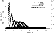
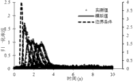
Fig. 4 is to be 12L min at flow
-1And the gradient is under 4 ° the condition, the normalization concentration synoptic diagram of the measured value and the analogue value;
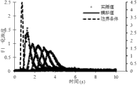
Fig. 5 is to be 12L min at flow
-1And the gradient is under 8 ° the condition, the normalization concentration synoptic diagram of the measured value and the analogue value;
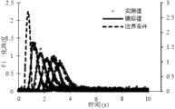
Fig. 6 is to be 12L min at flow
-1And the gradient is under 12 ° the condition, the normalization concentration synoptic diagram of the measured value and the analogue value;
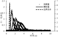
Fig. 7 is to be 24L min at flow
-1And the gradient is under 4 ° the condition, the normalization concentration synoptic diagram of the measured value and the analogue value;
Fig. 8 is to be 24L min at flow
-1And the gradient is under 8 ° the condition, the normalization concentration synoptic diagram of the measured value and the analogue value;
Fig. 9 is to be 24L min at flow
-1And the gradient is under 12 ° the condition, the normalization concentration synoptic diagram of the measured value and the analogue value;
Figure 10 is to be 48L min at flow
-1And the gradient is under 4 ° the condition, the normalization concentration synoptic diagram of the measured value and the analogue value;
Figure 11 is to be 48L min at flow
-1And the gradient is under 8 ° the condition, the normalization concentration synoptic diagram of the measured value and the analogue value;
Figure 12 is to be 48L min at flow
-1And the gradient is under 12 ° the condition, the normalization concentration synoptic diagram of the measured value and the analogue value;
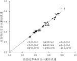
Figure 13 is boundary condition corresponding flow rate result comparison diagram when passing through normal distyribution function and sine function and representing;
Figure 14 is boundary condition corresponding determinacy coefficient (R when passing through normal distyribution function and sine function and representing
2) comparison diagram as a result;
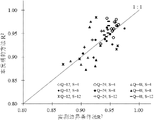
The comparison diagram of Figure 15 flow speed value that to be method of the present invention calculate respectively with actual measurement boundary condition method;
The comparison diagram of Figure 16 determinacy coefficient that to be method of the present invention calculate respectively with actual measurement boundary condition method;
The average statistical comparison diagram of Figure 17 determinacy coefficient that to be method of the present invention calculate respectively with actual measurement boundary condition method.
Embodiment
Below in conjunction with accompanying drawing and embodiment, specific embodiments of the invention describes in further detail.Following examples are used to explain the present invention, but are not used for limiting scope of the present invention.
Fig. 1 is the process flow diagram according to the shallow flow on slopes flow-speed measurement method of one embodiment of the present invention; With reference to Fig. 1, said method comprises:
Cross section to be measured in current shallow flow on slopes is provided with inducing probes, injects electrolyte in the precalculated position at the said inducing probes upper reaches, and the distance of establishing between said precalculated position and the cross section to be measured is x;
Said inducing probes is gathered the conductivity in said cross section to be measured, and said conductivity is scaled the normalization electrolyte concentration;
Utilize said normalization electrolyte concentration, apart from x, and the boundary condition that adopts sine function and normal distyribution function to represent calculate the flow velocity of said current shallow flow on slopes.
Preferably, the flow velocity that calculates said current shallow flow on slopes specifically may further comprise the steps:
With said normalization electrolyte concentration and apart from x respectively the substitution boundary condition adopt among the convection current disperse equation m that convection current disperse equation w that sine function representes and boundary condition employing normal distyribution function represent; Said convection current disperse equation w and convection current disperse equation m are carried out match (in this embodiment; Adopt least square method to carry out match to said convection current disperse equation w and convection current disperse equation m), to obtain the flow velocity of said current shallow flow on slopes.
Describing the convection current disperse equation expression formula of solute in the one-dimensional stable current is:
In the formula, h is a flow depth; W is a flow width; C is normalized solution concentration; X is the distance between said precalculated position and the cross section to be measured, and its unit is m; U is a flow rate of water flow, and its unit is m/s; T is the time, and its unit is s; D
HBe the hydrodynamic dispersion coefficient, its unit is m
2/ s.
Do not consider rainfall and infiltrate under the influence condition that flow is a constant, the variation of flow rate of water flow can be ignored, therefore:
Put in order:
hw=constant (3)
Wherein, Q
0It is flow.
In conjunction with formula (1) and formula (3), obtain:
Boundary condition is assumed to be impulse function, and starting condition and boundary condition are provided by following formula:
C(x,t)/C
0=δ(t=t
0) x=0(4a)
C(x,t)=0 x=∞ (4b)
C(x,t)=0 t=0 (4c)
δ in the formula (t) is the unit impulse function at electrolyte decanting point place; C
0By
 Normalization concentration after the rectification.
Therefore, can calculate the top analytic solution of boundary value problem just is:
Electrolyte generally adopts salt solusion in actual tests operation, because the restriction of salt solusion injection device, the time of injecting solution is not reach impulse function effect on the theory significance.If real boundary condition functional form is with f (t) expression, corresponding output signal can be calculated with the convolution of true input signal and impulse response, and preferably, said convection current disperse equation is:
Wherein,
D
HBe the hydrodynamic dispersion coefficient, t is the time, and u is the flow velocity of said current shallow flow on slopes, and f (τ) is said boundary condition, C
1(x t) is said normalization electrolyte concentration.
Boundary condition still adopts sine function and two kinds of forms of normal distyribution function to express, and is respectively:
In the formula, A, B, D are definite coefficient of boundary condition.
Preferably, said convection current disperse equation w is:
Said convection current disperse equation m is:
Wherein, A, B and D are the coefficient to be determined of said boundary condition.
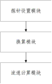
Fig. 2 is the structured flowchart according to the shallow flow on slopes flow velocity measuring system of one embodiment of the present invention; With reference to Fig. 2, said system comprises:
Probe is provided with module, is used in the cross section to be measured of current shallow flow on slopes inducing probes being set, and injects electrolyte in the precalculated position at the said inducing probes upper reaches, and the distance of establishing between said precalculated position and the cross section to be measured is x;
The conversion module is used for the conductivity that said inducing probes is gathered said cross section to be measured, and said conductivity is scaled the normalization electrolyte concentration;
The flow velocity computing module, be used to utilize said normalization electrolyte concentration, apart from x, and the boundary condition that adopts sine function and normal distyribution function to represent calculate the flow velocity of said current shallow flow on slopes.
Preferably, the flow velocity that calculates said current shallow flow on slopes specifically may further comprise the steps:
With said normalization electrolyte concentration and apart from x respectively substitution adopt convection current disperse equation w that sine function representes boundary condition and adopt normal distyribution function to represent among the convection current disperse equation m of boundary condition; Said convection current disperse equation w and convection current disperse equation m are carried out match, to obtain the flow velocity of said current shallow flow on slopes.
Preferably, said convection current disperse equation is:
Wherein,
D
HBe the hydrodynamic dispersion coefficient, t is the time, and u is the flow velocity of said current shallow flow on slopes, and f (τ) is said boundary condition, C
1(x t) is said normalization electrolyte concentration.
Preferably, said convection current disperse equation w is:
Said convection current disperse equation m is:
Wherein, A, B and D are the coefficient to be determined of said boundary condition.
Preferably, adopt least square method to carry out match to said convection current disperse equation w and convection current disperse equation m.
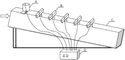
With reference to Fig. 3; Experiment hardware configuration in the present embodiment is made up of 5 parts; Be respectively tank C, electrolyte pulse generator A, water yield injection unit (not shown, the direction of arrow is in the drawings injected water by certain flow), conductivity probe B (being inducing probes) and data acquisition and memory device D.Test water flute length 4m, wide 15cm, high 50cm.When current reach stable after; Inject the KCl solution (salt solusion) of high concentration by electrolyte pulse generator (being positioned at said precalculated position) from the top of tank; The conductivity of inducing probes (being positioned at said cross section to be measured) monitoring is exported by computing machine through data acquisition system (DAS), and data acquiring frequency is 100 points of per second.
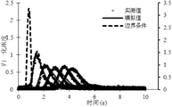
Fig. 4 ~ 12nd is in different flow and different gradient; The normalization solubility synoptic diagram of the measured value and the analogue value; Wherein, The ordinate of the leftmost side is measured value and the corresponding normalization concentration of the analogue value among the figure, and the ordinate of the rightmost side is the corresponding normalization concentration of boundary condition among the figure, and the flow rate of water flow and the deterministic coefficient of calculating are listed in the table 1.
Visible by Fig. 4 ~ 12, the match preferably of different experimental conditions drag the electrolyte concentration variation tendency that records of diverse location, along with the increase of measuring distance, peak of curve reduces gradually.Along with the increase of the flow and the gradient, time of break-through reduces gradually.

Table 1
The flow speed value that records at different distance x changes not remarkable, and along with the increase of flow and the gradient, flow velocity is increase trend, and this conclusion is rational, and the validity of the inventive method also has been described.The determinacy coefficient of all measuring position place's model fittings shows the measured result under the model match different experiments preferably working condition all greater than 0.9.
For the ease of parameter comparison, Figure 13 and Figure 14 put respectively to have painted and utilize normal function and the sine function comparing result as the model parameter of boundary condition respectively.
Among Figure 13 and Figure 14, the data point of flow rate of water flow and deterministic coefficient explains that all closely around the straight line of 1:1 the flow rate result that two kinds of boundary condition forms are calculated is consistent.Utilize the T check to analyze respectively to two groups of data, show and utilize normal function and two kinds of functional forms of sine function all not to have significant difference as flow velocity and the deterministic coefficient that virtual boundary calculates.This result shows that sine function and normal function all can describe real boundary condition exactly, and has further proved the rationality of the inventive method.
Utilize method of the present invention and actual measurement boundary condition method that measured data is carried out match respectively, and calculate flow rate of water flow and deterministic coefficient.Figure 15 and Figure 16 comparative analysis two kinds of flow speed value and computational accuracies that method is calculated under different experimental conditions and measuring position situation.
Visible by Figure 15 and Figure 16, the flow speed value that the following two kinds of methods of different experimental conditions are measured is the consistance Changing Pattern.Most of hollow dots (4 °) is positioned at below the 1:1 line, and solid dot (8 °) is distributed on the 1:1 straight line, and cross label (12 °) is positioned at 1:1 line top.Be illustrated in the tank gradient hour; The flow speed value that method of the present invention is calculated is lower than the flow speed value that actual measurement boundary condition method is calculated; When the gradient arrives 8 °; The flow speed value of two kinds of method measurements is suitable, and when the gradient continued to increase, the flow speed value that method of the present invention is calculated will be higher than the flow speed value of actual measurement boundary condition method calculating.The determinacy coefficient of match is distributed near the 1:1 straight line, and average statistical analysis result (Figure 17) shows that fluid-velocity survey precision of the present invention will be higher than the actual measurement boundary condition.
Above embodiment only is used to explain the present invention; And be not limitation of the present invention; The those of ordinary skill in relevant technologies field under the situation that does not break away from the spirit and scope of the present invention, can also be made various variations and modification; Therefore all technical schemes that are equal to also belong to category of the present invention, and scope of patent protection of the present invention should be defined by the claims.
Claims (10)
1. a shallow flow on slopes flow-speed measurement method is characterized in that, said method comprises:
Cross section to be measured in current shallow flow on slopes is provided with inducing probes, injects electrolyte in the precalculated position at the said inducing probes upper reaches, and the distance of establishing between said precalculated position and the cross section to be measured is x;
Said inducing probes is gathered the conductivity in said cross section to be measured, and said conductivity is scaled the normalization electrolyte concentration;
Utilize said normalization electrolyte concentration, apart from x, and the boundary condition that adopts sine function and normal distyribution function to represent calculate the flow velocity of said current shallow flow on slopes.
2. the method for claim 1 is characterized in that, the flow velocity that calculates said current shallow flow on slopes specifically may further comprise the steps:
With said normalization electrolyte concentration and apart from x respectively substitution adopt convection current disperse equation w that sine function representes boundary condition and adopt normal distyribution function to represent among the convection current disperse equation m of boundary condition; Said convection current disperse equation w and convection current disperse equation m are carried out match, to obtain the flow velocity of said current shallow flow on slopes.
3. method as claimed in claim 2 is characterized in that, said convection current disperse equation is:
Wherein,
D
HBe the hydrodynamic dispersion coefficient, t is the time, and u is the flow velocity of said current shallow flow on slopes, and f (τ) is said boundary condition, C
1(x t) is said normalization electrolyte concentration.
4. method as claimed in claim 3 is characterized in that, said convection current disperse equation w is:
Said convection current disperse equation m is:
Wherein, A, B and D are the coefficient to be determined of said boundary condition.
5. method as claimed in claim 2 is characterized in that, adopts least square method to carry out match to said convection current disperse equation w and convection current disperse equation m.
6. a shallow flow on slopes flow velocity measuring system is characterized in that, said system comprises:
Probe is provided with module, is used in the cross section to be measured of current shallow flow on slopes inducing probes being set, and injects electrolyte in the precalculated position at the said inducing probes upper reaches, and the distance of establishing between said precalculated position and the cross section to be measured is x;
The conversion module is used for the conductivity that said inducing probes is gathered said cross section to be measured, and said conductivity is scaled the normalization electrolyte concentration;
The flow velocity computing module, be used to utilize said normalization electrolyte concentration, apart from x, and the boundary condition that adopts sine function and normal distyribution function to represent calculate the flow velocity of said current shallow flow on slopes.
7. system as claimed in claim 6 is characterized in that, the flow velocity that calculates said current shallow flow on slopes specifically may further comprise the steps:
With said normalization electrolyte concentration and apart from x respectively substitution adopt convection current disperse equation w that sine function representes boundary condition and adopt normal distyribution function to represent among the convection current disperse equation m of boundary condition; Said convection current disperse equation w and convection current disperse equation m are carried out match, to obtain the flow velocity of said current shallow flow on slopes.
8. system as claimed in claim 7 is characterized in that, said convection current disperse equation is:
Wherein,
D
HBe the hydrodynamic dispersion coefficient, t is the time, and u is the flow velocity of said current shallow flow on slopes, and f (τ) is said boundary condition, C
1(x t) is said normalization electrolyte concentration.
9. system as claimed in claim 8 is characterized in that, said convection current disperse equation w is:
Said convection current disperse equation m is:
Wherein, A, B and D are the coefficient to be determined of said boundary condition.
10. system as claimed in claim 6 is characterized in that, adopts least square method to carry out match to said convection current disperse equation w and convection current disperse equation m.
Priority Applications (1)
| Application Number | Priority Date | Filing Date | Title |
|---|---|---|---|
| CN201210165464.9A CN102680732B (en) | 2012-05-24 | 2012-05-24 | Method and system for measuring velocity of sheet flow on slope |
Applications Claiming Priority (1)
| Application Number | Priority Date | Filing Date | Title |
|---|---|---|---|
| CN201210165464.9A CN102680732B (en) | 2012-05-24 | 2012-05-24 | Method and system for measuring velocity of sheet flow on slope |
Publications (2)
| Publication Number | Publication Date |
|---|---|
| CN102680732A true CN102680732A (en) | 2012-09-19 |
| CN102680732B CN102680732B (en) | 2014-04-16 |
Family
ID=46812973
Family Applications (1)
| Application Number | Title | Priority Date | Filing Date |
|---|---|---|---|
| CN201210165464.9A Expired - Fee Related CN102680732B (en) | 2012-05-24 | 2012-05-24 | Method and system for measuring velocity of sheet flow on slope |
Country Status (1)
| Country | Link |
|---|---|
| CN (1) | CN102680732B (en) |
Cited By (10)
| Publication number | Priority date | Publication date | Assignee | Title |
|---|---|---|---|---|
| CN105911306A (en) * | 2016-05-10 | 2016-08-31 | 河海大学 | Flow velocity automatic measuring device and measuring method |
| CN107290129A (en) * | 2017-05-04 | 2017-10-24 | 中国水利水电科学研究院 | A kind of domatic hydraulics model test flow field observation system and method |
| CN104535794B (en) * | 2015-01-16 | 2018-03-20 | 中国水利水电科学研究院 | A kind of flow rate of thin water flow measuring system and method |
| CN108759949A (en) * | 2018-05-30 | 2018-11-06 | 河海大学 | Measure the device and its operating method of phytal zone groundwater discharge |
| CN110441546A (en) * | 2019-09-04 | 2019-11-12 | 中国电建集团中南勘测设计研究院有限公司 | A kind of discharge structure flow rate of water flow measuring device and method |
| CN110823194A (en) * | 2019-11-18 | 2020-02-21 | 中国农业大学 | Method and device for measuring water depth of slope surface flow |
| CN111366747A (en) * | 2020-03-30 | 2020-07-03 | 中国农业大学 | Method for improving electrolyte tracing and measuring erosion slope water flow velocity |
| CN112462088A (en) * | 2020-11-18 | 2021-03-09 | 中国农业大学 | Method for measuring flow velocity of slope surface water flow through salt-heat coupling |
| CN112633554A (en) * | 2020-11-27 | 2021-04-09 | 北京林业大学 | Method and device for predicting slope laminar flow velocity correction coefficient |
| CN113009177A (en) * | 2021-02-09 | 2021-06-22 | 中国农业大学 | Method for measuring flow velocity of slope surface by electrolyte centroid method |
Citations (3)
| Publication number | Priority date | Publication date | Assignee | Title |
|---|---|---|---|---|
| US5040422A (en) * | 1989-03-04 | 1991-08-20 | Horst Frankenberger | Procedure for flow measurement and equipment therefor |
| CN1354357A (en) * | 2001-12-18 | 2002-06-19 | 中国科学院水利部水土保持研究所 | Method for measuring flow velocity and sediment content of water flow by electrolyte pulse method |
| CN101825646A (en) * | 2010-05-07 | 2010-09-08 | 中国农业大学 | Device and method for measuring flow rate of thin water flow by electrolyte tracing |
-
2012
- 2012-05-24 CN CN201210165464.9A patent/CN102680732B/en not_active Expired - Fee Related
Patent Citations (3)
| Publication number | Priority date | Publication date | Assignee | Title |
|---|---|---|---|---|
| US5040422A (en) * | 1989-03-04 | 1991-08-20 | Horst Frankenberger | Procedure for flow measurement and equipment therefor |
| CN1354357A (en) * | 2001-12-18 | 2002-06-19 | 中国科学院水利部水土保持研究所 | Method for measuring flow velocity and sediment content of water flow by electrolyte pulse method |
| CN101825646A (en) * | 2010-05-07 | 2010-09-08 | 中国农业大学 | Device and method for measuring flow rate of thin water flow by electrolyte tracing |
Non-Patent Citations (2)
| Title |
|---|
| TINGWU LEI ET AL.: "An improved method for shallow water flow velocity measurement with practical electrolyte inputs", 《JOURNAL OF HYDROLOGY》, no. 390, 31 December 2010 (2010-12-31), pages 45 - 46 * |
| 啜瑞媛等: "测量坡面薄层水流流速的电解质示踪真实边界条件法与系统", 《农业工程学报》, vol. 28, no. 2, 31 January 2012 (2012-01-31), pages 77 - 83 * |
Cited By (14)
| Publication number | Priority date | Publication date | Assignee | Title |
|---|---|---|---|---|
| CN104535794B (en) * | 2015-01-16 | 2018-03-20 | 中国水利水电科学研究院 | A kind of flow rate of thin water flow measuring system and method |
| CN105911306A (en) * | 2016-05-10 | 2016-08-31 | 河海大学 | Flow velocity automatic measuring device and measuring method |
| CN105911306B (en) * | 2016-05-10 | 2019-01-11 | 河海大学 | Flow velocity automatic measurement mechanism and measurement method |
| CN107290129A (en) * | 2017-05-04 | 2017-10-24 | 中国水利水电科学研究院 | A kind of domatic hydraulics model test flow field observation system and method |
| CN107290129B (en) * | 2017-05-04 | 2019-09-27 | 中国水利水电科学研究院 | A kind of slope surface hydraulics model test flow field observation system and method |
| CN108759949A (en) * | 2018-05-30 | 2018-11-06 | 河海大学 | Measure the device and its operating method of phytal zone groundwater discharge |
| CN110441546A (en) * | 2019-09-04 | 2019-11-12 | 中国电建集团中南勘测设计研究院有限公司 | A kind of discharge structure flow rate of water flow measuring device and method |
| CN110823194A (en) * | 2019-11-18 | 2020-02-21 | 中国农业大学 | Method and device for measuring water depth of slope surface flow |
| CN111366747A (en) * | 2020-03-30 | 2020-07-03 | 中国农业大学 | Method for improving electrolyte tracing and measuring erosion slope water flow velocity |
| CN111366747B (en) * | 2020-03-30 | 2021-02-05 | 中国农业大学 | Method for improving electrolyte tracing and measuring erosion slope water flow velocity |
| CN112462088A (en) * | 2020-11-18 | 2021-03-09 | 中国农业大学 | Method for measuring flow velocity of slope surface water flow through salt-heat coupling |
| CN112633554A (en) * | 2020-11-27 | 2021-04-09 | 北京林业大学 | Method and device for predicting slope laminar flow velocity correction coefficient |
| CN112633554B (en) * | 2020-11-27 | 2023-07-25 | 北京林业大学 | Slope thin-layer water flow velocity correction coefficient prediction method and device |
| CN113009177A (en) * | 2021-02-09 | 2021-06-22 | 中国农业大学 | Method for measuring flow velocity of slope surface by electrolyte centroid method |
Also Published As
| Publication number | Publication date |
|---|---|
| CN102680732B (en) | 2014-04-16 |
Similar Documents
| Publication | Publication Date | Title |
|---|---|---|
| CN102680732B (en) | Method and system for measuring velocity of sheet flow on slope | |
| CN101825646B (en) | Method for measuring flow rate of thin water flow by electrolyte tracing | |
| CN203037546U (en) | Imbibition experiment device | |
| CN203658217U (en) | Seepage starting pressure gradient test device | |
| CN100588915C (en) | Canal capacity analyzer and measuring method thereof | |
| CN104569480A (en) | Liquid impact force and flow velocity measuring instrument and measuring method thereof | |
| CN103185808A (en) | Photoelectric technology-based bubble velocity-measuring system | |
| CN105092684A (en) | Gas-liquid two-phase flow microbubble volume concentration measurement device | |
| CN102419248A (en) | Device and method for measuring soil wind erosion rate | |
| CN105547957A (en) | Method for calculating suction of infiltration wetting front of soil and spurt volume of rainfall | |
| CN206479214U (en) | Ultrasonic open-channel meter | |
| CN111089627A (en) | Multi-resolution open channel automatic flow measuring device based on area flow velocity method | |
| CN104036120A (en) | Single-point method for measuring fatigue S-N curve performance of materials and components | |
| CN103245765B (en) | A kind of Oceanic parameter measurement system | |
| CN201555609U (en) | Flow rate measuring device of silt wide river channel | |
| Sakphrom et al. | Simplified stream discharge estimation for hydrological application based on NB-IoT deployment | |
| CN105242063A (en) | Reservoir flow velocity measurement method based on pressure sensor | |
| CN104897088B (en) | A kind of ultrasonic wave measuring method of large scale structure relative displacement variable quantity | |
| CN203881383U (en) | Electrode type open channel flow meter | |
| CN203396514U (en) | Tide water body temperature field detection device | |
| CN203259328U (en) | Periodic non-contact turbulence structure measurement and control system for open-channel non-constant flow | |
| CN210464571U (en) | Channel flow measuring equipment | |
| CN204666303U (en) | A kind of Novel high-temperature high-pressure rises bubble instrument | |
| CN109975578A (en) | Runoff velocity method for real-time measurement, system and control device | |
| CN108038494B (en) | Two phase flow pattern recognition methods based on data fusion |
Legal Events
| Date | Code | Title | Description |
|---|---|---|---|
| C06 | Publication | ||
| PB01 | Publication | ||
| C10 | Entry into substantive examination | ||
| SE01 | Entry into force of request for substantive examination | ||
| C14 | Grant of patent or utility model | ||
| GR01 | Patent grant | ||
| CF01 | Termination of patent right due to non-payment of annual fee | ||
| CF01 | Termination of patent right due to non-payment of annual fee |
Granted publication date: 20140416 Termination date: 20210524 |