Embodiment
From hereinafter, will be with reference to accompanying drawing one explanation embodiments of the invention.Should understand following examples is suitably concrete examples of the present invention, has used various technical suitable restrictions on it, only if in following specification, indicate, scope of the present invention is not limited to these embodiment.This specification will be by following order setting.
1. first embodiment (first example of nonaqueous electrolyte battery)
2. second embodiment (battery pack example)
3. the 3rd embodiment (second example of nonaqueous electrolyte battery)
4. the 4th embodiment (the 3rd example of nonaqueous electrolyte battery)
5. the 5th embodiment (the 4th example of nonaqueous electrolyte battery)
6. other embodiment (modification)
1. first embodiment
< structure of nonaqueous electrolyte battery >
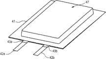
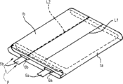
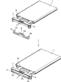
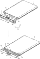
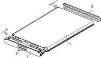
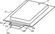
Fig. 1 to 3 illustrates the structure according to the nonaqueous electrolyte battery of first embodiment of the invention.As illustrated in fig. 1 and 2; Nonaqueous electrolyte battery has cell device 4; Said cell device 4 is contained in the recess 47 that forms in the stacked film 41, and three limits on decompression (reduced pressure) welding down-bonding cell device 4 peripheries except the bending side.As shown in Figure 3; Nonaqueous electrolyte battery is configured such that the positive electrode lead-in wire 42a that is connected to cell device 4 and negative electrode lead-in wire 42b (from hereinafter, positive electrode lead-in wire 42a and the negative electrode 42b that goes between suitably is called contact conductor 42 in the time needn't distinguishing) extend to the outside from the hermetic unit of stacked film 41.Compare with the structure of the nonaqueous electrolyte battery shown in Fig. 2, nonaqueous electrolyte battery shown in Fig. 3 has the structure that the part on recess 47 both sides all bends on recess 47 directions.
< cell device 4 >
Cell device 4 has for example has angular shape shape or flat pattern, and is constructed so that banded positive electrode and banded negative electrode are through polymer dielectric and/or separator is range upon range of and reel in the vertical.Positive electrode lead-in wire 42a and negative electrode lead-in wire 42b are connected respectively to positive electrode and negative electrode.As described in following " 6. other embodiment ", the structure of cell device 4 is not limited thereto.
In order to promote the bonding of positive electrode lead-in wire 42a and negative electrode lead-in wire 42b and stacked film 41, sealant 43a is arranged at positive electrode and goes between on the part on two surfaces of 42a, and sealant 43b is arranged at negative electrode and goes between on the part on two surfaces of 42b.For the ease of describing, sealant 43a and sealant 43b are called as sealant 43 in the time needn't distinguishing.
Positive electrode has the active positive electrode material layer that is formed on the banded positive electrode gatherer and is formed on the polyelectrolyte floor on the active positive electrode material layer.Negative electrode has the negative electrode active material layer that is formed on the banded negative electrode conductor and is formed on the polyelectrolyte floor on the negative electrode active material layer.Positive electrode lead-in wire 42a and negative electrode lead-in wire 42b are attached to positive electrode conductor and negative electrode conductor respectively.Can adopt the material that has been proposed use as active positive electrode material, negative electrode active material and polymer dielectric.
Positive electrode can use metal oxide, metal sulfide or particular polymers to form as active positive electrode material according to desired battery types.For example, under the situation of lithium ion battery,, can use lithium composite xoide etc., mainly comprise Li as active positive electrode material
xMO
2(wherein M is one or more transition metal, and X changes according to the charge/discharge state of battery, and be generally equal to or greater than 0.05 and be equal to or less than 1.10).The example of transition metal M comprises cobalt (Co), nickel (Ni) and manganese (Mn) etc. in the lithium composite xoide.
The object lesson of this lithium composite xoide comprises LiCoO
2, LiNiO
2, LiNi
yCo
1-yO
2(wherein 0<y<1) and LiMn
2O
4Deng.Lithium composite xoide can produce high voltage and have excellent energy density.Alternatively, can adopt the metal sulfide or the oxide that do not comprise lithium, for example TiS
2, MoS
2, NbSe
2And V
2O
5Deng as active positive electrode material.For positive electrode, can use multiple active positive electrode material together.When forming positive electrode, can add conductive agent or adhesive by this active positive electrode material.
Can mix or go the material of doping (dedoping) lithium to can be used as negative electrode material.For example, can adopt the material with carbon element (carbon material of a graphite-based material) of little graphitized carbon sill (sparingly graphitized carbon-based material) or graphite-based material.Particularly; Can adopt material with carbon element, for example heat can be decomposed carbon, coke (pitch coke, needle coke and petroleum coke), graphite, vitreous carbon, organic polymer mixture calcined body (through the material that is got by carbonization at proper temperature calcining phenolic resins, furane resins etc.), carbon fiber and active carbon.Ability is mixed or is gone the examples of material of elements doped lithium to comprise polymer, for example polyacetylene and polypyrrole etc., and oxide, for example SnO
2Deng.When forming negative electrode, can add adhesive etc. by this material.
Polymer dielectric joins in the polymer through blended polymer materials, electrolyte solution and electrolytic salt and with gel electrolyte and prepares.The character of polymeric material makes it and electrolyte solution affine.The example of polymeric material comprises that silica gel, acrylic gel, acrylonitrile gel, polyphosphazene are polymer-modified, polyethylene oxide and polypropylene oxide, composition polymer, its cross-linked polymer or polymer-modified and fluorine-based polymer, for example polyvinylidene fluoride (poly (vinylidene fluoride)), gather (vinylidene fluoride-copolymerization-tetrafluoeopropene) (poly (vinylidene fluoride-co-tetrafluoropropylene)) and gather (vinylidene fluoride-copolymerization-trifluoro-ethylene) poly (vinyldienefluoride-co-trifluoroethylene), and composition thereof.
The electrolyte solution composition comprises can be with the aprotic solvent (aprotic solvent) of aforementioned polymer dispersion of materials in it, for example, and ethylene carbonate (EC), propylene carbonate (PC) and butyl carbonate (BC).As electrolytic salt, employing is affine with solvent, and uses cation and anionic combination.The cationic example that can be used comprises alkali metal and alkaline-earth metal.The anionic example that can be used comprises Cl
-, Br
-, I
-, SCN
-, ClO
4 -, BF
4 -, PF
6 -And CF
3SO
3 -Particularly, so that its concentration that may be dissolved in the electrolyte solution uses lithium hexafluoro phosphate or tetrafluoro lithium phosphate as electrolytic salt.
< stacked film >
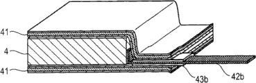
Fig. 4 is the cutaway view of the nonaqueous electrolyte battery got of the line L along Fig. 3.As shown in Figure 4, cell device 4 is contained in the stacked film 41.The negative electrode lead-in wire 42b that is connected to cell device 4 extends to stacked film 41 outsides, makes its part be exposed to stacked film 41 outsides.Sealant 43b is arranged on the part on two surfaces of negative electrode lead-in wire 42b.Negative electrode lead-in wire 42b is sandwiched between laminated film 41 and the following stacked film 41 through sealant 43b.42a is identical with the situation of sealant 43a for the positive electrode lead-in wire.
Fig. 5 illustrates the cross-section structure of stacked film 41.Beyond stacked film 41 is configured in resin molding 41a, metal forming 41b and the bonding usefulness resin molding 41c according to from the outside towards the sequential cascade of cell device 4.
For example aluminium etc. can be used as metal forming 41b.The material that is used for metal forming 41b is not limited to aluminium, but can adopt the material of having mentioned in the correlation technique.Metal forming 41b has the function that improves stacked film 41 intensity and prevents that moisture, oxygen and light from getting into and the function of protection content.
Outer resin molding 41a by have good appearance, roughness and flexible nylon (Ny), polyethylene terephthalate (PET) is processed.Also can select and use various kinds of resin.Shown in outer resin molding 41a is not limited to.Usually, can adopt fusing point to be higher than the material of adhering resin.Resin molding 41c in the bonding usefulness below will be described.
In the manufacture process of nonaqueous electrolyte battery, at first, the both sides except that the bending side of stacked film 41 are fused-and bonding, a remaining side becomes peristome, and the contact conductor 42 that is connected to cell device 4 extends to stacked film 41 outsides from peristome.After this, peristome is through welding-bonding sealing.
Be sandwiched in the part place of the peristome between the stacked on top of one another film 41 at contact conductor 42, the interior resin molding 41c that is used for bonding stacked on top of one another film 41 against each other.In addition, be sandwiched in the part place of the peristome between the stacked on top of one another film 41, form following structure: 43/ time stacked film 41 of sealant 43/ contact conductor, 42/ lower seal layer on the laminated film 41/ at contact conductor 42.Particularly, form following structure: go up outer resin molding 41a/ and go up metal forming 41b/ and go up in the bonding usefulness resin molding 41c/ and go up in 43/ time bonding usefulness of sealant 43/ contact conductor, 42/ lower seal layer under the resin molding 41c/ outer resin molding 41a under the metal forming 41b/.
If peristome is fused-bonding, be arranged as in the bonding usefulness respect to one another resin molding 41c by bonded to each other.Be sandwiched in the part place between the stacked on top of one another film 41 at contact conductor 42, sealant 43 is adhered to contact conductor 42.Sealant 43 is adhered to resin molding 41c in the bonding usefulness.Resin molding 41c is adhered to contact conductor 42 through sealant 43 in the bonding usefulness.
< structure of sealant 43 and the interior resin molding 41c of bonding usefulness >
In the battery pack according to first embodiment, sealant 43 is processed by the following stated heat bonding resin material with the interior resin molding 41c of bonding usefulness.From hereinafter, will specify the heat bonding resin material.
< heat bonding resin material >
The heat bonding resin material comprises heat bonding resin and thin resin fibre.
< heat bonding resin >
Can use and have low-melting relatively resin (for example fusing point is equal to or less than 170 ℃ resin) as the heat bonding resin.Polyolefin resin, for example polyethylene (PE) or polypropylene (PP) etc. can suitably be used as the heat bonding resin.Further, can use TPX (polymethylpentene polymer) etc.Material shown in the heat bonding resin is not limited to.
< thin resin fibre >
Thin resin fibre is meant that diameter for example is equal to or less than the linear structure of the elongation of 100 μ m.The section shape of thin resin fibre is specifically restriction not, and the section of this thin resin fibre can be circle, ellipse or rectangle.The example of thin resin fibre comprises polyethylene terephthalate (PET), polybutylene terephthalate (PBT) (PBT), nylon, aromatic polyamides (aramid), Merlon (PC), polyimides (PI), polyphenylene oxide, PPSU (PPS, polyphenylene sulfone) and polytetrafluoroethylene (PTFE) etc.Material shown in thin resin fibre is not limited to.
The diameter of thin resin fibre is preferably 0.1 μ m to 50 μ m, and more preferably 0.5 μ m is to 20 μ m.Further, the diameter of thin resin fibre should be less than film thickness.For example the diameter of thin resin fibre preferably is equal to or less than the half the of film thickness.This is for necessary heat bonding resin is absorbed in sealing around thin resin fibre.Preferably the heat bonding resin is present on the thickness direction.
The length of thin resin fibre is preferably 50 μ m to 10000 μ m, and more preferably, 200 μ m are to 5000 μ m.If thin resin fibre is too short, the minimizing that interweaves between the thin resin fibre, thin resin fibre moves with resin flow in welding-adhesion process, and this has reduced the resistance for short circuit.Particularly, if use level is little, further reduce to the resistance of short circuit.If thin resin fibre is long, fluffing can appear when forming film.For obtaining outstanding performance, importantly the size with thin resin fibre is arranged in the suitable scope, and forms accurate nonwoven fabrics state through interweaving between the thin resin fibre.
Through observing, obtain the size of thin resin fibre by the diameter of measuring predetermined quantity (the for example 30) fiber of selecting at interval and length and calculating mean value with SEM (scanning electron microscopy).When fibre profile was shaped as circle, circular diameter became the diameter of thin resin fibre.When the section shape of fiber when being non-circular, the maximum gauge of section shape is a diameter.The length of fiber is fiber length in the axial direction.
If the use level of thin resin fibre is excessive, identical characteristic trends towards deterioration in the problem during with the following nonwoven fabrics of employing.If use level is too small, resin thickness is tending towards because of resin flow reduces, and metal forming contacts with each other, and this causes short circuit.
When the diameter or the bond length of thin resin fibre is r μ m, when film thickness was t μ m, the volume ratio that the use level of thin resin fibre is set to the relatively hot adhering resin was equal to or less than (r/t) * 100vol%.The use level of thin resin fibre be thin resin fibre on axial direction with vertical direction on the thickness direction of total amount and film of horizontal area on the use level of area of section when roughly consistent.
The diameter of thin resin fibre obtains through measuring with identical as stated method.Through observing with SEM (scanning electron microscopy), by measure predetermined quantity (the for example 30) fiber selected at interval axially with vertical on fiber width maximum and calculating mean value and obtain the bond length of thin resin fibre.
As stated, the diameter of thin resin fibre should be less than film thickness, and preferably the diameter of thin resin fibre is equal to or less than the half the of film thickness.If it is too small that the diameter of thin resin fibre is compared thickness, then the resistance for short circuit worsens.For this reason, the diameter of thin resin fibre is preferably more than 10% of thickness.The bond length of thin resin fibre also is like this.
The film thickness t (μ m) and the preference relation between diameter or the bond length r (μ m) of thin resin fibre are 0.1t (μ m)<r (μ m)≤0.5t (μ m).Under this condition [0.1t (μ m)<r (μ m)≤0.5t (μ m)], the preferred upper limit of the use level of the thin resin fibre that is calculated by expression formula (r/t) * 100vol% is that the volume ratio of relatively hot adhering resin is greater than 10vol% and be equal to or less than 50vol%.
Consider good characteristic, the concrete preferable range of the use level of thin resin fibre is that the relatively hot adhering resin arrives 25vol% at 10vol% on volume ratio.
In above-mentioned nonaqueous electrolyte battery according to first embodiment of the invention; Be fused at 42 extended peristomes of contact conductor-be easy to when bonding and realize control, and viscosity and sealed nature that 42 extended peristomes of contact conductor can be outstanding be fused-bonding.Further, in the nonaqueous electrolyte battery according to first embodiment of the invention, between metal forming 41b and the contact conductor 42 short circuit appears in the time of can suppressing welding-bonding.
< with correlation technique different >
Be the nonaqueous electrolyte battery of easy to understand, the outstanding effect that will compare with correlation technique according to first embodiment of the invention with reference to description of Related Art according to first embodiment of the invention.
As with the correlation technique that solves same problem according to the nonaqueous electrolyte battery of first embodiment of the invention; Provide following two kinds of methods as an example: the method for the film that is made up of heat bonding resin penetration nonwoven fabrics is adopted in (1), and the method for inorganic filler is added in (2).
< problem of the method for the film of (1) employing heat bonding resin penetration nonwoven fabrics >
According to technology (1), thickness or shape after the sealing are controlled by nonwoven fabrics, so even also be difficult to reduce the resin thickness of nonwoven fabrics after the sealing.The thickness of heat bonding resin bed is equal to or greater than the thickness of nonwoven fabrics, and this thickness is compared with the film that only is formed from a resin and lacked elasticity.Mutually stacked and when being heated when film, use the resin part beyond the nonwoven fabrics, therefore must cover an amount of resin.Therefore, if use nonwoven fabrics, the utilization rate of resin is low, and thickness is greater than the film of only being processed by the heat bonding resin.
Common heat seal is difficult to make the nonwoven fabrics distortion, therefore is difficult to control sealing shape.Exert pressure if at high temperature remove, then nonwoven fabrics recovers its thickness, this feasible thickness that is difficult to control hermetic unit because of elasticity behind heat seal.Further, must let the heat bonding resin penetration in the hole of nonwoven fabrics.If permeate insufficient, entrained air bubble then, gas expands when heat seal, this causes defective sealing or defective outward appearance.Resin flow can be restricted during sealing, makes resin not flow freely, and this can cause film to separate, and promptly peels off (delamination).When film forming, be applicable to that mainly the heat bonding resin is applied to the method for nonwoven fabrics under molten condition, the method for other film forming is difficult to adopt.Laminating method when forming stacked film also is restricted.
< problem of the method for inorganic filler is added in (2) >
According to technology (2), be suitable for and the identical film build method of heat bonding resin that is used to comprise thin resin fibre, but when the moulding stacked film, the sliding property variation between mould and the film, moulding character descends.The moulding machine is swiped probably, and this can cause frequent maintenance.During heat seal, the high heat capacity loss of seal of inorganic filler heat.Therefore, strict condition must be set, and therefore possibly damage stacked film.Hot supply must be increased, therefore when heat supply variation is very little,, defective sealing maybe be occurred because inadequate bonding.If filler is peeled off or separated from film, polluting can appear in inside battery, reduces battery security.
< according to the effect of the nonaqueous electrolyte battery of first embodiment of the invention >
In the nonaqueous electrolyte battery according to first embodiment of the invention, resin molding 41c is processed by the heat bonding resin material in the sealant 43a of stacked film 41 and 43b and the bonding usefulness, and wherein thin resin fibre is added to the heat bonding resin.Therefore, can solve problem intrinsic in the correlation technique.That is, in nonaqueous electrolyte battery, can effectively increase the minimum that is used to prevent short circuit according to first embodiment of the invention.Thin resin fibre itself is not interfered with the heat bonding resin flow, and the heat bonding resin has common resinous principle with thin resin fibre.Therefore, compatibility is good, and different with inorganic filler, and the situation of separation can not occur.Even the heat bonding resin separates with thin resin fibre and gets into inside battery, because they are softer than inorganic filler, also almost not influence in fail safe.
In the nonaqueous electrolyte battery according to first embodiment, the thermal capacity of thin resin fibre and the thermal capacity of heat bonding resin have no difference, and the thermal capacity during heat seal is controlled and only do not compared not variation with the situation of heat bonding resin.For moulding character, the situation of the sliding variation of resin can not appear, thereby and the fine fibre die surface of not swiping firmly, compare maintenance etc. with the situation of only using the heat bonding resin constant.
In nonaqueous electrolyte battery, in order to make the film of processing by the heat bonding resin material, resin molding 41c or sealant 43a and 43b in the for example bonding usefulness, the applicable various film build methods that proposed according to first embodiment of the invention.
For example, the heat bonding resin material that comprises heat bonding resin and thin resin fibre can be through melt extruding method, and for example T modulus method or inflation (inflation) method etc. forms the shape of film.
Briefly, thus melt extruding method is that the material of fusion in the extruder is by being extruded from the mould that is attached to the extruder front end and cooling moulding film forming.The T modulus method be from the wide and flat mould that attaches to the extruder front end (T mould) thus the flat melted material extruded in the roller cooling and reel and form a kind of method of film.
Inflation method is that melted material is extruded with tubular from annular circle mould, thereby expand into preliminary dimension, cools off and be wound on formation film on the roller through in pipe, blowing air.
The shape that can be through the coextrusion method that adopts inflation method or T modulus method the heat bonding resin material be formed film.The coextrusion method is a kind of method that melt extrudes, and is stacked mutually thereby wherein multiple material is once extruded.With this coextrusion method, can form one deck for example and comprise the duplicature that thin resin fibre and one deck do not comprise thin resin fibre.
For example, in above-mentioned first embodiment, replace resin molding 41c in the bonding usefulness, can use one deck by the manufacturing of coextrusion method to comprise the duplicature that thin resin fibre and one deck do not comprise thin resin fibre.Certainly, can adopt this duplicature to replace sealant 43a and 43b.
For example, through the melting heat adhering resin, thin resin fibre is added to the heat bonding resin, and stirs, can obtain the resin melt that thin resin fibre wherein evenly cooperates.The heat bonding resin material can form the shape of film through melt extruding method by resin melt with a step.
Similar with stacked film 41, to the laminating method that is used to make stacked film with a plurality of layers, the applicable various methods that proposed.The example of the method that has proposed comprises to be done range upon range of, heat lamination or extrudes coating etc.
2. second embodiment
< structure of battery pack >
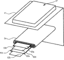
Fig. 6 is the decomposition diagram that illustrates according to the structure of the battery pack of second embodiment of the invention.This battery pack is the battery pack that the lithium ion polymer secondary cell of angular shape or flat pattern is for example arranged.As shown in Figure 6, this battery pack is configured such that cell device 4 is covered by external packing 1, and top cover 2 engages with openings at two ends respectively with bottom 3.Top cover 2 provides opening 21, and the contact portion that is contained in the circuit board in the top cover 2 is passed through opening 21 towards the outside.From hereinafter, the opening that top cover 2 is engaged is known as open top, and the opening that bottom 3 is engaged is known as bottom side openings.
From hereinafter, cell device 4, external packing 1, top cover 2 and bottom 3 will be described.
< cell device 4 >
The structure of cell device 4 is identical with first embodiment, therefore with detailed.
< external packing 1 >
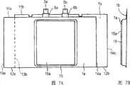
Fig. 7 A is the expanded view of shape that the external packing 1 of clad battery element 4 is shown to 7C.Shown in Fig. 7 A, external packing 1 is made up of soft stacked film 1a and hard stacked film 1b, and wherein soft stacked film 1a is provided with the housing department 15 that is used for closing battery element 4, thereby hard stacked film 1b covers soft stacked film 1a covering shell portion 15.Heat bonding sheet 15a is arranged on the outer surface, is positioned at and corresponding position, the bottom surface of housing department 15.The housing department 15 that is arranged among the soft stacked film 1a is handled the corresponding recess of shape that forms with cell device 4 through for example carrying out punching press (drawing) in advance with mould.
Soft stacked film 1a is suitable for handling the housing department 15 that formation supplies battery element 4 to insert wherein through punching press, and softer than hard stacked film 1b.
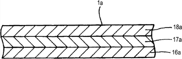
Fig. 8 A is the cutaway view that the example of structure of the soft stacked film 1a that constitutes external packing 1 is shown.Soft stacked film 1a has the stepped construction of blocks moisture and insulation, wherein range upon range of in order adhesive linkage 16a, metal level 17a and sealer 18a, and sealer 18a contacts with hard stacked film 1b.
Adhesive linkage 16a is processed by the heat bonding resin material described in first embodiment, and is identical and no longer repeat among the detailed description of heat bonding resin material and first embodiment.The thickness of adhesive linkage 16a is that for example about 10 μ m are to 30 μ m.
Metal level 17a is processed by softer metals, thereby and has raising external packing intensity and prevent that moisture, oxygen and light from getting into the function of protection content.Consider light and handy, tensile property, cost and ease of processing, aluminium is suitable as softer metals most, especially uses 8021O or the such aluminium of 8079O based on the JIS standard.The thickness of metal level 17a is that for example about 30 μ m are to 130 μ m.
Sealer 18a has the function of surface protection.Consider good surface appearance, roughness and pliability etc., can adopt polyolefin resin, polyamide, polyamide-based resins or polyester etc.Particularly, can adopt nylon (Ny), polyethylene terephthalate (PET), PEN (PEN) polybutylene terephthalate (PBT) (PBT) or PBN (PBN), and can select and use multiple material.Sealer 18a for example has 10 μ m to the thickness of 30 μ m.
Fig. 8 B is the cutaway view of the example of structure of hard stacked film 1b.Hard stacked film 1b can keep shape after bending, and can bear the deformation from the outside.Hard stacked film 1b has adhesive linkage 16b, metal level 17b and the range upon range of in order stepped construction of sealer 18b.
The adhesive linkage 16b of hard stacked film 1b is identical with soft stacked film 1a with sealer 18b.Metal level 17b is processed by for example hard metal material, especially uses aluminium, for example based on the 3003H18 or the such aluminium of 3004H18 of JIS standard.Every layer the thickness of soft stacked film 1a and hard stacked film 1b is suitably selected according to gross thickness.
Thereby the open surfaces of hard stacked film 1b and the stacked covering shell of soft stacked film 1a portion 15.In this case, shown in Fig. 7 A, the position relation between soft stacked film 1a and the hard stacked film 1b departs from.Soft stacked film 1a has the long limit 11a in the identical top side of length and long limit 12a in bottom side and identical left side minor face 13a and the right side minor face 14a of length.Similarly, hard stacked film 1b has the long limit 11b in the identical top side of length and long limit 12b in bottom side and identical left side minor face 13b and the right side minor face 14b of length.About statement represent the position relation when accompanying drawing is observed.
The long limit 11b of hard stacked film 1b and the length of 12b makes under the situation that the housing department that holds cell device 4 15 is closed, and minor face 13b and 14b contact with each other or with a small gaps against each other.The long limit 11b that is shorter in length than hard stacked film 1b of the long limit 11a of soft stacked film 1a and 12a and the length of 12b.For example, the length of the long limit 11a of soft stacked film 1a and 12a makes under the situation that the housing department that holds cell device 4 15 is closed minor face 13a and 14a contacts with each other or with a small gaps against each other.Slit among the soft stacked film 1a is not limited to small gaps, but can be certain width.
The minor face 13a of soft stacked film 1a and 14a slightly are shorter than minor face 13b and the 14b of hard stacked film 1b.Therefore, soft stacked film 1a can be had only hard stacked film 1b to be present in the top side by range upon range made from hard stacked film 1b.When this situation occurring, the outer surface that is arranged on the top cover 2 of open top can be by the adhesive linkage 16b welding of hard stacked film 1b-bonding.In the bottom side, the adhesive linkage 16b of hard stacked film 1b can be exposed makes the adhesive linkage 16b welding that the outer surface of the bottom 3 that is arranged on bottom side openings can be through hard stacked film 1b-bonding.
< top cover >
Thereby top cover 2 engages closed open top with the open top of external packing 1.Top cover 2 is provided with circuit board, and the contact conductor 5a and the 5b that draw from cell device 4 are connected to circuit board.
Comprise that for example fuse, PTC or thermistor etc. and the protective circuit that is used for the ID resistance etc. of identification battery pack are installed in circuit board to temperature protection component.A plurality of (for example three) contact portion is arranged in the circuit board.Protective circuit also comprises IC and the charge/discharge control FET that is used to keep watch on secondary cell and control FET (field-effect transistor).
PTC is connected in series to cell device 4.If the temperature of cell device 4 is higher than temperature is set, the resistance of PTC increases suddenly, thereby cuts off the electric current that flows in the battery basically.Fuse and thermistor also are series at cell device 4, if the temperature of cell device 4 is higher than temperature are set, and cut off the electric current that flows in the battery.
Comprise the IC that is used for monitoring battery element 4 and control FET and the voltage of the protective circuit monitoring battery element 4 of charge/discharge control FET, and if the voltage of cell device 4 surpass 4.3V to 4.4V, thereby then charge closing control FET forbids charging.The protection battery is also kept watch on the voltage of secondary cell, and if the voltage of secondary cell drop to and being lower than discharge and forbidding voltage, forbid discharge thereby then close discharge control FET.
<bottom >
Bottom 3 is arranged on the resin moulded lid of battery floor side end surface.Bottom 3 engages with external packing 1 peristome of formation when battery unit (battery cell) covers with external packing 1, and adheres to battery unit through welding-bonding etc.
< making the method for battery pack >
With the method for explanation according to the manufacturing battery pack of second embodiment of the invention.
< making cell device 4 steps >
At first, has the positive electrode that is formed on two lip-deep gel electrolyte layer and negative electrode and separator sequential cascade by negative electrode, separator and positive electrode.This laminates in the vertical the winding flat core repeatedly, thereby make convoluted cell device 4.
< external packing applying step >
Next, the housing department 15 that is used for closing battery element 4 is molded into soft stacked film 1a through for example deep draw moulding.In this case, shown in Fig. 7 A, the housing department 15 of soft stacked film 1a forms the slight right from the center.Cell device 4 is contained in the housing department 15 that is formed among the soft stacked film 1a.
Next, shown in Fig. 7 A, the hard soft relatively stacked film 1a of stacked film 1b is layered in the position that slightly takes over.Like this, under soft stacked film 1a and the range upon range of state of hard stacked film 1b, shown in Fig. 7 A, occur having only soft stacked film 1a zone, a left side, have only the right zone of hard stacked film 1b.
The reason that depart from as stated the position is after the end of soft stacked film 1a and hard stacked film 1b bends outwards from the bottom surface of housing department 15, can make the adhesive linkage 16a of soft stacked film 1a and the adhesive linkage 16b certain width adhering to each other of hard stacked film 1b.
Next, under the state of the arrangement relation shown in Fig. 7 A, outer four sides of placing of the opening of housing department 15 the decompression in be fused-bonding.In this case, adhesive linkage 16a and adhesive linkage 16b mutually stacked entire portion can be fused-bonding.By this way, the periphery of housing department 15 is fused-and bonding, thus sealed cell element 4.
Next, shown in Fig. 7 A, the heat bonding sheet 15a with reservation shape is arranged on the outside of the bottom surface of housing department 15.Heat bonding sheet 15a is the accessory that is used for coming through heating the sealer 18a of welding-bonding soft stacked film 1a.Preferably, use relative gross thickness to have about 10 μ m to 60 μ m thickness and have the heat bonding sheet 15a of about 100 ℃ fusing point.Heat bonding sheet 15a preferably has the fusing point that the heat of making does not influence cell device 4.
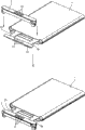
Next, as shown in Figure 9, two ends, minor face 13a and the 14b of soft stacked film 1a and hard stacked film 1b and minor face 13b and 14b curve inwardly towards the outside of the bottom surface of the housing department 15 of soft stacked film 1a.Then, soft stacked film 1a is fused with the end of hard stacked film 1b-and bonding, soft stacked film 1a is fused-is adhered to the outside of the bottom surface of housing department 15.Like this, under the closure state that the housing department that holds cell device 4 15 is closed, soft stacked film 1a and hard stacked film 1b are fixed.That is, form open top and bottom side openings.
Shown in Figure 10 A, under the packed situation of cell device 4, the minor face 13b of hard stacked film 1b and 14b contacts with each other or its end face with a slit against each other, tie point L1 appears.Inner at hard stacked film 1b, the minor face 13a of soft stacked film 1a and 14a contacts with each other or its end face with a slit against each other, tie point L2 appears.
The minor face 13a of soft stacked film 1a is shown Figure 10 A and 14a contacts with each other or its end face example respect to one another.The minor face 13a of soft stacked film 1a and 14a can be under the situation in the slit that certain width is arranged against each other.
Shown in Figure 10 A, the sealer 18a of soft stacked film 1a is positioned to the last side contacts with heat bonding sheet 15a.Thus, heat bonding sheet 15a is sandwiched between the sealer 18a, so sealer 18a can be bonded to each other through apply heat from the outside.The adhesive linkage 16a of soft stacked film 1a and hard stacked film 1b also contacts with adhesive linkage 16b against each other, makes that adhesive linkage 16a and 16b can be bonded to each other through apply heat from the outside.
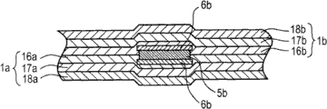
Shown in the cutaway view of Figure 10 B, sealant 6b is provided on the both sides of negative electrode lead-in wire 5b, and negative electrode lead-in wire 5b is clipped between soft stacked film 1a and the hard stacked film 1b through sealant 6b.Particularly, negative electrode lead-in wire 5b is clipped in through sealant 6b between the adhesive linkage 16b of the adhesive linkage 16a of soft stacked film 1a and stacked film 1b firmly.Figure 10 B is the cutaway view that the line P along Fig. 9 gets.Sealant 6b is processed by above-mentioned heat bonding resin material.Sealant 6a situation for being provided on the contact conductor 5a both sides is also identical.
So, can make a kind of battery pack, wherein stacked film also plays the effect of external packing, and the box-like housing that need not be formed from a resin not be used in the framework that both sides arrange that resin is processed.
< top cover engagement step >
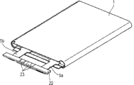
Next, shown in figure 11, contact conductor 5a and 5b are connected to circuit board 22 through for example electric resistance welding or ultrasonic bond.Next, shown in figure 12, circuit board 22 is inserted into the open surfaces of top cover 2, thereby top cover 2 is attached to circuit board 22 covering boards 22.Top cover 2 is the resin moulded products through formation such as for example independent injection mouldings.
Thereby retaining part horizontal holder circuit plate 22 is set on top cover 2.At the top surface of top cover 2, three openings 21 are set in contact portion 23 corresponding positions with circuit board 22.Contact portion 23 faces the outside through opening 21.Top cover 2 is arranged to the inside dimensions of the height of the opening on the top side end face that width is slightly less than external packing 1.
Next, shown in figure 13, retainer 24 and top cover 2 combinations.Retainer 24 is by the for example product of the independent resin moulded manufacturing of injection moulding.Rib 25a, 25b and 25c are separately positioned on the two ends and the center of retainer 24, thereby outstanding towards top cover 2.The end face of rib 25a, 25b and 25c becomes the surface that in top cover 2, is used for circuit board for receiving 22, so circuit board 22 can be by secure support.
Next, shown in the arrow of Figure 14, top cover 2 that engages one another and retainer 24 usefulness hands or anchor clamps revolve in the counterclockwise direction and turn 90 degrees.Therefore, the circuit board 22 of horizontal positioned is vertically placed.In this case, circuit board 22 is sandwiched between top cover 2 and the retainer 24 and not to exposing outside, and makes under the situation of contact circuit plate 22 not, to be rotated.
Next, shown in figure 15, top cover 2 is promoted (at arrow S towards open top with retainer 24
1Direction on), simultaneously meander electrode lead-in wire 5a and 5b.So, top cover 2 engages with open top with retainer 24.As stated, the width of top cover 2 is slightly less than the inside dimensions of opening, makes top cover 2 be clipped at circuit board 22 with retainer 24 and is accommodated under the situation between the two in the space that is limited the hard stacked film 1b around external packing 1 end face.
<bottom engagement step >
Next, shown in figure 15, the sidewall of bottom 3 by towards the opening pushing of the bottom side end face of external packing 1 (at arrow S
2Direction on).So, the sidewall of bottom 3 engages with bottom side openings, and bottom side openings is covered by the main body of bottom 3.Bottom 3 is the resin moulded products by manufacturings such as for example independent injection mouldings.
< welding-adhesion step >
Next, on whole length, carry out welding-bonding through anchor clamps.That is, by metal, for example the heater module processed such as copper vertically is pressed in around the top side end of external packing 1, thus the outer surface of welding-bonding top cover 2 and as the adhesive linkage 16b of hard stacked film 1b inner surface.Similarly, heater module can vertically be pressed in around the bottom side end of external packing 1, thus the adhesive linkage 16b of the outer surface of welding-bonding bottom 3 and the hard stacked film 1b inner surface of conduct.
< resin injection step >
Next, molten resin (hot melt material) is filled between cell device 4 and the bottom 3 through the through hole (not shown) that is arranged on bottom 3 and solidifies.So, bottom 3 adheres to the end face of cell device 4.The resin of being filled can be in low viscous state when moulding.Can adopt polyamide-based hot melt, polyolefin-based hot melt body or acrylonitrile butadiene copolymer (ABS) etc., but not special restriction.
Molten resin can be filled between top cover 2 and the cell device 4.In this case, one or two through hole can be arranged in the top cover 2, and molten resin can inject from this through hole.Through above-mentioned steps, make battery pack according to a second embodiment of the present invention.
In battery pack according to a second embodiment of the present invention, can obtain the effect identical with first embodiment.
3. the 3rd embodiment
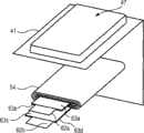
Figure 16 and 17 illustrates the structure according to the nonaqueous electrolyte battery of third embodiment of the invention.Shown in Figure 16 and 17, nonaqueous electrolyte battery has the cell device 54 that is contained in the recess 47 that is formed in the stacked film 41 and seals through three sides except the bending side on the periphery of welding under reduced pressure-bonding cell device 54.
Shown in figure 17, nonaqueous electrolyte battery is configured such that the positive electrode lead-in wire 62a and the negative electrode lead-in wire 62b that are connected respectively to positive electrode and negative electrode extend to the outside from the sealing of stacked film 41 on equidirectional.Positive electrode lead-in wire 62a and negative electrode lead-in wire 62b are fit to be called as contact conductor in the time needn't distinguishing.
< cell device 54 >
Cell device 54 has angular shape or flat pattern is for example arranged, and it is configured such that banded positive electrode and banded negative electrode pass through polymer dielectric and/or separator is range upon range of, and reels in the vertical.The positive electrode lead-in wire 62a that is processed by for example aluminium (Al) etc. is connected to positive electrode.The negative electrode lead-in wire 62b that is processed by for example nickel (Ni) etc. is connected to negative electrode.
Positive electrode lead-in wire 62a and negative electrode lead-in wire 62b have big width.Positive electrode lead-in wire 62a has identical width with negative electrode lead-in wire 62b.Contact conductor with big width is suitable for carrying out the battery of heavy-current discharge.Through the big width of contact conductor, the resistance when big electric current flows can reduce, and the heat that contact conductor produces can reduce.
Positive electrode lead-in wire 62a and the negative electrode 62b that goes between preferably has 50% the width that is equal to or greater than cell device 54 width.If the width of positive electrode lead-in wire 62a and negative electrode lead-in wire 62b is less than 50% of cell device 54 width, resistance can increase when big electric current flowed, and because defective can appear in heating.Positive electrode lead-in wire 62a and negative electrode 95% the width that 62b preferably has the cell widths of being equal to or less than that goes between.If the width of positive electrode lead-in wire 62a and negative electrode lead-in wire 62b occurs defective less than 95% of cell device 54 width at hermetic unit easily.
Positive electrode lead-in wire 62a is different with the length of negative electrode lead-in wire 62b.Particularly, the length that is shorter in length than negative electrode lead-in wire 62b of positive electrode lead-in wire 62a.
Sealant 63a to 63d by as above processing with the heat bonding resin material of thin resin fibre at the adhering resin that comprises described in first embodiment.
Sealant 63a is arranged in the part surface of positive electrode lead-in wire 62a in the face of stacked film 41, thereby improves bonding with stacked film 41.Sealant 63b is arranged in the part surface of positive electrode lead-in wire 62a in the face of negative electrode lead-in wire 62b.Sealant 63a and sealant 63b are bonded to each other.
Sealant 63d is arranged in negative electrode lead-in wire 62b in the face of on a part of surface of stacked film 41, thereby raising and stacked film 41 is bonding.Sealant 63c is arranged in the part surface of negative electrode lead-in wire 62b in the face of positive electrode lead-in wire 62a.Sealant 63c and sealant 63d are bonded to each other.Thereby arrange sealant 63b and sealant 63c inhibition short circuit to occur because positive electrode lead-in wire 62a directly contacts mutually with negative electrode lead-in wire 62b.Sealant 63b and sealant 63c are bonded to each other.
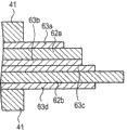
Figure 18 illustrates the cross-section structure of being got along the line a-a ' of Figure 17.Shown in figure 18, the identical positive electrode of width lead-in wire 62a and the negative electrode 62b that goes between is arranged to that their other end is in identical position on their end and the Width on the Width.Sealant 63b and sealant 63c are arranged between positive electrode lead-in wire 62a and the negative electrode lead-in wire 62b.So, positive electrode lead-in wire 62a is stacked mutually on the cell thickness direction through sealant 63b and sealant 63c in the face of the surface of positive electrode lead-in wire 62a in the face of surface and the negative electrode lead-in wire 62b of negative electrode lead-in wire 62b.
Be not clipped in the part between the stacked on top of one another film 41 at positive electrode lead-in wire 62a and negative electrode lead-in wire 62b, resin molding 41c against each other in the bonding usefulness of stacked on top of one another film 41.Be not clipped in the part between the stacked on top of one another film 41 at positive electrode lead-in wire 62a and negative electrode lead-in wire 62b, resin molding 41c through sealant 63a and 63d against each other in the bonding usefulness of stacked on top of one another film 41.
Be clipped in the part between the stacked on top of one another film 41 at positive electrode lead-in wire 62a and negative electrode lead-in wire 62b, be configured to following structure: stacked film 41 under the laminated film 41/ sealant 63a/ positive electrode lead-in wire 62a/ sealant 63b/ sealant 63c/ negative electrode lead-in wire 62b/ sealant 63d/.Particularly, be configured to following structure: go up outer resin molding 41a/ and go up metal forming 41b/ and go up in the bonding usefulness under the resin molding 41c/ sealant 63a/ positive electrode lead-in wire 62a/ sealant 63b/ sealant 63c/ negative electrode lead-in wire 62b/ sealant 63d/ in the bonding usefulness under the resin molding 41c/ outer resin molding 41a under the metal forming 41b/.
Resin molding 41c is bonded to each other in the relative bonding usefulness.To 63d part respect to one another, resin molding 41c is bonded to each other in the relative bonding usefulness through sealant 63a for resin molding 41c in bonding usefulness.
Sealant 63a is adhered to positive electrode lead-in wire 62a.Resin molding 41c is bonded to each other in sealant 63a and the last bonding usefulness.Go up the interior resin molding 41c of bonding usefulness and be adhered to positive electrode lead-in wire 62a through sealant 63a.
Sealant 63d is adhered to negative electrode lead-in wire 62b.Sealant 63d is with the interior resin molding 41c of bonding usefulness is bonded to each other down.Resin molding 41c is adhered to negative electrode lead-in wire 62b through sealant 63d in the bonding usefulness down.Sealant 63b and sealant 63c are bonded to each other.Sealant 63b is adhered to negative electrode lead-in wire 62b through sealant 63c.Sealant 63c is adhered to positive electrode lead-in wire 62a through sealant 63b.
Figure 19 A is the vertical view that illustrates from stacked film 41 extended positive electrode lead-in wire 62a, negative electrode lead-in wire 62b and sealant 63a to the structure of the extension of 63d.Figure 19 B is the cutaway view that the line b-b ' along Figure 19 A gets.
Shown in Figure 19 A and 19B, positive electrode lead-in wire 62a is different with the extension length of negative electrode lead-in wire 62b.That is, the extension of positive electrode lead-in wire 62a is set to the length weak point than the extension of negative electrode lead-in wire 62b.
The width of two lip-deep sealant 63a and sealant 63b that is arranged in positive electrode lead-in wire 62a is bigger than the go between width of 62a of positive electrode.The extension of sealant 63a and sealant 63b is set to the length of length less than the extension of positive electrode lead-in wire 62a.So, positive electrode lead-in wire 62a has part that is covered by sealant 63a and the part that is not covered by sealant 63a in the face of the surface of sealant 63a.Positive electrode lead-in wire 62a has part that is covered by sealant 63b and the part that is not covered by sealant 63b in the face of the surface of sealant 63b.
The width of two lip-deep sealant 63c and sealant 63d that is arranged in negative electrode lead-in wire 62b is greater than the go between width of 62b of negative electrode.The extension of sealant 63c and sealant 63d is set to length less than the length of the extension of negative electrode lead-in wire 62b and greater than the length of the extension of positive electrode lead-in wire 62a.So, negative electrode lead-in wire 62b has part that is covered by sealant 63c and the part that is not covered by sealant 63c in the face of the surface of sealant 63c.Negative electrode lead-in wire 62b has part that is covered by sealant 63d and the part that is not covered by sealant 63d in the face of the surface of sealant 63d.Negative electrode lead-in wire 62b is not positioned at the outside of positive electrode lead-in wire 62a by the part of sealant 63c and sealant 63d covering.
On the surface of positive electrode lead-in wire 62a, relative through sealant 63b and sealant 63c with negative electrode lead-in wire 62b by the part that sealant 63b covers in the face of sealant 63b.On the surface of positive electrode lead-in wire 62a in the face of sealant 63b, it is relative with negative electrode lead-in wire 62b that the part that is not covered by sealant 63b is passed through sealant 63c.On the surface of negative electrode lead-in wire 62b in the face of sealant 63c, the part that is not covered by sealant 63c is positioned at the positive electrode lead-in wire 62a outside.So, can suppress because positive electrode lead-in wire 62a short circuit occurs with mutual directly contact of negative electrode lead-in wire 62b.Positive electrode lead-in wire 62a has the part that is not covered by sealant 63a and sealant 63b on two surfaces, the area of the exposed portions serve of positive electrode lead-in wire 62a than in the variation of following description greatly, this has realized the higher degree of freedom for the welding position.
< distortion >
(first example)
Can construct as follows to the extension of 63d from stacked film 41 extended positive electrode lead-in wire 62a, negative electrode lead-in wire 62b and sealant 63a.At first, with explanation positive electrode lead-in wire 62a, negative electrode lead-in wire 62b and sealant 63a another first example to the structure of the extension of 63d.Figure 20 A illustrates positive electrode lead-in wire 62a, negative electrode lead-in wire 62b and the sealant 63a vertical view to another first example of the structure of the extension of 63d.Figure 20 B illustrates the cross-section structure of getting along the line c-c ' of Figure 20 A.
Shown in Figure 20 A and 20B, positive electrode lead-in wire 62a is different with the extension length of negative electrode lead-in wire 62b.That is, positive electrode lead-in wire 62a is arranged to the length of length less than negative electrode lead-in wire 62b.
Two lip-deep sealant 63a that are arranged in positive electrode lead-in wire 62a and sealant 63b are set to width greater than the go between width of 62a of positive electrode.The length of length less than the extension of positive electrode lead-in wire 62a is arranged in the extension of sealant 63a.The extension of sealant 63b is set to have the identical length of length with the extension of positive electrode lead-in wire 62a.So, positive electrode lead-in wire 62a has part that is covered by sealant 63a and the part that is not covered by sealant 63a in the face of the surface of sealant 63a.Positive electrode lead-in wire 62a is covered by sealant 63b in the face of the surface of sealant 63b fully.
Two lip-deep sealant 63c that are arranged in negative electrode lead-in wire 62b and sealant 63d are arranged to width greater than the go between width of 62b of negative electrode.The extension of sealant 63c and sealant 63d is configured to the length of length less than the extension of negative electrode lead-in wire 62b, and greater than the length of the extension of positive electrode lead-in wire 62a.So, negative electrode lead-in wire 62b has part that is covered by sealant 63c and the part that is not covered by sealant 63c in the face of the surface of sealant 63c.Negative electrode lead-in wire 62b has part that is covered by sealant 63d and the part that is not covered by sealant 63d in the face of the surface of sealant 63d.Negative electrode lead-in wire 62b is not positioned at the positive electrode lead-in wire 62a outside by the part of sealant 63c and sealant 63d covering.
Positive electrode lead-in wire 62a is relative with negative electrode lead-in wire 62b through sealant 63b and sealant 63c in the face of the surface of sealant 63b.Negative electrode lead-in wire 62b is in the face of on the surface of sealant 63c, and the part that is not covered by sealant 63c is positioned at the positive electrode lead-in wire 62a outside.So, can suppress short circuit to occur because of positive electrode lead-in wire 62a directly contacts mutually with negative electrode lead-in wire 62b.In first example, two sealant 63b and sealant 63c are arranged on the whole zone between positive electrode lead-in wire 62a and the negative electrode lead-in wire 62b, so can suppress short circuit more reliably.
(second example)
Next, with explanation positive electrode lead-in wire 62a, negative electrode lead-in wire 62b and sealant 63a another second example to the extension of 63d.Figure 21 A is the vertical view of another second example that the extension of positive electrode lead-in wire 62a, negative electrode lead-in wire 62b and sealant 63 is shown.Figure 21 B illustrates the cutaway view of getting along the line d-d ' of Figure 21 A.Shown in Figure 21 A and 21B, positive electrode lead-in wire 62a is different with the length of the extension of negative electrode lead-in wire 62b.That is, positive electrode lead-in wire 62a is arranged to the length of length less than negative electrode lead-in wire 62b.
Two lip-deep sealant 63a that are arranged in positive electrode lead-in wire 62a and sealant 63b are set to width greater than the go between width of 62a of positive electrode.The length of length less than the extension of positive electrode lead-in wire 62a is arranged in the extension of sealant 63a.The length of length greater than the extension of positive electrode lead-in wire 62a is arranged in the extension of sealant 63b.So, positive electrode lead-in wire 62a has part that is covered by sealant 63a and the part that is not covered by sealant 63a in the face of the surface of sealant 63a.Positive electrode lead-in wire 62a is covered by sealant 63b in the face of the surface of sealant 63b fully.
Two lip-deep sealant 63c that are arranged in negative electrode lead-in wire 62b and sealant 63d are arranged to width greater than the go between width of 62b of negative electrode.The extension of sealant 63c and sealant 63d be configured to length less than the length of the extension of negative electrode lead-in wire 62b the length greater than the extension of positive electrode lead-in wire 62a.So, negative electrode lead-in wire 62b has part that is covered by sealant 63c and the part that is not covered by sealant 63c in the face of the surface of sealant 63c.Negative electrode lead-in wire 62b has part that is covered by sealant 63d and the part that is not covered by sealant 63d in the face of the surface of sealant 63d.Negative electrode lead-in wire 62b is not positioned at the positive electrode lead-in wire 62a outside by the part of sealant 63c and sealant 63d covering.
Positive electrode lead-in wire 62a is relative with negative electrode lead-in wire 62b through sealant 63b and sealant 63c in the face of the surface of sealant 63b.Negative electrode lead-in wire 62b is in the face of on the surface of sealant 63c, and the part that is not covered by sealant 63c is positioned at the positive electrode lead-in wire 62a outside.Therefore, can suppress short circuit to occur because of positive electrode lead-in wire 62a directly contacts mutually with negative electrode lead-in wire 62b.In second example, two sealant 63b and sealant 63c are arranged on the whole zone between positive electrode lead-in wire 62a and the negative electrode lead-in wire 62b, so can suppress short circuit more reliably.
< effect >
In the nonaqueous electrolyte battery according to third embodiment of the invention, positive electrode lead-in wire 62a and negative electrode lead-in wire 62b are stacked mutually on the thickness direction of battery through sealant 63b and 63c, can obtain good volume energy density thus.
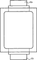
Promptly; When the positive electrode lead-in wire 62a that has a big width when use goes between 62b with negative electrode; If positive electrode lead-in wire 62a and negative electrode lead-in wire 62b extend from the same side of battery, then owing to use positive electrode lead-in wire 62a and the negative electrode lead-in wire 62b with big width, short circuit appears probably.Therefore, in order to suppress short circuit, for example, battery shown in the image pattern 22 is such, and positive electrode lead-in wire 62a and negative electrode lead-in wire 62b never homonymy extend.But if positive electrode lead-in wire 62a and never homonymy extension of negative electrode lead-in wire 62b then must seal positive electrode lead-in wire 62a and the extended both sides of negative electrode lead-in wire 62b, this can cause volume efficiency decline.
Simultaneously, in the nonaqueous electrolyte battery according to third embodiment of the invention, positive electrode lead-in wire 62a and negative electrode lead-in wire 62b extend from the same side of battery.That is, positive electrode lead-in wire 62a and negative electrode lead-in wire 62b extend from a side.So, can reduce the sealing area of the part of positive electrode lead-in wire 62a and negative electrode lead-in wire 62b extension, thereby improve the volume of cell device 54.So, compare battery shown in Figure 22, can improve volume energy density.Further, sealant 63b that the heat bonding resin material of involved heat bonding resin and thin resin fibre is processed and 63c are arranged between positive electrode lead-in wire 62a and the negative electrode lead-in wire 62b, thereby can suppress the appearance of short circuit more reliably.
4. the 4th embodiment
Now the fourth embodiment of the present invention will be described.Except positive electrode lead-in wire 62a and the negative electrode 62b that goes between is having different layouts and the structure, the 4th embodiment is identical with the 3rd embodiment on the width.So, below will concentrate on the different of the 3rd embodiment and be elaborated, no longer repeat other explanation.
Like Figure 23 A and 23B, nonaqueous electrolyte battery has the cell device 54 that is contained in the recess 47 that is formed in the stacked film 41, and is under reduced pressure sealed through outer three sides of placing except that the bending side of welding-bonding cell device 54.Nonaqueous electrolyte battery is configured such that the positive electrode lead-in wire 62a and the negative electrode lead-in wire 62b that are connected to cell device 54 extend to the outside from the hermetic unit of stacked film 41 on equidirectional.The positive electrode lead-in wire 62a that is processed by for example aluminium (Al) etc. is connected to the positive electrode of cell device 54.The negative electrode lead-in wire 62b that is processed by for example nickel (Ni) etc. is connected to the negative electrode of cell device 54.Positive electrode lead-in wire 62a is set to have identical width with negative electrode lead-in wire 62b.
Figure 24 illustrates the section of getting along the line e-e ' of Figure 23 B.Shown in figure 24, positive electrode lead-in wire 62a is in diverse location at the end on the Width and the other end and the negative electrode 62b that goes between at the end on the Width and the other end on Width.Particularly; Positive electrode lead-in wire 62a is positioned at negative electrode lead-in wire 62b end left side on Width at the end on the Width, and positive electrode lead-in wire 62a is present in negative electrode lead-in wire 62b between the end and the other end on the Width at the other end on the Width.Sealant 63b and sealant 63c are arranged between positive electrode lead-in wire 62a and the negative electrode lead-in wire 62b.So, positive electrode lead-in wire 62a is stacked mutually on thickness direction through sealant 63b and sealant 63c in the face of the part on the surface of positive electrode lead-in wire 62a in the face of a part and the negative electrode lead-in wire 62b on the surface of negative electrode lead-in wire 62b.
The part that does not clip positive electrode lead-in wire 62a and negative electrode lead-in wire 62b between stacked on top of one another film 41, resin molding 41c against each other in the bonding usefulness of stacked on top of one another film 41.The part that does not clip positive electrode lead-in wire 62a and negative electrode lead-in wire 62b between stacked on top of one another film 41, resin molding 41c through sealant 63a to 63d against each other in the bonding usefulness of stacked on top of one another film 41.
The part that positive electrode lead-in wire 62a between stacked on top of one another film 41 and negative electrode lead-in wire 62b are clipped is configured to following structure: stacked film 41 under the laminated film 41/ sealant 63a/ positive electrode lead-in wire 62a/ sealant 63b/ sealant 63c/ negative electrode lead-in wire 62b/ sealant 63d/.Particularly, be configured to following structure: go up outer resin molding 41a/ and go up metal forming 41b/ and go up in the bonding usefulness under the resin molding 41c/ sealant 63a/ positive electrode lead-in wire 62a/ sealant 63b/ sealant 63c/ negative electrode lead-in wire 62b/ sealant 63d/ in the bonding usefulness under the resin molding 41c/ outer resin molding 41a under the metal forming 41b/.
The part that clips positive electrode lead-in wire 62a between stacked on top of one another film 41 is configured to following structure: stacked film 41 under the laminated film 41/ sealant 63a/ positive electrode lead-in wire 62a/ sealant 63b/ sealant 63c/ sealant 63d/.Particularly, be configured to following structure: go up outer resin molding 41a/ and go up metal forming 41b/ and go up in the bonding usefulness under the resin molding 41c/ sealant 63a/ positive electrode lead-in wire 62a/ sealant 63b/ sealant 63c/ sealant 63d/ in the bonding usefulness under the resin molding 41c/ outer resin molding 41a under the metal forming 41b/.
The part that clips negative electrode lead-in wire 62b between stacked on top of one another film 41 is configured to following structure: stacked film 41 under the laminated film 41/ sealant 63a/ sealant 63b/ sealant 63c/ negative electrode lead-in wire 62b/ sealant 63d/.Particularly, be configured to following structure: go up outer resin molding 41a/ and go up metal forming 41b/ and go up in the bonding usefulness under the resin molding 41c/ sealant 63a/ sealant 63b/ sealant 63c/ negative electrode lead-in wire 62b/ sealant 63d/ in the bonding usefulness under the resin molding 41c/ outer resin molding 41a under the metal forming 41b/.
Resin molding 41c is bonded to each other in the relative bonding usefulness.To 63d part respect to one another, resin molding 41c is bonded to each other to 63d through sealant 63a bonded to each other in the relative bonding usefulness through sealant 63a for resin molding 41c in bonding usefulness.
Sealant 63a is adhered to positive electrode lead-in wire 62a.Resin molding 41c is bonded to each other in sealant 63a and the last bonding usefulness.Go up the interior resin molding 41c of bonding usefulness and be adhered to positive electrode lead-in wire 62a through sealant 63a.
Sealant 63d is adhered to negative electrode lead-in wire 62b.Sealant 63a is with the interior resin molding 41c of bonding usefulness is bonded to each other down.Resin molding 41c is adhered to negative electrode lead-in wire 62b through sealant 63d in the bonding usefulness down.
Sealant 63b and sealant 63c are bonded to each other.Sealant 63b is adhered to negative electrode lead-in wire 62b through sealant 63c.Sealant 63c is adhered to positive electrode lead-in wire 62a through sealant 63b.
< effect >
Nonaqueous electrolyte battery according to fourth embodiment of the invention has the effect identical with the 3rd embodiment.
5. the 5th embodiment
Now the fifth embodiment of the present invention will be described.Except positive electrode lead-in wire 62a has on Width different layouts and the structure with negative electrode lead-in wire 62b, the 5th embodiment is identical with the 3rd embodiment.So, below will concentrate on the different of the 3rd embodiment and be elaborated, no longer repeat other explanation.
Like Figure 25 A and 25B, nonaqueous electrolyte battery has the cell device 54 that is contained in the recess 47 that forms in the stacked film 41 and is under reduced pressure sealed through outer three sides of placing except that the bending side of welding-bonding cell device 54.
Nonaqueous electrolyte battery is configured such that the positive electrode lead-in wire 62a that is connected to cell device 54 and the negative electrode 62b that goes between extends to the outside from the hermetic unit of stacked film 41 at equidirectional.The positive electrode lead-in wire 62a that is processed by for example aluminium (Al) etc. is connected to the positive electrode of cell device 54.The negative electrode lead-in wire 62b that is processed by for example nickel (Ni) etc. is connected to the negative electrode of cell device 54.Negative electrode lead-in wire 62b is set to the width of width greater than positive electrode lead-in wire 62a.
Figure 26 illustrates the section of getting along the line f-f ' of Figure 23 B.Shown in figure 26, positive electrode lead-in wire 62a and negative electrode lead-in wire 62b are in diverse location at the end on the Width and the other end on Width.Particularly, and positive electrode lead-in wire 62a the end on the Width and the other end at negative electrode lead-in wire 62b between the end and the other end on the Width.Sealant 63b and sealant 63c are arranged between positive electrode lead-in wire 62a and the negative electrode lead-in wire 62b.So, positive electrode lead-in wire 62a is stacked mutually on thickness direction through sealant 63b and sealant 63c in the face of the part on the surface of positive electrode lead-in wire 62a in the face of a part and the negative electrode lead-in wire 62b on the surface of negative electrode lead-in wire 62b.
In example shown in Figure 26, the end on the Width of the negative electrode lead-in wire 62b that appearance changes and the other end are positioned to not stacked with positive electrode lead-in wire 62a on the thickness direction of battery through sealant 63b and 63c.Therefore, when negative electrode lead-in wire 62b by material with big variation, for example nickel (Ni) waits when processing, and can more effectively suppress the short circuit between the 62b that goes between of positive electrode lead-in wire 62a and negative electrode.
The part that does not clip positive electrode lead-in wire 62a and negative electrode lead-in wire 62b between stacked on top of one another film 41, resin molding 41c against each other in the bonding usefulness of stacked on top of one another film 41.In the part that does not clip positive electrode lead-in wire 62a and negative electrode lead-in wire 62b of stacked on top of one another film 41, resin molding 41c through sealant 63a to sealant 63d against each other in the bonding usefulness of stacked on top of one another film 41.
The part that positive electrode lead-in wire 62a between stacked on top of one another film 41 and negative electrode lead-in wire 62b are clipped is configured to following structure: stacked film 41 under the laminated film 41/ sealant 63a/ positive electrode lead-in wire 62a/ sealant 63b/ sealant 63c/ negative electrode lead-in wire 62b/ sealant 63d/.Particularly, be configured to following structure: go up outer resin molding 41a/ and go up metal forming 41b/ and go up in the bonding usefulness under the resin molding 41c/ sealant 63a/ positive electrode lead-in wire 62a/ sealant 63b/ sealant 63c/ negative electrode lead-in wire 62b/ sealant 63d/ in the bonding usefulness under the resin molding 41c/ outer resin molding 41a under the metal forming 41b/.
The part that clips negative electrode lead-in wire 62b between stacked on top of one another film 41 is configured to following structure: stacked film 41 under the laminated film 41/ sealant 63a/ sealant 63b/ sealant 63c/ negative electrode lead-in wire 62b/ sealant 63d/.Particularly, be configured to following structure: go up outer resin molding 41a/ and go up metal forming 41b/ and go up in the bonding usefulness under the resin molding 41c/ sealant 63a/ sealant 63b/ sealant 63c/ negative electrode lead-in wire 62b/ sealant 63d/ in the bonding usefulness under the resin molding 41c/ outer resin molding 41a under the metal forming 41b/.
Resin molding 41c is bonded to each other in the relative bonding usefulness.To 63d part respect to one another, resin molding 41c is bonded to each other to 63d through sealant 63a bonded to each other in the relative bonding usefulness through sealant 63a for resin molding 41c in bonding usefulness.
Sealant 63a is adhered to positive electrode lead-in wire 62a.Resin molding 41c is bonded to each other in sealant 63a and the last bonding usefulness.Go up the interior resin molding 41c of bonding usefulness and be adhered to positive electrode lead-in wire 62a through sealant 63a.
Sealant 63d is adhered to negative electrode lead-in wire 62b.Sealant 63d is with the interior resin molding 41c of bonding usefulness is bonded to each other down.Resin molding 41c is adhered to negative electrode lead-in wire 62b through sealant 63d in the bonding usefulness down.
Sealant 63b and sealant 63c are bonded to each other.Sealant 63b is adhered to negative electrode lead-in wire 62b through sealant 63c.Sealant 63c is adhered to positive electrode lead-in wire 62a through sealant 63b.
< effect >
Nonaqueous electrolyte battery according to fifth embodiment of the invention has the effect identical with the 3rd embodiment.
[example]
< Test Example 1-1 >
Three layers of aluminium stacked film 41 of 10cm * 10cm shown in Figure 6 are made is used for test.With reference to cross-section structure shown in Figure 6, use aluminium stacked film 41, resin molding 41c constructs as stated in wherein outer resin molding 41a, metal forming 41b and the bonding usefulness.
Outer resin molding 41a:PET film
Metal forming 41b: aluminium foil
Resin molding 41c in the bonding usefulness: the un-stretched polypropylene (CPP) that has cooperated the thin resin fibre of 5vol%
The following interior resin molding 41c of bonding usefulness that makes.At first, through fusion un-stretched polypropylene (CPP), add thin resin fibre to un-stretched polypropylene (CPP), and stir, make the resin melt that has wherein evenly cooperated thin resin fibre.The volume ratio of the relative un-stretched polypropylene of use level (CPP) of thin resin fibre is 5vol%.Resin melt forms the film shape through inflation method, thereby obtains resin molding 41c in the bonding usefulness.
The PET fiber that uses diameter 10 μ m, length 500 μ m is as thin resin fibre.When observing with SEM, the diameter of thin resin fibre and length are obtained by the diameter of measuring 30 fibers of selection at interval and length and calculating mean value.
The following aluminium stacked film 41 of making.To two surfaces of the aluminium foil of thickness 50 μ m applied adhesives all, the PET film of thickness 20 μ m is adhered to a surface of aluminium foil, and the un-stretched polypropylene film that is combined with the thickness 30 μ m of the thin resin fibre of 5vol% in it is adhered to the another side of aluminium foil.The thickness of adhesive linkage is 5 μ m.
(peeling strength test)
Utilizing aluminium stacked film 41 to carry out peeling strength measures to be used for test.Prepare also to arrange two aluminium stacked films 41, make un-stretched polypropylene film (CPP) against each other, carry out welding-bonding then.Bond condition be adopt the metallic seal head, on/following 180 ℃, sealing load 20kgf/cm
2, 5 seconds sealing time.
The welding of width 15mm-bonding test block is cut and is removed in the longitudinal direction, and measures peeling strength.In this case, thus the PET adhesive tape is adhered to two surfaces not to be caused resin stretched.Separation condition is 180 ° of separation, separating rate 50mm/min.
(cleavage fracture stress measurement)
Be used for test through adopting aluminium stacked film 41 to make battery with structure shown in Fig. 3.Use 5vol% to cooperate the material that obtains with un-stretched polypropylene (CPP), as go between 42 (the aluminium tab of width 5mm goes between) and have the 8mm * 10mm sealant 43a and the 43b of 50 μ m thickness of coated electrode as the PET fiber of thin resin fibre.
Be described below and make sealant 43a and 43b.At first, through fusion un-stretched polypropylene (CPP), thin resin fibre is added to un-stretched polypropylene (CPP) and stirs the wherein even resin melt that cooperates thin resin fibre of manufacturing.The use level of thin resin fibre is to be the amount of 5vol% corresponding to un-stretched polypropylene (CPP) volume ratio relatively.Resin melt is formed the film shape and with preliminary dimension cutting through inflation method, thereby obtain sealant 43a and 43b.
Battery is configured to use pseudo-element (dummy element) as cell device 4, and pseudo-element is covered by aluminium stacked film 41, and four sides on the pseudo-element periphery are sealed.The air-proof condition of stacked film be to use wide 1mm ferrule, on/following 180 °, sealing load 20kgf/cm
2, 5 seconds sealing time.Next, from pseudo-element injecting compressed air, the pressure when measuring hermetic unit expansion and splitting.
(assessment of moulding character)
Mould with squareness ratio 40mm * 60mm carries out the deep draw processing to aluminium stacked film 41.Moulding speed is 100mm/min.Moulding character is assessed by measuring the minimum-depth that occurs pin hole or crack among the metal forming 41b.
(short circuit affirmation)
Through the battery that uses aluminium stacked film 41 to make to have structure shown in Figure 3 to be used for test.In this case, 8mm * 10mm sealant 43a and 43b of used thickness 50 μ m.Sealant 43a and 43b cooperate the material that obtains to process by the PET fiber of diameter 10 μ m, long 500 μ m with un-stretched polypropylene (CPP).At sealing load 30kgf/cm
2, 200 ℃ of seal temperatures condition under seal 30 seconds, confirm that short circuit has occurred 30 seconds.
< test case 1-2 >
Use the un-stretched polypropylene that wherein is combined with the thin resin fibre of 10vol% as resin molding 41c and sealant 43a and 43b in the bonding usefulness of aluminium stacked film 41.Other is identical with test case 1-1, and tests (1) and arrive (4).
< test case 1-3 >
Use the un-stretched polypropylene (CPP) that wherein is combined with the thin resin fibre of 15vol% as resin molding 41c and sealant 43a and 43b in the bonding usefulness of aluminium stacked film 41.Other is identical with test case 1-1, and tests (1) and arrive (4).
< test case 1-4 >
Use the un-stretched polypropylene (CPP) that wherein is combined with the thin resin fibre of 20vol% as resin molding 41c and sealant 43a and 43b in the bonding usefulness of aluminium stacked film 41.Other is identical with test case 1-1, and tests (1) and arrive (4).
< test case 1-5 >
Use the un-stretched polypropylene (CPP) that wherein is combined with the thin resin fibre of 25vol% as resin molding 41c and sealant 43a and 43b in the bonding usefulness of aluminium stacked film 41.Other is identical with test case 1-1, and tests (1) and arrive (4).
< test case 1-6 >
Use the un-stretched polypropylene (CPP) that wherein is combined with the thin resin fibre of 30vol% as resin molding 41c and sealant 43a and 43b in the bonding usefulness of aluminium stacked film 41.Other is identical with test case 1-1, and tests (1) and arrive (4).
< test case 1-7 >
Use the un-stretched polypropylene (CPP) that wherein is combined with the thin resin fibre of 40vol% as resin molding 41c and sealant 43a and 43b in the bonding usefulness of aluminium stacked film 41.Other is identical with test case 1-1, and tests (1) and arrive (4).
< test case 1-8 >
Use the un-stretched polypropylene (CPP) that wherein is combined with the thin resin fibre of 50vol% as resin molding 41c and sealant 43a and 43b in the bonding usefulness of aluminium stacked film 41.Other is identical with test case 1-1, and tests (1) and arrive (4).
< test case 1-9 >
Use the un-stretched polypropylene (CPP) that wherein is combined with the thin resin fibre of 60vol% as resin molding 41c and sealant 43a and 43b in the bonding usefulness of aluminium stacked film 41.Other is identical with test case 1-1, and tests (1) and arrive (4).
< test case 1-10>(being used for comparison)
Use the un-stretched polypropylene (CPP) that does not cooperate thin resin fibre as resin molding 41c and sealant 43a and 43b in the bonding usefulness of aluminium stacked film 41.Other is identical with test case 1-1, and tests (1) and arrive (4).
Table 1 illustrates the test result of test case 1-1 to test case 1-10.As the result of peeling strength test, the value that is equal to or greater than 25N/15mm is desirable.As the result of splitting test pressure test, the value that is equal to or greater than 0.35Pa is desirable.As moulding character assessment result, the value that is equal to or greater than 5.80mm is desirable.
Table 1
|
|
Addition [vol%] |
Sealing intensity [N/15mm] |
Cleavage fracture stress is measured [Mpa] |
Moulding character [mm] |
Short circuit is confirmed |
| Test case 1-1 |
5 |
33.2 |
0.44 |
6.17 |
Short circuit |
| Test case 1-2 |
10 |
32.7 |
0.44 |
6.17 |
Not short circuit |
| Test case 1-3 |
15 |
33.0 |
0.42 |
6.13 |
Not short circuit |
| Test case 1-4 |
20 |
32.3 |
0.40 |
6.09 |
Not short circuit |
| Test case 1-5 |
25 |
32.2 |
0.41 |
6.00 |
Not short circuit |
| Test case 1-6 |
30 |
31.8 |
0.41 |
6.03 |
Not short circuit |
| Test case 1-7 |
40 |
23.0 |
0.32 |
5.55 |
Not short circuit |
| Test case 1-8 |
50 |
19.5 |
0.21 |
4.46 |
Not short circuit |
| Test case 1-9 |
60 |
12.2 |
0.16 |
3.57 |
Not short circuit |
| Test case 1-10 |
0 |
32.1 |
0.41 |
6.20 |
Short circuit |
As shown in table 1, to test case 1-10, confirm following content according to test case 1-1.Through the aluminium stacked film 41 that uses the un-stretched polypropylene (CPP) wherein be combined with thin resin fibre to process as resin molding 41c in the bonding usefulness, and mix un-stretched polypropylene (CPP) the sealant 43a and the 43b of thin resin fibre in forming, short circuit is suppressed.Further, to test case 1-10, short circuit is suppressed under predetermined use level situation, and does not influence viscosity or sealed nature according to test case 1-1.
< test case 2-1 >
1-3 is similar with test case, tests (1) to (4)
<2-2>
Use the un-stretched polypropylene (CPP) that wherein is combined with the thin resin fibre of 15vol% polybutylene terephthalate (PBT) (PBT) conduct as resin molding 41c and sealant 43a and 43b in the bonding usefulness of aluminium stacked film 41.Other is identical with test case 2-1, and tests (1) and arrive (4).
<2-3>
Use wherein to be combined with 15vol%6, the un-stretched polypropylene (CPP) of the thin resin fibre of 6-nylon conduct is as resin molding 41c and sealant 43a and 43b in the bonding usefulness of aluminium stacked film 41.Other is identical with test case 2-1, and tests (1) and arrive (4).
<2-4>
Use the un-stretched polypropylene (CPP) that wherein is combined with the thin resin fibre of 15vol% aromatic polyamides [Nomex (registered trade mark)] conduct as resin molding 41c and sealant 43a and 43b in the bonding usefulness of aluminium stacked film 41.Other is identical with test case 2-1, and tests (1) and arrive (4).
<2-5>
Use the un-stretched polypropylene (CPP) that wherein is combined with the thin resin fibre of 15vol% Merlon (PC) conduct as resin molding 41c and sealant 43a and 43b in the bonding usefulness of aluminium stacked film 41.Other is identical with test case 2-1, and tests (1) and arrive (4).
<2-6>
Use the un-stretched polypropylene (CPP) that wherein is combined with the thin resin fibre of 15vol% polyimides (PI) conduct as resin molding 41c and sealant 43a and 43b in the bonding usefulness of aluminium stacked film 41.Other is identical with test case 2-1, and tests (1) and arrive (4).
<2-7>
Use the un-stretched polypropylene (CPP) that wherein is combined with the thin resin fibre of 15vol% PPSU (PPS) conduct as resin molding 41c and sealant 43a and 43b in the bonding usefulness of aluminium stacked film 41.Other is identical with test case 2-1, and tests (1) and arrive (4).
<2-8>
Use the un-stretched polypropylene (CPP) that wherein is combined with the thin resin fibre of 15vol% polytetrafluoroethylene (PTFE) conduct as resin molding 41c and sealant 43a and 43b in the bonding usefulness of aluminium stacked film 41.Other is identical with test case 2-1, and tests (1) and arrive (4).
Table 2 illustrates the result of test case 2-1 to test case 2-8 and test case 1-10 (being used for comparison).
Table 2
|
|
Thin resin fibre material |
Sealing intensity [N/15mm] |
Cleavage fracture stress is measured [Mpa] |
Moulding character [mm] |
Short circuit is confirmed |
| Test case 1-10 |
- |
32.1 |
0.41 |
6.20 |
Short circuit |
| Test case 2-1 |
PET |
33.0 |
0.42 |
6.13 |
Not short circuit |
| Test case 2-2 |
PBT |
33.1 |
0.41 |
6.15 |
Not short circuit |
| Test case 2-3 |
6,6-nylon |
32.4 |
0.42 |
6.10 |
Not short circuit |
| Test case 2-4 |
Aromatic polyamides (Nomex) |
31.8 |
0.43 |
5.91 |
Not short circuit |
| Test case 2-5 |
PC |
31.8 |
0.43 |
6.02 |
Not short circuit |
| Test case 2-6 |
PI |
31.6 |
0.40 |
5.99 |
Not short circuit |
| Test case 2-7 |
PPS |
32.2 |
0.39 |
6.13 |
Not short circuit |
| Test case 2-8 |
PTFE |
33.5 |
0.37 |
6.19 |
Not short circuit |
As shown in table 2, to test case 2-8 and test case 1-10, confirm no matter to be used for the material type of thin resin fibre according to test case 2-1, short circuit all can be suppressed, and does not influence viscosity or sealed nature.
<3-1>
The un-stretched polypropylene (CPP) that uses the thin resin fibre of PET fiber conduct that wherein is combined with 15vol% diameter 0.3 μ m length 5000 μ m is as resin molding 41c and sealant 43a and 43b in the bonding usefulness of aluminium stacked film 41.Other is identical with test case 1-1, and tests (1) and arrive (4).
<3-2>
The un-stretched polypropylene (CPP) that uses the thin resin fibre of PET fiber conduct that wherein is combined with 15vol% diameter 0.5 μ m length 200 μ m is as resin molding 41c and sealant 43a and 43b in the bonding usefulness of aluminium stacked film 41.Other is identical with test case 1-1, and tests (1) and arrive (4).
<3-3>
The un-stretched polypropylene (CPP) that uses the thin resin fibre of PET fiber conduct that wherein is combined with 15vol% diameter 0.5 μ m length 500 μ m is as resin molding 41c and sealant 43a and 43b in the bonding usefulness of aluminium stacked film 41.Other is identical with test case 1-1, and tests (1) and arrive (4).
<3-4>
The un-stretched polypropylene (CPP) that uses the thin resin fibre of PET fiber conduct that wherein is combined with 15vol% diameter 0.5 μ m length 2000 μ m is as resin molding 41c and sealant 43a and 43b in the bonding usefulness of aluminium stacked film 41.Other is identical with test case 1-1, and tests (1) and arrive (4).
< test case 3-5 >
The un-stretched polypropylene (CPP) that uses the thin resin fibre of PET fiber conduct that wherein is combined with 15vol% diameter 0.5 μ m length 5000 μ m is as resin molding 41c and sealant 43a and 43b in the bonding usefulness of aluminium stacked film 41.Other is identical with test case 1-1, and tests (1) and arrive (4).
< test case 3-6 >
The un-stretched polypropylene (CPP) that uses the thin resin fibre of PET fiber conduct that wherein is combined with 15vol% diameter 5 μ m length 120 μ m is as resin molding 41c and sealant 43a and 43b in the bonding usefulness of aluminium stacked film 41.Other is identical with test case 1-1, and tests (1) and arrive (4).
< test case 3-7 >
The un-stretched polypropylene (CPP) that uses the thin resin fibre of PET fiber conduct that wherein is combined with 15vol% diameter 5 μ m length 200 μ m is as resin molding 41c and sealant 43a and 43b in the bonding usefulness of aluminium stacked film 41.Other is identical with test case 1-1, and tests (1) and arrive (4).
< test case 3-8 >
The un-stretched polypropylene (CPP) that uses the thin resin fibre of PET fiber conduct that wherein is combined with 15vol% diameter 5 μ m length 500 μ m is as resin molding 41c and sealant 43a and 43b in the bonding usefulness of aluminium stacked film 41.Other is identical with test case 3-1, and tests (1) and arrive (4).
< test case 3-9 >
The un-stretched polypropylene (CPP) that uses the thin resin fibre of PET fiber conduct that wherein is combined with 15vol% diameter 5 μ m length 2000 μ m is as resin molding 41c and sealant 43a and 43b in the bonding usefulness of aluminium stacked film 41.Other is identical with test case 3-1, and tests (1) and arrive (4).
< test case 3-10 >
The un-stretched polypropylene (CPP) that uses the thin resin fibre of PET fiber conduct that wherein is combined with 15vol% diameter 5 μ m length 5000 μ m is as resin molding 41c and sealant 43a and 43b in the bonding usefulness of aluminium stacked film 41.Other is identical with test case 1-1, and tests (1) and arrive (4).
< test case 3-11 >
The un-stretched polypropylene (CPP) that uses the thin resin fibre of PET fiber conduct that wherein is combined with 15vol% diameter 5 μ m length 7000 μ m is as resin molding 41c and sealant 43a and 43b in the bonding usefulness of aluminium stacked film 41.Other is identical with test case 1-1, and tests (1) and arrive (4).
< test case 3-12 >
The un-stretched polypropylene (CPP) that uses the thin resin fibre of PET fiber conduct that wherein is combined with 15vol% diameter 10 μ m length 200 μ m is as resin molding 41c and sealant 43a and 43b in the bonding usefulness of aluminium stacked film 41.Other is identical with test case 3-1, and tests (1) and arrive (4).
< test case 3-13 >
The un-stretched polypropylene (CPP) that uses the thin resin fibre of PET fiber conduct that wherein is combined with 15vol% diameter 10 μ m length 500 μ m is as resin molding 41c and sealant 43a and 43b in the bonding usefulness of aluminium stacked film 41.Other is identical with test case 3-1, and tests (1) and arrive (4).
< test case 3-14 >
The un-stretched polypropylene (CPP) that uses the thin resin fibre of PET fiber conduct that wherein is combined with 15vol% diameter 10 μ m length 2000 μ m is as resin molding 41c and sealant 43a and 43b in the bonding usefulness of aluminium stacked film 41.Other is identical with test case 3-1, and tests (1) and arrive (4).
< test case 3-15 >
The un-stretched polypropylene (CPP) that uses the thin resin fibre of PET fiber conduct that wherein is combined with 15vol% diameter 10 μ m length 5000 μ m is as resin molding 41c and sealant 43a and 43b in the bonding usefulness of aluminium stacked film 41.Other is identical with test case 1-1, and tests (1) and arrive (4).
< test case 3-16 >
The un-stretched polypropylene (CPP) that uses the thin resin fibre of PET fiber conduct that wherein is combined with 15vol% diameter 20 μ m length 200 μ m is as resin molding 41c and sealant 43a and 43b in the bonding usefulness of aluminium stacked film 41.Other is identical with test case 3-1, and tests (1) and arrive (4).
< test case 3-17 >
The un-stretched polypropylene (CPP) that uses the thin resin fibre of PET fiber conduct that wherein is combined with 15vol% diameter 20 μ m length 500 μ m is as resin molding 41c and sealant 43a and 43b in the bonding usefulness of aluminium stacked film 41.Other is identical with test case 3-1, and tests (1) and arrive (4).
< test case 3-18 >
The un-stretched polypropylene (CPP) that uses the thin resin fibre of PET fiber conduct that wherein is combined with 15vol% diameter 20 μ m length 2000 μ m is as resin molding 41c and sealant 43a and 43b in the bonding usefulness of aluminium stacked film 41.Other is identical with test case 3-1, and tests (1) and arrive (4).
< test case 3-19 >
The un-stretched polypropylene (CPP) that uses the thin resin fibre of PET fiber conduct that wherein is combined with 15vol% diameter 20 μ m length 5000 μ m is as resin molding 41c and sealant 43a and 43b in the bonding usefulness of aluminium stacked film 41.Other is identical with test case 1-1, and tests (1) and arrive (4).
< test case 3-20 >
The un-stretched polypropylene (CPP) that uses the thin resin fibre of PET fiber conduct that wherein is combined with 15vol% diameter 25 μ m length 5000 μ m is as resin molding 41c and sealant 43a and 43b in the bonding usefulness of aluminium stacked film 41.Other is identical with test case 1-1, and tests (1) and arrive (4).
Table 3 illustrates the result of test case 3-1 to test case 3-20 and test case 1-10 (being used for comparison).
In the table 3, test case 3-1, test case 3-5, test case 3-10, test case 3-15, test case 3-19 and test case 3-20 compare mutually.That is, adopt the test case of the thin resin fibre of diameter 0.3 μ m, 0.5 μ m, 5 μ m, 10 μ m, 20 μ m or 25 μ m, length 5000 μ m to compare mutually.Through this relatively, obtain assessment as follows.
In test case 3-1 (diameter 0.3mm), thin resin fibre has little diameter, therefore because carefully concavo-convex (concavo-convex) of metal material do not covered by fibre diameter and can not prevent short circuit.So, short circuit appears.In test case 3-20 (diameter 25mm), thin resin fibre has big diameter, and fiber awl (fiber cone) is reinforced, and fiber wafts on whole film surface during film forming.In addition, the rigidity and the resin flow confused of fiber during welding-bonding, so sealing intensity reduces.
In test case 3-5 (diameter 0.5 μ m), test case 3-10 (diameter 5 μ m), test case 3-15 (diameter 10 μ m) and test case 3-19 (diameter 20 μ m), confirm that short circuit can be suppressed and do not influence viscosity or sealed nature.
In table 3, test case 3-6, test case 3-7, test case 3-8, test case 3-9, test case 3-10 and test case 3-11 compare each other.That is, adopt the test case of the thin resin fibre of diameter 5 μ m and length 120 μ m, 200 μ m, 500 μ m, 2000 μ m, 5000 μ m or 7000 μ m to compare mutually.Through this relatively, obtain following assessment.
In test case 3-6 (length 120 μ m), thin resin fibre has little length, does not interweave.Therefore, even the thin concavo-convex fiber of pressing of metal material does not have resistance, so be short-circuited yet.In test case 3-11 (length 7000 μ m), thin resin fibre has big length, so thin resin fibre wafts on the film surface during film forming.Have stronger interweaving in addition between the fiber, so fiber plays the effect of opposing composition during moulding, and moulding character is reduced.
In test case 3-7 (length 200 μ m), test case 3-8 (length 500 μ m), test case 3-9 (length 2000 μ m) and test case 3-10 (length 5000 μ m), confirm that short circuit can be suppressed, and do not influence viscosity or sealed nature.
Relatively confirm by above-mentioned, when the thin resin fibre that uses diameter 5 μ m to 20 μ m, length 200 μ m to 5000 μ m, obtain classic effect.
< test case 4-1 >
1-3 is similar with test case, carries out test case (1) to (4).
< test case 4-2 >
Use wherein be combined with titanium oxide that 5wt% granularity D50 is 1.2 μ m and as the un-stretched polypropylene (CPP) of the PET fiber of the 15vol% diameter 10 μ m length 500 μ m of thin resin fibre as resin molding 41c in the bonding usefulness and sealant 43a and 43b.Other is identical with test case 4-1, and tests (1) and arrive (4).
< test case 4-3 >
Use wherein be combined with titanium oxide that 5wt% granularity D50 is 0.5 μ m and as the un-stretched polypropylene (CPP) of the PET fiber of the 15vol% diameter 10 μ m length 500 μ m of thin resin fibre as resin molding 41c in the bonding usefulness and sealant 43a and 43b.Other is identical with test case 4-1, and tests (1) and arrive (4).
< test case 4-4 >
Use wherein be combined with silica that 5wt% granularity D50 is 2.0 μ m and as the un-stretched polypropylene (CPP) of the PET fiber of the 15vol% diameter 10 μ m length 500 μ m of thin resin fibre as resin molding 41c in the bonding usefulness and sealant 43a and 43b.Other is identical with test case 4-1, and tests (1) and arrive (4).
< test case 4-5 >
Use wherein be combined with silica that 5wt% granularity D50 is 0.4 μ m and as the un-stretched polypropylene (CPP) of the PET fiber of the 15vol% diameter 10 μ m length 500 μ m of thin resin fibre as resin molding 41c in the bonding usefulness and sealant 43a and 43b.Other is identical with test case 4-1, and tests (1) and arrive (4).
< test case 4-6 >
Use wherein be combined with aluminium oxide that 5wt% granularity D50 is 1.0 μ m and as the un-stretched polypropylene (CPP) of the PET fiber of the 15vol% diameter 10 μ m length 500 μ m of thin resin fibre as resin molding 41c in the bonding usefulness and sealant 43a and 43b.Other is identical with test case 4-1, and tests (1) and arrive (4).
< test case 4-7 >
Use wherein be combined with titanium oxide that 5wt% granularity D50 is 0.5 μ m and as the un-stretched polypropylene (CPP) of the PET fiber of the 15vol% diameter 10 μ m length 500 μ m of thin resin fibre as resin molding 41c in the bonding usefulness and sealant 43a and 43b.Other is identical with test case 4-1, and tests (1) and arrive (4).
Table 4 illustrates the result of test case 4-1 to 4-7.
Table 4
|
|
Packing material |
Granularity (D50) μ m |
Sealing intensity [N/15mm] |
Cleavage fracture stress is measured [Mpa] |
Moulding character [mm] |
Short circuit is confirmed |
| Test case 4-1 |
Do not have |
- |
33.0 |
0.42 |
6.13 |
Not short circuit |
| Test case 4-2 |
Titanium oxide |
1.2 |
29.2 |
0.36 |
5.88 |
Not short circuit |
| Test case 4-3 |
Titanium oxide |
0.5 |
30.8 |
0.38 |
6.02 |
Not short circuit |
| Test case 4-4 |
Silica |
2.0 |
27.8 |
0.36 |
5.82 |
Not short circuit |
| Test case 4-5 |
Silica |
0.4 |
30.8 |
0.38 |
6.01 |
Not short circuit |
| Test case 4-6 |
Aluminium oxide |
1.0 |
29.9 |
0.38 |
5.96 |
Not short circuit |
| Test case 4-7 |
Aluminium oxide |
0.5 |
31.0 |
0.39 |
6.00 |
Not short circuit |
As shown in table 4, can confirm, even use through thin resin fibre being added to the heat bonding resin and further making up the material that inorganic filler obtains, also can suppress short circuit and not influence viscosity or sealed nature.
< assessment of volume efficiency >
< sample 1 >
The stacked film battery of 100mm cell height of making structure shown in figure 17 is as sample 1.In this case, the sealed width that is used to draw the hermetic unit that positive electrode lead-in wire and negative electrode go between is 3mm.That is, thus positive electrode, negative electrode and separator with gel electrolyte around making cell device, cell device is covered by the aluminium stacked film, three sides except the bending side on the cell device periphery are sealed.So obtain the stacked film battery of sample 1.
< sample 2 >
The stacked film battery of 100mm cell height of making structure shown in figure 22 is as sample 2.In this case, the sealed width that is used to draw the both sides that positive electrode lead-in wire and negative electrode go between is 3mm.That is, at first, thereby positive electrode, negative electrode and separator with gel electrolyte around making cell device, cell device is covered by the aluminium stacked film, four sides on the cell device periphery are sealed.So obtain the stacked film battery of sample 2.
< assessment >
In the stacked film battery of sample 1, cell height is 100mm, and sealed width is 3mm, and in the stacked film battery of sample 2, cell height is 100mm, and two hermetic units are provided with the sealed width of 3mm.That is, in the stacked film battery of sample 1, the part that can be used as cell device is 100mm-3mm=97mm.In the stacked film battery of sample 2, the part that can be used as cell device is 100mm-6mm=94mm.Therefore, the stacked film battery of the comparable sample 2 of stacked film battery of ability confirmatory sample 1 improves the body efficient of about 3% [{ 1-(94mm/97mm) } * 100%].
6. other embodiment
The invention is not restricted to embodiments of the invention, can under the situation that does not deviate from theme of the present invention, carry out various distortion or application.
Although in first embodiment, resin molding 41c is processed by the heat bonding resin material with sealant 43a and 43b in the bonding usefulness, can be that among the interior resin molding 41c of bonding usefulness and sealant 43a and the 43b any processed by the heat bonding resin material.
In nonaqueous electrolyte battery, sealant 43a and 43b can be provided according to first embodiment.Further, in battery pack, sealant 6a and 6b can be provided according to second embodiment.
Although in a second embodiment, the adhesive linkage 16a of soft stacked film 1a, the adhesive linkage 16b of hard stacked film 1b and sealant 6a and 6b are processed by the heat bonding resin material, the invention is not restricted to this.For example, any among adhesive linkage 16a and 16b and sealant 6a and the 6b can be processed by the heat bonding resin material.
Resin melt described in second embodiment (hot melt material) can be processed by the heat bonding resin material.
In first embodiment, at least one in the bonding usefulness among resin molding 41c and sealant 43a and the 43b can further comprise inorganic filler.In a second embodiment, at least one in the 6b of the adhesive linkage 16b of the adhesive linkage 16a of soft stacked film 1a, hard stacked film 1b and sealant 6a can further comprise inorganic filler.
The example of inorganic filler comprises titanium oxide, silica, aluminium oxide and tripoli etc.The type of inorganic filler is not limited to said material, but can use the material that has proposed in the correlation technique.The particle mean size of inorganic filler preferably is equal to or less than 5 μ m, more preferably, is equal to or less than 1 μ m.
Cell device 4 is not limited to the cell device 4 described in first embodiment and second embodiment.For example, replace convoluted body, range upon range of positive electrode, polymer dielectric and/or separator, and the stepped construction of negative electrode can be used as cell device.
Certainly, do not provide in the cell device of polymer dielectric, for example can use wherein reel positive electrode, negative electrode and be arranged on positive electrode and negative electrode between the cell device of separator.After cell device is accommodated in the stacked film, inject liquid shape electrolyte, cell device can be immersed in the liquid shape electrolyte, thereby forms battery.
Although in first embodiment, the example of lithium ion battery has been described, in a second embodiment, explained that the circuit board that protective circuit etc. is installed on it is connected to the example of the battery pack of lithium ion battery, cell types is not limited thereto.
The present invention can be applicable to electric equipment, and for example capacitor or electrolytic condenser wherein are used to accumulate electric polar stack and are covered by stacked film.
Although in the 3rd to the 5th embodiment, explained and used the example of four sealant 63a to 63d, two hollow sealing layers in the hole that has the insertion of power supply utmost point lead-in wire separately can be provided. Sealant 63b and 63c can be single sealant.Although the example that sealant 63a has same widths to 63d has been described, sealant 63a can be different on width to 63d.
Although in the 3rd to the 5th embodiment, positive electrode lead-in wire 62a is set to the length of length less than negative electrode lead-in wire 62b, but sealant 63a makes positive electrode lead-in wire 62a have identical length with negative electrode lead-in wire 62b to the 63d appropriate change.Alternatively, but sealant 63a makes the length of positive electrode lead-in wire 62a greater than the length of negative electrode lead-in wire 62b to the 63d appropriate change.
Although in the 4th embodiment, positive electrode lead-in wire 62a and negative electrode lead-in wire 62b are set to have same widths, and positive electrode lead-in wire 62a and negative electrode go between, and can be set to width different for 62b.
Modification among the 3rd embodiment can be applicable to the 4th embodiment and the 5th embodiment.Further, in the 3rd to the 5th embodiment, positive electrode lead-in wire 62a can be the negative electrode lead-in wire, and negative electrode lead-in wire 62b can be the positive electrode lead-in wire.
The application comprises the disclosed theme among patent application JP2009-037565 and the JP2009-233118 formerly respectively at Japan of on February 20th, 2009 and on October 7th, 2009 application, and above-mentioned full content in first to file is incorporated into this by reference.
It will be understood by those skilled in the art that as long as in the scope of accompanying claims or its equivalent technical solutions, can make various modification, combination, son combination and alternative according to design demand or other factors.