CN101797167B - Ultrasonic diagnostic apparatus and ultrasonic diagnostic method - Google Patents
Ultrasonic diagnostic apparatus and ultrasonic diagnostic method Download PDFInfo
- Publication number
- CN101797167B CN101797167B CN2010101041104A CN201010104110A CN101797167B CN 101797167 B CN101797167 B CN 101797167B CN 2010101041104 A CN2010101041104 A CN 2010101041104A CN 201010104110 A CN201010104110 A CN 201010104110A CN 101797167 B CN101797167 B CN 101797167B
- Authority
- CN
- China
- Prior art keywords
- mentioned
- image
- acceptance
- condition
- send
- Prior art date
- Legal status (The legal status is an assumption and is not a legal conclusion. Google has not performed a legal analysis and makes no representation as to the accuracy of the status listed.)
- Active
Links
Images


Classifications
-
- A—HUMAN NECESSITIES
- A61—MEDICAL OR VETERINARY SCIENCE; HYGIENE
- A61B—DIAGNOSIS; SURGERY; IDENTIFICATION
- A61B8/00—Diagnosis using ultrasonic, sonic or infrasonic waves
- A61B8/08—Detecting organic movements or changes, e.g. tumours, cysts, swellings
- A61B8/0833—Detecting organic movements or changes, e.g. tumours, cysts, swellings involving detecting or locating foreign bodies or organic structures
-
- A—HUMAN NECESSITIES
- A61—MEDICAL OR VETERINARY SCIENCE; HYGIENE
- A61B—DIAGNOSIS; SURGERY; IDENTIFICATION
- A61B17/00—Surgical instruments, devices or methods, e.g. tourniquets
- A61B17/34—Trocars; Puncturing needles
- A61B17/3403—Needle locating or guiding means
-
- A—HUMAN NECESSITIES
- A61—MEDICAL OR VETERINARY SCIENCE; HYGIENE
- A61B—DIAGNOSIS; SURGERY; IDENTIFICATION
- A61B8/00—Diagnosis using ultrasonic, sonic or infrasonic waves
- A61B8/08—Detecting organic movements or changes, e.g. tumours, cysts, swellings
- A61B8/0833—Detecting organic movements or changes, e.g. tumours, cysts, swellings involving detecting or locating foreign bodies or organic structures
- A61B8/0841—Detecting organic movements or changes, e.g. tumours, cysts, swellings involving detecting or locating foreign bodies or organic structures for locating instruments
-
- G—PHYSICS
- G01—MEASURING; TESTING
- G01S—RADIO DIRECTION-FINDING; RADIO NAVIGATION; DETERMINING DISTANCE OR VELOCITY BY USE OF RADIO WAVES; LOCATING OR PRESENCE-DETECTING BY USE OF THE REFLECTION OR RERADIATION OF RADIO WAVES; ANALOGOUS ARRANGEMENTS USING OTHER WAVES
- G01S7/00—Details of systems according to groups G01S13/00, G01S15/00, G01S17/00
- G01S7/52—Details of systems according to groups G01S13/00, G01S15/00, G01S17/00 of systems according to group G01S15/00
- G01S7/52017—Details of systems according to groups G01S13/00, G01S15/00, G01S17/00 of systems according to group G01S15/00 particularly adapted to short-range imaging
- G01S7/52053—Display arrangements
- G01S7/52057—Cathode ray tube displays
- G01S7/52074—Composite displays, e.g. split-screen displays; Combination of multiple images or of images and alphanumeric tabular information
-
- G—PHYSICS
- G01—MEASURING; TESTING
- G01S—RADIO DIRECTION-FINDING; RADIO NAVIGATION; DETERMINING DISTANCE OR VELOCITY BY USE OF RADIO WAVES; LOCATING OR PRESENCE-DETECTING BY USE OF THE REFLECTION OR RERADIATION OF RADIO WAVES; ANALOGOUS ARRANGEMENTS USING OTHER WAVES
- G01S7/00—Details of systems according to groups G01S13/00, G01S15/00, G01S17/00
- G01S7/52—Details of systems according to groups G01S13/00, G01S15/00, G01S17/00 of systems according to group G01S15/00
- G01S7/52017—Details of systems according to groups G01S13/00, G01S15/00, G01S17/00 of systems according to group G01S15/00 particularly adapted to short-range imaging
- G01S7/52085—Details related to the ultrasound signal acquisition, e.g. scan sequences
-
- A—HUMAN NECESSITIES
- A61—MEDICAL OR VETERINARY SCIENCE; HYGIENE
- A61B—DIAGNOSIS; SURGERY; IDENTIFICATION
- A61B17/00—Surgical instruments, devices or methods, e.g. tourniquets
- A61B17/34—Trocars; Puncturing needles
- A61B17/3403—Needle locating or guiding means
- A61B2017/3413—Needle locating or guiding means guided by ultrasound
-
- G—PHYSICS
- G01—MEASURING; TESTING
- G01S—RADIO DIRECTION-FINDING; RADIO NAVIGATION; DETERMINING DISTANCE OR VELOCITY BY USE OF RADIO WAVES; LOCATING OR PRESENCE-DETECTING BY USE OF THE REFLECTION OR RERADIATION OF RADIO WAVES; ANALOGOUS ARRANGEMENTS USING OTHER WAVES
- G01S15/00—Systems using the reflection or reradiation of acoustic waves, e.g. sonar systems
- G01S15/88—Sonar systems specially adapted for specific applications
- G01S15/89—Sonar systems specially adapted for specific applications for mapping or imaging
- G01S15/8906—Short-range imaging systems; Acoustic microscope systems using pulse-echo techniques
- G01S15/895—Short-range imaging systems; Acoustic microscope systems using pulse-echo techniques characterised by the transmitted frequency spectrum
- G01S15/8952—Short-range imaging systems; Acoustic microscope systems using pulse-echo techniques characterised by the transmitted frequency spectrum using discrete, multiple frequencies
-
- G—PHYSICS
- G01—MEASURING; TESTING
- G01S—RADIO DIRECTION-FINDING; RADIO NAVIGATION; DETERMINING DISTANCE OR VELOCITY BY USE OF RADIO WAVES; LOCATING OR PRESENCE-DETECTING BY USE OF THE REFLECTION OR RERADIATION OF RADIO WAVES; ANALOGOUS ARRANGEMENTS USING OTHER WAVES
- G01S7/00—Details of systems according to groups G01S13/00, G01S15/00, G01S17/00
- G01S7/52—Details of systems according to groups G01S13/00, G01S15/00, G01S17/00 of systems according to group G01S15/00
- G01S7/52017—Details of systems according to groups G01S13/00, G01S15/00, G01S17/00 of systems according to group G01S15/00 particularly adapted to short-range imaging
- G01S7/52023—Details of receivers
- G01S7/52036—Details of receivers using analysis of echo signal for target characterisation
- G01S7/52038—Details of receivers using analysis of echo signal for target characterisation involving non-linear properties of the propagation medium or of the reflective target
Landscapes
- Health & Medical Sciences (AREA)
- Life Sciences & Earth Sciences (AREA)
- Engineering & Computer Science (AREA)
- Surgery (AREA)
- Physics & Mathematics (AREA)
- Medical Informatics (AREA)
- General Health & Medical Sciences (AREA)
- Pathology (AREA)
- Biomedical Technology (AREA)
- Heart & Thoracic Surgery (AREA)
- Nuclear Medicine, Radiotherapy & Molecular Imaging (AREA)
- Molecular Biology (AREA)
- Veterinary Medicine (AREA)
- Animal Behavior & Ethology (AREA)
- Public Health (AREA)
- Radiology & Medical Imaging (AREA)
- Biophysics (AREA)
- Computer Networks & Wireless Communication (AREA)
- General Physics & Mathematics (AREA)
- Radar, Positioning & Navigation (AREA)
- Remote Sensing (AREA)
- Ultra Sonic Daignosis Equipment (AREA)
Abstract
An ultrasonic diagnostic apparatus has an ultrasonic probe, a control unit, a basic image generating unit, a differential image generating unit, and a composite image generating unit. The control unit controls the ultrasonic probe so as to sequentially perform, every scanning line of scanning lines in a scanning region, a transmitting and receiving under a first transmitting/receiving condition, a second transmitting/receiving condition, and a third transmitting/receiving condition. The basic image generating unit generates a first image based on the first transmitting/receiving condition, a second image based on the second transmitting/receiving condition, and a third image based on the third transmitting/receiving condition. The differential image generating unit performs a differential processing based on the first image and the second image to generate a differential image. The composite image generating unit performs a composite processing based on the differential image and the third image to generate a composite image.
Description
Technical field
The present invention relates to carry out the technology of two-dimensional scan and real-time three-dimensional scanning, particularly for make the operator easily the tip portion of visuognosis puncture needle the position and tip portion stressed the diagnostic ultrasound equipment and the ultrasonic diagnosis method of demonstration.
Background technology
Diagnostic ultrasound equipment is through the ultrasonic pulse bounce technique, does not obtain the medical diagnostic apparatus of the layer image of biological intravital soft tissue from body surface with having invasion and attack.Diagnostic ultrasound equipment is compared with other medical diagnostic apparatus, have small-sized and cheap, as not have X ray etc. radiation and safe, can carry out specialities such as blood flow imaging, extensively be used in heart, abdominal part, urinary system device and the department of obstetrics and gynecology etc.
In addition, diagnostic ultrasound equipment not only is used for diagnostic imaging, and for example as the topical therapeutic method of hepatocarcinoma, also is used for radio frequency and burns therapy (RFA), check the biopsy of hepatocyte tissue etc.In these treatment/inspections, use puncture needle, must puncture exactly to care positions such as tumors.Therefore, invade to biological intravital which position in order to grasp puncture needle clearly, utilization can be kept watch on the diagnostic ultrasound equipment of being concerned about zone and puncture needle in real time.Especially, in recent years,, in demonstration, utilize the situation of real-time three-dimensional ultrasonic image in addition along with the high speed of computer.Proposed in this case severally, in puncture for treating, on three-dimensional data, shown the puncture needle position, or the direction of puncture needle carried out the method (for example japanese kokai publication hei 6-205776 communique) that labelling shows.Light and can carry out tip portion and the supervision of lesion locations of the puncture needle of diagnostic ultrasound equipment when being usually used in the local burn treatment of biopsy, cancer of real-time observation easily.
In addition, the diagnostic ultrasound equipment that can carry out swept-volume in recent years in real time occurs, and can be informed in the pin positional information of the slice direction of the ultrasound probe of difficulty in the past, and the expectation that the precision of biopsy, burn treatment improves is high.
But in diagnostic ultrasound equipment in the past, it is medium to be submerged in background image by the tip portion of the puncture needle of imageization, and visuognosis property is bad sometimes, and the operator is brought burden.In addition; Owing to do not know the accurate position of the tip portion of puncture needle; If, then can't obtain the such danger of effect of sufficient so have the tissue gathered the position different, or carried out burn treatment in different positions with the position of the tissue of plan.
In addition, under the situation of utilizing the diagnostic ultrasound equipment can carry out swept-volume in real time, the visuognosis property of the tip portion of puncture needle is insufficient, and existence can't obtain the such problem of effect expected.
And then, carried out being used to improving the various researchs of visuognosis property of the tip portion of puncture needle, the method for Flame Image Process filtering such as using that the edge is stressed etc. is for example arranged.But, being difficult to only separate tip portion, the substantial portion beyond the tip portion is affected etc., does not reach practical.
Summary of the invention
The such situation of the present invention's consideration is accomplished, and its purpose is to provide a kind of diagnostic ultrasound equipment and ultrasonic diagnosis method, and in the supervision of puncture needle, the operator is the position of the tip portion of visuognosis puncture needle easily.
In order to solve above-mentioned problem, diagnostic ultrasound equipment of the present invention has:
Ultrasound probe sends ultrasound wave to two dimension or three-dimensional scanning area, receives based on above-mentioned hyperacoustic echo as receiving signal;
Control unit; In order to control above-mentioned ultrasound probe; To the grating in the above-mentioned scanning area each, carry out successively based on first send condition of acceptance above-mentioned hyperacoustic transmission receive control, based on above-mentioned first send condition of acceptance different second send condition of acceptance above-mentioned hyperacoustic transmission receive control and based on above-mentioned first send condition of acceptance and above-mentioned second send condition of acceptance different the 3rd send condition of acceptance above-mentioned hyperacoustic transmission receive control;
The primary image generation unit, generate respectively based on by above-mentioned first send the above-mentioned reception signal that condition of acceptance obtains first image, based on by above-mentioned second send the above-mentioned reception signal that condition of acceptance obtains second image and based on by the above-mentioned the 3rd send the above-mentioned reception signal that condition of acceptance obtains the 3rd image;
The difference image generation unit is implemented difference processing and is generated difference image above-mentioned first image and above-mentioned second image; And
The superimposed images generation unit according to above-mentioned difference image and above-mentioned the 3rd image, is carried out overlapping processing and is generated superimposed images.
In addition, in order to solve above-mentioned problem, diagnostic ultrasound equipment of the present invention has:
Ultrasound probe sends ultrasound wave to two dimension or three-dimensional scanning area, receives based on above-mentioned hyperacoustic echo as receiving signal;
Control unit; In order to control above-mentioned ultrasound probe; To the grating in the above-mentioned scanning area each, carry out successively controlling based on above-mentioned hyperacoustic transmission reception control of the first transmission condition of acceptance and based on above-mentioned hyperacoustic transmission reception of the 3rd transmission condition of acceptance different with the above-mentioned first transmission condition of acceptance;
The primary image generation unit, generate respectively based on by above-mentioned first send the above-mentioned reception signal that condition of acceptance obtains first image and based on by the above-mentioned the 3rd send the above-mentioned reception signal that condition of acceptance obtains the 3rd image; And
The superimposed images generation unit according to above-mentioned first image and above-mentioned the 3rd image, is carried out overlapping processing and is generated superimposed images.
In order to solve above-mentioned problem, ultrasonic diagnosis method of the present invention has:
Controlled step; In order to control two dimension or three-dimensional scanning area to be sent ultrasound wave, received based on above-mentioned hyperacoustic echo as the ultrasound probe that receives signal; To the grating in the above-mentioned scanning area each, carry out successively based on first send condition of acceptance above-mentioned hyperacoustic transmission receive control, based on above-mentioned first send condition of acceptance different second send condition of acceptance above-mentioned hyperacoustic transmission receive control and based on above-mentioned first send condition of acceptance and above-mentioned second send condition of acceptance different the 3rd send condition of acceptance above-mentioned hyperacoustic transmission receive control;
Primary image generates step, generate respectively based on by above-mentioned first send the above-mentioned reception signal that condition of acceptance obtains first image, based on by above-mentioned second send the above-mentioned reception signal that condition of acceptance obtains second image and based on by the above-mentioned the 3rd send the above-mentioned reception signal that condition of acceptance obtains the 3rd image;
Difference image generates step, and above-mentioned first image and above-mentioned second image are implemented difference processing and generated difference image; And
According to above-mentioned difference image and above-mentioned the 3rd image, carry out overlapping processing and generate the step of superimposed images.
In addition, in order to solve above-mentioned problem, ultrasonic diagnosis method of the present invention has:
Controlled step; In order to control the two dimension or the three-dimensional scanning area of the tip portion that comprises the puncture needle that is used to thrust subject to be sent ultrasound wave, are received based on above-mentioned hyperacoustic echo as the ultrasound probe that receives signal, carry out based on from the substantial portion beyond the above-mentioned relatively tip portion of reflected signal of the tip portion of above-mentioned puncture needle more intense first send condition of acceptance above-mentioned hyperacoustic transmission receive control and based on above-mentioned first send condition of acceptance different the 3rd send condition of acceptance above-mentioned hyperacoustic transmission receive control;
Generation based on by above-mentioned first send the above-mentioned reception signal that condition of acceptance obtains first image and based on by the above-mentioned the 3rd send the 3rd image of the above-mentioned reception signal that condition of acceptance obtains step; And
According to above-mentioned first image and above-mentioned the 3rd image, carry out overlapping processing and generate the step of superimposed images.
Description of drawings
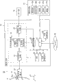
Fig. 1 is the skeleton diagram of structure that the diagnostic ultrasound equipment of this embodiment is shown.
Fig. 2 is the block diagram of function that the diagnostic ultrasound equipment of this embodiment is shown.
Fig. 3 is the figure that an example of scanning sequence is shown.
Fig. 4 is the figure that an example of the image that the image generative circuit generates through the control that is generated control part by image and carry out is shown.
Fig. 5 is the figure of an example that the image of the liver of depicting 2 points (tip portion-substantial portion of puncture needle) is shown.
Fig. 6 is the figure of an example of frequency spectrum that the RF signal of tip portion and substantial portion is shown.
Fig. 7 is the image generative circuit through the figure of an example that is generated the image that control that control part carries out generates by image.
Fig. 8 is the figure that an example of difference image is shown.
Fig. 9 is the figure that an example of superimposed images is shown.
Figure 10 is the figure that the localized area that comprises the guiding puncture line in the difference image is shown.
Figure 11 is the figure that illustrates based on the puncture line of this embodiment of first coordinate in the difference volume data and second coordinate.
Figure 12 A, Figure 12 B and Figure 12 C are the figure that the demonstration example of the guiding puncture line in the past when carrying out 3-D scanning is shown.
Figure 13 A, Figure 13 B and Figure 13 C are the routine figure of demonstration that the puncture line of this embodiment when carrying out 3-D scanning is shown.
Figure 14 is used to explain the fundametal compoment of reception signal and the figure of harmonic component.
Figure 15 is the figure that is used to explain based on the additive signal of the reception signal of two systems.
The specific embodiment
With reference to accompanying drawing, the embodiment of diagnostic ultrasound equipment of the present invention and ultrasonic diagnosis method is described.
Fig. 1 is the skeleton diagram of structure that the diagnostic ultrasound equipment of this embodiment is shown.
Fig. 1 illustrates the diagnostic ultrasound equipment 10 of this embodiment.This diagnostic ultrasound equipment 10 roughly is made up of puncture joint (adapter) 11, ultrasound probe 12, apparatus main body 13, display 14 and guidance panel 15.
The puncture joint 11 for example with the regulation fixed angle on ultrasound probe 12.On puncture joint 11, puncture needle (pin) 11a that thrusts to the zone of intravital puncture object (tumor) to from the surface of subject (patient) P is installed.
As ultrasound probe 12, for example, can enumerate mechanical type three-dimensional probe and 2D probe (matrix array probe) etc.The mechanical type three-dimensional probe is the probe that the piezoelectric vibrator crowd that only on X-direction (azimuth (azimuth) direction), is arranged in a plurality of (for example 100 or 200) is mechanically instigated, or can make and be arranged in a plurality of on the X-direction and on Y direction (elevation angle (elevation) direction), be arranged in the probe that the piezoelectric vibrator crowd of minority (for example three) mechanically instigates.In addition, the 2D probe is a probe of on X-direction and this two direction of Y direction, having arranged a plurality of piezoelectric vibrators.
At ultrasound probe 12 is under the situation of mechanical type three-dimensional probe; For with ultrasonic pulse pack and be formed on the Z-direction (depth direction) the suitable ultrasound beamformer that extends on X-direction, focus on electronically through on X-direction, being arranged in a plurality of piezoelectric vibrators.On the other hand; At ultrasound probe 12 is under the situation of mechanical type three-dimensional probe; For ultrasonic pulse is formed on the suitable ultrasound beamformer that extends on the Z-direction in pack on the Y direction, preferably the ultrasonic irradiation side at a piezoelectric vibrator possesses acoustic lens, perhaps piezoelectric vibrator is made the concave surface oscillator on Y direction.In addition; At ultrasound probe 12 is under the situation of mechanical type three-dimensional probe; For ultrasonic pulse is formed on the suitable ultrasound beamformer that extends on the Z-direction in pack on the Y direction, is possessing acoustic lens, or on Y direction, changing the driving number of minority piezoelectric vibrator according to the position of the Z-direction of focus in the ultrasonic irradiation side of minority piezoelectric vibrator on the Y direction.Using the mechanical type three-dimensional probe to come under the situation in scanning three-dimensional zone, Yi Bian the piezoelectric vibrator crowd is instigated, Yi Bian utilize the ultrasound beamformer that forms by ultrasonic pulse to scan a plurality of 2D sections (X-Z section).
At ultrasound probe 12 is under the situation of 2D probe; For with ultrasonic pulse pack and be formed on the suitable ultrasound beamformer that extends on the Z-direction on X-direction and Y direction, focus on electronically through on X-direction and Y direction, being arranged in a plurality of piezoelectric vibrators.Using 2D to pop one's head under the situation in scanning three-dimensional zone, Yi Bian the transmission face of ultrasonic pulse is squinted on Y direction, Yi Bian utilize the ultrasound beamformer that forms by ultrasonic pulse to scan a plurality of X-Z sections.
Apparatus main body 13 possesses transmitter/receiver circuit 21, signal processing circuit 22, image generative circuit 23, image storage 24, CPU (central processing unit; CPU) 25, internal storage device 26, IF (interface, interface) 27 and external memory 28.In addition; In this embodiment; Constitute integrated circuit with transmitter/receiver circuit 21, signal processing circuit 22 and image generative circuit 23 and be illustrated, but also can make their all or part of performance function with the modular software program of software mode through execution.
Transmitter/receiver circuit 21 is provided with not shown transtation mission circuit and receiving circuit.Transtation mission circuit has not shown pulse-generator circuit, transmission lag circuit and triggers generation circuit etc.According to the rules speed frequency f r Hz of pulse-generator circuit (cycle: 1/fr second) is used to form repeatedly and sends hyperacoustic speed pulse.In addition, the transmission lag circuit becomes the wave beam shape with the ultrasound wave pack to each passage, and, each speed pulse to be provided in order determining to send directivity and required time delay.Circuit trigger taking place according to the timing based on the speed pulse, applies driving pulse to the piezoelectric vibrator of ultrasound probe 12.
In addition, the transtation mission circuit of transmitter/receiver circuit 21 has following function: can be according to the indication of CPU25, and instantaneous change is sent frequency, sends driving voltage (acoustic pressure), is sent pulse rate, scanning area and flicker (flash) number of times etc.Particularly, for the change of acoustic pressure, the sending part of the linear amplification type through can switching its value moment or realize with the mechanism that electric mode is switched a plurality of power supply units.
The receiving circuit of transmitter/receiver circuit 21 has not shown amplifier, receive delay circuit, A/D (analog to digital, analog digital) change-over circuit and add circuit etc.In amplifier, the echo-signal that is taken into via ultrasound probe 12 is amplified to each passage.The receive delay circuit to provide in order determining the echo-signal after being amplified by amplifier and to receive directivity and required time delay.The A/D change-over circuit will convert digital signal into from the echo-signal of receive delay circuit output.Add circuit carries out addition process to the echo-signal of numeral.The addition that carries out through add circuit; Reflecting component from the direction corresponding with the reception directivity of echo-signal is stressed, according to receiving directivity and sending directivity, forms ultrasound wave and sends the synthesized beam that receives; Generate RF (radio frequency, radio frequency) signal.
Doppler's treatment circuit 22b carries out frequency resolution according to the RF signal that from transmitter/receiver circuit 21, obtains to velocity information; Extraction is based on the blood flow of Doppler effect or tissue, contrast agent echo component, and obtains blood flow informations such as average speed, dispersion and energy to multiple spot.Doppler's treatment circuit 22b generates average speed image, distributed image generation, energy diagram picture as blood flow information and the doppler image that their are made up.
Image generative circuit 23 will be from the profile image of the scanning-line signal string of the ultrasonic scanning of signal processing circuit 22 output, and being transformed to TV etc. is the profile image of scanning-line signal string of the general video format of representative.Image generative circuit 23 is equipped with the memorizer (not shown) of preserving image, for example can access images recorded in inspection operator after the diagnosis (user).In addition, image generative circuit 23 is according to profile image organizator data.
CPU25 is the control device with following integrated circuit (LSI) structure, and this integrated circuit is in the encapsulation with a plurality of terminals, to have enclosed the electronic circuit that is made up of quasiconductor to form.CPU25 has the function of carrying out the program in the internal storage device 26 that is stored in.In addition, CPU25 has following function: will be stored in program in the external memory 28, transmit and receive the program that is installed to the external memory 28 through IF27 from network N and be loaded into internal storage device 26 and carry out.
IF27 is by constituting with the parallel adapter that is connected specification or specification connected in series coupling.IF27 is the interface relevant with LAN network N, external memory 28 and the guidance panels 15 etc. such as (local area network, LANs) of guidance panel 15, hospital's core.Can pass through IF27, transmit the image that generates by apparatus main body 13 to other devices via network N.
Fig. 2 is the block diagram of function that the diagnostic ultrasound equipment 10 of this embodiment is shown.
Through CPU25 performing a programme shown in Figure 1, diagnostic ultrasound equipment 10 generates control part 31, difference image generation portion 32 and superimposed images generation portion 33 performance functions as image.In addition, difference image generation portion 32 is not a structural element essential in the diagnostic ultrasound equipment 10.In addition, in this embodiment, be made as each one 31 to 33 and bring into play function with the modular software program of software mode and be illustrated, but also can constitute they all or part of through hardware such as integrated circuits through carrying out.
Image generates control part 31 and has following function; Promptly control transmitter/receiver circuit 21, carry out successively to each grating (raster) (scanning line): based on from the substantial portion beyond the relative tip portion of reflected signal of the tip portion of puncture needle 11a more intense first send condition of acceptance ultrasound wave receive; Based on from the relative substantial portion of reflected signal of the tip portion of puncture needle 11a more weak second send condition of acceptance ultrasound wave receive; Send reception with ultrasound wave based on the 3rd transmission condition of acceptance different with the first transmission condition of acceptance and the second transmission condition of acceptance.Image generates control part 31 and for example makes and carry out sending to receive and send based on the ultrasound wave that second of high frequency sends condition of acceptance based on the ultrasound wave that first of low frequency sends condition of acceptance receiving.
Image generation control part 31 sends the transmission condition of condition of acceptance and at least one difference in the condition of acceptance through making formation, sets first thus and sends condition of acceptance, the second transmission condition of acceptance and the 3rd transmission condition of acceptance.In the transmission condition, for example can enumerate frequency (fundamental frequency), transmission impulse waveform, transmission impulse phase, send frequency, send train of pulse (burst) wave number, send driving element number (transmission opening) and transmission focusing (focus) (transmission lag) etc.As condition of acceptance, for example can enumerate receive frequency, received pulse string wave number, receive driving element number (reception opening) and collectiong focusing (receive delay) etc.
Fig. 3 is the figure that an example of scanning sequence (seq uence) is shown.
As shown in Figure 3; Ultrasound probe 12 about the first grating L1, carries out the ultrasound wave transmission reception of sending condition of acceptance based on first under the control of being undertaken by image generation control part 31; Next; Carry out sending reception, next, carry out the ultrasound wave transmission reception of sending condition of acceptance based on the 3rd based on the ultrasound wave of the second transmission condition of acceptance.Next; Ultrasound probe 12 about the second grating L2, carries out the ultrasound wave transmission reception of sending condition of acceptance based on first under the control of being undertaken by image generation control part 31; Next; Carry out sending reception, next, carry out the ultrasound wave transmission reception of sending condition of acceptance based on the 3rd based on the ultrasound wave of the second transmission condition of acceptance.Next; Ultrasound probe 12 about the 3rd grating L3, carries out the ultrasound wave transmission reception of sending condition of acceptance based on first under the control of being undertaken by image generation control part 31; Next; Carry out sending reception, next, carry out the ultrasound wave transmission reception of sending condition of acceptance based on the 3rd based on the ultrasound wave of the second transmission condition of acceptance.In addition; Ultrasound wave in each grating sends the order that receives and is not limited to situation shown in Figure 3; For example, also can be based on second send condition of acceptance ultrasound wave send receive, based on the 3rd send condition of acceptance ultrasound wave send receive and based on first send condition of acceptance ultrasound wave send and receive such order.
In addition; Image shown in Figure 2 generates control part 31 and has following function: control signal treatment circuit 22 and image generative circuit 23 generate based on through first send condition of acceptance the reception signal that obtains of scanning first image (first profile image, first volume data), based on through second send condition of acceptance the reception signal that obtains of scanning second image (second profile image, second volume data) and based on through the 3rd send condition of acceptance the 3rd image (the 3rd profile image, the 3rd volume data) of the reception signal that obtains of scanning, and be stored in the image storage 24.
In addition, it can be identical with the transmission condition enactment that the first transmission condition of acceptance, the second transmission condition of acceptance and the 3rd send condition of acceptance also that image generates control part 31, on the other hand condition of acceptance is set at different respectively.In this case, obtain and three three kinds of suitable images of transmission condition of acceptance through a ultrasound wave transmission.Therefore; Compare with the transmission condition condition of different that makes the first transmission condition of acceptance, second send condition of acceptance and the 3rd transmission condition of acceptance; Finish with 1/3 transmitting time, so have the advantage that to carry out difference processing or overlapping processing with common frame rate (in the situation lower body speed of volume data).
In addition; Transmission condition the first transmission condition of acceptance, second being sent condition of acceptance and the 3rd transmission condition of acceptance is made as identical; Make on the other hand under the condition of acceptance condition of different; Image generates control part 31 and sends condition of acceptance with first and be set at the condition that is used for the low-frequency band of echo-signal is carried out imageization, sends the condition that condition of acceptance and the 3rd sends imageization in the high frequency band that condition of acceptance is set at the comparison arrowband in echo-signal with second.In addition; Transmission condition the first transmission condition of acceptance, second being sent condition of acceptance and the 3rd transmission condition of acceptance is made as identical; Make on the other hand under the condition of acceptance condition of different; Image generates control part 31 will be than the wave beam sound field of broad, be set at first than the reception opening of the ultrasound probe 12 of broad sends condition of acceptance, the reception opening of narrow wave beam sound field, narrow ultrasound probe 12 is set at second sends condition of acceptance and the 3rd and send condition of acceptance.
Fig. 4 is the figure that an example of the image that image generative circuit 23 generates through the control that is generated control part 31 by image and carry out is shown.The left side of Fig. 4 is illustrated in the 3rd image that generates down to the state that has thrust puncture needle 11a as the agar phantom (agar phantom) of subject P, and the right side of Fig. 4 is illustrated in to the agar phantom and has thrust first image that generates under the state of puncture needle 11a.
According to first image shown in the right side of Fig. 4, deep or light about the part of the phantom beyond the tip portion of puncture needle 11a do not have so big difference, with respect to this, has only the deep or light different greatly of tip portion.In first image shown in the right side of Fig. 4, to compare with the 3rd image shown in the left side of Fig. 4, the tip portion of puncture needle 11a can clearly distinguish with the phantom part.
Fig. 5 is the figure of an example that the image of the liver of depicting 2 points (tip portion-substantial portion of puncture needle 11a) is shown.Fig. 6 is the figure of an example of frequency spectrum that the RF signal of tip portion and substantial portion is shown.
As shown in Figure 6, and compare from the RF signal of the substantial portion beyond the tip portion of puncture needle 11a, few at RF signal medium-high frequency component from tip portion.This be because, in the tip portion of puncture needle 11a, the generation of harmonic component less, or in lower frequency side, be easy to pick up at the reflected signal of the tip portion scattering of puncture needle 11a in the intrafascicular generation expansion of ultrasound waves etc.Therefore, be under arrowband and the situation at band setting than higher frequency band with imageization, obtain the few image of signal from the tip portion of puncture needle 11a, send condition of acceptance or the 3rd transmission condition of acceptance so be suitable for second.On the other hand, when lower frequency band was carried out image, the tip portion that obtains puncture needle 11a can be sent condition of acceptance so be suitable for first by the image of clearly distinguishing.
Fig. 7 is an image generative circuit 23 through the figure of an example that is generated the image that control that control part 31 carries out generates by image.
The upper left side of Fig. 7 illustrates first image of the agar phantom of having thrust puncture needle 11a that generates based on the first transmission condition of acceptance, and the left downside of Fig. 7 illustrates based on the 3rd and sends the 3rd image of the agar phantom of having thrust puncture needle 11a of condition of acceptance generation.In addition, the upper right side of Fig. 7 illustrates first image as the liver of subject P that sends based on first that condition of acceptance generates, and the lower right side of Fig. 7 illustrates the 3rd image that sends the liver that condition of acceptance generates through the 3rd.
When first image of the shown agar phantom up and down in the left side of Fig. 7 and the 3rd image are compared; Under the situation of first image; As stated; The tip portion of puncture needle 11a can clearly be distinguished, and under the situation of the 3rd image, the tip portion of puncture needle 11a is also unclear on the other hand.In addition, when first image of the shown liver up and down on the right side of Fig. 7 and the 3rd image are compared,, but almost do not see difference because there are the little differences such as fineness of speckle in the difference of decomposition.
In addition; Difference image generation portion 32 shown in Figure 2 has following function: first image and second image to image storage 24 is stored through the control of being undertaken by image generation control part 31 are implemented difference processing, generate difference image (difference profile image, difference volume data).In addition; Difference image generation portion 32 has following function: first image and second image that image generative circuit 23 is generated through the control that is generated control part 31 by image and carry out; Implement gain calibration respectively so that the brightness of substantial portion becomes after the same degree, to implementing difference processing and generate difference image based on first correcting image (first proofreaies and correct volume data) of first image and based on second correcting image (second proofreaies and correct volume data) of second image.In addition, difference image generation portion 32 both can carry out difference processing based on first image and second image that are transformed to behind the common video format, also can carry out difference processing based on first image and second image as the RAW data.
Fig. 8 is the figure that an example of difference image is shown.
According to the difference image of the agar phantom shown in the upside of Fig. 8, with the difference image of the liver shown in the downside of Fig. 8; Though how much comprise noise, in the difference image of agar phantom, the tip portion of puncture needle 11a is drawn out of; In the difference image of liver, tissue is eliminated on the other hand.That is, under the situation of in organism, having thrust puncture needle 11a, can only extract puncture needle 11a out through difference image.
In addition; Superimposed images generation portion 33 shown in Figure 2 has following function: based on the 3rd image that the difference image that is generated by difference image generation portion 32 and image storage 24 are stored through the control that is generated control part 31 by image and carry out, carry out overlapping processing and generate superimposed images.In addition, superimposed images generation portion 33 has following function: based on first image and the 3rd image that image storage 24 is stored through the control that is generated control part 31 by image and carry out, carry out overlapping processing and generate superimposed images.In addition; When having carried out 3-D scanning through the control of being undertaken by image generation control part 31; The section arbitrarily that comprises in superimposed images generation portion 33 the 3rd volume data to conduct the 3rd image of storing through the control that is generated control part 31 by image and carry out as the difference volume data of difference image and image storage 24 that is generated by difference image generation portion 32 is carried out overlapping processing and is generated superimposed images.
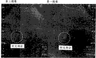
Fig. 9 is the figure that an example of superimposed images is shown.
As shown in Figure 9, when the difference image of using the tone different with the 3rd image that the tip portion by puncture needle 11a is constituted had carried out image, the operator is the position of the tip portion of visuognosis puncture needle 11a simply.In addition; In the past; Under the situation that the route of puncture needle 11a is kept watch on; To reduce frequency or expansion wave beam in order being easy to see the tip portion of puncture needle 11a, to have to use the transmission condition of acceptance of comparing deterioration with the image quality of observing common organism, be not suitable for the demonstration of substantial portion.But; Generating by superimposed images generation portion 33 and showing under the situation of superimposed images, can overlapping demonstration to the effective difference image of the demonstration of the tip portion of puncture needle 11a, effectively send the 3rd image that condition of acceptance obtains with the 3rd with demonstration to substantial portion.In addition, the operator operates the switch 15b of guidance panel 15 etc., thereby can also be in the regularly demonstration of switched differential image, superimposed images, first image (first correcting image), second image (second correcting image) and the 3rd image arbitrarily.
At this, in fact the organism as subject P is being thrust under the situation of puncture needle 11a, substantial portion can not be eliminated and remain on the difference image sometimes through the difference processing of being undertaken by difference image generation portion 32 fully.Therefore, superimposed images generation portion 33 also can be set in the localized area of the guiding puncture line g (illustrating among Figure 10) that comprises puncture needle 11a in the difference image, carries out overlapping processing based on the difference image and the 3rd image of area limiting.In addition, superimposed images generation portion 33 also can implement from difference image, to remove the Filtering Processing than higher frequency band (frequency band more than the threshold value).In this case, superimposed images generation portion 33 carries out overlapping processing based on difference image after the Filtering Processing and the 3rd image.In addition; Superimposed images generation portion 33 can not be the integral body to difference image yet; And only Filtering Processing is implemented in the localized area that comprises guiding puncture line g, based on the difference image of the area limiting after the Filtering Processing and the 3rd image of overall region, carry out overlapping processing.
In addition; Diagnostic ultrasound equipment 10 according to this embodiment; Be easy to carry out the separation on difference image from the substantial portion of the tip portion of puncture needle 11a; So can use difference image,, the tip portion of the puncture needle 11a of the reality (current) of thrusting detected according to the positional information of the puncture joint 11 that possesses puncture needle 11a.Therefore, generating under the situation of difference volume data through the control of being undertaken by image generation control part 31, superimposed images generation portion 33 can be according to the difference volume data, the coordinate of the tip portion of identification puncture needle 11a.For example; 33 pairs of difference volume datas of superimposed images generation portion are carried out pretreatment such as noise removal process or binary conversion treatment; The center of gravity of tip portion of obtaining detected puncture needle 11a is as the first coordinate [x1 of the tip portion of puncture needle 11a; Y1, z1] (being first coordinate [x1, y1] under the situation of difference profile image).In addition, because puncture joint 11 is known with the relative position relation of ultrasound probe 12, so superimposed images generation portion 33 can obtain second coordinate [x2, y2, z2] on the puncture joint 11 that the tip portion of puncture needle 11a must pass through.
As stated, superimposed images generation portion 33 is according to first coordinate in the difference volume data of being obtained and second coordinate, can discern the puncture line G (Figure 11 diagram) of the reality of this embodiment through first coordinate and second coordinate.In display 14, show puncture line G.
Figure 12 A, Figure 12 B and Figure 12 C are the figure that the demonstration example of the guiding puncture line g in the past when carrying out 3-D scanning is shown.
Figure 12 A illustrates the image of first section (A plane) on the guiding puncture line g of prior setting; Figure 12 B illustrate with the first section quadrature and the guiding puncture line g that sets in advance on the image of second section (cutting plane), Figure 12 C illustrates the image with vertical the 3rd section of second section (cutting plane).Each image is shown as moving image.Technological according in the past; First coordinate is set at the position of the puncture object of the tip portion of finally wanting to thrust puncture needle 11a; But in the tip portion that penetrates into intravital puncture needle 11a when guiding puncture line g breaks away from; The picture of puncture needle 11a disappears from each image, the position that the operator can't visuognosis puncture needle 11a.
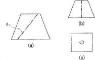
Figure 13 A, Figure 13 B and Figure 13 C are the routine figure of demonstration that the puncture line G of this embodiment when carrying out 3-D scanning is shown.
Figure 13 A, Figure 13 B and Figure 13 C illustrate the image with Figure 12 A, Figure 12 B and the identical section of Figure 12 C respectively.Because first coordinate according to the tip portion that goes out by superimposed images generation portion 33 actual detected; Calculate the puncture line G of puncture needle 11a aptly; So G is under the situation of three-dimensional system of coordinate at the puncture line, can show that shown in Figure 13 A and Figure 13 B the puncture line G with three-dimensional system of coordinate projects to the projection puncture line G ' of each section.In addition, shown in Figure 13 C,, be that the center shows circle with puncture line G and trisected intersection point for trisected image, can show the anticipation in-position of the tip portion of puncture needle 11a thus.Therefore, the operator can grasp the accurate position of puncture needle 11a, can carry out rapidly and puncture accurately.In addition, under the situation of the guiding puncture line g disengaging of prior setting, also can automatically change profile position, so that puncture line G is presented on each section at puncture needle 11a.
In addition, in image storage 24,, store second image of first image of a plurality of frames, a plurality of frames and the 3rd image of a plurality of frames respectively through generating the control that control part 31 carries out by image.Superimposed images generation portion 33 is created on the peaked brightness maximum image of the brightness that has kept the variation of time dependent ground in each pixel according to difference image, according to this brightness maximum image and the 3rd real-time image, generates superimposed images.Through generating successively and showing superimposed images based on brightness maximum image and real-time the 3rd image; When in body, having thrust puncture needle 11a; Show the track of the tip portion of puncture needle 11a, the visuognosis property raising of the puncture needle 11a in the supervision of puncture needle 11a with moving image.In the past, using the 3rd image to generate under the situation of the peaked image that has kept brightness, and, keeping the peaked image of brightness to generate so can't utilize because the pixel of substantial portion has also been kept the maximum of brightness.
In addition; The image of diagnostic ultrasound equipment 10 generates control part 31 and is not limited to following situation: send the reception signal that receives according to the ultrasound wave that obtains based on the scanning of sending condition of acceptance through first of low frequency and generate first image, send the reception signal that receives according to the ultrasound wave that obtains based on the scanning of sending condition of acceptance through second of high frequency and generate second image.For example, image generates control part 31 also can control signal treatment circuit 22 and image generative circuit 23, according to first-harmonic (fundamental) component that receives signal; Generate first image; And harmonic wave (harmonic) component according to receiving signal generates second image; Wherein, above-mentioned reception signal be based on through first send condition of acceptance the ultrasound wave that obtains of scanning send the reception signal that receives.
Figure 14 is used to explain the fundametal compoment of reception signal and the figure of harmonic component.
Figure 14 illustrates transverse axis is made as frequency (MHz), the longitudinal axis is made as the frequency spectrum of the reception signal of level of signal strength (dB).Shown in figure 14, receive signal and comprise fundametal compoment and harmonic component (2 order harmonic components, 3 order harmonic components).The fundametal compoment that receives signal comprises the information of the tip portion of more puncture needle 11a, and the harmonic component that receives signal on the other hand comprises the information of the tip portion of puncture needle 11a hardly.
In addition, generate in the control part 31, can also create (pulse invention) method by apply pulse at image shown in Figure 2.Image generates control part 31 also can control signal treatment circuit 22 and image generative circuit 23; According to through first send condition of acceptance the fundametal compoment of the reception signal that obtains of scanning; Generate first image; According to through first send condition of acceptance the reception signal that obtains of scanning, with comprise be included in first send the transmission impulse waveform in the condition of acceptance phase reversal the transmission impulse waveform pass through second send condition of acceptance the second harmonic component of additive signal of the reception signal that obtains of scanning, generate second image.
Figure 15 is the figure that is used to explain based on the additive signal of the reception signal of two systems.
Shown in figure 15, obtain to the left side epimere pass through first send condition of acceptance the reception signal that obtains of scanning, with the left side hypomere pass through second send condition of acceptance the reception signal that obtains of scanning carry out the additive signal after the addition process.
Claims (20)
1. diagnostic ultrasound equipment is characterized in that having:
Ultrasound probe sends ultrasound wave to two dimension or three-dimensional scanning area, receives based on above-mentioned hyperacoustic echo and as receiving signal;
Control unit; In order to control above-mentioned ultrasound probe; To the grating in the above-mentioned scanning area each, carry out successively based on first send condition of acceptance above-mentioned hyperacoustic transmission receive control, based on above-mentioned first send condition of acceptance different second send condition of acceptance above-mentioned hyperacoustic transmission receive control and based on above-mentioned first send condition of acceptance and above-mentioned second send condition of acceptance different the 3rd send condition of acceptance above-mentioned hyperacoustic transmission receive control;
The primary image generation unit, generate respectively based on utilize above-mentioned first send the above-mentioned reception signal that condition of acceptance obtains first image, based on utilize above-mentioned second send the above-mentioned reception signal that condition of acceptance obtains second image and based on utilize the above-mentioned the 3rd send the above-mentioned reception signal that condition of acceptance obtains the 3rd image;
The difference image generation unit is implemented difference processing and is generated difference image above-mentioned first image and above-mentioned second image; And
The superimposed images generation unit according to above-mentioned difference image and above-mentioned the 3rd image, is carried out overlapping processing and is generated superimposed images.
2. diagnostic ultrasound equipment according to claim 1 is characterized in that,
Also have the puncture needle that is used to thrust subject,
Above-mentioned ultrasound probe receives the above-mentioned echo of the above-mentioned scanning area of the tip portion that comprises above-mentioned seized intravital above-mentioned puncture needle,
Above-mentioned control unit is in order to control above-mentioned ultrasound probe, carry out based on from the substantial portion beyond the above-mentioned relatively tip portion of reflected signal of the tip portion of above-mentioned puncture needle more intense above-mentioned first send condition of acceptance and from the substantial portion beyond the above-mentioned relatively tip portion of reflected signal of the tip portion of above-mentioned puncture needle more weak above-mentioned second send condition of acceptance above-mentioned hyperacoustic transmission receive and control.
3. diagnostic ultrasound equipment according to claim 2 is characterized in that,
Also have correcting unit, this correcting unit carries out gain calibration to above-mentioned first image and above-mentioned second image, generates first correcting image and second correcting image respectively,
Above-mentioned difference image generation unit is implemented above-mentioned difference processing to above-mentioned first correcting image and above-mentioned second correcting image.
4. diagnostic ultrasound equipment according to claim 2 is characterized in that,
Above-mentioned superimposed images generation unit is in above-mentioned first image or above-mentioned difference image as the initial data of above-mentioned overlapping processing; Setting comprises the localized area of the guide line of above-mentioned puncture needle; According to above-mentioned the 3rd image of above-mentioned first image that has been set above-mentioned localized area and overall region, perhaps according to being set the above-mentioned difference image of above-mentioned localized area and above-mentioned the 3rd image of overall region, carry out above-mentioned overlapping processing.
5. diagnostic ultrasound equipment according to claim 2 is characterized in that,
Also have processing unit, this processing unit is implemented from as the Filtering Processing of removing the frequency band more than the threshold value above-mentioned first image of the initial data of above-mentioned overlapping processing or the above-mentioned difference image,
Above-mentioned first image and above-mentioned three image of above-mentioned superimposed images generation unit after, or, carry out above-mentioned overlapping processing according to above-mentioned difference image after the above-mentioned Filtering Processing and above-mentioned the 3rd image according to above-mentioned Filtering Processing.
6. diagnostic ultrasound equipment according to claim 5 is characterized in that,
Above-mentioned processing unit is only implemented above-mentioned Filtering Processing to the localized area of the guide line that comprises above-mentioned puncture needle; According to above-mentioned the 3rd image of above-mentioned first image of the area limiting after the above-mentioned Filtering Processing and overall region, or, carry out above-mentioned overlapping processing according to the above-mentioned difference image of the area limiting after the above-mentioned Filtering Processing and above-mentioned the 3rd image of overall region.
7. diagnostic ultrasound equipment according to claim 2 is characterized in that,
Above-mentioned primary image generation unit generates above-mentioned second image of above-mentioned first image of a plurality of frames, a plurality of frames and above-mentioned the 3rd image of a plurality of frames respectively.
8. diagnostic ultrasound equipment according to claim 7 is characterized in that,
Above-mentioned superimposed images generation unit is to each frame; According to above-mentioned first image or above-mentioned difference image as the initial data of above-mentioned overlapping processing; Be created on the peaked brightness maximum image of the brightness that has kept the variation of time dependent ground in each pixel; According to above-mentioned brightness maximum image and above-mentioned the 3rd image, carry out above-mentioned overlapping processing.
9. diagnostic ultrasound equipment according to claim 2 is characterized in that,
Above-mentioned primary image generation unit sends condition of acceptance based on above-mentioned first; According to the profile image crowd relevant with above-mentioned three-dimensional scanning area; Generation is as first volume data of above-mentioned first image, based on the above-mentioned second transmission condition of acceptance, according to the profile image crowd relevant with above-mentioned three-dimensional scanning area; Generation is as second volume data of above-mentioned second image; Based on above-mentioned the 3rd transmission condition of acceptance,, generate the 3rd volume data as above-mentioned the 3rd image according to the profile image crowd relevant with above-mentioned three-dimensional scanning area.
10. diagnostic ultrasound equipment according to claim 9 is characterized in that,
Also has extra cell; This extra cell is according to as above-mentioned first volume data of the initial data of above-mentioned overlapping processing or based on the difference volume data of above-mentioned first volume data and above-mentioned second volume data; Detect the position of above-mentioned tip portion; According to above-mentioned position and the positional information that possesses the puncture joint of above-mentioned puncture needle, calculate the puncture line of above-mentioned puncture needle, to the additional above-mentioned puncture line of above-mentioned superimposed images.
11. diagnostic ultrasound equipment according to claim 10 is characterized in that,
Above-mentioned superimposed images generation unit generates quadrature 3 profile images as above-mentioned superimposed images, to above-mentioned quadrature 3 profile images, the position of the above-mentioned tip portion of projection.
12. diagnostic ultrasound equipment according to claim 2 is characterized in that,
The transmission condition that above-mentioned control unit sends condition of acceptance and above-mentioned the 3rd transmission condition of acceptance with the above-mentioned first transmission condition of acceptance, above-mentioned second is made as identical, makes condition of acceptance different on the other hand.
13. diagnostic ultrasound equipment according to claim 12 is characterized in that,
Above-mentioned control unit sends condition of acceptance with above-mentioned first and is set at the condition that is used for the low-frequency band of above-mentioned reception signal is carried out imageization, sends the condition that condition of acceptance and the above-mentioned the 3rd sends imageization in the high frequency band that condition of acceptance is set at the arrowband in above-mentioned reception signal with above-mentioned second.
14. diagnostic ultrasound equipment according to claim 12 is characterized in that,
Above-mentioned control unit is set at above-mentioned first with the reception opening of wide wave beam sound field, wide above-mentioned ultrasound probe and sends condition of acceptance, the reception opening of narrow wave beam sound field, narrow above-mentioned ultrasound probe is set at above-mentioned second sends condition of acceptance and the above-mentioned the 3rd and send condition of acceptance.
15. a diagnostic ultrasound equipment is characterized in that having:
Ultrasound probe sends ultrasound wave to two dimension or three-dimensional scanning area, receives based on above-mentioned hyperacoustic echo as receiving signal;
Control unit; In order to control above-mentioned ultrasound probe; To the grating in the above-mentioned scanning area each, carry out successively controlling based on above-mentioned hyperacoustic transmission reception control of the first transmission condition of acceptance and based on above-mentioned hyperacoustic transmission reception of the 3rd transmission condition of acceptance different with the above-mentioned first transmission condition of acceptance;
The primary image generation unit, generate respectively based on utilize above-mentioned first send the above-mentioned reception signal that condition of acceptance obtains first image and based on utilize the above-mentioned the 3rd send the above-mentioned reception signal that condition of acceptance obtains the 3rd image;
The superimposed images generation unit according to above-mentioned first image and above-mentioned the 3rd image, is carried out overlapping processing and is generated superimposed images; And
Be used to thrust the puncture needle of subject,
Above-mentioned ultrasound probe receives the above-mentioned echo of the above-mentioned scanning area of the tip portion that comprises above-mentioned seized intravital above-mentioned puncture needle,
Above-mentioned control unit is in order to control above-mentioned ultrasound probe, carry out based on from the substantial portion beyond the above-mentioned relatively tip portion of reflected signal of the tip portion of above-mentioned puncture needle more intense above-mentioned first send condition of acceptance and from the substantial portion beyond the above-mentioned relatively tip portion of reflected signal of the tip portion of above-mentioned puncture needle more weak the above-mentioned the 3rd send condition of acceptance above-mentioned hyperacoustic transmission receive and control.
16. diagnostic ultrasound equipment according to claim 15 is characterized in that,
Above-mentioned control unit sends condition of acceptance with above-mentioned first and is set at the condition that is used for the low-frequency band of above-mentioned reception signal is carried out imageization, sends the condition that condition of acceptance and the above-mentioned the 3rd sends imageization in the high frequency band that condition of acceptance is set at the arrowband in above-mentioned reception signal with above-mentioned second.
17. a ultrasonic diagnosis image generating method is characterized in that having:
Controlled step; In order to control two dimension or three-dimensional scanning area to be sent ultrasound wave, received based on above-mentioned hyperacoustic echo as the ultrasound probe that receives signal; To the grating in the above-mentioned scanning area each, carry out successively based on first send condition of acceptance above-mentioned hyperacoustic transmission receive control, based on above-mentioned first send condition of acceptance different second send condition of acceptance above-mentioned hyperacoustic transmission receive control and based on above-mentioned first send condition of acceptance and above-mentioned second send condition of acceptance different the 3rd send condition of acceptance above-mentioned hyperacoustic transmission receive control;
Primary image generates step, generate respectively based on utilize above-mentioned first send the above-mentioned reception signal that condition of acceptance obtains first image, based on utilize above-mentioned second send the above-mentioned reception signal that condition of acceptance obtains second image and based on utilize the above-mentioned the 3rd send the above-mentioned reception signal that condition of acceptance obtains the 3rd image;
Difference image generates step, and above-mentioned first image and above-mentioned second image are implemented difference processing and generated difference image; And
According to above-mentioned difference image and above-mentioned the 3rd image, carry out overlapping processing and generate the step of superimposed images.
18. ultrasonic diagnosis image generating method according to claim 17 is characterized in that,
In above-mentioned controlled step; Comprise in reception under the situation of above-mentioned echo of above-mentioned scanning area of tip portion of puncture needle; In order to control above-mentioned ultrasound probe, carry out based on from the substantial portion beyond the above-mentioned relatively tip portion of reflected signal of the tip portion of above-mentioned puncture needle more intense above-mentioned first send condition of acceptance, with from the substantial portion beyond the above-mentioned relatively tip portion of reflected signal of the tip portion of above-mentioned puncture needle more weak above-mentioned second send condition of acceptance above-mentioned hyperacoustic transmission receive and control.
19. a ultrasonic diagnosis image generating method is characterized in that having:
Controlled step; In order to control the two dimension or the three-dimensional scanning area of the tip portion that comprises puncture needle to be sent ultrasound wave, are received based on above-mentioned hyperacoustic echo as the ultrasound probe that receives signal, carry out successively based on from the substantial portion beyond the above-mentioned relatively tip portion of reflected signal of the tip portion of above-mentioned puncture needle more intense first send condition of acceptance above-mentioned hyperacoustic transmission receive control and based on above-mentioned first send condition of acceptance different the 3rd send condition of acceptance above-mentioned hyperacoustic transmission receive control;
Generation based on utilize above-mentioned first send the above-mentioned reception signal that condition of acceptance obtains first image and based on utilize the above-mentioned the 3rd send the 3rd image of the above-mentioned reception signal that condition of acceptance obtains step; And
According to above-mentioned first image and above-mentioned the 3rd image, carry out overlapping processing and generate the step of superimposed images.
20. ultrasonic diagnosis image generating method according to claim 19 is characterized in that,
In above-mentioned controlled step; Comprise in reception under the situation of above-mentioned echo of above-mentioned scanning area of tip portion of puncture needle; In order to control above-mentioned ultrasound probe, carry out based on from the substantial portion beyond the above-mentioned relatively tip portion of reflected signal of the tip portion of above-mentioned puncture needle more intense above-mentioned first send condition of acceptance, with from the substantial portion beyond the above-mentioned relatively tip portion of reflected signal of the tip portion of above-mentioned puncture needle more weak the above-mentioned the 3rd send condition of acceptance above-mentioned hyperacoustic transmission receive and control.
Applications Claiming Priority (2)
| Application Number | Priority Date | Filing Date | Title |
|---|---|---|---|
| JP2009-028034 | 2009-02-10 | ||
| JP2009028034A JP5438985B2 (en) | 2009-02-10 | 2009-02-10 | Ultrasonic diagnostic apparatus and control program for ultrasonic diagnostic apparatus |
Publications (2)
| Publication Number | Publication Date |
|---|---|
| CN101797167A CN101797167A (en) | 2010-08-11 |
| CN101797167B true CN101797167B (en) | 2012-11-14 |
Family
ID=42133512
Family Applications (1)
| Application Number | Title | Priority Date | Filing Date |
|---|---|---|---|
| CN2010101041104A Active CN101797167B (en) | 2009-02-10 | 2010-01-27 | Ultrasonic diagnostic apparatus and ultrasonic diagnostic method |
Country Status (4)
| Country | Link |
|---|---|
| US (1) | US9119558B2 (en) |
| EP (1) | EP2215969B1 (en) |
| JP (1) | JP5438985B2 (en) |
| CN (1) | CN101797167B (en) |
Families Citing this family (32)
| Publication number | Priority date | Publication date | Assignee | Title |
|---|---|---|---|---|
| US9184369B2 (en) | 2008-09-18 | 2015-11-10 | Fujifilm Sonosite, Inc. | Methods for manufacturing ultrasound transducers and other components |
| US8663110B2 (en) | 2009-11-17 | 2014-03-04 | Samsung Medison Co., Ltd. | Providing an optimal ultrasound image for interventional treatment in a medical system |
| JP5645628B2 (en) * | 2010-12-09 | 2014-12-24 | 富士フイルム株式会社 | Ultrasonic diagnostic equipment |
| EP2454996A1 (en) * | 2010-11-17 | 2012-05-23 | Samsung Medison Co., Ltd. | Providing an optimal ultrasound image for interventional treatment in a medical system |
| CN102525547A (en) * | 2010-12-27 | 2012-07-04 | 通用电气公司 | Method and device for enhancing needle visualization in ultrasonic imaging |
| JP5778429B2 (en) * | 2011-01-04 | 2015-09-16 | 株式会社東芝 | Ultrasonic diagnostic equipment |
| JP6000569B2 (en) * | 2011-04-01 | 2016-09-28 | 東芝メディカルシステムズ株式会社 | Ultrasonic diagnostic apparatus and control program |
| JP6109498B2 (en) * | 2011-07-05 | 2017-04-05 | 東芝メディカルシステムズ株式会社 | Ultrasonic diagnostic apparatus and ultrasonic diagnostic apparatus control program |
| JP2013081764A (en) * | 2011-09-27 | 2013-05-09 | Toshiba Corp | Ultrasonic diagnostic apparatus and ultrasonic scanning method |
| JP5719275B2 (en) * | 2011-10-25 | 2015-05-13 | オリンパスメディカルシステムズ株式会社 | Ultrasound endoscope system |
| KR101468418B1 (en) | 2012-01-13 | 2014-12-03 | 삼성메디슨 주식회사 | Method and apparatus for processing ultrasound images |
| JP5645856B2 (en) * | 2012-01-30 | 2014-12-24 | ジーイー・メディカル・システムズ・グローバル・テクノロジー・カンパニー・エルエルシー | Transmission / reception circuit, ultrasonic probe, and ultrasonic image display device |
| JP5929368B2 (en) * | 2012-03-16 | 2016-06-01 | コニカミノルタ株式会社 | Ultrasound diagnostic imaging equipment |
| JP5507018B1 (en) * | 2012-07-27 | 2014-05-28 | オリンパスメディカルシステムズ株式会社 | Ultrasonic observation apparatus, operation method of ultrasonic observation apparatus, and operation program of ultrasonic observation apparatus |
| JP6257997B2 (en) * | 2012-10-23 | 2018-01-10 | 東芝メディカルシステムズ株式会社 | Ultrasonic diagnostic apparatus and ultrasonic diagnostic apparatus control method |
| CN103845075B (en) * | 2012-11-30 | 2016-09-28 | 通用电气公司 | Vltrasonic device and ultrasonic imaging method |
| GB201304798D0 (en) | 2013-03-15 | 2013-05-01 | Univ Dundee | Medical apparatus visualisation |
| EP2967496B1 (en) * | 2013-03-15 | 2020-04-29 | Conavi Medical Inc. | Active localization and visualization of minimally invasive devices using ultrasound |
| JP6114663B2 (en) * | 2013-08-27 | 2017-04-12 | 富士フイルム株式会社 | Ultrasonic diagnostic apparatus and ultrasonic image generation method |
| JP6207956B2 (en) * | 2013-10-03 | 2017-10-04 | 東芝メディカルシステムズ株式会社 | Ultrasonic diagnostic equipment |
| JP6405712B2 (en) * | 2014-05-30 | 2018-10-17 | コニカミノルタ株式会社 | Ultrasonic diagnostic equipment |
| CN104162223B (en) * | 2014-08-27 | 2017-01-11 | 深圳开立生物医疗科技股份有限公司 | Puncture guide wire arranging method, device and system |
| US10070837B2 (en) * | 2014-10-10 | 2018-09-11 | Canon Kabushiki Kaisha | Medical imaging apparatus, program installable in medical imaging apparatus, and medical imaging method |
| KR102035991B1 (en) * | 2015-01-16 | 2019-10-25 | 지멘스 메디컬 솔루션즈 유에스에이, 인크. | Method and ultrasound system for generating image of target object |
| EP3338641B1 (en) * | 2015-08-20 | 2020-01-15 | Konica Minolta, Inc. | Ultrasonic diagnostic imaging apparatus |
| JP6172330B2 (en) * | 2016-05-06 | 2017-08-02 | コニカミノルタ株式会社 | Ultrasound diagnostic imaging equipment |
| CN106236140B (en) * | 2016-08-25 | 2019-11-08 | 成都优途科技有限公司 | A kind of ultrasonic imaging method, apparatus and system |
| KR20180066781A (en) * | 2016-12-09 | 2018-06-19 | 삼성전자주식회사 | Method and apparatus for displaying medical image |
| CN107126260B (en) * | 2017-07-18 | 2019-09-13 | 深圳开立生物医疗科技股份有限公司 | Method for ultrasonic imaging, system and supersonic imaging apparatus |
| JP6800109B2 (en) * | 2017-08-22 | 2020-12-16 | オリンパス株式会社 | Endoscopic ultrasound |
| TWI743411B (en) * | 2017-11-08 | 2021-10-21 | 美商富士膠片索諾聲公司 | Ultrasound system with high frequency detail |
| EP3973896A4 (en) * | 2020-02-04 | 2023-07-12 | Tianli Zhao | Puncture needle positioning system and method |
Citations (3)
| Publication number | Priority date | Publication date | Assignee | Title |
|---|---|---|---|---|
| US4835712A (en) * | 1986-04-14 | 1989-05-30 | Pixar | Methods and apparatus for imaging volume data with shading |
| EP1416443A1 (en) * | 2002-10-28 | 2004-05-06 | Kabushiki Kaisha Toshiba | Image processing apparatus and ultrasound diagnosis apparatus |
| CN1718164A (en) * | 2004-07-07 | 2006-01-11 | 株式会社东芝 | Ultrasonic diagnostic apparatus, image processing apparatus and image processing method |
Family Cites Families (10)
| Publication number | Priority date | Publication date | Assignee | Title |
|---|---|---|---|---|
| JP3251682B2 (en) | 1993-01-11 | 2002-01-28 | 株式会社東芝 | Ultrasound diagnostic equipment |
| US5761331A (en) * | 1995-06-05 | 1998-06-02 | Intellectual Property Group Of Pillsbury Madison & Sutro Llp | Method and apparatus for tomographic imaging and image reconstruction using recombinant transverse phase differentials |
| JP2001061841A (en) * | 1999-08-30 | 2001-03-13 | Toshiba Corp | Ultrasonograph, and method of producing ultrasonic image |
| JP2006150069A (en) * | 2004-10-20 | 2006-06-15 | Toshiba Corp | Ultrasonic diagnostic equipment, and control method therefor |
| EP1803402A4 (en) | 2004-10-20 | 2008-10-29 | Toshiba Kk | Ultrasonic diagnostic equipment and control method therefor |
| JP4590293B2 (en) * | 2005-04-11 | 2010-12-01 | 富士フイルム株式会社 | Ultrasonic observation equipment |
| JP4381344B2 (en) * | 2005-05-17 | 2009-12-09 | ジーイー・メディカル・システムズ・グローバル・テクノロジー・カンパニー・エルエルシー | Ultrasonic diagnostic equipment |
| EP1982654B1 (en) * | 2006-03-31 | 2018-10-03 | Toshiba Medical Systems Corporation | Ultrasound diagnostic device and control method for ultrasound diagnostic device |
| JP4891651B2 (en) * | 2006-05-11 | 2012-03-07 | 日立アロカメディカル株式会社 | Ultrasonic diagnostic equipment |
| JP2008012150A (en) * | 2006-07-07 | 2008-01-24 | Toshiba Corp | Ultrasonic diagnostic equipment and control program of ultrasonic diagnostic equipment |
-
2009
- 2009-02-10 JP JP2009028034A patent/JP5438985B2/en active Active
-
2010
- 2010-01-27 CN CN2010101041104A patent/CN101797167B/en active Active
- 2010-02-09 EP EP10001322.6A patent/EP2215969B1/en active Active
- 2010-02-12 US US12/705,074 patent/US9119558B2/en active Active
Patent Citations (3)
| Publication number | Priority date | Publication date | Assignee | Title |
|---|---|---|---|---|
| US4835712A (en) * | 1986-04-14 | 1989-05-30 | Pixar | Methods and apparatus for imaging volume data with shading |
| EP1416443A1 (en) * | 2002-10-28 | 2004-05-06 | Kabushiki Kaisha Toshiba | Image processing apparatus and ultrasound diagnosis apparatus |
| CN1718164A (en) * | 2004-07-07 | 2006-01-11 | 株式会社东芝 | Ultrasonic diagnostic apparatus, image processing apparatus and image processing method |
Also Published As
| Publication number | Publication date |
|---|---|
| EP2215969A1 (en) | 2010-08-11 |
| US20100204579A1 (en) | 2010-08-12 |
| JP5438985B2 (en) | 2014-03-12 |
| JP2010183935A (en) | 2010-08-26 |
| CN101797167A (en) | 2010-08-11 |
| EP2215969B1 (en) | 2016-12-21 |
| US9119558B2 (en) | 2015-09-01 |
Similar Documents
| Publication | Publication Date | Title |
|---|---|---|
| CN101797167B (en) | Ultrasonic diagnostic apparatus and ultrasonic diagnostic method | |
| CN103179907B (en) | Diagnostic ultrasound equipment and ultrasonic scanning method | |
| US9943288B2 (en) | Method and system for ultrasound data processing | |
| CN103118598B (en) | Ultrasound diagnosis device, ultrasound image display device, and ultrasound image display method | |
| CN103251429B (en) | Ultrasonic imaging apparatus | |
| EP1546759B1 (en) | Ultrasound-imaging system and method for a user-guided three-dimensional volume-scan sequence | |
| CN101721224B (en) | Ultrasonic diagnostic device and ultrasonic image processing apparatus | |
| JP5433240B2 (en) | Ultrasonic diagnostic apparatus and image display apparatus | |
| JP6615603B2 (en) | Medical image diagnostic apparatus and medical image diagnostic program | |
| CN101884553B (en) | Ultrasonic diagnostic apparatus, ultrasonic image processing apparatus and ultrasonic image processing method | |
| CN103889337A (en) | Ultrasonic diagnostic device and ultrasonic diagnostic device control method | |
| CN104981208A (en) | Ultrasonic diagnostic device and control program | |
| US20180206825A1 (en) | Method and system for ultrasound data processing | |
| CN103169500A (en) | Ultrasonic diagnostic apparatus, medical image diagnostic apparatus, and medical image processing method | |
| US4078435A (en) | Simultaneous display of compound and simple ultrasound scans | |
| CN111110277B (en) | Ultrasonic imaging method, ultrasonic apparatus, and storage medium | |
| CN102090901B (en) | Medical image display apparatus | |
| CN102365054B (en) | Ultrasonograph and urtrasonic processing device | |
| CN102626328B (en) | Diagnostic ultrasound equipment, Ultrasonographic device and adquisitiones | |
| JP2005342194A (en) | Ultrasonic diagnostic apparatus | |
| EP3838162A1 (en) | Systems and methods for assessing a placenta | |
| JP2001017428A (en) | Opacity setting method, method and device for forming three-dimensional image, and ultrasonic image pick-up device | |
| CN102125443B (en) | Ultrasonic wave diagnosis device and ultrasonic image processor | |
| JP4599208B2 (en) | Ultrasonic diagnostic equipment | |
| JP5139037B2 (en) | Ultrasonic diagnostic apparatus and image processing apparatus |
Legal Events
| Date | Code | Title | Description |
|---|---|---|---|
| C06 | Publication | ||
| PB01 | Publication | ||
| C10 | Entry into substantive examination | ||
| SE01 | Entry into force of request for substantive examination | ||
| C14 | Grant of patent or utility model | ||
| GR01 | Patent grant | ||
| C41 | Transfer of patent application or patent right or utility model | ||
| TR01 | Transfer of patent right |
Effective date of registration: 20160718 Address after: Japan Tochigi Patentee after: Toshiba Medical System Co., Ltd. Address before: Tokyo, Japan, Japan Patentee before: Toshiba Corp Patentee before: Toshiba Medical System Co., Ltd. |