EP2215969B1 - Ultrasonic diagnostic apparatus and ultrasonic diagnostic method - Google Patents
Ultrasonic diagnostic apparatus and ultrasonic diagnostic method Download PDFInfo
- Publication number
- EP2215969B1 EP2215969B1 EP10001322.6A EP10001322A EP2215969B1 EP 2215969 B1 EP2215969 B1 EP 2215969B1 EP 10001322 A EP10001322 A EP 10001322A EP 2215969 B1 EP2215969 B1 EP 2215969B1
- Authority
- EP
- European Patent Office
- Prior art keywords
- image
- condition
- transmitting
- needle
- under
- Prior art date
- Legal status (The legal status is an assumption and is not a legal conclusion. Google has not performed a legal analysis and makes no representation as to the accuracy of the status listed.)
- Active
Links
- 238000002405 diagnostic procedure Methods 0.000 title claims description 6
- 239000002131 composite material Substances 0.000 claims description 49
- 239000000523 sample Substances 0.000 claims description 37
- 238000001914 filtration Methods 0.000 claims description 8
- 238000003384 imaging method Methods 0.000 claims description 3
- 238000010586 diagram Methods 0.000 description 28
- 230000005540 biological transmission Effects 0.000 description 22
- 230000006870 function Effects 0.000 description 18
- 229920001817 Agar Polymers 0.000 description 7
- 239000008272 agar Substances 0.000 description 7
- 210000004185 liver Anatomy 0.000 description 7
- 238000000034 method Methods 0.000 description 7
- 210000001519 tissue Anatomy 0.000 description 6
- 230000017531 blood circulation Effects 0.000 description 5
- 238000006243 chemical reaction Methods 0.000 description 5
- 238000012544 monitoring process Methods 0.000 description 5
- 238000001514 detection method Methods 0.000 description 4
- 238000003745 diagnosis Methods 0.000 description 4
- 206010028980 Neoplasm Diseases 0.000 description 3
- 238000010317 ablation therapy Methods 0.000 description 3
- 238000001574 biopsy Methods 0.000 description 3
- 238000002592 echocardiography Methods 0.000 description 3
- 238000001228 spectrum Methods 0.000 description 3
- 238000002560 therapeutic procedure Methods 0.000 description 3
- 108010076504 Protein Sorting Signals Proteins 0.000 description 2
- 230000000747 cardiac effect Effects 0.000 description 2
- 239000002872 contrast media Substances 0.000 description 2
- 239000006185 dispersion Substances 0.000 description 2
- 230000000694 effects Effects 0.000 description 2
- 238000007674 radiofrequency ablation Methods 0.000 description 2
- 230000003187 abdominal effect Effects 0.000 description 1
- 230000003321 amplification Effects 0.000 description 1
- 238000004458 analytical method Methods 0.000 description 1
- 230000008901 benefit Effects 0.000 description 1
- 201000011510 cancer Diseases 0.000 description 1
- 230000008859 change Effects 0.000 description 1
- 230000001419 dependent effect Effects 0.000 description 1
- 230000003631 expected effect Effects 0.000 description 1
- 239000000284 extract Substances 0.000 description 1
- 230000005484 gravity Effects 0.000 description 1
- 206010073071 hepatocellular carcinoma Diseases 0.000 description 1
- 230000010354 integration Effects 0.000 description 1
- 230000003902 lesion Effects 0.000 description 1
- 239000004973 liquid crystal related substance Substances 0.000 description 1
- 208000014018 liver neoplasm Diseases 0.000 description 1
- 239000000696 magnetic material Substances 0.000 description 1
- 239000011159 matrix material Substances 0.000 description 1
- 230000007246 mechanism Effects 0.000 description 1
- 239000002184 metal Substances 0.000 description 1
- 239000000203 mixture Substances 0.000 description 1
- 238000003199 nucleic acid amplification method Methods 0.000 description 1
- 238000007781 pre-processing Methods 0.000 description 1
- 230000008569 process Effects 0.000 description 1
- 230000002787 reinforcement Effects 0.000 description 1
- 239000004065 semiconductor Substances 0.000 description 1
- 238000000926 separation method Methods 0.000 description 1
- 210000004872 soft tissue Anatomy 0.000 description 1
- 230000007480 spreading Effects 0.000 description 1
- 230000001225 therapeutic effect Effects 0.000 description 1
Images


Classifications
-
- A—HUMAN NECESSITIES
- A61—MEDICAL OR VETERINARY SCIENCE; HYGIENE
- A61B—DIAGNOSIS; SURGERY; IDENTIFICATION
- A61B8/00—Diagnosis using ultrasonic, sonic or infrasonic waves
- A61B8/08—Detecting organic movements or changes, e.g. tumours, cysts, swellings
- A61B8/0833—Detecting organic movements or changes, e.g. tumours, cysts, swellings involving detecting or locating foreign bodies or organic structures
-
- A—HUMAN NECESSITIES
- A61—MEDICAL OR VETERINARY SCIENCE; HYGIENE
- A61B—DIAGNOSIS; SURGERY; IDENTIFICATION
- A61B17/00—Surgical instruments, devices or methods, e.g. tourniquets
- A61B17/34—Trocars; Puncturing needles
- A61B17/3403—Needle locating or guiding means
-
- A—HUMAN NECESSITIES
- A61—MEDICAL OR VETERINARY SCIENCE; HYGIENE
- A61B—DIAGNOSIS; SURGERY; IDENTIFICATION
- A61B8/00—Diagnosis using ultrasonic, sonic or infrasonic waves
- A61B8/08—Detecting organic movements or changes, e.g. tumours, cysts, swellings
- A61B8/0833—Detecting organic movements or changes, e.g. tumours, cysts, swellings involving detecting or locating foreign bodies or organic structures
- A61B8/0841—Detecting organic movements or changes, e.g. tumours, cysts, swellings involving detecting or locating foreign bodies or organic structures for locating instruments
-
- G—PHYSICS
- G01—MEASURING; TESTING
- G01S—RADIO DIRECTION-FINDING; RADIO NAVIGATION; DETERMINING DISTANCE OR VELOCITY BY USE OF RADIO WAVES; LOCATING OR PRESENCE-DETECTING BY USE OF THE REFLECTION OR RERADIATION OF RADIO WAVES; ANALOGOUS ARRANGEMENTS USING OTHER WAVES
- G01S7/00—Details of systems according to groups G01S13/00, G01S15/00, G01S17/00
- G01S7/52—Details of systems according to groups G01S13/00, G01S15/00, G01S17/00 of systems according to group G01S15/00
- G01S7/52017—Details of systems according to groups G01S13/00, G01S15/00, G01S17/00 of systems according to group G01S15/00 particularly adapted to short-range imaging
- G01S7/52053—Display arrangements
- G01S7/52057—Cathode ray tube displays
- G01S7/52074—Composite displays, e.g. split-screen displays; Combination of multiple images or of images and alphanumeric tabular information
-
- G—PHYSICS
- G01—MEASURING; TESTING
- G01S—RADIO DIRECTION-FINDING; RADIO NAVIGATION; DETERMINING DISTANCE OR VELOCITY BY USE OF RADIO WAVES; LOCATING OR PRESENCE-DETECTING BY USE OF THE REFLECTION OR RERADIATION OF RADIO WAVES; ANALOGOUS ARRANGEMENTS USING OTHER WAVES
- G01S7/00—Details of systems according to groups G01S13/00, G01S15/00, G01S17/00
- G01S7/52—Details of systems according to groups G01S13/00, G01S15/00, G01S17/00 of systems according to group G01S15/00
- G01S7/52017—Details of systems according to groups G01S13/00, G01S15/00, G01S17/00 of systems according to group G01S15/00 particularly adapted to short-range imaging
- G01S7/52085—Details related to the ultrasound signal acquisition, e.g. scan sequences
-
- A—HUMAN NECESSITIES
- A61—MEDICAL OR VETERINARY SCIENCE; HYGIENE
- A61B—DIAGNOSIS; SURGERY; IDENTIFICATION
- A61B17/00—Surgical instruments, devices or methods, e.g. tourniquets
- A61B17/34—Trocars; Puncturing needles
- A61B17/3403—Needle locating or guiding means
- A61B2017/3413—Needle locating or guiding means guided by ultrasound
-
- G—PHYSICS
- G01—MEASURING; TESTING
- G01S—RADIO DIRECTION-FINDING; RADIO NAVIGATION; DETERMINING DISTANCE OR VELOCITY BY USE OF RADIO WAVES; LOCATING OR PRESENCE-DETECTING BY USE OF THE REFLECTION OR RERADIATION OF RADIO WAVES; ANALOGOUS ARRANGEMENTS USING OTHER WAVES
- G01S15/00—Systems using the reflection or reradiation of acoustic waves, e.g. sonar systems
- G01S15/88—Sonar systems specially adapted for specific applications
- G01S15/89—Sonar systems specially adapted for specific applications for mapping or imaging
- G01S15/8906—Short-range imaging systems; Acoustic microscope systems using pulse-echo techniques
- G01S15/895—Short-range imaging systems; Acoustic microscope systems using pulse-echo techniques characterised by the transmitted frequency spectrum
- G01S15/8952—Short-range imaging systems; Acoustic microscope systems using pulse-echo techniques characterised by the transmitted frequency spectrum using discrete, multiple frequencies
-
- G—PHYSICS
- G01—MEASURING; TESTING
- G01S—RADIO DIRECTION-FINDING; RADIO NAVIGATION; DETERMINING DISTANCE OR VELOCITY BY USE OF RADIO WAVES; LOCATING OR PRESENCE-DETECTING BY USE OF THE REFLECTION OR RERADIATION OF RADIO WAVES; ANALOGOUS ARRANGEMENTS USING OTHER WAVES
- G01S7/00—Details of systems according to groups G01S13/00, G01S15/00, G01S17/00
- G01S7/52—Details of systems according to groups G01S13/00, G01S15/00, G01S17/00 of systems according to group G01S15/00
- G01S7/52017—Details of systems according to groups G01S13/00, G01S15/00, G01S17/00 of systems according to group G01S15/00 particularly adapted to short-range imaging
- G01S7/52023—Details of receivers
- G01S7/52036—Details of receivers using analysis of echo signal for target characterisation
- G01S7/52038—Details of receivers using analysis of echo signal for target characterisation involving non-linear properties of the propagation medium or of the reflective target
Definitions
- the present invention relates to a technique capable of a two-dimensional (2D) scanning and a real time three-dimensional (3D) scanning, and more particularly to an ultrasonic diagnostic apparatus and an ultrasonic diagnostic method that emphatically displays a needle-tip portion of a puncture needle so that an operator can easily visually recognize a position of the needle-tip portion.
- An ultrasonic diagnostic apparatus is a medical diagnostic apparatus that noninvasively obtains tomograms of a soft tissue in a living body from a body surface using an ultrasonic pulse-echo method.
- the ultrasonic diagnostic apparatus has features that the apparatus is compact and inexpensive, has high safety with no exposure to X-rays, is capable of blood flow imaging, or the like as compared with other medical diagnostic apparatuses, and has been widely used in cardiac, abdominal, urology, obstetrics and gynecology departments, or the like.
- the ultrasonic diagnostic apparatus is used not only for image diagnosis but also, for example, for radiofrequency ablation (RFA) as a local therapy of hepatocellular cancer or a biopsy for hepatocellular tissue examination.
- RFID radiofrequency ablation
- Such a therapy and an examination require precise puncture into a region of interest such as a tumor using a puncture needle.
- an ultrasonic diagnostic apparatus that can monitor the region of interest and the puncture needle in real time is used.
- the ultrasonic diagnostic apparatus sometimes uses real time three-dimensional ultrasonic images for display because of faster computers.
- an ultrasonic diagnostic apparatus capable of a real time volume scanning has also appeared.
- This apparatus can obtain needle position information in a slice direction of an ultrasonic probe, which has been hard to obtain, and is expected to increase accuracy of a biopsy or an ablation therapy.
- the ultrasonic diagnostic apparatus in the related art sometimes has poor visibility because the visualized needle-tip portion of the puncture needle is buried in a background image, or the like, and places a burden on an operator. Also, because of uncertainty about the precise position of the needle-tip portion of the puncture needle, sufficient therapeutic effects may not be obtained such that tissue in a different position from the position of planned tissue is removed or an ablation therapy is performed in a different position.
- US 2006/0241451 A1 relates to enhancements in the reliability and accuracy of, for example puncture under ultrasonic guide, and more particularly to an ultrasonic diagnostic equipment which is used for the betterment of the visibility of a puncture needle, and a method of controlling the equipment.
- the present invention has been achieved in view of such circumstances, and has an object to provide an ultrasonic diagnostic apparatus and an ultrasonic diagnostic method that allows an operator to easily visually recognize the position of a needle-tip portion of a puncture needle in monitoring the puncture needle.
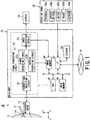
- Fig. 1 is a schematic diagram showing a configuration of ultrasonic diagnostic apparatus of the present embodiment.
- Fig. 1 shows an ultrasonic diagnostic apparatus 10 of the present embodiment.
- the ultrasonic diagnostic apparatus 10 mainly has a puncture adaptor 11, an ultrasonic probe 12, a main body 13, a display 14, and an operation panel 15.
- the puncture adaptor 11 is, for example, secured to the ultrasonic probe 12 at a predetermined angle.
- a puncture needle 11a to be inserted into a region from a body surface of an object (patient) P to a puncture target (tumor) in the body is mounted.
- the ultrasonic probe 12 has a plurality of piezoelectric transducers that transmit ultrasonic pulses to a two-dimensional or a three-dimensional scanning region including the puncture target of the patient P based on drive pulses from the main body 13, and receive echoes corresponding to the transmitted ultrasonic pulses, and convert the echoes into electric signals.
- the piezoelectric transducers in the ultrasonic probe 12 transmit the ultrasonic pulses to the scanning region, ultrasonic beams formed by the ultrasonic pulses are successively reflected by a discontinuous surface of acoustic impedance of body tissue.
- the reflected echoes are received by the piezoelectric transducers.
- the received echo is converted into an echo signal by the piezoelectric transducers.
- An amplitude of the echo signal depends on a difference in acoustic impedance on the reflecting discontinuous surface.
- an echo corresponding to the transmitted ultrasonic pulse depends on a speed component in an ultrasonic transmitting direction of a mobile object by the Doppler effect, and undergoes frequency deviation.
- the ultrasonic probe 12 includes, for example, a mechanical three-dimensional probe and a two-dimensional probe (matrix array probe).
- the mechanical three-dimensional probe is a probe that can mechanically sweep many (for example, 100 to 200) piezoelectric transducers arranged only in an X-axis direction (azimuth direction), or a probe that can mechanically sweep many piezoelectric transducers arranged in the X-axis direction and a few (for example, 3) piezoelectric transducers arranged in a Y-axis direction (elevation direction).
- the two-dimensional probe is a probe having many piezoelectric transducers arranged in both the X-axis direction and the Y-axis direction.
- the many piezoelectric transducers arranged in the X-axis direction obtain electronic focus so as to cause the ultrasonic pulse to converge in the X-axis direction to form an appropriate ultrasonic beam extending in a Z-axis direction (depth direction).
- the ultrasonic probe 12 is the mechanical three-dimensional probe, it is preferable that an acoustic lens is provided on an ultrasonic irradiation side of one piezoelectric transducer in the Y-axis direction or the piezoelectric transducer is formed as a concave type so as to cause the ultrasonic pulse to converge in the Y-axis direction to form an appropriate ultrasonic beam extending in the Z-axis direction.
- an acoustic lens is provided on an ultrasonic irradiation side of a few piezoelectric transducers in the Y-axis direction, or the number of driven piezoelectric transducers among the few piezoelectric transducers is changed in the Y-axis direction depending on the position of a focus in the Z-axis direction so as to cause the ultrasonic pulse to converge in the Y-axis direction to form an appropriate ultrasonic beam extending in the Z-axis direction.
- a plurality of two-dimensional cross-sections are scanned by the ultrasonic beam formed by the ultrasonic pulse while the piezoelectric transducers is swept.
- the many piezoelectric transducers arranged in the X-axis direction and the Y-axis direction obtain electronic focus so as to cause the ultrasonic pulse to converge in the X-axis direction and the Y-axis direction to form an appropriate ultrasonic beam extending in the Z-axis direction.
- a plurality of X-Z cross-sections are scanned by the ultrasonic beam formed by the ultrasonic pulse while a transmission surface of the ultrasonic pulse is electronically shifted in the Y-axis direction.
- the main body 13 has a transmitting/receiving circuit 21, a signal processing circuit 22, an image generating circuit 23, an image memory 24, a central processing unit (CPU) 25, a main memory 26, an interface (IF) 27, and a storage 28.
- the transmitting/receiving circuit 21, the signal processing circuit 22, and the image generating circuit 23 are configured as integrated circuits for description, but all or part thereof may function by execution of a modularized software program.
- the transmitting/receiving circuit 21 has a transmitting circuit and a receiving circuit, not shown.
- the transmitting circuit has a pulser circuit, a transmission delay circuit, a trigger generating circuit, or the like, not shown.
- the pulser circuit repeatedly generates rate pulses for forming transmitting ultrasonic at a predetermined rate frequency fr [Hz] (cycle: 1/fr [sec]).
- the transmission delay circuit provides each rate pulse with a delay time required for focusing the ultrasonic into the beam for each channel and determining a transmission directivity.
- the trigger generating circuit applies a drive pulse to the piezoelectric transducer in the ultrasonic probe 12 at timing based on the rate pulse.
- the transmitting circuit in the transmitting/receiving circuit 21 has a function of instantaneously changing a transmission frequency, a transmission drive voltage (sound pressure), a transmission pulse rate, a scanning region, and the number of flashes according to instructions from the CPU 25.
- the sound pressure is changed by a transmitting portion of linear amplifier type that can instantaneously change the value of the sound pressure or a mechanism that electrically switches a plurality of power supply portions.
- the receiving circuit in the transmitting/receiving circuit 21 has an amplifier, a receiving delay circuit, an analog to digital (A/D) conversion circuit, an addition circuit, or the like, not shown.
- the amplifier amplifies an echo signal captured via the ultrasonic probe 12 for each channel.
- the receiving delay circuit provides the echo signal amplified by the amplifier with a delay time required for determining a receiving directivity.
- the A/D conversion circuit converts the echo signal output from the receiving delay circuit into a digital signal.
- the addition circuit performs an addition processing of the digital echo signal.
- the addition by the addition circuit enhances a reflection component from a direction according to the receiving directivity of the echo signal, the receiving directivity and the transmitting directivity form an overall beam for ultrasonic transmitting and receiving, and a radio frequency (RF) signal is generated.
- RF radio frequency
- the signal processing circuit 22 has a B-mode processing circuit 22a and a Doppler processing circuit 22b.
- the B-mode processing circuit 22a performs logaritmetic amplification and envelope detection or the like of the RF signal obtained from the transmitting/receiving circuit 21, and generates a B-mode image with signal intensity expressed by brightness.
- a visualized frequency band can be changed by changing a detection frequency. Detection processes with two detection frequencies may be performed for one receiving data in parallel.
- the Doppler processing circuit 22b performs frequency analysis of speed information from the RF signal obtained from the transmitting/receiving circuit 21, extracts blood flow, tissue, or a contrast medium echo component by the Doppler effect, and calculates blood flow information such as an average speed, dispersion and power for many points.
- the Doppler processing circuit 22b generates an average speed image, a dispersion image, and a power image as blood flow information and a Doppler image as a combination thereof.
- the image generating circuit 23 converts a cross-sectional image of a scan line signal sequence of ultrasonic scanning, which is output from the signal processing circuit 22, into a cross-sectional image of a scan line signal sequence in a general video format typified in, for example, televisions.
- the image generating circuit 23 includes a memory (not shown) that stores an image. For example, after a diagnosis, an operator (or a user) can call up an image recorded during an examination. Further, the image generating circuit 23 forms volume data on the basis of the cross-sectional images.
- the image memory 24 is a storage device that stores images output from the signal processing circuit 22 and the image generating circuit 23. In the image memory 24, images obtained under different transmitting/receiving conditions are stored in parallel.
- the image memory 24 stores a cross-sectional image of data format before conversion that is referred to as so-called RAW data output from the signal processing circuit 22, a cross-sectional image of data format after video format conversion output from the image generating circuit 23, and volume data based on the cross-sectional image of data format after the video format conversion output from the image generating circuit 23.
- the CPU 25 is a control device having a configuration of an integrated circuit (LSI) in which an electronic circuit configured by a semiconductor is sealed in a package having a plurality of terminals.
- the CPU 25 has a function of executing a program stored in the main memory 26.
- the CPU 25 has a function of loading a program stored in the storage 28 and a program transferred from a network N, received by the IF 27 and installed in the storage 28, into the main memory 26, and performing the programs.
- the main memory 26 is a storage device having a configuration that also serves as a read only memory (ROM), a random access memory (RAM), or the like.
- the main memory 26 has a function of storing initial program loading (IPL: large scale integration), basic input/output system (BIOS) and data, or temporarily storing a work memory or data of the CPU 25.
- IPL initial program loading
- BIOS basic input/output system
- the IF 27 is configured by a connector of parallel connection specifications or serial connection specifications.
- the IF 27 is an interface relating to the operation panel 15, the network N such as a basic local area network (LAN) of a hospital, the storage 28, or the like.
- the image generated by the main body 13 can be transferred to other systems via the network N by the IF 27.
- the storage 28 is a storage device having a configuration in which a metal disk with a magnetic material applied or evaporated is irremovably installed in a reading device (not shown).
- the storage 28 has a function of storing a program (including an application program and also an OS (operating system) or the like) installed in the main body 13.
- the OS may be provided with a graphical user interface (GUI) that can use many graphics in displaying information for the operator, and can perform a basic operation with the operation panel 15.
- GUI graphical user interface
- the main memory 26 or the storage 28 store a control program such as an ultrasonic diagnosis program, diagnosis information (patient identification (ID), doctor's observation, or the like), a diagnosis protocol, a transmitting/receiving condition, and other groups of data. Further, the data stored in the main memory 26 or the storage 28 can be transferred to the network N via the IF 27.
- a control program such as an ultrasonic diagnosis program, diagnosis information (patient identification (ID), doctor's observation, or the like), a diagnosis protocol, a transmitting/receiving condition, and other groups of data. Further, the data stored in the main memory 26 or the storage 28 can be transferred to the network N via the IF 27.
- the display 14 may be a liquid crystal display or a cathode ray tube (CRT).
- the display 14 has a function of displaying two-dimensional data or three-dimensional data together with character information or scales of various parameters based on a video signal from the image generating circuit 23.
- the operation panel 15 may be a trackball 15a, various switches 15b, a button 15c, a mouse 15d, a keyboard 15e, or the like.
- the operation panel 15 is connected to the main body 13, and has a function of inputting various instructions from the operator, for example, a setting instruction of a region of interest (ROI), a setting instruction of an image quality condition to the main body 13.
- the operator can input a transmission frequency of the ultrasonic pulse transmitted from the ultrasonic probe 12, a transmission drive voltage (sound pressure), a transmission pulse rate, a scanning region, puncture mode start and contrast medium flush instructions, a receiving condition, or the like to the main body 13 via the operation panel 15.
- Fig. 2 is a block diagram showing a function of the ultrasonic diagnostic apparatus 10 of the present embodiment.
- the CPU 25 shown in Fig. 1 executes a program, and thus the ultrasonic diagnostic apparatus 10 functions as an image generation control unit 31, a differential image generating unit 32, and a composite image generating unit 33.
- the differential image generating unit 32 is not a component essential to the ultrasonic diagnostic apparatus 10.
- the units 31 to 33 function by execution of a modularized software program for description, but all or part thereof may be configured by hardware such as an integrated circuit.
- the image generation control unit 31 has a function of controlling the transmitting/receiving circuit 21 so as to sequentially perform, for each raster (scanning line), ultrasonic transmitting and receiving under a first transmitting/receiving condition in which a reflection signal from the needle-tip portion of the puncture needle 11a is relatively stronger than a substantial portion other than the needle-tip portion, ultrasonic transmitting and receiving under a second transmitting/receiving condition in which the reflection signal from the needle-tip portion of the puncture needle 11a is relatively weaker than the substantial portion, and ultrasonic transmitting and receiving under a third transmitting/receiving condition different from the first transmitting/receiving condition and the second transmitting/receiving condition.
- the image generation control unit 31 causes the transmitting/receiving circuit 21 to perform the ultrasonic transmitting and receiving under the first transmitting/receiving condition at a low frequency, and the ultrasonic transmitting and receiving under the second transmitting/receiving condition at a high frequency.
- the image generation control unit 31 changes at least one of a transmitting condition and a receiving condition included in the transmitting/receiving condition to set the first transmitting/receiving condition, the second transmitting/receiving condition, and the third transmitting/receiving condition.
- the transmitting condition includes, for example, a frequency (fundamental frequency), a transmission pulse waveform, a transmission pulse phase, a transmission frequency, the number of transmission burst waves, the number of transmission drive elements (transmission opening), a transmission focus (transmission delay), or the like.
- the receiving condition includes, for example, a receiving frequency, the number of receiving burst waves, the number of receiving drive elements (receiving opening), a receiving focus (receiving delay), or the like.
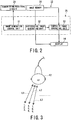
- Fig. 3 is a diagram showing an example of a scan sequence.
- the ultrasonic probe 12 is controlled by the image generation control unit 31 to perform, for a first raster L1, the ultrasonic transmitting and receiving under the first transmitting/receiving condition, then performs the ultrasonic transmitting and receiving under the second transmitting/receiving condition, and then performs the ultrasonic transmitting and receiving under the third transmitting/receiving condition.
- the ultrasonic probe 12 is controlled by the image generation control unit 31 to perform, for a second raster L2, the ultrasonic transmitting and receiving under the first transmitting/receiving condition, then performs the ultrasonic transmitting and receiving under the second transmitting/receiving condition, and then performs the ultrasonic transmitting and receiving under the third transmitting/receiving condition.
- the ultrasonic probe 12 is controlled by the image generation control unit 31 to perform, for a third raster L3, the ultrasonic transmitting and receiving under the first transmitting/receiving condition, then performs the ultrasonic transmitting and receiving under the second transmitting/receiving condition, and then performs the ultrasonic transmitting and receiving under the third transmitting/receiving condition.
- the order of the ultrasonic transmitting and receiving for each raster is not limited to that shown in Fig.
- the image generation control unit 31 shown in Fig. 2 has a function of controlling the signal processing circuit 22 and the image generating circuit 23 to generate a first image (first cross-sectional image, first volume data) based on a received (echo) signal by scanning under the first transmitting/receiving condition, a second image (second cross-sectional image, second volume data) based on a received signal by scanning under the second transmitting/receiving condition, and a third image (third cross-sectional image, third volume data) based on a received signal by scanning under the third transmitting/receiving condition and store the images in the image memory 24.
- first image first cross-sectional image, first volume data
- second image second cross-sectional image, second volume data
- third image third cross-sectional image, third volume data
- the image generation control unit 31 may set transmitting conditions of the first transmitting/receiving condition, the second transmitting/receiving condition, and the third transmitting/receiving condition to be identical, and set receiving conditions thereof to be different.
- three types of images corresponding to the three transmitting/receiving conditions can be obtained by one ultrasonic transmission.
- it takes only one third of transmission time in the case with different transmitting conditions of the first transmitting/receiving condition, the second transmitting/receiving condition, and the third transmitting/receiving condition, and there is an advantage that a differential processing or a composite processing can be performed at a general frame rate (volume rate for volume data).
- the image generation control unit 31 sets the first transmitting/receiving condition as a condition for visualizing a low frequency band of the echo signal, and sets the second transmitting/receiving condition and the third transmitting/receiving condition as conditions for visualizing a relatively narrow and high frequency band of the echo signal.
- the image generation control unit 31 sets a relatively broad beam sound field and a relatively broad receiving opening of the ultrasonic probe 12 as the first transmitting/receiving condition, and sets a relatively narrow beam sound field and a relatively narrow receiving opening of the ultrasonic probe 12 as the second transmitting/receiving condition and the third transmitting/receiving condition.
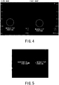
- Fig. 4 is diagrams showing examples of images generated by the image generating circuit 23 controlled by the image generation control unit 31.
- the left side in Fig. 4 shows a third image generated with the puncture needle 11a inserted into an agar phantom as the object P, and the right side in Fig. 4 shows a first image generated with the puncture needle 11a inserted into the agar phantom.
- Fig. 5 is a diagram showing an example of an image of the liver plotted at two points (needle-tip portion of the puncture needle 11a and substantial portion).
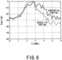
- Fig. 6 is a diagram showing an example of frequency spectrums of RF signals from the needle-tip portion and the substantial portion.
- the RF signal from the needle-tip portion includes fewer high frequency components than the RF signal from the substantial portion other than the needle-tip portion of the puncture needle 11a. This is because fewer harmonic components are generated from the needle-tip portion of the puncture needle 11a, or an ultrasonic beam spreads more at a low frequency to allow reflection signals scattering at the needle-tip portion of the puncture needle 11a to be easily received.
- a visualized frequency band is set to a narrow and relatively high frequency band, an image with fewer signals from the needle-tip portion of the puncture needle 11a can be obtained, which is suitable for the second or third transmitting/receiving condition.
- a relatively low frequency band is visualized, an image with the needle-tip portion of the puncture needle 11a clearly differentiated can be obtained, which is suitable for the first transmitting/receiving condition.
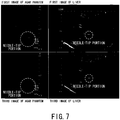
- Fig. 7 is diagrams showing examples of images generated by the image generating circuit 23 controlled by the image generation control unit 31.
- the upper left side in Fig. 7 shows a first image of an agar phantom into which the puncture needle 11a is inserted, generated under the first transmitting/receiving condition
- the lower left side in Fig. 7 shows a third image of the agar phantom into which the puncture needle 11a is inserted, generated under the third transmitting/receiving condition.
- the upper right side in Fig. 7 shows a first image of the liver as a object P, generated under the first transmitting/receiving condition
- the lower right side in Fig. 7 shows a third image of the liver, generated under the third transmitting/receiving condition.
- the differential image generating unit 32 shown in Fig. 2 has a function of performing a differential processing of the first image and the second image stored in the image memory 24 controlled by the image generation control unit 31 to generate a differential image (differential cross-sectional image, differential volume data).
- the differential image generating unit 32 has a function of performing gain correction of the first image and the second image generated by the image generating circuit 23 controlled by the image generation control unit 31 so that the substantial portions have approximately the same brightness, and then performing the differential processing of a first corrected image (first corrected volume data) based on the first image and a second corrected image (second corrected volume data) based on the second image to generate a differential image.
- the differential image generating unit 32 may perform the differential processing based on the first image and the second image converted into a general video format, or based on the first image the second image as RAW data.
- Fig. 8 is diagrams showing examples of the differential images.
- the needle-tip portion of the puncture needle 11a is extracted in the differential image of the agar phantom although a little noise is included, while tissue is canceled in the differential image of the liver.
- the puncture needle 11a is inserted in the living body, only the puncture needle 11a can be extracted in the differential image.
- the composite image generating unit 33 shown in Fig. 2 has a function of executing a composite processing based on the differential image generated by the differential image generating unit 32, and the third image stored in the image memory 24 controlled by the image generation control unit 31 to generate a composite image.
- the composite image generating unit 33 has a function of executing a composite processing based on the first image and the third image stored in the image memory 24 controlled by the image generation control unit 31 to generate a composite image.
- the composite image generating unit 33 performs the composite processing based on predetermined cross-section included in differential volume data as the differential image generated by the differential image generating unit 32, and predetermined cross-section included in third volume data as the third image stored in the image memory 24 controlled by the image generation control unit 31 to generate the composite image.
- Fig. 9 is a diagram showing an example of the composite image.
- Fig. 9 when the differential image formed by the needle-tip portion of the puncture needle 11a is visualized with a different color tone from that of the third image, the operator can easily visually recognize the position of the needle-tip portion of the puncture needle 11a.
- monitoring a path of the puncture needle 11a requires use of a transmitting/receiving condition with lower image quality than that for general observation of the living body by lowering a frequency or spreading the beam so that the needle-tip portion of the puncture needle 11a is easily recognized, which is not suitable for displaying a substantial portion.
- the composite image generating unit 33 when the composite image generating unit 33 generates the composite image to be displayed, the differential image effective for displaying the needle-tip portion of the puncture needle 11a and the third image obtained under the third transmitting/receiving condition effective for displaying the substantial portion can be displayed in a superimposed manner.
- the operator may operate the switch 15b or the like of the operation panel 15 to switch display of the differential image, the composite image, the first image (first corrected image), the second image (second corrected image), and the third image at arbitrary timing.
- the composite image generating unit 33 may set a limited region including a puncture guideline g (shown in Fig. 10 ) of the puncture needle 11a in the differential image to perform the composite processing based on the differential image of the limited region and the third image.
- the composite image generating unit 33 may perform a filtering processing for removing a relatively high frequency band (frequency band higher than a threshold) from the differential image. In this case, the composite image generating unit 33 performs the composite processing based on the differential image after the filtering processing and the third image.
- the composite image generating unit 33 may perform the filtering processing of only the limited region including the puncture guideline G rather than the entire differential image, and perform the composite processing based on the differential image of the limited region after the filtering processing and the third image of the entire region.
- the needle-tip portion of the puncture needle 11a can be easily separated from the substantial portion on the differential image, and thus an actual (present) inserted needle-tip portion of the puncture needle 11a can be detected by positional information of the puncture adaptor 11 including the puncture needle 11a using the differential image.
- the composite image generating unit 33 can recognize the coordinate of the needle-tip portion of the puncture needle 11a based on the differential volume data.
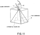
- the composite image generating unit 33 calculates the center of gravity of the needle-tip portion of the puncture needle 11a detected by performing preprocessing such as a noise removal processing or a binarization processing of the differential volume data as a first coordinate [x1, y1, z1] (first coordinate [x1, y1] for the differential cross-sectional image) of the needle-tip portion of the puncture needle 11a. Since the positional relationship between the puncture adaptor 11 and the ultrasonic probe 12 is already known, the composite image generating unit 33 can calculate a second coordinate [x2, y2, z2] on the puncture adaptor 11 through which the needle-tip portion of the puncture needle 11a always passes.
- the composite image generating unit 33 can recognize an actual puncture line G (shown in Fig. 11 ) in the present embodiment passing through the first coordinate and the second coordinate based on the calculated first coordinate and second coordinate in the differential volume data.
- the puncture line G is displayed on the display 14.
- Figs. 12A, 12B and 12C are diagrams showing display examples of a puncture guideline g in the three-dimensional scanning in the related art.
- Fig. 12A shows an image of a first cross-section (A plane) on a preset puncture guideline g
- Fig. 12B shows an image of a second cross-section (cut plane) perpendicular to the first cross-section and on the preset puncture guideline g
- Fig. 12C shows an image of a third cross-section (cut plane) perpendicular to the second cross-section.
- Each image is displayed as a moving image.
- the first coordinate is set in the position of a puncture target where the needle-tip portion of the puncture needle 11a is finally inserted.
- the image of the puncture needle 11a disappears from each image, and the operator cannot visually recognize the position of the puncture needle 11a.
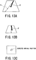
- Figs. 13A, 13B and 13C are diagrams showing display examples of a puncture line G in the three-dimensional scanning in the present embodiment.
- Figs. 13A, 13B and 13C show images having the same cross-sections as in Figs. 12A, 12B and 12C .
- the puncture line G of the puncture needle 11a is calculated based on the first coordinate of the needle-tip portion actually detected by the composite image generating unit 33.
- a projection puncture line G' that is the puncture line G in the three-dimensional coordinate system projected on each cross-section can be displayed as shown in Figs. 13A and 13B .
- Fig. 13A, 13B and 13C show images having the same cross-sections as in Figs. 12A, 12B and 12C .
- the image of the third cross-section can be displayed in a circle around an intersection between the puncture line G and the third cross-section to display an expected arrival position of the needle-tip portion of the puncture needle 11a.
- the operator can ascertain the precise position of the puncture needle 11a, and can perform quick and precise puncture. It may be conceivable that a cross-section position is automatically changed so that the puncture line G is displayed on each cross-section when the puncture needle 11a goes beyond the preset puncture guideline g.
- the image memory 24 is controlled by the image generation control unit 31 to store the first image of a plurality of frames, the second image of a plurality of frames, and the third image of a plurality of frames.
- the composite image generating unit 33 generates a brightness maximum value image holding a maximum value of brightness that changes with time at each pixel based on the differential image, and generates a composite image based on the brightness maximum value image and a live third image.
- the composite image based on the brightness maximum value image and the live third image is sequentially generated and displayed, and thus the locus of the needle-tip portion of the puncture needle 11a is displayed as a moving image when the puncture needle 11a is inserted into the body, thereby increasing visibility of the puncture needle 11a in monitoring the puncture needle 11a.
- the maximum value of brightness is also held for a pixel of a substantial portion, and thus generation of the image holding the maximum value of brightness cannot be used.
- the image generation control unit 31 in the ultrasonic diagnostic apparatus 10 is not limited to the case of generating the first image from the received signal based on the ultrasonic transmitting and receiving by scanning under the first transmitting/receiving condition at the low frequency, and generating the second image from the received signal based on the ultrasonic transmitting and receiving by scanning under the second transmitting/receiving condition at the high frequency.
- the image generation control unit 31 controls the signal processing circuit 22 and the image generating circuit 23 to generate the first image from a fundamental component of the received signal based on the ultrasonic transmitting and receiving by scanning under the first transmitting/receiving condition, and generate the second image from a harmonic component of the received signal.
- Fig. 14 is a diagram to explain the fundamental component and the harmonic component of the received signal.
- Fig. 14 shows a frequency spectrum of the received signal with the abscissa representing the frequency [MHz] and the ordinate representing the signal intensity level [dB].
- the received signal includes the fundamental component and the harmonic component (second harmonic component, third harmonic component).
- the fundamental component of the received signal includes much information on the needle-tip portion of the puncture needle 11a, while the harmonic component of the received signal includes little information on the needle-tip portion of the puncture needle 11a.
- pulse invention may be applied to the image generation control unit 31 shown in Fig. 2 .
- the image generation control unit 31 may control the signal processing circuit 22 and the image generating circuit 23 to generate a first image from the fundamental component of the received signal by scanning under the first transmitting/receiving condition, and generate a second image from a secondary harmonic component of an additional signal of the received signal by scanning under the first transmitting/receiving condition, and the received signal by scanning under the second transmitting/receiving condition, including a transmission pulse waveform having a phase opposite to a transmission pulse waveform included in the first transmitting/receiving condition.
- Fig. 15 is a diagram to explain the additional signal based on the received signals corresponding to two lines.
- the additional signal is obtained by adding the received signal by scanning under the first transmitting/receiving condition on the upper left side and the received signal by scanning under the second transmitting/receiving condition on the lower left side.
- the image of the object P including the needle-tip portion is displayed with only the needle-tip portion of the puncture needle 11a enhanced in monitoring the puncture needle 11a, thereby allowing the operator to easily visually recognize the position of the needle-tip portion.
Description
- The present invention relates to a technique capable of a two-dimensional (2D) scanning and a real time three-dimensional (3D) scanning, and more particularly to an ultrasonic diagnostic apparatus and an ultrasonic diagnostic method that emphatically displays a needle-tip portion of a puncture needle so that an operator can easily visually recognize a position of the needle-tip portion.
- An ultrasonic diagnostic apparatus is a medical diagnostic apparatus that noninvasively obtains tomograms of a soft tissue in a living body from a body surface using an ultrasonic pulse-echo method. The ultrasonic diagnostic apparatus has features that the apparatus is compact and inexpensive, has high safety with no exposure to X-rays, is capable of blood flow imaging, or the like as compared with other medical diagnostic apparatuses, and has been widely used in cardiac, abdominal, urology, obstetrics and gynecology departments, or the like.
- The ultrasonic diagnostic apparatus is used not only for image diagnosis but also, for example, for radiofrequency ablation (RFA) as a local therapy of hepatocellular cancer or a biopsy for hepatocellular tissue examination. Such a therapy and an examination require precise puncture into a region of interest such as a tumor using a puncture needle. Thus, to clearly ascertain where the puncture needle enters in the living body, an ultrasonic diagnostic apparatus that can monitor the region of interest and the puncture needle in real time is used. Particularly, in recent years, the ultrasonic diagnostic apparatus sometimes uses real time three-dimensional ultrasonic images for display because of faster computers. In such a case, some methods have been proposed of displaying a puncture needle position on three-dimensional data during a puncture therapy, or marking a direction of a puncture needle (for example, Japanese Patent Application Publication (Laid-open: KOKAI) No.
6-205776 - In recent years, an ultrasonic diagnostic apparatus capable of a real time volume scanning has also appeared. This apparatus can obtain needle position information in a slice direction of an ultrasonic probe, which has been hard to obtain, and is expected to increase accuracy of a biopsy or an ablation therapy.
- However, the ultrasonic diagnostic apparatus in the related art sometimes has poor visibility because the visualized needle-tip portion of the puncture needle is buried in a background image, or the like, and places a burden on an operator. Also, because of uncertainty about the precise position of the needle-tip portion of the puncture needle, sufficient therapeutic effects may not be obtained such that tissue in a different position from the position of planned tissue is removed or an ablation therapy is performed in a different position.
- When the ultrasonic diagnostic apparatus capable of the real time volume scanning is used, there is a problem that an expected effect cannot be obtained due to insufficient visibility of the needle-tip portion of the puncture needle.
- Further, various studies have been made to increase visibility of a needle-tip portion of a puncture needle, and for example, there is a method using an image processing filter such as edge reinforcement. However, such a method has not been put to practical use because separation of only the needle-tip portion is difficult, and a substantial portion other than the needle-tip portion is influenced.
-
US 2006/0241451 A1 relates to enhancements in the reliability and accuracy of, for example puncture under ultrasonic guide, and more particularly to an ultrasonic diagnostic equipment which is used for the betterment of the visibility of a puncture needle, and a method of controlling the equipment. - The present invention has been achieved in view of such circumstances, and has an object to provide an ultrasonic diagnostic apparatus and an ultrasonic diagnostic method that allows an operator to easily visually recognize the position of a needle-tip portion of a puncture needle in monitoring the puncture needle.
- This is achieved by the ultrasonic diagnostic apparatus according to
claim 1 and the ultrasonic diagnostic method according toclaim 13. Further advantageous embodiments are defined in the dependent claims. - In the accompanying drawings:
-
Fig. 1 is a schematic diagram showing a configuration of ultrasonic diagnostic apparatus of the present embodiment; -
Fig. 2 is a block diagram showing a function of the ultrasonic diagnostic apparatus of the present embodiment; -
Fig. 3 is a diagram showing an example of a scan sequence; -
Fig. 4 is diagrams showing examples of images generated by an image generating circuit controlled by an image generation control unit; -
Fig. 5 is a diagram showing an example of an image of liver plotted at two points (needle-tip portion of puncture needle and substantial portion); -
Fig. 6 is a diagram showing an example of frequency spectrums of RF signals from the needle-tip portion and the substantial portion; -
Fig. 7 is diagrams showing examples of images generated by the image generating circuit controlled by the image generation control unit; -
Fig. 8 is diagrams showing examples of differential images; -
Fig. 9 is a diagram showing an example of a composite image; -
Fig. 10 is a diagram showing a limited region including a puncture guideline of a puncture needle in the differential image; -
Fig. 11 is a diagram showing an actual puncture line of the present embodiment based on a first coordinate and a second coordinate in differential volume data; -
Figs. 12A, 12B, and 12C are diagrams showing display examples of a puncture guideline in a three-dimensional scanning in the related art; -
Figs. 13A, 13B, and 13C are diagrams showing display examples of a puncture line in the three-dimensional scanning in the present embodiment; -
Fig. 14 is a diagram to explain a fundamental component and a harmonic component of a received signal; and -
Fig. 15 is a diagram to explain an additional signal based on the received signals corresponding to two lines. - An embodiment of an ultrasonic diagnostic apparatus and an ultrasonic diagnostic method according to the present invention will be described with reference to the accompanying drawings.
-
Fig. 1 is a schematic diagram showing a configuration of ultrasonic diagnostic apparatus of the present embodiment. -
Fig. 1 shows an ultrasonicdiagnostic apparatus 10 of the present embodiment. The ultrasonicdiagnostic apparatus 10 mainly has apuncture adaptor 11, anultrasonic probe 12, amain body 13, adisplay 14, and anoperation panel 15. - The
puncture adaptor 11 is, for example, secured to theultrasonic probe 12 at a predetermined angle. To thepuncture adaptor 11, apuncture needle 11a to be inserted into a region from a body surface of an object (patient) P to a puncture target (tumor) in the body is mounted. - The
ultrasonic probe 12 has a plurality of piezoelectric transducers that transmit ultrasonic pulses to a two-dimensional or a three-dimensional scanning region including the puncture target of the patient P based on drive pulses from themain body 13, and receive echoes corresponding to the transmitted ultrasonic pulses, and convert the echoes into electric signals. When the piezoelectric transducers in theultrasonic probe 12 transmit the ultrasonic pulses to the scanning region, ultrasonic beams formed by the ultrasonic pulses are successively reflected by a discontinuous surface of acoustic impedance of body tissue. The reflected echoes are received by the piezoelectric transducers. The received echo is converted into an echo signal by the piezoelectric transducers. An amplitude of the echo signal depends on a difference in acoustic impedance on the reflecting discontinuous surface. When the ultrasonic beam is reflected by moving blood flow or a surface such as a cardiac wall, an echo corresponding to the transmitted ultrasonic pulse depends on a speed component in an ultrasonic transmitting direction of a mobile object by the Doppler effect, and undergoes frequency deviation. - The
ultrasonic probe 12 includes, for example, a mechanical three-dimensional probe and a two-dimensional probe (matrix array probe). The mechanical three-dimensional probe is a probe that can mechanically sweep many (for example, 100 to 200) piezoelectric transducers arranged only in an X-axis direction (azimuth direction), or a probe that can mechanically sweep many piezoelectric transducers arranged in the X-axis direction and a few (for example, 3) piezoelectric transducers arranged in a Y-axis direction (elevation direction). The two-dimensional probe is a probe having many piezoelectric transducers arranged in both the X-axis direction and the Y-axis direction. - When the
ultrasonic probe 12 is the mechanical three-dimensional probe, the many piezoelectric transducers arranged in the X-axis direction obtain electronic focus so as to cause the ultrasonic pulse to converge in the X-axis direction to form an appropriate ultrasonic beam extending in a Z-axis direction (depth direction). Meanwhile, when theultrasonic probe 12 is the mechanical three-dimensional probe, it is preferable that an acoustic lens is provided on an ultrasonic irradiation side of one piezoelectric transducer in the Y-axis direction or the piezoelectric transducer is formed as a concave type so as to cause the ultrasonic pulse to converge in the Y-axis direction to form an appropriate ultrasonic beam extending in the Z-axis direction. When theultrasonic probe 12 is the mechanical three-dimensional probe, an acoustic lens is provided on an ultrasonic irradiation side of a few piezoelectric transducers in the Y-axis direction, or the number of driven piezoelectric transducers among the few piezoelectric transducers is changed in the Y-axis direction depending on the position of a focus in the Z-axis direction so as to cause the ultrasonic pulse to converge in the Y-axis direction to form an appropriate ultrasonic beam extending in the Z-axis direction. In scanning a three-dimensional region using the mechanical three-dimensional probe, a plurality of two-dimensional cross-sections (X-Z cross-sections) are scanned by the ultrasonic beam formed by the ultrasonic pulse while the piezoelectric transducers is swept. - When the
ultrasonic probe 12 is the two-dimensional probe, the many piezoelectric transducers arranged in the X-axis direction and the Y-axis direction obtain electronic focus so as to cause the ultrasonic pulse to converge in the X-axis direction and the Y-axis direction to form an appropriate ultrasonic beam extending in the Z-axis direction. In scanning the three-dimensional region using the two-dimensional probe, a plurality of X-Z cross-sections are scanned by the ultrasonic beam formed by the ultrasonic pulse while a transmission surface of the ultrasonic pulse is electronically shifted in the Y-axis direction. - The
main body 13 has a transmitting/receiving circuit 21, asignal processing circuit 22, animage generating circuit 23, animage memory 24, a central processing unit (CPU) 25, amain memory 26, an interface (IF) 27, and astorage 28. In the present embodiment, the transmitting/receivingcircuit 21, thesignal processing circuit 22, and theimage generating circuit 23 are configured as integrated circuits for description, but all or part thereof may function by execution of a modularized software program. - The transmitting/receiving
circuit 21 has a transmitting circuit and a receiving circuit, not shown. The transmitting circuit has a pulser circuit, a transmission delay circuit, a trigger generating circuit, or the like, not shown. The pulser circuit repeatedly generates rate pulses for forming transmitting ultrasonic at a predetermined rate frequency fr [Hz] (cycle: 1/fr [sec]). The transmission delay circuit provides each rate pulse with a delay time required for focusing the ultrasonic into the beam for each channel and determining a transmission directivity. The trigger generating circuit applies a drive pulse to the piezoelectric transducer in theultrasonic probe 12 at timing based on the rate pulse. - The transmitting circuit in the transmitting/receiving
circuit 21 has a function of instantaneously changing a transmission frequency, a transmission drive voltage (sound pressure), a transmission pulse rate, a scanning region, and the number of flashes according to instructions from theCPU 25. Particularly, the sound pressure is changed by a transmitting portion of linear amplifier type that can instantaneously change the value of the sound pressure or a mechanism that electrically switches a plurality of power supply portions. - The receiving circuit in the transmitting/receiving
circuit 21 has an amplifier, a receiving delay circuit, an analog to digital (A/D) conversion circuit, an addition circuit, or the like, not shown. The amplifier amplifies an echo signal captured via theultrasonic probe 12 for each channel. The receiving delay circuit provides the echo signal amplified by the amplifier with a delay time required for determining a receiving directivity. The A/D conversion circuit converts the echo signal output from the receiving delay circuit into a digital signal. The addition circuit performs an addition processing of the digital echo signal. The addition by the addition circuit enhances a reflection component from a direction according to the receiving directivity of the echo signal, the receiving directivity and the transmitting directivity form an overall beam for ultrasonic transmitting and receiving, and a radio frequency (RF) signal is generated. - The
signal processing circuit 22 has a B-mode processing circuit 22a and aDoppler processing circuit 22b. The B-mode processing circuit 22a performs logaritmetic amplification and envelope detection or the like of the RF signal obtained from the transmitting/receivingcircuit 21, and generates a B-mode image with signal intensity expressed by brightness. In this case, a visualized frequency band can be changed by changing a detection frequency. Detection processes with two detection frequencies may be performed for one receiving data in parallel. - The
Doppler processing circuit 22b performs frequency analysis of speed information from the RF signal obtained from the transmitting/receivingcircuit 21, extracts blood flow, tissue, or a contrast medium echo component by the Doppler effect, and calculates blood flow information such as an average speed, dispersion and power for many points. TheDoppler processing circuit 22b generates an average speed image, a dispersion image, and a power image as blood flow information and a Doppler image as a combination thereof. - The
image generating circuit 23 converts a cross-sectional image of a scan line signal sequence of ultrasonic scanning, which is output from thesignal processing circuit 22, into a cross-sectional image of a scan line signal sequence in a general video format typified in, for example, televisions. Theimage generating circuit 23 includes a memory (not shown) that stores an image. For example, after a diagnosis, an operator (or a user) can call up an image recorded during an examination. Further, theimage generating circuit 23 forms volume data on the basis of the cross-sectional images. - The
image memory 24 is a storage device that stores images output from thesignal processing circuit 22 and theimage generating circuit 23. In theimage memory 24, images obtained under different transmitting/receiving conditions are stored in parallel. Theimage memory 24 stores a cross-sectional image of data format before conversion that is referred to as so-called RAW data output from thesignal processing circuit 22, a cross-sectional image of data format after video format conversion output from theimage generating circuit 23, and volume data based on the cross-sectional image of data format after the video format conversion output from theimage generating circuit 23. - The
CPU 25 is a control device having a configuration of an integrated circuit (LSI) in which an electronic circuit configured by a semiconductor is sealed in a package having a plurality of terminals. TheCPU 25 has a function of executing a program stored in themain memory 26. Alternatively, theCPU 25 has a function of loading a program stored in thestorage 28 and a program transferred from a network N, received by theIF 27 and installed in thestorage 28, into themain memory 26, and performing the programs. - The
main memory 26 is a storage device having a configuration that also serves as a read only memory (ROM), a random access memory (RAM), or the like. Themain memory 26 has a function of storing initial program loading (IPL: large scale integration), basic input/output system (BIOS) and data, or temporarily storing a work memory or data of theCPU 25. - The
IF 27 is configured by a connector of parallel connection specifications or serial connection specifications. TheIF 27 is an interface relating to theoperation panel 15, the network N such as a basic local area network (LAN) of a hospital, thestorage 28, or the like. The image generated by themain body 13 can be transferred to other systems via the network N by theIF 27. - The
storage 28 is a storage device having a configuration in which a metal disk with a magnetic material applied or evaporated is irremovably installed in a reading device (not shown). Thestorage 28 has a function of storing a program (including an application program and also an OS (operating system) or the like) installed in themain body 13. The OS may be provided with a graphical user interface (GUI) that can use many graphics in displaying information for the operator, and can perform a basic operation with theoperation panel 15. - The
main memory 26 or thestorage 28 store a control program such as an ultrasonic diagnosis program, diagnosis information (patient identification (ID), doctor's observation, or the like), a diagnosis protocol, a transmitting/receiving condition, and other groups of data. Further, the data stored in themain memory 26 or thestorage 28 can be transferred to the network N via theIF 27. - The
display 14 may be a liquid crystal display or a cathode ray tube (CRT). Thedisplay 14 has a function of displaying two-dimensional data or three-dimensional data together with character information or scales of various parameters based on a video signal from theimage generating circuit 23. - The
operation panel 15 may be atrackball 15a,various switches 15b, abutton 15c, amouse 15d, akeyboard 15e, or the like. Theoperation panel 15 is connected to themain body 13, and has a function of inputting various instructions from the operator, for example, a setting instruction of a region of interest (ROI), a setting instruction of an image quality condition to themain body 13. The operator can input a transmission frequency of the ultrasonic pulse transmitted from theultrasonic probe 12, a transmission drive voltage (sound pressure), a transmission pulse rate, a scanning region, puncture mode start and contrast medium flush instructions, a receiving condition, or the like to themain body 13 via theoperation panel 15. -
Fig. 2 is a block diagram showing a function of the ultrasonicdiagnostic apparatus 10 of the present embodiment. - The
CPU 25 shown inFig. 1 executes a program, and thus the ultrasonicdiagnostic apparatus 10 functions as an imagegeneration control unit 31, a differentialimage generating unit 32, and a compositeimage generating unit 33. The differentialimage generating unit 32 is not a component essential to the ultrasonicdiagnostic apparatus 10. In the present embodiment, theunits 31 to 33 function by execution of a modularized software program for description, but all or part thereof may be configured by hardware such as an integrated circuit. - The image
generation control unit 31 has a function of controlling the transmitting/receivingcircuit 21 so as to sequentially perform, for each raster (scanning line), ultrasonic transmitting and receiving under a first transmitting/receiving condition in which a reflection signal from the needle-tip portion of thepuncture needle 11a is relatively stronger than a substantial portion other than the needle-tip portion, ultrasonic transmitting and receiving under a second transmitting/receiving condition in which the reflection signal from the needle-tip portion of thepuncture needle 11a is relatively weaker than the substantial portion, and ultrasonic transmitting and receiving under a third transmitting/receiving condition different from the first transmitting/receiving condition and the second transmitting/receiving condition. The imagegeneration control unit 31, for example, causes the transmitting/receivingcircuit 21 to perform the ultrasonic transmitting and receiving under the first transmitting/receiving condition at a low frequency, and the ultrasonic transmitting and receiving under the second transmitting/receiving condition at a high frequency. - The image
generation control unit 31 changes at least one of a transmitting condition and a receiving condition included in the transmitting/receiving condition to set the first transmitting/receiving condition, the second transmitting/receiving condition, and the third transmitting/receiving condition. The transmitting condition includes, for example, a frequency (fundamental frequency), a transmission pulse waveform, a transmission pulse phase, a transmission frequency, the number of transmission burst waves, the number of transmission drive elements (transmission opening), a transmission focus (transmission delay), or the like. The receiving condition includes, for example, a receiving frequency, the number of receiving burst waves, the number of receiving drive elements (receiving opening), a receiving focus (receiving delay), or the like. -
Fig. 3 is a diagram showing an example of a scan sequence. - As shown in
Fig. 3 , theultrasonic probe 12 is controlled by the imagegeneration control unit 31 to perform, for a first raster L1, the ultrasonic transmitting and receiving under the first transmitting/receiving condition, then performs the ultrasonic transmitting and receiving under the second transmitting/receiving condition, and then performs the ultrasonic transmitting and receiving under the third transmitting/receiving condition. Then, theultrasonic probe 12 is controlled by the imagegeneration control unit 31 to perform, for a second raster L2, the ultrasonic transmitting and receiving under the first transmitting/receiving condition, then performs the ultrasonic transmitting and receiving under the second transmitting/receiving condition, and then performs the ultrasonic transmitting and receiving under the third transmitting/receiving condition. Then, theultrasonic probe 12 is controlled by the imagegeneration control unit 31 to perform, for a third raster L3, the ultrasonic transmitting and receiving under the first transmitting/receiving condition, then performs the ultrasonic transmitting and receiving under the second transmitting/receiving condition, and then performs the ultrasonic transmitting and receiving under the third transmitting/receiving condition. The order of the ultrasonic transmitting and receiving for each raster is not limited to that shown inFig. 3 , but for example, an order may be conceivable of the ultrasonic transmitting and receiving under the second transmitting/receiving condition, the ultrasonic transmitting and receiving under the third transmitting/receiving condition, and the ultrasonic transmitting and receiving under the first transmitting/receiving condition. - Also, the image
generation control unit 31 shown inFig. 2 has a function of controlling thesignal processing circuit 22 and theimage generating circuit 23 to generate a first image (first cross-sectional image, first volume data) based on a received (echo) signal by scanning under the first transmitting/receiving condition, a second image (second cross-sectional image, second volume data) based on a received signal by scanning under the second transmitting/receiving condition, and a third image (third cross-sectional image, third volume data) based on a received signal by scanning under the third transmitting/receiving condition and store the images in theimage memory 24. - The image
generation control unit 31 may set transmitting conditions of the first transmitting/receiving condition, the second transmitting/receiving condition, and the third transmitting/receiving condition to be identical, and set receiving conditions thereof to be different. In this case, three types of images corresponding to the three transmitting/receiving conditions can be obtained by one ultrasonic transmission. Thus, it takes only one third of transmission time in the case with different transmitting conditions of the first transmitting/receiving condition, the second transmitting/receiving condition, and the third transmitting/receiving condition, and there is an advantage that a differential processing or a composite processing can be performed at a general frame rate (volume rate for volume data). - Also, with the identical transmitting conditions of the first transmitting/receiving condition, the second transmitting/receiving condition, and the third transmitting/receiving condition and the different receiving conditions thereof, the image
generation control unit 31 sets the first transmitting/receiving condition as a condition for visualizing a low frequency band of the echo signal, and sets the second transmitting/receiving condition and the third transmitting/receiving condition as conditions for visualizing a relatively narrow and high frequency band of the echo signal. Alternatively, with the identical transmitting conditions of the first transmitting/receiving condition, the second transmitting/receiving condition, and the third transmitting/receiving condition and the different receiving conditions thereof, the imagegeneration control unit 31 sets a relatively broad beam sound field and a relatively broad receiving opening of theultrasonic probe 12 as the first transmitting/receiving condition, and sets a relatively narrow beam sound field and a relatively narrow receiving opening of theultrasonic probe 12 as the second transmitting/receiving condition and the third transmitting/receiving condition. -
Fig. 4 is diagrams showing examples of images generated by theimage generating circuit 23 controlled by the imagegeneration control unit 31. The left side inFig. 4 shows a third image generated with thepuncture needle 11a inserted into an agar phantom as the object P, and the right side inFig. 4 shows a first image generated with thepuncture needle 11a inserted into the agar phantom. - In the first image on the right side in
Fig. 4 , there is not a large difference in density in the phantom part other than the needle-tip portion of thepuncture needle 11a, but there is a large difference in density in only the needle-tip portion. In the first image on the right side inFig. 4 , the needle-tip portion of thepuncture needle 11a can be clearly differentiated from the phantom part as compared with the third image shown on the left side inFig. 4 . -
Fig. 5 is a diagram showing an example of an image of the liver plotted at two points (needle-tip portion of thepuncture needle 11a and substantial portion).Fig. 6 is a diagram showing an example of frequency spectrums of RF signals from the needle-tip portion and the substantial portion. - As show in
Fig. 6 , the RF signal from the needle-tip portion includes fewer high frequency components than the RF signal from the substantial portion other than the needle-tip portion of thepuncture needle 11a. This is because fewer harmonic components are generated from the needle-tip portion of thepuncture needle 11a, or an ultrasonic beam spreads more at a low frequency to allow reflection signals scattering at the needle-tip portion of thepuncture needle 11a to be easily received. Thus, when a visualized frequency band is set to a narrow and relatively high frequency band, an image with fewer signals from the needle-tip portion of thepuncture needle 11a can be obtained, which is suitable for the second or third transmitting/receiving condition. Meanwhile, when a relatively low frequency band is visualized, an image with the needle-tip portion of thepuncture needle 11a clearly differentiated can be obtained, which is suitable for the first transmitting/receiving condition. -
Fig. 7 is diagrams showing examples of images generated by theimage generating circuit 23 controlled by the imagegeneration control unit 31. - The upper left side in
Fig. 7 shows a first image of an agar phantom into which thepuncture needle 11a is inserted, generated under the first transmitting/receiving condition, and the lower left side inFig. 7 shows a third image of the agar phantom into which thepuncture needle 11a is inserted, generated under the third transmitting/receiving condition. The upper right side inFig. 7 shows a first image of the liver as a object P, generated under the first transmitting/receiving condition, and the lower right side inFig. 7 shows a third image of the liver, generated under the third transmitting/receiving condition. - Comparing the first image and the third image of the agar phantom shown on the upper and lower left sides in
Fig. 7 , the needle-tip portion of thepuncture needle 11a is clearly differentiated in the first image, while the needle-tip portion of thepuncture needle 11a is not clear in the third image as described above. Comparing the first image and the third image of the liver shown on the upper and lower right sides inFig. 7 , few differences are found therebetween although there is a slight difference such as speckle sizes due to a difference in resolution. - The differential
image generating unit 32 shown inFig. 2 has a function of performing a differential processing of the first image and the second image stored in theimage memory 24 controlled by the imagegeneration control unit 31 to generate a differential image (differential cross-sectional image, differential volume data). Alternatively, the differentialimage generating unit 32 has a function of performing gain correction of the first image and the second image generated by theimage generating circuit 23 controlled by the imagegeneration control unit 31 so that the substantial portions have approximately the same brightness, and then performing the differential processing of a first corrected image (first corrected volume data) based on the first image and a second corrected image (second corrected volume data) based on the second image to generate a differential image. Note that the differentialimage generating unit 32 may perform the differential processing based on the first image and the second image converted into a general video format, or based on the first image the second image as RAW data. -
Fig. 8 is diagrams showing examples of the differential images. - From the differential image of the agar phantom shown on the left side in
Fig. 8 and the differential image of the liver shown on the right side inFig. 8 , the needle-tip portion of thepuncture needle 11a is extracted in the differential image of the agar phantom although a little noise is included, while tissue is canceled in the differential image of the liver. Specifically, when thepuncture needle 11a is inserted in the living body, only thepuncture needle 11a can be extracted in the differential image. - The composite
image generating unit 33 shown inFig. 2 has a function of executing a composite processing based on the differential image generated by the differentialimage generating unit 32, and the third image stored in theimage memory 24 controlled by the imagegeneration control unit 31 to generate a composite image. Alternatively, the compositeimage generating unit 33 has a function of executing a composite processing based on the first image and the third image stored in theimage memory 24 controlled by the imagegeneration control unit 31 to generate a composite image. When the three-dimensional scanning is performed under the control by the imagegeneration control unit 31, the compositeimage generating unit 33 performs the composite processing based on predetermined cross-section included in differential volume data as the differential image generated by the differentialimage generating unit 32, and predetermined cross-section included in third volume data as the third image stored in theimage memory 24 controlled by the imagegeneration control unit 31 to generate the composite image. -
Fig. 9 is a diagram showing an example of the composite image. - As shown in
Fig. 9 , when the differential image formed by the needle-tip portion of thepuncture needle 11a is visualized with a different color tone from that of the third image, the operator can easily visually recognize the position of the needle-tip portion of thepuncture needle 11a. In the related art, monitoring a path of thepuncture needle 11a requires use of a transmitting/receiving condition with lower image quality than that for general observation of the living body by lowering a frequency or spreading the beam so that the needle-tip portion of thepuncture needle 11a is easily recognized, which is not suitable for displaying a substantial portion. However, when the compositeimage generating unit 33 generates the composite image to be displayed, the differential image effective for displaying the needle-tip portion of thepuncture needle 11a and the third image obtained under the third transmitting/receiving condition effective for displaying the substantial portion can be displayed in a superimposed manner. Note that the operator may operate theswitch 15b or the like of theoperation panel 15 to switch display of the differential image, the composite image, the first image (first corrected image), the second image (second corrected image), and the third image at arbitrary timing. - When the
puncture needle 11a is actually inserted into the living body as the object P, the substantial portion is not completely cancelled and remains on the differential image in the differential processing by the differentialimage generating unit 32 in some cases. Thus, the compositeimage generating unit 33 may set a limited region including a puncture guideline g (shown inFig. 10 ) of thepuncture needle 11a in the differential image to perform the composite processing based on the differential image of the limited region and the third image. The compositeimage generating unit 33 may perform a filtering processing for removing a relatively high frequency band (frequency band higher than a threshold) from the differential image. In this case, the compositeimage generating unit 33 performs the composite processing based on the differential image after the filtering processing and the third image. The compositeimage generating unit 33 may perform the filtering processing of only the limited region including the puncture guideline G rather than the entire differential image, and perform the composite processing based on the differential image of the limited region after the filtering processing and the third image of the entire region. - With the ultrasonic
diagnostic apparatus 10 of the present embodiment, the needle-tip portion of thepuncture needle 11a can be easily separated from the substantial portion on the differential image, and thus an actual (present) inserted needle-tip portion of thepuncture needle 11a can be detected by positional information of thepuncture adaptor 11 including thepuncture needle 11a using the differential image. Thus, when the differential volume data is generated under the control by the imagegeneration control unit 31, the compositeimage generating unit 33 can recognize the coordinate of the needle-tip portion of thepuncture needle 11a based on the differential volume data. For example, the compositeimage generating unit 33 calculates the center of gravity of the needle-tip portion of thepuncture needle 11a detected by performing preprocessing such as a noise removal processing or a binarization processing of the differential volume data as a first coordinate [x1, y1, z1] (first coordinate [x1, y1] for the differential cross-sectional image) of the needle-tip portion of thepuncture needle 11a. Since the positional relationship between thepuncture adaptor 11 and theultrasonic probe 12 is already known, the compositeimage generating unit 33 can calculate a second coordinate [x2, y2, z2] on thepuncture adaptor 11 through which the needle-tip portion of thepuncture needle 11a always passes. - As described above, the composite
image generating unit 33 can recognize an actual puncture line G (shown inFig. 11 ) in the present embodiment passing through the first coordinate and the second coordinate based on the calculated first coordinate and second coordinate in the differential volume data. The puncture line G is displayed on thedisplay 14. -
Figs. 12A, 12B and 12C are diagrams showing display examples of a puncture guideline g in the three-dimensional scanning in the related art. -
Fig. 12A shows an image of a first cross-section (A plane) on a preset puncture guideline g,Fig. 12B shows an image of a second cross-section (cut plane) perpendicular to the first cross-section and on the preset puncture guideline g, andFig. 12C shows an image of a third cross-section (cut plane) perpendicular to the second cross-section. Each image is displayed as a moving image. With the related art, the first coordinate is set in the position of a puncture target where the needle-tip portion of thepuncture needle 11a is finally inserted. However, if the needle-tip portion of thepuncture needle 11a inserted into the body goes beyond the puncture guideline g, the image of thepuncture needle 11a disappears from each image, and the operator cannot visually recognize the position of thepuncture needle 11a. -
Figs. 13A, 13B and 13C are diagrams showing display examples of a puncture line G in the three-dimensional scanning in the present embodiment. -
Figs. 13A, 13B and 13C show images having the same cross-sections as inFigs. 12A, 12B and 12C . The puncture line G of thepuncture needle 11a is calculated based on the first coordinate of the needle-tip portion actually detected by the compositeimage generating unit 33. Thus, when the puncture line G is in a three-dimensional coordinate system, a projection puncture line G' that is the puncture line G in the three-dimensional coordinate system projected on each cross-section can be displayed as shown inFigs. 13A and 13B . As show inFig. 13C , the image of the third cross-section can be displayed in a circle around an intersection between the puncture line G and the third cross-section to display an expected arrival position of the needle-tip portion of thepuncture needle 11a. Thus, the operator can ascertain the precise position of thepuncture needle 11a, and can perform quick and precise puncture. It may be conceivable that a cross-section position is automatically changed so that the puncture line G is displayed on each cross-section when thepuncture needle 11a goes beyond the preset puncture guideline g. - The
image memory 24 is controlled by the imagegeneration control unit 31 to store the first image of a plurality of frames, the second image of a plurality of frames, and the third image of a plurality of frames. The compositeimage generating unit 33 generates a brightness maximum value image holding a maximum value of brightness that changes with time at each pixel based on the differential image, and generates a composite image based on the brightness maximum value image and a live third image. The composite image based on the brightness maximum value image and the live third image is sequentially generated and displayed, and thus the locus of the needle-tip portion of thepuncture needle 11a is displayed as a moving image when thepuncture needle 11a is inserted into the body, thereby increasing visibility of thepuncture needle 11a in monitoring thepuncture needle 11a. When an image holding a maximum value of brightness is generated using a third image in the related art, the maximum value of brightness is also held for a pixel of a substantial portion, and thus generation of the image holding the maximum value of brightness cannot be used. - The image
generation control unit 31 in the ultrasonicdiagnostic apparatus 10 is not limited to the case of generating the first image from the received signal based on the ultrasonic transmitting and receiving by scanning under the first transmitting/receiving condition at the low frequency, and generating the second image from the received signal based on the ultrasonic transmitting and receiving by scanning under the second transmitting/receiving condition at the high frequency. For example, it may be conceivable that the imagegeneration control unit 31 controls thesignal processing circuit 22 and theimage generating circuit 23 to generate the first image from a fundamental component of the received signal based on the ultrasonic transmitting and receiving by scanning under the first transmitting/receiving condition, and generate the second image from a harmonic component of the received signal. -
Fig. 14 is a diagram to explain the fundamental component and the harmonic component of the received signal. -
Fig. 14 shows a frequency spectrum of the received signal with the abscissa representing the frequency [MHz] and the ordinate representing the signal intensity level [dB]. As shown inFig. 14 , the received signal includes the fundamental component and the harmonic component (second harmonic component, third harmonic component). The fundamental component of the received signal includes much information on the needle-tip portion of thepuncture needle 11a, while the harmonic component of the received signal includes little information on the needle-tip portion of thepuncture needle 11a. - Further, pulse invention may be applied to the image
generation control unit 31 shown inFig. 2 . The imagegeneration control unit 31 may control thesignal processing circuit 22 and theimage generating circuit 23 to generate a first image from the fundamental component of the received signal by scanning under the first transmitting/receiving condition, and generate a second image from a secondary harmonic component of an additional signal of the received signal by scanning under the first transmitting/receiving condition, and the received signal by scanning under the second transmitting/receiving condition, including a transmission pulse waveform having a phase opposite to a transmission pulse waveform included in the first transmitting/receiving condition. -
Fig. 15 is a diagram to explain the additional signal based on the received signals corresponding to two lines. - As shown in
Fig. 15 , the additional signal is obtained by adding the received signal by scanning under the first transmitting/receiving condition on the upper left side and the received signal by scanning under the second transmitting/receiving condition on the lower left side. - According to the ultrasonic
diagnostic apparatus 10 of the present embodiment, the image of the object P including the needle-tip portion is displayed with only the needle-tip portion of thepuncture needle 11a enhanced in monitoring thepuncture needle 11a, thereby allowing the operator to easily visually recognize the position of the needle-tip portion. - It is explicitly stated that all features disclosed in the description and/or the claims are intended to be disclosed separately and independently from each other for the purpose of original disclosure as well as for the purpose of restricting the claimed invention independent of the composition of the features in the embodiments and/or the claims. It is explicitly stated that all value ranges or indications. of groups of entities disclose every possible intermediate value or intermediate entity for the purpose of original disclosure as well as for the purpose of restricting the claimed invention, in particular as limits of value ranges.
Claims (13)
- An ultrasonic diagnostic apparatus for imaging a needle, comprising:an ultrasonic probe (12) configured to transmit an ultrasonic pulse to a two-dimensional scanning region or a three-dimensional scanning region including a needle-tip portion of a puncture needle (11a to be inserted in an object and receive an echo corresponding to the ultrasonic pulse as a received signal;a control unit (31) configured to control the ultrasonic probe (12) so as to sequentially perform, for each scanning line in the scanning region, the transmitting and receiving under a first condition where a frequency band is low, and the transmitting and receiving under a second condition and the transmitting and receiving under a third condition both where frequency bands are higher than under the first condition, or the transmitting and receiving under a first condition where a beam sound field is broad, and the transmitting and receiving under a second condition and the transmitting and receiving under a third condition both where beam sound fields are narrower than under the first condition;a basic image generating unit (31) configured to generate a first image based on the received signal under the first condition, a second image based on the received signal under the second condition, and a third image based on the received signal under the third condition;a differential image generating unit (32) configured to perform a differential processing based on the first image and the second image to generate a differential image; anda composite image generating unit (33) configured to perform a composite processing based on the differential image and the third image to generate a composite image.
- The ultrasonic diagnostic apparatus according to claim 1, wherein
the control unit (31) is configured to cause the ultrasonic probe (12) to perform the transmitting and receiving under the first condition in which an echo from the needle-tip portion is relatively stronger than a substantial portion other than the needle-tip portion, and the second condition in which the echo from the needle-tip portion of the puncture needle is relatively weaker than the substantial portion. - The ultrasonic diagnostic apparatus according to claim 1 or 2, further comprising a correction unit configured to perform a gain correction processing based on the first image and the second image to generate a first corrected image and a second corrected image, wherein
the differential image generating unit (32) is configured to perform the differential processing based on the first corrected image and the second corrected image. - The ultrasonic diagnostic apparatus according to claim 2 or 3, wherein
the composite image generating unit (33) is configured to set a limited region including a guideline of the puncture needle in the first image or the differential image, and
the composite image generating unit (33) is configured to perform the composite processing based on the limited region, set in the first image or the differential image, and the entire region of the third image. - The ultrasonic diagnostic apparatus according to one of claims 2 to 4, further comprising a filtering unit configured to perform a filtering processing for removing a frequency band higher than a threshold from the first image or the differential image, wherein
the composite image generating unit (33) is configured to perform the composite processing based on the filtered first image or the filtered differential image, and the third image. - The ultrasonic diagnostic apparatus according to claim 5, wherein
the filtering unit is configured to perform the filtering processing based on only a limited region including a guideline of the puncture needle, and
the composite image generating unit (33) is configured to perform the composite processing based on the limited region set in the filtered first image or the filtered differential image, and the entire region of the third image. - The ultrasonic diagnostic apparatus according to one of claims 1 to 6, wherein
the basic image generating unit (31) is configured to generate the first images corresponding to a plurality of frames, the second images corresponding to a plurality of frames, and the third images corresponding to a plurality of frames, respectively. - The ultrasonic diagnostic apparatus according to claim 7, wherein
the composite image generating unit (33) is configured to generate, every frame of the frames, a brightness maximum value image holding a maximum value of brightness that changes with time at each pixel based on the first image or the differential image, and to perform the composite processing based on the brightness maximum value image and the third image. - The ultrasonic diagnostic apparatus according to one of claims 1 to 8, wherein
the basic image generating unit (33) is configured to generate first volume data as the first image based on a plurality of cross-sectional images relating to the three-dimensional scanning region under the first condition, to generate second volume data as the second image based on a plurality of cross-sectional images relating to the three-dimensional scanning region under the second condition, and to generate third volume data as the third image based on a plurality of cross-sectional images relating to the three-dimensional scanning region under the third condition. - The ultrasonic diagnostic apparatus according to claim 9, further comprising an addition unit configured to detect a position of the needle-tip portion based on the first volume data, or differential volume data based on the first volume data and the second volume data, calculate a puncture line of the puncture needle in the three-dimensional scanning region based on the position of the needle-tip portion and positional information of a puncture adaptor including the puncture needle, and add the puncture line to the composite image.
- The ultrasonic diagnostic apparatus according to claim 10, wherein
the composite image generating unit (33) is configured to generate three cross-sectional images perpendicular to each other as the composite image, and to project the position of the needle-tip portion on the three cross-sectional images. - The ultrasonic diagnostic apparatus according to claim 2, wherein
the control unit (31) is configured to set transmitting conditions of the first transmitting/receiving condition, the second transmitting/receiving condition, and the third transmitting/receiving condition to be identical, and to set receiving conditions thereof to be different. - An ultrasonic diagnostic method for imaging a needle comprising steps of:controlling an ultrasonic probe (12) to transmit an ultrasonic pulse to a two-dimensional scanning region or a three-dimensional scanning region including a needle-tip portion of a puncture needle (11a to be inserted in an object, and to receive an echo corresponding to the ultrasonic pulse as a received signal so as to sequentially perform, for each scanning line in the scanning region, the transmitting and receiving under a first condition where a frequency band is low, and the transmitting and receiving under a second condition and the transmitting and receiving under a third condition both where frequency bands are higher than under the first condition, or the transmitting and receiving under a first condition where a beam sound field is broad, and the transmitting and receiving under a second condition and the transmitting and receiving under a third condition both where beam sound fields are narrower than under the first condition;basic image generating of a first image based on the received signal under the first condition, a second image based on the received signal under the second condition, and a third image based on the received signal under the third condition;differential image generating by performing a differential processing based on the first image and the second image to generate a differential image; andcomposite image generating by performing a composite processing based on the differential image and the third image to generate a composite image.
Applications Claiming Priority (1)
| Application Number | Priority Date | Filing Date | Title |
|---|---|---|---|
| JP2009028034A JP5438985B2 (en) | 2009-02-10 | 2009-02-10 | Ultrasonic diagnostic apparatus and control program for ultrasonic diagnostic apparatus |
Publications (2)
| Publication Number | Publication Date |
|---|---|
| EP2215969A1 EP2215969A1 (en) | 2010-08-11 |
| EP2215969B1 true EP2215969B1 (en) | 2016-12-21 |
Family
ID=42133512
Family Applications (1)
| Application Number | Title | Priority Date | Filing Date |
|---|---|---|---|
| EP10001322.6A Active EP2215969B1 (en) | 2009-02-10 | 2010-02-09 | Ultrasonic diagnostic apparatus and ultrasonic diagnostic method |
Country Status (4)
| Country | Link |
|---|---|
| US (1) | US9119558B2 (en) |
| EP (1) | EP2215969B1 (en) |
| JP (1) | JP5438985B2 (en) |
| CN (1) | CN101797167B (en) |
Families Citing this family (32)
| Publication number | Priority date | Publication date | Assignee | Title |
|---|---|---|---|---|
| US9184369B2 (en) | 2008-09-18 | 2015-11-10 | Fujifilm Sonosite, Inc. | Methods for manufacturing ultrasound transducers and other components |
| US8663110B2 (en) | 2009-11-17 | 2014-03-04 | Samsung Medison Co., Ltd. | Providing an optimal ultrasound image for interventional treatment in a medical system |
| JP5645628B2 (en) * | 2010-12-09 | 2014-12-24 | 富士フイルム株式会社 | Ultrasonic diagnostic equipment |
| EP2454996A1 (en) * | 2010-11-17 | 2012-05-23 | Samsung Medison Co., Ltd. | Providing an optimal ultrasound image for interventional treatment in a medical system |
| CN102525547A (en) * | 2010-12-27 | 2012-07-04 | 通用电气公司 | Method and device for enhancing needle visualization in ultrasonic imaging |
| JP5778429B2 (en) * | 2011-01-04 | 2015-09-16 | 株式会社東芝 | Ultrasonic diagnostic equipment |
| JP6000569B2 (en) * | 2011-04-01 | 2016-09-28 | 東芝メディカルシステムズ株式会社 | Ultrasonic diagnostic apparatus and control program |
| JP6109498B2 (en) * | 2011-07-05 | 2017-04-05 | 東芝メディカルシステムズ株式会社 | Ultrasonic diagnostic apparatus and ultrasonic diagnostic apparatus control program |
| JP2013081764A (en) * | 2011-09-27 | 2013-05-09 | Toshiba Corp | Ultrasonic diagnostic apparatus and ultrasonic scanning method |
| JP5719275B2 (en) * | 2011-10-25 | 2015-05-13 | オリンパスメディカルシステムズ株式会社 | Ultrasound endoscope system |
| KR101468418B1 (en) | 2012-01-13 | 2014-12-03 | 삼성메디슨 주식회사 | Method and apparatus for processing ultrasound images |
| JP5645856B2 (en) * | 2012-01-30 | 2014-12-24 | ジーイー・メディカル・システムズ・グローバル・テクノロジー・カンパニー・エルエルシー | Transmission / reception circuit, ultrasonic probe, and ultrasonic image display device |
| JP5929368B2 (en) * | 2012-03-16 | 2016-06-01 | コニカミノルタ株式会社 | Ultrasound diagnostic imaging equipment |
| JP5507018B1 (en) * | 2012-07-27 | 2014-05-28 | オリンパスメディカルシステムズ株式会社 | Ultrasonic observation apparatus, operation method of ultrasonic observation apparatus, and operation program of ultrasonic observation apparatus |
| WO2014065338A1 (en) * | 2012-10-23 | 2014-05-01 | 株式会社 東芝 | Ultrasonic diagnostic device and ultrasonic diagnostic device control method |
| CN103845075B (en) * | 2012-11-30 | 2016-09-28 | 通用电气公司 | Vltrasonic device and ultrasonic imaging method |
| JP6450328B2 (en) * | 2013-03-15 | 2019-01-09 | コナヴィ メディカル インコーポレーテッド | Active localization and visualization of minimally invasive devices using ultrasound |
| GB201304798D0 (en) | 2013-03-15 | 2013-05-01 | Univ Dundee | Medical apparatus visualisation |
| JP6114663B2 (en) * | 2013-08-27 | 2017-04-12 | 富士フイルム株式会社 | Ultrasonic diagnostic apparatus and ultrasonic image generation method |
| JP6207956B2 (en) * | 2013-10-03 | 2017-10-04 | 東芝メディカルシステムズ株式会社 | Ultrasonic diagnostic equipment |
| JP6405712B2 (en) * | 2014-05-30 | 2018-10-17 | コニカミノルタ株式会社 | Ultrasonic diagnostic equipment |
| CN104162223B (en) * | 2014-08-27 | 2017-01-11 | 深圳开立生物医疗科技股份有限公司 | Puncture guide wire arranging method, device and system |
| US10070837B2 (en) * | 2014-10-10 | 2018-09-11 | Canon Kabushiki Kaisha | Medical imaging apparatus, program installable in medical imaging apparatus, and medical imaging method |
| KR102035991B1 (en) * | 2015-01-16 | 2019-10-25 | 지멘스 메디컬 솔루션즈 유에스에이, 인크. | Method and ultrasound system for generating image of target object |
| WO2017029830A1 (en) * | 2015-08-20 | 2017-02-23 | コニカミノルタ株式会社 | Ultrasonic diagnostic imaging apparatus |
| JP6172330B2 (en) * | 2016-05-06 | 2017-08-02 | コニカミノルタ株式会社 | Ultrasound diagnostic imaging equipment |
| CN106236140B (en) * | 2016-08-25 | 2019-11-08 | 成都优途科技有限公司 | A kind of ultrasonic imaging method, apparatus and system |
| KR20180066781A (en) * | 2016-12-09 | 2018-06-19 | 삼성전자주식회사 | Method and apparatus for displaying medical image |
| CN107126260B (en) * | 2017-07-18 | 2019-09-13 | 深圳开立生物医疗科技股份有限公司 | Method for ultrasonic imaging, system and supersonic imaging apparatus |
| JP6800109B2 (en) * | 2017-08-22 | 2020-12-16 | オリンパス株式会社 | Endoscopic ultrasound |
| TWI743411B (en) * | 2017-11-08 | 2021-10-21 | 美商富士膠片索諾聲公司 | Ultrasound system with high frequency detail |
| EP3973896A4 (en) * | 2020-02-04 | 2023-07-12 | Tianli Zhao | Puncture needle positioning system and method |
Family Cites Families (13)
| Publication number | Priority date | Publication date | Assignee | Title |
|---|---|---|---|---|
| US4835712A (en) * | 1986-04-14 | 1989-05-30 | Pixar | Methods and apparatus for imaging volume data with shading |
| JP3251682B2 (en) | 1993-01-11 | 2002-01-28 | 株式会社東芝 | Ultrasound diagnostic equipment |
| US5761331A (en) * | 1995-06-05 | 1998-06-02 | Intellectual Property Group Of Pillsbury Madison & Sutro Llp | Method and apparatus for tomographic imaging and image reconstruction using recombinant transverse phase differentials |
| JP2001061841A (en) * | 1999-08-30 | 2001-03-13 | Toshiba Corp | Ultrasonograph, and method of producing ultrasonic image |
| JP2004141514A (en) * | 2002-10-28 | 2004-05-20 | Toshiba Corp | Image processing apparatus and ultrasonic diagnostic apparatus |
| JP4786150B2 (en) * | 2004-07-07 | 2011-10-05 | 株式会社東芝 | Ultrasonic diagnostic apparatus and image processing apparatus |
| WO2006043639A1 (en) | 2004-10-20 | 2006-04-27 | Kabushiki Kaisha Toshiba | Ultrasonic diagnostic equipment and control method therefor |
| JP2006150069A (en) * | 2004-10-20 | 2006-06-15 | Toshiba Corp | Ultrasonic diagnostic equipment, and control method therefor |
| JP4590293B2 (en) * | 2005-04-11 | 2010-12-01 | 富士フイルム株式会社 | Ultrasonic observation equipment |
| JP4381344B2 (en) * | 2005-05-17 | 2009-12-09 | ジーイー・メディカル・システムズ・グローバル・テクノロジー・カンパニー・エルエルシー | Ultrasonic diagnostic equipment |
| WO2007114375A1 (en) * | 2006-03-31 | 2007-10-11 | Kabushiki Kaisha Toshiba | Ultrasound diagnostic device and control method for ultrasound diagnostic device |
| JP4891651B2 (en) * | 2006-05-11 | 2012-03-07 | 日立アロカメディカル株式会社 | Ultrasonic diagnostic equipment |
| JP2008012150A (en) * | 2006-07-07 | 2008-01-24 | Toshiba Corp | Ultrasonic diagnostic equipment and control program of ultrasonic diagnostic equipment |
-
2009
- 2009-02-10 JP JP2009028034A patent/JP5438985B2/en active Active
-
2010
- 2010-01-27 CN CN2010101041104A patent/CN101797167B/en active Active
- 2010-02-09 EP EP10001322.6A patent/EP2215969B1/en active Active
- 2010-02-12 US US12/705,074 patent/US9119558B2/en active Active
Non-Patent Citations (1)
| Title |
|---|
| None * |
Also Published As
| Publication number | Publication date |
|---|---|
| JP2010183935A (en) | 2010-08-26 |
| JP5438985B2 (en) | 2014-03-12 |
| CN101797167A (en) | 2010-08-11 |
| US9119558B2 (en) | 2015-09-01 |
| CN101797167B (en) | 2012-11-14 |
| US20100204579A1 (en) | 2010-08-12 |
| EP2215969A1 (en) | 2010-08-11 |
Similar Documents
| Publication | Publication Date | Title |
|---|---|---|
| EP2215969B1 (en) | Ultrasonic diagnostic apparatus and ultrasonic diagnostic method | |
| US10278670B2 (en) | Ultrasound diagnostic apparatus and method of controlling ultrasound diagnostic apparatus | |
| US10743845B2 (en) | Ultrasound diagnostic apparatus and method for distinguishing a low signal/noise area in an ultrasound image | |
| US9610094B2 (en) | Method and apparatus for ultrasonic diagnosis | |
| US20060173327A1 (en) | Ultrasound diagnostic system and method of forming arbitrary M-mode images | |
| US10231710B2 (en) | Ultrasound diagnosis apparatus and ultrasound imaging method | |
| JP7461530B2 (en) | Ultrasound diagnostic device and puncture support program | |
| WO2007114375A1 (en) | Ultrasound diagnostic device and control method for ultrasound diagnostic device | |
| JP2009089736A (en) | Ultrasonograph | |
| EP2402745B1 (en) | Ultrasound diagnosis apparatus, image processing apparatus and image processing method | |
| JP2006314689A (en) | Ultrasonic diagnostic system and its control program | |
| JP2010148828A (en) | Ultrasonic diagnostic device and control program of ultrasonic diagnostic device | |
| US11219429B2 (en) | Ultrasound imaging apparatus and controlling method for the same | |
| JP2007195867A (en) | Ultrasonic diagnostic equipment and ultrasonic image display program | |
| JP2003260056A (en) | Ultrasonograph | |
| JP2005319199A (en) | Ultrasonic diagnostic apparatus | |
| JP5121384B2 (en) | Ultrasonic diagnostic equipment | |
| JP5142675B2 (en) | Ultrasonic diagnostic apparatus and ultrasonic diagnostic apparatus control program | |
| JP6780976B2 (en) | Ultrasonic diagnostic equipment | |
| JP2000166918A (en) | Ultrasonograph | |
| JP2007117566A (en) | Ultrasonic diagnostic equipment and control method for it | |
| KR20200043048A (en) | Ultrasound imaging apparatus and control method for the same | |
| JP6207956B2 (en) | Ultrasonic diagnostic equipment | |
| JP5583892B2 (en) | Ultrasonic diagnostic equipment | |
| JP2006346176A (en) | Ultrasonic diagnostic device and image display device |
Legal Events
| Date | Code | Title | Description |
|---|---|---|---|
| PUAI | Public reference made under article 153(3) epc to a published international application that has entered the european phase |
Free format text: ORIGINAL CODE: 0009012 |
|
| 17P | Request for examination filed |
Effective date: 20100209 |
|
| AK | Designated contracting states |
Kind code of ref document: A1 Designated state(s): AT BE BG CH CY CZ DE DK EE ES FI FR GB GR HR HU IE IS IT LI LT LU LV MC MK MT NL NO PL PT RO SE SI SK SM TR |
|
| AX | Request for extension of the european patent |
Extension state: AL BA RS |
|
| 17Q | First examination report despatched |
Effective date: 20130426 |
|
| 17Q | First examination report despatched |
Effective date: 20140915 |
|
| GRAP | Despatch of communication of intention to grant a patent |
Free format text: ORIGINAL CODE: EPIDOSNIGR1 |
|
| RAP1 | Party data changed (applicant data changed or rights of an application transferred) |
Owner name: TOSHIBA MEDICAL SYSTEMS CORPORATION |
|
| INTG | Intention to grant announced |
Effective date: 20160704 |
|
| GRAS | Grant fee paid |
Free format text: ORIGINAL CODE: EPIDOSNIGR3 |
|
| GRAJ | Information related to disapproval of communication of intention to grant by the applicant or resumption of examination proceedings by the epo deleted |
Free format text: ORIGINAL CODE: EPIDOSDIGR1 |
|
| GRAL | Information related to payment of fee for publishing/printing deleted |
Free format text: ORIGINAL CODE: EPIDOSDIGR3 |
|
| INTC | Intention to grant announced (deleted) | ||
| GRAR | Information related to intention to grant a patent recorded |
Free format text: ORIGINAL CODE: EPIDOSNIGR71 |
|
| GRAA | (expected) grant |
Free format text: ORIGINAL CODE: 0009210 |
|
| AK | Designated contracting states |
Kind code of ref document: B1 Designated state(s): AT BE BG CH CY CZ DE DK EE ES FI FR GB GR HR HU IE IS IT LI LT LU LV MC MK MT NL NO PL PT RO SE SI SK SM TR |
|
| INTG | Intention to grant announced |
Effective date: 20161115 |
|
| REG | Reference to a national code |
Ref country code: GB Ref legal event code: FG4D |
|
| REG | Reference to a national code |
Ref country code: CH Ref legal event code: EP |
|
| REG | Reference to a national code |
Ref country code: IE Ref legal event code: FG4D |
|
| REG | Reference to a national code |
Ref country code: AT Ref legal event code: REF Ref document number: 854751 Country of ref document: AT Kind code of ref document: T Effective date: 20170115 |
|
| REG | Reference to a national code |
Ref country code: DE Ref legal event code: R096 Ref document number: 602010038902 Country of ref document: DE |
|
| PG25 | Lapsed in a contracting state [announced via postgrant information from national office to epo] |
Ref country code: LV Free format text: LAPSE BECAUSE OF FAILURE TO SUBMIT A TRANSLATION OF THE DESCRIPTION OR TO PAY THE FEE WITHIN THE PRESCRIBED TIME-LIMIT Effective date: 20161221 |
|
| REG | Reference to a national code |
Ref country code: NL Ref legal event code: FP |
|
| REG | Reference to a national code |
Ref country code: LT Ref legal event code: MG4D |
|
| PG25 | Lapsed in a contracting state [announced via postgrant information from national office to epo] |
Ref country code: LT Free format text: LAPSE BECAUSE OF FAILURE TO SUBMIT A TRANSLATION OF THE DESCRIPTION OR TO PAY THE FEE WITHIN THE PRESCRIBED TIME-LIMIT Effective date: 20161221 Ref country code: NO Free format text: LAPSE BECAUSE OF FAILURE TO SUBMIT A TRANSLATION OF THE DESCRIPTION OR TO PAY THE FEE WITHIN THE PRESCRIBED TIME-LIMIT Effective date: 20170321 Ref country code: GR Free format text: LAPSE BECAUSE OF FAILURE TO SUBMIT A TRANSLATION OF THE DESCRIPTION OR TO PAY THE FEE WITHIN THE PRESCRIBED TIME-LIMIT Effective date: 20170322 Ref country code: SE Free format text: LAPSE BECAUSE OF FAILURE TO SUBMIT A TRANSLATION OF THE DESCRIPTION OR TO PAY THE FEE WITHIN THE PRESCRIBED TIME-LIMIT Effective date: 20161221 |
|
| REG | Reference to a national code |
Ref country code: AT Ref legal event code: MK05 Ref document number: 854751 Country of ref document: AT Kind code of ref document: T Effective date: 20161221 |
|
| PG25 | Lapsed in a contracting state [announced via postgrant information from national office to epo] |
Ref country code: HR Free format text: LAPSE BECAUSE OF FAILURE TO SUBMIT A TRANSLATION OF THE DESCRIPTION OR TO PAY THE FEE WITHIN THE PRESCRIBED TIME-LIMIT Effective date: 20161221 Ref country code: FI Free format text: LAPSE BECAUSE OF FAILURE TO SUBMIT A TRANSLATION OF THE DESCRIPTION OR TO PAY THE FEE WITHIN THE PRESCRIBED TIME-LIMIT Effective date: 20161221 Ref country code: BE Free format text: LAPSE BECAUSE OF NON-PAYMENT OF DUE FEES Effective date: 20170228 |
|
| PG25 | Lapsed in a contracting state [announced via postgrant information from national office to epo] |
Ref country code: EE Free format text: LAPSE BECAUSE OF FAILURE TO SUBMIT A TRANSLATION OF THE DESCRIPTION OR TO PAY THE FEE WITHIN THE PRESCRIBED TIME-LIMIT Effective date: 20161221 Ref country code: SK Free format text: LAPSE BECAUSE OF FAILURE TO SUBMIT A TRANSLATION OF THE DESCRIPTION OR TO PAY THE FEE WITHIN THE PRESCRIBED TIME-LIMIT Effective date: 20161221 Ref country code: RO Free format text: LAPSE BECAUSE OF FAILURE TO SUBMIT A TRANSLATION OF THE DESCRIPTION OR TO PAY THE FEE WITHIN THE PRESCRIBED TIME-LIMIT Effective date: 20161221 Ref country code: IS Free format text: LAPSE BECAUSE OF FAILURE TO SUBMIT A TRANSLATION OF THE DESCRIPTION OR TO PAY THE FEE WITHIN THE PRESCRIBED TIME-LIMIT Effective date: 20170421 Ref country code: CZ Free format text: LAPSE BECAUSE OF FAILURE TO SUBMIT A TRANSLATION OF THE DESCRIPTION OR TO PAY THE FEE WITHIN THE PRESCRIBED TIME-LIMIT Effective date: 20161221 |
|
| PG25 | Lapsed in a contracting state [announced via postgrant information from national office to epo] |
Ref country code: SM Free format text: LAPSE BECAUSE OF FAILURE TO SUBMIT A TRANSLATION OF THE DESCRIPTION OR TO PAY THE FEE WITHIN THE PRESCRIBED TIME-LIMIT Effective date: 20161221 Ref country code: BE Free format text: LAPSE BECAUSE OF FAILURE TO SUBMIT A TRANSLATION OF THE DESCRIPTION OR TO PAY THE FEE WITHIN THE PRESCRIBED TIME-LIMIT Effective date: 20161221 Ref country code: PL Free format text: LAPSE BECAUSE OF FAILURE TO SUBMIT A TRANSLATION OF THE DESCRIPTION OR TO PAY THE FEE WITHIN THE PRESCRIBED TIME-LIMIT Effective date: 20161221 Ref country code: ES Free format text: LAPSE BECAUSE OF FAILURE TO SUBMIT A TRANSLATION OF THE DESCRIPTION OR TO PAY THE FEE WITHIN THE PRESCRIBED TIME-LIMIT Effective date: 20161221 Ref country code: IT Free format text: LAPSE BECAUSE OF FAILURE TO SUBMIT A TRANSLATION OF THE DESCRIPTION OR TO PAY THE FEE WITHIN THE PRESCRIBED TIME-LIMIT Effective date: 20161221 Ref country code: AT Free format text: LAPSE BECAUSE OF FAILURE TO SUBMIT A TRANSLATION OF THE DESCRIPTION OR TO PAY THE FEE WITHIN THE PRESCRIBED TIME-LIMIT Effective date: 20161221 Ref country code: PT Free format text: LAPSE BECAUSE OF FAILURE TO SUBMIT A TRANSLATION OF THE DESCRIPTION OR TO PAY THE FEE WITHIN THE PRESCRIBED TIME-LIMIT Effective date: 20170421 Ref country code: BG Free format text: LAPSE BECAUSE OF FAILURE TO SUBMIT A TRANSLATION OF THE DESCRIPTION OR TO PAY THE FEE WITHIN THE PRESCRIBED TIME-LIMIT Effective date: 20170321 |
|
| REG | Reference to a national code |
Ref country code: DE Ref legal event code: R097 Ref document number: 602010038902 Country of ref document: DE |
|
| PG25 | Lapsed in a contracting state [announced via postgrant information from national office to epo] |
Ref country code: MC Free format text: LAPSE BECAUSE OF FAILURE TO SUBMIT A TRANSLATION OF THE DESCRIPTION OR TO PAY THE FEE WITHIN THE PRESCRIBED TIME-LIMIT Effective date: 20161221 |
|
| REG | Reference to a national code |
Ref country code: CH Ref legal event code: PL |
|
| PLBE | No opposition filed within time limit |
Free format text: ORIGINAL CODE: 0009261 |
|
| STAA | Information on the status of an ep patent application or granted ep patent |
Free format text: STATUS: NO OPPOSITION FILED WITHIN TIME LIMIT |
|
| PG25 | Lapsed in a contracting state [announced via postgrant information from national office to epo] |
Ref country code: LI Free format text: LAPSE BECAUSE OF NON-PAYMENT OF DUE FEES Effective date: 20170228 Ref country code: CH Free format text: LAPSE BECAUSE OF NON-PAYMENT OF DUE FEES Effective date: 20170228 |
|
| 26N | No opposition filed |
Effective date: 20170922 |
|
| GBPC | Gb: european patent ceased through non-payment of renewal fee |
Effective date: 20170321 |
|
| REG | Reference to a national code |
Ref country code: IE Ref legal event code: MM4A |
|
| PG25 | Lapsed in a contracting state [announced via postgrant information from national office to epo] |
Ref country code: DK Free format text: LAPSE BECAUSE OF FAILURE TO SUBMIT A TRANSLATION OF THE DESCRIPTION OR TO PAY THE FEE WITHIN THE PRESCRIBED TIME-LIMIT Effective date: 20161221 |
|
| REG | Reference to a national code |
Ref country code: FR Ref legal event code: ST Effective date: 20171031 |
|
| PG25 | Lapsed in a contracting state [announced via postgrant information from national office to epo] |
Ref country code: LU Free format text: LAPSE BECAUSE OF NON-PAYMENT OF DUE FEES Effective date: 20170209 |
|
| PG25 | Lapsed in a contracting state [announced via postgrant information from national office to epo] |
Ref country code: FR Free format text: LAPSE BECAUSE OF NON-PAYMENT OF DUE FEES Effective date: 20170228 |
|
| PG25 | Lapsed in a contracting state [announced via postgrant information from national office to epo] |
Ref country code: GB Free format text: LAPSE BECAUSE OF NON-PAYMENT OF DUE FEES Effective date: 20170321 Ref country code: IE Free format text: LAPSE BECAUSE OF NON-PAYMENT OF DUE FEES Effective date: 20170209 Ref country code: SI Free format text: LAPSE BECAUSE OF FAILURE TO SUBMIT A TRANSLATION OF THE DESCRIPTION OR TO PAY THE FEE WITHIN THE PRESCRIBED TIME-LIMIT Effective date: 20161221 |
|
| PG25 | Lapsed in a contracting state [announced via postgrant information from national office to epo] |
Ref country code: MT Free format text: LAPSE BECAUSE OF NON-PAYMENT OF DUE FEES Effective date: 20170209 |
|
| PG25 | Lapsed in a contracting state [announced via postgrant information from national office to epo] |
Ref country code: HU Free format text: LAPSE BECAUSE OF FAILURE TO SUBMIT A TRANSLATION OF THE DESCRIPTION OR TO PAY THE FEE WITHIN THE PRESCRIBED TIME-LIMIT; INVALID AB INITIO Effective date: 20100209 |
|
| PG25 | Lapsed in a contracting state [announced via postgrant information from national office to epo] |
Ref country code: CY Free format text: LAPSE BECAUSE OF NON-PAYMENT OF DUE FEES Effective date: 20161221 |
|
| PG25 | Lapsed in a contracting state [announced via postgrant information from national office to epo] |
Ref country code: MK Free format text: LAPSE BECAUSE OF FAILURE TO SUBMIT A TRANSLATION OF THE DESCRIPTION OR TO PAY THE FEE WITHIN THE PRESCRIBED TIME-LIMIT Effective date: 20161221 |
|
| PG25 | Lapsed in a contracting state [announced via postgrant information from national office to epo] |
Ref country code: TR Free format text: LAPSE BECAUSE OF FAILURE TO SUBMIT A TRANSLATION OF THE DESCRIPTION OR TO PAY THE FEE WITHIN THE PRESCRIBED TIME-LIMIT Effective date: 20161221 |
|
| PGFP | Annual fee paid to national office [announced via postgrant information from national office to epo] |
Ref country code: DE Payment date: 20221213 Year of fee payment: 14 |
|
| PGFP | Annual fee paid to national office [announced via postgrant information from national office to epo] |
Ref country code: NL Payment date: 20231215 Year of fee payment: 15 |