JP2006314689A - Ultrasonic diagnostic system and its control program - Google Patents
Ultrasonic diagnostic system and its control program Download PDFInfo
- Publication number
- JP2006314689A JP2006314689A JP2005142630A JP2005142630A JP2006314689A JP 2006314689 A JP2006314689 A JP 2006314689A JP 2005142630 A JP2005142630 A JP 2005142630A JP 2005142630 A JP2005142630 A JP 2005142630A JP 2006314689 A JP2006314689 A JP 2006314689A
- Authority
- JP
- Japan
- Prior art keywords
- ultrasonic
- range
- image data
- display
- image
- Prior art date
- Legal status (The legal status is an assumption and is not a legal conclusion. Google has not performed a legal analysis and makes no representation as to the accuracy of the status listed.)
- Pending
Links
Images


Abstract
Description
本発明は、穿刺治療において、穿刺針及び治療対象を十分に視認可能な超音波画像収集レートを維持することができる超音波診断装置及び超音波診断装置制御プログラムに関する。 The present invention relates to an ultrasonic diagnostic apparatus and an ultrasonic diagnostic apparatus control program capable of maintaining an ultrasonic image acquisition rate at which a puncture needle and a treatment target can be sufficiently visually recognized.
超音波診断装置は超音波パルス反射法により、体表から生体内の軟組織の断層像を無侵襲に得る医療用画像機器である。この超音波診断装置は、他の医療用画像機器に比べ、小型で安価、X線などの被爆がなく安全性が高い、血流イメージングが可能等の特長を有し、心臓、腹部、泌尿器、および産婦人科などで広く利用されている。 An ultrasonic diagnostic apparatus is a medical imaging device that noninvasively obtains a tomographic image of soft tissue in a living body from a body surface by an ultrasonic pulse reflection method. Compared to other medical imaging equipment, this ultrasonic diagnostic device has features such as small size, low cost, no exposure to X-rays, high safety, blood flow imaging, etc., and the heart, abdomen, urology, Widely used in obstetrics and gynecology.
また、超音波診断装置は、画像診断のみばかりでなく、例えば肝細胞癌の局所治療法としてラジオ波焼灼療法(RFA)や肝細胞組織を検査する生検等においても用いられる。これらの治療、検査においては、穿刺針を用いて、腫瘍などの関心部位に正確に穿刺を行わなければならない。そのため、リアルタイムで関心領域及び穿刺針をモニタリング可能な超音波診断装置を利用し、超音波プローブに装着された穿刺針が通過する道筋(穿刺パス)等を超音波断面画像上に表示することで、穿刺針が生体内のどの場所まで侵入しているかを明確に把握することができる(例えば、特許文献1、特許文献2参照)。 Further, the ultrasonic diagnostic apparatus is used not only for image diagnosis but also, for example, radiofrequency ablation (RFA) as a local treatment method for hepatocellular carcinoma, biopsy for examining hepatocyte tissue, and the like. In these treatments and examinations, a puncture needle must be used to accurately puncture a site of interest such as a tumor. Therefore, by using an ultrasonic diagnostic apparatus that can monitor the region of interest and the puncture needle in real time, the path (puncture path) through which the puncture needle attached to the ultrasonic probe passes is displayed on the ultrasonic cross-sectional image. It is possible to clearly grasp where the puncture needle has entered the living body (for example, see Patent Document 1 and Patent Document 2).
また、近年の超音波撮像装置においては、実時間三次元表示機能(三次元リアルタイム表示機能)が実用化されている。その手法としては、電子走査式の一次元アレイ振動子を走査面に垂直な方向に機械的に走査することで三次元データ取込領域を走査するメカニカル3Dスキャナを用いるもの(メカ4D操作法)や、振動素子が二次元配列された二次元超音波プローブを用いた電子走査により、三次元データ取込領域の走査を実現するもの(以下、リアルタイム3D操作法)がある(例えば、特許文献3、特許文献4参照)。この様な三次元リアルタイム表示機能により、術者は、治療対象及び穿刺パス等を含む領域を三次元画像等によって観察することができ、穿刺針及び治療対象の位置を的確に認識しながら穿刺術治療を実行することができる。
しかしながら、穿刺術治療に用いられる従来の超音波診断装置は、例えば次のような問題がある。 However, the conventional ultrasonic diagnostic apparatus used for puncture treatment has the following problems, for example.
すなわち、超音波診断装置においては、超音波を送信しそのエコー信号を受信するという超音波走査を走査線毎に順次実行するという特性上、画像生成に必要なエコー信号を取得するためには一定時間が必要とされる。従って、選択する撮影モードや画角(超音波を照射する範囲)によって実現可能な超音波収集レート(すなわち、超音波走査の繰り返し周期。「フレームレート」とも呼ばれる。)には上限があり、十分なリアルタイム表示を維持することができない場合がある。この問題は、三次元リアルタイム表示を行う場合に特に顕著である。なぜなら、三次元リアルタイム表示では、三次元ボリュームスキャンを行うための時間が必要であり、また、単位時間あたりのデータ転送量が大きくデータ処理のための時間が必要となるからである。 That is, in an ultrasonic diagnostic apparatus, it is necessary to acquire an echo signal necessary for image generation because of the characteristic that ultrasonic scanning of transmitting an ultrasonic wave and receiving the echo signal is sequentially executed for each scanning line. Time is needed. Accordingly, there is an upper limit to the ultrasonic wave collection rate (that is, the repetition period of ultrasonic scanning, also referred to as “frame rate”) that can be realized depending on the selected imaging mode and angle of view (range in which ultrasonic waves are irradiated). Real-time display may not be maintained. This problem is particularly noticeable when three-dimensional real-time display is performed. This is because the three-dimensional real-time display requires a time for performing a three-dimensional volume scan, and requires a large amount of data transfer per unit time and a time for data processing.
本発明は、上記事情を鑑みてなされたもので、例えば穿刺治療や組織採取等の穿刺術において、穿刺針及び診断対象を十分に視認可能なフレームレートを常に維持することができる超音波診断装置及び超音波診断装置制御プログラムを提供することを目的としている。 The present invention has been made in view of the above circumstances. For example, in puncture such as puncture treatment and tissue sampling, an ultrasonic diagnostic apparatus capable of constantly maintaining a frame rate at which a puncture needle and a diagnosis target can be sufficiently visually confirmed. And an ultrasonic diagnostic apparatus control program.
本発明は、上記目的を達成するため、次のような手段を講じている。 In order to achieve the above object, the present invention takes the following measures.
本発明の第1の視点は、印加される駆動信号に応答して被検体を超音波走査し、予め設定されるデータ収集範囲からのエコー信号を受信する複数の超音波振動子を備えた超音波プローブと、前記超音波走査における前記複数の超音波振動子の超音波送信タイミング及び前記受信タイミング、及び前記超音波走査の繰り返し周期を制御する送受信手段と、受信した前記エコー信号のうち予め設定される画像データ生成範囲に対応するエコー信号に基づいて、画像データを生成する画像データ生成手段と、生成された画像データのうち、予め設定される表示範囲に対応する画像データに基づいて超音波画像を生成し表示する表示手段と、前記被検体に刺入される穿刺針の刺入角及び刺入長を含む位置情報を取得する位置情報取得手段と、前記超音波画像が所定のフレームレート以上で表示されるように、取得された前記位置情報と前記所定部位との位置関係に基づいて、前記データ収集範囲、前記繰り返し周期、前記画像データ生成範囲、前記表示範囲のうちの少なくとも一つを決定する決定手段と、決定された前記データ収集範囲、前記繰り返し周期、前記画像データ生成範囲、前記表示範囲のうちの少なくとも一つに基づいて、前記送受信手段、前記画像データ生成手段、前記表示手段のうちの少なくともいずれかを制御する制御手段と、を具備することを特徴とする超音波診断装置である。 According to a first aspect of the present invention, there is provided an ultrasonic device including a plurality of ultrasonic transducers that ultrasonically scan a subject in response to an applied drive signal and receive echo signals from a preset data collection range. An ultrasonic probe, transmission / reception means for controlling the ultrasonic transmission timing and reception timing of the plurality of ultrasonic transducers in the ultrasonic scanning, and a repetition cycle of the ultrasonic scanning, and preset among the received echo signals Image data generating means for generating image data based on an echo signal corresponding to the image data generation range to be generated, and ultrasonic waves based on image data corresponding to a preset display range among the generated image data Display means for generating and displaying an image; position information acquisition means for acquiring position information including an insertion angle and insertion length of a puncture needle inserted into the subject; The data collection range, the repetition period, the image data generation range, and the display range based on the positional relationship between the acquired position information and the predetermined part so that an image is displayed at a predetermined frame rate or higher. Determination means for determining at least one of the data collection range, the repetition period, the image data generation range, and the display range based on the determined data collection range, the repetition period, the display range, and the image An ultrasonic diagnostic apparatus comprising: data generation means; and control means for controlling at least one of the display means.
本発明の第2の視点は、被検体を超音波走査して超音波画像を取得する超音波診断装置を制御するためのプログラムであって、コンピュータに、前記被検体を所定の周期で超音波走査し予め設定されるデータ収集範囲からのエコー信号を受信するように、前記超音波走査における超音波送信タイミング及び超音波受信タイミング、及び前記超音波走査の繰り返し周期を制御する送受信機能と、受信した前記エコー信号のうち予め設定される画像データ生成範囲に対応するエコー信号に基づいて、画像データを生成する画像データ生成機能と、生成された画像データのうち、予め設定される表示範囲に対応する画像データに基づいて超音波画像を生成し表示する表示機能と、前記被検体に刺入される穿刺針の刺入角及び刺入長を含む位置情報を取得する位置情報取得機能と、前記超音波画像が所定のフレームレート以上で表示されるように、取得された前記位置情報と前記所定部位との位置関係に基づいて、前記データ収集範囲、前記繰り返し周期、前記画像データ生成範囲、前記表示範囲のうちの少なくとも一つを決定する決定機能と、決定された前記データ収集範囲、前記繰り返し周期、前記画像データ生成範囲、前記表示範囲のうちの少なくとも一つに基づいて、前記送受信機能、前記画像データ生成機能、前記表示機能のうちの少なくともいずれかにおける動作を制御する制御機能と、を実現させることを特徴とする超音波診断装置制御プログラムである。 According to a second aspect of the present invention, there is provided a program for controlling an ultrasonic diagnostic apparatus that acquires an ultrasonic image by ultrasonic scanning of a subject. A transmission / reception function for controlling the ultrasonic transmission timing and the ultrasonic reception timing in the ultrasonic scanning and the repetition period of the ultrasonic scanning so as to receive an echo signal from the preset data collection range. An image data generation function for generating image data based on an echo signal corresponding to a preset image data generation range among the echo signals, and a display range set in advance among the generated image data A display function for generating and displaying an ultrasonic image based on the image data to be displayed, and position information including an insertion angle and an insertion length of the puncture needle inserted into the subject. Based on the positional relationship between the acquired position information and the predetermined part so that the acquired position information acquisition function and the ultrasonic image are displayed at a predetermined frame rate or higher, the data collection range, the repetition period A determination function for determining at least one of the image data generation range and the display range; and at least one of the determined data collection range, the repetition period, the image data generation range, and the display range And a control function for controlling an operation in at least one of the transmission / reception function, the image data generation function, and the display function.
以上本発明によれば、例えば穿刺治療や組織採取等の穿刺術において、穿刺針及び診断対象を十分に視認可能なフレームレートを常に維持することができる超音波診断装置及び超音波診断装置制御プログラムを実現することができる。 As described above, according to the present invention, an ultrasonic diagnostic apparatus and an ultrasonic diagnostic apparatus control program capable of always maintaining a frame rate at which a puncture needle and a diagnosis target can be sufficiently visually recognized, for example, in puncture techniques such as puncture treatment and tissue sampling Can be realized.
以下、本発明の実施形態を図面に従って説明する。なお、以下の説明において、略同一の機能及び構成を有する構成要素については、同一符号を付し、重複説明は必要な場合にのみ行う。 Hereinafter, embodiments of the present invention will be described with reference to the drawings. In the following description, components having substantially the same function and configuration are denoted by the same reference numerals, and redundant description will be given only when necessary.
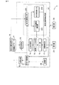
図1は、本実施形態に係る超音波診断装置1のブロック構成図を示している。同図に示すように、本超音波診断装置1は、超音波プローブ11、送信回路12、受信回路13、信号処理部14、画像データ生成部15、メモリ部16、画像構成部17、器具位置情報取得部18、中央制御回路21、器具位置情報処理部22、表示部24、操作部25、記憶部28を具備している。
FIG. 1 shows a block diagram of an ultrasonic diagnostic apparatus 1 according to this embodiment. As shown in the figure, the ultrasonic diagnostic apparatus 1 includes an
超音波プローブ11は、送信回路12からの駆動信号に基づき所定のタイミングで超音波を発生し、被検体からの反射波を電気信号に変換する複数の圧電振動子、当該圧電振動子に設けられる整合層、当該圧電振動子から後方への超音波の伝播を防止するバッキング材等を有している。当該超音波プローブ11から被検体Pに超音波が送信されると、当該送信超音波は、体内組織の音響インピーダンスの不連続面で次々と反射され、エコー信号として超音波プローブ11に受信される。このエコー信号の振幅は、反射することになった反射することになった不連続面における音響インピーダンスの差に依存する。また、送信された超音波パルスが、移動している血流や心臓壁等の表面で反射された場合のエコーは、ドプラ効果により移動体の超音波送信方向の速度成分を依存して、周波数偏移を受ける。
The
送信回路12は、図示しないトリガ発生回路、遅延回路およびパルサ回路等を有している。パルサ回路では、所定のレート周波数fr Hz(周期;1/fr秒)で、送信超音波を形成するためのレートパルスが繰り返し発生される。また、遅延回路では、チャンネル毎に超音波をビーム状に集束し且つ送信指向性を決定するのに必要な遅延時間が、各レートパルスに与えられる。トリガ発生回路は、このレートパルスに基づくタイミングで、プローブ11に駆動パルスを印加する。なお、送信回路12は、中央制御回路14の指示に従って所定のスキャンシーケンスを実行するために、超音波送信範囲、RPF(パルス繰り返し周波数)等を瞬時に変更可能な機能を有している。
The
受信回路13は、図示していないアンプ回路、A/D変換器、加算器等を有している。アンプ回路では、プローブ11を介して取り込まれたエコー信号をチャンネル毎に増幅する。A/D変換器では、増幅されたエコー信号に対し受信指向性を決定するのに必要な遅延時間を与え、その後加算器において加算処理を行う。この加算により、エコー信号の受信指向性に応じた方向からの反射成分が強調され、受信指向性と送信指向性とにより超音波送受信の総合的なビームが形成される。
The
信号処理部14は、Bモード処理ユニットとドプラ処理ユニットとを有している。Bモード処理ユニットは、受信回路13からエコー信号を受け取り、対数増幅、包絡線検波処理などを施し、信号強度が輝度の明るさで表現されるデータを生成する。ドプラ処理ユニットは、受信回路13から受け取ったエコー信号から速度情報を周波数解析し、ドプラ効果による血流や組織、造影剤エコー成分を抽出し、平均速度、分散、パワー等の血流情報を多点について求める。
The
画像データ生成部15は、ボリュームレンダリング演算のために必要な走査変換処理、例えばセクタ走査など非直交座標系のビーム走査で得たエコー情報を三次元直交座標系に座標変換、各ビーム間のデータ値のないボクセルに対してデータ補間等の走査変換処理を実行するDSC(デジタル・スキャン・コンバータ)である。この画像データ生成部15での走査変換処理により、超音波画像データが生成されることになる。 The image data generation unit 15 performs coordinate conversion of echo information obtained by scanning conversion processing necessary for volume rendering calculation, for example, beam scanning in a non-orthogonal coordinate system such as sector scanning into a three-dimensional orthogonal coordinate system, and data between each beam This is a DSC (digital scan converter) that performs scan conversion processing such as data interpolation on voxels having no value. Ultrasonic image data is generated by the scan conversion processing in the image data generation unit 15.
メモリ部16は、画像データ生成部15において実行された走査線変換処理後の画像データを記憶する。これにより、メモリ部16には、三次元ボリュームスキャンを実行した場合であれば、当該スキャンに対応した三次元データ取込領域の各ボクセルのエコー情報が記憶されることになる。なお、メモリ部16に記憶される情報は、例えば三次元データ取込領域の走査のたびに更新される。 The memory unit 16 stores the image data after the scanning line conversion process executed in the image data generation unit 15. Thus, if a three-dimensional volume scan is executed, the memory unit 16 stores echo information of each voxel in the three-dimensional data capture area corresponding to the scan. Note that the information stored in the memory unit 16 is updated each time the three-dimensional data capturing area is scanned, for example.
画像構成部17は、メモリ部16から予め設定される範囲に対応するデータを読み出し、ボリュームレンダリング処理、シェーディング処理等の各種画像処理を実行する。また、画像構成部17は、器具位置情報処理部22から受け取る位置情報と予め設定される診断対象の位置とに基づいて、超音波画像上における穿刺針及び診断対象のマーカ、及び穿刺針マーカと断対象マーカを結ぶ穿刺パスを所定の形態にて生成する。
The
器具位置情報取得部18は、超音波プローブ11に設けられた穿刺針アダプタに設けられており、被検体に刺入される器具(穿刺針)の位置情報を取得する。器具位置情報取得部18は、針刺入角度検出機能および針刺入長検出機能が備わっており、これから針の位置情報(すなわち、針刺入角度、針刺入長)を求めることができる。なお、本実施形態では、穿刺針の位置情報を取得するために当該器具位置情報取得部18を用いているが、これに拘泥されず、穿刺針アダプタ等に装着することなく磁気や光などを用いて位置情報を検出可能な位置センサ等を使用するようにしてもよい。
The instrument position
中央制御回路21は、情報処理装置(計算機)としての機能を持ち、本超音波診断装置本体の動作を制御する制御手段であり、記憶部28から画像生成・表示等を実行するための制御プログラムを読み出して自身が有するメモリ上に展開し、各種処理に関する演算・制御等を実行する。特に、中央制御回路21は、器具位置情報処理部22において得られた計算結果(後述)に基づいて、データ収集範囲(エコー信号を収集する範囲)、画像データ生成範囲(信号処理及びボリュームデータ生成の対象とする範囲)、表示範囲(超音波画像として表示する範囲)、パルス繰り返し周波数(PRF:Pulse Repetition Frequency)を制御する。
The
器具位置情報処理部22は、器具位置算出部220、データ収集範囲算出部221、表示範囲算出部222を有している。器具位置算出部220は、器具位置情報取得部18から得られた器具の位置情報をもとに、超音波画像中における穿刺針の位置(特に、先端の位置)を算出する。データ収集範囲算出部221は、算出された穿刺針の位置と予め設定される治療対象の位置とに基づいて、データ収集範囲を算出する。表示範囲算出部222は、算出された穿刺針の位置と予め設定される治療対象の位置とに基づいて、超音波画像による表示範囲を算出する。なお、データ収集範囲算出部221、表示範囲算出部222が行う計算は、例えば所定の計算式や、記憶部28に予め記憶されている位置情報−データ収集範囲テーブル、位置情報−表示範囲テーブルを用いて実行される。
The appliance position
なお、器具位置情報処理部22における計算結果は、中央制御回路21、画像構成部17に自動的に送り出される。
The calculation result in the appliance position
表示部24は、再構成部17から受け取った画像データを種々のパラメータの文字情報や目盛等と共に合成し、生体内の形態学的情報や、血流情報を画像として表示する。
The display unit 24 synthesizes the image data received from the
操作部25は、超音波診断装置1本体に接続され、オペレータからの各種指示、条件、関心領域(ROI)の設定指示、種々の画質条件設定指示等を装置本体にとりこむための各種スイッチ、ボタン、トラックボール、マウス、キーボード等を有している。例えば、操作者が操作部25の所定のボタンを操作することで、後述するフレームレート維持制御やこれによって得られる結果の所定形態による表示が実行される。 The operation unit 25 is connected to the main body of the ultrasonic diagnostic apparatus 1, and includes various switches and buttons for incorporating various instructions, conditions, region of interest (ROI) setting instructions, various image quality condition setting instructions, etc. from the operator into the apparatus main body. , Trackball, mouse, keyboard and so on. For example, when the operator operates a predetermined button of the operation unit 25, frame rate maintenance control described later and display of a result obtained thereby are performed in a predetermined form.
記憶部28は、取得された超音波画像データ、各種超音波送受信シーケンスを実現するためのプログラム等を記憶する。また、記憶部28は、後述するフレームレート維持制御機能を実現するための制御プログラムを記憶する。
The
(フレームレート維持制御機能)
次に、本超音波診断装置1が有する、フレームレート自動制御機能について説明する。この機能は、所定の基準に基づいて、穿刺針が十分に視認可能なように装置側がフレームレートを一定値以上に維持するものである。ここで、所定の基準とは、装置側が穿刺術治療の進行状況を把握可能な情報であり、例えば、穿刺針と診断対象との相対的な位置関係、穿刺針の刺入長、ワークフロー等に従う穿刺術治療の進行状況等を挙げることができる。
(Frame rate maintenance control function)
Next, the frame rate automatic control function of the ultrasonic diagnostic apparatus 1 will be described. This function is to maintain the frame rate at a certain value or more on the device side so that the puncture needle is sufficiently visible based on a predetermined standard. Here, the predetermined standard is information that allows the apparatus side to grasp the progress of the puncture treatment, and follows, for example, the relative positional relationship between the puncture needle and the diagnosis target, the insertion length of the puncture needle, the workflow, and the like. The progress of puncture treatment can be listed.
しかしながら、これらに拘泥することなく、例えば、術者のマニュアル操作に応答して、穿刺針が十分に視認可能なように装置側がフレームレートを制御するようにしてもよい。なお、以下においては、説明の便宜上、穿刺針と診断対象との相対的位置関係を基準とする場合を例とする。 However, without being bound by these, for example, in response to an operator's manual operation, the apparatus side may control the frame rate so that the puncture needle is sufficiently visible. In the following, for convenience of explanation, the case where the relative positional relationship between the puncture needle and the diagnosis target is used as a reference is taken as an example.
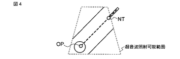
図2は、本フレームレート維持制御機能を説明するための概念図である。例えば同図に示す四角錐状の三次元領域が超音波照射(走査)可能範囲である場合、穿刺針Nと診断対象Oとの相対的位置(例えば、穿刺針先端NTと診断対象Oの目的部位OPとの間の距離)に応じて、データ収集範囲を同図に示す円筒領域TRに限縮することで装置における動作負荷を軽減させるものである。このデータ収集範囲の限縮は、器具位置情報処理部22によって算出されたデータ収集範囲を実現するように、例えば送信回路12において超音波送信の画角及び奥行き方向の距離(深さ)を制御し、且つ受信回路13における遅延時間を制御することでエコー信号受信範囲の奥行き方向の距離(深さ)を制御すればよい。
FIG. 2 is a conceptual diagram for explaining the present frame rate maintenance control function. For example, in the case where the quadrangular pyramid-shaped three-dimensional region shown in the figure is within a range where ultrasonic irradiation (scanning) is possible, the relative position between the puncture needle N and the diagnostic object O (for example, the purpose of the puncture needle tip NT and the diagnostic object O The operation load on the apparatus is reduced by limiting the data collection range to the cylindrical region TR shown in FIG. The limitation of the data collection range is, for example, controlling the angle of view of ultrasonic transmission and the distance (depth) in the depth direction in the
なお、図2の例では、穿刺針NTと診断対象Oの目的部位OPとの間の距離に応じて、穿刺パスPSを軸とする円筒領域TRをデータ収集範囲とする例を示している。しかしながら、これに拘泥されず、穿刺針先端NT、目的部位OP、穿刺パスPSを含み超音波照射可能範囲より狭い領域であれば、どの様なものであってもよい。 In the example of FIG. 2, an example is shown in which the cylindrical region TR with the puncture path PS as an axis is used as the data collection range according to the distance between the puncture needle NT and the target site OP of the diagnostic object O. However, the present invention is not limited to this, and any region may be used as long as the region includes the puncture needle tip NT, the target site OP, and the puncture path PS and is narrower than the ultrasonic irradiation possible range.
上記穿刺針Nと診断対象Oとの相対的位置に基づくデータ収集範囲の限縮により、一定以上深い領域や一定以上広い領域からの超音波反射を待つ必要がなくなり、超音波送走査に要する時間を短縮することができる。また、通常の超音波走査に比して、信号処理の対象となるデータサイズを小さくすることができる。従って、データ収集範囲の限縮前に比して装置における負荷を軽減させることができ、フレームレートを向上させることができる。 Due to the limitation of the data collection range based on the relative position between the puncture needle N and the diagnostic object O, there is no need to wait for ultrasonic reflection from a certain area deeper than a certain area or a certain area wider than a certain area, and the time required for ultrasonic transmission scanning Can be shortened. Further, the data size to be subjected to signal processing can be reduced as compared with normal ultrasonic scanning. Therefore, it is possible to reduce the load on the apparatus and to improve the frame rate as compared with before the limitation of the data collection range.
なお、本超音波新案装置がフレームレートを制御するための手法としては、上記データ収集範囲の限縮に拘泥されない。例えば次に述べる各手法、及びこれらの組み合わせを用いることも可能である。 Note that the method for controlling the frame rate by the ultrasonic model apparatus is not limited to the limitation of the data collection range. For example, the following methods and combinations thereof can be used.
第1の手法は、信号処理の対象とするエコー信号、及びボリュームデータ生成の対象とするエコー信号を制限するように、信号処理部14、画像データ生成部15を制御するものである。すなわち、受信したエコー信号のうちの一部を用いて信号処理を実行する、信号処理されたエコー信号のうちの一部を用いて画像データを生成する、又はこれらを適宜組み合わせることで、信号処理、画像データ生成における所用時間を限縮することができ、通常の超音波送受信に比してフレームレートを向上させることができる。
The first method is to control the
第2の手法は、ボリュームレンダリング処理等の対象とする画像データ(表示範囲)を制限するように、画像構成部17等を制御するものである。すなわち、生成されたボリュームデータのうちの一部を用いてボリュームレンダリング処理等を実行することで、画像処理における所用時間を限縮することができ、通常の三次元リアルタイム表示に比してフレームレートを向上させることができる。
The second method is to control the
第3の手法は、パルス繰り返し周波数(PRF)を上昇させるものである。すなわち、穿刺針と診断対象とを含む所定領域については好適な超音波送受信が実行されるように、それ以外の領域については、超音波受信前であっても次の超音波送信を実行するように、PRFを上昇させることで、通常の超音波送受信に比してフレームレートを向上させることができる。 The third method is to increase the pulse repetition frequency (PRF). That is, suitable ultrasonic transmission / reception is executed for a predetermined area including the puncture needle and the diagnosis target, and the next ultrasonic transmission is executed for other areas even before ultrasonic reception. In addition, by raising the PRF, the frame rate can be improved compared to normal ultrasonic transmission / reception.
なお、いずれの手法においても、穿刺針先端NT、目的部位OP、穿刺パスPSを含む領域を走査し、これらが映像化された超音波画像を生成する必要がある。また、構成としては、例えば操作部25に専用のインタフェースを設け、状況に応じていずれの手法又は組み合わせを用いるか選択可能とすることが好ましい。 In any method, it is necessary to scan an area including the puncture needle tip NT, the target site OP, and the puncture path PS and generate an ultrasound image in which these are visualized. As a configuration, for example, it is preferable that a dedicated interface is provided in the operation unit 25 so that it is possible to select which method or combination is used depending on the situation.
(動作)
次に、フレームレート自動制御機能を実行する場合における本超音波診断装置1の動作について説明する。以下の説明では、説明を具体的にするため、穿刺針Nと診断対象Oとの相対的位置に基づいてデータ収集範囲及び表示範囲の変更を行うことで、フレームレートを一定値以上に維持する場合を例とする。
(Operation)
Next, the operation of the ultrasonic diagnostic apparatus 1 when executing the frame rate automatic control function will be described. In the following description, the frame rate is maintained at a certain value or more by changing the data collection range and the display range based on the relative position between the puncture needle N and the diagnostic object O for specific explanation. Take the case as an example.
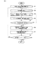
図3は、フレームレート自動制御機能を実行する場合において実行される各処理の流れを示したフローチャートである。同図に示すように、まず、体表(超音波プローブ11の位置)から目的部位までの距離を予め測定しておき、装置に入力する(ステップS1)。 FIG. 3 is a flowchart showing the flow of each process executed when the frame rate automatic control function is executed. As shown in the figure, first, the distance from the body surface (position of the ultrasonic probe 11) to the target site is measured in advance and input to the apparatus (step S1).
次に、穿刺針モニタリングが開始され、被検体に対して穿刺針が刺入されると、穿刺針先端NT、目的部位OP、穿刺パスPSが自動的にマーカ表示される。当該表示と並行して、器具位置情報取得部18によって当該穿刺針の位置情報が取得され、器具位置情報算出部220によって穿刺針の刺入角、刺入長が算出される(ステップS2、ステップS3)。
Next, puncture needle monitoring is started, and when the puncture needle is inserted into the subject, the puncture needle tip NT, the target site OP, and the puncture path PS are automatically displayed as markers. In parallel with the display, the instrument position
次に、データ収集範囲算出部221は、算出された穿刺針の刺入角、刺入長に基づいて、データ収集範囲を算出する。また、表示範囲算出部222は、算出された穿刺針の刺入角、刺入長に基づいて、表示範囲を算出する(ステップS4)。中央制御回路21は、算出されたデータ収集範囲及び表示範囲に基づいて現在のデータ収集範囲及び表示範囲を変更するか否かを判定し(ステップS5)、変更すると判定した場合には、算出されたデータ収集範囲に基づいて送信回路12、受信回路13を制御し、また、算出された表示範囲に基づいて画像構成部17を制御する(ステップS6、ステップS7)。一方、ステップS5においてデータ収集範囲及び表示範囲を変更しないと判定した場合には、ステップS2〜ステップS4の処理が繰り返し実行される。
Next, the data collection
次に、中央制御回路21は、器具位置情報取得部18による穿刺針の位置情報に基づいて穿刺針モニタリングを終了するか否かを判定し、例えば穿刺針が器具から取り外しされ位置情報の検出がなくなった場合等には、穿刺針モニタリングを終了する。一方、穿刺針モニタリングを継続すると判定した場合には、ステップS2〜ステップS7の処理が繰り返し実行される。
Next, the
以上述べたフレームレート自動制御機能を実行する場合における一連の動作により、術者は一定以上のフレームレートによって穿刺針をモニタリングすることができる。 The operator can monitor the puncture needle at a certain frame rate or higher by a series of operations in the case of executing the frame rate automatic control function described above.
ところで、上記図3に示した処理においては、例えば図4に示すような超音波画像が表示されている場合、ステップS6のデータ収集範囲変更、及びステップS7の表示範囲制御が実行された結果、例えば図5に示す超音波画像が表示部24に表示されることになる。従って、変更される表示範囲によっては、穿刺針のモニタリングに十分な大きさの超音波画像を確保することができない。 In the process shown in FIG. 3, for example, when an ultrasonic image as shown in FIG. 4 is displayed, the result of executing the data collection range change in step S6 and the display range control in step S7, For example, the ultrasonic image shown in FIG. 5 is displayed on the display unit 24. Therefore, depending on the display range to be changed, it is not possible to ensure an ultrasound image large enough for monitoring of the puncture needle.
そこで、本超音波診断装置では、上記フレームレート自動制御機能に合わせて、さらに表示される超音波画像の倍率制御及び画質制御を行うことも可能である。例えば、図4に示すような超音波画像が表示されている状態から表示範囲を限縮する場合には、図6に例示すように表示画像サイズを変更しないように、表示範囲の変更と共に表示画像の拡大率を制御する。また、画像を拡大することによる画質の低下を防止するように画像解像度を制御する。これにより、術者は、穿刺針Nと診断対象Oとを十分な大きさ及び画質でモニタリングすることができる。 Therefore, in this ultrasonic diagnostic apparatus, it is also possible to perform magnification control and image quality control of the displayed ultrasonic image in accordance with the automatic frame rate control function. For example, when the display range is limited from the state where the ultrasonic image as shown in FIG. 4 is displayed, the display image is displayed together with the change of the display range so as not to change the display image size as shown in FIG. Controls the magnification of the image. In addition, the image resolution is controlled so as to prevent deterioration in image quality due to enlargement of the image. Thereby, the surgeon can monitor the puncture needle N and the diagnostic object O with sufficient size and image quality.
以上述べた構成によれば、以下の効果を得ることができる。 According to the configuration described above, the following effects can be obtained.
本超音波診断装置によれば、所定の基準(例えば、穿刺術中における穿刺針と診断対象との相対的な位置関係)に基づいて、穿刺針が十分に視認可能なようにフレームレートを一定値以上に維持することができる。従って、三次元ボリュームボリュームスキャンによるリアルタイム表示等のフレームレートが問題になる場合であっても、穿刺針及び診断対象を好適なフレームレートによって映像化することができる。その結果、術者は、高いリアルタイム性を持って穿刺針及び診断対象を観察することができ、医療行為の質の向上に寄与することができる。 According to this ultrasonic diagnostic apparatus, the frame rate is set to a constant value so that the puncture needle is sufficiently visible based on a predetermined reference (for example, the relative positional relationship between the puncture needle and the diagnosis target during puncture). It can be maintained above. Therefore, even when the frame rate such as real-time display by three-dimensional volume volume scanning becomes a problem, the puncture needle and the diagnosis target can be imaged at a suitable frame rate. As a result, the surgeon can observe the puncture needle and the diagnostic object with high real-time characteristics, and can contribute to the improvement of the quality of medical practice.
また、本超音波診断装置によれば、フレームレートを一定値以上に維持するために、データ収集範囲、表示範囲、画像データ生成範囲等を単独で、或いは任意の組み合わせによって実現する。従って、術者は、状況に応じて好適な手法を選択することで、種々の状況に対応させることが可能となる。 Further, according to the present ultrasonic diagnostic apparatus, the data collection range, the display range, the image data generation range, and the like are realized singly or in any combination in order to maintain the frame rate above a certain value. Therefore, the surgeon can cope with various situations by selecting a suitable method according to the situation.
また、本超音波診断装置によれば、フレームレートを一定値以上に維持するための表示範囲限縮を行うと共に、画像の拡大及び画質の向上を実行する。従って、術者は、穿刺針及び診断対象を常に一定以上の大きさ及び画質で観察することができ、その結果医療行為の質の向上に寄与することができる。 In addition, according to the ultrasonic diagnostic apparatus, the display range is limited to maintain the frame rate at a certain value or more, and the image is enlarged and the image quality is improved. Therefore, the surgeon can always observe the puncture needle and the object to be diagnosed with a certain size and image quality, and as a result, can contribute to the improvement of the quality of medical practice.
なお、本発明は上記実施形態そのままに限定されるものではなく、実施段階ではその要旨を逸脱しない範囲で構成要素を変形して具体化できる。具体的な変形例としては、例えば次のようなものがある。 Note that the present invention is not limited to the above-described embodiment as it is, and can be embodied by modifying the constituent elements without departing from the scope of the invention in the implementation stage. Specific examples of modifications are as follows.
(1)本実施形態に係る各機能は、当該処理を実行するプログラムをワークステーション等のコンピュータにインストールし、これらをメモリ上で展開することによっても実現することができる。このとき、コンピュータに当該手法を実行させることのできるプログラムは、磁気ディスク(フロッピー(登録商標)ディスク、ハードディスクなど)、光ディスク(CD−ROM、DVDなど)、半導体メモリなどの記録媒体に格納して頒布することも可能である。 (1) Each function according to the present embodiment can also be realized by installing a program for executing the processing in a computer such as a workstation and developing the program on a memory. At this time, a program capable of causing the computer to execute the technique is stored in a recording medium such as a magnetic disk (floppy (registered trademark) disk, hard disk, etc.), an optical disk (CD-ROM, DVD, etc.), or a semiconductor memory. It can also be distributed.
(2)上記実施形態においては、図2に示したように三次元ボリュームスキャンを実行する場合におけるデータ収集範囲及び表示範囲の変更について説明した。しかしながら、これに拘泥されず、例えばドップラモード等に代表される二次元平面スキャンを実行する場合においても、同様な制御を行うようにしても同様の効果を得ることができる。 (2) In the above embodiment, the change of the data collection range and the display range in the case where the three-dimensional volume scan is executed as shown in FIG. 2 has been described. However, the present invention is not limited to this, and the same effect can be obtained even when a similar control is performed even when a two-dimensional plane scan represented by a Doppler mode or the like is executed.
また、上記実施形態に開示されている複数の構成要素の適宜な組み合わせにより、種々の発明を形成できる。例えば、実施形態に示される全構成要素から幾つかの構成要素を削除してもよい。さらに、異なる実施形態にわたる構成要素を適宜組み合わせてもよい。 In addition, various inventions can be formed by appropriately combining a plurality of components disclosed in the embodiment. For example, some components may be deleted from all the components shown in the embodiment. Furthermore, constituent elements over different embodiments may be appropriately combined.
以上本発明によれば、例えば穿刺治療や組織採取等の穿刺術において、穿刺針及び診断対象を十分に視認可能な超音波画像収集レートを常に維持することができる超音波診断装置及び超音波診断装置制御プログラムを実現することができる。 As described above, according to the present invention, for example, in puncture such as puncture treatment and tissue sampling, an ultrasonic diagnostic apparatus and an ultrasonic diagnosis that can always maintain an ultrasonic image collection rate at which a puncture needle and a diagnostic target can be sufficiently visually confirmed. A device control program can be realized.
1…超音波診断装置、11…超音波プローブ、12…送信回路、13…受信回路、14…信号処理部、15…画像生成部、16…メモリ部、17…画像構成部、18…器具位置情報取得部、21…中央制御回路、22…器具位置情報処理部、23…表示制御部、24…表示部、25…操作部、220…器具位置算出部、221…データ収集範囲算出部、222…表示範囲算出部 DESCRIPTION OF SYMBOLS 1 ... Ultrasound diagnostic apparatus, 11 ... Ultrasonic probe, 12 ... Transmission circuit, 13 ... Reception circuit, 14 ... Signal processing part, 15 ... Image generation part, 16 ... Memory part, 17 ... Image structure part, 18 ... Instrument position Information acquisition unit, 21 ... central control circuit, 22 ... instrument position information processing unit, 23 ... display control unit, 24 ... display unit, 25 ... operation unit, 220 ... instrument position calculation unit, 221 ... data collection range calculation unit, 222 ... Display range calculator
Claims (6)
前記超音波走査における前記複数の超音波振動子の超音波送信タイミング及び前記受信タイミング、及び前記超音波走査の繰り返し周期を制御する送受信手段と、
受信した前記エコー信号のうち予め設定される画像データ生成範囲に対応するエコー信号に基づいて、画像データを生成する画像データ生成手段と、
生成された画像データのうち、予め設定される表示範囲に対応する画像データに基づいて超音波画像を生成し表示する表示手段と、
前記被検体に刺入される穿刺針の刺入角及び刺入長を含む位置情報を取得する位置情報取得手段と、
前記超音波画像が所定のフレームレート以上で表示されるように、取得された前記位置情報と前記所定部位との位置関係に基づいて、前記データ収集範囲、前記繰り返し周期、前記画像データ生成範囲、前記表示範囲のうちの少なくとも一つを決定する決定手段と、
決定された前記データ収集範囲、前記繰り返し周期、前記画像データ生成範囲、前記表示範囲のうちの少なくとも一つに基づいて、前記送受信手段、前記画像データ生成手段、前記表示手段のうちの少なくともいずれかを制御する制御手段と、
を具備することを特徴とする超音波診断装置。 An ultrasonic probe comprising a plurality of ultrasonic transducers for ultrasonically scanning a subject in response to an applied drive signal and receiving echo signals from a preset data collection range;
Transmission / reception means for controlling the ultrasonic transmission timing and the reception timing of the plurality of ultrasonic transducers in the ultrasonic scanning, and the repetition period of the ultrasonic scanning;
Image data generating means for generating image data based on an echo signal corresponding to a preset image data generation range among the received echo signals;
Display means for generating and displaying an ultrasonic image based on image data corresponding to a preset display range among the generated image data;
Position information acquisition means for acquiring position information including an insertion angle and an insertion length of a puncture needle to be inserted into the subject;
Based on the positional relationship between the acquired position information and the predetermined part so that the ultrasonic image is displayed at a predetermined frame rate or higher, the data collection range, the repetition period, the image data generation range, Determining means for determining at least one of the display ranges;
Based on at least one of the determined data collection range, the repetition period, the image data generation range, and the display range, at least one of the transmission / reception means, the image data generation means, and the display means Control means for controlling
An ultrasonic diagnostic apparatus comprising:
前記決定手段は、前記テーブルに基づいて、前記データ収集範囲、前記繰り返し周期、前記画像データ生成範囲、前記表示範囲のうちの少なくともいずれかを決定すること、
を特徴とする請求項1記載の超音波診断装置。 The apparatus further includes a storage unit that stores a table that associates the positional relationship between the position information and the predetermined portion with at least one of the data collection range, the repetition period, the image data generation range, and the display range. ,
The determining means determines at least one of the data collection range, the repetition period, the image data generation range, and the display range based on the table;
The ultrasonic diagnostic apparatus according to claim 1.
を特徴とする請求項1記載の超音波診断装置。 The determining means determines at least one of the data collection range, the repetition period, the image data generation range, and the display range based on a predetermined calculation formula;
The ultrasonic diagnostic apparatus according to claim 1.
コンピュータに、
前記被検体を所定の周期で超音波走査し予め設定されるデータ収集範囲からのエコー信号を受信するように、前記超音波走査における超音波送信タイミング及び超音波受信タイミング、及び前記超音波走査の繰り返し周期を制御する送受信機能と、
受信した前記エコー信号のうち予め設定される画像データ生成範囲に対応するエコー信号に基づいて、画像データを生成する画像データ生成機能と、
生成された画像データのうち、予め設定される表示範囲に対応する画像データに基づいて超音波画像を生成し表示する表示機能と、
前記被検体に刺入される穿刺針の刺入角及び刺入長を含む位置情報を取得する位置情報取得機能と、
前記超音波画像が所定のフレームレート以上で表示されるように、取得された前記位置情報と前記所定部位との位置関係に基づいて、前記データ収集範囲、前記繰り返し周期、前記画像データ生成範囲、前記表示範囲のうちの少なくとも一つを決定する決定機能と、
決定された前記データ収集範囲、前記繰り返し周期、前記画像データ生成範囲、前記表示範囲のうちの少なくとも一つに基づいて、前記送受信機能、前記画像データ生成機能、前記表示機能のうちの少なくともいずれかにおける動作を制御する制御機能と、
を実現させることを特徴とする超音波診断装置制御プログラム。 A program for controlling an ultrasonic diagnostic apparatus for acquiring an ultrasonic image by ultrasonic scanning of a subject,
On the computer,
Ultrasonic transmission timing and ultrasonic reception timing in the ultrasonic scanning, and ultrasonic scanning so that the subject is ultrasonically scanned at a predetermined period and an echo signal is received from a preset data collection range. A transmission / reception function for controlling the repetition period;
An image data generation function for generating image data based on an echo signal corresponding to a preset image data generation range among the received echo signals;
A display function for generating and displaying an ultrasound image based on image data corresponding to a preset display range among the generated image data;
A position information acquisition function for acquiring position information including an insertion angle and an insertion length of a puncture needle inserted into the subject;
Based on the positional relationship between the acquired position information and the predetermined part so that the ultrasonic image is displayed at a predetermined frame rate or higher, the data collection range, the repetition period, the image data generation range, A determination function for determining at least one of the display ranges;
At least one of the transmission / reception function, the image data generation function, and the display function based on at least one of the determined data collection range, the repetition cycle, the image data generation range, and the display range A control function to control the operation in
An ultrasonic diagnostic apparatus control program characterized by realizing the above.
Priority Applications (1)
| Application Number | Priority Date | Filing Date | Title |
|---|---|---|---|
| JP2005142630A JP2006314689A (en) | 2005-05-16 | 2005-05-16 | Ultrasonic diagnostic system and its control program |
Applications Claiming Priority (1)
| Application Number | Priority Date | Filing Date | Title |
|---|---|---|---|
| JP2005142630A JP2006314689A (en) | 2005-05-16 | 2005-05-16 | Ultrasonic diagnostic system and its control program |
Publications (2)
| Publication Number | Publication Date |
|---|---|
| JP2006314689A true JP2006314689A (en) | 2006-11-24 |
| JP2006314689A5 JP2006314689A5 (en) | 2008-07-03 |
Family
ID=37535873
Family Applications (1)
| Application Number | Title | Priority Date | Filing Date |
|---|---|---|---|
| JP2005142630A Pending JP2006314689A (en) | 2005-05-16 | 2005-05-16 | Ultrasonic diagnostic system and its control program |
Country Status (1)
| Country | Link |
|---|---|
| JP (1) | JP2006314689A (en) |
Cited By (9)
| Publication number | Priority date | Publication date | Assignee | Title |
|---|---|---|---|---|
| JP2009118961A (en) * | 2007-11-13 | 2009-06-04 | Toshiba Corp | Ultrasonic diagnostic apparatus and ultrasonic diagnostic apparatus control program |
| JP2010017527A (en) * | 2008-06-09 | 2010-01-28 | Toshiba Corp | Ultrasonic diagnosing device |
| WO2010029888A1 (en) * | 2008-09-09 | 2010-03-18 | オリンパスメディカルシステムズ株式会社 | Ultrasound image display apparatus and ultrasound image display method |
| JP2010088486A (en) * | 2008-10-03 | 2010-04-22 | Toshiba Corp | Ultrasonic diagnostic apparatus |
| JP2010158294A (en) * | 2009-01-06 | 2010-07-22 | Toshiba Corp | Ultrasonic therapy assisting apparatus, and ultrasonic therapy supporting program |
| JP2013192627A (en) * | 2012-03-16 | 2013-09-30 | Konica Minolta Inc | Ultrasonic image diagnostic apparatus |
| WO2017051742A1 (en) * | 2015-09-25 | 2017-03-30 | オリンパス株式会社 | Ultrasonic observation device |
| CN109431584A (en) * | 2018-11-27 | 2019-03-08 | 深圳蓝韵医学影像有限公司 | The method and system of ultrasonic imaging |
| WO2021014926A1 (en) * | 2019-07-25 | 2021-01-28 | 富士フイルム株式会社 | Ultrasonic diagnosis device and control method for ultrasonic diagnosis device |
Citations (6)
| Publication number | Priority date | Publication date | Assignee | Title |
|---|---|---|---|---|
| JPH05269129A (en) * | 1992-03-25 | 1993-10-19 | Yokogawa Medical Syst Ltd | Ultrasonic diagnostic device |
| JPH08229042A (en) * | 1995-02-24 | 1996-09-10 | Fuji Photo Optical Co Ltd | Piercing ultrasonic probe |
| JPH1133021A (en) * | 1997-07-15 | 1999-02-09 | Fujitsu Ltd | Ultrasonograph |
| JPH1156851A (en) * | 1997-08-22 | 1999-03-02 | Fujitsu Ltd | Ultrasonograph and ultrasonic probe |
| JP2003190160A (en) * | 2001-12-11 | 2003-07-08 | Ge Medical Systems Global Technology Co Llc | Ultrasonic imaging system |
| JP2004230182A (en) * | 2004-03-31 | 2004-08-19 | Olympus Corp | Ultrasonograph |
-
2005
- 2005-05-16 JP JP2005142630A patent/JP2006314689A/en active Pending
Patent Citations (6)
| Publication number | Priority date | Publication date | Assignee | Title |
|---|---|---|---|---|
| JPH05269129A (en) * | 1992-03-25 | 1993-10-19 | Yokogawa Medical Syst Ltd | Ultrasonic diagnostic device |
| JPH08229042A (en) * | 1995-02-24 | 1996-09-10 | Fuji Photo Optical Co Ltd | Piercing ultrasonic probe |
| JPH1133021A (en) * | 1997-07-15 | 1999-02-09 | Fujitsu Ltd | Ultrasonograph |
| JPH1156851A (en) * | 1997-08-22 | 1999-03-02 | Fujitsu Ltd | Ultrasonograph and ultrasonic probe |
| JP2003190160A (en) * | 2001-12-11 | 2003-07-08 | Ge Medical Systems Global Technology Co Llc | Ultrasonic imaging system |
| JP2004230182A (en) * | 2004-03-31 | 2004-08-19 | Olympus Corp | Ultrasonograph |
Cited By (17)
| Publication number | Priority date | Publication date | Assignee | Title |
|---|---|---|---|---|
| JP2009118961A (en) * | 2007-11-13 | 2009-06-04 | Toshiba Corp | Ultrasonic diagnostic apparatus and ultrasonic diagnostic apparatus control program |
| JP2010017527A (en) * | 2008-06-09 | 2010-01-28 | Toshiba Corp | Ultrasonic diagnosing device |
| WO2010029888A1 (en) * | 2008-09-09 | 2010-03-18 | オリンパスメディカルシステムズ株式会社 | Ultrasound image display apparatus and ultrasound image display method |
| JP2010063549A (en) * | 2008-09-09 | 2010-03-25 | Olympus Medical Systems Corp | Ultrasonic image display apparatus |
| EP2322100A4 (en) * | 2008-09-09 | 2016-07-27 | Olympus Corp | Ultrasound image display apparatus and ultrasound image display method |
| JP2010088486A (en) * | 2008-10-03 | 2010-04-22 | Toshiba Corp | Ultrasonic diagnostic apparatus |
| JP2010158294A (en) * | 2009-01-06 | 2010-07-22 | Toshiba Corp | Ultrasonic therapy assisting apparatus, and ultrasonic therapy supporting program |
| JP2013192627A (en) * | 2012-03-16 | 2013-09-30 | Konica Minolta Inc | Ultrasonic image diagnostic apparatus |
| WO2017051742A1 (en) * | 2015-09-25 | 2017-03-30 | オリンパス株式会社 | Ultrasonic observation device |
| JP6157796B1 (en) * | 2015-09-25 | 2017-07-05 | オリンパス株式会社 | Ultrasonic observation equipment |
| CN108024793A (en) * | 2015-09-25 | 2018-05-11 | 奥林巴斯株式会社 | Ultrasound observation apparatus |
| CN108024793B (en) * | 2015-09-25 | 2020-11-17 | 奥林巴斯株式会社 | Ultrasonic observation device and method for operating ultrasonic observation device |
| CN109431584A (en) * | 2018-11-27 | 2019-03-08 | 深圳蓝韵医学影像有限公司 | The method and system of ultrasonic imaging |
| CN109431584B (en) * | 2018-11-27 | 2020-09-01 | 深圳蓝韵医学影像有限公司 | Method and system for ultrasonic imaging |
| WO2021014926A1 (en) * | 2019-07-25 | 2021-01-28 | 富士フイルム株式会社 | Ultrasonic diagnosis device and control method for ultrasonic diagnosis device |
| JP7313446B2 (en) | 2019-07-25 | 2023-07-24 | 富士フイルム株式会社 | ULTRASOUND DIAGNOSTIC SYSTEM AND CONTROL METHOD OF ULTRASOUND DIAGNOSTIC SYSTEM |
| US11759173B2 (en) | 2019-07-25 | 2023-09-19 | Fujifilm Corporation | Ultrasound diagnostic apparatus and control method of ultrasound diagnostic apparatus |
Similar Documents
| Publication | Publication Date | Title |
|---|---|---|
| US10278670B2 (en) | Ultrasound diagnostic apparatus and method of controlling ultrasound diagnostic apparatus | |
| JP5438985B2 (en) | Ultrasonic diagnostic apparatus and control program for ultrasonic diagnostic apparatus | |
| JP6176839B2 (en) | Ultrasonic diagnostic equipment | |
| JP7461530B2 (en) | Ultrasound diagnostic device and puncture support program | |
| JP6288996B2 (en) | Ultrasonic diagnostic apparatus and ultrasonic imaging program | |
| WO2007114375A1 (en) | Ultrasound diagnostic device and control method for ultrasound diagnostic device | |
| JP5165858B2 (en) | Ultrasonic diagnostic apparatus, ultrasonic image processing apparatus, and ultrasonic image processing program | |
| EP2253275A1 (en) | Ultrasonic diagnostic apparatus, ultrasonic image processing apparatus and ultrasonic image processing method | |
| JP2006314689A (en) | Ultrasonic diagnostic system and its control program | |
| US20150201906A1 (en) | Medical image diagnostic apparatus and medical image processing apparatus | |
| EP2402745B1 (en) | Ultrasound diagnosis apparatus, image processing apparatus and image processing method | |
| JP2011045708A (en) | Ultrasonograph, urtrasonic image processing device, ultrasonograph control program, and ultrasonic image processing program | |
| JP2007195867A (en) | Ultrasonic diagnostic equipment and ultrasonic image display program | |
| JP5274854B2 (en) | Ultrasonic diagnostic equipment | |
| JP5606025B2 (en) | Ultrasonic diagnostic apparatus, ultrasonic image processing apparatus, and ultrasonic image processing program | |
| JP5366372B2 (en) | Ultrasonic diagnostic apparatus and ultrasonic image data generation program | |
| JP4820565B2 (en) | Ultrasonic diagnostic equipment | |
| JP2012245092A (en) | Ultrasonic diagnostic apparatus | |
| JP2010220875A (en) | Ultrasonic diagnostic device, and control program therefor | |
| JP5142675B2 (en) | Ultrasonic diagnostic apparatus and ultrasonic diagnostic apparatus control program | |
| JP2015006260A (en) | Ultrasonic diagnostic apparatus | |
| JP5060141B2 (en) | Ultrasonic diagnostic equipment | |
| JP2007117566A (en) | Ultrasonic diagnostic equipment and control method for it | |
| JP2008220662A (en) | Ultrasonic diagnostic equipment and its control program | |
| JP5269430B2 (en) | Ultrasonic diagnostic equipment |
Legal Events
| Date | Code | Title | Description |
|---|---|---|---|
| A521 | Written amendment |
Free format text: JAPANESE INTERMEDIATE CODE: A523 Effective date: 20080515 |
|
| A621 | Written request for application examination |
Free format text: JAPANESE INTERMEDIATE CODE: A621 Effective date: 20080515 |
|
| A977 | Report on retrieval |
Free format text: JAPANESE INTERMEDIATE CODE: A971007 Effective date: 20110301 |
|
| A131 | Notification of reasons for refusal |
Free format text: JAPANESE INTERMEDIATE CODE: A131 Effective date: 20110315 |
|
| A521 | Written amendment |
Free format text: JAPANESE INTERMEDIATE CODE: A523 Effective date: 20110516 |
|
| A131 | Notification of reasons for refusal |
Free format text: JAPANESE INTERMEDIATE CODE: A131 Effective date: 20110830 |
|
| A521 | Written amendment |
Free format text: JAPANESE INTERMEDIATE CODE: A523 Effective date: 20111031 |
|
| A02 | Decision of refusal |
Free format text: JAPANESE INTERMEDIATE CODE: A02 Effective date: 20120313 |