JP4599208B2 - Ultrasonic diagnostic equipment - Google Patents
Ultrasonic diagnostic equipment Download PDFInfo
- Publication number
- JP4599208B2 JP4599208B2 JP2005105188A JP2005105188A JP4599208B2 JP 4599208 B2 JP4599208 B2 JP 4599208B2 JP 2005105188 A JP2005105188 A JP 2005105188A JP 2005105188 A JP2005105188 A JP 2005105188A JP 4599208 B2 JP4599208 B2 JP 4599208B2
- Authority
- JP
- Japan
- Prior art keywords
- transmission
- delay time
- drive signal
- reception
- unit
- Prior art date
- Legal status (The legal status is an assumption and is not a legal conclusion. Google has not performed a legal analysis and makes no representation as to the accuracy of the status listed.)
- Expired - Fee Related
Links
Images


Landscapes
- Ultra Sonic Daignosis Equipment (AREA)
Description
本発明は、超音波診断装置に係り、特に、複数個の超音波振動素子が配列された超音波プローブを用いて画像データの生成を行なう超音波診断装置に関する。 The present invention relates to an ultrasonic diagnostic apparatus, and more particularly to an ultrasonic diagnostic apparatus that generates image data using an ultrasonic probe in which a plurality of ultrasonic vibration elements are arranged.
超音波診断装置は、超音波プローブに内蔵された超音波振動素子(以下、振動素子と呼ぶ。)から発生する超音波を被検体内に放射し、被検体組織の音響インピーダンスの差異によって生ずる反射波を前記振動素子によって受信して画像データ等の生成と表示を行なうものである。このような超音波診断装置を用いた診断法は、超音波プローブを被検体の体表に接触させるだけの簡単な操作でリアルタイムの画像データが容易に得られるため、臓器の機能診断や形態診断に広く用いられている。 The ultrasonic diagnostic apparatus radiates an ultrasonic wave generated from an ultrasonic vibration element (hereinafter referred to as a vibration element) incorporated in an ultrasonic probe into a subject, and a reflection caused by a difference in acoustic impedance of the subject tissue. A wave is received by the vibration element to generate and display image data and the like. In such a diagnostic method using an ultrasonic diagnostic apparatus, real-time image data can be easily obtained by a simple operation by simply bringing an ultrasonic probe into contact with the body surface of a subject. Widely used in
被検体の組織あるいは血球からの反射波により生体情報を得る超音波診断法は、超音波パルス反射法と超音波ドプラ法の2つの大きな技術開発により急速な進歩を遂げ、上記技術を用いて得られるBモード画像とカラードプラ画像は、今日の超音波診断において不可欠なものとなっている。 Ultrasound diagnostic methods for obtaining biological information from reflected waves from the tissue or blood cells of a subject have made rapid progress with the development of two major technologies, the ultrasonic pulse reflection method and the ultrasonic Doppler method, and are obtained using the above technology. The B-mode image and the color Doppler image that are obtained are indispensable in today's ultrasound diagnosis.
又、近年、組織ハーモニックイメージング(Tissue Harmonic Imaging)法(以下、THI法と呼ぶ)なる新しい画像化技術が開発され、臨床の場で広く普及している。このイメージング法は、被検体の組織において生ずる超音波非線形現象を有効に利用した方法であり、例えば、中心周波数f0の超音波パルスを被検体内に放射した場合、被検体組織の非線型現象によって新たに発生する中心周波数2f0の高調波成分(THI成分)を選択的に受信して画像化を行なう。 In recent years, a new imaging technique called a tissue harmonic imaging method (hereinafter referred to as THI method) has been developed and widely used in clinical settings. This imaging method is a method that effectively uses an ultrasonic nonlinear phenomenon that occurs in the tissue of the subject. For example, when an ultrasonic pulse having a center frequency f0 is radiated into the subject, the imaging method is caused by a nonlinear phenomenon in the subject tissue. The newly generated harmonic component (THI component) of the center frequency 2f0 is selectively received and imaged.
この高調波成分は、被検体に放射された中心周波数f0の基本波成分に対して新たに発生するものであり、被検体組織の性状や反射部位までの伝搬距離、あるいは反射部位における超音波強度等に依存する。そして、従来の超音波画像におけるアーチファクトの主要因であった超音波プローブ及び臓器境界面の間で発生する多重反射波やサイドローブの受信感度を基本波成分に対して相対的に低減させることができるため、この高調波成分を用いたTHI法によりアーチファクトの少ない鮮明な画像データを得ることが可能となる。(例えば、特許文献1参照。)。 This harmonic component is newly generated with respect to the fundamental wave component of the center frequency f0 radiated to the subject. The property of the subject tissue, the propagation distance to the reflection site, or the ultrasonic intensity at the reflection site. Depends on etc. In addition, it is possible to reduce the reception sensitivity of multiple reflected waves and side lobes generated between the ultrasonic probe and the organ boundary surface, which is the main cause of the artifact in the conventional ultrasonic image, relative to the fundamental wave component. Therefore, clear image data with few artifacts can be obtained by the THI method using this harmonic component. (For example, refer to Patent Document 1).
このTHI法においては、当初、従来の超音波診断装置において使用されてきた駆動回路(パルサ回路)と同じ駆動回路が使用されていた。図14は、従来の駆動回路を示したものであり、高圧電源VccからコンデンサC0に充電された電荷をトランジスタ等で構成された電子スイッチSW0によって所定タイミングで放電することにより駆動信号が形成される。この場合、電子スイッチSW0の入力端子には矩形信号A0が供給され、この矩形信号A0によって導通状態になった電子スイッチSW1を介して放電された電荷はコンデンサC0とインダクタンスL0で構成された共振回路にて共振して駆動信号B0が形成される。 In the THI method, the same drive circuit as the drive circuit (pulsar circuit) that has been used in the conventional ultrasonic diagnostic apparatus was used at first. FIG. 14 shows a conventional drive circuit. A drive signal is formed by discharging the charge charged in the capacitor C0 from the high-voltage power supply Vcc at a predetermined timing by the electronic switch SW0 composed of a transistor or the like. . In this case, a rectangular signal A0 is supplied to the input terminal of the electronic switch SW0, and the electric charge discharged through the electronic switch SW1 rendered conductive by the rectangular signal A0 is a resonance circuit composed of a capacitor C0 and an inductance L0. The drive signal B0 is formed by resonance.
このような駆動信号を用いてTHI法を行なった場合、上述の駆動信号には、多くの高調波成分が含まれており、従って、被検体から得られる受信信号の中には駆動信号の高調波成分に対応した受信信号と、組織の非線型現象によって発生した高調波成分(THI成分)の受信信号が混在する。このため、THI法によって生成された画像データにおいて駆動信号の高調波成分に起因した受信信号が雑音成分として表示され、画質劣化の原因となっていた。 When the THI method is performed using such a drive signal, the above-described drive signal includes many harmonic components, and therefore, the received signal obtained from the subject has higher harmonics of the drive signal. The reception signal corresponding to the wave component and the reception signal of the harmonic component (THI component) generated by the tissue nonlinear phenomenon are mixed. For this reason, in the image data generated by the THI method, the received signal resulting from the harmonic component of the drive signal is displayed as a noise component, causing image quality degradation.
このような駆動信号の高調波成分による影響を排除する1つの方法として、例えば、極性の異なる駆動信号を用いて同一方向に対する超音波送受信を2回繰り返して行ない、夫々の超音波送受信において得られた受信信号を減算処理することにより組織の非線型現象によって発生した高調波成分(THI成分)のみを抽出する、所謂、パルスインバージョン法が開発されている(例えば、特許文献2参照。)。 As one method of eliminating the influence of the harmonic component of the drive signal, for example, ultrasonic transmission / reception in the same direction is repeated twice using drive signals having different polarities, and the ultrasonic signal is obtained in each ultrasonic transmission / reception. A so-called pulse inversion method has been developed in which only the harmonic components (THI components) generated by the nonlinear phenomenon of the tissue are extracted by subtracting the received signal (see, for example, Patent Document 2).
又、高調波成分の少ない駆動信号を生成する方法として、図14に示した駆動回路の代わりに、例えば、ガウス関数のような高調波成分の少ない包絡線関数を有した駆動信号を生成する方法も提案されている(例えば、特許文献3参照。)。 Further, as a method for generating a drive signal with less harmonic components, for example, a method for generating a drive signal having an envelope function with less harmonic components such as a Gaussian function instead of the drive circuit shown in FIG. Has also been proposed (see, for example, Patent Document 3).
一方、今日、最も普及している電子走査方式の超音波診断装置では、一般に複数個の振動素子を一次元に配列し、これらの振動素子の夫々に対する駆動タイミングを高速制御することによって2次元画像データのリアルタイム表示を行なっている。この場合、上述の2次元画像データは、被検体に対する2次元走査によって生成されるが、近年では、3次元的な走査を行なってボリュームデータを生成し、このボリュームデータを用いて任意断面の2次元画像データ(MPR画像データ)やボリュームレンダリング画像データ等の3次元画像データを生成する方法が検討されている。 On the other hand, in the most popular electronic scanning ultrasonic diagnostic apparatus today, a plurality of vibration elements are generally arranged in a one-dimensional manner, and a driving timing for each of these vibration elements is controlled at a high speed to obtain a two-dimensional image. Real-time display of data. In this case, the above-described two-dimensional image data is generated by two-dimensional scanning of the subject. However, in recent years, three-dimensional scanning is performed to generate volume data. Methods for generating three-dimensional image data such as three-dimensional image data (MPR image data) and volume rendering image data are being studied.
上述のボリュームデータの収集を行なう方法として、振動素子が1次元配列された従来の超音波プローブを更に機械的に移動あるいは回転させる方法と、2次元配列された振動素子を用い3次元空間の複数方向に対して超音波送受信を順次行なう方法が提案されているが、特に後者の方法は、短時間でボリュームデータの収集が可能なため、心臓などの動きの速い臓器に適した方法として注目されている。 As a method of collecting the volume data described above, a conventional ultrasonic probe in which vibration elements are one-dimensionally arranged is further moved or rotated mechanically, and a plurality of three-dimensional spaces using two-dimensionally arranged vibration elements are used. A method of sequentially transmitting and receiving ultrasonic waves with respect to the direction has been proposed. In particular, the latter method is attracting attention as a method suitable for fast-moving organs such as the heart because volume data can be collected in a short time. ing.
2次元配列された振動素子を用いる方法として、振動素子の各々に供給する駆動信号やこれらの振動素子から得られる受信信号の遅延時間制御によって3次元空間の任意の方向(角度)に対する超音波送受信を行なう方法と、例えば、所定方向(X方向)においては上述の遅延時間制御による超音波走査を行ない、前記所定方向に対して垂直な方向(Y方向)においては電子的な開口移動(送受信に使用する振動素子群の移動)による超音波走査を行なう方法がある。 As a method using two-dimensionally arranged vibration elements, ultrasonic transmission / reception with respect to an arbitrary direction (angle) in a three-dimensional space is performed by controlling a delay time of a drive signal supplied to each of the vibration elements and a reception signal obtained from these vibration elements. In the predetermined direction (X direction), for example, ultrasonic scanning based on the delay time control described above is performed, and in the direction perpendicular to the predetermined direction (Y direction), electronic aperture movement (for transmission and reception) is performed. There is a method of performing ultrasonic scanning by movement of a vibration element group to be used.
しかしながら、超音波プローブに配列された複数の振動素子と超音波診断装置本体に設けられた複数チャンネルの送受信回路を複数チャンネルのケーブルによって接続する構成の従来の超音波診断装置においては、上述のいずれの超音波走査方法においても振動素子数の増大(例えば、10倍〜100倍)に伴って、送受信回路やケーブルのチャンネル数も増大する。特に、ケーブルにおけるチャンネル数の増大によって操作者による超音波プローブの移動が妨げられ、その操作性を著しく低下させる。 However, in a conventional ultrasonic diagnostic apparatus having a configuration in which a plurality of vibration elements arranged in an ultrasonic probe and a plurality of channel transmission / reception circuits provided in the ultrasonic diagnostic apparatus main body are connected by a plurality of channels of cables, In this ultrasonic scanning method, the number of transmission / reception circuits and cable channels increases as the number of vibrating elements increases (for example, 10 to 100 times). In particular, the increase in the number of channels in the cable hinders the movement of the ultrasonic probe by the operator, and the operability thereof is significantly reduced.
このような問題点を解決するために、超音波プローブの内部に振動素子に対応した複数チャンネルの送信回路及び受信回路を内蔵する方法が検討されている。
2次元配列された振動素子を用いてTHI法を行なう場合、超音波プローブの操作性を考慮すれば許容される大きさや重さに上限があるため、各チャンネルの駆動回路規模は極力小さくする必要があり、従って、特許文献3に記載されているような複雑な駆動回路を超音波プローブに内蔵された送信部の各チャンネルに設けることはできない。
When performing the THI method using two-dimensionally arranged vibration elements, there is an upper limit on the allowable size and weight in consideration of the operability of the ultrasonic probe, so the drive circuit scale of each channel needs to be as small as possible. Therefore, a complicated driving circuit as described in
又、特許文献2に記載されたパルスインバージョン法は、フレーム周波数(単位時間に表示される画像データ枚数)が低下するため、高い時間分解能が要求される循環器領域の診断等に適用することは困難となる。
In addition, the pulse inversion method described in
本発明は、上述の問題点に鑑みてなされたものであり、その目的は、複数個の振動素子を有した超音波プローブを使用して画像データを生成する際に、超音波プローブの操作性を損なうことなく任意の包絡線波形を有した駆動信号の生成が可能な送信手段を前記超音波プローブに設けることにより良質な画像データの生成が可能な超音波診断装置を提供することにある。 The present invention has been made in view of the above-described problems, and an object of the present invention is to operate an ultrasonic probe when generating image data using an ultrasonic probe having a plurality of vibration elements. It is an object of the present invention to provide an ultrasonic diagnostic apparatus capable of generating high-quality image data by providing a transmission means capable of generating a drive signal having an arbitrary envelope waveform without damaging the waveform.
上記課題を解決するために、請求項1に係る本発明の超音波診断装置は、配列された複数の振動素子を備えた超音波プローブと、前記複数の振動素子の各々に対し第1の送信遅延時間を有した駆動信号を生成する複数チャンネルの駆動信号生成手段と、前記駆動信号の包絡線を形成するために第2の送信遅延時間を有した包絡線波形を生成する包絡線波形生成手段と、被検体の所定方向に超音波送信を行なうための前記第1の送信遅延時間及び前記第2の送信遅延時間を設定する遅延時間設定手段と、前記第1の送信遅延時間の大きさに基づいて前記駆動信号生成手段を共通接続して複数の駆動信号生成手段群を形成し、これらの駆動信号生成手段群の各々に対して前記包絡線波形を供給する共通接続手段と、前記振動素子によって得られた前記被検体からの超音波反射波に基づく受信信号を整相加算処理する受信手段と、この受信手段によって得られた整相加算信号に基づいて画像データを生成する画像データ生成手段を備え、前記駆動信号生成手段は、前記共通接続手段を介して前記包絡線波形生成手段から供給された包絡線波形と前記第1の送信用遅延時間に基づいて前記駆動信号を生成することを特徴としている。 In order to solve the above-described problem, an ultrasonic diagnostic apparatus according to a first aspect of the present invention includes an ultrasonic probe including a plurality of arranged vibration elements, and a first transmission to each of the plurality of vibration elements. A plurality of channels of driving signal generating means for generating a driving signal having a delay time; and an envelope waveform generating means for generating an envelope waveform having a second transmission delay time in order to form an envelope of the driving signal. Delay time setting means for setting the first transmission delay time and the second transmission delay time for performing ultrasonic transmission in a predetermined direction of the subject, and the magnitude of the first transmission delay time. Based on the common connection means for connecting the drive signal generation means in common to form a plurality of drive signal generation means groups, and supplying the envelope waveform to each of these drive signal generation means groups, and the vibration element Obtained by A receiving means for performing a phasing addition process on a reception signal based on an ultrasonic reflected wave from the subject, and an image data generating means for generating image data based on the phasing addition signal obtained by the receiving means, The drive signal generation means generates the drive signal based on the envelope waveform supplied from the envelope waveform generation means via the common connection means and the first transmission delay time.
又、請求項2に係る本発明の超音波診断装置は、配列された複数の振動素子とこれらの振動素子に対して送受信を行なうための第1の送受信手段を有した超音波プローブと、複数チャンネルのケーブルを介して前記第1の送受信手段と接続された第2の送受信手段と、被検体の所定方向に超音波送信を行なうために前記振動素子に供給する駆動信号の送信遅延時間を設定する遅延時間設定手段を備えた超音波診断装置において、前記第2の送受信手段は、前記駆動信号の包絡線を形成するために前記遅延時間設定手段が設定した第2の送信遅延時間を有した包絡線波形を生成する包絡線波形生成手段を備え、前記第1の送受信手段は、前記遅延時間設定手段が設定した第1の送信遅延時間を有した駆動信号を生成し前記振動素子に供給する複数チャンネルの駆動信号生成手段と、前記第1の送信遅延時間の大きさに基づいて前記駆動信号生成手段を共通接続して複数の駆動信号生成手段群を形成し、これらの駆動信号生成手段群の各々に対して前記包絡線波形生成手段が生成した包絡線波形を供給する共通接続手段を備え、前記駆動信号生成手段は、前記共通接続手段を介して前記包絡線波形生成手段から供給された包絡線波形と前記第1の送信用遅延時間に基づいて前記駆動信号を生成することを特徴としている。 According to a second aspect of the present invention, there is provided an ultrasonic diagnostic apparatus according to the present invention, an ultrasonic probe having a plurality of arranged vibration elements and a first transmission / reception means for performing transmission / reception with respect to these vibration elements; Second transmission / reception means connected to the first transmission / reception means via a channel cable and a transmission delay time of a drive signal supplied to the vibration element to perform ultrasonic transmission in a predetermined direction of the subject In the ultrasonic diagnostic apparatus including the delay time setting means, the second transmission / reception means has a second transmission delay time set by the delay time setting means to form an envelope of the drive signal. An envelope waveform generating unit configured to generate an envelope waveform, wherein the first transmitting / receiving unit generates a drive signal having a first transmission delay time set by the delay time setting unit and supplies the drive signal to the vibration element; Duplicate A plurality of drive signal generation units are formed by commonly connecting the drive signal generation units of the channel and the drive signal generation units based on the magnitude of the first transmission delay time. Common connection means for supplying an envelope waveform generated by the envelope waveform generation means to each of the envelopes, and the drive signal generation means is an envelope supplied from the envelope waveform generation means via the common connection means The drive signal is generated based on a line waveform and the first transmission delay time.
本発明によれば、複数個の振動素子を有した超音波プローブを使用して画像データを生成する際に、超音波プローブの操作性を損なうことなく任意の包絡線波形を有した駆動信号の生成が可能な送信手段を前記超音波プローブに設けることにより良質な画像データの生成が可能となる。 According to the present invention, when image data is generated using an ultrasonic probe having a plurality of vibration elements, a drive signal having an arbitrary envelope waveform without impairing the operability of the ultrasonic probe. Providing transmission means capable of generation in the ultrasonic probe makes it possible to generate high-quality image data.
以下、図面を参照して本発明の実施例を説明する。 Embodiments of the present invention will be described below with reference to the drawings.
以下に述べる本実施例では、超音波プローブ内に2次元配列されたM1個の振動素子の各々を所定の送信遅延時間を有した駆動信号で駆動して被検体の所定方向に対し送信超音波を放射する際、前記駆動信号の包絡線遅延を設定するM0チャンネル(M0<M1)の送信部を超音波診断装置本体に設け、前記駆動信号の位相遅延を設定するM1チャンネルの駆動信号生成部を、M0チャンネルの送受信信号用ケーブルを介して超音波診断装置本体と接続された超音波プローブに設ける。そして、前記ケーブルを介して前記送信部から供給された駆動信号の包絡線波形を、前記送信遅延時間の大きさに基づいて共通接続された複数個の前記駆動信号生成部に供給し、この駆動信号生成部において所望の送信遅延時間を有したM1チャンネルの駆動信号を生成する。 In the present embodiment described below, each of the M1 vibrating elements that are two-dimensionally arranged in the ultrasonic probe is driven by a drive signal having a predetermined transmission delay time to transmit ultrasonic waves in a predetermined direction of the subject. M0 channel (M0 <M1) transmission unit for setting the envelope delay of the drive signal when radiating the signal, and the M1 channel drive signal generation unit for setting the phase delay of the drive signal Are provided on the ultrasonic probe connected to the ultrasonic diagnostic apparatus main body via the transmission / reception signal cable of the M0 channel. Then, an envelope waveform of the drive signal supplied from the transmission unit via the cable is supplied to the plurality of drive signal generation units commonly connected based on the magnitude of the transmission delay time, and this drive The signal generation unit generates an M1 channel drive signal having a desired transmission delay time.
(装置の構成)
以下では、本発明の実施例における超音波診断装置の構成と各ユニットの動作につき図1乃至図11を用いて説明する。尚、図1は、本実施例における超音波診断装置の全体構成を示すブロック図であり、図7及び図9は、この超音波診断装置を構成する送受信部及びデータ生成部の構成を示すブロック図である。
(Device configuration)
Hereinafter, the configuration of the ultrasonic diagnostic apparatus and the operation of each unit according to the embodiment of the present invention will be described with reference to FIGS. FIG. 1 is a block diagram showing the overall configuration of the ultrasonic diagnostic apparatus according to the present embodiment, and FIGS. 7 and 9 are blocks showing the configurations of a transmission / reception unit and a data generation unit that constitute the ultrasonic diagnostic apparatus. FIG.
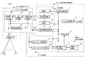
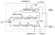
図1に示す超音波診断装置1000は、超音波プローブ200と、M0チャンネルから構成される送受信信号用のケーブル201及び制御信号用のケーブル202を介して前記超音波プローブ200と接続された超音波診断装置本体203から構成されている。
An ultrasonic
超音波プローブ200は、被検体の所定送受信方向に対して超音波の送受信を行なう2次元配列された複数個の振動素子1と、超音波診断装置本体203から供給された駆動信号の包絡線波形(以下では、包絡線波形と呼ぶ。)と送信遅延時間の設定値に基づいて前記振動素子1を駆動するための駆動信号を生成し、更に、振動素子1から得られた受信信号に対する第1の整相加算(所定の方向から得られた受信信号を位相合わせして加算)を行なうプローブ内送受信部(第1の送受信部)2を備えている。
The ultrasonic probe 200 includes a plurality of two-dimensionally arranged
一方、超音波診断装置本体203は、所定の遅延時間を有した前記包絡線波形の生成とプローブ内送受信部2における第1の整相加算によって得られた受信信号に対し第2の整相加算を行なう送受信部(第2の送受信部)3を備え、更に、送受信部3における第2の整相加算によって得られた受信信号を信号処理してBモードデータ及びカラードプラデータを生成するデータ生成部4と、複数の送受信方向の各々に対してデータ生成部4が生成した上記データを順次保存して2次元あるいは3次元のBモード画像データやカラードプラ画像データを生成し、更に、これらの画像データに対して所望の画像処理を行なう画像データ記憶・処理部5と、処理前あるいは処理後の画像データを表示する表示部6を備えている。
On the other hand, the ultrasonic diagnostic apparatus main body 203 generates a second phasing addition for the reception signal obtained by generating the envelope waveform having a predetermined delay time and the first phasing addition in the in-probe transmitting / receiving
又、超音波診断装置本体203は、送受信部3あるいはデータ生成部4に対して送信超音波の中心周波数とほぼ等しい周波数の連続波あるいは矩形波を発生する基準信号発生部7と、所定方向に対して超音波送受信を行なうために振動素子1に供給する駆動信号及び振動素子1から得られた受信信号に対して遅延時間を設定する遅延時間設定部8と、被検体情報の入力、装置の初期設定、更には各種コマンド信号の入力等を行なう入力部9と、超音波診断装置1000の各ユニットを統括的に制御するシステム制御部10を備えている。
The ultrasonic diagnostic apparatus main body 203 includes a reference
超音波プローブ200における振動素子1は、被検体の表面に対してその前面を接触させ超音波の送受信を行なうものであり、M1の振動素子1から構成されている。この振動素子1は電気音響変換素子であり、送信時には電気的な駆動信号を超音波パルス(送信超音波)に変換し、受信時には超音波反射波(受信超音波)を電気信号(受信信号)に変換する機能を有している。尚、以下では、説明を簡単にするために送信用振動素子数と受信用振動素子数は何れもM1とし、同一の振動素子を用いて送信超音波の送信と受信超音波の受信を行なう場合について述べるが、これに限定されない。
The
一方、プローブ内送受信部2は、M1チャンネルで構成される駆動信号生成部22及び整相加算部24と、共通接続部23と、送受信切り換え部25を有している。
On the other hand, the intra-probe transmission /
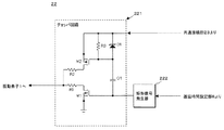
駆動信号生成部22の具体的な構成を図2に示す。この図2に示すように駆動信号生成部22は、チョッパ回路221と矩形信号発生器222を備えている。
A specific configuration of the
チョッパ回路221は、N型のFET素子M1とP型のFET素子M2の直列接続によって構成されており、FET素子M1の第1の端子とFET素子M2の第1の端子は抵抗R1及びR2を介して接続される。又、FET素子M1の第2の端子は接地され、FET素子M2の第2の端子には、後述する共通接続部23等を介して超音波診断装置本体203より包絡線波形が供給される。そして、FET素子M1及びM2の第3の端子(ゲート端子)は矩形信号発生器222の出力端子に接続され、所定の位相遅延を有した矩形信号が供給される。
The
一方、矩形信号発生器222は、超音波診断装置本体203の遅延時間設定部8からケーブル202を介して供給された送信遅延時間τtに対応した時刻を基準とし、送信超音波の周期T0と略等しい繰り返し周期を有する矩形信号を所定期間Tbの間発生する。そして、この矩形信号は、上述のFET素子M1及びM2のゲート端子に供給される。
On the other hand, the
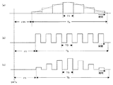
図3は、駆動信号生成部22における駆動信号の生成方法を示したものである。図3(a)は、ケーブル201、送受信切り換え部25及び共通接続部23を介して超音波診断装置本体203より供給されるガウス型の包絡線波形を示しており、この包絡線波形は、基準時刻t=Txに対し後述する送信用の基準遅延時間τtnだけ遅延して生成される。又、図3(b)は、前記基準時刻t=Txから送信遅延時間τtだけ遅延して矩形信号発生器222から出力される繰り返し周期T0の矩形信号、図3(c)は、チョッパ回路221から出力される駆動信号を示している。
FIG. 3 shows a drive signal generation method in the
即ち、チョッパ回路221は、矩形信号発生器222によって生成された矩形信号によって包絡線波形をスイッチングすることにより基準時刻t=Txに対して送信遅延時間τtだけ遅延したガウス型の駆動信号を生成する。但し、図3(b)に示した矩形信号の持続時間Tbは、通常、図3(a)における包絡線波形幅Taに略等しくなるように設定される。尚、図3(a)に示した包絡線波形の生成方法については後述する。
That is, the
図1に戻って、プローブ内送受信部2の共通接続部23は、M1チャンネルの駆動信号生成部22に対して超音波診断装置本体203の遅延時間設定部8が設定した送信遅延時間τt(τt(1)乃至τt(M1))と予め設定された基準遅延時間τtn(τtn(1)乃至τtn(M0))を比較する。そして、所定の基準遅延時間τtnとの遅延時間差Δτtが基準遅延時間間隔Δτtn以内となる送信遅延時間τtの駆動信号生成部22を共通接続してM0チャンネルの駆動信号生成部群にグルーピングする。そして、共通接続により形成された駆動信号生成部群の各々に対して基準遅延時間τtnを有する包絡線波形を超音波診断装置本体203より供給する。
Returning to FIG. 1, the
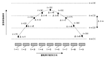
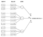
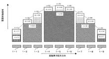
図4は、超音波診断装置本体203の遅延時間設定部8が設定した送信遅延時間τt及び基準遅延時間τtnとこれらの遅延時間に基づいて行なわれる共通接続を模式的に示したものであり、配列された振動素子1−1乃至1−M1を用い所定距離に対して送信超音波を収束する際に遅延時間設定部8が設定する送信遅延時間τt(1)乃至τt(M1)を示している。但し、この図では、説明を簡単にするためにM1=9及びM0=3として1列に配列した振動素子1−1乃至1−9について述べるが、実際には、2次元配列された振動素子1−1乃至1−M1に対し同様な共通接続を行なってM0チャンネルにグルーピングし、これらの各々に対し基準遅延時間τtn(1)乃至τtn(M0)を有したM0チャンネルの包絡線波形が供給される。
FIG. 4 schematically shows a transmission delay time τt and a reference delay time τtn set by the delay
即ち、プローブ内送受信部2の共通接続部23は、遅延時間設定部8が振動素子1−1乃至1−9に対応した駆動信号生成部22−1乃至22−9の各々に対して設定した送信遅延時間τt(1)乃至τt(9)と基準遅延時間間隔Δτtnで予め設定された基準遅延時間τtn(1)乃至τtn(3)を比較する。
That is, the
そして、例えば、基準遅延時間τtn(1)とτtn(2)の間にある送信遅延時間τt(1)及びτt(9)が設定された駆動信号生成部22−1及び22−9を共通接続し、超音波診断装置本体203の送受信部3より基準遅延時間τtn(1)を有した包絡線波形を供給する。同様にして、基準遅延時間τtn(2)とτtn(3)の間にある送信遅延時間τt(2)、τt(3)、τt(7)及びτt(8)が設定された駆動信号生成部22−2、22−3、22−7及び22−8、基準遅延時間τtn(3)とτtn(4)の間にある送信遅延時間τt(4)乃至τt(6)が設定された駆動信号生成部22−4乃至22−6を夫々共通接続し、前記送受信部3より基準遅延時間τtn(2)及びτtn(3)を有した包絡線波形を供給する。
For example, the drive signal generators 22-1 and 22-9 in which transmission delay times τt (1) and τt (9) between the reference delay times τtn (1) and τtn (2) are set are connected in common. Then, an envelope waveform having a reference delay time τtn (1) is supplied from the transmission /
再び図1に戻って、プローブ内送受信部2における整相加算部24は、図示しないチャンネル選択回路と遅延回路と加算器を備え、前記チャンネル選択回路は、例えば、振動素子1−1乃至1−M1に対して超音波診断装置本体203の遅延時間設定部8が設定した受信遅延時間τr(1)乃至τr(M1)とΔτrn間隔で設定された基準遅延時間τrn(1)乃至τrn(M0)の差を算出し、τrn(1)<τr≦τrn(2)、τrn(2)<τr≦τrn(3)、τrn(3)<τrに該当するチャンネルを選択する。次いで前記遅延回路は、選択されたチャンネルの受信信号に対し受信遅延時間τrと基準遅延時間τrnの時間差に基づいた遅延時間を与え、前記加算器は、前記遅延時間が与えられた受信信号を加算合成する。
Returning to FIG. 1 again, the phasing
次に、図5及び図6を用いて上述の整相加算部24における整相加算につき更に詳しく説明する。但し、この場合も図4の場合と同様にして振動素子1を1列に配列したM1=9及びM0=3の場合について述べるが、実際には、2次元配列された振動素子1−1乃至1−M1に対して同様な整相加算が行なわれてM0チャンネルにグルーピングされる。
Next, the phasing addition in the
図5は、配列された振動素子1−1乃至1−9に対して超音波診断装置本体203の遅延時間設定部8が設定した受信遅延時間τr(τr(1)乃至τr(9))を模式的に示したものであり、上述のチャンネル選択回路は、先ず、遅延時間設定部8が振動素子1−1乃至1−9の各々に対して設定した受信遅延時間τr(1)乃至τr(9)とΔτrn間隔で予め設定された基準遅延時間τrn(1)乃至τrn(3)を比較する。そして、例えば、基準遅延時間τrn(1)とτrn(2)の間にある受信遅延時間τr(1)及びτr(9)が設定された振動素子1−1及び1−9を選択する。
FIG. 5 shows the reception delay time τr (τr (1) to τr (9)) set by the delay
図6は、選択された振動素子1から得られる受信信号に対する整相加算の方法を示したものであり、例えば、前記遅延回路は、チャンネル選択回路によって選択された振動素子1−1の受信信号に対して遅延時間差Δτr(1)=τr(1)−τrn(1)を与え、同様にして、振動素子1−9の受信信号に対して遅延時間差Δτr(9)=τr(9)−τrn(1)を与える。そして、前記加算器は、上述の遅延時間差が与えられた受信信号を加算合成する。
FIG. 6 shows a method of phasing addition for the received signal obtained from the selected
又、チャンネル選択回路は、基準遅延時間τrn(2)とτrn(3)の間にある受信遅延時間τr(2)、τr(3)、τr(7)及びτr(8)が設定された振動素子1−2、1−3、1−7及び1−8を選択し、これらの振動素子1から得られた受信信号は、前記遅延回路にて遅延時間差Δτr(2)=τr(2)−τrn(2)、Δτr(3)=τr(3)−τrn(2)、Δτr(7)=τr(7)−τrn(2)及びΔτr(8)=τr(8)−τrn(2)が与えられた後加算器によって整相加算される。同様にして、基準遅延時間τrn3とτrn4の間にある受信遅延時間τr4乃至τr6が設定された振動素子1−4乃至1−6によって得られた受信信号に対して遅延時間差Δτr(4)=τr(4)−τrn(3)、Δτr(5)=τr(5)−τrn(3)及びΔτr(6)=τr(6)−τrn(3)が与えられ整相加算される。
In addition, the channel selection circuit is a vibration in which reception delay times τr (2), τr (3), τr (7) and τr (8) between the reference delay times τrn (2) and τrn (3) are set. Elements 1-2, 1-3, 1-7, and 1-8 are selected, and the received signal obtained from these
次に、図1のプローブ内送受信部2における送受信切り換え部25は、送受信において同一のケーブル201を共用する際に、超音波診断装置本体203にて生成された包絡線波形のプローブ内送受信部2への供給とプローブ内送受信部2における整相加算信号の超音波診断装置本体203への供給の切り換えを行なう。
Next, when the transmission /
一方、図7に示した送受信部3は、所定の基準遅延時間τtnを有した駆動信号の包絡線波形を生成する送信部31と、プローブ内送受信部2の整相加算部24における第1の整相加算によってM0チャンネルに纏められた受信信号に対し基準遅延時間τrnを与えて第2の整相加算を行なう受信部32と、ケーブル201に対し送信及び受信の切り換えを行なう送受信切り換え部33を備えている。
On the other hand, the transmission /
そして、送信部31は、レートパルス発生器311と、送信遅延回路312と、包絡線波形生成回路313を備え、レートパルス発生器311は、基準信号発生部7から供給される連続波を分周することによって送信超音波の繰り返し周期を決定するレートパルスを生成し、更に、このレートパルスに同期した所定期間Taにおいて繰り替えし周期T1の矩形信号を発生する。
The
又、送信遅延回路312は、M0チャンネルから構成され、送信において細いビーム幅を得るために所定の深さに送信超音波を収束するための遅延時間と所定の方向に送信超音波を放射するための遅延時間を前記矩形信号に与える。例えば、送信遅延回路312は、レートパルス発生器311から出力される矩形信号に対して図4に示した基準遅延時間τtn(τtn(1)乃至τtn(M0)を与える。
The
次に、包絡線波形生成回路313は、RAM(Random Access Memory)314と、D/A変換器315と、リニアドライバ316を備えている。そして、RAM314には、後述の入力部9にて設定あるいは選択された包絡線関数に対応した包絡線データがシステム制御部10から予め供給され、このRAM314に保存された包絡線データは送信遅延回路312から供給される基準遅延時間τtnを有した矩形信号によって読み出される。次いで、D/A変換器315は、RAM314から出力されたデジタル信号をD/A変換し、リニアドライバ316は、D/A変換によって形成された包絡線波形を好適な大きさに増幅する。
Next, the envelope
一方、送受信部3の受信部32は、プリアンプ321と、A/D変換器322と、ビームフォーマ323を備えている。プリアンプ321は、プローブ内送受信部2の整相加算部24から送受信切り換え部25、ケーブル201及び送受信部3の送受信切換え部33を介して供給されたM0チャンネルの受信信号を増幅して十分なS/Nを確保する。このプリアンプ321において所定の大きさに増幅された受信信号は、A/D変換器322にてデジタル信号に変換され、ビームフォーマ323に送られる。
On the other hand, the
ビームフォーマ323は、図示しない遅延回路と加算回路を有し、A/D変換器322においてデジタル信号に変換されたM0チャンネルの受信信号に対し、所定の深さからの超音波反射波を収束するための遅延時間と所定方向に対して受信指向性を設定するための遅延時間を与えた後加算合成(第2の整相加算)を行なう。この場合、ビームフォーマ323では、図5に示した基準遅延時間τrn(1)乃至τrn(M0)が前記M0チャンネルの受信信号に対して与えられる。
The beam former 323 includes a delay circuit and an adder circuit (not shown), and converges an ultrasonic reflected wave from a predetermined depth to the received signal of the M0 channel converted into a digital signal by the A /
一方、送受信切り換え部33は、送受信において同一のケーブル201を共用する際に、超音波診断装置本体203の送受信部3にて生成された包絡線波形の超音波プローブ200におけるプローブ内送受信部2への供給と前記プローブ内送受信部2における整相加算出力の前記送受信部3への供給の切り換えを行なう。
On the other hand, when the transmission /
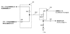
図8は、プローブ内送受信部2における送受信切り換え部25と送受信部3における送受信切り換え部33の具体例を示したものであり、送受信切り換え部25はダイオードD2及びD3によって構成することができる。この場合、超音波診断装置本体203における送信部31のリニアドライバ316からケーブル201を介して供給された正極性の包絡線波形によってダイオードD2は導通状態に、又、ダイオードD3は遮断状態となり、リニアドライバ316の駆動信号は送受信切り換え部33の電子スイッチSW1、ケーブル201及びダイオードD2を介してプローブ内送受信部2の共通接続部23に供給される。
FIG. 8 shows a specific example of the transmission /
一方、受信時においてケーブル201には電子スイッチSW1及び抵抗R3を介して負のバイアス電圧−Vcが印加され、このバイアス電圧−VcによってダイオードD2は遮断状態に、ダイオードD3は導通状態となる。そして、整相加算部24の出力信号はダイオードD3、ケーブル201及び電子スイッチSW1を介して受信部32のプリアンプ321に供給される。
On the other hand, a negative bias voltage −Vc is applied to the
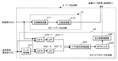
次に、図9に示したデータ生成部4は、上述の受信部32におけるビームフォーマ323から出力された受信信号を信号処理してBモードデータを生成するBモードデータ生成部41と、前記受信信号を信号処理してカラードプラデータを生成するカラードプラデータ生成部42を備え、Bモードデータ生成部41は、包絡線検波器411と対数変換器412を備えている。
Next, the
この包絡線検波器411は、送受信部3の受信部33におけるビームフォーマ323から出力された受信信号に対して包絡線検波を行ない、対数変換器412は、包絡線検波後の受信信号に対する対数変換処理によって小さな信号振幅を相対的に強調し送受信方向単位のBモードデータを生成する。
The
一方、カラードプラデータ生成部42は、π/2移相器421、ミキサ422−1及び422−2、LPF(低域通過フィルタ)423−1及び423−2を備えており、送受信部3の受信部32から供給された受信信号に対して直交位相検波を行なって複素信号(I信号とQ信号)を生成する。
On the other hand, the color Doppler
更に、カラードプラデータ生成部42は、ドプラ信号記憶回路424、MTIフィルタ425及び自己相関演算器426を備えている。そして、直交位相検波によって得られた複素信号は、ドプラ信号記憶回路424に一旦保存され、次いで、高域通過用のデジタルフィルタであるMTIフィルタ425は、ドプラ信号記憶回路424に保存された前記複素信号を読み出し、この複素信号に対して臓器の固定反射体あるいは臓器の呼吸性移動や拍動性移動などに起因するドプラ成分(クラッタ成分)の除去を行なう。
Further, the color Doppler
又、自己相関演算器426は、MTIフィルタ425によって抽出された血流情報のドプラ信号に対して自己相関値を算出し、更に、この自己相関値に基づいて血流の平均流速値、分散値、更にはパワー値等を算出してカラードプラデータを生成する。
Further, the
次に、図1に戻って、画像データ記憶・処理部5は、画像データ記憶部51と画像データ処理部52を備えており、画像データ記憶部51は、データ生成部4において送受信方向単位で生成されたBモードデータ及びカラードプラデータを順次保存して、3次元あるいは2次元のBモード画像データ及びカラードプラ画像データを生成する。
Next, returning to FIG. 1, the image data storage /
一方、画像データ処理部52は、画像データ記憶部51において生成された3次元のBモード画像データやカラードプラ画像データを用い、ボリュームレンダリング画像データ、サーフェイスレンダリング画像データ、MIP(Maximum Intensity Projection:最大値投影)画像データ、更には、MPR(Multi-Planar Reconstruction:断面変換)画像データ等を生成するための画像処理を行なう。
On the other hand, the image
次に、表示部6は、図示しない表示用データ生成回路と変換回路とモニタを備えており、画像データ記憶・処理部5において生成されたBモード画像データやカラードプラ画像データは前記表示用データ生成回路において所定の表示形態に対応した走査変換等の処理が行なわれて表示用データが生成され、この表示用データは、変換回路においてD/A変換とテレビフォーマット変換が行われモニタに表示される。
Next, the
一方、遅延時間設定部8は、超音波診断装置本体203のシステム制御部10から供給された送信超音波及び受信超音波の送受信方向や焦点距離の情報に基づき、振動素子1−1乃至1−M1に対する駆動信号の送信遅延時間τt(1)乃至τt(M1)と前記振動素子1−1乃至1−M1から得られたM1チャンネルの受信信号に対する受信遅延時間τr(1)乃至τr(M1)を設定する。そして、設定した上記送信遅延時間τt(1)乃至τt(M1)をプローブ内送受信部2の駆動信号生成部22及び共通接続部23に、又、受信遅延時間τr(1)乃至τr(M1)をプローブ内送受信部2の整相加算部24に供給する。
On the other hand, the delay
更に、遅延時間設定部8は、入力部9にて設定された基準遅延時間間隔Δτtn及び基準遅延時間間隔Δτrnに基づいて送信時の基準遅延時間τtn(1)乃至τtn(M0)及び受信時の基準遅延時間τrn(1)乃至τrn(M0)を設定する。そして、設定した基準遅延時間τtn(1)乃至τtn(M0)をプローブ内送受信部2の共通接続部23と超音波診断装置本体203の送信部31における送信遅延回路312に、又、基準遅延時間τrn(1)乃至τrn(M0)をプローブ内送受信部2の整相加算部24と超音波診断装置本体203の受信部32におけるビームフォーマ323に供給する。
Further, the delay
又、入力部9は、操作パネル上に表示パネルやキーボード、トラックボール、マウス、選択ボタン、入力ボタン等の入力デバイスを備え、患者情報の入力、データ収集条件及び表示条件等の設定、駆動信号における包絡線関数の設定あるいは選択、送信及び受信における基準遅延時間間隔Δτtn及びΔτrnの設定、更には、種々コマンド信号の入力等を行なう。
The
そして、システム制御部10は、図示しないCPUと記憶回路を備え、操作者によって入力部9から入力あるいは設定された上述の各種情報は前記記憶回路に保存される。又、この記憶回路には駆動波形の包絡線データが複数種類保存されている。そして、前記CPUは、これらの情報に基づいて、プローブ内送受信部2、送受信部3、データ生成部4をはじめとする上述の各ユニットの制御やシステム全体の制御を統括して行なう。
The
(画像データの生成手順)
次に、本実施例における画像データの生成手順について説明する。操作者は、先ず入力部9にて患者情報の入力を行ない、更に、画像データの収集モードを選択する。尚、ここでは、収集モードとして3次元セクタ走査による3次元Bモード画像データ及び3次元カラードプラ画像データの収集を選択した場合について述べるが、任意断面における2次元Bモード画像データや2次元カラードプラ画像データであってもよく、更に、被検体の心臓壁等の機能をドプラ信号を用いて画像化する2次元あるいは3次元の組織ドプラ画像データであってもよい。又、上述の画像データを3次元コンベックス走査あるいは3次元リニア走査等の他の3次元走査によって収集してもよい。
(Image data generation procedure)
Next, a procedure for generating image data in this embodiment will be described. The operator first inputs patient information through the
次いで、操作者は、送信における振動素子数Mtと受信における振動素子数Mr、送信時及び受信時における基準遅延時間間隔Δτn及Δτnを入力部9にて設定する。そして、設定されたこれらの情報はシステム制御部10の図示しない記憶回路に保存され、更に、送信時及び受信時における基準遅延時間間隔Δτtn及Δτrnは、遅延時間設定部8に供給され図示しない記憶回路に保存される。尚、以下では、上述の装置構成の説明と同様にしてMt=Mr=M1とするが、これに限定されない。
Next, the operator sets the number of vibration elements Mt in transmission, the number of vibration elements Mr in reception, and reference delay time intervals Δτn and Δτn at the time of transmission and reception at the
次に、操作者は、入力部9において駆動波形の包絡線関数として、例えば、ガウス型の包絡線関数を設定あるいは選択し、システム制御部10は、設定あるいは選択された包絡線関数の情報に基づいて自己の記憶回路に予め保管されていた包絡線データを読み出し、送受信部3のRAM314にプリセットする。
Next, the operator sets or selects, for example, a Gaussian envelope function as an envelope function of the drive waveform in the
上述の初期設定が終了したならば、操作者は、超音波プローブ200の先端(超音波送受信面)を被検体体表面の所定の位置に固定することにより、被検体の第1の送受信方向(θ1方向)に対するBモードデータの収集が開始される。 When the above initial setting is completed, the operator fixes the tip (ultrasonic wave transmission / reception surface) of the ultrasonic probe 200 to a predetermined position on the surface of the object body, whereby the first transmission / reception direction ( Collection of B-mode data for the (θ1 direction) is started.
即ち、図1のシステム制御部10は、遅延時間設定部8に対して超音波の送受信方向(θ1)の情報と送信収束点までの距離情報を供給し、これらの情報を受信した遅延時間設定部8は、超音波プローブ200の振動素子1−1乃至1−M1の駆動信号に与えられる送信遅延時間τt(1)乃至τt(M1)及び前記振動素子1−1乃至1−M1によって得られた受信信号に与えられる受信遅延時間τr(1)乃至τr(M1)を設定する。更に、遅延時間設定部8は、システム制御部10から供給された送信時の基準遅延時間間隔Δτtnと受信時の基準遅延時間間隔Δτrnに基づいて送信用の基準遅延時間τtn(1)乃至τtn(M0)及び受信用の基準遅延時間τrn(1)乃至τrn(M0)を夫々設定する。
That is, the
そして、遅延時間設定部8は、設定した送信遅延時間τt(1)乃至τt(M1)をプローブ内送受信部2の駆動信号生成部22及び共通接続部23に、基準遅延時間τtn(1)乃至τtn(M0)を前記共通接続部23と送受信部3の送信部31における送受信遅延回路312に供給し、更に、受信遅延時間τr(1)乃至τr(M1)をプローブ内送受信部2の整相加算部24に、基準遅延時間τrn(1)乃至τrn(M0)を前記整相加算部24と送受信部3の受信部32におけるビームフォーマ323に供給する。そして、上述の各ユニットに供給された送信遅延時間τt及び受信遅延時間τrと基準遅延時間τtn及びτrnは自己の記憶回路に保存される。
Then, the delay
一方、プローブ内送受信部2の共通接続部23は、制御信号用のケーブル202を介して遅延時間設定部8から供給された送信遅延時間τt(1)乃至τt(M1)と基準遅延時間τtn(1)乃至τtn(M0)を比較することによって共通接続が可能な複数の駆動信号生成部22を抽出し、これらの駆動信号生成部22を共通接続する(図4参照)。
On the other hand, the
次いで、送受信部3のレートパルス発生器311は、基準信号発生部7から供給された基準信号を分周することによって、超音波パルスの繰り返し周期を決定するレートパルスを生成し、更に、このレートパルスに同期した期間Taにおいて生成した繰り返し周期T1の矩形波を送信遅延回路312に供給する。
Next, the
一方、送信遅延回路312は、遅延時間設定部8から供給された基準遅延時間τtn(1)乃至τtn(M0)を前記矩形波に与え、この矩形波を包絡線波形生成回路313のRAM314に供給する。そして、RAM314に予めプリセットされた包絡線データは、所定の基準遅延時間τtn(1)乃至τtn(M0)を有した前記矩形波によって読み出され、D/A変換器315によってD/A変換された後リニアドライバ316にて所定振幅に増幅される。
On the other hand, the
次いで、リニアドライバ316から出力された包絡線波形は、送受信切り換え部33、送受信信号用のケーブル201及びプローブ内送受信部2の送受信切り替え部25を介して共通接続部23に供給され、この共通接続部23が共通接続した駆動信号生成部22のチョッパ回路221に供給される。
Next, the envelope waveform output from the
一方、駆動信号生成部22の矩形信号発生器222は、遅延回路設定部8から供給された送信遅延時間τt(1)乃至τt(M1)に基づいて所定の遅延位相を有した矩形信号を発生しチョッパ回路221に供給する。そして、チョッパ回路221は、共通接続部23から供給されたガウス型の包絡線波形を矩形信号222から供給された矩形信号に基づいてスイッチングして駆動信号を生成し、この駆動信号を振動素子1に供給して前記第1の送受信方向に送信超音波を放射する。
On the other hand, the
被検体に放射された送信超音波の一部は、音響インピーダンスの異なる臓器間の境界面あるいは組織にて反射する。又、この超音波が心臓壁や血球などの動きのある反射体で反射する場合、その超音波周波数はドプラ偏移を受ける。 A part of the transmitted ultrasonic wave radiated to the subject is reflected at an interface or tissue between organs having different acoustic impedances. Further, when this ultrasonic wave is reflected by a moving reflector such as a heart wall or blood cell, the ultrasonic frequency is subjected to Doppler shift.
被検体の組織や血球にて反射した超音波反射波(受信超音波)は、超音波プローブ200の振動素子1−1乃至1−M1によって受信されて電気信号(受信信号)に変換され、更に、このM1チャンネルの受信信号は、プローブ内送受信部2の整相加算部24において第1の整相加算が行われてM0チャンネルの受信信号が形成される。
Ultrasonic reflected waves (received ultrasonic waves) reflected by the tissue or blood cells of the subject are received by the vibration elements 1-1 to 1-M1 of the ultrasonic probe 200 and converted into electric signals (received signals), and further The received signal of the M1 channel is subjected to the first phasing addition in the
即ち、整相加算部24は、遅延時間設定部8が設定した受信遅延時間τr(1)乃至τr(M1)と基準遅延時間τrn(1)乃至τrn(M0)との遅延時間差Δτr1乃至Δτr9に基づいて選択したチャンネルの受信信号に対し上述の遅延時間差Δτr1乃至Δτr9を与えて加算合成(整相加算)することによりM0チャンネルの受信信号にグルーピングする(図5及び図6参照)。
That is, the
次いで、M0チャンネルの受信信号は、送受信切り換え部25、ケーブル201及び送受信部3における送受信切り換え部33を介して受信部32に供給され、受信部32のプリアンプ321にて所定の大きさに増幅された後、A/D変換器322にてデジタル信号に変換される。更に、デジタル信号に変換されたM0チャンネルの受信信号は、ビームフォーマ323にて遅延時間設定部8から供給された基準遅延時間τrn(1)乃至τrn(M0)が与えられ第2の整相加算が行なわれる。
Next, the received signal of the M0 channel is supplied to the receiving
そして、ビームフォーマ323において1チャンネルに纏められた受信信号は、データ生成部4のBモードデータ生成部41に供給され、包絡線検波と対数変換がなされた後、図1の画像データ記憶・処理部5における画像データ記憶部51に保存される。
Then, the reception signals collected in one channel in the
一方、カラードプラ画像データの生成においては、受信信号のドプラ偏移を求めるために上述と同様な手順によって、前記第1の送受信方向に対し複数回(L回)の超音波送受信を行ない、このとき得られた受信信号に対してドプラ信号の検出を行なう。 On the other hand, in the generation of color Doppler image data, ultrasonic transmission / reception is performed a plurality of times (L times) in the first transmission / reception direction by the same procedure as described above in order to obtain the Doppler shift of the received signal. The Doppler signal is detected for the received signal obtained at this time.
即ち、システム制御部10は、第1の送受信方向に対してカラードプラ用の最初の超音波送受信を行なう。そして、得られた受信信号をカラードプラデータ生成部42に供給し、ミキサ422−1、422−2及びLPF423−1、423−2による直交位相検波から2チャンネルの複素信号を生成する。次いで、この複素信号の実数成分(I成分)及び虚数成分(Q成分)の各々をドプラ信号記憶回路424に一旦保存する。前記第1の送受信方向に対する2回目乃至L回目の超音波送受信によって得られた受信信号についても同様な手順によって複素信号を収集し、ドプラ信号記憶回路424に保存する。
That is, the
第1の送受信方向に対するL回の超音波送受信により得られた複素信号のドプラ信号記憶回路424への保存が終了したならば、システム制御部10は、ドプラ信号記憶回路424に保存されている複素信号の中から所定位置(深さ)に対応した複素信号成分を順次読み出し、MTIフィルタ425に供給する。そして、MTIフィルタ425は、供給された複素信号成分に対してフィルタ処理を行ない、例えば心筋などの組織の運動によって生ずる組織ドプラ成分(クラッタ成分)を排除して血流の流れに起因する血流ドプラ成分のみを抽出する。
When the storage of the complex signal obtained by L ultrasonic transmission / reception in the first transmission / reception direction in the Doppler
次いで、血流ドプラ成分の複素信号がMTIフィルタ425から供給された自己相関演算器426は、この複素信号を用いて自己相関処理を行ない、更に、自己相関処理結果に基づいて血流の平均速度値、分散値、パワー値などを算出する。このような演算を、第1の送受信方向の他の位置(深さ)に対しても行ない、算出された血流の平均速度値、分散値、更にはパワー値などを図1の画像データ記憶・処理部5における画像データ記憶部51に保存する。
Next, the
同様にして、システム制御部10は、予め設定された3次元空間の複数の方向(第2の送受信方向(θ2)乃至第Pの送受信方向(θP))に対しても超音波送受信を行ない、得られたBモードデータ及びカラードプラデータを送受信方向単位で画像データ記憶部51に保存する。
Similarly, the
上記手順によって、走査方向単位で得られるBモードデータとカラードプラデータは画像データ記憶部51に順次保存されて3次元のBモード画像データ及びカラードプラ画像データが生成され、画像データ処理部52においてボリュームレンダリングやMIPなどの画像処理がなされる。そして、表示部6の表示用データ生成回路は、画像データ記憶・処理部5において生成されたBモード画像データ及びカラードプラ画像データに対し所定の表示形態に対応した走査変換等の処理を行なって表示用データを生成し、この表示用データは、図示しない変換回路においてD/A変換とテレビフォーマット変換が行われてモニタに表示される。
By the above procedure, the B-mode data and color Doppler data obtained in units of the scanning direction are sequentially stored in the image
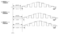
次に、本実施例における送信遅延時間の設定方法につき図10を用いて更に詳しく説明する。本実施例では既に述べたように駆動信号の包絡線遅延を超音波診断装置本体203の送受信部3において行ない、駆動信号の位相遅延を超音波プローブ200のプローブ内送受信部2において行なう。図10(a)は、駆動信号生成部22−1において生成された振動素子1−1に対する駆動信号、図10(b)及び図10(c)は、共通接続部23によって共通接続された駆動信号生成部22−2及び22−3において生成された振動素子1−2及び1−3に対する駆動信号を示す。
Next, the transmission delay time setting method in this embodiment will be described in more detail with reference to FIG. In this embodiment, as already described, the envelope delay of the drive signal is performed in the transmission /
既に図4に示したように、振動素子1−2に対して設定される遅延時間τt(1)の基準遅延時間τtn(1)と振動素子1−2に対して設定される遅延時間τt(2)の基準遅延時間τtn(2)は異なるため、振動素子1−1に対する駆動信号は基準遅延時間τtn(1)を有した包絡線と送信遅延時間τt(1)を有した位相によって構成され、振動素子1−2に対する駆動信号は基準遅延時間τtn(2)を有した包絡線と送信遅延時間τt(2)を有した位相によって形成される。 As already shown in FIG. 4, the reference delay time τtn (1) of the delay time τt (1) set for the vibrating element 1-2 and the delay time τt ( Since the reference delay time τtn (2) of 2) is different, the drive signal for the vibration element 1-1 is composed of an envelope having the reference delay time τtn (1) and a phase having the transmission delay time τt (1). The drive signal for the vibrating element 1-2 is formed by an envelope having a reference delay time τtn (2) and a phase having a transmission delay time τt (2).
一方、振動素子1−3に対して設定される遅延時間τt(3)の基準遅延時間と振動素子1−2に対して設定される遅延時間τt(2)の基準遅延時間は何れもτtn(2)であるため駆動信号生成部22−2と駆動信号生成部22−3は共通接続され、振動素子1−3に対する駆動信号は基準遅延時間τtn(2)を有した包絡線と送信遅延時間τt(3)を有した位相によって形成される。 On the other hand, the reference delay time of the delay time τt (3) set for the vibrating element 1-3 and the reference delay time of the delay time τt (2) set for the vibrating element 1-2 are both τtn ( 2), the drive signal generator 22-2 and the drive signal generator 22-3 are connected in common, and the drive signal for the vibrating element 1-3 is an envelope having a reference delay time τtn (2) and a transmission delay time. It is formed by a phase having τt (3).
振動素子1−1乃至1−M1に対する駆動信号の遅延時間を制御して超音波を所定方向に送信あるいは所定距離に収束する場合、サイドローブの少ない良好な音場を形成するためには遅延時間を精度良く設定する必要があるが、特に位相遅延を正確に設定しなくてはならない。一方、包絡線遅延に対しては高い精度を要求されない。従がって、本実施例では、同じ基準遅延時間間隔Δτtnに含まれた送信遅延時間τtが設定された駆動信号生成部22を共通接続することによりケーブル201のチャンネル数をM0に低減し、このケーブル201を介して基準遅延時間τtnを有した包絡線波形が供給されたプローブ内送受信部2の駆動信号生成部22は、この包絡線波形を送信遅延時間τtを有した矩形信号に基づいてスイッチングすることにより正確な位相遅延を有した駆動信号を生成する。
When controlling the delay time of the drive signal for the vibration elements 1-1 to 1-M1 and transmitting the ultrasonic wave in a predetermined direction or converging to a predetermined distance, the delay time is used to form a good sound field with few side lobes. Must be set with high precision, but in particular, the phase delay must be set accurately. On the other hand, high accuracy is not required for the envelope delay. Therefore, in the present embodiment, the number of channels of the
次に、本実施例における受信遅延時間の設定方法につき図11を用いて補足説明する。図11は、振動素子1−1乃至1−9に対して設定された受信遅延時間τr(1)乃至τr(9)を模式的に示したものであり、夫々の振動素子1から得られた受信信号に対して設定される受信遅延時間τr(1)乃至τr(9)は基準遅延時間τrn(1)乃至τrn(3)と遅延時間差Δτr(1)乃至Δτr(9)(受信遅延時間τrと基準遅延時間τrnの差)に分離される。そして、遅延時間差Δτr(1)乃至Δτr(9)はプローブ内送受信部2の整相加算部24によって与えられ、基準遅延時間τrn(1)乃至τrn(3)は超音波診断装置本体203の受信部32におけるビームフォーマ323によって与えられる。
Next, a supplementary description will be given of a method for setting the reception delay time in this embodiment with reference to FIG. FIG. 11 schematically shows the reception delay times τr (1) to τr (9) set for the vibrating elements 1-1 to 1-9, and are obtained from the respective vibrating
例えば、振動素子1−4乃至1−6によって得られた受信信号の各々には前記整相加算部24において遅延時間差Δτr(4)、Δτr(5)及びΔτr(6)が与えられて加算合成され、更に、前記ビームフォーマ323において基準遅延時間τrn(3)が与えられる。
For example, the delay time differences Δτr (4), Δτr (5), and Δτr (6) are given to each of the received signals obtained by the vibrating elements 1-4 to 1-6 in the
以上述べた本発明の実施例によれば、超音波プローブ内に配列された複数個の振動素子を駆動して超音波を所定方向に送信あるいは所定距離に収束する際に、駆動信号の包絡線遅延を超音波診断装置本体に設けた送受信部で行ない、駆動信号の位相遅延を超音波プローブに内蔵された駆動信号生成部で行なうことにより、遅延時間精度をあまり劣化させることなくケーブルのチャンネル数を低減することができる。従がって、超音波プローブの操作性を損なうことなく良質な画像データを得ることが可能となる。 According to the embodiments of the present invention described above, when driving a plurality of vibration elements arranged in an ultrasonic probe to transmit ultrasonic waves in a predetermined direction or converge at a predetermined distance, an envelope of a drive signal The delay is performed by the transmitter / receiver provided in the main body of the ultrasonic diagnostic apparatus, and the phase delay of the drive signal is performed by the drive signal generator built in the ultrasonic probe, so that the number of channels of the cable can be reduced without much deterioration in delay time accuracy. Can be reduced. Therefore, it is possible to obtain good quality image data without impairing the operability of the ultrasonic probe.
又、前記送受信部は、任意の包絡線波形を容易に生成することができるため、例えば、ガウス型の包絡線波形を有した送信超音波を放射することにより送信超音波の高調波成分が大幅に低減される。このため、THI法等において被検体組織や体内に注入された超音波造影剤の非線型現象によって発生する高調波成分を高感度で受信することができる。 In addition, since the transmission / reception unit can easily generate an arbitrary envelope waveform, for example, by radiating a transmission ultrasonic wave having a Gaussian envelope waveform, the harmonic component of the transmission ultrasonic wave is greatly increased. Reduced to For this reason, the harmonic component generated by the nonlinear phenomenon of the ultrasound contrast agent injected into the subject tissue or body in the THI method or the like can be received with high sensitivity.
更に、パルスインバージョン法のような同一部位に対する複数回の超音波送受信が不要となるためフレームレートを低減することなく高調波成分の低減が可能となる。 Furthermore, since it is not necessary to transmit and receive multiple times of ultrasonic waves to the same site as in the pulse inversion method, harmonic components can be reduced without reducing the frame rate.
一方、上述の実施例における駆動信号は、包絡線波形を所定の位相遅延を有した矩形信号でスイッチングすることによって生成されるため、回路構成が簡単となり、超音波プローブの大きさや重さを許容範囲内に抑えた状態で多くの振動素子と駆動回路を前記超音波プローブ内に内蔵させることが可能となる。 On the other hand, since the drive signal in the above-described embodiment is generated by switching the envelope waveform with a rectangular signal having a predetermined phase delay, the circuit configuration is simplified and the size and weight of the ultrasonic probe are allowed. It is possible to incorporate a large number of vibration elements and drive circuits in the ultrasonic probe while being kept within the range.
以上、本発明の実施例について述べてきたが、本発明は上記の実施例に限定されるものではなく、変形して実施することが可能である。例えば、上述の実施例では振動素子1を2次元配列した超音波プローブ200について述べたが、多くの振動素子1を1次元配列した超音波プローブであってもよい。
As mentioned above, although the Example of this invention has been described, this invention is not limited to said Example, It can change and implement. For example, in the above-described embodiment, the ultrasonic probe 200 in which the
又、同一の振動素子1を用いて送信超音波の放射と受信超音波の受信を行なう場合について述べたが、送信専用の振動素子1あるいは受信専用の振動素子1が含まれていても構わない。但し、送信専用あるいは受信専用のチャンネルに対してはプローブ内送受信部2の送受信切り換え部25及び送受信部3の送受信切り換え部33は不要となる。
In addition, although the case where transmission ultrasonic waves are emitted and reception ultrasonic waves are received using the
更に、RAM314にプリセットされた包絡線データの読み出し周期T1を駆動信号生成部22における包絡線波形のスイッチング周期T0に等しく設定することが望ましいが、これに限定されない。
Furthermore, it is desirable to set the envelope data read cycle T1 preset in the
一方、上述の実施例では送信部31により駆動信号の包絡線波形を任意の形状に設定することが可能であることを述べたが、同様の構成により任意の大きさ(振幅)に設定することも可能である。従がって、駆動信号の重み付けが可能となり、サイドローブの大きさと送信ビーム幅の最適化が可能となる。
On the other hand, in the above-described embodiment, it has been described that the envelope waveform of the drive signal can be set to an arbitrary shape by the
又、超音波連続波を用いてドプラ信号の計測を行なう場合にはRAM314より直流波形を発生してもよいが、図12に示すように切り換え部317を介して電源部から直流電圧を供給してもよい。この方法によれば、直流電圧の供給源インピーダンスを低くすることができるため共通接続に伴う電圧変動を低減することができる、
更に、図3において駆動信号生成部22は、正極性(片極性)の包絡線波形をスイッチングして駆動信号を生成する場合について述べたが、図13に示すような両極性の波形をスイッチングして駆動信号を生成してもよい。この方法によれば直流成分を考慮する必要がなくなるためリニアドライバ316等の回路構成を簡単にすることが可能となる。但し、図13は、駆動信号生成方法の変形例を示したものであり、図13(a)は、超音波診断装置本体203の送受信部3より供給されるガウス型の両極性波形、図3(b)は、プローブ内送受信部2における駆動信号生成部22の矩形信号発生器222から出力される矩形信号、図3(c)は、チョッパ回路221から出力される駆動信号を示している。
In addition, when measuring a Doppler signal using an ultrasonic continuous wave, a DC waveform may be generated from the
Further, in FIG. 3, the drive
一方、ビームフォーマ323及び整相加算部24では、複数方向からの受信超音波の各々を分離して受信する、所謂、並列同時受信の機能を有していてもよい。
On the other hand, the
1…振動素子
2…プローブ内送受信部
3…送受信部
4…データ生成部
5…画像データ記憶・処理部
6…表示部
7…基準信号発生部
8…遅延時間設定部
9…入力部
10…システム制御部
22…駆動信号生成部
23…共通接続部
24…整相加算部
25、33…送受信切り換え部
31…送信部
32…受信部
41…Bモードデータ生成部
42…カラードプラデータ生成部
51…画像データ記憶部
52…画像データ処理部
200…超音波プローブ
201…送受信信号用ケーブル
202…制御信号用ケーブル
203…超音波診断装置本体
221…チョッパ回路
222…矩形信号発生器
311…レートパルス発生器
312…送信遅延回路
313…包絡線波形生成回路
314…RAM
315…D/A変換器
316…リニアドライバ
321…プリアンプ
322…A/D変換器
323…ビームフォーマ
1000…超音波診断装置
DESCRIPTION OF
315 ... D /
Claims (10)
前記複数の振動素子の各々に対し第1の送信遅延時間を有した駆動信号を生成する複数チャンネルの駆動信号生成手段と、
前記駆動信号の包絡線を形成するために第2の送信遅延時間を有した包絡線波形を生成する包絡線波形生成手段と、
被検体の所定方向に超音波送信を行なうための前記第1の送信遅延時間及び前記第2の送信遅延時間を設定する遅延時間設定手段と、
前記第1の送信遅延時間の大きさに基づいて前記駆動信号生成手段を共通接続して複数の駆動信号生成手段群を形成し、これらの駆動信号生成手段群の各々に対して前記包絡線波形を供給する共通接続手段と、
前記振動素子によって得られた前記被検体からの超音波反射波に基づく受信信号を整相加算処理する受信手段と、
この受信手段によって得られた整相加算信号に基づいて画像データを生成する画像データ生成手段を備え、
前記駆動信号生成手段は、前記共通接続手段を介して前記包絡線波形生成手段から供給された包絡線波形と前記第1の送信用遅延時間に基づいて前記駆動信号を生成することを特徴とする超音波診断装置。 An ultrasonic probe including a plurality of arranged vibration elements;
A plurality of channels of drive signal generating means for generating a drive signal having a first transmission delay time for each of the plurality of vibration elements;
An envelope waveform generating means for generating an envelope waveform having a second transmission delay time to form an envelope of the drive signal;
Delay time setting means for setting the first transmission delay time and the second transmission delay time for performing ultrasonic transmission in a predetermined direction of the subject;
Based on the magnitude of the first transmission delay time, the drive signal generation means are connected in common to form a plurality of drive signal generation means groups, and the envelope waveform for each of these drive signal generation means groups A common connection means for supplying
Receiving means for performing phasing addition processing on a reception signal based on an ultrasonic wave reflected from the subject obtained by the vibration element;
Image data generating means for generating image data based on the phasing addition signal obtained by the receiving means,
The drive signal generation unit generates the drive signal based on an envelope waveform supplied from the envelope waveform generation unit via the common connection unit and the first transmission delay time. Ultrasonic diagnostic equipment.
前記第2の送受信手段は、
前記駆動信号の包絡線を形成するために前記遅延時間設定手段が設定した第2の送信遅延時間を有した包絡線波形を生成する包絡線波形生成手段を備え、
前記第1の送受信手段は、
前記遅延時間設定手段が設定した第1の送信遅延時間を有した駆動信号を生成し前記振動素子に供給する複数チャンネルの駆動信号生成手段と、
前記第1の送信遅延時間の大きさに基づいて前記駆動信号生成手段を共通接続して複数の駆動信号生成手段群を形成し、これらの駆動信号生成手段群の各々に対して前記包絡線波形生成手段が生成した包絡線波形を供給する共通接続手段を備え、
前記駆動信号生成手段は、前記共通接続手段を介して前記包絡線波形生成手段から供給された包絡線波形と前記第1の送信用遅延時間に基づいて前記駆動信号を生成することを特徴とする超音波診断装置。 An ultrasonic probe having a plurality of arranged vibration elements and first transmission / reception means for performing transmission / reception with respect to these vibration elements, and connected to the first transmission / reception means via a cable of a plurality of channels In an ultrasonic diagnostic apparatus comprising: a second transmission / reception unit; and a delay time setting unit that sets a transmission delay time of a drive signal supplied to the vibration element to perform ultrasonic transmission in a predetermined direction of the subject.
The second transmitting / receiving means includes
An envelope waveform generating means for generating an envelope waveform having a second transmission delay time set by the delay time setting means to form an envelope of the drive signal;
The first transmitting / receiving means includes
A plurality of channels of drive signal generation means for generating a drive signal having a first transmission delay time set by the delay time setting means and supplying the drive signal to the vibration element;
Based on the magnitude of the first transmission delay time, the drive signal generation means are connected in common to form a plurality of drive signal generation means groups, and the envelope waveform for each of these drive signal generation means groups A common connecting means for supplying an envelope waveform generated by the generating means;
The drive signal generation means generates the drive signal based on an envelope waveform supplied from the envelope waveform generation means via the common connection means and the first transmission delay time. Ultrasonic diagnostic equipment.
Priority Applications (1)
| Application Number | Priority Date | Filing Date | Title |
|---|---|---|---|
| JP2005105188A JP4599208B2 (en) | 2005-03-31 | 2005-03-31 | Ultrasonic diagnostic equipment |
Applications Claiming Priority (1)
| Application Number | Priority Date | Filing Date | Title |
|---|---|---|---|
| JP2005105188A JP4599208B2 (en) | 2005-03-31 | 2005-03-31 | Ultrasonic diagnostic equipment |
Publications (2)
| Publication Number | Publication Date |
|---|---|
| JP2006280639A JP2006280639A (en) | 2006-10-19 |
| JP4599208B2 true JP4599208B2 (en) | 2010-12-15 |
Family
ID=37403155
Family Applications (1)
| Application Number | Title | Priority Date | Filing Date |
|---|---|---|---|
| JP2005105188A Expired - Fee Related JP4599208B2 (en) | 2005-03-31 | 2005-03-31 | Ultrasonic diagnostic equipment |
Country Status (1)
| Country | Link |
|---|---|
| JP (1) | JP4599208B2 (en) |
Cited By (1)
| Publication number | Priority date | Publication date | Assignee | Title |
|---|---|---|---|---|
| US11660075B2 (en) | 2016-12-16 | 2023-05-30 | Canon Medical Systems Corporation | Ultrasound diagnosis apparatus and ultrasound probe |
Families Citing this family (2)
| Publication number | Priority date | Publication date | Assignee | Title |
|---|---|---|---|---|
| JP2010213884A (en) * | 2009-03-17 | 2010-09-30 | Aloka Co Ltd | Ultrasonic diagnostic device |
| KR101656368B1 (en) * | 2015-11-05 | 2016-09-09 | 영남대학교 산학협력단 | Method and apparatus for improving the transmitting and receiving directivity in long-range ultrasonic testing |
Family Cites Families (5)
| Publication number | Priority date | Publication date | Assignee | Title |
|---|---|---|---|---|
| DE69634112T2 (en) * | 1995-10-10 | 2005-12-08 | Advanced Technology Laboratories, Inc., Bothell | Ultrasound imaging for diagnostics using contrast agents |
| JP3665408B2 (en) * | 1996-02-29 | 2005-06-29 | 株式会社東芝 | Drive pulse generator |
| JP4382884B2 (en) * | 1996-11-08 | 2009-12-16 | コーニンクレッカ フィリップス エレクトロニクス エヌ ヴィ | Ultrasonic image processing method and apparatus using harmonics |
| JP3851704B2 (en) * | 1997-05-08 | 2006-11-29 | 株式会社東芝 | Ultrasonic diagnostic equipment |
| JP3302946B2 (en) * | 1999-07-01 | 2002-07-15 | 松下電器産業株式会社 | Ultrasonic transmission / reception method and ultrasonic diagnostic apparatus |
-
2005
- 2005-03-31 JP JP2005105188A patent/JP4599208B2/en not_active Expired - Fee Related
Cited By (1)
| Publication number | Priority date | Publication date | Assignee | Title |
|---|---|---|---|---|
| US11660075B2 (en) | 2016-12-16 | 2023-05-30 | Canon Medical Systems Corporation | Ultrasound diagnosis apparatus and ultrasound probe |
Also Published As
| Publication number | Publication date |
|---|---|
| JP2006280639A (en) | 2006-10-19 |
Similar Documents
| Publication | Publication Date | Title |
|---|---|---|
| US20180206820A1 (en) | Ultrasound apparatus and method | |
| JP4582827B2 (en) | Ultrasonic diagnostic equipment | |
| JP4920302B2 (en) | Ultrasonic diagnostic apparatus and ultrasonic measurement method | |
| JP2000107182A (en) | Ultrasound diagnostic equipment | |
| CN102365054B (en) | Ultrasonograph and urtrasonic processing device | |
| JP6559808B2 (en) | Ultrasonic system and method of operating an ultrasonic system | |
| CN111110277B (en) | Ultrasonic imaging method, ultrasonic apparatus, and storage medium | |
| JP2006197967A (en) | Ultrasonic diagnostic apparatus and ultrasonic image display apparatus | |
| JP2017159028A (en) | Ultrasound diagnostic apparatus | |
| JP5714221B2 (en) | Ultrasonic diagnostic apparatus and ultrasonic transmission / reception method | |
| JP2005342194A (en) | Ultrasonic diagnostic equipment | |
| JP2011115457A (en) | Ultrasonograph and program for controlling for displaying brightness change curve | |
| JP2023114623A (en) | ultrasound diagnostic equipment | |
| JP2003334192A (en) | Ultrasound diagnostic equipment | |
| JP4599208B2 (en) | Ultrasonic diagnostic equipment | |
| JP5627171B2 (en) | Ultrasonic diagnostic equipment | |
| KR20150118732A (en) | ultrasonic apparatus and control method for the same | |
| US10687782B2 (en) | Ultrasound imaging system with a transmit pulse sequence generator circuit | |
| WO2013176112A1 (en) | Ultrasonic image generating method and ultrasonic image diagnostic device | |
| JP5087324B2 (en) | Ultrasonic diagnostic equipment | |
| Wang et al. | Portable and cost-effective handheld ultrasound system utilizing fpga-based synthetic aperture imaging | |
| JP2014083142A (en) | Ultrasonic diagnostic apparatus | |
| JP5016782B2 (en) | Ultrasonic diagnostic equipment | |
| JP2012005789A (en) | Ultrasonograph | |
| JP2007135994A (en) | Ultrasonic diagnosis apparatus and method for generating ultrasonic image data |
Legal Events
| Date | Code | Title | Description |
|---|---|---|---|
| A621 | Written request for application examination |
Free format text: JAPANESE INTERMEDIATE CODE: A621 Effective date: 20080331 |
|
| TRDD | Decision of grant or rejection written | ||
| A01 | Written decision to grant a patent or to grant a registration (utility model) |
Free format text: JAPANESE INTERMEDIATE CODE: A01 Effective date: 20100831 |
|
| A01 | Written decision to grant a patent or to grant a registration (utility model) |
Free format text: JAPANESE INTERMEDIATE CODE: A01 |
|
| A61 | First payment of annual fees (during grant procedure) |
Free format text: JAPANESE INTERMEDIATE CODE: A61 Effective date: 20100927 |
|
| R150 | Certificate of patent or registration of utility model |
Ref document number: 4599208 Country of ref document: JP Free format text: JAPANESE INTERMEDIATE CODE: R150 Free format text: JAPANESE INTERMEDIATE CODE: R150 |
|
| FPAY | Renewal fee payment (event date is renewal date of database) |
Free format text: PAYMENT UNTIL: 20131001 Year of fee payment: 3 |
|
| S111 | Request for change of ownership or part of ownership |
Free format text: JAPANESE INTERMEDIATE CODE: R313117 |
|
| R350 | Written notification of registration of transfer |
Free format text: JAPANESE INTERMEDIATE CODE: R350 |
|
| S533 | Written request for registration of change of name |
Free format text: JAPANESE INTERMEDIATE CODE: R313533 |
|
| R350 | Written notification of registration of transfer |
Free format text: JAPANESE INTERMEDIATE CODE: R350 |
|
| LAPS | Cancellation because of no payment of annual fees |