CN101644873B - Display processing apparatus and method - Google Patents
Display processing apparatus and method Download PDFInfo
- Publication number
- CN101644873B CN101644873B CN2009101627014A CN200910162701A CN101644873B CN 101644873 B CN101644873 B CN 101644873B CN 2009101627014 A CN2009101627014 A CN 2009101627014A CN 200910162701 A CN200910162701 A CN 200910162701A CN 101644873 B CN101644873 B CN 101644873B
- Authority
- CN
- China
- Prior art keywords
- designator
- value
- exposure correction
- unit
- display processing
- Prior art date
- Legal status (The legal status is an assumption and is not a legal conclusion. Google has not performed a legal analysis and makes no representation as to the accuracy of the status listed.)
- Expired - Fee Related
Links
Images


Classifications
-
- G—PHYSICS
- G03—PHOTOGRAPHY; CINEMATOGRAPHY; ANALOGOUS TECHNIQUES USING WAVES OTHER THAN OPTICAL WAVES; ELECTROGRAPHY; HOLOGRAPHY
- G03B—APPARATUS OR ARRANGEMENTS FOR TAKING PHOTOGRAPHS OR FOR PROJECTING OR VIEWING THEM; APPARATUS OR ARRANGEMENTS EMPLOYING ANALOGOUS TECHNIQUES USING WAVES OTHER THAN OPTICAL WAVES; ACCESSORIES THEREFOR
- G03B7/00—Control of exposure by setting shutters, diaphragms or filters, separately or conjointly
-
- H—ELECTRICITY
- H04—ELECTRIC COMMUNICATION TECHNIQUE
- H04N—PICTORIAL COMMUNICATION, e.g. TELEVISION
- H04N23/00—Cameras or camera modules comprising electronic image sensors; Control thereof
- H04N23/70—Circuitry for compensating brightness variation in the scene
- H04N23/743—Bracketing, i.e. taking a series of images with varying exposure conditions
Landscapes
- Engineering & Computer Science (AREA)
- Multimedia (AREA)
- Signal Processing (AREA)
- Physics & Mathematics (AREA)
- General Physics & Mathematics (AREA)
- Studio Devices (AREA)
- Indication In Cameras, And Counting Of Exposures (AREA)
- Exposure Control For Cameras (AREA)
Abstract
The invention provides a display process apparatus and a method therefore. The display processing apparatus which makes it possible to set auto bracketing values while confirming a whole range of shooting conditions configurable for correction in which possible shooting condition corrections are taken into account. An exposure correction value is set based on an instruction from a user for correcting a preset value of exposure. Auto bracketing value auto bracketing shooting are set based on an instruction from the user. A process is carried out for displaying a scale for indicating values of the exposure correction value and the auto bracketing values, indicators indicative of a range of exposure correction values that can be set and are arranged in a manner associated with the scale, and indicators indicative of a range of auto bracketing values that can be set and are arranged in a manner associated with the scale and the first indicators.
Description
Technical field
The present invention relates to relevant display processing device and method and the recording mediums of picture pick-up device such as a kind of and digital camera, relate in particular to a kind of technology that is used for being provided with the automatic encirclement value (auto bracketing Value) that imaging conditions corrected value and imaging conditions proofread and correct.
Background technology
Traditionally, developed the picture pick-up devices such as digital camera with exposure correction function, wherein, exposure correction function makes the user can proofread and correct the correct exposure value that is provided with automatically by picture pick-up device.In addition; Also developed picture pick-up device with Auto exposure bracketing function (AEB); Wherein, The Auto exposure bracketing function is corrected into overexposure or under-exposure automatically with exposure value, and takes a plurality of frames with reference to by the correct exposure value of the automatic setting of picture pick-up device or the exposure correction value that is provided with by the user.
Usually, this type picture pick-up device can be provided with exposure correction value with reference to the display frame shown in Figure 18 A the time, and automatic encirclement value can be set with reference to the display frame shown in Figure 18 B the time.
In addition; Developed a kind of like this technology; The indicating section of this technology through showing exposure correction information interrelatedly surrounds the indicating section of step-lengths with all, make can confirm at once exposure correction information and with the automatic encirclement of all number of times corresponding automatic encirclement step-length (referring to Jap.P. 2646491) of making a video recording.
Yet, in technology, in automatic encirclement value is set, can not when confirm considering the whole exposure correction possible range of possible exposure correction, carry out this setting according to Jap.P. 2646491, this is inconvenient to the user.
Not only in automatic encirclement function about exposure correction; And when the suitable preset value of proofreading and correct about various imaging conditions such as illumination control, shutter speed, f-number, white balance, ISO light sensitivity, automatically snap in the automatic encirclement function of a plurality of frames, take place and above-mentioned similar problem.
Summary of the invention
The present invention provides a kind of display processing device and method that automatic encirclement value can be set that make when the whole imaging conditions of confirming the imaging conditions correction that consideration is possible is proofreaied and correct possible range.
In first aspect of the present invention, a kind of display processing device is provided, comprising: proofread and correct the unit is set, be used for the value of specific shooting configuration is arranged to based on the corrected value after proofreading and correct from user's instruction; Automatically the encirclement value is provided with the unit, is used for based on the instruction from said user, and the automatic encirclement value in the automatic encirclement shooting is set; And display processing unit; Be used for the processing of display scale, first designator and second designator; Wherein, Said scale is used to represent the unit is set and said automatic encirclement value is provided with the value that the unit is provided with by said correction; Said first designator representes that said correction is provided with the scope of the value that the unit can be provided with and arranges with the mode that is associated with said scale, and said second designator representes that said automatic encirclement value is provided with the scope of the value that the unit can be provided with and arranges with the mode that is associated with said scale and said first designator.
In second aspect of the present invention, a kind of display processing method is provided, comprising: the value of specific shooting configuration is arranged to based on the corrected value after proofreading and correct from user's instruction; Based on instruction, the automatic encirclement value in the automatic encirclement shooting is set from said user; And the processing that is used for display scale, first designator and second designator; Wherein, Said scale is used to represent the set value that is provided with through the setting of said corrected value and said automatic encirclement value; Said first designator representes the scope of the value that the setting through said corrected value can be provided with and arranges with the mode that is associated with said scale, and said second designator is represented the scope of the value that the setting through said automatic encirclement value can be provided with and arranged with the mode that is associated with said scale and said first designator.
In the third aspect of the invention; A kind of computer readable recording medium storing program for performing is provided; It stores and is used to make computing machine to be used as the computer executable program like lower unit: proofread and correct the unit is set, be used for the value of specific shooting configuration is arranged to based on the corrected value after proofreading and correct from user's instruction; Automatically the encirclement value is provided with the unit, is used for based on the instruction from said user, and the automatic encirclement value in the automatic encirclement shooting is set; And display processing unit; Be used for the processing of display scale, first designator and second designator; Wherein, Said scale is used to represent the unit is set and said automatic encirclement value is provided with the value that the unit is provided with by said correction; Said first designator representes that said correction is provided with the scope of the value that the unit can be provided with and arranges with the mode that is associated with said scale, and said second designator representes that said automatic encirclement value is provided with the scope of the value that the unit can be provided with and arranges with the mode that is associated with said scale and said first designator.
According to the present invention; With the interrelated ground of scale of all values that can be provided with under the situation of using imaging conditions calibration function and automatic encirclement function in combination, the designator of the designator of all imaging conditions corrected values that data representing can be provided with and all automatic encirclement values of representing to be provided with.
Therefore, can when the whole imaging conditions of confirming the imaging conditions correction that consideration is possible is proofreaied and correct possible range, automatic encirclement value be set.
Through the detailed description below in conjunction with accompanying drawing, it is more obvious that feature and advantage of the present invention will become.
Description of drawings
Fig. 1 is the outside drawing of the picture pick-up device (digital Single-sens reflex camera) according to the embodiment of the invention;
Fig. 2 is the figure that the inner structure of picture pick-up device shown in Figure 1 is shown;
Fig. 3 is the block diagram that the circuit structure of picture pick-up device shown in Figure 1 is shown;
Fig. 4 is the process flow diagram of overview that is used to show the processing of exposure correction/AEB configuration picture;
Fig. 5 is the detail flowchart of data acquisition process performed in Fig. 4;
Fig. 6 is the detail flowchart of scale display process performed in Fig. 4;
Fig. 7 is the detail flowchart that performed being used to shows the processing of exposure correction configurable range in Fig. 4;
Fig. 8 is the detail flowchart that performed being used to shows the processing of automatic encirclement configurable range in Fig. 4;
Fig. 9 is the detail flowchart that performed being used to shows the processing of exposure correction/automatic encirclement value in Fig. 4;
Figure 10 is the detail flowchart that guide display performed in Fig. 4 is handled;
Figure 11 operates the process flow diagram that performed display update is handled through the user when showing that exposure correction/AEB disposes picture;
Figure 12 is the detail flowchart that occurs the processing of (being used for when operation auxiliary electron driver chuck, changing exposure correction value) among Figure 11;
Figure 13 is the detail flowchart that occurs the processing of (being used for when the main electronics driver chuck of operation, changing automatic encirclement value) among Figure 11;
Figure 14 is the figure that the representative example of exposure correction/AEB configuration picture is shown;
Figure 15 A and 15B are used to explain that encirclement value automatically is set to 0 figure with the example of the exposure correction under the situation (only carrying out the situation of exposure correction) that automatic encirclement is not set/AEB configuration picture;
Figure 16 A and 16B are used to explain that the value that encirclement value automatically is arranged to except that 0 disposes the figure of the example of picture with situation (carrying out exposure correction and the situation of surrounding exposure) exposure correction/AEB down that automatic encirclement is set;
Figure 17 A~17I is the figure that the demonstration variation of exposure correction/AEB configuration picture is shown; And
Figure 18 A and 18B are the figure that is used to explain the classic method that exposure correction value and encirclement value are set.
Embodiment
Following reference illustrates the accompanying drawing of embodiments of the invention, specifies the present invention.Fig. 1 is the outside drawing according to the picture pick-up device of the embodiment of the invention, and Fig. 2 is the figure that the inner structure of this picture pick-up device is shown.Picture pick-up device shown in Fig. 1 and 2 is configured to digital Single-sens reflex camera (below be called " camera master unit ") 100.
For example, AE (automatic exposure) locking press button 112 is used for making a video recording through exposure value being fixed to through the determined correct exposure value of a photometry.Focus detection scope selector button 113 is used for selecting the focus detection scope in AF (automatic focusing) control.Release-push 114 is used to indicate camera operation.
Through being operated with other action button, main electronics dial 411 is used to import the value that is associated with the operation of camera, and is used between image pickup mode, switching.Utilize for example liquid crystal panel realization outernal display unit 409, and outernal display unit 409 shows shutter speed values, f-number, image pickup mode and out of Memory.
Should note; For the exposure correction/AEB that picture is switched among Figure 14 disposes picture; Only need after show above-mentioned menu screen, under the state that uses auxiliary electron driver chuck 116 and main electronics driver chuck 411 to select exposure correction/AEB to be provided with, press button 117 is set.
In addition, be furnished with mirror 130 in the shooting light path in camera master unit 100.Mirror 130 can move between following two positions: mirror 130 reflects the position that position (position shown in Figure 2) and mirror 130 from the object light of lens unit 310 withdraws from the shooting light path to finder optical system.Through the object light that is reflected from mirror 130, on focusing board 204, form by subject image.
In addition, imaging apparatus 14 is connected with printed circuit board (PCB) 211.Display board 215 is placed the position at printed circuit board (PCB) 211 rears.LCD unit 417 and backlight 416 is placed display board 215 with printed circuit board (PCB) 211 facing surfaces on.
Then the circuit structure with reference to figure 3 camera master units 100 and lens changeable 300 describes.In Fig. 3, with Fig. 1 and 2 in same reference numerals represent the member shown in Fig. 1 and 2.
At first, circuit structure in the lens changeable 300 is described.Lens changeable 300 is provided with the connector 322 and interface 320 that is used for lens changeable 300 is electrically connected to camera master unit 100.Connector 322 makes that with interface 320 lens system controller circuitry 350 can be through the connector 122 and interface 120 that places camera master unit 100, and the camera master unit 100 interior system controller circuit of mentioning with the back 50 communicate.
The various integrated operations of lens system controller circuitry 350 control lens changeables 300.Lens system controller circuitry 350 is provided with the storer that is used to store constant, variable and the computer program etc. that are used for various operations.
Circuit structure in the camera master unit 100 then is described.Withdraw from mirror 130 under the state of shooting light path (under the situation of semi-transparent semi-reflecting lens, mirror 130 keeps being in the shooting light path at mirror 130), the object light through lens unit 310 and aperture 312 gets into imaging apparatuss 14 through the focal plane shutter of opening 12.The object light opto-electronic conversion that imaging apparatus 14 will incide on it becomes analog picture signal, and from imaging apparatus 14 these analog picture signals of output.
A/D converter 16 will convert digital signal to from the analog picture signal of imaging apparatus 14 outputs.Timing generator circuit 18 provides clock signal and control signal to imaging apparatus 14, A/D converter 16 and D/A converter 26 under the control of memorizer control circuit 22 and system controller circuit 50.
The view data that 20 pairs of image processing circuits transmit from A/D converter 16 or carry out pixel interpolation processing and color conversion processing from the view data that memorizer control circuit 22 transmits.In addition, image processing circuit 20 uses from the view data of A/D converter 16 transmission and carries out the predetermined computation processing.Based on this predetermined computation process result, system controller circuit 50 carries out automatic focusing (AF) processing, automatic exposure (AE) processing and flashlamp luminous in advance (EF) and handles, with control shutter controller 40 and focus adjustment part 42 based on the TTL method.
In addition, image processing circuit 20 uses from the view data of A/D converter 16 transmission and carries out the predetermined computation processing, and based on this predetermined computation process result, utilizes the AWB of TTL method to handle (AWB).
The rest image that storer 30 storages are obtained through shooting.In addition, storer 30 as during video camera with the frame buffer of the image in continuous write storage device 200 of set rate or the accessories apparatus 201.Storer 30 also is used as the workspace of system controller circuit 50.
Compression/unfolding circuits 32 uses the known image compression method to compress and the unfolded image data.Compression/unfolding circuits 32 reads the view data that is stored in the storer 30 and handles this view data carried out processed compressed or to launch, and the write store 30 once more of the view data after will handling.
Notice portion 54 is according to the execution of the computer program in the system controller circuit 50, through utilizing character display such as LCD or LED and image or through sounding from unshowned loudspeaker, to the operating conditions of external notification camera and message etc.Notice portion 54 comprises the LCD unit that is arranged in the optical finder 104, and this LCD unit is used to show f-number, shutter speed, degree of focus, warning and exposure correction value about bluring.
For example, through the EEPROM realization nonvolatile memory 56 that can electricity delete/write down, and nonvolatile memory 56 usefulness act on the storer of storage computation machine program etc.In this case, certainly, computer program is stored in the nonvolatile memory 56 with computer-readable mode.This computer program comprise according to below the application program of process flow diagram of Fig. 4~13 mentioned, become computing machine executable this application deployment.Nonvolatile memory 56 also is stored in the value that is provided with in advance set on the GUI picture of menu screen and exposure correction/AEB configuration picture etc., through the set value that is provided with in advance of the main electronics driver chuck 411 of operation and auxiliary electron driver chuck 116 and through the specified image pickup mode information of operator scheme driver chuck 60.
First stroke through to release-push 114 is operated (partly pressing) connection shutter release (SW1) 62, and the operation of the 50 beginning AF processing of shutter release (SW1) 62 indication mechanism controller circuitrys, AE processing, AWB processing and EF processing etc.Through second stroke (pressing entirely) of release-push 114 is connected shutter release (SW2) 64, and the operation of a series of shootings processing of forming by exposure-processed, development treatment and recording processing of shutter release (SW2) 64 indication mechanism controller circuitrys 50 beginnings.
Operation is reproduced button 66 and is begun to reproduce operation with indication mechanism controller circuitry 50; Reproduce operation and be used for reading the view data that is associated with captured image with other accessories apparatus 201, and go up the view data that demonstration is read at image displaying part 28 (LCD unit 417) from storer 30 or memory storage 200.
Operating portion 70 comprises various buttons and various dials such as main electronics dial 411, auxiliary electron driver chuck 116 and pattern driver chuck 60 such as reproducing button 66 and menu button 68.System controller circuit 50 carries out various operations according to the signal from operating portion 70.
The power supply supply of camera master unit 100 is connected and cut off to power switch 72.Simultaneously, can also connect and the power supply supply of cutting off to the lens changeable 300 that is connected with camera master unit 100, external flashing lamp 115 and memory storage 200 through operating power switch 72.
Constitute power-supply controller of electric 80 by battery detection circuit, DC-DC converter, the commutation circuit etc. that is used to switch the piece that is powered.Whether power-supply controller of electric 80 detects has installed battery, cell types and dump energy; Based on this testing result with from the instruction control DC-DC converter of system controller circuit 50, and must to each one that comprises memory storage 200 essential voltage be provided in the time period.
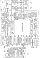
Then dispose picture with reference to exposure correction/AEB that Figure 14~16 explanations are presented on the image displaying part 28 (LCD unit 417).Be stored in the application program in the nonvolatile memory 56 through 50 execution of system controller circuit, be used to show the processing of exposure correction/AEB configuration picture.
The structure in general of exposure correction/AEB configuration picture at first, is described with reference to Figure 14.Shown in figure 14, with the mode of being mutually related, display scale 1405, exposure correction configurable range 1406 and surround configurable range 1407 automatically on exposure correction/AEB configuration picture.
Scale 1405 has the mark that the correct exposure value that is gone out based on the photometry information calculations by system controller circuit 50 is illustrated in all exposure values that can be provided with when Auto exposure bracketing (AEB) function and exposure correction function are used in combination as reference value (0) 1414.
Therefore; Through interrelated ground display scale 1405, exposure correction configurable range 1406 with surround configurable range 1407 automatically; Can be in whole exposure correction possible range that confirm to consider possible exposure correction, automatic encirclement value (a plurality of values when using the Auto exposure bracketing function the set scope from under-exposed side to the overexposure side) is set.In other words, can when confirming to consider the whole imaging conditions correction possible range of possible imaging conditions correction, automatic encirclement value be set.
Show above-mentioned scale 1405 to be fixed on the mode that AEB is provided with the precalculated position of picture.Yet, the quantity of mark, the sum of the exposure correction value that promptly can be provided with is according to whether using the AEB function and difference.Yet no matter whether use the AEB function, the quantity of the mark of expression overexposure light value equals to represent the quantity of the mark of under-exposed value.
In addition, be worth corresponding reference value (0) 1414 with the particular form demonstration that is different from other exposure value with correct exposure, so that can discern this correct exposure value very clearly.In addition, on scale 1405, through with corresponding each numeral integer exposure value of integer exposure value, and represent to comprise between the continuous integral number exposure value exposure value of the numerical value below the radix point through each circle.
In addition, shown in Reference numeral 1413, display string above the mark of overexposure light value " bright ", and shown in Reference numeral 1412, display string above the mark of under-exposure value " secretly ".Show the exposure correction value that these character strings make the user can need not to identify at once will to be provided with thinking deeply and the effect of encirclement value automatically.
For exposure correction configurable range 1406, with scale 1405 on the mode that is associated of mark, show a plurality of rectangle designators respectively.For automatic encirclement configurable range 1407, with scale 1405 on the mode that is associated of mark and the designator in the exposure correction configurable range 1406, show a plurality of rectangle designators respectively.
If (appointments) has been set exposure correction value, then with the state of flicker in exposure correction configurable range 1406 with the corresponding designator of set exposure correction value on demonstration exposure correction cursor 1409.In addition, if (appointments) the has been set automatic encirclement value except that 0 is then being surrounded automatically in the configurable range 1407 and is being disposed each the automatic encirclement that is associated with encirclement automatically and be worth demonstration encirclement cursor 1408 and 1410 on the corresponding designator.Usually, in this case, surround cursors with two of the state demonstrations of flicker, promptly under-exposed side is surrounded cursor 1408 and is surrounded cursor 1410 with the overexposure side.
Should be noted that if (appointment) the has been set automatic encirclement value except that 0, then with the overlapping mode of designator of the center of automatic encirclement configurable range 1407, show exposure correction cursor 1409 with the state of flicker.This means: the designator of center that surrounds configurable range 1407 automatically is all the time with relative with the corresponding designator of set exposure correction value; And, move integratedly with automatic encirclement configurable range 1407 according to by the variation that caused exposure correction value is set.Should move make: when automatic encirclement value was set when exposure correction value is being set after, the user can understand the setting according to automatic encirclement value at once, and how exposure value changes on the whole.
In addition, near the viewing area of exposure correction configurable range 1406 (lateral attitude, left side), show "+/-" icon 1401 that is used for guide, with the prompting user: the designator in the exposure correction configurable range 1406 is used for exposure correction.
In addition, near the viewing area of exposure correction configurable range 1406 (lateral attitude, right side), data representing is used to be provided with the guide of the functional unit of exposure correction value and uses icon, promptly has the guide icon 1403 of the shape of auxiliary electron dial 116.Guide icon 1403 makes the user easily to understand: through operation auxiliary electron driver chuck 116, can specify the designator of (setting) expression exposure correction value.
Near the viewing area that surrounds configurable range 1407 automatically (lateral attitude, left side), show that " AEB " icon 1402 is to point out the user: the designator that surrounds automatically in the configurable range 1407 is associated with encirclement.
In addition, near the viewing area that surrounds configurable range 1407 automatically (lateral attitude, right side), show the guide icon 1404 of shape, be used to be provided with the functional unit of automatic encirclement value with expression with main electronics dial 411.Guide icon 1404 makes the user easily to understand: through operating main electronics driver chuck 411, can specify the designator of the automatic encirclement value of (setting) expression.
Then explain that with reference to Figure 15 exposure correction/AEB that automatic encirclement value equals under 0 the situation disposes picture.
If the encirclement value equals 0 automatically,, then only use exposure correction function to carry out exposure correction if promptly do not use the Auto exposure bracketing function.That is to say that if in fact do not use the Auto exposure bracketing function, all exposure values that then when exposure correction function and Auto exposure bracketing (AEB) function are used in combination, can be provided with only are the exposure values that can be provided with through exposure correction function.
Therefore, equal on the exposure correction/AEB configuration picture under 0 the situation in automatic encirclement value, shown in Figure 15 A, on scale 1501, only show with the exposure value that can be provided with through exposure correction function (2EV~+ mark that 2EV) is associated.
In addition, if the encirclement value equals 0 automatically, then do not show automatic encirclement configurable range, thereby only show the designator of exposure correction configurable range 1502.This makes and can reduce faulty operation or the useless operation during as the automatic encirclement value of being provided with of invalid refusal when automatic encirclement value is set.
Should note; Exposure correction/AEB that the stride that Figure 15 A illustrates exposure correction equals under the situation of 1/3 step-length disposes picture, and with the interval display scale 1504 and the designator in the exposure correction configurable range 1505 (and the quantity of the corresponding designator of black circles between the integer exposure value is 2) of 1/3 step-length.If the stride of exposure correction equals 1/2 step-length, then shown in Figure 15 B, with the interval display scale 1504 and the above-mentioned designator (and the quantity of the corresponding designator of black circles between the integer exposure value is 1) of 1/2 step-length.
Then explain that with reference to Figure 16 exposure correction/AEB that automatic encirclement value is not equal under 0 the situation disposes picture.
If the encirclement value is not equal to 0 automatically,, then use exposure correction function and Auto exposure bracketing function to carry out exposure correction if promptly use the Auto exposure bracketing function.The summation of the exposure value that all exposure values that therefore, when exposure correction function and Auto exposure bracketing (AEB) function are used in combination, can be provided with equal can be provided with through exposure correction function and the exposure value that can be provided with through the Auto exposure bracketing function.
Therefore, be not equal on the exposure correction/AEB configuration picture under 0 the situation in automatic encirclement value, shown in Figure 16 A, on scale 1601, show with exposure value (4EV~+ mark that 4EV) is associated.Exposure value (4EV~+ 4EV) be the exposure value that can be provided with through exposure correction function (2EV~+ 2EV) and the exposure value that can be provided with through the Auto exposure bracketing function (2EV~+ 2EV) summation.
In addition, be not equal under 0 the situation, also show the designator of automatic encirclement configurable range 1606 with the designator of exposure correction configurable range 1605 in automatic encirclement value.Exposure correction/AEB that the stride that Figure 16 A illustrates exposure correction equals under the situation of 1/3 step-length disposes picture; And according to spaced mode with 1/3 step-length, the designator in display scale 1601, the exposure correction configurable range 1605 and surround the designator in the configurable range 1606 automatically.If the stride of exposure correction equals 1/2 step-length, then shown in Figure 16 B, the spaced mode according to 1/2 step-length shows above-mentioned mark and designator.
Then the flowchart text with reference to figure 4 is used to show that exposure correction/AEB disposes the overview of the processing of picture.Should be noted that in the process flow diagram of Fig. 4 S401 etc. have the numeral processed steps numbering of letter " S ".In addition, below with reference to the processing among step S401, S402, S403, S404, S405 and the S406 of the detailed description of the process flow diagram in figure 5,6,7,8,9 and 10 Fig. 4.In addition, in Fig. 4,12 and 13,, for ease, use the Reference numeral among Figure 14 for the Reference numeral of expression scale etc.Should note; Under the state of having selected exposure correction/AEB to be provided with through auxiliary electron driver chuck 116 and main electronics driver chuck 411, press button 117 is set; And be provided with under the situation of demonstration of exposure correction/AEB configuration picture, repeat the processing that is used to show exposure correction/AEB configuration picture with predetermined space.
If the user is provided with exposure correction/AEB through above-mentioned menu screen indication, then system controller circuit 50 obtains demonstration exposure correction/AEB from nonvolatile memory 56 required data (S401) is set.Except that character pattern data that are associated with value and icon pattern data etc., required data also comprise the data of the information relevant with user's stride of set image pickup mode and exposure correction before sending the instruction that exposure correction/AEB is set.Required data also comprise the data of the information that the shutter speed that goes out based on the photometry information calculations with automatic encirclement value, by system controller circuit 50 and f-number etc. are relevant.
Then, system controller circuit 50 is based on the data of relevant information such as above-mentioned encirclement value that obtain and automatic and correction stride, display scale 1405 (S402).Then, system controller circuit 50 shows the designator and the designator (S403 and S404) that surrounds automatically in the configurable range 1407 in the exposure correction configurable range 1406.
Then, system controller circuit 50 perhaps based on the set exposure correction value of user, shows exposure correction cursor 1409 (S405) based on according to the exposure correction value that shutter speed value and f-number calculated.In addition, system controller circuit 50 shows that based on the set automatic encirclement value of user under-exposed side is surrounded cursor 1408 and the overexposure side is surrounded cursor 1410 (S405).
Then, system controller circuit 50 shows guide information (S406), stops being used to show the processing of exposure correction/AEB configuration picture subsequently.The guide information that shows comprises "+/-" icon 1401, " AEB " icon 1402, guide icon 1403 and 1404, character string " secretly " 1412 and " bright " 1413.
Then specify performed data acquisition process among the step S401 of Fig. 4 with reference to the process flow diagram of figure 5.
In this data acquisition process, system controller circuit 50 reads exposure correction value (S501) from nonvolatile memory 56, reads automatic encirclement value (S502), and reads the stride (S503) of exposure correction.
Then, system controller circuit 50 will be used for representing that the exposure correction configuration that whether shows the designator of exposure correction configurable range 1406 allows sign to be arranged to the initial value (S504) of expression " permission ".Similarly, system controller circuit 50 will be used for representing that the encirclement configuration that whether shows the designator of automatic encirclement configurable range 1407 allows sign to be arranged to the initial value (S505) of expression " permission ".
Then, system controller circuit 50 is judged image pickup mode (S506).As a result, if image pickup mode is " Bulb ", promptly long exposure mode then will surround configuration and allow resets to become the value (S507) of expression " forbidding ".Then, allow resets to become the value (S508) of expression " forbidding " the exposure correction configuration, stop this data acquisition process subsequently.
As stated; Surrounding configuration allows sign and exposure correction configuration to allow sign all to be configured to the value of expression " forbidding "; And this causes not showing exposure correction configurable range 1406 and surrounds the designator in the configurable range 1407 automatically that therefore in fact becoming to be provided with exposure correction value and automatic encirclement value.
If image pickup mode is " M ", i.e. manual mode, then system controller circuit 50 allows resets to become the value of expression " forbidding " the exposure correction configuration, so that exposure correction value (S508) cannot be set, stop subsequently and should handle.In addition, if image pickup mode is except that " Bulb " and the pattern " M ", then system controller circuit 50 is judged the current AEB shooting (S509) of whether carrying out.
As a result, if carrying out the AEB shooting, then system controller circuit 50 allows resets to become the value of expression " forbidding " the exposure correction configuration, so that exposure correction value (S508) cannot be set, stops this processing subsequently.On the other hand, if carry out AEB shooting, then system controller circuit 50 stops this processing under the situation that does not change above-mentioned two signs, thereby makes exposure correction value and encirclement value automatically can be set.
Then specify performed scale display process among the step S402 of Fig. 4 with reference to the process flow diagram of figure 6.
In the scale display process, at first, system controller circuit 50 is judged the stride (S601) of exposure correction.Equal 1/2 step-length if be judged as the stride of exposure correction at step S601, then system controller circuit 50 is judged automatic encirclement value (S602).Equal 0 if be judged as automatic encirclement value at step S602, then in the scope of system controller circuit 50 between-2 (EV)~+ 2 (EV) with the interval show tags (S603) of 1/2 step-length, stop the scale display process subsequently.
On the other hand, be not equal to 0 if be judged as automatic encirclement value at step S602, then in the scope of system controller circuit 50 between-4 (EV)~+ 4 (EV) with the interval show tags (S604) of 1/2 step-length, stop the scale display process subsequently.
Equal 1/3 step-length if be judged as the stride of exposure correction at step S601, then system controller circuit 50 is judged automatic encirclement value (S605).Equal 0 if be judged as automatic encirclement value at step S605, then in the scope of system controller circuit 50 between-2 (EV)~+ 2 (EV) with the interval show tags (S606) of 1/3 step-length, stop the scale display process subsequently.
On the other hand, be not equal to 0 if be judged as automatic encirclement value at step S605, then in the scope of system controller circuit 50 between-4 (EV)~+ 4 (EV) with the interval show tags (S607) of 1/3 step-length, stop the scale display process subsequently.
Then specify the processing that performed being used among the step S403 of Fig. 4 shows the exposure correction configurable range with reference to the process flow diagram of figure 7.
In the processing that is used for showing the exposure correction configurable range, system controller circuit 50 judges that the exposure correction configuration allows the setting (S701) of sign.As a result, if the exposure correction configuration allows sign to equal the value of expression " forbidding ", then system controller circuit 50 does not show the special demonstration (S702) of the designator in the exposure correction configurable range 1406, stops this display process subsequently.
On the other hand, if the exposure correction configuration allows sign to equal the value of expression " permission ", then system controller circuit 50 is judged the stride (S703) of exposure correction.As a result, if the stride of exposure correction equals 1/2 step-length, then the interval with 1/2 step-length shows the designator (S704) in the exposure correction configurable range 1406 in the scope of system controller circuit 50 between-2 (EV)~+ 2 (EV), stops this display process subsequently.
On the other hand; If the stride of exposure correction equals 1/3 step-length; Then the interval with 1/3 step-length shows the designator (S705) in the exposure correction configurable range 1406 in the scope of system controller circuit 50 between-2 (EV)~+ 2 (EV), stops this display process subsequently.
Then specify the processing that performed being used among the step S404 of Fig. 4 shows automatic encirclement configurable range with reference to the process flow diagram of figure 8.
In the processing that is used for showing automatic encirclement configurable range, system controller circuit 50 is judged the setting (S801) of surrounding configuration permission sign.As a result, allow sign to equal the value of expression " forbidding " if surround configuration, then system controller circuit 50 does not show the special demonstration (S802) of the designator in the automatic encirclement configurable range 1407, stops this display process subsequently.
On the other hand, allow sign to equal the value of expression " permission " if surround configuration, then system controller circuit 50 is judged the stride (S803) of exposure correction.The result; If the stride of exposure correction equals 1/2 step-length, then system controller circuit 50 " exposure correction value-2 " (EV)~" exposure correction value+2 " in the scope between (EV) interval with 1/2 step-length show the designator (S804) that surrounds automatically in the configurable range 1407.After system controller circuit 50 shows the designator that surrounds automatically in the configurable range 1407, stop this display process.
On the other hand; If the stride of exposure correction equals 1/3 step-length; Then system controller circuit 50 interval with 1/3 step-length shows the designator (S805) that surrounds automatically in the configurable range 1407 at " exposure correction value-2 " (EV) and in " exposure correction value+2 " scope between (EV), stops this display process subsequently.
As stated, in the present embodiment, the indication range of surrounding the designator in the configurable range 1407 automatically is configured to be arranged on " exposure correction value-2 " (EV) and in " exposure correction value+2 " scope between (EV).This makes the designator that surrounds the center of configurable range 1407 automatically be positioned at all the time and the relative position of designator of representing exposure correction value.Therefore, in automatic encirclement value was set, becoming, how the effect of whole exposure correction changed in the time of can being identified in consideration at once and being worth caused exposure correction through automatic encirclement is set.
In other words, can when confirm considering the whole exposure correction possible range of possible exposure correction, automatic encirclement value be set.
Then specify that performed being used to shows exposure correction/processing of encirclement value automatically among the step S405 of Fig. 4 with reference to the process flow diagram of figure 9.
Be used for showing exposure correction/processing of encirclement value automatically, system controller circuit 50 is judged the setting (S901) of surrounding configuration permission sign.The result; Allow sign to equal the value of expression " forbidding " if surround configuration; Then system controller circuit 50 representes that in exposure correction configurable range 1406 position of the designator of exposure correction value shows exposure correction cursor 1409 (S902), stops this display process subsequently.
On the other hand; Allow sign to equal the value of expression " permission " if surround configuration; Then the position of system controller circuit 50 designator of expression " absolute value of exposure correction value-under-exposed side encirclement value automatically " in the designator that surrounds automatically in the configurable range 1407 shows under-exposed side encirclement cursor 1408 (S903).In addition, the position of system controller circuit 50 designator of expression " absolute value of exposure correction value+overexposure side encirclement value automatically " in the designator that surrounds automatically in the configurable range 1407 shows overexposure side encirclement cursor 1410.
Then; System controller circuit 50 with exposure correction configurable range 1406 in the expression exposure correction value designator with automatically surround designator (designator of center) the overlapping mode relative in the configurable range 1407 with the designator of this exposure correction value; Show exposure correction cursor 1409 (S905), stop this display process subsequently.
According to above-mentioned processing; Position at the designator at the center that automatically surrounds configurable range 1407 shows under the state of exposure correction cursor 1409, shows that in the both sides of exposure correction cursor 1409 under-exposed side surrounds cursor 1408 and surround cursor 1410 with the overexposure side.This makes the user want to be provided with automatic encirclement value can easily grasp the effect of the whole exposure correction of the setting of considering exposure correction value.In addition, the user can also easily grasp the departure degree of automatic encirclement value with respect to exposure correction value.
Then the process flow diagram with reference to Figure 10 specifies guide display processing performed among the step S406 of Fig. 4.
In guide display was handled, system controller circuit 50 judged that the exposure correction configuration allows the setting (S1001) of sign.The result; If the exposure correction configuration allows sign to equal the value of expression " forbidding "; Then system controller circuit 50 shows "+/-" icon 1401 and guide icon 1403 (S1002) be associated with exposure correction with grey, handles the step S1004 that mentions below the entering then.
On the other hand; If the exposure correction configuration allows sign to equal the value of expression " permission "; Then system controller circuit 50 shows "+/-" icon 1401 and guide icon 1403 (S1003) be associated with exposure correction with white, handles entering step S1004 then.
At S1004, system controller circuit 50 is judged the setting of surrounding configuration permission sign.As a result, allow sign to equal the value of expression " forbidding " if surround configuration, system controller circuit 50 shows with grey and surrounds " AEB " icon 1402 and guide icon 1404 (S1005) that is associated.
On the other hand, allow sign to equal the value of expression " permission " if surround configuration, then system controller 50 shows with white and surrounds " AEB " icon 1402 and guide icon 1404 (S1006) that is associated.
Should be noted that during showing the time period of guide icon 1403 and 1404 even operation auxiliary electron driver chuck 116 and main electronics driver chuck 411, system controller circuit 50 also should operation as invalid refusal with grey.
As stated, show the icon of proofreading and correct or surrounding with the configuration permission sign corresponding exposure of the value of being arranged to expression " forbidding " with grey, thereby can reduce faulty operation.
Follow the processing of flowchart text under the situation of carrying out user's operation during demonstration exposure correction/AEB configuration picture with reference to Figure 11.
If when showing that exposure correction/AEB disposes picture, the user carries out a certain operation, then the content (S1101) of system controller circuit 50 decision operation.As a result, if operation auxiliary electron driver chuck 116, then system controller circuit 50 upgrades the demonstration of exposure correction value according to operation, i.e. the display position of exposure correction cursor 1409 (S1102), and handle and be back to step S1101.Specify the processing among the S1102 below with reference to Figure 12.
If operate main electronics driver chuck 411, then system controller circuit 50 promptly surround the display position (S1103) of cursor 1408 and 1410, and processing is back to S1101 according to the demonstration of the automatic encirclement value of operation renewal.Specify the processing of step S1103 below with reference to Figure 13.
If the operation setting button, then system controller unit 50 fixes setting (S1104 and S1105) through being stored in automatic encirclement value according to the exposure correction value after the driver chuck control break in the nonvolatile memory 56.Then, system controller circuit 50 is closed exposure correction/AEB and is disposed picture (S1106), stops subsequently handling.
After this, when the automatic encirclement of indication is made a video recording,, make a video recording based on exposure correction value that as above is provided with and automatic encirclement value.In encirclement is made a video recording automatically,,,, repeatedly make a video recording automatically based on exposure correction value that is provided with as stated and automatic encirclement value then in response to single operation to release-push 114 if the encirclement value is not equal to 0 automatically.
In addition, if carry out the operation or the camera operation of menu button at step S1101, then system controller circuit 50 is closed exposure correction/AEB and is disposed picture (S1106), stops subsequently handling.
Then specify performed processing among the step S1102 of Figure 11 with reference to the process flow diagram of Figure 12.
If operation auxiliary electron dial 116, then system controller circuit 50 judges that the exposure correction configuration allows the setting (S1201) of sign.As a result, if the exposure correction configuration allows sign to equal the value of expression " forbidding ", then under the situation of not carrying out any processing, stop this processing.
On the other hand, if the exposure correction configuration allows sign to equal the value of expression " permission ", then system controller circuit 50 is judged the rotation direction (S1202) of auxiliary electron driver chuck 116.As a result, if turn left auxiliary electron dial 116, then system controller circuit 50 value that will be obtained through the step number (rotation step number) that deducts from current exposure correction value with the corresponding exposure correction of rotating operation is set to new exposure correction value (S1203).
The auxiliary electron driver chuck 116 if turn right, then system controller circuit 50 will be set to new exposure correction value (S1204) through the value that will be obtained with the step number (rotation step number) and the current exposure correction value addition of the corresponding exposure correction of rotating operation.
Then, system controller circuit 50 shows exposure correction/processing of encirclement value automatically through being used in the execution graph 9, exposure correction cursor 1409 is moved to the position (S1205) of the designator of the new exposure correction value of expression.In this case, according to moving of exposure correction cursor 1409, also move the encirclement cursor 1408 and 1410 that surrounds configurable range 1407 and be positioned at the both sides of exposure correction cursor 1409 automatically.
Then specify performed processing among the step S1103 of Figure 11 with reference to the process flow diagram of Figure 13.
If operate main electronics driver chuck 411, then system controller circuit 50 is judged the setting (S1301) of surrounding configuration permission sign.As a result, allow sign to equal the value of expression " forbidding ", then under the situation of not carrying out any processing, stop this processing if surround configuration.
On the other hand, allow sign to equal the value of expression " permission " if surround configuration, then system controller circuit 50 is judged the rotation direction (S1302) of main electronics dial 411.The result; The main electronics driver chuck 411 if turn left; Then system controller circuit 50 will deduct through the absolute value from current under-exposed side and overexposure side encirclement value automatically and the corresponding value that step number obtained of surrounding of rotating operation, be set to the absolute value (S1303) of new under-exposed side and overexposure side encirclement value automatically.The main electronics driver chuck 411 if turn right; Then system controller circuit 50 will be set to the absolute value (S1304) of new under-exposed side and overexposure side encirclement value automatically through the value that will be obtained with the absolute value addition of the corresponding step number of surrounding of rotating operation and current under-exposed side and overexposure side encirclement value automatically.
Then, the scale display process (S1305) in system controller circuit 50 execution graphs 5.Since existences need " 4EV~+ 4EV " and " "-2EV~+ 2EV " between the possibility of scope of change scale 1405, thereby execution scale display process.
Then, system controller circuit 50 shows exposure correction/processing of encirclement value automatically through being used in the execution graph 9, is displaced to the position that is worth corresponding designator with new automatic encirclement separately with surrounding cursor 1408 and 1410.
Here, Figure 17 A~17I illustrates the demonstration variation of exposure correction/AEB configuration picture.Should be noted that in Figure 17 A~17I, represent "+/-" icon 1401, " AEB " icon 1402 and guide icon 1403 and 1404 that show with grey by a dotted line.
Exposure correction/AEB that Figure 17 A illustrates under the following situation disposes picture: can carry out exposure correction configuration and encirclement and dispose both, exposure correction value equals 0, and the encirclement value equals 0 automatically, and the stride of exposure correction equals 1/3 step-length.
Exposure correction/AEB that Figure 17 B illustrates under the following situation disposes picture: can carry out exposure correction configuration and encirclement and dispose both, exposure correction value equals 1, and the encirclement value equals 0 automatically, and the stride of exposure correction equals 1/3 step-length.
Exposure correction/AEB that Figure 17 C illustrates under the following situation disposes picture: can carry out exposure correction configuration and encirclement and dispose both; Exposure correction value equals 0; The absolute value of under-exposed side and overexposure side encirclement value automatically equals 1+1/3, and the stride of exposure correction equals 1/3 step-length.
Exposure correction/AEB that Figure 17 D illustrates under the following situation disposes picture: can carry out exposure correction configuration and encirclement and dispose both; Exposure correction value equals 1; The absolute value of under-exposed side and overexposure side encirclement value automatically equals 1+1/3, and the stride of exposure correction equals 1/3 step-length.
Exposure correction/AEB that Figure 17 E illustrates under the following situation disposes picture: can carry out the exposure correction configuration, cannot surround configuration, exposure correction value equals 0, and the stride of exposure correction equals 1/3 step-length.Since cannot surround configuration, thus obviously different with Figure 17 A, show the guide icon of " AEB " icon and the main electronics driver chuck 411 of expression with grey, thereby making to identify to surround configuration.
Exposure correction/AEB that Figure 17 F illustrates under the following situation disposes picture: can carry out the exposure correction configuration, cannot surround configuration, exposure correction value equals 1, and the stride of exposure correction equals 1/3 step-length.
Exposure correction/AEB that Figure 17 G illustrates under the following situation disposes picture: cannot carry out the exposure correction configuration, can surround configuration, the encirclement value equals 0 automatically, and the stride of exposure correction equals 1/3 step-length.Owing to cannot carry out the exposure correction configuration; Thereby it is obviously different with Figure 17 A; Show the guide icon of exposure correction configurable range, "+/-" icon and expression auxiliary electron driver chuck 116 with grey, thereby making to identify to carry out the exposure correction configuration.
Exposure correction/AEB that Figure 17 H illustrates under the following situation disposes picture: cannot carry out the exposure correction configuration; Can surround configuration; The absolute value of under-exposed side and overexposure side encirclement value automatically equals 1+1/3, and the stride of exposure correction equals 1/3 step-length.
Figure 17 I illustrates the exposure correction/AEB that cannot carry out the exposure correction configuration and surround under both situation of configuration and disposes picture.
Present embodiment makes and can easily discern: when considering the exposure correction and encirclement that will be provided with, scale 1405 illustrates the scope of exposure correction with identification mode easily.With identification mode easily the reference value (correct exposure value) 1414 as the value of the center of exposure correction scope is shown.
In addition; Through exposure correction configurable range 1406 with automatically surround the related of configurable range 1407 and scale 1405; Under the exposure correction of promptly considering at the same time to be provided with and the situation of encirclement, can discern exposure correction configurable range 1406 and encirclement configurable range 1407 automatically.In addition, can also discern exposure correction configurable range 1406 and surround the relation between the configurable range 1407 automatically.
"+/-" icon 1401 that is used for guide makes and can identification dispose each demonstration that is associated with exposure correction with surrounding with " AEB " icon 1402.In addition, guide icon 1403 and 1404 makes easily to understand how to dispose exposure correction and encirclement.
Should note; Although in the above-described embodiments; The quantity of the shooting frame in the AEB shooting 3 frames of total that the frame at frame and overexposure light value place at a frame, exposure correction value place at under-exposed value place is formed of serving as reasons, but can also the technology according to the foregoing description be applied in the AEB shooting, to take the situation of 4 or more a plurality of frames.
In addition,, show that through actions menu button 68 exposure correction/AEB disposes picture, can also show that exposure correction/AEB disposes picture through the operating assembly of operation except that menu button 68 although in the above-described embodiments.In addition, can also remove auxiliary electron driver chuck 116 through operation and exposure correction value and automatic encirclement value are set with functional unit main electronics driver chuck 411.As functional unit in this case, can use arrow key, multi-controller, and can use and make it possible to icon that carries out touch operation etc.When use made it possible to carry out the icon of touch operation, preferably the shape of this icon was identical with the shape of auxiliary electron driver chuck 116 and main electronics driver chuck 411.This be because; When the user is provided with exposure correction value with automatic encirclement value, can prevent as much as possible the user make it possible to carry out in use touch operation icon situation and use between the situation of auxiliary electron driver chuck 116 and main electronics driver chuck 411 of physics and obscure functional unit.
In addition, can also be under the situation of not passing through operation setting button 117 final definite exposure correction values and automatic encirclement value, change and definite exposure correction value and automatic encirclement value.In addition, be not must be with equidistant interval show tags and designator, but can be at aspects such as visuality, operability with arranged spaced for not waiting.In addition, not only can be on the display device of camera master unit, but also can on the display device such as display of PC, wireless device and the televisor etc. that are connected with the camera master unit, show that exposure correction/AEB disposes picture.
Although should be noted that in the above-described embodiments, the example that applies the present invention to exposure correction and Auto exposure bracketing has been described, be not limited to this.The present invention can be applicable to any other display processing device; As long as this equipment is used to use the imaging conditions calibration function and surrounds function automatically; Wherein, The imaging conditions calibration function is used to proofread and correct the suitable value that is provided with in advance that calculates based on measured value, be associated with imaging conditions, surrounds function automatically and is used to utilize a plurality of values that are provided with in advance that comprise the imaging conditions corrected value after the correction, automatically snaps a plurality of frames.
For example, the present invention can be applicable to use the illumination control calibration function about the flashlamp shooting to surround the display processing device of function automatically with illumination control.In this case; Only need suitable light quantity that using system controller circuitry 50 calculates based on flash spotter as reference value 1414, be provided with on the scale 1405 that in Figure 14, occurs and be used in combination illumination and control the mark that all light quantities that can be provided with under the situation of calibration function are associated surrounding function automatically with illumination control.
Then, the designator in the configurable range is proofreaied and correct in display lighting control in zone 1406, and the designator in the configurable range is surrounded in display lighting control automatically in zone 1407.Then, can show the various icons proofreaied and correct about illumination control and guide designator etc.Similarly, the present invention can also be applied to use the display processing device of the encirclement shooting that is associated with shutter speed, f-number, white balance and ISO light sensitivity.
Should be appreciated that; Can also realize the present invention as follows: to system or equipment the storage medium of the program code of the software that stores the function that realizes the foregoing description is provided, and makes the computing machine (or CPU or MPU) of this system or equipment read and carry out the program code that is stored in this storage medium.
In this case, the program code itself that reads from storage medium is realized the function of embodiment, so this program code constitutes the present invention with the storage medium that stores this program code.
Be used to provide the example of the storage medium of this program code to comprise CD, tape, Nonvolatile memory card and ROM such as floppy disk (floppy, registered trademark), hard disk, magneto-optic disk, CD-ROM, CD-R, CD-RW, DVD-ROM, DVD-RAM, DVD-RW or DVD+RW.Alternatively, can pass through this program of network download.
In addition, should be appreciated that, the program code that not only can read through object computer, but also can carry out part or all of practical operation based on the instruction of this program code through making operation OS (operating system) on computers etc., realize the foregoing description.
In addition; Should be appreciated that; Can through will write from the program code that storage medium is read in the storer that is arranged on the expansion board of inserting the computing machine or with functional expansion unit that computing machine is connected in storer in; Make CPU of being arranged in this expansion board or the functional expansion unit etc. carry out part or all of practical operation then, realize the foregoing description based on the instruction of this program code.
Although the present invention has been described, should be appreciated that the present invention is not limited to disclosed exemplary embodiments with reference to exemplary embodiments.The scope of appended claims meets the wideest explanation, to comprise all modifications, equivalent structure and function.
The application requires the right of priority of the Japanese 2008-205980 patented claim of submission on August 8th, 2008, and its full content is contained in this by reference.
Claims (9)
1. display processing device comprises:
Correction is provided with the unit, is used for the value of specific shooting configuration is arranged to based on the corrected value after proofreading and correct from user's instruction;
Automatically the encirclement value is provided with the unit, is used for based on the instruction from said user, and the automatic encirclement value in the automatic encirclement shooting is set; And
Display processing unit; Be used for the processing of display scale, first designator and second designator; Wherein, Said scale is used to represent the unit is set and said automatic encirclement value is provided with the value that the unit is provided with by said correction; Said first designator representes that said correction is provided with the scope of the value that the unit can be provided with and arranges with the mode that is associated with the fixed position of said scale; Said second designator representes that said automatic encirclement value is provided with the scope of the value that the unit can be provided with and is positioned at makes the position that is in the central authorities of said second designator with the corresponding position of said corrected value that the unit setting is set by said correction, and arranges with the mode that said scale and said first designator are associated with said second designator
Wherein, said display processing unit is with the mode that other location recognition that can said relatively first designator goes out, and shows that expression in said first designator is provided with the position of the corrected value that the unit is provided with by said correction; Said display processing unit is provided with the position of the corrected value that the unit is provided with and the mode of the association between said second designator can identify in said first designator expression by said correction, shows said first designator and said second designator; And said display processing unit so that be in the central authorities of said second designator respectively with the position of the corresponding scale of corrected value that the unit setting is set by said correction with corresponding position, the position of said first designator, shows said second designator through arranging second designator.
2. display processing device according to claim 1 is characterized in that, at least one in the configuration that said specific shooting configuration is exposure, illumination control, shutter speed, f-number, white balance and ISO light sensitivity.
3. display processing device according to claim 1 is characterized in that, said display processing unit changes the mode that shows said first designator according to whether using the shooting that the corrected value of unit setting is set by said correction.
4. display processing device according to claim 1 is characterized in that, said display processing unit changes the mode that shows said second designator according to whether surrounding shooting automatically.
5. display processing device according to claim 1; It is characterized in that; Said display processing unit is with the mode that other location recognition that can said relatively second designator goes out, and shows that expression in said second designator is provided with the position of the automatic encirclement value that the unit is provided with by said automatic encirclement value.
6. display processing device according to claim 1 is characterized in that, said display processing unit also near said first designator demonstration with said correction the relevant guide information of being provided with of unit is set.
7. display processing device according to claim 1 is characterized in that, said display processing unit also near said second designator demonstration with said automatic encirclement value the relevant guide information of being provided with of unit is set.
8. display processing device according to claim 1 is characterized in that, also comprises being used to use by said correction the image unit that the corrected value of unit setting carries out said automatic encirclement shooting is set.
9. display processing method comprises:
The value of specific shooting configuration is arranged to based on the corrected value after proofreading and correct from user's instruction;
Based on instruction, the automatic encirclement value in the automatic encirclement shooting is set from said user; And
Be used for the processing of display scale, first designator and second designator; Wherein, Said scale is used to represent the set value that is provided with through the setting of said corrected value and said automatic encirclement value; Said first designator is represented the scope of the value that the setting through said corrected value can be provided with and is arranged with the mode that is associated with the fixed position of said scale; Said second designator is represented the scope of the value that the setting through said automatic encirclement value can be provided with and is positioned to make the position that is in the central authorities of said second designator with the corresponding position of set corrected value, and arranges with the mode that is associated with said scale and said first designator
Wherein, with the mode that other location recognition that can said relatively first designator goes out, show the position of the corrected value that expression in said first designator is set; Mode with the association between the central authorities of the position that can identify the set corrected value of expression in said first designator and said second designator shows said first designator and said second designator; And so that be in the central authorities of said second designator respectively, show said second designator with the position of the set corresponding scale of corrected value with corresponding position, the position of said first designator through arranging said second designator.
Applications Claiming Priority (3)
| Application Number | Priority Date | Filing Date | Title |
|---|---|---|---|
| JP2008205980A JP5153512B2 (en) | 2008-08-08 | 2008-08-08 | Display processing apparatus, display processing method, program, and storage medium |
| JP2008-205980 | 2008-08-08 | ||
| JP2008205980 | 2008-08-08 |
Publications (2)
| Publication Number | Publication Date |
|---|---|
| CN101644873A CN101644873A (en) | 2010-02-10 |
| CN101644873B true CN101644873B (en) | 2012-07-04 |
Family
ID=41652567
Family Applications (1)
| Application Number | Title | Priority Date | Filing Date |
|---|---|---|---|
| CN2009101627014A Expired - Fee Related CN101644873B (en) | 2008-08-08 | 2009-08-10 | Display processing apparatus and method |
Country Status (3)
| Country | Link |
|---|---|
| US (2) | US8203641B2 (en) |
| JP (1) | JP5153512B2 (en) |
| CN (1) | CN101644873B (en) |
Families Citing this family (25)
| Publication number | Priority date | Publication date | Assignee | Title |
|---|---|---|---|---|
| JP5153512B2 (en) * | 2008-08-08 | 2013-02-27 | キヤノン株式会社 | Display processing apparatus, display processing method, program, and storage medium |
| JP5495878B2 (en) * | 2010-03-24 | 2014-05-21 | キヤノン株式会社 | Imaging apparatus, control method thereof, and program |
| JP5693355B2 (en) * | 2011-04-27 | 2015-04-01 | キヤノン株式会社 | Imaging apparatus, control method therefor, program, and storage medium |
| JP5854848B2 (en) * | 2012-01-10 | 2016-02-09 | キヤノン株式会社 | IMAGING DEVICE, IMAGING DEVICE CONTROL METHOD, PROGRAM, AND STORAGE MEDIUM |
| JP5804451B2 (en) * | 2014-08-18 | 2015-11-04 | リコーイメージング株式会社 | Digital camera, digital camera photographing method and program |
| CN105847670B (en) * | 2015-02-04 | 2019-06-21 | 佳能株式会社 | Electronic equipment, video camera controller and its control method |
| JP6571941B2 (en) * | 2015-02-04 | 2019-09-04 | キヤノン株式会社 | Electronic device and control method thereof |
| US9912860B2 (en) | 2016-06-12 | 2018-03-06 | Apple Inc. | User interface for camera effects |
| CN113206959B (en) | 2016-11-01 | 2024-01-09 | 斯纳普公司 | Method and server for determining automatic enclosure configuration |
| US10291858B2 (en) * | 2017-04-14 | 2019-05-14 | Panasonic Intellectual Property Management Co., Ltd. | Imaging apparatus including two operation parts for determining a set value |
| DK180859B1 (en) | 2017-06-04 | 2022-05-23 | Apple Inc | USER INTERFACE CAMERA EFFECTS |
| EP3454545A1 (en) * | 2017-09-04 | 2019-03-13 | Canon Kabushiki Kaisha | Image capturing control apparatus and control method |
| US11112964B2 (en) | 2018-02-09 | 2021-09-07 | Apple Inc. | Media capture lock affordance for graphical user interface |
| US10375313B1 (en) | 2018-05-07 | 2019-08-06 | Apple Inc. | Creative camera |
| US11722764B2 (en) | 2018-05-07 | 2023-08-08 | Apple Inc. | Creative camera |
| DK201870623A1 (en) | 2018-09-11 | 2020-04-15 | Apple Inc. | User interfaces for simulated depth effects |
| US11770601B2 (en) | 2019-05-06 | 2023-09-26 | Apple Inc. | User interfaces for capturing and managing visual media |
| US10645294B1 (en) | 2019-05-06 | 2020-05-05 | Apple Inc. | User interfaces for capturing and managing visual media |
| US11321857B2 (en) | 2018-09-28 | 2022-05-03 | Apple Inc. | Displaying and editing images with depth information |
| US11128792B2 (en) | 2018-09-28 | 2021-09-21 | Apple Inc. | Capturing and displaying images with multiple focal planes |
| US11706521B2 (en) | 2019-05-06 | 2023-07-18 | Apple Inc. | User interfaces for capturing and managing visual media |
| US11054973B1 (en) | 2020-06-01 | 2021-07-06 | Apple Inc. | User interfaces for managing media |
| US11212449B1 (en) | 2020-09-25 | 2021-12-28 | Apple Inc. | User interfaces for media capture and management |
| US11778339B2 (en) | 2021-04-30 | 2023-10-03 | Apple Inc. | User interfaces for altering visual media |
| US11539876B2 (en) | 2021-04-30 | 2022-12-27 | Apple Inc. | User interfaces for altering visual media |
Citations (2)
| Publication number | Priority date | Publication date | Assignee | Title |
|---|---|---|---|---|
| CN1551614A (en) * | 2003-05-12 | 2004-12-01 | ������������ʽ���� | Image pickup apparatus, image pickup method, program and storage medium |
| CN1731828A (en) * | 2004-08-05 | 2006-02-08 | 索尼公司 | Image pickup apparatus, method of controlling image pickup and program |
Family Cites Families (17)
| Publication number | Priority date | Publication date | Assignee | Title |
|---|---|---|---|---|
| US4974012A (en) * | 1988-06-28 | 1990-11-27 | Canon Kabushiki Kaisha | Display device for automatic exposure bracketing shooting |
| JPH028828A (en) * | 1988-06-28 | 1990-01-12 | Canon Inc | Camera with auto bracket function |
| JP2646491B2 (en) * | 1988-06-28 | 1997-08-27 | キヤノン株式会社 | Information display device for camera |
| DE69116395T2 (en) * | 1990-03-01 | 1996-07-04 | Minolta Camera Kk | Camera with learning function |
| US5463443A (en) * | 1992-03-06 | 1995-10-31 | Nikon Corporation | Camera for preventing camera shake |
| GB2272068B (en) * | 1992-10-20 | 1996-07-31 | Asahi Optical Co Ltd | Camera with learning function |
| JPH0876187A (en) * | 1994-09-07 | 1996-03-22 | Nikon Corp | Photometry device for camera |
| JPH1115051A (en) * | 1997-06-23 | 1999-01-22 | Canon Inc | Flashing device, camera and camera system |
| JP4018368B2 (en) * | 2001-10-30 | 2007-12-05 | キヤノン株式会社 | IMAGING DEVICE AND OPERATION CONTROL SYSTEM FOR IMAGING DEVICE |
| US7286177B2 (en) * | 2001-12-19 | 2007-10-23 | Nokia Corporation | Digital camera |
| JP4250436B2 (en) * | 2003-02-27 | 2009-04-08 | キヤノン株式会社 | Display control device |
| JP2005257743A (en) * | 2004-03-09 | 2005-09-22 | Canon Inc | Electronic camera having auto bracketing function |
| JP2007142884A (en) * | 2005-11-18 | 2007-06-07 | Canon Inc | Image sensing device and its control method |
| JP4971718B2 (en) * | 2006-08-11 | 2012-07-11 | キヤノン株式会社 | Imaging device |
| JP5031342B2 (en) * | 2006-12-01 | 2012-09-19 | キヤノン株式会社 | Imaging apparatus and control method thereof |
| JP4404128B2 (en) * | 2007-10-09 | 2010-01-27 | 株式会社ニコン | Electronic camera |
| JP5153512B2 (en) * | 2008-08-08 | 2013-02-27 | キヤノン株式会社 | Display processing apparatus, display processing method, program, and storage medium |
-
2008
- 2008-08-08 JP JP2008205980A patent/JP5153512B2/en active Active
-
2009
- 2009-08-04 US US12/535,582 patent/US8203641B2/en not_active Expired - Fee Related
- 2009-08-10 CN CN2009101627014A patent/CN101644873B/en not_active Expired - Fee Related
-
2012
- 2012-05-16 US US13/473,084 patent/US8421902B2/en not_active Expired - Fee Related
Patent Citations (2)
| Publication number | Priority date | Publication date | Assignee | Title |
|---|---|---|---|---|
| CN1551614A (en) * | 2003-05-12 | 2004-12-01 | ������������ʽ���� | Image pickup apparatus, image pickup method, program and storage medium |
| CN1731828A (en) * | 2004-08-05 | 2006-02-08 | 索尼公司 | Image pickup apparatus, method of controlling image pickup and program |
Non-Patent Citations (1)
| Title |
|---|
| JP特开2004-22903A 2004.08.12 |
Also Published As
| Publication number | Publication date |
|---|---|
| JP2010045425A (en) | 2010-02-25 |
| JP5153512B2 (en) | 2013-02-27 |
| US20100033615A1 (en) | 2010-02-11 |
| CN101644873A (en) | 2010-02-10 |
| US8203641B2 (en) | 2012-06-19 |
| US20120224092A1 (en) | 2012-09-06 |
| US8421902B2 (en) | 2013-04-16 |
Similar Documents
| Publication | Publication Date | Title |
|---|---|---|
| CN101644873B (en) | Display processing apparatus and method | |
| CN103986853A (en) | Image device and imaging method | |
| JP5486628B2 (en) | Imaging device | |
| JP2008072870A (en) | Electronic apparatus, battery residual amount display method, and computer program | |
| JP6632184B2 (en) | Imaging device, control method, and program | |
| CN103986864A (en) | Image device and imaging method | |
| JP5785428B2 (en) | Imaging apparatus, control method therefor, program, and storage medium | |
| JP2007259080A (en) | Imaging apparatus and method of controlling same | |
| JP2005189887A (en) | Camera device | |
| JP2012029055A (en) | Imaging device, control method of the same, program, and storage medium | |
| JP2017126958A (en) | Image processing unit, imaging apparatus, control method, and program | |
| JP2016110000A (en) | Imaging device | |
| JP2016092787A (en) | Image processing device | |
| JP2021121063A (en) | Imaging control device | |
| CN110418052B (en) | Electronic device, control method thereof, and storage medium | |
| JP2021071577A (en) | Image capturing device and control method therefor | |
| JP2011007939A (en) | Display device and method of controlling the same | |
| JP2019087951A (en) | Imaging apparatus and control method | |
| JP2008035389A (en) | Imaging apparatus, control method and program | |
| JP2005136867A (en) | Imaging apparatus | |
| JP2021069005A (en) | Imaging control device, imaging device, control method, program, and recording medium | |
| JP2005348377A (en) | Imaging apparatus, control method thereof, control program, and storage medium | |
| JP2006311351A (en) | Image pickup device and controlling method thereof | |
| JP2007251974A (en) | Camera apparatus | |
| JP2018033061A (en) | Imaging apparatus |
Legal Events
| Date | Code | Title | Description |
|---|---|---|---|
| C06 | Publication | ||
| PB01 | Publication | ||
| C10 | Entry into substantive examination | ||
| SE01 | Entry into force of request for substantive examination | ||
| C14 | Grant of patent or utility model | ||
| GR01 | Patent grant | ||
| CF01 | Termination of patent right due to non-payment of annual fee |
Granted publication date: 20120704 Termination date: 20200810 |
|
| CF01 | Termination of patent right due to non-payment of annual fee |