CN101460689A - Applicator for floor coatings, and methods - Google Patents
Applicator for floor coatings, and methods Download PDFInfo
- Publication number
- CN101460689A CN101460689A CNA2007800208493A CN200780020849A CN101460689A CN 101460689 A CN101460689 A CN 101460689A CN A2007800208493 A CNA2007800208493 A CN A2007800208493A CN 200780020849 A CN200780020849 A CN 200780020849A CN 101460689 A CN101460689 A CN 101460689A
- Authority
- CN
- China
- Prior art keywords
- groove
- application head
- contact surface
- instrument according
- inch
- Prior art date
- Legal status (The legal status is an assumption and is not a legal conclusion. Google has not performed a legal analysis and makes no representation as to the accuracy of the status listed.)
- Pending
Links
Images


Classifications
-
- E—FIXED CONSTRUCTIONS
- E04—BUILDING
- E04F—FINISHING WORK ON BUILDINGS, e.g. STAIRS, FLOORS
- E04F21/00—Implements for finishing work on buildings
- E04F21/02—Implements for finishing work on buildings for applying plasticised masses to surfaces, e.g. plastering walls
- E04F21/16—Implements for after-treatment of plaster or the like before it has hardened or dried, e.g. smoothing-tools, profile trowels
-
- B—PERFORMING OPERATIONS; TRANSPORTING
- B05—SPRAYING OR ATOMISING IN GENERAL; APPLYING FLUENT MATERIALS TO SURFACES, IN GENERAL
- B05C—APPARATUS FOR APPLYING FLUENT MATERIALS TO SURFACES, IN GENERAL
- B05C17/00—Hand tools or apparatus using hand held tools, for applying liquids or other fluent materials to, for spreading applied liquids or other fluent materials on, or for partially removing applied liquids or other fluent materials from, surfaces
- B05C17/10—Hand tools for removing partially or for spreading or redistributing applied liquids or other fluent materials, e.g. colour touchers
-
- E—FIXED CONSTRUCTIONS
- E04—BUILDING
- E04F—FINISHING WORK ON BUILDINGS, e.g. STAIRS, FLOORS
- E04F21/00—Implements for finishing work on buildings
- E04F21/20—Implements for finishing work on buildings for laying flooring
- E04F21/24—Implements for finishing work on buildings for laying flooring of masses made in situ, e.g. smoothing tools
-
- B—PERFORMING OPERATIONS; TRANSPORTING
- B05—SPRAYING OR ATOMISING IN GENERAL; APPLYING FLUENT MATERIALS TO SURFACES, IN GENERAL
- B05C—APPARATUS FOR APPLYING FLUENT MATERIALS TO SURFACES, IN GENERAL
- B05C17/00—Hand tools or apparatus using hand held tools, for applying liquids or other fluent materials to, for spreading applied liquids or other fluent materials on, or for partially removing applied liquids or other fluent materials from, surfaces
- B05C17/002—Hand tools or apparatus using hand held tools, for applying liquids or other fluent materials to, for spreading applied liquids or other fluent materials on, or for partially removing applied liquids or other fluent materials from, surfaces with feed system for supplying material from an external source; Supply controls therefor
Landscapes
- Engineering & Computer Science (AREA)
- Architecture (AREA)
- Mechanical Engineering (AREA)
- Civil Engineering (AREA)
- Structural Engineering (AREA)
- Coating Apparatus (AREA)
- Application Of Or Painting With Fluid Materials (AREA)
- Floor Finish (AREA)
Abstract
An applicator system, including an application head, for applying a coating composition onto a surface, such as a floor. The head is particularly suited for applying a consistent thin coating, such as coating less than 5 mil thick, on the surface, following the gross contours of the surface. The coating can be a two-component or two-part system, and can have a high solids level. The head is suited for applying a coating composition with an applicator system that includes a multi-compartment plastic bag or pouch, to separate individual components of the coating composition prior to reacting the individual components together to form the coating composition, the pouch having internal seals that are readily and controllably rupturable.
Description
Technical field
The present invention relates to application system, relate in particular to application head, this application system is configured to coating or film for example are applied on the substrate surface such as floor.
Background technology
For a long time, people apply coating to protect the surface and/or to prolong its glossiness to horizontal surface.Particularly the floor owing to be subjected to the infringement of walking, wheeled vehicle and other objects constantly, therefore especially is difficult to protection.In general, the floor is applied coating composition, avoid scratch, scratch, dirt, oil stain and other pollutant effects with the protection floor.Preferably coating is applied on the floor with level and smooth, uniform layer.
In order to help that coating composition flatly is coated on the floor, known have a multiple coating unit, and existing hand held system also has automatic system (for example wheeled doctor knife coater).Knownly application head has been carried out multiple design and structure smear and spare flat coating composition.
Always leave some room for improvement in design.
Summary of the invention
The invention provides a kind of application system, specifically is application head, and this application system is applicable to the immersion coating composition for example is coated on the surface such as floor.Application head of the present invention is particularly useful for applying from the teeth outwards uniform thin layer, and for example thickness is less than the thin layer of 5 mils, and the general profile of coating surface.The present invention also provides the various embodiment of application head, and the method for using this application head.
Application head of the present invention is particularly useful for applying bi-component or two parts coating composition, for example contains the coating composition with the water-dispersible polyisocyanates component of encircling the diolatheapreferredachardasegment hardasegment combination of components.For some compositions, cyclohexanedimethanol is preferably to encircle diolatheapreferredachardasegment hardasegment, and it can be 1, the 4-cyclohexanedimethanol.
In addition, some embodiment of application head are particularly useful for applying the coating composition with highly filled (for example greater than 40 weight %).
In addition, as additional or alternatively, some embodiment of application head are suitable for using application system to come the applying coating composition, described application system comprises many compartments polybag or pouch, so that react together and before forming coating composition each component of coating composition kept apart in each component, described pouch has inner seal, and this inner seal can be easily and be controllably destroyed.
These and other embodiment and various aspects are all within the scope of the invention.
Description of drawings
Phantom drawing when Fig. 1 person of being to use uses application system of the present invention;
Fig. 2 is the part of the application system of Fig. 1, the phantom drawing of coating unit specifically;
Fig. 3 is the part of the coating unit of Fig. 2, the phantom drawing of application head specifically;
Fig. 4 is the end-view of the application head of Fig. 3;
Fig. 5 is the elevation of second embodiment that is applicable to the application head of Fig. 1 system;
Fig. 6 is the end-view of the application head of Fig. 5;
Fig. 7 is the guide wire of alternative shape of Fig. 5 application head;
Fig. 8 is the phantom drawing of the 3rd embodiment of applicator of the present invention;
Fig. 9 is the lateral view of the applicator of Fig. 8;
Figure 10 is the elevation of the applicator of Fig. 8;
Figure 11 is the guide wire of alternative shape of Figure 10;
Figure 12 is the zoomed-in view of the optional embodiment of Figure 11;
Figure 13 is the zoomed-in view of the optional embodiment of Figure 11;
Figure 14 is the zoomed-in view of the optional embodiment of Figure 11;
Figure 15 A-E is the end-view of optional embodiment of the part of applicator; And
Figure 16 A-C is the sketch of the applicator on a plurality of directions with respect to the horizontal plane.
The specific embodiment
The invention provides a kind of application head, this application head is applicable on surfaces such as for example floor to be smeared coating composition and spares flat.Described application head can be the part of coating unit, and described coating unit generally includes shank or other connectors so that application head is suitably located with respect to coated surface.Coating unit with application head can be the part of bigger application system, and described application system comprises the holder of coating composition.
With reference to each accompanying drawing, it illustrates and is used for coating composition is coated to for example lip-deep system such as floor.The coating application system 10 that figure 1 illustrates user's usage example is coated to the liquid coating composition on the floor 15.Be used for the liquid retainer 20 of storage of liquids coating composition before application system 10 is included in the liquid coating composition is coated on the floor 15 and liquid coating is coated to coating unit 30 on the floor 15.Liquid retainer 20 can have two independently compartment (not shown), is used in distribution with before applying two components of coating composition being kept apart.Flexible pipe or other interface channels 25 are supplied to coating unit 30 with the liquid coating composition from retainer 20.With reference to Fig. 2, coating unit 30 has the shank 32 that is connected on the application head 35 in addition, illustrates in greater detail the details of application head 35 in Fig. 3 and Fig. 4.In certain embodiments, application head 35 is connected to shank 32 in dissoluble mode.
In the present embodiment, application head 35 has body 40, and body 40 has first end 40A and opposite second end 40B and the width between first end and the second end.In the illustrated embodiment, the width of application head 35 is generally at least 9 inches (about 23cm) and generally is no more than about 36 inches (about 91cm).In optional embodiment, the width of application head 35 is about 12 inches (about 30.5cm) to about 24 inches (about 61cm).Be to be understood that, in other optional embodiment, the size of application head even can change to outside the above size that provides.
In this embodiment, body 40 can be described to be formed by the material piece that forms by expectation; Body 40 generally can be described as having open configuration.Body 40 comprises being used to be connected to the first 43 on the shank 32 and being configured to fluid composition is coated to second portion 45 on the ground 15.Between first 43 and second portion 45, have transition portion 44.According to the thickness and the material of body 40, body 40 is deformable or flexible, below with for further discussion.
With reference to Fig. 4, it illustrates second portion 45 and has external surface 50 and inner surface 52, and the bowed shape that 55 places stop on the top.The length of bowed shape can be limited maybe by a radius can carry out different qualifications.In a specific embodiment, second portion 45 has the continuous bowed shape that radius is 2.5 inches (about 6.25cm).The total length of second portion 45, promptly 55 length to second portion 45 and transition portion 44 intersections from the top are decided to be " X ", also can be described as the length of application head 35.In one embodiment, X is at least about 2 inches (about 5cm) and is no more than about 12 inches (about 30.5cm).In other embodiments, length X is about 4 inches (about 10cm) to about 6 inches (about 15cm), and in one embodiment, length X is 4.45 inches (about 11cm).Be to be understood that, in other optional embodiments, described device size even can change to outside the size of the above exemplary embodiment that provides.
The overall height of application head 35 promptly, is solstics in the first 43 and the distance between the second portion 45 in this embodiment, and this highly is decided to be " Y ", is at least about 2 inches (about 5cm) and is no more than about 12 inches (about 30.5cm).In certain embodiments, height Y is about 3 inches (about 7.5cm) to about 6 inches (about 15cm), and in one embodiment, is 3.26 inches (about 8.3cm).
In certain embodiments, contact area 60 is rather narrow along the longitudinal, only is to pass the tangent line of body to the second end 40B from first end 40A.Yet in certain embodiments, when power being applied on the body 40 at first 43 places, body 40 (especially second portion 45) is deformable and/or flexible.When second portion 45 during crooked and/or distortion and since second portion 45 against the floor 15 or other surfaces flatten, so contact area 60 increases.
In certain embodiments, body 40 is crooked fully, thereby makes contact area 60 length along the longitudinal be at least about 0.25 inch (about 0.6cm) and be no more than about 2 inches (about 5cm).In some designs of application head 35, contact area 60 has the length of about 0.75 inch (about 2cm) to about 1.25 inches (about 3cm) in the vertical, and for some embodiment, especially preferred is that the length of contact area 60 is about 1 inch (about 2.5cm).
Preferably, second portion 45 has level and smooth radius along the longitudinal on external surface 50.In order to help the use of application head 35, preferably, surface 50 length along the longitudinal is uniform.In this embodiment, the external surface 50 of second portion 45 has smooth surface and does not have corner angle, rib, groove or other surface characteristics along width.Be to be understood that, can comprise corner angle, rib, groove, plane or other features among other embodiment.
Additionally or alternatively be, in certain embodiments, body 40 along its width from end 40A to end 40B can be fully crooked the general profile on coated surface so that application head 35 is fitted.For example, application head 35 is crooked fully with the fluctuating on the coating surface, slope (dip), groove or make other smooth features of air spots along its width.As concrete example, application head 35 can be used on the surface with big slope, the slope of for example dark 0.5 inch (about 1.25cm), wide 10 inches (about 25cm).12 inches (about 30cm) wide application head 35 can be crooked fully, thereby make second portion 45 keep contacting with coated surface along the width of application head 35.Certainly, the amount of the bending of application head 35 and distortion depends on the material of body 40, the structure of body 40 and the shape and size of surface characteristics.
In the illustrated embodiment, first 43 and transition portion 44 are except can making second portion 45 distortion, and the concrete structure of first 43 and transition portion 44 does not generally influence the function of second portion 45.The concrete structure of the transitional region between a plurality of parts, promptly first 43 to transition portion 44, transition portion 44 to second portion 45, do not influence the function of application head 35 yet.First 43 and transition portion 44 are constructed to make contact area 60 in use to contact with coated surface.In a concrete example, first 43 has the length of about 0.73 inch (about 1.85cm), and transitional region is the arc of radius about 0.25 inch (about 0.6cm).
Second embodiment that is used for coating unit and can randomly be used for the application head of application system is shown application head 75 at Fig. 5 to Fig. 7.In this embodiment, application head 75 has body 80, and body 80 has first end 80A and opposite second end 80B and the width between first end and the second end.In this embodiment, the width of application head 75 generally is similar to the width of above-mentioned application head 35.
Body 80 comprises that (for example) is used to be connected to the first 83 on the shank 32 and is configured to fluid composition is coated to second portion 85 on the floor 15.In the application head 75 of this embodiment, first 83 intersects with second portion 85, does not have transition portion between these two parts.
At least from the end-view of Fig. 6, body 80 is firm structure.In some cases, body 80 can the crooked fully along the longitudinal profile with applying floor 15.In certain embodiments, body 80 all is firm from end 80A to end 80B.
Lug boss 90 can form one with second portion 85, maybe can be installed on the second portion 85.For example, lug boss 90 can with second portion 85 moulding simultaneously.In optional example, lug boss 90 can be to apply (for example twining) wire rod or other filaments to the second portion 85.Each lug boss 90 all has top 95, and top 95 is the surface part farthest apart from second portion 85.With reference to Fig. 7, Fig. 7 is the enlarged drawing of the part among Fig. 5.Top 95 can be round tip, tip or have flat surfaces.Lug boss 90 can come to a point on 95 surfaces to second portion 85 gradually from the top.Preferably, lug boss 90 is spaced apart from end 80A to end 80B at whole second portion 85, preferably has the size of homogeneous, and preferably is evenly spaced apart.
In the illustrated embodiment, lug boss 90 typically is at least 0.0004 inch (about 0.01mm) height and highly is no more than 0.4 inch (about 10mm).In certain embodiments, lug boss 90 high at least 0.004 inch (about 0.1mm) and highly be no more than about 0.2 inch (about 5mm), in other embodiment, lug boss 90 high about 0.008 inch (about 0.2mm) paramount about 0.08 inch (about 2mm).Be to be understood that, in other optional embodiments, the size of lug boss even can change to outside the above size that provides.
In a concrete example, top 95 is extended about 0.004 inch (about 0.1mm) and is had the radius of about 0.001 inch (about 0.02mm) from the surface of second portion 85.Between the adjacent lug boss 90 spaced apart about 0.4 inch (about 10mm).In another concrete example, extend between about 0.025 inch (about 0.63mm) and the adjacent lug boss 90 spaced apart about 0.05 inch (about 1.27mm) from the surface of second portion 85 on top 95.
In certain embodiments, body 80 is crooked fully to end 80B along width from end 80A, so that application head 75 is fitted and is shaped to the general profile on coated surface and the coating of constant thickness is provided.For example, application head 75 is crooked fully with applying fluctuating, slope, groove or make other smooth surface characteristics of air spots along width.In certain embodiments, application head 75 is crooked fully in its width in certain embodiments, to be compared with horizontal plane to adapt to uneven surface, and rough degree reaches 2mm-3mm, for example adjacent rough face brick.As another kind of mode, body 80 is fully crooked to end 80B along width from end 80A, crooked at least 1cm, and crooked at least usually 2cm, and the coating of constant thickness is provided.
As concrete example, application head 75 can be used for having on the surface on big slope, for example 0.1 inch (about 2.5mm) dark and 10 inches (about 25cm) wide slopes.12 inches (about 30cm) wide application head 75 can be crooked fully, thereby make lug boss 90 keep in touch along the width and the above-mentioned surface of application head 75.Certainly, the amount of the bending of application head 75 and distortion depends on the material of body 80, the structure of body 80, the height of lug boss 90 and the shape and size of surface characteristics.
Be used for application head 35,75, the especially example of the suitable material of body 40,80 and comprise plastics, metal and composite material.Although can use thermosets, described plastics typically are thermoplastic.The example of appropriate plastic material comprises polyethylene (high density polyethylene (HDPE) (HDPE) and low density polyethylene (LDPE) (LDPE)), PETG (PET), polypropylene and polystyrene.Can also use for example polyvinyl chloride (PVC) and the such material of polyurethane.
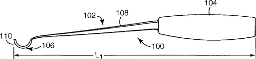
With reference to Fig. 8-10, it shows alternative additional embodiments of coating unit.Coating unit 100 comprises the application head 102 that is connected on the shank 104.In the illustrated embodiment, application head 102 and shank 104 constitute the integral type structure.Yet, be to be understood that in the optional embodiment of this device, application head 102 can remove from shank 104.
The application head 102 of device 100 comprises applicator 106 and the supporting member 108 with crooked end profile.Supporting member 108 is connected to application head 102 on the shank 104.In the illustrated embodiment, towards shank 104 convergents, and supporting member 108 comprises mesh-supported structure roughly triangular in shape to supporting member 108 from application head 102.The total length L of this device
1Be about 18 inches, and the overall width W of application head 102
1Be about 2 inches to 6 inches.Be to be understood that many other sizes and geometrical construction also are fine.
With reference to Figure 10-14, it has illustrated and has described in more detail the surface characteristics of application head 102.In the illustrated embodiment, the crooked end profile of applicator 106 is protruded with respect to surface to be coated.Applicator comprises the contact surface 110 that has groove, and this contact surface 110 is constructed to contact with surface to be coated.Groove among the embodiment that illustrates is parallel to each other and perpendicular to the width W of application head 102
1Be to be understood that other groove arrangement also are fine.
With reference to Figure 11, it illustrates the groove profile with triangular groove.The height h of this groove
1Be about 0.0004 inch to 0.4 inch, and the width S of groove
1Be about 0.02 inch to 0.07 inch.Figure 12 shows alternative other groove arrangement, and wherein this groove has rectangular profile and comprises the plane.Be to be understood that the jut between groove can also comprise that plane and/or this jut can be discontinuous.The height h of rectangular recess
2Be about 0.01 inch to 0.05 inch, and the width t of rectangular recess
2Be about 0.02 inch to 0.03 inch.The width t of jut
1Be about 0.02 inch to 0.03 inch, and from the center of a jut to the center of next jut apart from S
2Be about 0.01 inch to 0.1 inch.With reference to Figure 13, it illustrates another embodiment of the contact surface that has groove.In this embodiment that illustrates, groove is a U-shaped, and jut is a dome shape.The height h of U-shaped groove
3Be about 0.01 inch to 0.05 inch, and width t
6Be about 0.02 inch to 0.03 inch.The width t of jut
5Between about 0.02 inch to 0.03 inch, and from the center of a jut to the center of next jut apart from S
3Between about 0.01 inch to 0.1 inch.Figure 14 shows the embodiment that is similar to Figure 12 and the contact surface that has groove embodiment illustrated in fig. 13.The height h of groove
4Be about 0.01 inch to 0.05 inch, and the width t of groove
4Be about 0.02 inch to 0.03 inch.The width t of jut
3Between about 0.02 inch to 0.03 inch, and from the center of a jut to the center of next jut apart from S
4Between about 0.01 inch to 0.1 inch.Be to be understood that many other the optional embodiment that have the contact surface of groove are feasible, comprise the combination of the above-mentioned groove arrangement that illustrates and the arrangement of unshowned groove contact surface.
With reference to Figure 15 A-15E, it illustrates a plurality of end profile.When the below is watched, shown each end profile all is crooked and protrudes.Comprise consistent basically bending at the embodiment shown in Figure 15 A, wherein should bending can be described to have about 0.1875 inch radius of curvature R
1The embodiment shown in Figure 15 B comprise end portion with similar curvature, with and degree of crook less than the mid portion of any one end portion.Comprise end portion and the mid portion that has different curvature respectively at the embodiment shown in Figure 15 C.In the illustrated embodiment, end portion and mid portion almost are straight, but the overall shape of end profile is a convex.With reference to Figure 15 D, mid portion and an end portion have similar curvature R
2, this curvature is less than the curvature R of another end portion
3With reference to Figure 15 E, whole end profile has similar curvature R
4, this curvature is relatively large.In the illustrated embodiment, curvature R
4Be about 3 inches to 5 inches.Be to be understood that in optional embodiment, many other end profile are feasible.
With reference to Figure 16 A-16C, even illustrating schematic representation of apparatus, it is constructed to when shank 104 with respect to the horizontal plane becomes multiple different angle, also tool using effectively with explanation application head 102.Figure 16 A discloses with respect to the horizontal plane into about the 45 angle θ that spend
1Shank 104.Figure 16 B discloses with respect to the horizontal plane into about the 80 angle θ that spend
2Shank 104.Figure 16 C discloses with respect to the horizontal plane into about-5 angle θ that spend
3Shank 104.Even the device among the embodiment that illustrates is constructed to when the angular turn of shank is spent greater than 90, also can be so that about same section of the band groove surfaces of application head contacts with horizontal surface.In optional embodiment, even embodiment can be constructed to when the about 30-60 of the angular turn of shank spends, also can be so that about same section of the band groove surfaces of application head contacts with horizontal surface.
Be to be understood that although shown in the accompanying drawing only be several specific embodiments, each modification of each embodiment all within the scope of the invention.In addition, be to be understood that, can be incorporated in other embodiment and its modification or in conjunction with a described element of embodiment or feature and combine with other embodiment and its modification.
The application head of some embodiment is applicable to composition (for example, active compound) is coated on the surfaces such as floor 15 among Fig. 1 for example.Some embodiment of described application head are applicable to and apply the composition with highly filled (for example, solid of at least 40 weight %).Some embodiment of described application head are applicable to and apply the composition that dynamic viscosity is less than or equal to about 25,000 centipoises.Application head 35,75,106 can be used in the application system 10, and application system 10 comprises composition retainer 20 and coating unit 30.Be to be understood that in other optional embodiment, application head can be constructed to be suitable for having the composition of less solid by weight and/or have the composition of big dynamic viscosity.
The coating application system 10 that use has application head 35,75,106 preferably includes many compartments polybag or pouch, and so that each component is kept apart, this polybag or pouch have inner seal, and this inner seal can be easily and be controllably destroyed.Mix each component, can stave the internal partition between the pouch, and (for example) mixes each component by rubbing to press.From pouch, will distribute as the component through mixing of active compound.
A kind of preferred retainer 20, it is described in PCT patent disclosure WO2004/108404 to some extent also as allocation units simultaneously, and the full content of this invention is incorporated this paper into way of reference.This patent disclosure has also disclosed the various embodiments of many compartments polybag or pouch.
In case composition is distributed from retainer 20, just is easy to said composition for example is coated on the surface such as floor.Described surface generally can be any material, for example vinyl-based material, malthoid, pottery, plank, marble or the like.Application head 35,75,106 is providing suitable coating compounds on the smooth surface and on other surfaces porous or that have texture.
By using application head 35,75,106, be easy to apply active coating and be easy to form coating thin and that control easily, the streak of described coating, groove or other surface blemishes minimums.In some cases, only use application head 35,75,106 once just can obtain smooth and uniform coating.Application head 35,75,106 is particularly useful for the coating that coating thickness is not more than about 5 mils (about 127 microns) usually.In certain embodiments, different according to composition and coated surface, coated coating is that about 2 mils (about 51 microns) even about 1 mil (about 25 microns) are thick.Have highly filled composition,, can use application head 35,75,106 easily to apply for example greater than 40 weight % even greater than 50 weight %.Application head 35,75,106 can provide on rough surface has highly filled approaching and uniform coating.
In some cases, for example must be by cleaning, peeling off to remove previous coating and/or to prime to prepare surface to be coated.
Although above-mentioned argumentation is at using application head 35,75,106 on the floor, various other surfaces, for example wall, table top and framed bent, furniture and bathroom surfaces, all available described application head is coated with application layer.
The water base two parts polyurethane coating composition of example for forming of the active coating composition that use application head 35,75,106 is smeared and/or applied by two parts or bicomponent system.Such active compound can comprise the water-dispersible polyisocyanates component with ring diolatheapreferredachardasegment hardasegment component (for example, cyclohexanedimethanol) combination.For some compositions, preferred cyclohexanedimethanol is 1, the 4-cyclohexanedimethanol.Disclosed about being had in agent docket is the co-pending patent application of no.62026US002 (application number 11/423061) by other details of water-dispersible polyisocyanates component and the said composition that forms of ring diolatheapreferredachardasegment hardasegment, whole disclosures of this article are incorporated this paper into way of reference.
Be to be understood that, only be to use some examples of the suitable composition that application head of the present invention, coating unit and application system apply in this paper and the water base two parts polyurethane coating composition described in the co-pending patent application of agent docket no.62026US002 (application number 11/423061) and various feature thereof.Also can use other compositions.
Invention has been described in conjunction with various embodiment and technology.Yet, it is evident that to those skilled in the art, can carry out multiple variants and modifications to the present invention under the premise without departing from the spirit and scope of the present invention.
Claims (22)
1. one kind is used for liquid is coated to lip-deep instrument equably, and described instrument comprises:
Shank;
Application head, it is connected on the described shank, the lobed end profile of described application head,
The end profile of described projection has the contact surface that has groove;
Wherein said shank and application head are constructed to make that approximately the described contact surface that has groove of same amount contacts with described horizontal surface when described shank tilts with respect to the scope of horizontal surface between about 30 degree are spent to about 60.
2. instrument according to claim 1, wherein said shank and application head are constructed to make that approximately the described contact surface that has groove of same amount contacts with described horizontal surface when described shank tilts with respect to the scope of horizontal surface between about 10 degree are spent to about 80.
3. instrument according to claim 1, wherein said shank and application head are constructed to make that approximately the described contact surface that has groove of same amount contacts with described horizontal surface when described shank tilts with respect to the scope of horizontal surface between about 0 degree is spent to about 90.
4. instrument according to claim 1, the end profile of wherein said projection is with approximately constant radius of curvature bending.
5. instrument according to claim 4, wherein said radius of curvature is between about 0.1875 inch to 5.0 inches.
6. instrument according to claim 1, the wherein said contact surface that has groove have about 0.02 inch to 0.070 inch groove of being separated by from a center to another center at least.
7. instrument according to claim 1, the wherein said contact surface that has groove have about 0.02 inch to 0.03 inch high groove at least.
8. instrument according to claim 1, the wherein said contact surface that has groove comprises the groove with rectangular profile at least.
9. instrument according to claim 1, the wherein said contact surface that has groove comprises the groove with triangular-shaped profile at least.
10. instrument according to claim 1, the wherein said contact surface that has groove comprises the groove with dome-shaped profile at least.
11. instrument according to claim 1, the described liquid that the wherein said contact surface that has groove applies has the dynamic viscosity that is less than or equal to about 25000 centipoises.
12. one kind is used for liquid is applied to lip-deep instrument equably, described instrument comprises:
Application head, it is constructed to be connected on the shank, the lobed end profile of described application head, the end profile of described projection has the contact surface that has groove;
The wherein said contact surface that has groove comprises be separated by from a center to another center about 0.02 inch to 0.07 inch groove and about 0.02 inch to 0.03 inch high groove at least.
13. instrument according to claim 12, the wherein said contact surface that has groove comprises the groove with rectangular profile at least.
14. instrument according to claim 12, the wherein said contact surface that has groove comprises the groove with triangular-shaped profile at least.
15. instrument according to claim 12, the wherein said contact surface that has groove comprises the groove with dome-shaped profile at least.
16. instrument according to claim 12, wherein said application head are constructed so that approximately the described contact surface that has groove of same amount contacts with horizontal surface when described application head is spent at least about 30 with respect to described horizontal surface rotation.
17. instrument according to claim 12, wherein said application head are constructed so that approximately the described contact surface that has groove of same amount contacts with horizontal surface when described application head is spent at least about 70 with respect to described horizontal surface rotation.
18. instrument according to claim 12, wherein said application head are constructed so that approximately the described contact surface that has groove of same amount contacts with horizontal surface when described application head is spent at least about 90 with respect to described horizontal surface rotation.
19. instrument according to claim 12, the width of wherein said application head is between about 2 inches to 24 inches.
20. instrument according to claim 12, the radius of curvature of the groove on the wherein said contact surface that has a groove is less than about 4 inches.
21. instrument according to claim 12, the wherein said contact surface that has groove comprises polymer architecture.
22. instrument according to claim 12, the described liquid that the wherein said contact surface that has groove applies has the dynamic viscosity that is less than or equal to about 25000 centipoises.
Applications Claiming Priority (2)
| Application Number | Priority Date | Filing Date | Title |
|---|---|---|---|
| US80423306P | 2006-06-08 | 2006-06-08 | |
| US60/804,233 | 2006-06-08 |
Publications (1)
| Publication Number | Publication Date |
|---|---|
| CN101460689A true CN101460689A (en) | 2009-06-17 |
Family
ID=38564448
Family Applications (1)
| Application Number | Title | Priority Date | Filing Date |
|---|---|---|---|
| CNA2007800208493A Pending CN101460689A (en) | 2006-06-08 | 2007-06-04 | Applicator for floor coatings, and methods |
Country Status (10)
| Country | Link |
|---|---|
| US (1) | US20100275401A1 (en) |
| EP (1) | EP2032776A1 (en) |
| JP (1) | JP2009539585A (en) |
| KR (1) | KR20090026272A (en) |
| CN (1) | CN101460689A (en) |
| BR (1) | BRPI0711494A2 (en) |
| CA (1) | CA2654227A1 (en) |
| MX (1) | MX2008015596A (en) |
| TW (1) | TW200809062A (en) |
| WO (1) | WO2007146635A1 (en) |
Cited By (3)
| Publication number | Priority date | Publication date | Assignee | Title |
|---|---|---|---|---|
| CN103967261A (en) * | 2014-04-09 | 2014-08-06 | 上海大学 | Stain-resistant putty spatula and manufacturing method thereof |
| CN104736256A (en) * | 2012-06-25 | 2015-06-24 | 3M创新有限公司 | Devices for coating contoured surfaces |
| CN106988517A (en) * | 2017-03-14 | 2017-07-28 | 余文煜 | A kind of device of drawing limitation cement paved surface |
Families Citing this family (4)
| Publication number | Priority date | Publication date | Assignee | Title |
|---|---|---|---|---|
| US20070287824A1 (en) * | 2006-06-08 | 2007-12-13 | Johnson Mitchell T | Waterbased polyurethane floor coating composition |
| CA2734155A1 (en) | 2008-07-14 | 2010-01-21 | 3M Innovative Properties Company | Method of making a cleaning solution from hydrogel cleaning concentrate and packaged cleaning concentrate |
| EP2791267A4 (en) * | 2011-12-16 | 2015-05-20 | Mark Nolde | Surface cleaning and coating method and system |
| KR102033018B1 (en) | 2019-09-11 | 2019-11-08 | (주)7번가클린 | Floor cleaning and coating composition spreading device |
Family Cites Families (15)
| Publication number | Priority date | Publication date | Assignee | Title |
|---|---|---|---|---|
| US1441922A (en) * | 1922-03-17 | 1923-01-09 | Ohio Varnish Company | Graining tool |
| US3119138A (en) | 1962-01-11 | 1964-01-28 | Earl K Davis | Spreader for viscous materials |
| US3594244A (en) * | 1967-05-22 | 1971-07-20 | Exxon Research Engineering Co | Method of making an embossing structure |
| US3843992A (en) * | 1973-05-07 | 1974-10-29 | Murray Black Co Inc | Wood graining tool |
| SE8306247D0 (en) | 1983-11-14 | 1983-11-14 | Totalinstallation I Goteborg A | DEVICE FOR PREVENTING A FRESH CONCRETE SURFACE |
| DE3702374A1 (en) | 1987-01-27 | 1988-08-04 | Thomas Rinberger | Round-arch plasterer's float |
| US5778482A (en) | 1994-08-05 | 1998-07-14 | Sbrigato; Charles | Spreader for cold-coat roofing tar |
| US5937628A (en) * | 1997-09-19 | 1999-08-17 | Matechuk; William | Manually operable spreading apparatus for flowable materials |
| EP1072734B1 (en) | 1999-07-30 | 2007-05-30 | Roydon Charles Southby | Adhesive spreader |
| DE20208369U1 (en) | 2002-05-29 | 2002-08-08 | Fitterer Christian | Device for applying a material to a surface |
| US7111353B2 (en) * | 2003-04-18 | 2006-09-26 | Cowdery Dean J | Applicator |
| KR20060027319A (en) * | 2003-06-05 | 2006-03-27 | 쓰리엠 이노베이티브 프로퍼티즈 컴파니 | Plastic container with rupturable seal |
| EP1678395B1 (en) | 2003-10-31 | 2008-01-16 | Giovanni Fascianella | Device for spreading adhesive |
| US20070287824A1 (en) * | 2006-06-08 | 2007-12-13 | Johnson Mitchell T | Waterbased polyurethane floor coating composition |
| US7891041B2 (en) * | 2007-08-17 | 2011-02-22 | 3M Innovative Properties Company | Device for applying a uniform coating of floor finish |
-
2007
- 2007-06-04 MX MX2008015596A patent/MX2008015596A/en not_active Application Discontinuation
- 2007-06-04 CN CNA2007800208493A patent/CN101460689A/en active Pending
- 2007-06-04 CA CA002654227A patent/CA2654227A1/en not_active Abandoned
- 2007-06-04 WO PCT/US2007/070310 patent/WO2007146635A1/en active Application Filing
- 2007-06-04 US US12/303,308 patent/US20100275401A1/en not_active Abandoned
- 2007-06-04 BR BRPI0711494-0A patent/BRPI0711494A2/en not_active IP Right Cessation
- 2007-06-04 EP EP07798060A patent/EP2032776A1/en not_active Withdrawn
- 2007-06-04 JP JP2009514486A patent/JP2009539585A/en not_active Withdrawn
- 2007-06-04 KR KR1020087029561A patent/KR20090026272A/en not_active Application Discontinuation
- 2007-06-07 TW TW096120571A patent/TW200809062A/en unknown
Cited By (6)
| Publication number | Priority date | Publication date | Assignee | Title |
|---|---|---|---|---|
| CN104736256A (en) * | 2012-06-25 | 2015-06-24 | 3M创新有限公司 | Devices for coating contoured surfaces |
| CN104736256B (en) * | 2012-06-25 | 2018-09-14 | 3M创新有限公司 | Device for coating contoured surface |
| CN103967261A (en) * | 2014-04-09 | 2014-08-06 | 上海大学 | Stain-resistant putty spatula and manufacturing method thereof |
| CN103967261B (en) * | 2014-04-09 | 2016-04-27 | 上海大学 | Cutter and preparation method thereof criticized by stain resistant putty |
| CN106988517A (en) * | 2017-03-14 | 2017-07-28 | 余文煜 | A kind of device of drawing limitation cement paved surface |
| CN106988517B (en) * | 2017-03-14 | 2020-08-18 | 襄阳路桥建设集团有限公司 | Stretching type device for limiting cement pavement surface |
Also Published As
| Publication number | Publication date |
|---|---|
| EP2032776A1 (en) | 2009-03-11 |
| KR20090026272A (en) | 2009-03-12 |
| BRPI0711494A2 (en) | 2012-02-14 |
| TW200809062A (en) | 2008-02-16 |
| WO2007146635A1 (en) | 2007-12-21 |
| MX2008015596A (en) | 2008-12-18 |
| JP2009539585A (en) | 2009-11-19 |
| CA2654227A1 (en) | 2007-12-21 |
| US20100275401A1 (en) | 2010-11-04 |
Similar Documents
| Publication | Publication Date | Title |
|---|---|---|
| CN101460689A (en) | Applicator for floor coatings, and methods | |
| US6099940A (en) | Selectively-activatible three-dimensional sheet material having multi-stage progressive activation to deliver a substance to a target surface | |
| US5480250A (en) | Dispenser with rigid open pore nib | |
| ES2306475T3 (en) | MATERIAL IN ACTIVABLE SHEETS SELECTIVELY TO DISPOSE AND DISPERSE A SUBSTANCE ON AN OBJECTIVE SURFACE. | |
| US8566998B2 (en) | Absorbent structures with integrated contact elements | |
| CA2644565C (en) | Flexible abrasive article | |
| US20180338600A1 (en) | Double-Sided Make-Up Applicator | |
| ES2750865T3 (en) | Consumer scrub item with stain release and method of preparing it | |
| CA2280444C (en) | Liquid coating applicator | |
| US20080075946A1 (en) | Layered Composite Material, And Corresponding Device For Application Of Cosmetics | |
| US20070169303A1 (en) | Paint tray attachment for roller brush | |
| CN100586334C (en) | Roller hub with cover and loading device | |
| US6444266B1 (en) | Building panel and manufacturing method thereof | |
| CN1832811B (en) | Applicator and coating assembly for applying coatings and method of using the same | |
| US6666606B2 (en) | Coating tool and storage container | |
| JP4195942B2 (en) | Abrasive | |
| US20060179595A1 (en) | Corner painting tool | |
| KR20190048620A (en) | Carrier unit having pumping space and cosmetic goods comprising the same | |
| JP4348088B2 (en) | Building board manufacturing equipment | |
| JP2024041311A (en) | Application container | |
| JP6992217B2 (en) | Coating tool and coating substance storage container with coating tool | |
| JPH09187718A (en) | Sponge for coating | |
| JP2006051495A (en) | Applicator | |
| JPS5980353A (en) | Coater for long body | |
| JPH04108559A (en) | Coating apparatus |
Legal Events
| Date | Code | Title | Description |
|---|---|---|---|
| C06 | Publication | ||
| PB01 | Publication | ||
| C10 | Entry into substantive examination | ||
| SE01 | Entry into force of request for substantive examination | ||
| C02 | Deemed withdrawal of patent application after publication (patent law 2001) | ||
| WD01 | Invention patent application deemed withdrawn after publication |
Application publication date: 20090617 |