CN101360637A - Energy absorbing vehicle fender - Google Patents
Energy absorbing vehicle fender Download PDFInfo
- Publication number
- CN101360637A CN101360637A CNA2006800510262A CN200680051026A CN101360637A CN 101360637 A CN101360637 A CN 101360637A CN A2006800510262 A CNA2006800510262 A CN A2006800510262A CN 200680051026 A CN200680051026 A CN 200680051026A CN 101360637 A CN101360637 A CN 101360637A
- Authority
- CN
- China
- Prior art keywords
- shock absorber
- alignment portion
- vertical alignment
- flange
- fluctuating shape
- Prior art date
- Legal status (The legal status is an assumption and is not a legal conclusion. Google has not performed a legal analysis and makes no representation as to the accuracy of the status listed.)
- Pending
Links
Images


Classifications
-
- B—PERFORMING OPERATIONS; TRANSPORTING
- B62—LAND VEHICLES FOR TRAVELLING OTHERWISE THAN ON RAILS
- B62D—MOTOR VEHICLES; TRAILERS
- B62D25/00—Superstructure or monocoque structure sub-units; Parts or details thereof not otherwise provided for
- B62D25/08—Front or rear portions
- B62D25/16—Mud-guards or wings; Wheel cover panels
-
- B—PERFORMING OPERATIONS; TRANSPORTING
- B60—VEHICLES IN GENERAL
- B60R—VEHICLES, VEHICLE FITTINGS, OR VEHICLE PARTS, NOT OTHERWISE PROVIDED FOR
- B60R21/00—Arrangements or fittings on vehicles for protecting or preventing injuries to occupants or pedestrians in case of accidents or other traffic risks
- B60R21/34—Protecting non-occupants of a vehicle, e.g. pedestrians
-
- B—PERFORMING OPERATIONS; TRANSPORTING
- B62—LAND VEHICLES FOR TRAVELLING OTHERWISE THAN ON RAILS
- B62D—MOTOR VEHICLES; TRAILERS
- B62D29/00—Superstructures, understructures, or sub-units thereof, characterised by the material thereof
- B62D29/04—Superstructures, understructures, or sub-units thereof, characterised by the material thereof predominantly of synthetic material
- B62D29/043—Superstructures
-
- B—PERFORMING OPERATIONS; TRANSPORTING
- B60—VEHICLES IN GENERAL
- B60R—VEHICLES, VEHICLE FITTINGS, OR VEHICLE PARTS, NOT OTHERWISE PROVIDED FOR
- B60R21/00—Arrangements or fittings on vehicles for protecting or preventing injuries to occupants or pedestrians in case of accidents or other traffic risks
- B60R21/34—Protecting non-occupants of a vehicle, e.g. pedestrians
- B60R2021/343—Protecting non-occupants of a vehicle, e.g. pedestrians using deformable body panel, bodywork or components
Abstract
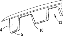
A fender (2) for absorbing forces generated from an impact includes a depending attachment flange which comprises a vertically aligned section (4) depending from an exterior portion of the fender and a horizontally aligned section (5) depending from the vertically aligned section (4) adapted for mounting to a vehicle wherein the vertically aligned section (4) includes a plurality of contoured portions (10) for enhancing the stiffness of the vertically aligned section.
Description
Related application
The application is the partial continuous application of U.S. Patent application PCT/US04/29279, and require in the U.S. Patent application PCT/US04/29279 of on September 3rd, 2004 application with in the preceence of the U.S. Provisional Application 60/500633 of application on September 5th, 2003 according to the 35th piece the 119th of United States Code, it all is herein incorporated with for referencial use.
Technical field
The present invention relates to a kind of vehicle shock absorber (fender) that is applicable to pedestrian protecting.
Background technology
The legislation in Japan and European countries futures may require a kind of endergonic design that is used for vehicle shock absorber system, to help to protect pedestrian's head and the collision that health is not subjected to automobile buffering device.
Typically, the metal buffer device is connected to the vehicle body of vehicle by rigid strutting piece, and this rigid pipe is called as sometimes forces plate (shotgun) or skirtboard.This rigid pipe that extends along longitudinal direction of car typically is connected to the framework of automobile, and forms the horizontally disposed skirtboard that is positioned under the hood, is used for the connection of shock absorber.A pair of rigid pipe is positioned on the sidepiece or engine bin of car front portion, to be used to be connected to corresponding shock absorber.The L shaped flange that forms the part of shock absorber protrudes in the front compartment, and is connected to the skirtboard of rigid pipe.The US Patent 6547316 of Chung is described a kind of protective device plate with impact absorption device, and its utilization is positioned at the curve under the hood, and this curve is connected between the skirtboard of the flange of shock absorber and strut member.The US Patent 6554341 of Lee relates to a kind of impact absorption device, and wherein the flange of shock absorber and the part between the skirtboard comprise from the outside and downward pair of leg of extending towards the skirtboard of strut member of shock absorber flange.' 316 patents comprise bent intermediate portion, and this curve is provided for absorbing energy to reduce his or her extent of injury when the collision pedestrian.
The scheme that is used for pedestrian protecting that proposes in the above-mentioned patent is to increase the flange of shock absorber and the distance between the rigid strutting piece and inserts independent, more weak structure relatively between the flange of shock absorber and rigid strutting piece.This independently weak structure can under the effect of relatively low power, be out of shape, to strengthen pedestrian protecting.Publication number: US2002/0060474A1 and US2003/0015890A1 relate generally to adamantine in essence metal buffer device.
Summary of the invention
The representative type shock absorber is relative to short distance to having between the connecting portion of rigid strutting piece or so-called pressure plate at the upper limb and the flange of this shock absorber.In order to observe following pedestrains safety requirement, particularly the head impact requirement of Ti Chuing, these zone existing problems of vehicle.In order to satisfy these requirements, wish the structure of the strut member of change shock absorber and shock absorber, make object relative less to set up intrusion interval (space), thereby make impact force reduce with the deceleration under the shock absorber collision.
According to embodiment, wish to increase the penetration distance of plastics shock absorber by the position that reduces rigid strutting piece or pressure plate.According to embodiment, the spatial stability of shock absorber is held, and shock absorber desired distortion under collision is provided simultaneously.Wish that shock absorber provides the reaction of proper level for invasiveness, in available deformation distance, to absorb collision strength power (energy force).According to embodiment, complete scheme is embodied in the thermoplastic material shock absorber, and it is suitable for pedestrains safety.According to embodiment, the deformable feature of shock absorber does not require extra part and non-productive operation.
According to embodiment, flange connector has vertical alignment portion, and it can be by tuning reducing the power from position collision on preceding when being impacted by object, but provides enough rigidity so that spatial stability to be provided on other direction.
According to embodiment, shock absorber is suitable for being connected to vehicle to absorb the power that collision produces.The flange connector that hangs (depending) comprises the vertical alignment portion of hanging from the outside of described shock absorber, and is connected at seam and from the horizontal alignment portion of vertical alignment portion suspension.This vertical alignment portion comprises a plurality of fluctuating shape parts, is used to strengthen the rigidity of vertical alignment portion, and wherein each fluctuating shape partly all is attached to vertical alignment portion and horizontal alignment flange part so that the rigidity of enhancing to be provided.
Proposed some variants in the literary composition, and can expect that difform a plurality of design feature can be incorporated in the vertical alignment portion of flange connector, to obtain the enough stability of expectation.
Description of drawings
Fig. 1 is the schematic side elevation of the shock absorber structure of prior art;
Fig. 2 is the schematic side elevation of the embodiment of shock absorber structure;
Fig. 3 is the part transparent view of an embodiment of the vertical alignment portion of flange connector;
Fig. 4 is the part transparent view of an embodiment of the vertical alignment portion of flange connector;
Fig. 5 is the part transparent view of an embodiment of the vertical alignment portion of flange connector;
Fig. 6 is the part transparent view of an embodiment of the vertical alignment portion of flange connector;
Fig. 7 is the part transparent view of an embodiment of the vertical alignment portion of flange connector;
Fig. 8 is the part transparent view of an embodiment of the vertical alignment portion of flange connector;
Fig. 9 is the part transparent view of an embodiment of the vertical alignment portion of flange connector;
Figure 10 is the part transparent view of an embodiment of the vertical alignment portion of flange connector;
Figure 11 is the part transparent view of an embodiment of the vertical alignment portion of flange connector;
Figure 12 is the part transparent view of an embodiment of the vertical alignment portion of flange connector;
Figure 13 is the part transparent view of an embodiment of the vertical alignment portion of flange connector;
Figure 14 is the part transparent view of an embodiment of the vertical alignment portion of flange connector;
Figure 15 is the part transparent view of an embodiment of the vertical alignment portion of flange connector.
The specific embodiment
Fig. 1 has shown the part viewgraph of cross-section that the typical prior art of metal buffer device 2 is installed, and this shock absorber 2 is fixed firmly to strut member 6 by the nuts and bolt shown in 7.Hood illustrates with reference number 1.Shock absorber 2 comprises flange part, and this flange part has the vertical hanging portion 4 that is connected to horizontal alignment portion 5.As shown in Figure 1, the height of vertical hanging portion 4 is shorter relatively, so the distance between the top of shock absorber 2 and the rigid strutting piece 6 is shorter relatively, thereby in collision process, before rigid strutting piece 6 is touched, provides a very little interval to invade for object.
Fig. 2 shows an embodiment, and wherein the height of the vertical alignment portion 4 of flange connector is enough to allow shock absorber distortion under collision, provides simultaneously from invading the gap of object to strut member 6.Shock absorber 2 comprises exterior trim face (exteriorly facing portion), and it has outside face attractive in appearance.Recess 3 extends downwardly in the front compartment (forward compartment) from outside face, and is provided for the seat of hood 1 when hood is in the closed position.Recess 3 comprises outward flange in the junction of itself and shock absorber 2.The flange connector portion of shock absorber 2 is installed to strut member 6 securely, and it typically provides the rigidity of shock absorber 2 to install.Strut member 6 is known in the prior art to be to force plate and metal construction and be installed to the framework of vehicle typically.This flange part comprises vertical alignment portion 4 and horizontal alignment portion 5, and vertical alignment portion 4 connects recess 3 along inward flange, and horizontal alignment portion 5 extends near strut member 6 to be connected to the there in front compartment.Vertical alignment portion 4 locates to be connected to horizontal alignment portion 5 in seam (juncture), to form flange connector (4,5).The horizontal alignment portion 5 of flange is installed to the horizontal alignment surface that matches of strut member 6.As shown in the figure, the fastener 7 of bolt form pass flange horizontal alignment portion 5 opening 8 and pass the skirtboard of strut member 6 or the hole in the horizontal alignment portion.Flange connector that this specification sheets is alleged or flange part comprise vertical alignment portion 4 and horizontal alignment portion 5.
According to an embodiment, shock absorber is a plastic material.The typical plastics material comprises the engineered thermoplastic material.The representative type thermoplastic base resin includes but not limited to polycarbonate (polycarbonates), copolyestercarbonates (copolyester carbonates), polyphenylene oxide (polyphenylene ethers), Polyurethane (polyurethanes), polyethylene (high or low density) polypropylene, flexible thermoplastic material etc., and the blend of they and other poly-mer, polycarbonate/polybutylene terephthalate (polybutylene terephthalate) for example, polyphenylene oxide/high impact polystyrene (high impactpolystyrene), polycarbonate/nitrile-butadiene-styrene (acryconitrile-butadiene-styrene) etc., and the blend of above-mentioned poly-mer.A kind of thermoplastic base resin is polycarbonate // polybutylene terephthalate composite, its by General Electric Company with trade mark XENOY
 Resin is sold.A kind of preferred thermoplastic material is the blend of polyphenylene oxide and polyamide, its by General ElectricCompany with trade name NORYL GTX
 Resin is sold.Comprise the filler of the fiber of glass for example and comprise that the compound of the Nano type of nanotube also can use with thermoplastic material.
Comprise being used to settle the recess 3 of hood and the whole shock absorber 2 of flange connector (4,5) to form single part by thermoplastic material ideally, this flange connector (4,5) is fixed to vehicle strut member 6 to shock absorber 2.The vertical alignment portion 4 of flange connector (4,5), it provides support for the outside of shock absorber 2, is suitable for distortion under predetermined collision, provides spatial stability for shock absorber 2 simultaneously between normal used life.Vertical alignment portion 4 has enough height or deformation distance, with rigid strutting piece 6 not by the situation of strong collision under deformable ground absorb collision.As shown in Figure 1, the vertical alignment portion of flange 4 forms walls, and this wall extends between the horizontal alignment portion 5 of recessed 3 inward flange and flange connector (4,5).This wall has the rigidity that specific fluctuating shape shape (contoured shape) provides enhancing, is approximately perpendicular to the power of the direction of this wall with the opposing edge.Fluctuating shape shape comprises the variant of protuberance or impression form, and its expectation is connected to or near horizontal alignment portion, resists along horizontal power so that rigidity to be provided.Preferred fluctuating shape part or variant 10 be attached to vertical alignment flange part 4 and horizontal alignment flange part 5 both.According to preferred embodiment, a plurality of fluctuating shape parts or variant 10 are spaced a predetermined distance under recessed 3 edge.Utilize this configuration, vertical alignment portion tends to make recessed 3 distortion that close on.In a preferred embodiment, fluctuating shape part 10 is used to strengthen flange and is the form of protuberance, and it extends between the vertical alignment portion 4 of the horizontal part of flange and flange.In a preferred embodiment, a plurality of enhancing portion is along the length setting of wall or vertical component effect.
The vertical dimension of the vertical alignment portion 4 of flange can change according to concrete vehicle, and preferably is equal to or greater than about 60 millimeters (mm).The height of preferred vertical alignment portion 4 is from about 60 to about 100 millimeters.According to the present invention, about 80 millimeters height is the representative type height.Preferably, at least a portion fluctuating shape part or variant 10 the height of the vertical alignment portion 4 of flange about 2/3rds on extend.Shape part of preferably rising and falling or variant 10 extend upward from the horizontal alignment portion 5 of flange.As mentioned above, fluctuating shape part 10 preferably is attached to vertical alignment portion 4 and horizontal alignment portion 5, to strengthen each one 4 with 5 combination or be connected.
During colliding, deformable wall is out of shape ideally to absorb collision energy.The energy absorption efficiency of variant is suitable for obtaining the rigidity of expecting for spatial stability and reduces impact force.By using the material and the geometric configuration of different densities or different-thickness, the collision response of vertical alignment portion 4 can be adjusted for particular vehicle.According to various embodiment, but the horizontal part of the height of the quantity of the shape of the energy that comes self collision by fluctuating shape part, variant, the variant measured from horizontal flanges, the width of variant, the degree of depth of variant, the variation that the thickness of opening or wall is set the vertical alignment portion 4 of flange, flange and have the variation of seam of protuberance of wall and Be Controlled.It is the energy that absorbs the particular crash level that one or more features can be changed to adjust shock absorber.Geometric configuration also can be dependent on space constraint or user's pattern or higher or lower available envelope space (package space).
As shown in Figure 3, fluctuating shape part 10 is the forms with multiaspect projection of pair of sidewalls and upper wall, and described upper wall connects from the isolated front wall portion of vertical wall of the vertical alignment portion 4 of flange.Fig. 4 shows the embodiment of Fig. 3, and its mesorelief shape part 10 comprises opening or otch 13.Fig. 5 shows the embodiment of Fig. 4, and wherein except the opening 13 in the fluctuating shape part 10, opening 15 is arranged in the vertical alignment portion 4 of flange.Fig. 6 shows the vertical alignment portion 4 of flange, and this flange has the fluctuating shape part 10 that even interval is provided with, and each fluctuating shape part 10 has opening 13.Fig. 7 show in fluctuating shape part 10 and the vertical component effect 4 of flange in use embodiment with difform opening 13.Fig. 8 shows the fluctuating shape part 10 with two joint flat surfaces that extend between vertical and horizontal part 4 and 5 in each of flange.This connection surface has hexagonal shape at the seam with flange, has two seams with the vertical alignment portion 4 of flange, has two seams with the horizontal alignment portion 5 of flange.Shown in structure in, each adjacent fluctuating shape part 10 also forms seam.Fig. 9 shows the fluctuating shape part with pair of intersecting plane, and this intersecting plane forms triangle in the intersection of each vertical alignment portion 4 and horizontal alignment portion 5.Figure 10 shows the modification of the fluctuating shape part of Fig. 9, and wherein clinoplane portion is positioned at this in the middle of the intersecting plane.Figure 11 shows the embodiment of Figure 10, and wherein different clinoplanes is used to form fluctuating shape part 10.Figure 11,12,13 and 15 shows the fluctuating shape part 10 of using various profiled surfaces.Such profiled surface can comprise ellipse, parabola shaped or other curved shape, and it can be symmetry or asymmetric.
Although it is evident that the preferred embodiments of the present invention that disclosed is suitably planned to realize described target, will be appreciated that the present invention allows not deviate from the modification of the spirit and scope of the present invention, variation and change, wherein the spirit and scope of the present invention are limited only by the accompanying claims.
Claims (16)
1. shock absorber, it is suitable for being connected to vehicle to absorb the power that collision produces, and described shock absorber comprises the flange connector of suspension,
Described flange connector comprises vertical alignment portion of hanging from the outside of described shock absorber and the horizontal alignment portion of hanging from this vertical alignment portion that engages at seam,
Described vertical alignment portion comprises a plurality of fluctuating shape parts, is used to strengthen the rigidity of described vertical alignment portion, and wherein each fluctuating shape part all is attached to described vertical alignment portion and described horizontal alignment flange part so that the rigidity of enhancing to be provided.
2. shock absorber as claimed in claim 1, the vertical dimension of the vertical alignment portion of wherein said flange are equal to or greater than about 60 millimeters.
3. shock absorber as claimed in claim 1, the height of wherein said vertical alignment portion is about 60 millimeters to about 100 millimeters.
4. shock absorber as claimed in claim 1, wherein the described fluctuating shape part of at least a portion is extended on about 2/3rds height of the vertical alignment portion of described flange.
5. shock absorber as claimed in claim 1, it is suitable for cooperating with hood, and wherein said shock absorber comprises: the exterior trim face, described exterior trim face has outside face attractive in appearance; Recess, described recess leaves from described outside face attractive in appearance extension, to be provided for the seat of described hood when described hood is in the closed position.
6. shock absorber as claimed in claim 1, described vertical alignment portion is connected to described horizontal alignment portion to form described flange connector at seam.
7. shock absorber as claimed in claim 1, it is suitable for being installed on the vehicle strut member, and the described horizontal alignment portion of wherein said flange is adapted to fasten to the horizontal alignment surface that matches of described strut member.
8. shock absorber as claimed in claim 1, wherein said shock absorber all is made up of plastic material basically.
9. shock absorber as claimed in claim 1, wherein said shock absorber all is made up of thermoplastic material basically.
10. shock absorber as claimed in claim 1, wherein said shock absorber all is made up of the plastic material of selecting the group of forming from polycarbonate, copolyestercarbonates, polyphenylene oxide, Polyurethane, polyethylene and polypropylene basically.
11. shock absorber as claimed in claim 1, wherein said shock absorber all are made up of the blend of the plastic material of selecting the group of forming from polycarbonate/polybutylene terephthalate blend, polyphenylene oxide/high impact polystyrene blend, polycarbonate/nitrile-butadiene-styrene blend and their blend basically.
12. shock absorber as claimed in claim 1, the vertical alignment portion of wherein said flange connector is suitable for being out of shape under predetermined collision, and provides spatial stability for described shock absorber between normal used life.
13. shock absorber as claimed in claim 1, wherein said vertical alignment portion comprises at least one fluctuating shape part, thinks that described vertical alignment portion provides the rigidity of enhancing and opposing along horizontal power.
14. shock absorber as claimed in claim 1, wherein said fluctuating shape part extends upward from the horizontal alignment portion of described flange.
15. shock absorber as claimed in claim 1, wherein said fluctuating shape partly comprises opening, and this opening is used to reduce the rigidity of described fluctuating shape part.
16. shock absorber according to claim 1, it is suitable for being connected to vehicle to absorb the power that collision produces, and described shock absorber comprises the single integral unit of molded thermoplastic material.
Applications Claiming Priority (2)
| Application Number | Priority Date | Filing Date | Title |
|---|---|---|---|
| US11/273,104 | 2005-11-14 | ||
| US11/273,104 US7192080B2 (en) | 2003-09-05 | 2005-11-14 | Energy absorbing vehicle fender |
Publications (1)
| Publication Number | Publication Date |
|---|---|
| CN101360637A true CN101360637A (en) | 2009-02-04 |
Family
ID=37813636
Family Applications (1)
| Application Number | Title | Priority Date | Filing Date |
|---|---|---|---|
| CNA2006800510262A Pending CN101360637A (en) | 2005-11-14 | 2006-11-01 | Energy absorbing vehicle fender |
Country Status (7)
| Country | Link |
|---|---|
| US (1) | US7192080B2 (en) |
| EP (1) | EP1948487A1 (en) |
| JP (1) | JP2009515772A (en) |
| KR (1) | KR20080080108A (en) |
| CN (1) | CN101360637A (en) |
| AU (1) | AU2006315835A1 (en) |
| WO (1) | WO2007058786A1 (en) |
Cited By (1)
| Publication number | Priority date | Publication date | Assignee | Title |
|---|---|---|---|---|
| CN110126601A (en) * | 2018-02-09 | 2019-08-16 | 丰田自动车株式会社 | Front part structure of vehicle |
Families Citing this family (8)
| Publication number | Priority date | Publication date | Assignee | Title |
|---|---|---|---|---|
| EP1449749A1 (en) * | 2003-02-12 | 2004-08-25 | Compagnie Plastic Omnium | Car fender support |
| FR2866622B1 (en) * | 2004-02-24 | 2006-05-19 | Inoplast Sa | INTERMEDIATE ELEMENT FOR SUPPORTING A FRONT FENDER OF A MOTOR VEHICLE AND METHOD FOR MANUFACTURING THE SAME |
| EP1892162A3 (en) * | 2006-08-21 | 2009-12-02 | Alutech Gesellschaft m.b.H. | Pedestrian protection for a motor vehicle |
| DE602007008098D1 (en) * | 2007-09-10 | 2010-09-09 | Ford Global Tech Llc | Pedestrian safety device for a motor vehicle body |
| DE102008010138A1 (en) * | 2008-02-20 | 2009-08-27 | Dr. Ing. H.C. F. Porsche Aktiengesellschaft | mudguard assembly |
| US9783152B2 (en) * | 2011-10-11 | 2017-10-10 | GM Global Technology Operations LLC | Vehicle impact reduction structure |
| US9650003B2 (en) | 2014-07-02 | 2017-05-16 | GM Global Technology Operations LLC | Impact resistant component for a vehicle |
| DE102014118180A1 (en) | 2014-12-09 | 2016-06-09 | Dr. Ing. H.C. F. Porsche Aktiengesellschaft | Assembly for mounting a fender in a non-structural carrier in a motor vehicle |
Family Cites Families (10)
| Publication number | Priority date | Publication date | Assignee | Title |
|---|---|---|---|---|
| US5171058A (en) * | 1989-06-30 | 1992-12-15 | Mazda Motor Corporation | Collision energy absorbing structure for a vehicle side body |
| DE4401023C1 (en) * | 1994-01-15 | 1995-03-16 | Daimler Benz Ag | Motor vehicle forepart |
| JP2001310767A (en) * | 2000-04-27 | 2001-11-06 | Mazda Motor Corp | Structure for vehicle front part |
| KR100387886B1 (en) * | 2000-11-20 | 2003-06-18 | 현대자동차주식회사 | Fender panel impact absorption structure with walker protection function in car |
| DE10102187A1 (en) * | 2001-01-16 | 2002-08-01 | Volkswagen Ag | Impact damping mudguard for a vehicle comprises a support element which is made of a hard, almost inflexible material, and is divided by a fold line into two sections forming an obtuse angle |
| JP4762438B2 (en) * | 2001-05-18 | 2011-08-31 | 富士重工業株式会社 | Front body structure of the vehicle |
| KR100412838B1 (en) * | 2001-07-21 | 2003-12-31 | 현대자동차주식회사 | fender part structure for automotive vehicle |
| JP4192452B2 (en) * | 2001-09-18 | 2008-12-10 | トヨタ自動車株式会社 | Vehicle fender structure |
| JP3838125B2 (en) * | 2002-03-15 | 2006-10-25 | 日産自動車株式会社 | Fender structure |
| AU2004270729A1 (en) * | 2003-09-05 | 2005-03-17 | Sabic Innovative Plastics Ip B.V. | Energy absorbing vehicle fender |
-
2005
- 2005-11-14 US US11/273,104 patent/US7192080B2/en active Active
-
2006
- 2006-11-01 WO PCT/US2006/042854 patent/WO2007058786A1/en active Application Filing
- 2006-11-01 CN CNA2006800510262A patent/CN101360637A/en active Pending
- 2006-11-01 AU AU2006315835A patent/AU2006315835A1/en not_active Abandoned
- 2006-11-01 JP JP2008541204A patent/JP2009515772A/en not_active Withdrawn
- 2006-11-01 KR KR1020087013513A patent/KR20080080108A/en not_active Application Discontinuation
- 2006-11-01 EP EP06844253A patent/EP1948487A1/en not_active Withdrawn
Cited By (2)
| Publication number | Priority date | Publication date | Assignee | Title |
|---|---|---|---|---|
| CN110126601A (en) * | 2018-02-09 | 2019-08-16 | 丰田自动车株式会社 | Front part structure of vehicle |
| CN110126601B (en) * | 2018-02-09 | 2022-07-08 | 丰田自动车株式会社 | Vehicle front structure |
Also Published As
| Publication number | Publication date |
|---|---|
| KR20080080108A (en) | 2008-09-02 |
| AU2006315835A1 (en) | 2007-05-24 |
| US20060113825A1 (en) | 2006-06-01 |
| EP1948487A1 (en) | 2008-07-30 |
| WO2007058786A1 (en) | 2007-05-24 |
| JP2009515772A (en) | 2009-04-16 |
| US7192080B2 (en) | 2007-03-20 |
Similar Documents
| Publication | Publication Date | Title |
|---|---|---|
| CN101360638A (en) | Energy absorbing vehicle fender | |
| CN101360637A (en) | Energy absorbing vehicle fender | |
| US7204545B2 (en) | Fender support for a motor vehicle | |
| CN101360636A (en) | Energy absorbing vehicle fender | |
| US6994384B2 (en) | Integrated solitary bumper beam | |
| JP2008526590A (en) | Bumper system with energy absorber | |
| JP2008513260A (en) | Bumper assembly including energy absorbing member with vertical translational crush lobe | |
| US20070029840A1 (en) | Energy absorbing vehicle fender | |
| JP2000203362A (en) | Shock energy absorbing device for body upper part of automobile | |
| CN202243325U (en) | Pedestrian protection device for vehicle | |
| US20090039676A1 (en) | Vacuum-formed "firm-feel" reinforcement for bumper fascias | |
| CN110087975A (en) | Motor vehicles rear structure including the reinforcer for rear impact | |
| CN102897137A (en) | Pedestrian protection device for automobile | |
| CN110816463B (en) | A ventilation grid fixed bolster and vehicle for vehicle | |
| CN113619363A (en) | Foam energy absorber for automobile door guard board | |
| JP2006123812A (en) | Mounting structure of seat belt anchor | |
| KR101154697B1 (en) | Front bumper beam of vehicle | |
| JP2001354092A (en) | Pillar for automobile | |
| KR19980015902A (en) | Buffer-reinforced impact beam for automotive bumpers |
Legal Events
| Date | Code | Title | Description |
|---|---|---|---|
| C06 | Publication | ||
| PB01 | Publication | ||
| C41 | Transfer of patent application or patent right or utility model | ||
| TA01 | Transfer of patent application right |
Effective date of registration: 20090116 Address after: Bergen Op Zoom Holland Applicant after: Sabic Innovative Plastics Ip Address before: American New York Applicant before: General Electric Company |
|
| ASS | Succession or assignment of patent right |
Owner name: SHABO BASE CREATION PLASTICS INTELLECTUAL PROPERTY Free format text: FORMER OWNER: GENERAL ELECTRIC CO. Effective date: 20090116 |
|
| C10 | Entry into substantive examination | ||
| SE01 | Entry into force of request for substantive examination | ||
| C02 | Deemed withdrawal of patent application after publication (patent law 2001) | ||
| WD01 | Invention patent application deemed withdrawn after publication |
Open date: 20090204 |