CN101358997A - Inspection jig and inspection equipment - Google Patents
Inspection jig and inspection equipment Download PDFInfo
- Publication number
- CN101358997A CN101358997A CNA2008101441557A CN200810144155A CN101358997A CN 101358997 A CN101358997 A CN 101358997A CN A2008101441557 A CNA2008101441557 A CN A2008101441557A CN 200810144155 A CN200810144155 A CN 200810144155A CN 101358997 A CN101358997 A CN 101358997A
- Authority
- CN
- China
- Prior art keywords
- probe
- mentioned
- rear end
- end side
- inserting hole
- Prior art date
- Legal status (The legal status is an assumption and is not a legal conclusion. Google has not performed a legal analysis and makes no representation as to the accuracy of the status listed.)
- Pending
Links
Images


Classifications
-
- G—PHYSICS
- G01—MEASURING; TESTING
- G01R—MEASURING ELECTRIC VARIABLES; MEASURING MAGNETIC VARIABLES
- G01R1/00—Details of instruments or arrangements of the types included in groups G01R5/00 - G01R13/00 and G01R31/00
- G01R1/02—General constructional details
- G01R1/06—Measuring leads; Measuring probes
- G01R1/067—Measuring probes
- G01R1/073—Multiple probes
-
- G—PHYSICS
- G01—MEASURING; TESTING
- G01R—MEASURING ELECTRIC VARIABLES; MEASURING MAGNETIC VARIABLES
- G01R1/00—Details of instruments or arrangements of the types included in groups G01R5/00 - G01R13/00 and G01R31/00
- G01R1/02—General constructional details
- G01R1/04—Housings; Supporting members; Arrangements of terminals
-
- G—PHYSICS
- G01—MEASURING; TESTING
- G01R—MEASURING ELECTRIC VARIABLES; MEASURING MAGNETIC VARIABLES
- G01R1/00—Details of instruments or arrangements of the types included in groups G01R5/00 - G01R13/00 and G01R31/00
- G01R1/02—General constructional details
- G01R1/06—Measuring leads; Measuring probes
- G01R1/067—Measuring probes
- G01R1/06711—Probe needles; Cantilever beams; "Bump" contacts; Replaceable probe pins
- G01R1/06716—Elastic
-
- G—PHYSICS
- G01—MEASURING; TESTING
- G01R—MEASURING ELECTRIC VARIABLES; MEASURING MAGNETIC VARIABLES
- G01R31/00—Arrangements for testing electric properties; Arrangements for locating electric faults; Arrangements for electrical testing characterised by what is being tested not provided for elsewhere
- G01R31/26—Testing of individual semiconductor devices
- G01R31/2601—Apparatus or methods therefor
-
- G—PHYSICS
- G01—MEASURING; TESTING
- G01R—MEASURING ELECTRIC VARIABLES; MEASURING MAGNETIC VARIABLES
- G01R31/00—Arrangements for testing electric properties; Arrangements for locating electric faults; Arrangements for electrical testing characterised by what is being tested not provided for elsewhere
- G01R31/50—Testing of electric apparatus, lines, cables or components for short-circuits, continuity, leakage current or incorrect line connections
Abstract
The invention provides a check clamp. Even if transverse amplitude for forming a long narrow terminal for checking is quite narrow, the check clamp can check a checked object definitely. The check clamp (1) for checking the checked object (50) comprising a longitudinal long narrow terminal and a transverse long narrow terminal is provided with a front end support body (2) with a front end inserting through hole, a back end support body (3) arranged correspondingly to the front end support body (2) through clearance and provided with a back end inserting through hole, and a probe (5) inserted in the front end part of the front end inserting through hole and the back end part of the back end inserting through hole, wherein, the front end inserting through hole has a probe guiding direction towards the checked object (50), and the back end inserting through hole has a probe guiding direction inclined along the longitudinal direction of the terminal relatively to the probe guiding direction of the front end inserting through hole; the front end part of the probe (5) is arranged relatively to the back end part at a position shifting on one side inclining the probe guiding direction of the back end inserting through hole.
Description
Technical field
What the present invention relates to is to use in the gauging fixture of the electric checking of circuit board or electron device etc. and the testing fixture that is provided with this gauging fixture.
Background technology
Generally speaking, be used for finding the electric checking of the abnormal conditions such as short circuit, broken string of integrated circuit such as the wiring figure of circuit board or IC, use to be provided with and to be formed at the inspection of checking object with the be conductively connected gauging fixture of a plurality of probes of touching of terminal.As this gauging fixture, the applicant has proposed to be provided with the gauging fixture of front supporter, rear end side supporter and electrode, wherein, the front part of a plurality of probes of front support body supports, the rear end side supporter is disposed at the rear of front supporter by the gap and supports the rear end side part of a plurality of probes, electrode is disposed at the rear of rear end side supporter and partly join with the rear end side of probe (for example, with reference to patent documentation 1).
In the gauging fixture of this patent documentation 1 record, on the front supporter, be vertically intersected on the direction of checking the opposed faces that object is relative on be formed with the front inserting hole; On the rear end side supporter, on the direction that the formation direction with respect to the front inserting hole tilts, be formed with the rear end side inserting hole.In addition, the rear end side inserting hole leads in the front of the probe of this rear end side inserting hole towards the front inserting hole as inserting, and tilts with respect to the front inserting hole.
In this gauging fixture, when the front end of a plurality of probes joins with the inspection object, be disposed at the probe center section bending in the gap between front supporter and the rear end side supporter.In addition, by the center section bending of probe, whole probes contacts with the inspection object simultaneously with the contact pressure of appropriateness.
Patent documentation 1: day disclosure communique, spy open 2005-338065 number
Summary of the invention
Invent problem to be solved
In recent years, be formed at the inspection of checking object with terminal variation.For example, checking the elongate terminal that also is formed with on the object as rectangle.In addition, be accompanied by the highly integrated etc. of the complicated or integrated circuit that becomes the circuit board wiring figure of checking object in recent years, the horizontal amplitude of elongate terminal becomes very narrow.For example, having horizontal amplitude is that the terminal of the so very narrow amplitude of 20 μ m~30 μ m is formed at the situation of checking object.
At this, research by the present application people is clear and definite, under the situation that the gauging fixture of record is checked the very narrow inspection object of the horizontal amplitude of terminal in using patent documentation 1, exist checking that object carries out the danger that definite inspection becomes difficulty.
Therefore, it is a kind of that problem of the present invention is to provide, even under the inspection that the forms elongate situation very narrow with the horizontal amplitude of terminal, and also can be to the testing fixture of checking that object carries out the gauging fixture of definite inspection and is provided with this gauging fixture.
Solve the means of problem
In order to solve above-mentioned problem, gauging fixture of the present invention, be to be used for gauging fixture that the inspection object that is formed with the elongate terminal that possesses vertical and horizontal is checked, it is characterized in that, be provided with: the front supporter that is formed with the front inserting hole, dispose by predetermined gap with respect to the front supporter, and be formed with the rear end side supporter of rear end side inserting hole, and probe, wherein, the front inserting hole has towards the probe channeling direction of checking object, the rear end side inserting hole has with respect to the probe channeling direction of front inserting hole along the longitudinal and the probe channeling direction that tilts, and probe has to be inserted and leads in the front part of front inserting hole and inserted the rear end side part of leading in the rear end side inserting hole, so that can check subject side discrepancy with the front end of termination contact; The front part of probe partly is disposed at respect to rear end side, the position that is offset on the side that the probe channeling direction of distolateral inserting hole tilts backward.
In gauging fixture of the present invention, on the rear end side supporter that disposes by predetermined gap with respect to the front supporter that is formed with the front inserting hole, be formed with the rear end side inserting hole, wherein, the front inserting hole has towards the probe channeling direction of checking object, the rear end side inserting hole have with respect to the probe channeling direction of front inserting hole along the elongate terminal vertically and the probe channeling direction that tilts.In addition, the front of probe part partly is disposed at respect to rear end side, the position that is offset on the side that the probe channeling direction of distolateral inserting hole tilts backward.
Therefore, even can be for the front end that makes probe under the front inserting hole forms than the big situation of the diameter of probe checking subject side to come in and go out, the front end of probe and termination contact and be disposed at the center section bending of the probe in the gap between front supporter and the rear end side supporter, front part vertically moving along the elongate terminal in the front inserting hole of probe.That is to say, among the present invention, be disposed at the center section of the probe in the gap between front supporter and the rear end side supporter in the front end of probe and termination contact when crooked, with the front end of the probe of termination contact along vertically being offset of terminal, and not too have along the situation of the lateral excursion of terminal.Consequently, among the present invention, even under the inspection that the forms elongate situation very narrow with the horizontal amplitude of terminal, the front end that also can make probe positively with the termination contact of checking object, thereby can be to checking that object carry out definite inspection.
In the present invention, be provided with respectively a plurality of probes with vertically different a plurality of termination contact with gauging fixture, the rear end side part of a plurality of probes by insert lead in along terminal that each probe contacted vertically and the rear end side inserting hole that tilts is good.Constitute like this, even checking under the situation that is formed with vertically different a plurality of terminals on the object, the front end that also can make probe positively with the termination contact of checking object, thereby can be to checking that object carry out definite inspection.
In addition, in order to solve above-mentioned problem, the present invention is used for gauging fixture that the inspection object that is formed with the elongate terminal that possesses vertical and horizontal is checked, it is characterized in that, be provided with: the front supporter that is formed with the front inserting hole, be formed with the rear end side inserting hole, and the rear end side supporter that disposes by predetermined gap with respect to the front supporter, and has a front end with termination contact, inserted to lead to and led in the probe of the rear end side part of rear end side inserting hole in the front part of front inserting hole and by slotting, wherein, the front inserting hole has towards the probe channeling direction of checking object, and the rear end side inserting hole has the probe channeling direction with respect to the front inserting hole, along by vertically and the plane that forms of the probe channeling direction of front inserting hole and the probe channeling direction that tilts; When front end and termination contact, front end is pressed into towards the front supporter, and simultaneously, probe is crooked between front supporter and rear end side supporter.
In gauging fixture of the present invention, on the rear end side supporter that disposes by predetermined gap with respect to the front supporter that is formed with the front inserting hole, be formed with the rear end side inserting hole, wherein, the front inserting hole has towards the probe channeling direction of checking object, the rear end side inserting hole have probe channeling direction with respect to the front inserting hole, along by the elongate terminal vertically and the plane that forms of the probe channeling direction of front inserting hole and the probe channeling direction that tilts.Therefore, even for its front end is pressed into and under the front inserting hole forms than the big situation of the diameter of probe towards the front supporter, the front end of probe and termination contact and words that probe bends between front supporter and rear end side supporter, the front end of probe is also along the vertical misalignment of terminal, and not too has along the situation of the lateral excursion of terminal.Consequently, among the present invention, even under the inspection that the forms elongate situation very narrow with the horizontal amplitude of terminal, the front end that also can make probe positively with the termination contact of checking object, thereby can be to checking that object carry out definite inspection.
Gauging fixture of the present invention can be used in and be provided with the testing fixture that is connected in the electric checking portion of the electrode that partly joins with the probe rear end side by conduction.This testing fixture, even under the inspection that the forms elongate situation very narrow with the horizontal amplitude of terminal, the front end that also can make probe positively with the termination contact of checking object, thereby can be to checking that object carry out definite inspection.
The invention effect
As mentioned above, gauging fixture of the present invention and testing fixture, even under the inspection that the forms elongate situation very narrow with the horizontal amplitude of terminal, also can be to checking that object carry out definite inspection.
Description of drawings
Fig. 1 is the vertical view of the gauging fixture that relates to of the invention process form.
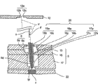
Fig. 2 is the outboard profile of gauging fixture shown in Figure 1.
Fig. 3 is the vertical view of the inspection object checked with gauging fixture shown in Figure 1 of expression.
Fig. 4 is the enlarged drawing that the E portion of Fig. 3 is amplified expression.
Fig. 5 is the amplification profile of the profile construction of expression front supporter shown in Figure 1.
Fig. 6 is the amplification profile of the profile construction of expression rear end side supporter shown in Figure 1.
Fig. 7 is the summary pie graph that expression is equipped with the testing fixture of gauging fixture shown in Figure 1.
Fig. 8 is the figure that is used to illustrate the probe action when checking object with testing fixture inspection shown in Figure 7, (A) from the front end of the horizontal expression probe of terminal and the state before the termination contact, (B) from the front end of the horizontal expression probe of terminal and the state of termination contact, (C) from the front end of vertical expression probe of terminal and the state of termination contact.
Fig. 9 is the synoptic diagram that the terminal of the inspection object that relates to of other examples of the present invention is arranged.
Figure 10 is the synoptic diagram that the terminal of the inspection object that relates to of other examples of the present invention is arranged.
Figure 11 is the synoptic diagram of the shape of the terminal that relates to of other examples of the present invention.
Symbol description
1 gauging fixture
2 front supporters
3 rear end side supporters
5 probes
5c front part
5d rear end side part
The 5e front end
7 electrodes
13 front inserting holes
20 rear end side inserting holes
30 testing fixtures
31 control parts (electric checking portion)
50 check object
60,61,62,63 terminals
V probe channeling direction
Embodiment
Below, with reference to the accompanying drawings example of the present invention is described.
(formation of gauging fixture)
Fig. 1 is the vertical view of the gauging fixture 1 that relates to of the invention process form.Fig. 2 is the outboard profile of gauging fixture 1 shown in Figure 1.Fig. 3 is the vertical view of the inspection object 50 checked with gauging fixture 1 shown in Figure 1 of expression.Fig. 4 is the enlarged drawing that the E portion of Fig. 3 is amplified expression.Fig. 5 is the amplification profile of the profile construction of expression front supporter 2 shown in Figure 1.Fig. 6 is the amplification profile of the profile construction of expression rear end side supporter 3 shown in Figure 1.
In addition, in the following description, with the left and right directions of Fig. 1 as the above-below direction of directions X, Fig. 1 as the paper vertical direction of Y direction, Fig. 1 as the Z direction.In addition, the plane that forms as YZ plane, Z direction and directions X, the plane that will be formed by Y direction and Z direction is as the ZX plane.
The gauging fixture 1 of this form is as described below, and the inspection object 50 that is equipped on printed-wiring board (PWB) or SIC (semiconductor integrated circuit) etc. carries out the testing fixture 30 of electric checking and is used (with reference to Fig. 7).In addition, the gauging fixture 1 of this form as shown in Figure 3, Figure 4, is to be used for checking the anchor clamps of checking with the inspection object 50 of terminal 60 to being formed with, and wherein, checks with terminal 60 to possessing the elongate of vertical and horizontal.
Check object 50, form flat rectangular-shaped (rectangle tabular) as a whole.This is checked on the object 50, as mentioned above, is formed with a plurality of inspection terminals 60 that possess the elongate of vertical and horizontal.Specifically, as shown in Figure 3, Figure 4, be formed with a plurality of terminals 60 on the object 50 and form that two the first terminal group 60A form to separate the state of predetermined distance on the Y direction and two second terminal group 60B form with the state that separates predetermined distance on directions X checking, wherein, two the first terminal group 60A are made of a plurality of terminals 60 that are in line with predetermined distance on directions X, and two second terminal group 60B are made of a plurality of terminals 60 that form a line with predetermined distance on the Y direction.That is to say, checking on the object 50, be formed with a plurality of terminals 60 that are configured to a row linearity along four limits of checking object 50.
In this form, constitute the terminal 60 of the first terminal group 60A, form with the directions X be horizontal, be elongated rectangular shape longitudinally with the Y direction.In addition, constitute the terminal 60 of the second terminal group 60B, form with the Y direction and serve as laterally, be elongated rectangular shape longitudinally with directions X.That is to say, check to be formed with vertically different a plurality of terminals 60 on the object 50.In addition, vertical amplitude W1 (with reference to Fig. 4) of terminal 60 for example is 2~3mm, and the horizontal amplitude W2 (with reference to Fig. 4) of terminal 60 for example is 20~30 μ m.
As shown in Figure 1 and Figure 2, the gauging fixture 1 rear end side supporter 3 that is provided with front supporter 2 and disposes by specified gap with respect to front supporter 2.
On front supporter 2 and rear end side supporter 3, insert and be connected with a plurality of probes 5.Specifically, as shown in Figure 1 and Figure 2, on front supporter 2 and rear end side supporter 3, insert and be connected with a plurality of probes 5, and to be inserted logical be that two first probe group 5A form with the state that separates predetermined distance on the Y direction and two second probe group 5B form with the state that separates predetermined distance on directions X, wherein, two first probe group 5A are made of a plurality of probes 5 that are in line with predetermined distance on directions X, and two second probe group 5B are made of a plurality of probes 5 that are in line with predetermined distance on the Y direction.
In addition, as shown in Figure 2, constitute a plurality of probes 5 of the second probe group 5B, as along with towards rear end side supporter 3 and like that to directions X outside expansion from front supporter 2, slotting leading in front supporter 2 and rear end side supporter 3.In addition, constitute a plurality of probes 5 of the first probe group 5A, as along with towards rear end side supporter 3 and like that to the outside expansion of Y direction from front supporter 2, slotting leading in front supporter 2 and rear end side supporter 3.
Specifically, as a plurality of probes 5 that constitute the second probe group 5B a plurality of probes 5 of tilting, constitute the first probe group 5A along directions X (the ZX plane of more specifically saying so) tilt like that along Y direction (the YZ plane of more specifically saying so), and are led in front supporter 2 and rear end side supporter 3 by slotting.In addition, in this form, when inspection object 50 was checked, the probe 5 that constitutes the first probe group 5A contacted with the terminal 60 that constitutes the first terminal group 60A, and the probe 5 that constitutes the second probe group 5B contacts with the terminal 60 that constitutes the second terminal group 60B.That is to say that between front supporter 2 and rear end side supporter 3, probe 5 vertically tilts along the terminal 60 that is contacted.
In addition, as shown in Figure 5, the front end 5e of probe 5 is outstanding slightly on the surface of front supporter 2.For example, front end 5e is from the outstanding 100 μ m in the surface of front supporter 2~200 μ m.In addition, front end 5e can surpass 200 μ m from the overhang on the surface of front supporter 2, also can less than 100 μ m (for example 50 μ m).
At the rear of rear end side supporter 3 electrode support 6 is installed.On the electrode support 6, as shown in Figure 2, be fixed with a plurality of electrodes 7 that contact with probe 5 (rear end side part 5d specifically) conduction.
As Fig. 5, shown in Figure 6, in the front part 5c of probe 5 and rear end side part 5d, form the state that conductive wire 5a exposes.In addition, the front end 5e of probe 5 or rear end 5f form dome shape as shown in FIG. like that.
This front inserting hole 13 only is formed with the quantity of the probe 5 that gauging fixture 1 had.Specifically, front inserting hole 13 forms, and the probe 5 that constitutes the first probe group 5A contacts with the terminal 60 that constitutes the second terminal group 60B with the probe 5 that the terminal 60 that constitutes the first terminal group 60A contacted, constituted the second probe group 5B.
Three through hole 10a, 11a, 12a form concentric shape.Specifically, through hole 10a is made of path hole 10b and the diameter big footpath hole 10c bigger than path hole 10b, and through hole 12a is made of path hole 12b and the diameter big footpath hole 12c bigger than path hole 12b.In addition, path hole 10b and path hole 12b are with more bigger than the external diameter of conductive wire 5a and form than the smaller internal diameter of external diameter of the probe 5 of insulation sheath 5b part.In addition, the internal diameter of through hole 11a forms bigger than the internal diameter of the internal diameter of path hole 10b and path hole 12b.
The ora terminalis 5g of the insulation sheath 5b of probe 5 front as shown in Figure 5, is disposed at the rear with respect to the path hole 12b of front inserting hole 13.In addition, as mentioned above, path hole 12b is to form than the smaller internal diameter of external diameter of the probe 5 of insulation sheath 5b part.Therefore, the ora terminalis 5g of insulation sheath 5b can join with the edge of opening 12d of path hole 12b.That is to say that ora terminalis 5g and edge of opening 12d become and be used to prevent that probe 5 is to the anti-delinking part of checking that subject side comes off.
Rear end side supporter 3 stacks gradually many (this form being three) back up pads 15,16,17 from front supporter 2 sides and constitutes.These back up pads 15~17 interfix by the fixed part of bolt etc.As shown in Figure 6, be formed with through hole 15a, 16a, 17a respectively on each back up pad 15~17.By these through holes 15a~17a, the rear end side part 5d that constitutes probe 5 inserts a logical rear end side inserting hole 20.This rear end side inserting hole 20 only is formed with the quantity of the probe 5 that gauging fixture 1 had.
Rear end side inserting hole 20 has the probe channeling direction (that is the direction that intersects vertically of opposed faces 2a) with respect to front inserting hole 13 and the probe channeling direction V that tilts.That is to say, the state that three through hole 15a~17a are offset bit by bit with separately center and forming, the integral body of rear end side inserting hole 20 tilts with respect to the intersecting vertically direction of opposed faces 2a.For example, as shown in Figure 6, with its center of order of through hole 15a~17a bit by bit under the state of the right-hand skew of diagram, be formed with three through hole 15a~17a.That is to say, probe channeling direction V, with respect to the normal n that intersects with the Surface Vertical of rear end side supporter 3 to the counter clockwise direction of Fig. 6 tilt angle theta only.
Through hole 15a is made of path hole 15b and the diameter big footpath hole 15c bigger than path hole 15b.Similarly, through hole 16a is made of path hole 16b and big footpath hole 16c, and through hole 17a is made of path hole 17b and big footpath hole 17c.Path hole 17b is with more bigger than the external diameter of conductive wire 5a and form than the smaller internal diameter of external diameter of the probe 5 of insulation sheath 5b part, and path hole 15b, 16b are to form than the bigger internal diameter of external diameter of the probe 5 that is formed with insulation sheath 5b part.
As mentioned above, in this form, probe 5 vertically tilts along the terminal 60 that is contacted.That is to say, in this form, the probe channeling direction V of a certain rear end side inserting hole 20, as along by insert lead to the terminal 60 that contacted in the probe 5 of this rear end side inserting hole 20 vertically, and tilt with respect to the probe channeling direction of front inserting hole 13.Specifically, the probe 5 that constitutes the first probe group 5A is plugged in the probe channeling direction V of logical rear end side inserting hole 20, for along Y direction (the YZ plane of more specifically saying so) and along with the direction that tilts like that to the outside expansion of Y direction towards back up pad 17 from back up pad 15, the probe 5 that constitutes the second probe group 5B is plugged in the probe channeling direction V of logical rear end side inserting hole 20, for along directions X (the ZX plane of more specifically saying so) and along with the direction that tilts like that to the expansion of the directions X outside towards back up pad 17 from back up pad 15.
In addition, in each probe 5, insert the front part 5c lead in front inserting hole 13, be configured in the position of vergence direction skew of the probe channeling direction V of distolateral backward inserting hole 20 with respect to inserting the rear end side part 5d that leads in rear end side inserting hole 20.That is to say, the rear end side aperture position that the front part 5c of a certain probe 5 inserts logical front inserting hole 13 (promptly, the aperture position of the through hole 12a of back up pad 12) as shown in Figure 6, the rear end side part 5d from this probe 5 inserts the inclined side that is disposed at the probe channeling direction V of rear end side inserting hole 20 when logical rear end side inserting hole 20 is observed.
The rear end 5f of probe 5 forms dome shape as mentioned above like that.Therefore, even the rear end side part 5d of probe 5 tilts along the rear end side inserting hole 20 of the probe channeling direction V with inclination, can the conduction contact condition on the surface of rear end 5f and electrode 7 not exerted an influence yet.
As shown in Figure 2, electrode support 6 be embedded with the back up pad 22,23 of a plurality of electrodes 7 and support to be connected in the back up pad 25 of wiring 24 of electrode 7 by conduction stacked and constitute.Wiring 24 is connected with the control part 31 of testing fixture 30 described later.In addition, electrode support 6 releasably is fixed in rear end side supporter 3 by fixed parts such as bolts.
The gauging fixture 1 that constitutes like that as mentioned above, assembled as described below.That is to say, at first front supporter 2 is connected with rear end side supporter 3 and fixes by support column 4.
Then, with a plurality of 5 slotting leading to of probes in front supporter 2 and rear end side supporter 3.Specifically, probe 5 is inserted from the rear that is in back up pad 17 and is removed the rear end side supporter 3 of state, join until the ora terminalis 5g of the insulation sheath 5b of front and the edge of opening 12d of path hole 12b.That is to say, successively by space and front inserting hole 13 between rear end side inserting hole 20, front supporter 2 and the rear end side supporter 3, and insert probe 5 as the front end 5e of probe 5.Thereafter, fixed support plate 17.
Then, electrode support 6 is fixed in rear end side supporter 3, finishes gauging fixture 1.
(formation of testing fixture)
Fig. 7 is the summary pie graph that expression is equipped with the testing fixture 30 of gauging fixture 1 shown in Figure 1.
As shown in Figure 7, the gauging fixture 1 of this form is equipped on and is used checking object 50 to carry out the testing fixture 30 of electric checking (specifically referring to the inspection of broken string or short circuit etc.).This testing fixture 30 is provided with: as the control part 31 that comprises the electric checking portion of judging the check circuit of checking object 50 conducting states, and the drive division 32 that is connected with control part 31, and pass through drive division 32 and driven inspection body 33.
Inspection body 33 is provided with: first supporting disk 34 of gauging fixture 1 is installed, with second supporting disk 35 of first supporting disk, 34 relative configurations, and makes first supporting disk 34 and second supporting disk 35 can be relative to contacting the travel mechanism 36 that moves with leaving.Travel mechanism 36 is made of ball screw framework or oil sector etc., and is driven by drive division 32.
Be mounted on the electrode 7 of the gauging fixture 1 of first supporting disk 34, by connect up 24 and the wiring 37 that is connected in this wiring 24 be connected with control part 31 conductions.In addition, on second supporting disk 35, check that object 50 is also fixing by mounting with the state that is positioned.Specifically, as the probe 5 that constitutes the first probe group 5A and the terminal 60 that constitutes the first terminal group 60A contact, constitute the second probe group 5B probe 5 with the terminal 60 of the formation second terminal 60B contacts, inspection object 50 is fixed on second supporting disk 35.
Under this state, it is approaching to second supporting disk 35 that the control signal drive division 32 by control part 31 drives travel mechanisms' 36, the first supporting disks 34, and with authorised pressure gauging fixture 1 is pressed on and to check object 50.Gauging fixture 1 is pressed on inspection object 50, and each probe 5 of gauging fixture 1 contacts with the terminal 60 of checking object 50, and is pressed into towards front supporter 2.In addition, each probe 5 and terminal 60 conductings.Under this state, utilize wiring 37 to supply with specified signal or receive by control part 31 and utilize gauging fixture 1 detected current potential etc., and check the electrical inspection of object 50 to gauging fixture 1.
(checking the action of the probe when object is checked)
Fig. 8 is used to illustrate the figure that adorns the action of 30 pairs of probes 5 when checking that objects 50 are checked with inspection shown in Figure 7, (A) state before contacting with terminal 60 from the front end 5e of the horizontal expression probe 5 of terminal 60, (B) from the front end 5e and terminal 60 state of contact of the horizontal expression probe 5 of terminal 60, (C) from the front end 5e and terminal 60 state of contact of vertical (that is the F-F direction (B)) of terminal 60 expression probe 5.In addition, omit the diagram of insulation sheath 5b among Fig. 8.
In the gauging fixture 1 of this form, be in the center section of the probe 5 between front supporter 2 and the rear end side supporter 3, become the direction that tilts at rear end side part 5d along rear end side inserting hole 20 and tilt and extend, lead in the state of front inserting hole 13 until inserting.Therefore, when checking that object 50 is checked, if the front end 5e of probe 5 contacts with terminal 60 and towards front supporter 2 and bulged-in words then are in the center section deflection (bending) of the probe 5 of lateral attitude.
The bending direction of the center section of the probe 5 during this bending, for the corresponding direction of the vergence direction of probe 5 (that is, this probe 5 is plugged in the probe channeling direction V of logical rear end side inserting hole 20).Specifically, the probe 5 that constitutes the first probe group 5A is along the YZ plain bending, and the probe 5 that constitutes the second probe group 5B is along the ZX plain bending.
Therefore, the words that the front end 5e of probe 5 contacts with terminal 60, shown in Fig. 8 (B), constitute the front part 5c of the probe 5 of the first probe group 5A, in front inserting hole 13, move along vertical (the YZ plane of more specifically saying so) of the terminal 60 that constitutes the first terminal group 60A, constitute the front part 5c of the probe 5 of the second probe group 5B, move on vertical (the ZX plane of more specifically saying so) along the terminal 60 that constitutes the second terminal group 60B in front inserting hole 13.That is to say, this moment is shown in Fig. 8 (C), the front part 5c that constitutes the probe 5 of the first probe group 5A substantially moves to the horizontal of the terminal 60 that constitutes the first terminal group 60A in front inserting hole 13, and the front part 5c that constitutes the probe 5 of the second probe group 5B substantially moves to the horizontal of the terminal 60 that constitutes the second terminal group 60B in front inserting hole 13.
Thereby the front end 5e of probe 5 contacts with terminal 60, and shown in Fig. 8 (B), front end 5e is a fulcrum and along the vertical misalignment of terminal 60 with the diagram lower end of path hole 12b.On the other hand, even front end 5e contacts with terminal 60, shown in Fig. 8 (C), front end 5e also hardly can be along the lateral excursion of terminal 60.
(effect of this form)
As mentioned above, in this form, be formed with rear end side inserting hole 20 on the rear end side supporter 3, wherein, this rear end side inserting hole 20 has with respect to the probe channeling direction of the front inserting hole 13 probe channeling direction V along the inclination that vertically (more particularly, is vertical YZ plane that forms or ZX plane by probe channeling direction (Z direction) and the terminal 60 of front inserting hole 13) of terminal 60.In addition, the front part 5c of probe 5 is disposed at respect to rear end side part 5d, the position that is offset on the side that the probe channeling direction V of distolateral inserting hole 20 tilts backward.
Therefore, even for the front end 5e that makes probe 5 can check the discrepancy of object 50 sides (promptly, front end 5e is pressed into towards front supporter 2) and make front inserting hole 13 form than probe 5 diameter (specifically, diameter for conductive wire 5a) under the big situation, as mentioned above, contact with terminal 60 and be disposed at the center section of the probe 5 in the gap between front supporter 2 and the rear end side supporter 3 when crooked at front end 5e, the front end 5e that contacts with terminal 60 is along the vertical misalignment of terminal 60, and not too can be along the lateral excursion of terminal 60.
Consequently, in this form, even for example be under the so very narrow situation of 20~30 μ m, when checking that object 50 is checked at the horizontal amplitude W2 of terminal 60, the front end 5e of probe 5 is positively contacted with terminal 60, thus can be to checking that object 50 carries out definite inspection.
Particularly in this form, the rear end side part 5d of the probe 5 that contact with the terminal 60 that constitutes the second terminal group 60B with vertical terminal 60 different, that constitute the first terminal group 60A insert respectively lead in, along terminal 60 that each probe 5 contacted vertically and the rear end side inserting hole 20 of inclination.Therefore, even, the front end 5e of probe 5 is positively contacted with terminal 60 checking under the situation that is formed with vertically different a plurality of terminals 60 on the object 50, thus can be to checking that object 50 carries out definite inspection.
(other example)
Above-mentioned form though be an example of the suitable form of the present invention, is not limited thereto, and can carry out various distortion in the scope that does not change purport of the present invention.
In the above-mentioned form, on inspection object 50, be formed with a plurality of terminals 60 that are configured to a row linearity along four limits of checking object 50.In addition, for example as shown in Figure 9, also can on inspection object 50, form a plurality of terminals 60 that are configured to two row (or the multiple row more than two row) linearity along four limits of checking object 50.In addition, as shown in figure 10, also can on inspection object 50, form a plurality of terminals 60 that are configured to row (or multiple row) linearity along one side of checking object 50.And then, also can form along the both sides of checking object 50 on the object 50 or three limits and be configured to a plurality of terminals 60 of row or multiple row linearity checking.In addition, also can on checking object 50, formation be configured to slightly circular-arc a plurality of terminals 60 along checking the one side at least arbitrarily in object 50 4 limits.And then, check that object 50 also can not form the tabular of rectangle, in addition, terminal 60 also can be formed at pattern of rows and columns arbitrarily and check on the object 50.
In addition, in these cases, the rear end side part 5d of a plurality of probes 5, insert lead in along terminal 60 that each probe 5 contacted vertically and the rear end side inserting hole 20 that tilts.
In the above-mentioned form, the terminal 60 that is formed elongated rectangular shape is formed to be checked on the object 50.In addition, for example shown in Figure 11 (A), the elongate terminal 61 of wide width part 61a with amplitude broad and the narrow width part 61b narrower than wide width part 61a amplitude is formed at checks object 50.In addition, shown in Figure 11 (B), can make track and field meet be formed at inspection object 50, shown in Figure 11 (C), ellipticity terminal 63 is formed at checks object 50 with the elongate terminal 62 of runway shape.
In addition, in above-mentioned form, directions X or Y direction are the vertical, horizontal of terminal 60, are the vertical, horizontal of terminal 60 but also can make the direction with respect to directions X or the inclination of Y direction.
In the above-mentioned form, constitute the probe 5 of the first probe group 5A, as along with towards rear end side supporter 3 and like that to the outside expansion of Y direction from front supporter 2, slotting leading in front supporter 2 and rear end side supporter 3.In addition, the probe 5 that for example constitutes the first probe group 5A also can be as along with shrinking like that towards rear end side supporter 3 and to the Y direction is inboard from front supporter 2, and slotting leading in front supporter 2 and rear end side supporter 3.
Also can be in addition, as side's probe 5 in the probe 5 that constitutes the first probe group 5A, that on directions X, adjoin each other, as along with from front supporter 2 towards rear end side supporter 3 and to the outside expansion of Y direction, insert and lead in front supporter 2 and rear end side supporter 3, the opposing party's probe 5 that on directions X, adjoins each other, as along with shrinking like that slotting leading to towards rear end side supporter 3 and to the Y direction is inboard in front supporter 2 and rear end side supporter 3 from front supporter 2.That is to say, also can being staggered, probe 5 is inserted led in front supporter 2 and rear end side supporter 3 as the rear end 5f of the probe 5 that constitutes the first probe group 5A.
Similarly, can make the probe 5 that constitutes the second probe group 5B as along with from front supporter 2 towards rear end side supporter 3 and to the inboard contraction of directions X, insert and lead in front supporter 2 and rear end side supporter 3, also can being staggered, probe 5 being inserted led in front supporter 2 and rear end side supporter 3 as the rear end 5f of the probe 5 that constitutes the second probe group 5B.
In above-mentioned form, constitute front supporter 2 by three back up pads 10~12.In addition for example, also can by below two or the back up pad more than four constitute front supporter 2.Similarly, in above-mentioned form, constitute rear end side supporter 3 by three back up pads 15~17, but also can by below two or the back up pad more than four constitute rear end side supporter 3.
Claims (4)
1. a gauging fixture is used for the inspection object that is formed with the elongate terminal that possesses vertical and horizontal is checked, it is characterized in that,
Be provided with: the front supporter that is formed with the front inserting hole, dispose by predetermined gap with respect to above-mentioned front supporter, and be formed with the rear end side supporter of rear end side inserting hole, and probe, wherein, the front inserting hole has the probe channeling direction towards above-mentioned inspection object, the rear end side inserting hole have with respect to the probe channeling direction of above-mentioned front inserting hole along above-mentioned vertically and the probe channeling direction that tilts, probe has to be inserted and leads in the front part of above-mentioned front inserting hole and inserted the rear end side part of leading in above-mentioned rear end side inserting hole, so that can come in and go out in above-mentioned inspection subject side with the front end of above-mentioned termination contact;
The above-mentioned front part of above-mentioned probe partly is disposed at the position that is offset on the side that the probe channeling direction to above-mentioned rear end side inserting hole tilts with respect to above-mentioned rear end side.
2. gauging fixture as claimed in claim 1 is characterized in that,
Be provided with respectively and the above-mentioned vertically a plurality of above-mentioned probe of different a plurality of above-mentioned termination contact;
The above-mentioned rear end side part of a plurality of above-mentioned probes, by insert lead in along above-mentioned terminal that each above-mentioned probe contacted above-mentioned vertically and the above-mentioned rear end side inserting hole that tilts.
3. a gauging fixture is used for the inspection object that is formed with the elongate terminal that possesses vertical and horizontal is checked, it is characterized in that,
Be provided with: the front supporter that is formed with the front inserting hole, be formed with the rear end side inserting hole, and the rear end side supporter that disposes by predetermined gap with respect to above-mentioned front supporter, and has a front end with above-mentioned termination contact, inserted to lead to and led in the probe of the rear end side part of above-mentioned rear end side inserting hole in the front part of above-mentioned front inserting hole and by slotting, wherein, the front inserting hole has the probe channeling direction towards above-mentioned inspection object, the rear end side inserting hole has, with respect to the probe channeling direction of above-mentioned front inserting hole, along plane that the probe channeling direction by above-mentioned vertical and above-mentioned front inserting hole forms and the probe channeling direction that tilts;
When above-mentioned front end and above-mentioned termination contact, above-mentioned front end is pressed into towards above-mentioned front supporter, and simultaneously, above-mentioned probe is crooked between above-mentioned front supporter and above-mentioned rear end side supporter.
4. a testing fixture is characterized in that, is provided with any described gauging fixture in the claim 1~3 and is conducted electricity the electric checking portion that is connected in the electrode that partly joins with the above-mentioned rear end side of above-mentioned probe.
Applications Claiming Priority (2)
| Application Number | Priority Date | Filing Date | Title |
|---|---|---|---|
| JP2007198751A JP2009036532A (en) | 2007-07-31 | 2007-07-31 | Inspection tool and inspection device |
| JP2007198751 | 2007-07-31 |
Publications (1)
| Publication Number | Publication Date |
|---|---|
| CN101358997A true CN101358997A (en) | 2009-02-04 |
Family
ID=40331497
Family Applications (1)
| Application Number | Title | Priority Date | Filing Date |
|---|---|---|---|
| CNA2008101441557A Pending CN101358997A (en) | 2007-07-31 | 2008-07-29 | Inspection jig and inspection equipment |
Country Status (4)
| Country | Link |
|---|---|
| JP (1) | JP2009036532A (en) |
| KR (1) | KR101011360B1 (en) |
| CN (1) | CN101358997A (en) |
| TW (1) | TW200905221A (en) |
Cited By (5)
| Publication number | Priority date | Publication date | Assignee | Title |
|---|---|---|---|---|
| CN104634999A (en) * | 2013-11-07 | 2015-05-20 | 日本电产理德股份有限公司 | Inspection jig |
| CN105044391A (en) * | 2014-04-24 | 2015-11-11 | 日本电产理德股份有限公司 | Electrode structure inspection jig and method of manufacturing electrode structure |
| CN106932615A (en) * | 2017-04-28 | 2017-07-07 | 日本电产理德机器装置(浙江)有限公司 | Gauging fixture and possesses the check device of the gauging fixture |
| CN112424614A (en) * | 2018-07-18 | 2021-02-26 | 日本电产理德股份有限公司 | Probe, inspection jig, inspection device, and method for manufacturing probe |
| CN113639979A (en) * | 2021-07-26 | 2021-11-12 | 苏州佳祺仕信息科技有限公司 | Detection tool and detection device for detecting performance of workpiece with hole |
Families Citing this family (6)
| Publication number | Priority date | Publication date | Assignee | Title |
|---|---|---|---|---|
| KR101565344B1 (en) | 2013-12-13 | 2015-11-03 | 현대자동차주식회사 | A vehicle interconnection terminal illumination control system and a control method |
| CN106324481B (en) * | 2016-08-23 | 2018-11-27 | 管仙福 | A kind of locating and detecting device for integrated circuit |
| IT201700021400A1 (en) * | 2017-02-24 | 2018-08-24 | Technoprobe Spa | Measuring head with vertical probes with improved frequency properties |
| CN113433360B (en) * | 2020-03-23 | 2023-12-01 | 奥特斯(中国)有限公司 | Test adapter, test apparatus and method of testing a component carrier |
| KR102324248B1 (en) * | 2020-06-19 | 2021-11-12 | 리노정밀(주) | Inspection device |
| KR102649845B1 (en) * | 2023-11-29 | 2024-03-21 | 주식회사 나노시스 | Jig for semiconductor device testing |
Family Cites Families (10)
| Publication number | Priority date | Publication date | Assignee | Title |
|---|---|---|---|---|
| JPH0729838U (en) * | 1993-11-08 | 1995-06-02 | 日本電子材料株式会社 | Vertical motion probe card with buckling stress reduction mechanism |
| JP3575501B2 (en) * | 1995-05-15 | 2004-10-13 | 株式会社日本マイクロニクス | Probe device |
| JPH09274054A (en) * | 1996-04-08 | 1997-10-21 | Furukawa Electric Co Ltd:The | Prober |
| JP3505495B2 (en) | 2000-09-13 | 2004-03-08 | 日本電産リード株式会社 | Inspection jig for substrate inspection, substrate inspection device provided with the inspection jig, and method of assembling inspection jig for substrate inspection |
| US7248482B2 (en) * | 2003-05-16 | 2007-07-24 | Matsushita Electric Industrial Co., Ltd. | Module with built-in circuit component and method for producing the same |
| TWI286606B (en) * | 2004-03-16 | 2007-09-11 | Gunsei Kimoto | Electric signal connecting device, and probe assembly and prober device using it |
| JP2005338065A (en) * | 2004-04-26 | 2005-12-08 | Koyo Technos:Kk | Inspection jig and inspection equipment |
| CN100535676C (en) * | 2005-04-21 | 2009-09-02 | 株式会社光阳科技 | Inspection jig and inspection equipment |
| JP3849948B1 (en) * | 2005-11-16 | 2006-11-22 | 日本電産リード株式会社 | Substrate inspection jig and inspection probe |
| JP4448086B2 (en) * | 2005-12-12 | 2010-04-07 | 大西電子株式会社 | Inspection jig for printed wiring boards |
-
2007
- 2007-07-31 JP JP2007198751A patent/JP2009036532A/en active Pending
-
2008
- 2008-07-29 CN CNA2008101441557A patent/CN101358997A/en active Pending
- 2008-07-29 TW TW097128552A patent/TW200905221A/en not_active IP Right Cessation
- 2008-07-31 KR KR1020080075069A patent/KR101011360B1/en active IP Right Grant
Cited By (9)
| Publication number | Priority date | Publication date | Assignee | Title |
|---|---|---|---|---|
| CN104634999A (en) * | 2013-11-07 | 2015-05-20 | 日本电产理德股份有限公司 | Inspection jig |
| CN104634999B (en) * | 2013-11-07 | 2019-02-22 | 日本电产理德股份有限公司 | Detect fixture |
| CN105044391A (en) * | 2014-04-24 | 2015-11-11 | 日本电产理德股份有限公司 | Electrode structure inspection jig and method of manufacturing electrode structure |
| CN105044391B (en) * | 2014-04-24 | 2019-10-25 | 日本电产理德股份有限公司 | Electrode assembly detects the manufacturing method of fixture and electrode assembly |
| CN106932615A (en) * | 2017-04-28 | 2017-07-07 | 日本电产理德机器装置(浙江)有限公司 | Gauging fixture and possesses the check device of the gauging fixture |
| CN106932615B (en) * | 2017-04-28 | 2024-02-13 | 尼得科精密检测设备(浙江)有限公司 | Inspection jig and inspection apparatus provided with the same |
| CN112424614A (en) * | 2018-07-18 | 2021-02-26 | 日本电产理德股份有限公司 | Probe, inspection jig, inspection device, and method for manufacturing probe |
| CN113639979A (en) * | 2021-07-26 | 2021-11-12 | 苏州佳祺仕信息科技有限公司 | Detection tool and detection device for detecting performance of workpiece with hole |
| CN113639979B (en) * | 2021-07-26 | 2022-04-26 | 苏州佳祺仕信息科技有限公司 | Detection tool and detection device for detecting performance of workpiece with hole |
Also Published As
| Publication number | Publication date |
|---|---|
| TWI383163B (en) | 2013-01-21 |
| KR101011360B1 (en) | 2011-01-28 |
| KR20090013139A (en) | 2009-02-04 |
| JP2009036532A (en) | 2009-02-19 |
| TW200905221A (en) | 2009-02-01 |
Similar Documents
| Publication | Publication Date | Title |
|---|---|---|
| CN101358997A (en) | Inspection jig and inspection equipment | |
| US9500673B2 (en) | Electrically conductive kelvin contacts for microcircuit tester | |
| US9190745B2 (en) | Electrical connector assembly | |
| US4998886A (en) | High density stacking connector | |
| EP0574715B1 (en) | Method of forming a conductive end portion on a flexible circuit member | |
| US7985097B2 (en) | Electrical connector assembly | |
| CN101803116B (en) | Semiconductor electromechanical contact | |
| JPH04269481A (en) | Connector | |
| CN102099967A (en) | Card edge connector | |
| US10247755B2 (en) | Electrically conductive kelvin contacts for microcircuit tester | |
| US20070015377A1 (en) | Electrical connector | |
| US7791364B2 (en) | Electronic device probe card with improved probe grouping | |
| WO2010025175A1 (en) | Test contact system for testing integrated circuits with packages having an array of signal and power contacts | |
| CN100535676C (en) | Inspection jig and inspection equipment | |
| US8988090B2 (en) | Electrically conductive kelvin contacts for microcircuit tester | |
| CN101901979A (en) | Substrate having leads | |
| KR20060106854A (en) | Electric connecting device and contactor | |
| KR20100122086A (en) | Test system with high frequency interposer | |
| TW202225712A (en) | Compliant ground block and testing system having compliant ground block | |
| US20190302145A1 (en) | Electrically Conductive Kelvin Contacts For Microcircuit Tester | |
| TWI391666B (en) | Probe holder and probe unit | |
| CN1267733C (en) | Conductive contactor and electric probe unit | |
| JP4722715B2 (en) | socket | |
| CN101513149B (en) | Solder ball socket connector | |
| US10547130B2 (en) | Electrical connector having protruding portions on metal shell |
Legal Events
| Date | Code | Title | Description |
|---|---|---|---|
| C06 | Publication | ||
| PB01 | Publication | ||
| C10 | Entry into substantive examination | ||
| SE01 | Entry into force of request for substantive examination | ||
| C02 | Deemed withdrawal of patent application after publication (patent law 2001) | ||
| WD01 | Invention patent application deemed withdrawn after publication |
Application publication date: 20090204 |