CN101332703B - Printing apparatus and control method therefor - Google Patents
Printing apparatus and control method therefor Download PDFInfo
- Publication number
- CN101332703B CN101332703B CN2008101291206A CN200810129120A CN101332703B CN 101332703 B CN101332703 B CN 101332703B CN 2008101291206 A CN2008101291206 A CN 2008101291206A CN 200810129120 A CN200810129120 A CN 200810129120A CN 101332703 B CN101332703 B CN 101332703B
- Authority
- CN
- China
- Prior art keywords
- view data
- data
- row
- type element
- Prior art date
- Legal status (The legal status is an assumption and is not a legal conclusion. Google has not performed a legal analysis and makes no representation as to the accuracy of the status listed.)
- Active
Links
Images


Classifications
-
- B—PERFORMING OPERATIONS; TRANSPORTING
- B41—PRINTING; LINING MACHINES; TYPEWRITERS; STAMPS
- B41J—TYPEWRITERS; SELECTIVE PRINTING MECHANISMS, i.e. MECHANISMS PRINTING OTHERWISE THAN FROM A FORME; CORRECTION OF TYPOGRAPHICAL ERRORS
- B41J2/00—Typewriters or selective printing mechanisms characterised by the printing or marking process for which they are designed
- B41J2/005—Typewriters or selective printing mechanisms characterised by the printing or marking process for which they are designed characterised by bringing liquid or particles selectively into contact with a printing material
- B41J2/01—Ink jet
- B41J2/015—Ink jet characterised by the jet generation process
- B41J2/04—Ink jet characterised by the jet generation process generating single droplets or particles on demand
- B41J2/045—Ink jet characterised by the jet generation process generating single droplets or particles on demand by pressure, e.g. electromechanical transducers
- B41J2/04501—Control methods or devices therefor, e.g. driver circuits, control circuits
- B41J2/04581—Control methods or devices therefor, e.g. driver circuits, control circuits controlling heads based on piezoelectric elements
-
- B—PERFORMING OPERATIONS; TRANSPORTING
- B41—PRINTING; LINING MACHINES; TYPEWRITERS; STAMPS
- B41J—TYPEWRITERS; SELECTIVE PRINTING MECHANISMS, i.e. MECHANISMS PRINTING OTHERWISE THAN FROM A FORME; CORRECTION OF TYPOGRAPHICAL ERRORS
- B41J2/00—Typewriters or selective printing mechanisms characterised by the printing or marking process for which they are designed
- B41J2/005—Typewriters or selective printing mechanisms characterised by the printing or marking process for which they are designed characterised by bringing liquid or particles selectively into contact with a printing material
- B41J2/01—Ink jet
- B41J2/015—Ink jet characterised by the jet generation process
- B41J2/04—Ink jet characterised by the jet generation process generating single droplets or particles on demand
- B41J2/045—Ink jet characterised by the jet generation process generating single droplets or particles on demand by pressure, e.g. electromechanical transducers
- B41J2/04501—Control methods or devices therefor, e.g. driver circuits, control circuits
- B41J2/04505—Control methods or devices therefor, e.g. driver circuits, control circuits aiming at correcting alignment
-
- B—PERFORMING OPERATIONS; TRANSPORTING
- B41—PRINTING; LINING MACHINES; TYPEWRITERS; STAMPS
- B41J—TYPEWRITERS; SELECTIVE PRINTING MECHANISMS, i.e. MECHANISMS PRINTING OTHERWISE THAN FROM A FORME; CORRECTION OF TYPOGRAPHICAL ERRORS
- B41J2/00—Typewriters or selective printing mechanisms characterised by the printing or marking process for which they are designed
- B41J2/005—Typewriters or selective printing mechanisms characterised by the printing or marking process for which they are designed characterised by bringing liquid or particles selectively into contact with a printing material
- B41J2/01—Ink jet
- B41J2/015—Ink jet characterised by the jet generation process
- B41J2/04—Ink jet characterised by the jet generation process generating single droplets or particles on demand
- B41J2/045—Ink jet characterised by the jet generation process generating single droplets or particles on demand by pressure, e.g. electromechanical transducers
- B41J2/04501—Control methods or devices therefor, e.g. driver circuits, control circuits
- B41J2/04543—Block driving
-
- B—PERFORMING OPERATIONS; TRANSPORTING
- B41—PRINTING; LINING MACHINES; TYPEWRITERS; STAMPS
- B41J—TYPEWRITERS; SELECTIVE PRINTING MECHANISMS, i.e. MECHANISMS PRINTING OTHERWISE THAN FROM A FORME; CORRECTION OF TYPOGRAPHICAL ERRORS
- B41J2/00—Typewriters or selective printing mechanisms characterised by the printing or marking process for which they are designed
- B41J2/005—Typewriters or selective printing mechanisms characterised by the printing or marking process for which they are designed characterised by bringing liquid or particles selectively into contact with a printing material
- B41J2/01—Ink jet
- B41J2/015—Ink jet characterised by the jet generation process
- B41J2/04—Ink jet characterised by the jet generation process generating single droplets or particles on demand
- B41J2/045—Ink jet characterised by the jet generation process generating single droplets or particles on demand by pressure, e.g. electromechanical transducers
- B41J2/04501—Control methods or devices therefor, e.g. driver circuits, control circuits
- B41J2/0458—Control methods or devices therefor, e.g. driver circuits, control circuits controlling heads based on heating elements forming bubbles
-
- B—PERFORMING OPERATIONS; TRANSPORTING
- B41—PRINTING; LINING MACHINES; TYPEWRITERS; STAMPS
- B41J—TYPEWRITERS; SELECTIVE PRINTING MECHANISMS, i.e. MECHANISMS PRINTING OTHERWISE THAN FROM A FORME; CORRECTION OF TYPOGRAPHICAL ERRORS
- B41J2/00—Typewriters or selective printing mechanisms characterised by the printing or marking process for which they are designed
- B41J2/005—Typewriters or selective printing mechanisms characterised by the printing or marking process for which they are designed characterised by bringing liquid or particles selectively into contact with a printing material
- B41J2/01—Ink jet
- B41J2/21—Ink jet for multi-colour printing
- B41J2/2132—Print quality control characterised by dot disposition, e.g. for reducing white stripes or banding
- B41J2/2135—Alignment of dots
Abstract
The invention provides a printing apparatus and control method thereof. An object of this invention is to provide a printing apparatus capable of reducing slanting displacement for high-quality image. To achieve this object, slant information of a printing element array in a printhead scanning direction is obtained. Image data used to print by one scanning of the printhead is stored in a printing buffer. Image data of three columns used by the printing element array are stored in a transfer buffer. Image data of two successive columns out of the image data of three columns are read out from the transfer buffer, and image data of a column is selected based on the slant information. Image data of one column is newly read out from the printing buffer, and the data area of the transfer buffer corresponding to one column is rewritten. The selected image data is transferred to the printhead for printing.
Description
Technical field
The present invention relates to a kind of by the black outlet discharge ink droplet from be formed on printhead, next PRN device and control method thereof based on view data print image on print media.More specifically, the present invention relates to a kind of can be by to proofreading and correct PRN device and the control method thereof that obtains high quality graphic by the some displacement that angle etc. causes that is provided with of printhead.
Background technology
Ink jet printing device generally includes printhead, in this printhead, arranges black outlet mutually accordingly and acts on the type element that the energy of discharging ink droplet generates parts such as usefulness such as heater or piezoelectric elements.Ink jet printing device is by repeating along main scanning direction mobile print head the time ink droplet is expelled to the print scanned of print area and carrying print image on print media along the print media of the sub scanning direction that intersects with main scanning direction.
Because the increase that power supply etc. consumes, be difficult to be equipped with enough the power supply capacity of discharging ink droplet from all black outlets of each black outlet array of printhead simultaneously for ink jet printing device.Therefore, type element is carried out the time-division driving.To illustrate that this time-division drives.The type element of each black outlet array is divided into a plurality of groups, and the type element in each group is distributed to different pieces.Drive type element in turn at each piece, and drive all type elements by driving all pieces.Drive in main scanning direction print scanned, repeating this time-division, and with the corresponding print area of single pass in print.
In ink jet printing device, alignment error during owing to installation printhead in ink jet printing device or the error when the assembling printhead, printhead may be mounted obliquely within the ink jet printing device.In some cases, may take place and the corresponding some displacement in angle of inclination, that is, and so-called tilt displacement (slanting displacement).
To describe tilt displacement in detail with reference to Figure 33 and Fig. 4.
Figure 33 illustrates the layout of the point that forms on print media 12 when being installed in printhead in the ink jet printing device ideally under without any the situation of tilt displacement.In Figure 33, printhead 11 is installed in the ink jet printing device of the black outlet array that the sub scanning direction that has and represented by arrow B is arranged in parallel.Printhead 11 when mobile, is printing on print media 12 from left to right along the main scanning direction of being represented by arrow A.Carry print media 12 in the direction of arrow B.Upside among Figure 33 is the upstream side along sub scanning direction, and downside is the downstream along sub scanning direction.
Will be with 128 of printhead 11 black outlet 13 corresponding type elements be divided into 0 (G0) that include 16 type elements 8 groups to 7 (G7).Type element in each group is distributed to different pieces, and drive the type element in same in turn.In Figure 33,, type element is divided into group 0 to 7 with per 16 type elements from type element along the upstream side of sub scanning direction.From type element, the type element in each group is distributed to piece 0 to 15 in turn along the upstream side of sub scanning direction.In one-period, drive type element according to the drive sequences of piece 0 → 1 → 2 → 3 → 4 → 5 → 6 → 7 → 8 → 9 → 10 → 11 → 12 → 13 → 14 → 15.
If there is no tilt displacement then drives in the zone that formed point falls into same row (width of a pixel) by 1 cycle to the type element in the piece 0 to 15.Figure 33 illustrates the layout of the point that forms on print media when distributing to type element according to the order driving type element of piece 0 to 15 and with the view data of first to the 3rd these three row of row.In presumptive area (same row), arrange by 1 cycle to drive formed point, thereby obtain the image of high print quality the type element of each group.
Fig. 4 illustrates when printhead being mounted obliquely within the ink jet printing device and the some layout during the run-off the straight displacement when printing the image identical with image among Figure 33.Fig. 4 illustrates the point of four row that formed by the type element in the group among Fig. 44 to 7.In the following description, the point of supposing three left columns among Fig. 4 is only formed by the type element of these groups.As shown in FIG. 4, depart from each other along main scanning direction at the point that the upstream and downstream side forms by the type element of distributing to same.In addition, should be arranged in the position formation that row wherein depart from originally from them.For example, should be arranged in the position formation that column region wherein departs from originally from them with piece 0 to 3 corresponding four points of organizing in 2.If the run-off the straight displacement is then put and should be arranged in the position formation that column region wherein departs from from them originally, thereby reduced picture quality.
In order to prevent this problem, a kind of technology of correct tilt displacement has been proposed.More specifically, ink jet printing device comprises the parts that are used to detect about the information of tilt displacement.Change the discharge timing of printhead based on detected information about tilt displacement.
TOHKEMY 2004-09489 discloses following method: by driving type element with the tilt displacement in the ink jet printing device of discharging ink droplet according to the time-division, organize the position that changes the view data that from print buffer, to read at each, change the discharge timing of printhead.
To the tilt displacement bearing calibration that illustrate be described with reference to Figure 34 and Fig. 4 in TOHKEMY 2004-09489.
Ink jet printing device has the structure identical with structure shown in Figure 33.Type element is divided into 0 (G0) that include 16 type elements 8 groups to 7 (G7).For the type element in each group distributes 0 to 15 block number.Drive type element in each group according to the drive sequences of piece 0 → 1 → 2 → 3 → 4 → 5 → 6 → 7 → 8 → 9 → 10 → 11 → 12 → 13 → 14 → 15.In this explanation,, form a little equally based on first to the 3rd view data that is listed as these three row by using all black outlets 13 of printhead 11.
In this case, printhead 11 is installed, and printhead 11 tilts clockwise with respect to the throughput direction of print media.The run-off the straight displacement makes the position of the point that black outlet 13 by the two ends of printhead 11 forms depart from row each other along main scanning direction.Explanation is proofreaied and correct the method for this tilt displacement.
A among Figure 34 represents nozzle numbering NZL, selects piece SBK and distributes to view data (print data) DATA of group 0 (G0) to the type element of 7 (G7).B among Figure 34 represent with Figure 34 in the layout of the point that on print media, prints accordingly of A.Point among the B of Figure 34 is arranged the layout that is illustrated schematically in the point that forms when not having the run-off the straight displacement on print media.Nozzle numbering is distributed to each type element virtually, and, nozzle numbering 0 to 127 is distributed to type element in turn from type element along the upstream side of sub scanning direction.
In TOHKEMY 2004-09489, change the position of reading of the view data of reading from print buffer at each group according to tilt displacement.As shown in Figure 34, the position of reading of distributing to the view data of group 4 to 7 type element has changed row along main scanning direction.
More specifically, view data is distributed to group 0 to 3 type element, to tertial zone, to form a little first.On the contrary, view data is distributed to group 4 to 7 type element, to read the position and come in the zone of second to the 4th row, to form a little by changing view data.
Fig. 4 illustrates when changing view data as shown in figure 34 and read the position layout of the actual point that forms on print media.Fig. 4 illustrates the point of four row that formed to the type element of 7 (G7) by group 4 (G4).Under the situation that does not change image reading position, form the point of three left columns, and read the point that the position forms three right row by change.That is to say that when when under the situation of not proofreading and correct the view data of first row being distributed to group 4 to 7 type element, the position of the group 4 to 7 on print media forms blank spot.Proofread and correct by disclosed tilt displacement in TOHKEMY 2004-09489, be offset the point of the position formation group 4 to 7 of row in position to the right along main scanning direction from blank spot.This tilt displacement is proofreaied and correct and can be reduced the point that formed by the same type element side-play amount along main scanning direction.
Yet the bearing calibration that proposes in TOHKEMY 2004-09489 is that the view data with all type elements of each group reads the position and changes row.Comprise that at the point that forms by same group type element being arranged in them should be arranged in the point in wherein the row originally and be not arranged under the situation of the point in these row, carrying out timing, unless will proofread and correct otherwise be arranged in the position of departing from from these row with regard to the point that is arranged in the row.Be arranged in the point that should be arranged in the position that row wherein depart from from them originally even exist,, then these points do not proofreaied and correct as long as the quantity of these points is few.Therefore, even comprise and be arranged in the group that should be arranged in the point of the position that row wherein depart from from them originally, also may not proofread and correct.
Please note 16 points of first row of group 5.Do not proofread and correct if carry out tilt displacement, then be arranged in first row, and be arranged in the zone in the first row left side with remaining piece 0 to 11 corresponding 12 point with piece 12 to 15 corresponding four points.Proofread and correct according to this tilt displacement, distribute the view data of first row during by print image in the zone of secondary series, come image reading position to be changed row at all type elements of group.Proofread and correct by this, be arranged in from them with piece 12 to 15 corresponding four points and should be arranged in the position that first row wherein depart from originally, promptly be arranged in the zone of secondary series.
In sum, the bearing calibration that proposes in TOHKEMY 2004-09489 can reduce the side-play amount of a layout along main scanning direction.Yet in some cases, this method can not reduce tilt displacement satisfactorily, and will be arranged in the point that they should be arranged in wherein the zone originally and be arranged in the position of departing from from this zone.
Summary of the invention
Therefore, the present invention can be regarded as response to the above-mentioned shortcoming of conventional art.
For example, tilt displacement can be reduced, and the reduction of picture quality can be suppressed according to PRN device of the present invention.
According to an aspect of the present invention, a kind of PRN device, when described PRN device scans based on view data by the direction of intersecting along the orientation with described a plurality of type elements at the printhead with the arrays of printing elements that is arranged with a plurality of type elements, described a plurality of type elements are divided into a plurality of, and also the time-division drives described a plurality of type element, print, described PRN device is characterised in that and comprises: obtain parts, be used to obtain the inclination information of described arrays of printing elements along the scanning direction of described printhead; Print buffer is used to store and is used for the view data that the single pass by described printhead prints; Transmit buffer, be used for the view data of a plurality of row of being used by described arrays of printing elements by the following view data of each row storage: this image data storage and is used for printing by described a plurality of type elements in described print buffer; Read control assembly, be used for reading from described transmission buffer the view data of at least two continuation columns of arrays of printing elements described in the view data of a plurality of row at each piece; Alternative pack is used for based on described inclination information, at each type element of piece, selects the view data that reads the row that control assembly reads by described; Write control assembly, be used for newly reading the view data of row of described arrays of printing elements from described print buffer, and in described transmission buffer, finished by described read that control assembly carries out read, with a corresponding zone of row of described arrays of printing elements in rewrite; And transfer member, the view data that is used for being selected by described alternative pack is sent to described printhead.
According to an aspect of the present invention, a kind of method of controlling PRN device, when described PRN device scans based on view data by the direction of intersecting along the orientation with described a plurality of type elements at the printhead with the arrays of printing elements that is arranged with a plurality of type elements, described a plurality of type elements are divided into a plurality of, and also the time-division drives described a plurality of type element, print, described method is characterised in that and comprises: obtain step, be used to obtain the inclination information of described arrays of printing elements along the scanning direction of described printhead; Be used for to be used for image data storage that the single pass by described printhead prints step at print buffer; The view data that is used for being stored in a plurality of row that used by described arrays of printing elements in the view data of described print buffer is stored in the step that transmits in the buffer by each row; Read the control step, be used for reading from described transmission buffer the view data of at least two continuation columns of arrays of printing elements described in the view data of a plurality of row at each piece; Select step, be used for,, be chosen in the described view data that reads the row of reading in the control step at each type element of piece based on described inclination information; Write the control step, be used for newly reading the view data of row of described arrays of printing elements from described print buffer, and in described transmission buffer, finished described read control reading in the step, with a corresponding zone of row of described arrays of printing elements in rewrite; Transfer step, the view data that is used for selecting in described selection step is sent to described printhead; And printing step, be used for printing based on the view data that transmits in described transfer step.
Owing to can read the structure of position at each type element change view data separately, can suppress the reduction of the picture quality that causes by tilt displacement, so the present invention especially has advantage by adopting.
According to following (with reference to the accompanying drawings) explanation to exemplary embodiment, further feature of the present invention will be apparent.
Description of drawings
Fig. 1 is the figure that the point among first embodiment is arranged;
Fig. 2 is the figure of the layout of formed point among first embodiment;
Fig. 3 is the exterior perspective view that the schematic construction of ink jet printing device is shown;
Fig. 4 is the figure in the layout of carrying out traditional formed point of tilt displacement timing;
Fig. 5 is the exploded perspective view of the outward appearance of printhead;
Fig. 6 A and 6B are the figure of the outlet array of printhead;
Fig. 7 is the block diagram that the configuration of the control circuit in the PRN device of the present invention is shown;
Fig. 8 is the block diagram that the internal configurations of ASIC is shown;
Fig. 9 is the figure of the data placement in the print buffer;
Figure 10 is the figure of the example of the data in the piece drive sequences data storage;
Figure 11 is the block diagram that the drive circuit of printhead is shown;
Figure 12 is the driving sequential chart that piece drives signal;
Figure 13 is the flow chart of overview that the tilt displacement value of test point is shown;
Figure 14 is the figure of tilt displacement check pattern;
Figure 15 A and 15B are the figure that tilt displacement detects the test speckle;
Figure 16 is the figure that the point when the run-off the straight displacement is arranged;
Figure 17 A and 17B are the figure that tilt displacement detects the test speckle;
Figure 18 is the table that example is set of the tilt displacement correcting value in the correcting value memory unit;
Figure 19 is the figure that the point among second embodiment is arranged;
Figure 20 is the figure of the layout of formed point among second embodiment;
Figure 21 is the figure that the H-V conversion operations is shown;
Figure 22 is the figure of the structure of nozzle buffer;
Figure 23 is the figure of the data placement in the nozzle buffer;
Figure 24 is the figure that the internal structure that transmits buffer is shown;
Figure 25 is the flow chart of the selection of print data;
Figure 26 is the flow chart of the selection of print data;
Figure 27 is that the print data that illustrates among first embodiment reads figure regularly;
Figure 28 is to be the schematic diagram that 22 o'clock data generate in stored count among first embodiment;
Figure 29 is to be the schematic diagram that 34 o'clock data generate in stored count among first embodiment;
Figure 30 is that the print data that illustrates among second embodiment reads figure regularly;
Figure 31 is to be the schematic diagram that 18 o'clock data generate in stored count among second embodiment;
Figure 32 is to be the schematic diagram that 37 o'clock data generate in stored count among second embodiment;
Figure 33 is the figure that the ideal point on the print media is arranged; And
Figure 34 is the figure in the layout of carrying out traditional formed point of tilt displacement timing.
The specific embodiment
Describe the preferred embodiments of the present invention in detail referring now to accompanying drawing.
In this manual, term " printing " and " printing " not only comprise the formation as important informations such as character or figures, also extensively comprise the formation of image, figure and pattern etc. on the print media or the processing of medium, and with them whether important and they whether by visual so that people's perception visually irrelevant.
And term " print media " not only comprises the paper that uses in the common PRN device, but also extensively comprise can accept the China ink as materials such as cloth, plastic foil, metallic plate, glass, pottery, wood and leathers.
In addition, similar with the definition of above-mentioned " printing ", should explain term " China ink " (hereinafter also being called " liquid ") widely.That is, " China ink " comprises such liquid, in the time of on being applied to print media, this liquid can form image, figure and pattern etc., print media can be handled, and China ink (for example, can make the colouring agent that is comprised in the China ink that is in application to print media solidify maybe and can not dissolve) can be handled.
First embodiment
The structure of PRN device
Fig. 3 is the exterior perspective view that the schematic structure that can use ink jet printing device of the present invention is shown.Ink jet printing device 100 comprises and will give the automatic feeder 101 of the equipment of delivering to automatically as print media such as paper thin slices.Ink jet printing device 100 also comprises supply unit 103, and this supply unit 103 will guide to predetermined print position for one by one the print media that send by automatic feeder 101, and this print media is guided to discharge portion 102 from print position.Ink jet printing device 100 also comprises expects print unit of printing and the recovery unit 108 that recovers print unit to the print media that is delivered to print position.
Print unit comprises balladeur train 105 and is removably mounted on printhead 11 (not shown) on the balladeur train 105 that wherein this balladeur train 105 is supported by balladeur train axle 104, with removable along the main scanning direction shown in the arrow X.Printhead 11 has arrays of printing elements.The direction that the main scanning direction of arrow X intersects corresponding to the orientation with type element.The present invention supposes correction heeling error in the PRN device when printhead 11 is installed, and makes the orientation skewed crossing of main scanning direction (arrow X) and type element.
Head is provided with the plate (not shown) and is arranged on the balladeur train 105, rotates so that bar axle pivot to be set around head, and is spring biased toward and printhead 11 engaging portion.When depressing printhead 11 by spring force, head is provided with bar 107 this printhead 11 is installed on the balladeur train 105.
The structure of printhead
Fig. 5 is the exploded perspective view that the structure that can use printhead 11 of the present invention is shown.Printhead 11 is the ink jet-print heads that comprise type element unit 111, ink supply unit 112 and container keeper 113.Type element unit 111 has first arrays of printing elements 114, second arrays of printing elements 115, first plate 116, electrically contacts the substrate 119 and second plate 117.
First arrays of printing elements 114 and second arrays of printing elements 115 engage and are fixed on the surface of first plate 116.Because the flowabilities of installation accuracy, adhesive etc. are very difficult to assemble accurately first arrays of printing elements 114 and second arrays of printing elements 115.Inferior assembly precision is a factor of printhead assembling error, and this also is a problem to be solved in the present invention.
Fig. 6 A illustrates the array of the lip-deep black outlet 13 of black outlet of printhead 11.A plurality of black outlets 13 have been arranged.The black outlet array 141,142,143 and 144 that forms arrays of printing elements includes 128 black outlets 13.China ink outlet array 141,142,143 and 144 is discharged black, cyan, magenta and yellow drop respectively.
Feature of the present invention is not the structure of printhead 11, the present invention can also adopt following structure: for example, be used for the black outlet array 141,142,143 of each color and each of 144 and comprise two arrays that replace the black outlet of arranging 13 along sub scanning direction.The present invention can also adopt following structure: the quantity of the black outlet 13 of black ink outlet array 141 is greater than the quantity of the black outlet 13 of the black outlet array 142,143 that is used for all the other colors and 144.
In the explanation of present embodiment, concentrate on a black outlet array (black ink outlet array 141).Can carry out tilt displacement similarly to all the other black outlet arrays 142,143 and 144 proofreaies and correct.
Fig. 6 B illustrates the black outlet surface of the printhead 11 with the black outlet array 141 that comprises 128 black outlets 13.In Fig. 6 A, the upside of black outlet array 141 is corresponding to the upstream side along sub scanning direction.From along the upstream side of sub scanning direction to the downstream, nozzle numbering 0 to 127 is distributed to 128 black outlets 13 in turn.Ascending order according to the nozzle numbering is divided into group 0 (G0) to 7 (G7) with per 16 black outlets with black outlet 13.The corresponding type element of black outlet of numbering with little nozzle from each group begins, and type element is dispensed to piece 0 to 15 in turn.Component selections to be driving selected type element (time-division driving) when the type element that is assigned block number was carried out, thus print image.Embodiment is with the following situation of illustration: by using all black outlets 13 of printhead 11, the position from first row on print media forms a little to the zone of three row of tertial position, comes print image.
The block diagram of PRN device
Fig. 7 is the block diagram that the structure of the control circuit in the ink jet printing device 100 is shown.Ink jet recording device 100 comprises CPU 201.The control program that ROM 202 storage CPU 201 carry out.The image data storage of each grating that will receive from main frame 200 is reception buffer 203.The view data that is stored in the reception buffer 203 is compressed, to reduce the transmitted data amount from main frame 200.Therefore, by CPU 201 or packed data decompression circuit (not shown) this view data that decompresses, and the image data storage after will decompressing is in the print buffer 204 as first image data memory section.Print buffer 204 is DRAM for example.The form that is stored in the data in the print buffer 204 is a raster format.Print buffer 204 has the capacity of the corresponding grating quantity data of width that enough storages and single pass print.
The view data that is stored in the print buffer 204 has been passed through H-V (horizontal vertical) conversion process of being undertaken by H-V converter 205, and is stored in the nozzle buffer 211 (column buffer) of ASIC 206.That is to say the data of nozzle buffer (column buffer) 211 memory row forms.This data format is corresponding to arrangement of nozzles.Nozzle buffer 211 is SRAM for example.
Fig. 9 is the figure that schematically shows the layout of the view data in the print buffer 204.
Memory location in the print buffer 204 be by on the vertical direction with 128 corresponding addresses 000 to 0fe of type element and horizontal direction on quantitatively with the defined storage area in the corresponding address of product of resolution ratio and print media size.As representing that by " h " this address is based on sexadecimal notation among Fig. 9.When resolution ratio is 1200dpi and print media size when being 8 inches, print buffer 204 has the storage area of the data that can store at 9600.
The b0 at 000 place, address keeps being numbered 0 the corresponding print data of type element with nozzle among Fig. 9.Remain on the print data of the nozzle numbering 0 that will print in the next column with the contiguous b1 of the b0 at 000 place, address.Because storage area moves in the horizontal direction, therefore keep the print data that to print in the next column.Similarly, at address 0fe place, keep being numbered 127 the corresponding print data of type element with nozzle.
By this way, in each place, address maintenance of print buffer 204 and corresponding print data of type element of same nozzle numbering.In fact, print first row, and print secondary series based on the print data among the b1 at 000 to 0fe place, address based on the print data among the b0 at 000 to 0fe place, address.205 pairs of H-V converters carry out the H-V conversion along the print datas that grating orientation is stored in the print buffer 204, and the print data after will changing along column direction is stored in the nozzle buffer 211.
Figure 21 illustrates the operation of H-V conversion.With 16 * 16 bit data is that unit carries out the H-V conversion.M+0 place, address in nozzle buffer 211 writes the data of address N+0 in the b0 at N+1E place in the print buffer 204.Then, the M+2 place, address in nozzle buffer 211 writes the data of address N+0 in the b 1 at N+1E place in the print buffer 204.Subsequently, carry out identical processing.Read operation and write operation are repeated 16 times, thereby realize a H-V conversion.In turn each group is carried out the H-V conversion from organizing 0 (G0) to 7 (G7).
Figure 22 is the figure that the internal structure of nozzle buffer is shown.Because carry out the H-V conversion during printing, as shown in figure 22, the nozzle buffer has two storehouses (bank), makes that write operation and the read operation in the nozzle buffer becomes mutually exclusive.A storehouse has the zone of the data that can store 16 row.Fashionable when writing in storehouse 0,1 reads from the storehouse; Fashionable when writing in storehouse 1,0 reads from the storehouse.
To be used for the structure that the time-division drives type element with reference to the internal frame diagram explanation of the ASIC 206 shown in the figure 8.
This transmission buffer is SRAM for example.
Figure 24 is the figure that the structure that transmits buffer 213 is shown.With illustration storehouse 0.The print data of piece 0 to 15 is remained on address Ad00 in turn to the Ad0f place.Piece 0 is kept for organizing the print data b0 of 0 (G0) to 7 (G7), and piece 1 is kept for organizing 0 to 7 print data b1.In an identical manner, the address Ad10 that print data is remained in turn storehouse 1 to the address Ad20 in Ad1f and storehouse 2 to Ad2f.
As shown in figure 24, transmit three storehouses that buffer 213 has the print data that all is used for 16 pieces, make write operation and read operation become mutually exclusive.Fashionable when writing in storehouse 0,1 and 2 read from the storehouse; Fashionable when writing in storehouse 1,2 and 0 reads from the storehouse; Fashionable when writing in storehouse 2,0 and 1 reads from the storehouse.Each storehouse keeps a corresponding print data of row with arrays of printing elements, therefore transmits the print data that buffer 213 keeps three row of arrays of printing elements.Read in and use two storehouses, with the print data of two row reading arrays of printing elements.In other words, be chosen in quantitatively from have the transmission buffer of columns according to zone (storehouse) than columns according to (storehouse) little a plurality of zones (storehouse), zone, wherein each columns keeps a corresponding print data of row with arrays of printing elements according to zone (storehouse).Then, read the data of each row from selected storehouse.The back will illustrate the reason of this operation.
Later with reference to figure 8, counter 216 has two counters.One is block counter 216A, and this block counter 216A is used for counter circuit and every printing timing signal of view data transfer operation counting are increased progressively.Block counter 216A counts up to 15 from 0, is back to 0 then.Block counter 216A counts the storehouse value that transmits buffer.When block counter 216A counted 16 times, the storehouse value increased progressively 1, and when the storehouse value arrives maximum, returned 0.Another counter is the stored count device 216B that the accumulative total (sum) of air exercise seal data transfer operation is counted.
In piece drive sequences data storage 214,0 to 15 place writes down the sequence of 16 type elements of cutting apart of drive block numbering 0 to 15 in turn in the address.When piece 0 beginning drives type element in turn, the sequence of storage 0 → 1 → 2.......Based on the transmission counting that obtains by block counter 216A, read the type element drive sequences from piece drive sequences data storage 214.In forward is printed, read the type element drive sequences of address 0 → 1 → 2.......In oppositely printing, read the type element drive sequences of address 15 → 14 → 13........
When being triggered by the printing timing signal that generates based on for example optical linear encoder, print data transfer circuit 219 increases progressively block counter 216A.The output of printing timing signal is regularly regularly synchronous with the output of latching (latch) signal.Print timing signal in response to this, data selection circuit 215 is read the value of piece drive sequences data storage 214 and is worth corresponding print data with the storehouse from transmitting buffer 213.To transmit the synchronous mode of CLK signal HD_CLK with the data that transmitted 218 generations of CLK maker by data, the print data after the correcting value that utilizes correcting value memory 217 to keep is proofreaied and correct is sent to printhead 11.Transmit for this, print data transfer circuit 219 comprises the shift register with HD_CLK simultaneously operating.
Figure 10 is illustrated in the example of the piece drive sequences data that 0 to 15 place, address in the piece drive sequences data storage 214 writes.In Figure 10, the blocks of data of the address 0 in piece drive sequences data storage 214 and 1 place's storage representation piece 0 and 1.Similarly, 2 to the 15 places blocks of data of storage representation piece 2 to 15 in turn in the address.
When triggering, read blocks of data 0000 (numerical value of expression piece 0) in the address 0 of data selection circuit 215 from piece drive sequences data storage 214 as the piece enable signal by the printing timing signal.Data selection circuit 215 is read and blocks of data 0000 corresponding print data from transmit buffer 213, and by print data transfer circuit 219 this print data is sent to printhead 11.
Similarly, print timing signal, read blocks of data 0001 (numerical value of expression piece 1) in the address 1 of data selection circuit 215 from piece drive sequences data storage 214 as the piece enable signal in response to next.Data selection circuit 215 is read and blocks of data 0001 corresponding print data from transmitting buffer 213, and this print data is sent to printhead 11.
When being triggered by subsequently printing timing signal, data selection circuit 215 is read blocks of data in turn from the address 2 to 15 of piece drive sequences data storage 214.Data selection circuit 215 is read and the corresponding print data of each blocks of data from transmitting buffer 213, and they are sent to printhead 11.
By this way, print data transfer circuit 219 reads out in the blocks of data that 0 to 15 place, address in the piece drive sequences data storage 214 is provided with.Read and the corresponding print data of each blocks of data from transmitting buffer 213, and they are sent to printhead 11, thereby print row.That is to say, when timing signal is printed in 16 of outputs, read the blocks of data of row from transmitting buffer 213.
Figure 11 is illustrated in the drive circuit of arranging in the printhead 11.Drive circuit is divided into 16 pieces with 128 type elements 114, and drives them, belongs to 8 type elements of same thereby drive.Drive circuit receives data and the signal from the print data transfer circuit 219 shown in Fig. 8.By HD_CLK signal 314 print data 313 is sent to printhead 11 continuously.Print data 313 is inputed to 8 bit shift register 301, and synchronously it is latched by 8 latch 302 with the leading edge of latch signal 312.In piece is specified, select type element 114 by the piece of decoder 303 appointments by 4 piece enable signal 310.
By only driving the type element 114 by piece enable signal 310 and print data 313 both appointments from the heater-driven pulse signal 311 with door 305 output, and this type element 114 is discharged ink droplets and is printed.
Figure 12 illustrates the driving timing of piece enable signal 310.Based on the piece drive sequences data that are stored in the piece drive sequences data storage 214, cut apart block selection circuit and can generate piece enable signal 310.As by shown in the piece enable signal 310 among Figure 12, cut apart block selection circuit and be set to specify 16 pieces 0 to 15 in turn according to piece drive sequences from 214 generations of piece drive sequences data storage.In the reverse printing of unidirectional printing and bi-directional printing, the piece enable signal 310 of expression driving timing comes drive block according to the drive sequences of piece 0 → 1 → 2 → 3 → 4 → 5 → 6 → 7 → 8 → 9 → 10 → 11 → 12 → 13 → 14 → 15.Generate piece enable signal 310, with each piece of place's appointment of the equally spaced moment in one-period.
The establishment of test pattern
Overview with the correction of the tilt displacement in the ink jet printing device of explanation embodiment.The feature of the ink jet printing device of embodiment is the tilt displacement of check point.Although can detect information (inclination information) by any method, will illustrate that the use optical pickocff obtains the example about the information of tilt displacement about tilt displacement.
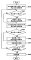
Figure 13 is the flow chart that the overview that the tilt displacement value of putting is detected is shown.
At step S110, create test pattern.Create test pattern by regularly on print media, printing a plurality of test speckles in different discharges.At step S120, use optical pickocff to measure the optical characteristics of each test speckle, and detect information about tilt displacement.In an embodiment, measure the anacamptics concentration of test speckle as optical characteristics.At step S130, determine control information according to detected information, and this control information is arranged in the correcting value memory 217 about tilt displacement.
Passing through among the establishment of the test pattern among the description of step S110 and the step S120 measured optical characteristics carry out detection about the information of tilt displacement.In this example, detect the point that forms by 3 black outlets 13 displacement, as information about tilt displacement along main scanning direction with corresponding each along in the upstream and downstream side of sub scanning direction in the two ends of black outlet array 141.
Figure 14 is illustrated in the test pattern that forms among the step S110 on print media 12.This test pattern is made of 7 test speckles 401 to 407.Each test speckle of formation as described below.At first, by using, print the image that the point by four continuation columns forms with the interval of four row along 3 black outlets 13 of the upstream side of sub scanning direction.Then, carry print media 12, and by using 3 black outlets in downstream, print the image that the point by four continuation columns forms with the interval of four row.In this case, by in Figure 14 from left to right in the mobile print head from discharging China ink along each 3 the black outlets the upstream and downstream side of sub scanning direction, print.
By filling timing place at the interval of four row in supposition, discharge China ink from 3 black outlets along the downstream of sub scanning direction, form test speckle 404.The driving timing of the black outlet 13 by postponing the downstream is offset 1/2 pixel, 1 pixel and 3/2 pixel with the image that will be formed by the black outlet in downstream to the right from the interval of four row among Figure 14, create and test speckle 405,406 and 407.The driving timing of the black outlet 13 by quickening the downstream is offset 1/2 pixel, 1 pixel and 3/2 pixel with the image that will be formed by the black outlet in downstream left from the interval of four row among Figure 14, create and test speckle 403,402 and 401.
The detection of the inclination of use test pattern (displacement)
Explanation detected the point that forms by each 3 the black outlets 13 in the upstream and downstream side method along the displacement of main scanning direction according to the test pattern of being created.Figure 15 A and 15B illustrate the image 408 of test speckle 404 and the figure that the point when having tilt displacement is arranged.In the image 408 of test speckle 404, according to tilt displacement, a some lap and a nothing point part as black streaking 409 and informal voucher line 410 appear.Exist under the situation of tilt displacement, as shown in figure 16, along the point 411 of the upstream side of sub scanning direction with along the displacement L that exists between the point 412 in the downstream of sub scanning direction along main scanning direction.Test speckle 404 is images of being printed by the black outlet 13 in downstream in timing place of supposing the interval of filling four row after black outlet 13 print images of upstream side.For this reason, as by the some lap among Figure 15 B 413 with do not have shown in the some part 414, occur the point 411 of upstream side and downstream point 412 the some lap and do not have a some part.This causes image 408 to have black streaking 409 and informal voucher line 410, shown in Figure 15 A.By this way, can detect the appearance of tilt displacement from the image 408 of test speckle 404.
With explanation detection along the displacement of main scanning direction when having tilt displacement.In the following description, the test speckle 406 of supposing 7 test speckles is the images 415 without any the even gradation of drop-out colour of black streaking or informal voucher line, shown in Figure 17 A.Figure 17 B illustrates the details of the some layout of image 415.
In test speckle 406, the driving timing of the black outlet by postponing the downstream, with the point 412 in downstream from the interval of four row along pixel of main scanning direction skew, form the point 412 in downstream.If there is no tilt displacement, then black streaking and informal voucher line appear in the interval with four row.Yet, as shown in figure 16, the displacement L along main scanning direction appears between the point 412 in the point 411 of upstream side and downstream.This displacement disappears except when the displacement that occurs when postponing the driving timing of black outlet 13 in downstream.Therefore, test speckle 406 has the image 415 of even gradation of drop-out colour.By this way, can detect because clockwise tilt displacement appears in the some displacement along a pixel of main scanning direction between the point 412 in the point 411 of upstream side and downstream.
By from the test speckle of creating by the driving timing of the black outlet that changes the downstream, selecting the image of even gradation of drop-out colour, can detect the some displacement along main scanning direction of conduct about the information of tilt displacement.
At step S120, use optical pickocff to measure the anacamptics concentration of 7 test speckles.By the test speckle that selection from measurement result has high anacamptics concentration, can detect without any test speckle black streaking or informal voucher line, that point is evenly arranged.
The i.e. tilt displacement bearing calibration of the point that forms when the clockwise tilt displacement of appearance and by the upstream and downstream type element when main scanning direction departs from a pixel each other will be described when detecting test speckle 406 as even image.
Inclination (displacement) is proofreaied and correct
Figure 18 is illustrated in the corrected value information (inclination information) that keeps in the correcting value memory 217 of storage inclination information.Correcting value memory 217 keeps about postpone how much to print the information (slant correction amount) of timing signal to proofread and correct in 16 division driving.At group 0, will the value of setting be set to 0 with correct tilt not.At group 1, the value of setting is set to 2 so that two of slant corrections are printed timing signal.At group 2, the value of setting is set to 4 so that four of slant corrections are printed timing signal.At group 3, the value of setting is set to 6 so that six of slant corrections are printed timing signal.At group 4,5,6 and 7, the value of setting is set to 8,10,12 and 14.
In an embodiment, at the group 0 as benchmark, corrected value is set to 0, but the benchmark group is arbitrarily.For example, will organize 7 and be defined as benchmark, and, the value of setting will be set to 2,4,6,8,10,12 and 14 respectively at group 6,5,4,3,2,1 and 0.Opposite with use group 0 as the correction of benchmark, can also accelerate to print timing signal accordingly with the value of setting.
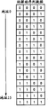
A among Fig. 1 represents to distribute to nozzle numbering NZL, selection piece SBK and the print data DATA of group 0 (G0) to the type element of 7 (G7).B among Fig. 1 represent with Fig. 1 in the layout of the point on print media, printed accordingly of A.Print data is for just being sent to the data of printhead.Proofread and correct for the ease of understanding, the A supposition nozzle array among Fig. 1 does not tilt.The point that " zero " expression is printed based on print data.Print data among Fig. 1 is based on being stored in the print data that transmits in the buffer 213, and tilts the selective printing data and be sent to printhead according to this.Point is arranged and is schematically shown when not having tilt displacement and carrying out the point that forms when printing based on being stored in the print data that transmits in the buffer 213 on print media.
In Fig. 1, from each group, discharge order type element early and begin, be offset print position accordingly in turn with quantity by the control information appointment.To this be described with reference to the B of figure 1.For example, the value of the control information of group 0 is 0.In arranging, institute is arranged in a little in first row, and point is arranged in first to the 3rd row with the corresponding point of the nozzle that belongs to group 0.The value of the control information of group 1 is 2.In arranging with the corresponding point of the nozzle that belongs to group 1, it is blank numbering the corresponding position of 17 (selecting piece 1) with nozzle numbering 16 (selecting piece 0) and nozzle.Begin layout points from numbering 18 corresponding positions with nozzle.In the 4th row, numbering 16 and 17 corresponding position layout points with nozzle.The value of the control information of group 2 is 4.In arranging with the corresponding point of the nozzle that belongs to group 2, it is blank numbering 32 to 35 corresponding positions with nozzle.Begin layout points from numbering 36 corresponding positions with nozzle.In the 4th row, numbering 32 to 35 corresponding position layout points with nozzle.By this way, come deferred printing regularly based on control information.
Figure 27 illustrates to be used for reading the figure of the timing of print data from transmitting buffer 213.In Figure 27, the time passes through from left to right.
N is the count value of block counter 216A, and upgrades in 0 to 15 scope.The N value is 0 in reading for the first time, and the N value is 1 in reading for the second time.S is the count value of stored count device 216B, and the accumulative total (sum) of expression read operation.The S value is set to 0 when print scanned beginning.
When being shown in triggering signal, transmits the number table that illustrates at group 0 each triggering signal (latch signal) in 7 block number of (reading).For example, when first triggering signal of output in Figure 27 when (S=0, N=0), be numbered 0 with group 0 is corresponding.This numbering " 0 " is corresponding to " 0 " in the row of the selection piece of the group among the A that belongs to Fig. 10, and corresponding to " zero " in the row of first among the B of Fig. 1.
The print data that the region representation that adds light grey shading is printed in first row does not add the print data that the region representation of shading is printed in secondary series, and adds the print data that the region representation of Dark grey shading is printed in the 3rd row.Corrected value for 0 every group of group is 0, is 2 for group 1 this corrected value, is 4 for group 2 these corrected values, for group 3 these corrected values is 6, is 8 for group 4 these corrected values, is 10 for group 5 these corrected values, for the group 6 these corrected values is 12, and for the group 7 these corrected values be 14.Along with group # increases, corrected value increases.Figure 27 illustrates for big more group #, further postpones to read beginning regularly.
The parts that explanation are used to generate the print data after the correction.
For example, be 0 o'clock in stored count, the print data of from the piece 0 in the piece 0 in storehouse 0 and storehouse 2, reading piece 0.That is to say, read and be stored in the print data located address 0 (Ad00h) and be stored in the print data that address 20 (Ad20h) is located.In stored count is 1 o'clock, reads print data from the piece 1 in the piece 1 in storehouse 0 and storehouse 2.Read the print data of piece 2 to 15 in turn.
In stored count is 16 o'clock, reads print data from the piece 0 in the piece 0 in storehouse 0 and storehouse 1.In stored count is 17 o'clock, reads print data from the piece 1 in the piece 1 in storehouse 0 and storehouse 1.Read the print data of piece 2 to 15 in turn.
In stored count is 22 o'clock, reads print data from the piece 6 in the piece 6 in storehouse 0 and storehouse 1.Read the print data at address 16 and 6 places, as the print data of piece 6.
Figure 28 is to be the schematic diagram of the generation of 22 o'clock transmission data in stored count.Transmit data b 0 and be the print data that is used to organize 0 type element.Because transmission block is piece 6, therefore transmit data b 0 and be the print data that is used to organize 0 piece 6, promptly be used for the print data of the section 6 of printhead 11.And, transmit data b 7 and be the print data that is used to organize 7 piece 6, promptly be used for the print data of the section 118 of printhead 11.
Figure 25 is the flow chart of the selection of the print data of being undertaken by data selection circuit 215.Will be with reference to this flow chart, illustrate value at block counter 216A be 6 and the value of stored count device be to generate the method that transmits data at 22 o'clock.Data selection circuit 215 comprises the comparator that a value that is used for corrected value and block counter 216A compares.
After timing signal was printed in input, print data was read in the address 16 as the storehouse 1 in first storehouse from transmit buffer 213, and latchs this print data (step S310) by the first latching sections (not shown) temporarily.Subsequently, print data is read in the address 6 as the storehouse 0 in second storehouse from transmit buffer 213, and latchs this print data (step S320) by the second latching sections (not shown) temporarily.
The corrected value of group 0 and the count value of block counter 216A are compared (step S330).As organizing the result that 0 corrected value " 0 " count value " 6 " with block counter 216A compares, satisfy the condition of corrected value≤count value.Therefore, select the print data b0 at 16 places, address, and latch (step S340) by the 3rd latching sections (not shown).Then, counter (step S360) is latched in renewal.Judge whether to have latched the print data (step S370) of all groups.In this case, organize 0 print data owing to latched, so step S330 is returned in this processing.
To organize 1 carry out with to organizing the identical processing of processing of 0 execution.Since group 1 corrected value be 2 and count value be 6, therefore satisfy the condition of corrected value≤count value.Therefore, select the print data b1 at 16 places, address, and latch (step S340) by the 3rd latching sections (not shown).When the 3rd latching sections in step S340 or S350 latchs print data b0 to b7, upgrade and latch counter (step S360).
To repeating identical processing up to group 7.When finishing group 0, will be sent to printhead 11 by the 3rd latching sections latched data at step S380 to the processing of organizing 7.
As for group 4, corrected value be 8 and the count value of block counter 216A be 6, so do not satisfy the condition of corrected value≤count value.Carry out the judgement among the step S330, and this processing enters step S350, the print data b4 at 6 places, address is latched (step S350) by the 3rd latching sections.Owing to group 7, do not satisfy the condition of corrected value≤count value for group 5, therefore latch by print data b5, b6 and the b7 of the 3rd latching sections to 6 places, address.As a result of, generate transmission data b 0 to b7.
To sum up above-mentioned processing.As shown in figure 28, the data that keep according to 16 places in the address form transmission data b 0 to b3, and form transmission data b 4 to b7 according to the data that 6 places in the address keep.
Notice that the counter that latchs that the quantity of the print data b0 to b7 that latched by the 3rd latching sections is counted is being counted after 8 times accordingly with group 0 to 7, and it is 0 that this counting is emptied.
As mentioned above, based on the value of block counter 216A, the value of control information and the data of reading, generate the data that will be sent to print data transfer circuit 219 from the transmission buffer.
As shown in figure 28, group 0 to 3 transmission data b 0 to b3 is to be the print data of the secondary series that should print originally in 22 o'clock in stored count.The transmission data b 4 to b7 of group 4 to 7 is first print datas that are listed as that should print in last timing place.By print data transfer circuit 219 the transmission data that generated are transferred to printhead 11 together with the HCLK signal that is transmitted 218 generations of CLK maker by data.
Figure 29 is to be the schematic diagram of the generation of 34 o'clock transmission data in stored count.
Read the print data of piece 2 to transmit this print data from the address 22 and 12 of transmitting buffer 213.The corrected value of group 0 to 7 and the count value " 2 " of block counter 216A are compared.As a result, select the print data at 21 places, address as the group 0 of the condition that satisfies corrected value≤count value and 1 print data b0 and b1.The print data of selecting 11 places, address is as the print data that does not satisfy the group 2 to 7 of this condition.
Print data according to Figure 25 is selected flow chart, reads print data from two storehouses of transmitting buffer 213, and is latched by first and second latching sections.By selecting these print datas, generate and transmit data, and latch by the 3rd latching sections.As alternate manner, can also only use a latching sections to control.Figure 26 illustrates the flow chart that only uses the situation that a latching sections controls.
After timing signal is printed in input, from transmit buffer 213, be used as in the address 16 in storehouse 1 in first storehouse and read print data (step S410).The corrected value of group 0 and the count value of block counter 216A are compared (step S420).As organizing the result that 0 corrected value " 0 " count value " 6 " with block counter 216A compares, satisfy the condition of corrected value≤count value.Therefore, by the data b 0 (step S430) at latching sections latch address 16 places.
Then, from transmit buffer 213, be used as in the address 16 in storehouse 0 in second storehouse and read print data (step S440).In step S450 and S460, the print data of the group that do not satisfy the condition among the step S420 is latched.That is to say, only latch the print data of the group of the condition that satisfies corrected value>count value.
At step S470, upgrade and to latch counter, and to organize 0 to 7 in turn execution in step S420 to S470 (step S480).As a result, generate transmission data b 0 to b7.At step S490, the transmission data that generated are sent to printhead 11, and this processing finishes.
In stored count is 22 o'clock, the print data b0 to b3 at latch address 13 places only in step S430, and in step S460 the print data b4 to b7 at latch address 3 places.
In an embodiment, read the print data in two storehouses from transmitting buffer 213.For first row, read the print data in storehouse 0 and as the print data in the storehouse 2 of the print data of previous column.Yet first row are begin columns, and storehouse 2 does not keep the print data of previous column.Therefore, just 2 read print data from the storehouse all for naught, and in the printing of first row, do not use this print data.Similarly, for the 4th row, read the print data in storehouse 0 and as the print data in the storehouse 2 of the print data of previous column.Yet the 4th row are rank rears, and storehouse 0 does not keep the print data that will print in the 4th row.Therefore, just 0 read print data from the storehouse all for naught, and in the printing of the 4th row, do not use this print data.
As described in an embodiment, the present invention can adopt following structure: always read the print data in two storehouses, and for first row and rank rear, just read the print data in a storehouse all for naught.Can also realize identical effect by following structure: only read the print data in a storehouse for first row and rank rear, make the print data of only reading storehouse 0 for first row, and only read the print data in storehouse 2 for the 4th row.
Fig. 2 illustrates the layout of proofreading and correct the next point that forms by the tilt displacement of embodiment on print media.Blank spot in the tilt displacement timing formation Fig. 2 that does not carry out embodiment.
When tilt displacement occurring, point should be arranged in the position formation that column region wherein departs from originally from them.The quantity of this point is different between group.In an embodiment in Shuo Ming the tilt displacement, the quantity of the point that forms at the deviation position place is from increasing to 2 of group 1 as 0 of the group 0 of benchmark, group 24 and organize 36.
For should be arranged in the point that position that column region wherein departs from forms originally from it, the tilt displacement of embodiment is proofreaied and correct and is changed the print data of distributing to type element.More specifically, when the print data of type element is distributed in generation, can be from two print datas, i.e. selective printing data in the print data of the print data in prostatitis and previous column.
As mentioned above, when group comprises that being arranged in them should be arranged in the point in wherein the column region originally and be arranged in the point of the position of departing from from this zone, along main scanning direction only arranged offset at the point of the position of departing from from this zone.By this way, can proofread and correct so that it falls into identical column region point.
Therefore, the reduction that can suppress picture quality is proofreaied and correct in the tilt displacement of embodiment.
Second embodiment
Tilt displacement during distributing drives is proofreaied and correct
According to inkjet printing methods, use heater or piezoelectric element energy to be applied to China ink, and discharge ink droplet with print image as type element.This inkjet printing methods suffers so-called crosstalking (crosstalk) phenomenon, wherein when when black outlet is discharged ink droplet, to the contiguous black outlet ripple etc. of exerting pressure, makes from the discharge instability of contiguous black outlet.Therefore, expectation drives with the distributing that the drive sequences of discharging ink droplet from contiguous black outlet discontinuously prints element.Even for carrying out the structure that distributing drives, also can using inclined displacement correction.Similar with first embodiment, this tilt displacement correction will be described.
Note, with the explanation of omitting the content identical with the content of first embodiment.
Figure 19 and 20 is the figure that are used to illustrate the tilt displacement correction when printing with the drive sequences of discharging the type element of ink droplet from two black outlets of vicinity discontinuously.In a second embodiment, the drive sequences with piece 0 → 11 → 6 → 1 → 12 → 7 → 2 → 13 → 8 → 3 → 14 → 9 → 4 → 15 → 10 → 5 drives type element.
Similar with Fig. 1, Figure 19 illustrates the nozzle numbering NZL of the type element of distributing to each group, the figure that selects piece SBK, print data DATA and point to arrange.Figure 20 illustrates the layout that ought carry out the point that the tilt displacement timing forms as shown in figure 19 on print media.
Figure 30 illustrates from transmitting buffer 213 to read the figure of the timing of print data.
The print data that the region representation that adds light grey shading is printed in first row does not add the print data that the region representation of shading is printed in secondary series, and adds the print data that the region representation of Dark grey shading is printed in the 3rd row.Corrected value for 0 every group of group is 0, is 1 for group 1 this corrected value, is 2 for group 2 these corrected values, for group 3 these corrected values is 3, is 4 for group 4 these corrected values, is 5 for group 5 these corrected values, for the group 6 these corrected values is 6, and for the group 7 these corrected values be 7.
The parts that explanation are used to generate the print data after the correction.
In stored count is 0 to 15 o'clock, and data selection circuit 215 is read the print data of storehouse 0 and 2 from transmitting buffer 213.In stored count is 16 to 31 o'clock, and data selection circuit 215 is read the print data of storehouse 1 and 0.In stored count is 32 to 47 o'clock, and data selection circuit 215 is read the print data of storehouse 2 and 1.In stored count is 48 to 63 o'clock, and data selection circuit 215 is read the print data of storehouse 1 and 0.For example, be 0 o'clock in stored count, data selection circuit 215 is read the print data of the print data at address 0 and 20 places as piece 0.In stored count is 22 o'clock, and data selection circuit 215 is read the print data of the print data at address 12 and 2 places as piece 2.
Figure 31 is to be the schematic diagram of the generation of 18 o'clock transmission data in stored count.
As shown in Figure 31, being used to organize 0 to 2 transmission data b 0 to b2 and being in stored count is the print data of the secondary series that originally should print in 18 o'clock.Be used to organize 3 to 7 transmission data b 4 to b7 and be the print data of first row that timing place before 16 timings should print originally.By print data transfer circuit 219 the transmission data that generated are transferred to printhead 11 together with the HCLK signal that is transmitted 218 generations of CLK maker by data.
Figure 32 is to be the schematic diagram of the generation of 37 o'clock transmission data in stored count.
Read the print data of print data from the address 27 and 17 of transmitting buffer 213 with transmission block 7.The corrected value of group 0 to 7 and the count value " 5 " of block counter 216A are compared.As a result, select the print data b0 to b5 of the print data at 27 places, address as the group 0 to 5 of the condition that satisfies corrected value≤delivery value.The print data of selecting 17 places, address is as the print data that does not satisfy the group 6 to 7 of this condition.
When carrying out the distributing driving, as second embodiment, the drive sequences among the drive sequences and first embodiment is different.Yet, second embodiment and first embodiment do not have aspect following different: before data transmit counting and quantity unanimity by the control information appointment, second embodiment latchs the print data of previous column, as being used for every group of print data of discharging order type element early.
Second embodiment can carry out that tilt displacement is proofreaied and correct and irrelevant with the drive sequences of type element.
Other embodiment
The processing that will be sent to the data of printhead has been described, but these processing are not limited to foregoing.
For example, the form that is stored in the data in the print buffer 204 is not limited to raster format, and can be column format.In this case, as long as this data format is column format, and corresponding to above-mentioned of printhead, the data that then will be stored in the print buffer 204 are stored in the print buffer 213, and need not to use H-V converter 205 and nozzle buffer 211.
In the above-described embodiments, transmit buffer and have and three corresponding zones of row, and generate the transmission data according to the view data of two row in these row.Yet, the invention is not restricted to this structure.
For example, according to the quantity of the quantity of the quantity of the type element of gradient, arrays of printing elements, piece and every type element etc., transmit that buffer can have and four corresponding zones of row.In this case, the view data of three row from these row generates the transmission data.
Can also also this inclination information be stored in the correcting value memory 217 from the main frame 200 input inclination information that are connected to PRN device.
Embodiments of the invention provide a kind of Method of printing that is used for PRN device, described PRN device comprises along first direction array that extend, that be used for China ink is discharged to the type element on the print media, it is that unit drives type element that described PRN device is used for the piece, each piece comprises that described method comprises along the group of the type element of first direction layout: detect and make the error of described first direction from the layout of the array of the PRN device inside type element that predetermined direction departs from; And depart from the printing that comes the type element in the piece that depends on the piece under each type element and regularly adjust based on detected, wherein, determine adjustment that piece is carried out with respect to reference block, proportional from the distance of reference block with this piece basically to the adjustment that each piece carries out along first direction.
Embodiments of the invention provide a kind of and have comprised along first direction PRN device that extend, that be used for China ink is discharged to the array of the type element on the print media, it is that unit drives described type element that described PRN device is used for the piece, each piece comprises along the group of the type element of first direction layout, described PRN device comprises: detector is used for detecting the error of the layout of the array that makes the inner type element of PRN device that first direction departs from from predetermined direction; And compensating unit, be used for based on detected skew, printing to the type element in the piece that depends on the piece under each type element is regularly adjusted, wherein, determine adjustment that piece is carried out with respect to reference block, proportional from the distance of reference block with this piece basically to the adjustment that each piece carries out along first direction.
Although the present invention has been described with reference to exemplary embodiments, should be appreciated that, the invention is not restricted to disclosed exemplary embodiments.The scope of appended claims meets the wideest explanation, to comprise all this class modification and equivalent structure and functions.
Claims (7)
1. a PRN device (100), the printhead of described PRN device (11) has the arrays of printing elements (141 that is arranged with a plurality of type elements (13), 142,143,144), wherein from type element along the upstream side of the orientation of described a plurality of type elements, described a plurality of type element is divided into a plurality of groups (G0-G7), the quantity of the type element in each group is identical, and type element from described upstream side, each type element in each group is distributed to each piece in turn, described quantity is identical with the quantity of type element in each group, and when scanning based on view data by the direction of intersecting with described orientation on described printhead (11) edge, time-division drives each piece, print, described PRN device is characterised in that and comprises:
Obtain parts, be used to obtain the inclination information of described arrays of printing elements along the scanning direction of described printhead;
Print buffer (204) is used to store and is used for the view data that the single pass by described printhead prints;
Transmit buffer (213), be used at each row the view data of storing a plurality of row that used by described arrays of printing elements in the following view data: this image data storage and is used for printing by a plurality of type elements in described print buffer;
Read control assembly (201,206), be used for, from described transmission buffer, read the view data at least two continuation columns, that will in different lines, print by same block of arrays of printing elements described in the view data of a plurality of row at each piece;
Alternative pack (215), be used for based on described inclination information, at each group, from by the view data of selecting row at least the described view data that reads two continuation columns that control assembly reads at each type element of same block, and selected view data rearranged to being sent to the view data of described printhead;
Write control assembly (201,206), be used for newly reading the view data of row of described arrays of printing elements from described print buffer, and in described transmission buffer as lower area in rewrite: this zone finished by as described in read reading that control assembly carries out, and should the zone corresponding with row of described arrays of printing elements; And
Transfer member (219), the view data that is used for being rearranged by described alternative pack is sent to described printhead.
2. PRN device according to claim 1 is characterized in that, also comprises nozzle buffer (211), and described nozzle buffer stores is by carrying out the view data that the H-V conversion is obtained to being stored in view data in the described print buffer,
Wherein, the described control assembly of writing rewrites by reading the view data that is stored in the described nozzle buffer.
3. PRN device according to claim 1 and 2 is characterized in that,
Described alternative pack has and is used for two latching sections that the view data to two continuation columns of arrays of printing elements described in the view data of three row latchs respectively, and
Arbitrary view data in the view data that described alternative pack is selected to be latched by described two latching sections.
4. PRN device according to claim 1 and 2 is characterized in that,
Described alternative pack has and is used for the latching sections that the view data to two continuation columns of arrays of printing elements described in the view data of three row latchs in turn, and
When view data that described alternative pack is not selected to latch earlier, the view data that described alternative pack latchs after selecting.
5. PRN device according to claim 1 is characterized in that, described acquisition parts comprise optical pickocff, and obtains described inclination information from the image that the type element at the two ends by described arrays of printing elements forms.
6. PRN device according to claim 1 is characterized in that described printhead comprises ink jet-print head.
One kind control PRN device (100) method, the printhead of described PRN device (11) has the arrays of printing elements (141 that is arranged with a plurality of type elements (13), 142,143,144), wherein from type element along the upstream side of the orientation of described a plurality of type elements, described a plurality of type element is divided into a plurality of groups (G0-G7), the quantity of the type element in each group is identical, and type element from described upstream side, each type element in each group is distributed to each piece in turn, described quantity is identical with the quantity of type element in each group, and when scanning based on view data by the direction of intersecting with described orientation on described printhead (11) edge, time-division drives each piece, print, described method is characterised in that and comprises:
Obtain step, be used to obtain the inclination information of described arrays of printing elements along the scanning direction of described printhead;
Be used for to be used for image data storage that the single pass by described printhead prints step in print buffer (204);
Be used for to be stored in the view data of a plurality of row that use by described arrays of printing elements in the view data of described print buffer, be stored in the step that transmits in the buffer (213) at each row;
Read the control step, be used for, from described transmission buffer, read the view data at least two continuation columns, that will in different lines, print by same block of arrays of printing elements described in the view data of a plurality of row at each piece;
Select step, be used for based on described inclination information, at each group, from in the described view data that reads two continuation columns reading at each type element of same block the control step, selecting the view data of row at least, and selected view data is rearranged to being sent to the view data of described printhead;
Write the control step, be used for newly reading the view data of row of described arrays of printing elements from described print buffer, and in described transmission buffer as lower area in rewrite: reading control reading in the step as described in has finished in this zone, and should the zone corresponding with row of described arrays of printing elements;
Transfer step, the view data that is used for rearranging in described selection step is sent to described printhead; And
Printing step is used for printing based on the view data that transmits in described transfer step.
Applications Claiming Priority (3)
| Application Number | Priority Date | Filing Date | Title |
|---|---|---|---|
| JP2007173113 | 2007-06-29 | ||
| JP2007173113 | 2007-06-29 | ||
| JP2007-173113 | 2007-06-29 |
Publications (2)
| Publication Number | Publication Date |
|---|---|
| CN101332703A CN101332703A (en) | 2008-12-31 |
| CN101332703B true CN101332703B (en) | 2011-08-10 |
Family
ID=39720705
Family Applications (1)
| Application Number | Title | Priority Date | Filing Date |
|---|---|---|---|
| CN2008101291206A Active CN101332703B (en) | 2007-06-29 | 2008-06-30 | Printing apparatus and control method therefor |
Country Status (4)
| Country | Link |
|---|---|
| US (1) | US8223382B2 (en) |
| EP (1) | EP2008823B1 (en) |
| JP (2) | JP5571884B2 (en) |
| CN (1) | CN101332703B (en) |
Families Citing this family (9)
| Publication number | Priority date | Publication date | Assignee | Title |
|---|---|---|---|---|
| US8223382B2 (en) * | 2007-06-29 | 2012-07-17 | Canon Kabushiki Kaisha | Printing apparatus and control method therefor |
| JP2011088391A (en) * | 2009-10-23 | 2011-05-06 | Canon Inc | Recorder, and control method thereof |
| JP5501127B2 (en) * | 2010-07-06 | 2014-05-21 | キヤノン株式会社 | Recording apparatus and recording control method |
| JP6080475B2 (en) * | 2011-11-29 | 2017-02-15 | キヤノン株式会社 | Inkjet recording apparatus and inkjet recording method |
| TW201416871A (en) * | 2012-10-17 | 2014-05-01 | Wistron Corp | Data transmission apparatus and method |
| JP6869033B2 (en) * | 2017-01-12 | 2021-05-12 | キヤノン株式会社 | Inkjet recording device and control method |
| WO2018199884A1 (en) * | 2017-04-24 | 2018-11-01 | Hewlett-Packard Development Company, L.P. | Determining print orders |
| EP3784495B1 (en) * | 2018-04-23 | 2024-03-27 | Canon Production Printing Holding B.V. | Method of fast nozzle failure detection |
| JP7428196B2 (en) | 2022-02-18 | 2024-02-06 | カシオ計算機株式会社 | Print data correction method, program and printing device |
Family Cites Families (7)
| Publication number | Priority date | Publication date | Assignee | Title |
|---|---|---|---|---|
| JP2001205789A (en) * | 2000-01-24 | 2001-07-31 | Canon Inc | Ink jet recorder and ink jet recording method |
| JP4666816B2 (en) * | 2001-06-07 | 2011-04-06 | キヤノン株式会社 | Recording apparatus, control method therefor, and program |
| JP4208488B2 (en) | 2002-06-06 | 2009-01-14 | キヤノン株式会社 | Inkjet recording device |
| JP5058523B2 (en) * | 2005-06-28 | 2012-10-24 | キヤノン株式会社 | Recording method and recording apparatus |
| US7850268B2 (en) | 2005-06-28 | 2010-12-14 | Canon Kabushiki Kaisha | Recording method and recording apparatus |
| JP2007038649A (en) | 2005-07-08 | 2007-02-15 | Canon Inc | Ink jet recording apparatus and ink jet recording method |
| US8223382B2 (en) * | 2007-06-29 | 2012-07-17 | Canon Kabushiki Kaisha | Printing apparatus and control method therefor |
-
2008
- 2008-06-09 US US12/135,560 patent/US8223382B2/en active Active
- 2008-06-25 JP JP2008166544A patent/JP5571884B2/en not_active Expired - Fee Related
- 2008-06-27 EP EP08159219.8A patent/EP2008823B1/en active Active
- 2008-06-30 CN CN2008101291206A patent/CN101332703B/en active Active
-
2014
- 2014-05-01 JP JP2014094871A patent/JP5788059B2/en active Active
Also Published As
| Publication number | Publication date |
|---|---|
| JP5788059B2 (en) | 2015-09-30 |
| JP5571884B2 (en) | 2014-08-13 |
| US8223382B2 (en) | 2012-07-17 |
| EP2008823B1 (en) | 2015-08-12 |
| CN101332703A (en) | 2008-12-31 |
| JP2014159171A (en) | 2014-09-04 |
| EP2008823A3 (en) | 2009-08-05 |
| JP2009029123A (en) | 2009-02-12 |
| EP2008823A2 (en) | 2008-12-31 |
| US20090002728A1 (en) | 2009-01-01 |
Similar Documents
| Publication | Publication Date | Title |
|---|---|---|
| CN101332703B (en) | Printing apparatus and control method therefor | |
| US6283572B1 (en) | Dynamic multi-pass print mode corrections to compensate for malfunctioning inkjet nozzles | |
| CN100469576C (en) | Printing apparatus and control method therefor | |
| CN102582255B (en) | Printing apparatus and adjustment pattern printing method | |
| CN101157296B (en) | Liquid droplet ejection device, liquid droplet ejection device control method as well as storage medium | |
| WO2000064677A1 (en) | Image forming device | |
| CN101332701B (en) | Recording apparatus | |
| CN1874894B (en) | Printing method, printing device, printing system | |
| US6733101B2 (en) | Printing apparatus and control method therefor | |
| CN101905570A (en) | Recording equipment and method for adjusting recording position | |
| US9073312B2 (en) | Printing with multiple printhead dies | |
| JP5489424B2 (en) | Recording apparatus and adjustment value acquisition method for adjusting the recording position of the recording apparatus | |
| CN100408335C (en) | Liquid jetting device and liquid jetting method | |
| CN103042827B (en) | Printing apparatus and processing method thereof | |
| CN102173199A (en) | Printer, printing method, program and printing system | |
| US7070253B2 (en) | Ink-jet printing method and apparatus | |
| JP4508549B2 (en) | Image recording apparatus and control method thereof | |
| JP5748803B2 (en) | Recording apparatus and recording position adjusting method | |
| US7946678B2 (en) | Printing apparatus and data processing method | |
| US20050146548A1 (en) | Method and apparatus of operating a printer | |
| JP5274377B2 (en) | Recording apparatus and control method | |
| JP2009039958A (en) | Recording apparatus | |
| JP2003225999A (en) | Image recording apparatus and control method therefor | |
| US20060071995A1 (en) | Ink-jet recording apparatus preventing recording surface of recording medium and paper discharge roller from contamination | |
| JPH08132601A (en) | Recorder |
Legal Events
| Date | Code | Title | Description |
|---|---|---|---|
| C06 | Publication | ||
| PB01 | Publication | ||
| C10 | Entry into substantive examination | ||
| SE01 | Entry into force of request for substantive examination | ||
| C14 | Grant of patent or utility model | ||
| GR01 | Patent grant |