CN101331587B - Apparatus and method for depositting material pattern on substrate - Google Patents
Apparatus and method for depositting material pattern on substrate Download PDFInfo
- Publication number
- CN101331587B CN101331587B CN2006800468477A CN200680046847A CN101331587B CN 101331587 B CN101331587 B CN 101331587B CN 2006800468477 A CN2006800468477 A CN 2006800468477A CN 200680046847 A CN200680046847 A CN 200680046847A CN 101331587 B CN101331587 B CN 101331587B
- Authority
- CN
- China
- Prior art keywords
- mask
- substrate
- anchor clamps
- constructed
- selected anchor
- Prior art date
- Legal status (The legal status is an assumption and is not a legal conclusion. Google has not performed a legal analysis and makes no representation as to the accuracy of the status listed.)
- Expired - Fee Related
Links
Images


Classifications
-
- C—CHEMISTRY; METALLURGY
- C23—COATING METALLIC MATERIAL; COATING MATERIAL WITH METALLIC MATERIAL; CHEMICAL SURFACE TREATMENT; DIFFUSION TREATMENT OF METALLIC MATERIAL; COATING BY VACUUM EVAPORATION, BY SPUTTERING, BY ION IMPLANTATION OR BY CHEMICAL VAPOUR DEPOSITION, IN GENERAL; INHIBITING CORROSION OF METALLIC MATERIAL OR INCRUSTATION IN GENERAL
- C23C—COATING METALLIC MATERIAL; COATING MATERIAL WITH METALLIC MATERIAL; SURFACE TREATMENT OF METALLIC MATERIAL BY DIFFUSION INTO THE SURFACE, BY CHEMICAL CONVERSION OR SUBSTITUTION; COATING BY VACUUM EVAPORATION, BY SPUTTERING, BY ION IMPLANTATION OR BY CHEMICAL VAPOUR DEPOSITION, IN GENERAL
- C23C14/00—Coating by vacuum evaporation, by sputtering or by ion implantation of the coating forming material
- C23C14/04—Coating on selected surface areas, e.g. using masks
- C23C14/042—Coating on selected surface areas, e.g. using masks using masks
-
- C—CHEMISTRY; METALLURGY
- C23—COATING METALLIC MATERIAL; COATING MATERIAL WITH METALLIC MATERIAL; CHEMICAL SURFACE TREATMENT; DIFFUSION TREATMENT OF METALLIC MATERIAL; COATING BY VACUUM EVAPORATION, BY SPUTTERING, BY ION IMPLANTATION OR BY CHEMICAL VAPOUR DEPOSITION, IN GENERAL; INHIBITING CORROSION OF METALLIC MATERIAL OR INCRUSTATION IN GENERAL
- C23C—COATING METALLIC MATERIAL; COATING MATERIAL WITH METALLIC MATERIAL; SURFACE TREATMENT OF METALLIC MATERIAL BY DIFFUSION INTO THE SURFACE, BY CHEMICAL CONVERSION OR SUBSTITUTION; COATING BY VACUUM EVAPORATION, BY SPUTTERING, BY ION IMPLANTATION OR BY CHEMICAL VAPOUR DEPOSITION, IN GENERAL
- C23C14/00—Coating by vacuum evaporation, by sputtering or by ion implantation of the coating forming material
- C23C14/22—Coating by vacuum evaporation, by sputtering or by ion implantation of the coating forming material characterised by the process of coating
- C23C14/54—Controlling or regulating the coating process
-
- C—CHEMISTRY; METALLURGY
- C23—COATING METALLIC MATERIAL; COATING MATERIAL WITH METALLIC MATERIAL; CHEMICAL SURFACE TREATMENT; DIFFUSION TREATMENT OF METALLIC MATERIAL; COATING BY VACUUM EVAPORATION, BY SPUTTERING, BY ION IMPLANTATION OR BY CHEMICAL VAPOUR DEPOSITION, IN GENERAL; INHIBITING CORROSION OF METALLIC MATERIAL OR INCRUSTATION IN GENERAL
- C23C—COATING METALLIC MATERIAL; COATING MATERIAL WITH METALLIC MATERIAL; SURFACE TREATMENT OF METALLIC MATERIAL BY DIFFUSION INTO THE SURFACE, BY CHEMICAL CONVERSION OR SUBSTITUTION; COATING BY VACUUM EVAPORATION, BY SPUTTERING, BY ION IMPLANTATION OR BY CHEMICAL VAPOUR DEPOSITION, IN GENERAL
- C23C14/00—Coating by vacuum evaporation, by sputtering or by ion implantation of the coating forming material
- C23C14/22—Coating by vacuum evaporation, by sputtering or by ion implantation of the coating forming material characterised by the process of coating
- C23C14/56—Apparatus specially adapted for continuous coating; Arrangements for maintaining the vacuum, e.g. vacuum locks
- C23C14/562—Apparatus specially adapted for continuous coating; Arrangements for maintaining the vacuum, e.g. vacuum locks for coating elongated substrates
Abstract
An apparatus for depositing a pattern of material on a substrate includes reciprocating aperture mask. A feed magazine houses a plurality of jigs, each of the jigs configured to support a mask having apertures defining a pattern. A shuttle mechanism receives a selected jig presented by the feed magazine and establishes contact between the mask of the selected jig and the substrate. The shuttle mechanism moves the selected jig in line with the substrate and relative to the deposition source so that deposition material passes through the apertures of the mask of the selected jig to develop the pattern of the deposition material on the substrate.
Description
Technical field
The present invention relates to use the pattern of aperture mask deposition materials in substrate.
Background technology
Can in substrate, form the pattern of material by using aperture mask or template.Aperture mask is arranged between substrate and the sedimentary origin.Be directed to substrate and pass the eyelet of mask from the material of sedimentary origin, thereby in substrate, form and the corresponding pattern of pattern of apertures.
This type of pattern can be deposited in the substrate for various purposes.As in an example, deposit the formation circuit layer in order by making material pass mask pattern, can in substrate, form circuit.Inter alia, aperture mask can be used for forming diversified circuit, comprises discrete and integrated circuit, LCD, organic light emitting diode display.The formation of small geometry circuit elements relates to accurate alignment and the positioning control to substrate and aperture mask.The present invention has satisfied these needs and other needs, and has other advantage above prior art.
Summary of the invention
Embodiments of the invention relate to the reciprocating type aperture mask of use material are deposited on suprabasil system and method.An embodiment relates to the device that is used for deposition materials pattern in substrate.This device comprises transfer roller structure that transmits substrate and the admittance roll structure of admitting substrate on it.Sedimentary origin is oriented to the deposition materials directed toward substrate.Feeding warehouse holds a plurality of anchor clamps, and each anchor clamps is constructed to have the supporting mask of the eyelet of limiting pattern.Shuttle structure is admitted the selected anchor clamps of being sent by feeding warehouse, and contacting between the mask of setting up selected anchor clamps and the substrate.Shuttle structure moves selected anchor clamps and substrate in line and with respect to sedimentary origin, so that deposition materials passes the eyelet of the mask of selected anchor clamps, to form the deposition materials pattern in substrate.
This device also can comprise one or more alignment structures.Alignment structures can be used for substrate with respect to mask alignment mask being alignd with respect to substrate, and/or adjusts the position of mask with respect to selected anchor clamps.
In an example, mask comprises collimation mark, and anchor clamps comprise benchmark.The mask alignment structure is constructed to make the mask collimation mark to align with the anchor clamps benchmark with respect to one or more axis.The mask alignment structure can comprise one or more controllable drivers that are connected to mask.Driver can controllably be adjusted the tension force of the mask on the selected anchor clamps.
In another example, this device comprises substrate alignment structures and mask alignment structure, and described substrate alignment structures is constructed to adjust the position of substrate, and described mask alignment structure is constructed to adjust the position of the mask on the selected anchor clamps.Each alignment structures can controllably be adjusted, and is beneficial to aliging between substrate and the mask.
The substrate alignment structures can comprise suprabasil mark and the lateral attitude of substrate be transferred to the width of cloth material guiding piece in precalculated position.Shuttle structure is constructed to adjust the position of the mask on the selected anchor clamps, so that select anchor clamps and substrate when mobile in line, the one-tenth pattern part and the mask alignment of substrate when shuttle structure makes.According to concrete an enforcement, described substrate alignment structures comprises width of cloth material locating platform structure, and this structure is constructed to when shuttle structure makes selected anchor clamps and substrate mobile in line, and the adjustment substrate is with respect to the position of mask.
In a structure, width of cloth material locating platform structure can comprise support plate and gas transfer structure.This gas transfer structure can be used for providing between basad and the support plate a large amount of gas.In another structure, width of cloth material locating platform structure comprises at least one roller, and described roller is arranged near each corresponding end of support plate.One or two described roller can be constructed to cooling substrate when substrate moves past roller.The gas transfer structure can be basad and support plate between a large amount of air of supply so that the substrate cooling.In addition, oscillator can be connected to support plate and be constructed to make supporting member to produce oscillating movement.
It is the surface on plane that substrate has basic.Shuttle structure is constructed to: with respect to substrate, move selected anchor clamps towards the direction that departs from this base plane, so that the mask on the selected anchor clamps of substrate joint and disengaging.Shuttle structure is constructed to and can moves selected anchor clamps at first offset direction, so that mask engaged substrate before deposition; And move selected anchor clamps at second offset direction, so that finishing the back in deposition, mask breaks away from substrate.Shuttle structure is constructed to move selected anchor clamps in reciprocating mode, so that reuse selected anchor clamps in deposition process.
This device can also comprise discharging structure and unload feed bin that this unloads feed bin and is constructed to hold a plurality of used anchor clamps.Discharging structure moves to used anchor clamps and unloads feed bin from shuttle structure.In some constructions, feeding warehouse also can be used as and unloads feed bin.The feeding structure of this feeding warehouse is constructed to admit the used anchor clamps that transmitted by shuttle structure.
In some concrete enforcements, the pattern of the mask qualification on other anchor clamps in the pattern that mask limited at least some anchor clamps in a plurality of anchor clamps and the described a plurality of anchor clamps is different.Substrate can be continuous width of cloth material.Mask and/or substrate can comprise thin polymer film.
An alternative embodiment of the invention relate to a kind of in substrate the deposition materials method of patterning.Move anchor clamps selected from a plurality of anchor clamps from feeding warehouse, each anchor clamps is constructed to have the supporting mask of the eyelet of limiting pattern.Move substrate with respect to sedimentary origin.Transmit selected anchor clamps, it is engaged with substrate in primary importance (being cooperation position).Make the same moved further of anchor clamps and substrate, make deposition materials pass the eyelet of the mask of selected anchor clamps simultaneously, in substrate, to form the deposition materials pattern.Mask breaks away from respect to substrate, and selected anchor clamps can return primary importance after being synchronized with the movement of selected anchor clamps and mask, so that reuse this anchor clamps.Alternatively, Xuan Ding anchor clamps can be transferred into feeding warehouse or other facility after use.In substrate, form in the process of deposition materials pattern, can cool off the mask on substrate and the selected anchor clamps.In some constructions, the pattern that limits of the mask on other anchor clamps in the pattern that mask limited at least some anchor clamps in a plurality of anchor clamps and the described a plurality of anchor clamps is different.
This method may relate to substrate and align with respect to substrate with respect to mask alignment and/or mask.For example, can adjust the position of the mask of the position of substrate and selected anchor clamps, so that substrate is alignd mutually with mask.Can adjust the position of mask along one or more axis of mask with respect to selected anchor clamps.Mask can be strained automatically with respect to one or more axis of mask.The offset in alignment of deposition cycle can determine, and can be in order to adjust aliging of substrate and mask in follow-up deposition cycle.
Above general introduction of the present invention is not to be intended to illustrate each embodiment disclosed in this invention or every concrete enforcement of the present invention.In conjunction with the drawings, referring to following embodiment and claim, will clearly be familiar with advantage of the present invention and achievement and understand the present invention more all sidedly.
Description of drawings
Figure 1A illustrates according to embodiments of the invention, comprises the reciprocating type aperture mask depositing system of feeding warehouse;
Figure 1B illustrates according to embodiments of the invention, comprises feeding warehouse and the reciprocating type aperture mask depositing system that unloads feed bin;
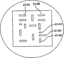
Fig. 2 A and 2B illustrate the aperture mask according to the embodiment of the invention, and this aperture mask has a plurality of patterns that can be used for the eyelet of depositing system of qualification;
Fig. 3 A is the vertical view according to the anchor clamps/mask assembly of the embodiment of the invention;
Fig. 3 B illustrates the viewgraph of cross-section that is used to strain the structure of aperture mask according to the embodiment of the invention;
Fig. 4 A and 4B illustrate part vertical view and the end view that comprises the single-stage depositing system of aligned portions according to the embodiment of the invention respectively;
Fig. 4 C and 4D illustrate respectively according to an embodiment, when anchor clamps/mask assembly passes through between aligned portions and settling chamber, and the end view and the viewgraph of cross-section of alignment transfer structure and shuttle structure;
Fig. 5 is the block diagram according to the system of the embodiment of the invention, and this system is used for controlling the position of shuttle structure and the tension force and the position of control substrate, accurately aligns with mask to guarantee substrate;
Fig. 6 illustrates according to the embodiment of the invention can be arranged on suprabasil mark, and the purpose of these marks is the side direction and the lengthwise position of control substrate, and makes substrate and mask keep accurate registration;
Fig. 7 illustrates the substrate location control system according to the embodiment of the invention;
Fig. 8 is a chart, is shown specifically according to the embodiment of the invention tension adjustment aspect of substrate transfer system and substrate controller;
Fig. 9 A illustrates according to the embodiment of the invention, uses the relative mask support base of width of cloth material locating platform between depositional stage;
Fig. 9 B illustrates the support plate according to the embodiment of the invention, and this support plate has curved surface and oscillating structure;
Fig. 9 C illustrates according to the embodiment of the invention, is used for the structure of injecting gas between basad and roller or the tube;
Fig. 9 D illustrates the air cooling support plate according to the embodiment of the invention;
Figure 10 illustrates the depositing system according to the embodiment of the invention, and this system has width of cloth material locating platform, and this platform can be synchronized with the movement at directions X and anchor clamps and mask in deposition process; And
Figure 11 A and 11B are flow chart, and it conceptually illustrates a kind of method according to embodiment of the invention deposition materials in substrate.
Though the present invention can be revised as various versions and alternative form, its details illustrates in the mode of example in the accompanying drawings and will do detailed description.Yet, should be appreciated that its purpose is not that the present invention is defined in described specific embodiment.On the contrary, its purpose is to contain all changes form, equivalents and the alternative form that belongs in the scope of the invention that accessory claim limits.
Embodiment
In the detailed description to following exemplary embodiment, with reference to the accompanying drawing as the embodiment part, accompanying drawing shows enforcement a plurality of embodiment of the present invention in the mode of example.Should be appreciated that without departing from the scope of the invention, can utilize embodiment and revise its structure.
Embodiments of the invention relate to the System and method for of deposition materials pattern in substrate.According to method as herein described, the aperture mask that bears tension force is assembled in the anchor clamps, these anchor clamps can move from feeding warehouse, and can locate with respect to substrate (for example elongated width of cloth material substrate).Specified as this paper, substrate can be meant any surface, comprises being configured in the reel and being transmitted, so that the vertical surface that is formed for being coated with.In the art, typically refer to the same elongated substrate of film size material.Mask and the substrate of width of cloth material alignment before the material deposition, for example, the mark, collimation mark and/or the benchmark that are arranged on substrate, mask and/or the anchor clamps by use align.Sources of deposition auto-deposition source is passed the eyelet of mask, and is formed and the corresponding deposition materials pattern of pattern of apertures in the substrate of width of cloth material.
Can form circuit element and/or circuit by one or more layers material of deposition, comprise following combination of elements: conductor, resistor, diode, light-emitting diode (LED), capacitor and/or employing are electrically connected the transistor that links together.Thin film integrated circuit can comprise multiple layer metal, insulator, dielectric and semi-conducting material.By using reciprocating type aperture mask system shown in this paper embodiment to deposit the patterned layer of these materials, can make thin film electrical circuit element.
According to depositing system of the present invention, can comprise one or more parts, structure, method or its combination described in following examples.For example, depositing system may be implemented as one or more favourable parts and/or the technology that comprises the following stated.Its purpose is that this type systematic does not need to comprise all parts as herein described, comprises the selected parts that possible constructions and/or function are provided but may be implemented as.
Figure 1A illustrates the reciprocating type aperture mask depositing system 100 according to the embodiment of the invention.Depositing system 100 shown in Figure 1A can be the phase I of multistage depositing system.Depositing system 100 can provide mask, and described mask is designed to form the random layer of electronic device, for example thin-film transistor (TFT) circuit, be used for the matrix or the solar battery array of the light-emitting component of LCD.Depositing system 100 can deposit all layers of these electronic devices and/or other electronic device.The substrate transfer structure is arranged in the vacuum chamber 102, is beneficial to carry out in substrate 101 vacuum moulding machine of material.Substrate 101 is arranged on the withdrawal roller 105, and this withdrawal roller is sent to substrate 101 remainder of depositing system 100.Substrate 101 is walked around the part of the circumference of rotating cylinder 108 through first width of cloth material guiding piece 106, through second width of cloth material guiding piece or roller 110, and continues thus to move to another depositional phase.
System 100 comprises the feeding warehouse 112 that is constructed to hold a plurality of anchor clamps 115, and described anchor clamps make aperture mask 116 keep tension.In the structure shown in Figure 1A, anchor clamps 115 vertically stack, but also can imagine other arrangement that anchor clamps store.Feeding warehouse 112 comprises feeding structure 119, and it is used for selecting anchor clamps 115 and anchor clamps 115 are moved into vacuum chamber 102 from feeding warehouse 112.Feeding structure 119 can select any anchor clamps 115 to be used for depositing operation.Temperature control unit 141 (for example infrared heater and temperature monitor) can be used for keeping the predetermined temperature in the feeding warehouse 112.
Selected anchor clamps 115 are admitted by shuttle structure 118 once leaving feeding warehouse 112.Shuttle structure 118 moves reciprocatingly at directions X in line with substrate 101 below rotating cylinder 108, so that the aperture mask 116 that is kept by anchor clamps 115 is positioned between substrate 101 and the sedimentary origin 120.
Employed sedimentary origin 120 depends on the type of depositing operation and the type of required deposition materials.Sedimentary origin 120 can be constructed to provide with liquid state or gaseous state the vacuum or the antivacuum sedimentary origin of deposition materials.In every concrete enforcement, deposition materials can adopt following technology to deposit: the depositing operation of electron beam deposition, thermal evaporation, sputter, chemical vapour deposition (CVD) (comprising plasma reinforced chemical vapour deposition), spraying, printing, silk screen printing or other type.Use a plurality of sedimentary origins in some depositing systems.
As in an example, sedimentary origin 120 can be sputter cathode or magnetic control sputtering cathode, is used for plated metal or conductive metal oxide material.And for example, sedimentary origin 120 can be an evaporation source, is used for plated metal or conductive metal oxide material, conduction or semiconductive organic material, inorganic or organic dielectric materials, electronic conductive material, hole conduction material or luminescent material.
In general, the pantostrat of circuit or other element requires to eject from a plurality of sedimentary origins 120 layer of different materials.Require the continuity material of similar (as requiring similar vacuum degree, excitation level and heating means) can effectively utilize machine by the coating deposition.During the similar sedimentary origin of instructions for use, a plurality of depositions can be used same mask 116, and/or carry out in same vacuum chamber, and needn't mobile substrate 101.Can use a plurality of sedimentary origins 120 deposit multilayer material in substrate 101.
Shown in the structure of Figure 1A, tube 108, sedimentary origin 120, anchor clamps/mask 115/116 and substrate 101 can be arranged so that mask 116 and substrate 101 are below sedimentary origin 120 up is set at tube 108 during jet deposition material 122.Yet should be appreciated that alternatively, when the downward jet deposition material 122 of sedimentary origin 120, mask 116 and substrate 101 can be set at tube 108 above.This optional structure especially is fit to use the situation of evaporation source.
Figure 1B illustrates another embodiment of depositing system 150.This embodiment and Figure 1A are similar, different is the figure shows have a discharging structure 129 unload feed bin 122.Mask 116 has gathered a large amount of deposition materials after using probably on it in a plurality of deposition cycle, these deposition materials must clean or handle from mask 116.Shown in Figure 1B, discharging structure 129 can be used for admitting the anchor clamps 115 that support mask 116 from shuttle structure 118.Discharging structure 129 with anchor clamps 115 and mask 116 move into store anchor clamps unload feed bin 122, for example arrange or construct the mode of arrangement easily with any other with vertical stacking.When reaching predetermined compactedness, can close, seal and unload feed bin 122, and logical atmosphere is pressed onto discharging storehouse 122.The anchor clamps 115 and the mask 116 that store can remove from unload feed bin 122, handle or clean with another treatment system (not shown).
Embodiment shown in Figure 1B illustrates feeding warehouse separately 112 and unloads feed bin 122, and wherein feeding warehouse 112 stores new or clean anchor clamps/mask 115/116, can be directly used in depositing operation, stores used anchor clamps/mask 115/116 and unload feed bin 122.In alternate embodiment, can use single storehouse to store before the cleaning and the anchor clamps/mask 115/116 after cleaning.
Shown in Fig. 2 A and 2B, be formed with pattern 212A on the aperture mask 210A, described pattern limits a plurality of eyelets 214 (only marking eyelet 214A-214E).For illustrational purpose, arrangement and the shape of the eyelet 214A-214E among Fig. 2 B are simplified, and with application and circuit design various variations are arranged.Pattern 212A limits at least a portion of circuit layer, and can take any in the multiple different form usually.In other words, eyelet 214 can form any pattern, and this depends on the required circuit element or the circuit layer of the depositing operation manufacturing of using aperture mask 210A.For example, although the pattern 212A that illustrates comprises a plurality of similar secondary patterns (marking secondary pattern 216A-216C), at this on the one hand, the present invention does not add restriction.
As mentioned before, depositing system and using method relate to the aperture mask of use by the anchor clamps tension.Fig. 3 A is the vertical view of anchor clamps/mask assembly 300, comprises anchor clamps 370 and aperture mask 350.The pattern 351 that aperture mask 350 has the above mode to form.Aperture mask 350 can be formed cross shaped membrane, has the extension 352A-352D beyond area of the pattern 351.The extension 352A-352D of mask 350 can be used for the mask 350 that stretches, thereby suitably strain area of the pattern 351 it is not deformed.The major part cross shaped membrane of mask 350 can comprise, for example is laminated in metal or plastic frame 360 on the polyimides mask.
In one embodiment, mask 350 is about 1 mil for thickness and has metal or the polyimides of plastic frame 360 that this framework sticks on the area of the pattern 351 extension 352A-352D in addition.Extension 352A-352D and framework 360 help artificial assembling, fix and/or provide more uniform stress distribution.
Each extension 352 can comprise one group of minimizing deformation parts 354, slit for example, and the minimizing deformation parts can be arranged near the edge of area of the pattern 351.Alternatively, perhaps in addition, one group of stress relieving parts 364 can be set on framework 360.Minimizing deformation parts 354 help tensioned aperture mask 350 more accurately by improve the pattern deformation uniformity of pattern 351 in drawing process.The various structures that are used for the parts 354 of mask minimizing deformation comprise slit, hole, perforation, reduced thickness zone or the like.
The anchor clamps 356A-356D of anchor clamps/mask assembly 300 can be assemblied on the extension 352 or framework 360 of aperture mask 350.Anchor clamps 370 comprise the tension structure 321A-321H that is connected to anchor clamps 356A-356D.In one embodiment, tension structure 321A-321H can be connected to mircrometer gauge, and mircrometer gauge is installed on the anchor clamps of alignment.In one embodiment, tension structure 321A-321H is connected to anchor clamps 370 tensioning motor (not shown) in addition.In Fig. 3 A, each anchor clamps 356 comprises tension structure 321, thereby eight kinds of degrees of freedom altogether can be provided in drawing process, provides more or less degree of freedom but have other arrangement.Can adjust the tension force in the mask, providing aperture mask 350 required amount of tension, and help mask pattern 351 and accurately align with substrate.The edge that can use anchor clamps 370 makes mask with respect to position X as the anchor clamps benchmark
1And Y
1Alignment.
Fig. 3 B illustrates the viewgraph of cross-section of tension structure 321A and anchor clamps 356B.Anchor clamps 356B comprises last clamping device and the following clamping device 381,382 that is set to firmly grasp aperture mask.Connector 383 will descend clamping device 382 to be connected to and drive bolt 384.Rotation insert to drive the guide screw 385 of bolt 384, and rotatablely moving of guide screw 385 is converted to the translational motion of the anchor clamps 356B that clamps mask, adjusts the tension force of mask with this.Thrust bearing 386 suppresses the translational motion of guiding spiral shell 385.
Fig. 4 A and 4B illustrate respectively according to another embodiment of the invention, single phase depositing system part vertical view and end view.At first referring to Fig. 4 A, this system comprises feeding warehouse 410, aligned portions 420, the vacuum deposition chamber 430 that stores a plurality of anchor clamps/mask assembly 490a and unloads feed bin 440.Unload feed bin 440 and can be arranged on the same side of vacuum chamber 430, perhaps can be arranged on other position alternatively, unload the selectable location of feed bin 440 in the leftmost side as what Fig. 4 A was shown in dotted line as feeding warehouse 410.
Fig. 4 A and 4B illustrate the anchor clamps/mask assembly 490b that is arranged in the aligned portions 420, and the mask 416b of anchor clamps 415b supporting aligns in this aligned portions.Feeding structure 429 and alignment transfer structure 461 are sent to anchor clamps/mask assembly 490b the aligned portions 420 through load lock 411 from feeding warehouse 410.Alignment transfer structure 461 moves in the aligned portions 420 anchor clamps/mask assembly 490b by X
1And Y
1The aligned position that limits.Can be clear that from Fig. 4 A hard barrier defines aligned position, to determine the position of edge in aligned portions 420 of anchor clamps/mask assembly 490b.When anchor clamps/mask assembly during at aligned position, the edge of anchor clamps 415b is at X
1And Y
1The position is back to hard barrier, and the edge of anchor clamps 415b is as the benchmark that helps mask alignment.
Feeding warehouse 410 and/or aligned portions 420 can comprise temperature control unit, to regulate mask before alignment, in the alignment procedure and/or the temperature after the alignment.As mentioned before, the tension structure 421 on the clamping device 422 is connected to the driver (not shown), CD-ROM drive motor for example, or other is arranged in the aligned portions 420 and the moving structure in the anchor clamps 415b outside.Collimation mark 419 on the mask 416 is by for example optics, magnetic or capacitance type sensor location.Fig. 4 B illustrates the operating position of the optical pickocff 425 (for example photodiode/photodetection transducer or video camera) that is used for the collimation mark alignment.In the tensioning process, regulate the collimation mark 419 on the mask 416b, it is in by X in the aligned region
1And Y
1In the anchor clamps benchmark institute restricted portion of position.Mask 416b can be with respect to an axial alignment, perhaps can be with respect to two basic vertical axial alignment.
In some concrete enforcements, mask 416b surpasses the expection tension force that induction heat caused that is produced by depositing operation in the degree that X and Y direction are tightened up in mask 416b.The power transducer can be connected to mask 416b and/or anchor clamps 415b so that the feedback to Tension Control to be provided.The tensioning process also should be considered under the tension force effect, and the influence that the geometry of each mask moves pattern is to improve the deposition alignment effect on the deposited picture formerly.Mask 416b can place under the tensioning state in tension force bears the cycle.Mask collimation mark 419 forms the XY aligned position with aliging of benchmark, and mask 416b is fully strained.
Use a computer and mask 416b is gone up all overall collimation marks 419 carry out close-loop feedback control and can promote alignment procedure.In some concrete enforcements, at least one in the anchor clamps 422 can be non-rigid, and can be constructed to the segmented clamp assembly.Tightening drive can be controlled the position of each anchor clamps fragment.Use has the segmented anchor clamps of correlation tightening drive can strain the mask fragment, to influence the additional part of mask 416b.Use the segmented anchor clamps that the collimation mark that is distributed in the masks area is more as one man alignd.
After the tensioning, anchor clamps/mask assembly 490b passes load lock 412 from aligned portions 420 and moves into settling chamber 430.In settling chamber 430, the substrate transfer structure comprises driving withdrawal roller 451 and take up roll 459, width of cloth material guiding piece 452, roller 457, roller 458 and other substrate conveying element.The transport process of substrate 450 is as follows: through width of cloth material guiding piece 452, walk around the part of the circumference of rotating cylinder 453 from withdrawal roller 451 then.Substrate 450 moves on from rotating cylinder 453, through roller 457, roller 458, is collected in then on the take up roll 459.
In settling chamber 430, anchor clamps/mask assembly 490c reciprocating motion below rotating cylinder 453 are so that aperture mask 416c is arranged in deposition process between substrate 450 and the sedimentary origin 460.Protective cover 464 can be used for preventing that material is deposited on the zone except that the desired zone at tube 453 tops.
In one embodiment, before deposition, shuttle structure 462 can be at X, Y and Z direction positioning fixture 415c and mask 416c.Place at the one-tenth angle of anchor clamps/mask assembly 490c
 Also can finish by shuttle structure 462.In deposition process, also can move anchor clamps/
mask assembly 490c with shuttle structure 462, make it pass dispensing area.When anchor clamps/when mask assembly 490c enters settling chamber 430, shuttle structure 462 is admitted anchor clamps/mask assembly 490c, and it is moved to cooperation position below the tube 453.By using transducer 454-455, based on the mask collimation mark with respect at X
2And Y
2The anchor clamps benchmark alignment of position, 416c is arranged on cooperation position mask.According to the time sequencing of the introducing base pattern of setting, mobile anchor clamps/mask assembly 490c make it contact with the substrate of introducing 450, begin deposition then.If the use flashboard was then opened before deposition.When deposition finished, this optional flashboard cut out, and anchor clamps/mask assembly 490c shifts to negative Z direction, leaves substrate.
Use the mark in the substrate 450 that substrate 450 is moved to Y position, absolute position, by shuttle structure 462 mask 416c is moved to same Y position with the collimation mark on the mask 416c 419 then, realize substrate 450 and mask 416c aliging in the Y direction with this.But can adopt any method that discernable reference is provided to form mark and/or collimation mark, for example by deposition materials, remove material to generate opening or space, deburring and/or to produce object of reference by physics, optics, chemistry, magnetic or other characteristic that changes material.
When base pattern when cooperation position moves, set the initial alignment that time that shuttle structure 462 moves can be implemented in directions X., introduce pattern and move to time of cooperation position with before substrate 450 contacts at mask, mask 416c is moved to cooperation position with shuttle structure 462 by setting from width of cloth material upper position.Ring-shaped mark in the substrate 450 (by transducer 456 inductions) can be used to activate setting-up time and alignment procedure.Equally, when shuttle structure 462 laterally moves back to cooperation position, can postpone entering of substrate 450.In addition, can separate the pattern that is coated at first in the substrate 450, make anchor clamps/mask assembly 490c under the situation that does not prolong the substrate time set, to return cooperation position.Then, shuttle structure 462 moves anchor clamps/mask assembly 490c to+Z direction, substrate 450 is contacted with mask 416c.In initial alignment with subsequently after suprabasil deposition, can proofread and correct alignment at cooperation position from the feedback along dimension sensing system 456 of coating area.Can use the alignment information of the previous deposition cycle of transducer 454-456 (for example video camera and/or photodetector) record, and software and circuit can use this feedback information to adjust the cooperation position of follow-up circulation.Like this, system just can use from the information correction offset error of previous deposition cycle and/or the acquisition of collimation mark position, for example by averaging or other method.Software and circuit can be configured to avoid excessive correction, initiation " hunting " control behavior, or in other words, upset X and the even running of Y navigation system.
In some embodiments, tube 453 can be replaced into width of cloth material locating platform, this platform can be used to align mask 416c and substrate 450.Width of cloth material locating platform can use separately, also can use in conjunction with shuttle structure 462, with alignment mask 416c and substrate 450.Below in conjunction with Fig. 9 A these structures are more comprehensively described.The substrate 450 that this paper provided and mask 416c align and the method for time set only as illustrative methods.Can consider the method that other makes mask 416c and base pattern align synchronously and move within the scope of the present invention.
In deposition process, substrate 450 is in contact with one another with mask 416c, and can move towards directions X under shuttle structure 462 effects together or separately, passes dispensing area.During the horizontal mobile end of each directions X, mask 416c and substrate 450 are separated, and for example because shuttle structure 462 court-Z directions reduce anchor clamps/mask assembly 490c, make the gap that formation is scheduled between itself and the substrate 450.Shuttle structure 462 is retracted the cooperation position that mask 416c aligns with substrate 450 with anchor clamps/mask assembly 490c then.Continuous deposition relates to mask 416c and substrate 450 and each base pattern that enters timing alignment repeatedly.Like this, after each pattern deposition, reciprocating type shuttle structure 462 is repeatedly with anchor clamps/when mask assembly 490c moved to cooperation position, being close to the continuous substrate motion can proceed.Proper spacing is arranged between the base pattern, make shuttle structure 462 move back and forth if having time, and the sufficient alignment time is provided.
Fig. 4 C and 4D illustrate according to the end view of an embodiment and viewgraph of cross-section, alignment transfer structure 461 and shuttle structure 462 when wherein anchor clamps/mask assembly 490 is through load lock 412.Fig. 4 C illustrates end view, and wherein when being sent to shuttle structure 462, open by load lock 412 from alignment transfer structure 461 for anchor clamps/mask assembly 490.Fig. 4 D is the viewgraph of cross-section of anchor clamps/mask assembly 490, shuttle structure 462 and alignment transfer structure 461.The part of the alignment transfer structure 462 of supporting fixture/mask assembly 490 is installed between the pair of guide rails of shuttle structure 461.Shuttle structure 461 can+/-the Z direction moves so that anchor clamps/mask assembly 490 is risen from alignment transfer structure 461.
Fig. 5 is the block diagram of system 500, and this system can control the position of shuttle structure and the tension force and the position of substrate, to guarantee accurately aliging of substrate and mask.Control system 500 can comprise one or more transducers 505,515, and transducer is used for determining the position of anchor clamps/mask assembly and substrate.As previously discussed, can use the collimation mark on suprabasil mark and the mask to realize mask and substrate aliging in the Y direction.Transducer 505 (for example transducer of video camera, photodetector and/or other type) provides mask collimation mark positional information to image data acquiring unit 520.
Can realize locating of substrate with being arranged on suprabasil mark along dimension timing, location and/or side direction (horizontal dimension).Substrate marker can comprise the width of cloth edge edge of ring-shaped mark, line, space, pruning, or is used for determining any other object of reference of substrate location.Vertically mark (can be ring-shaped mark) can be used for determining suitable dimension (directions X) position of substrate.Can set base pattern and the synchronous time that arrives of mask with it.The side direction mark can be line in basal edge or the basal edge pruned, and it can be used for controlling the lateral position of substrate.Substrate marker transducer 515 can comprise different transducers, is used for detection side to mark and vertical mark.Data acquisition/graphics processing unit 520 receives the signal that is generated by substrate marker transducer 515, and this unit can be converted into these signals numeral and/or handle these signals.
Data acquisition/graphics processing unit 520 is connected with shuttle register control 540 with substrate location/tension controller 530.In deposition process, shuttle register control 540 receives the information that data acquisition/graphics processing unit 520 generates, and signal is outputed to shuttle Drive Structure 545, so that anchor clamps/mask assembly is positioned.
Substrate location/tension controller 530 receives the information that data acquisition/graphics processing unit 520 generates.Substrate location/tension controller 530 uses from data acquisition/graphics processing unit transmission and the information of coming is controlled the tension force of substrate, the directions X position and the lateral position of substrate by substrate drives structure 535.
In some concrete enforcements, with respect to previous deposited picture in the substrate of moving, the position of control system 500 control mask patterns.With respect to new and different slightly deposited pictures in advance, each follow-up location of mask may relate to set positions to form the multilayer deposition.
That control system 500 can be constructed to is adaptive, can remember the error of last set positions with respect to the collimation mark target, thereby sets the position of mask in continuous each time deposition more accurately.The alignment error of one or more previous circulations that control system 500 memory receives from data acquisition/graphics processing unit 520.In next one circulation, use the alignment error that generates from one or more previous circulations that anchor clamps/mask assembly is positioned with respect to substrate.Repeat this process, reduce to enough little up to error.By reducing error, this technology reaches suitable degree fully, and deposits in acceptable tolerance limit.
Fig. 6 illustrates the example that can be arranged on suprabasil mark, and these marks are used for controlling side direction and lengthwise position, and makes substrate and mask keep accurate registration.These marks can be pre-formed pattern, or add in the substrate in the phase I of depositing operation.
Shown in this example, side direction or horizontal dimension mark can be line segments 602, and this line segment is the fixed range to the position of the deposited picture that forms in substrate 600.The position at the edge 601 of substrate 600 can be not with line segment 602 or substrate 600 on any deposited picture have accurate relation.Yet that pruned or mark for this purpose width of cloth edge edge can be used for the substrate alignment.In the position of lateral, can determine whether substrate 600 is in correct position, perhaps whether needs to adjust width of cloth material guiding piece, by induction line segment 602 so that at lateral aligns substrate again.
Still shown in this example, vertical or axial substrate marker can be a series of ring-shaped mark 604 at vertical apart fixed range.By responding to the position of ring-shaped mark 604 in this series, can put with respect to the deposited picture in the substrate 600 in preset time, determine whether substrate 600 is in correct lengthwise position.
Fig. 7 illustrates the exemplary embodiment of substrate location control system.In the present embodiment, a transducer is in order to the control lateral position, and another is in order to the control lengthwise position.Substrate 702 has the linear marker 706 of control lengthwise position and the ring-shaped mark 704 of control lateral position.When substrate 702 between roller 705 and the roller 710 through out-of-date, longitudinal sensor 712 induction line segments 706, side direction transducer 714 induction ring-shaped mark 704.For example, light-emitting diode (LED) and photo-detector circuit or ccd video camera can be as vertical and side direction transducers 712,714.
The deposition in small size zone need be controlled accurately to the tension force in substrate location and the substrate in the substrate.If fail suitably to strain substrate, substrate may be sagging, thereby cause deposition position inaccurate.The position and the tension force of substrate in substrate controller (530 among Fig. 5) the control substrate transfer system.Fig. 8 illustrates the tension adjustment aspect of substrate transfer system and substrate controller in further detail.This example illustrates a fragment of substrate transfer system, and this fragment is commonly referred to tensioning 850, comprises two driven rollers 801,804 and a plurality of idler roller 802,803, and these rollers move substrate 800 and pass the substrate transfer system.Driven roller 801,802 can comprise withdrawal roller and the take up roll shown in preceding figure, and it is connected to CD-ROM drive motor, and by rotation, CD-ROM drive motor moves substrate 800 with required speed or makes the substrate of width of cloth material carry out length travel.Substrate location/tension controller 830 is collected the substrate location data from the transducer 811,812 of indication substrate 800 positions.In some concrete enforcements, transducer 811,812 can comprise previously described longitudinal sensor.
In other concrete enforcement, transducer 811,812 can comprise the encoder that is connected to driven roller, and this encoder provides the relevant data of rotation with roller 801,804.Because the revolution of roller 801,804 is directly proportional with the quantity of the width of cloth material material that passes roller, so can obtain data from transducer 811,812, the quantity of the substrate web 800 that increases and reduce in the tensioning district 850 between two driven rollers 801,804 of these data indications.
In operation, substrate 800 enters tensioning district 850 from the left side unwinding of first roller 801, and this roller has relative position transducer 811.The second and the 3rd non-driven roller the 802, the 803rd, idler roller promptly is used for obtaining running through the non-driven roller of the required width of cloth material physical pathway structure of substrate transfer system.The 4th roller 804 is arranged on the exit in tensioning district 850, and has relative position transducer 812.Can drive any roller among these rollers 801-804, but in common structure, only driving enters roller and withdraws from roller, or take up roll and withdrawal roller.In addition, when principle according to the present invention was operated, any or all of roller in these rollers can be an idler roller.Although two idler roller 802-803 only are shown, also can use a plurality of rollers to obtain required width of cloth material path configuration.
More particularly, substrate controller 830 is according to the position signalling 821,822 that is received from position transducer 811,812, determines the quantity of the substrate 800 that increases in the width of cloth material district 850 in any specified sample period and reduce.Substrate controller 830 is determined earlier the quantity of base material 800 in the tensioning district 850 when the sampling period begins, and determines when the sampling period finishes the quantity of base material 800 in the tensioning district in view of the above.Because the span in tensioning district 850 is fixing and known, so substrate controller 830 is determined the amount of tension force in the base material 800 according to these data values.In case determined to work as measuring of forward pull in the substrate, just can easily determine other substrate parameter, for example tension force, modulus, modulus of elasticity, thickness and width.
According to fixed parameter, substrate controller 830 is control actuator control signal 831,832 in real time.For example, the CD-ROM drive motor (not shown) that actuator control signal 831 can control roll 801.Equally, the CD-ROM drive motor (not shown) that actuator control signal 832 can control roll 802.Like this, substrate controller 830 can be used as the structure of control roll 801, the tension force of width of cloth material material 800 in the control tensioning district 850.The detail of the relevant tension control method that can use in conjunction with the embodiment of the invention is described in the U.S. Patent Application Publication US 20050137738 that owns together to some extent, and this patent is incorporated this paper into by reference at this.
Fig. 9 A illustrates the another kind structure according to the depositing system 900 of the embodiment of the invention.The depositing system of Fig. 9 A comprises as previously described feeding warehouse 912, unloads feed bin 922 and settling chamber 902.Substrate 901 is moved the settling chamber of passing on the substrate transfer system 902, and this substrate transfer system comprises withdrawal roller 905, first and second width of cloth material guiding piece 906,910 and the take up rolls 935.Shuttle structure 918 below the width of cloth material locating platform 920 moves back and forth anchor clamps/mask assembly 990.The mask 916 of relative tension in anchor clamps 915, width of cloth material locating platform 920 support base 901.
Depositing system 900 can comprise the heat protection of integral protection cover 975, the integral protection cover be installed in anchor clamps/mask assembly 990 all non-layout area around.Skew takes place the deposition of coating material can make the supporting structure accident be heated, and uses protective cover 975 consequent thermal impact can be dropped to bottom line, and the needs of follow-up cleaning are minimized.
When in broader zone, depositing, compare with using aforementioned rotating cylinder, more practical with width of cloth material locating platform 920 relative mask support base 901.For example, apparatus for coating can have smooth basically broader region, with almost vertical angle deposition source material.Width of cloth material locating platform 920 can be coated with broad zone, and the inconvenience that does not have big roller to bring.
In one embodiment, width of cloth material locating platform 920 can be constructed to can X, Y, Z and/or
 Direction moves, to help adjusting the position of substrate.The alignment that width of cloth material locating platform 920 is realized can substitute or replenish the alignment capabilities of reciprocating type shuttle structure 918.Use width of cloth material locating platform 920 mask 916 to be alignd with base pattern simultaneously, increased the flexibility of in any combination of mask collimation mark/substrate marker, transducer and material, aliging with shuttle structure 918.In some constructions, width of cloth material locating platform 920 can X, Y, Z and/or
Direction moves with fractional increments, so that accurately locate the mask that moves during substrate and the non-coating.
Direction moves, to help adjusting the position of substrate.The alignment that width of cloth material locating platform 920 is realized can substitute or replenish the alignment capabilities of reciprocating type shuttle structure 918.Use width of cloth material locating platform 920 mask 916 to be alignd with base pattern simultaneously, increased the flexibility of in any combination of mask collimation mark/substrate marker, transducer and material, aliging with shuttle structure 918.In some constructions, width of cloth material locating platform 920 can X, Y, Z and/or
Direction moves with fractional increments, so that accurately locate the mask that moves during substrate and the non-coating.
In concrete an enforcement, in the deposition process, any moving do not take place in substrate 901 or mask 916.Before deposition, width of cloth material location structure 920 can be constructed to allow angle
The motion of X and/or Y direction is so that align with synchronously mask 916 with the pre-coating base pattern that is about to send.In another concrete enforcement, in case substrate 901 come in contact with mask 916, when width of cloth material locating platform 920 keeps static, substrate 901 and anchor clamps/mask assembly 990 same moved further.After the deposition, can substrate 901 be separated with mask 916 downwards by upwards the withdraw width of cloth material locating platform 920 and/or the mask 916 of withdrawing.
Depositing system 900 can comprise the shuttle register control logic that is used to monitor the mask collimation mark, with the position of correction shuttle structure 918, thereby helps making whole mask patterns to align with the base pattern that sends.Optical pickocff or video camera 981 can be monitored the position of mask collimation mark with respect to the precalculated position.The data of obtaining from policer operation are sent to the shuttle register control of software-driven.Controller carries out suitable calculating, and output
 The correction of X and/or Y direction is used for reciprocating type shuttle structure 918 and mask 916 in succession location next time.Shuttle register control logic also receives and uses information from substrate marker transducer 980, and these information relationships enter moving and the position of cooperation position to base pattern.Make in this way, unjustified pattern can be in a series of deposition cycle the in-position.Can be than correct alignment error more quickly, the number of patterns that limit erroneous is placed.
Reciprocating type mask 916 deposits and can expand to many patterns of single mask and/or multi-source deposition.When using identical mask 916 depositions from the multiple material of a plurality of sedimentary origins, reciprocating type mask 916 is especially available.Only need the disposable position that mask is set just can utilize depositing device better.Sedimentary origin 940 shown in Fig. 9 A can be represented two or more sedimentary origins.
The part of width of cloth material support platform 920 comprises roller 925 and support plate 921, illustrates in further detail in Fig. 9 B.Fig. 9 B illustrates and is used for the crooked support plate 921 of support base 901, and it can be used for depositing system, those depositing systems that for example illustrate previously.The part endosome of support plate 921 can be formed by porous material, passes bearing-surface directive substrate 901 to help gas.Gas (for example argon) injection can be used for cooling support plate 921, substrate 901 and mask in deposition process.In addition, the using gases injection can be alternatively or is complementally promoted the friction between substrate 901 and the support plate surface 922 to discharge.In addition, the structure 926 (for example piezoelectric oscillator) of vibration support plate 921 can incorporate into make support plate 921 radially with the mechanical bearings of Y direction high-frequency motion.This motion can reduce the frictional behavior of support plate/substrate system significantly, and need not lubricant coating on support plate 921 surfaces and also can slide glibly.The purposes of oscillating structure in support plate is used be at United States Patent (USP) 4,451, further description arranged in 501, and this patent is incorporated this paper by reference into.Whether in width of cloth material supporting member, use roller 925 to depend on required path.
Can use support plate surface 922 relative mask support base 901, and this surface can reduce the viscosity between substrate 901 and the surface 922 with certain roughness.Use is provided with and support plate 921 with certain surface roughness helps providing substrate support towards substrate 901, but also can make gas flow into following gas cooled plate more equably.
The surface 922 that is provided with towards substrate 901 can be veined, for example by littlely duplicate, process and knock, grinding or embossing form.Without metal, and the surface that forms with pottery, special copolymer or polymer composites also may reduce viscosity.Can use special copolymer or polymer composites that the suitable surface roughness and then the viscosity of adaptation reduction are provided.For example, it is also quite helpful also to have the conduction and fluoropolymer or its composite material of the capacity of heat transmission.In addition, for example, the substrate that can use a side to have controlled roughness suppresses the viscosity between substrate and the bearing-surface.The another kind of method that suppresses substrate viscosity relates to the smooth surface inorganic agent that is applied on the support plate, for example NEDOX SF-2, MAGNAPLATE HMF, ARMOLOY, NYFLON, DICRONITE or other this series products.Making the employed slip agent of extruded polymer film (as calcium carbonate and other material) can be used for strengthening to the processing of substrate and the frictional force of the lip-deep appropriate level of sliding contact is provided.Various materials can be applied to substrate surface or be integrated in the substrate components, shift to adapt to heat.
Shown in Fig. 9 C, can be by inject the viscosity between the object surfaces that gas reduces substrate and rotating cylinder, plate or other relative mask support base between the object surfaces in substrate and supporting.Shown in Fig. 9 C, substrate 901 is from the top of roller 961 and the below process of rotating cylinder 950 circumference parts.The air-flow of gas injection nozzle 960 injection burst formula between the surface of substrate 901 and rotating cylinder 950 or the gas of continuous flow, heat shifts and inhibition viscosity to strengthen.
Embodiment shown in Fig. 9 D comprises the gas cooled support plate 951 that is arranged between the roller 954, and this gas cooled support plate can for example use in the depositing system as herein described.Shown in Fig. 9 D, support plate 951 is used for relative mask support base 901 (not shown).Support plate 951 can be a porous towards the surface 955 of substrate setting.The gas manifold 952 that is arranged on plate 951 back can inject the gas of eruption type air-flow or continuous flow between substrate and plate surface 955, with cooling substrate 901 and mask.In addition, can cool off two rollers 954.
System shown in Fig. 9 D transmits manifold 952 by two rollers 954, support plate 951 and gas and forms, and this system allows continuous web material substrate 901 to be cooled and is transmitted under the situation of not swiped.In deposition process, when combining of mask and substrate moved through dispensing area, the support plate 951 of cooling can provide supporting for the mask (not shown).
Gas transmits manifold 952 and can so construct with carrier gas system: in deposition process, the gas (for example argon or other inert gas) of the enough volumes of supply between substrate 901 and support plate 951 transmits to strengthen heat.Provide this cooling to help to prevent mask and/or substrate generation mechanical deformation, because the heat that deposition process produces is absorbed.According to the speed and the thickness of deposition, deposition process can cause the polymer in substrate 901 and/or the mask to generate heat extremely near its glass deformation temperature.This heating can cause permanent strain and distortion.In addition, gas blanket can provide synergy and the supporting of intimate friction free to the substrate of passing drag board 951.In some embodiments, comprise that gas transmits the support plate of manifold, shown in Fig. 9 D, can be used in combination with the oscillating structure shown in Fig. 9 B.
Figure 10 illustrates depositing system 1000, this system has width of cloth material locating platform 1040, this platform can be along directions X and anchor clamps/mask assembly 1090 same moved further in deposition process, enlarge depositional area and/or prolong sedimentation time and/or increase deposition distance with this, for example significantly increase deposit thickness and/or enlarge the deposition region.Figure 10 illustrates the operating position of first sedimentary origin 1050 and optional one or more sedimentary origin 1051.
The substrate transfer system comprises withdrawal roller 1005, take up roll 1006 and width of cloth material guiding piece 1011.The substrate transfer system can also comprise trickle mobile dancer 1012 and 1013, with the tension force of enhancing substrate 1001 and the Position Control of directions X.Plate 1020 relative mask 1016 support base 1001.
The width of cloth material locating platform 1040 of depositing system 1000 can suitably assemble, and is beneficial to width of cloth material locating platform 1040 and anchor clamps 1015 and mask 1016 same moved further in deposition process.Figure 10 is illustrated in the cyclic process of depositing operation, the starting point (dotted line) of width of cloth material locating platform 1040 and terminal point (solid line) position.In concrete an enforcement, width of cloth material locating platform 1040 comprises chilled plate 1020 and is installed in roller 1021 on the platform 1030, described can towards X, Y and
 Direction moves.At the beginning of the cycle, width of cloth material locating platform 1040 edge-Z directions descend, and drop on the mask 1016 in starting point (cooperation) position.Width of cloth material locating platform 1040 comprises platform 1030, support plate 1020 and roller 1021, moves to the final position synchronously with anchor clamps 1015 and mask 1016 on sedimentary origin 1040.In the final position, width of cloth material locating platform 1040 moves towards positive Z direction, and substrate 1001 and mask 1016 are broken away from.Width of cloth material locating platform 1040 is retracted cooperation position synchronously with anchor clamps/mask assembly 1090, prepares to carry out another deposition cycle.In certain embodiments, can move mask/clamp assembly 1090 along the Z direction, be beneficial to engaging and disengaging of mask 1016 and substrate with shuttle structure 1018.Similarly, can select to use a kind of in width of cloth material locating platform 1040 and the shuttle structure 1018 or use these two kinds of structures to carry out simultaneously
The adjustment of direction.Before pattern arrives cooperation position, can be with width of cloth material guiding piece 1011 towards guiding substrate of Y direction and location substrate.
Direction moves.At the beginning of the cycle, width of cloth material locating platform 1040 edge-Z directions descend, and drop on the mask 1016 in starting point (cooperation) position.Width of cloth material locating platform 1040 comprises platform 1030, support plate 1020 and roller 1021, moves to the final position synchronously with anchor clamps 1015 and mask 1016 on sedimentary origin 1040.In the final position, width of cloth material locating platform 1040 moves towards positive Z direction, and substrate 1001 and mask 1016 are broken away from.Width of cloth material locating platform 1040 is retracted cooperation position synchronously with anchor clamps/mask assembly 1090, prepares to carry out another deposition cycle.In certain embodiments, can move mask/clamp assembly 1090 along the Z direction, be beneficial to engaging and disengaging of mask 1016 and substrate with shuttle structure 1018.Similarly, can select to use a kind of in width of cloth material locating platform 1040 and the shuttle structure 1018 or use these two kinds of structures to carry out simultaneously
The adjustment of direction.Before pattern arrives cooperation position, can be with width of cloth material guiding piece 1011 towards guiding substrate of Y direction and location substrate.
Figure 11 A and 11B are flow chart, conceptually illustrate according to the embodiment of the invention, and the method for using reciprocating type aperture mask in substrate, to deposit, this method can be used for making electronic device, for example thin film transistor (TFT) array.Block diagram shown in Figure 11 A and the 11B is represented example procedure, shown in operation can be used for using reciprocating type aperture mask deposition materials in substrate.Needn't implement depositing operation according to the concrete order of the block diagram shown in Figure 11 A and the 11B, can carry out synchronously with other operation according to any order execution operation and/or some operations.
Forward Figure 11 A now to, aperture mask 1105 is installed on the anchor clamps that are arranged in feeding warehouse.This aperture mask can adopt for example laser ablation formation, and wherein polyimide is used with the corresponding fine pattern of one deck (for example) thin-film transistor and constituted pattern.Pattern on this thin polymer film is called as polymer mask (PSM).PSM is designed to be close to the template that any substrate is placed, so that coat substrates in the zone of etching only.In this form, PSM can be very easy to fragmentation.PSM is designed to can be positioned in the pliable and tough polymer sclerosis framework.For example, PSM can be combined into such framework by tegillum: this framework can be processed so that in the clamping system of intactly packing into.In some cases, design requires with extra opening ablation PSM, and this opening is located at the strategic locations in inner and/or outside mask pattern zone, deposition region.Strategically arrange the opening that these are extra, so that thermal relaxation and stress relaxation are compensated.This opening can be slit shape, rectangle or other geometry (being included in the secondary pattern that comprises in the main mask pattern).
One group of such mask is installed in respectively in the anchor clamps of one group of alignment.Anchor clamps comprise and are used for the axle of the mask in the stretching device.The mask of each installation, its pattern can be identical with this other mask pattern of organizing in the mask, also can be different, this depends on the scheme of making concrete device.During the feeding warehouse that this group anchor clamps/mask assembly is placed in vacuum deposition system stacks.
Anchor clamps/mask assembly moves into aligned position (1110) in the aligned portions with automated manner from feeding warehouse.Clamp shaft is connected to thermo-mechanical drive (1115).Carry out the alignment and the tension operation of mask by induction mask collimation mark, carry out the position adjustment automatically repeatedly, so that alignment and tension mask (1120).After continuous repeating adjusted, after reaching the tolerance of appointment, find best average mask position, and finish alignment operation.
Anchor clamps/mask assembly is ready, can enter application chamber.Be ready to target/coating material source (1125), and prevent to deposit to outside the deposition region with protective cover in position, realize the highest deposition efficiency.
Use automatic structure that anchor clamps/mask assembly is introduced application chamber (1127), and transfer to reciprocating type shuttle structure.Reciprocating type shuttle structure is shifted to cooperation position with anchor clamps/mask set, and begins mobile substrate.Anchor clamps/mask assembly and substrate arrive cooperation position (1130), and substrate cooperates with mask.Substrate and anchor clamps/mask assembly begin to cross the reciprocation cycle (1135) of deposition region.From deposition path, remove protective cover, allow deposition materials directly pass mask open and deposit to (1140) in the substrate.In case laterally arrive the end (1145) of deposition region, mask descends, and substrate separates (1150) with mask.Carry out pattern position offset correction (1160).It is synchronous with the next base pattern that moves into that anchor clamps/mask set is returned cooperation position, and repeat deposition cycle.
Preamble has provided the detailed description of various embodiment of the present invention, and purpose is the example explanation and describes embodiment.The detailed description of preamble is not to be intended to describe in exhaustive manner the present invention or the present invention is defined in clear and definite form disclosed in this invention.According to above-mentioned instruction content, can carry out numerous modifications and variations.For example, can in various application, implement embodiments of the invention.Scope of the present invention is not subjected to the qualification of this embodiment, but the claims that enclosed by this paper limit.
Claims (35)
1. the device of a deposition materials pattern in substrate comprises:
The transfer roller structure, it transmits substrate and admits roll structure, and it admits substrate;
Sedimentary origin, it is set to the deposition materials directed toward substrate;
Feeding warehouse, it is constructed to hold a plurality of anchor clamps, and each described anchor clamps is constructed to support mask, and described mask has the eyelet of limiting pattern; And
Shuttle structure, it is constructed to the selected anchor clamps of admitting described feeding warehouse to send, and set up contacting between described mask and the described substrate on the described selected anchor clamps, described shuttle structure is constructed to make described selected anchor clamps and described substrate to move in line and with respect to described sedimentary origin, so that deposition materials passes the described eyelet of the described mask of described selected anchor clamps, thereby in described substrate, form the pattern of described deposition materials.
2. device according to claim 1 also comprises being constructed to the alignment structures of described substrate with respect to described mask alignment.
3. device according to claim 1 also comprises being constructed to the alignment structures of described mask with respect to described substrate alignment.
4. device according to claim 1, also comprise substrate alignment structures and mask alignment structure, described substrate alignment structures is constructed to adjust the position of described substrate, described mask alignment structure is constructed to adjust the position of the described mask on the described selected anchor clamps, described each alignment structures all can be controlled adjustment, is beneficial to aliging between described substrate and the described mask.
5. device according to claim 1 also comprises the mask alignment structure, and described mask alignment structure is constructed to adjust the position of described mask with respect to described selected anchor clamps.
6. device according to claim 5, wherein said mask comprises collimation mark, and described anchor clamps comprise benchmark, described mask alignment structure is constructed to the described benchmark alignment of described collimation mark with respect to described selected anchor clamps.
7. device according to claim 5, wherein said mask alignment structure are constructed to adjust with respect to described selected anchor clamps along an axis of described mask the position of described mask.
8. device according to claim 5, wherein said mask alignment structure are constructed to adjust with respect to described selected anchor clamps along two vertical axis of described mask the position of described mask.
9. device according to claim 1, wherein said mask alignment structure comprises one or more controlled drivers, described drive arrangement is on described selected anchor clamps and be connected to described mask, and described driver is constructed to controllably to adjust the tension force on the described mask of described selected anchor clamps.
10. device according to claim 9, wherein said driver are constructed to controllably adjust with respect to two vertical axis of described mask the tension force of described mask.
11. device according to claim 1, also comprise the substrate alignment structures, described substrate alignment structures is included in described suprabasil mark and the lateral attitude of described substrate is transferred to the width of cloth material guiding piece in precalculated position, wherein said shuttle structure is constructed to adjust the position of the described mask on the described selected anchor clamps, so that when described shuttle structure makes described substrate and described selected anchor clamps mobile in line, the pattern part of described substrate and described mask alignment.
12. device according to claim 1, also comprise width of cloth material locating platform structure, this width of cloth material locating platform structure is constructed to adjust the position of described substrate with respect to described mask when described shuttle structure makes described substrate and described selected anchor clamps mobile in line.
13. device according to claim 12, wherein said width of cloth material locating platform structure comprises support plate and gas transfer structure, and described gas transfer structure provides a large amount of gases between described substrate and described support plate.
14. device according to claim 13, wherein said width of cloth material locating platform structure also comprises at least one roller, and described gas transfer structure is constructed to provide a large amount of gases between described substrate and described at least one roller.
15. device according to claim 12, wherein said width of cloth material locating platform structure comprise support plate and are arranged near the roller of each corresponding end of described support plate that one or two described roller is constructed to cool off described substrate when described substrate moves past described roller.
16. device according to claim 12, wherein said width of cloth material locating platform structure also comprises oscillator, and this oscillator is constructed to make described support plate to produce vibration.
17. device according to claim 1, wherein said substrate has the surface that is limited by the plane, and described shuttle structure is so constructed: with respect to the described plane of described substrate, move described selected anchor clamps in the direction that departs from the plane with respect to described substrate.
18. device according to claim 17, wherein said shuttle structure is constructed to depart from in-plane first and moves described selected anchor clamps, so that described mask engaged with described substrate before deposition, and depart from in-plane second and move described selected anchor clamps, so that finishing the back in described deposition, described mask breaks away from described substrate.
19. device according to claim 1, wherein said shuttle structure are constructed to move described selected anchor clamps in reciprocating mode, so that reuse described selected anchor clamps in deposition process.
20. device according to claim 1 also comprises discharging structure and the feed bin that unloads that is constructed to hold a plurality of used anchor clamps, described discharging structure moves into the described feed bin that unloads with described used anchor clamps from described shuttle structure.
21. device according to claim 1, wherein said feeding warehouse are constructed to admit the used anchor clamps that transmitted by described shuttle structure.
22. the pattern of the described mask qualification on other anchor clamps in the device according to claim 1, the pattern that the described mask at least some anchor clamps in wherein said a plurality of anchor clamps limits and described a plurality of anchor clamps is different.
23. device according to claim 1, wherein said substrate comprise continuous width of cloth material.
24. device according to claim 1, wherein said mask comprises thin polymer film.
25. a deposition materials method of patterning in substrate comprises:
Move the selected anchor clamps in a plurality of anchor clamps from feeding warehouse, each described anchor clamps is constructed to support the mask of the eyelet with limiting pattern;
Move substrate with respect to sedimentary origin;
Transmit described selected anchor clamps, it is engaged with described substrate in primary importance;
When described selected anchor clamps engage with described substrate and with described substrate during with moved further, make deposition materials pass the described eyelet of the described mask of described selected anchor clamps, in described substrate, to form the described pattern of described deposition materials;
Automatically adjust the tension force of the described mask on the described selected anchor clamps with respect to two vertical axis of described mask;
With respect to described substrate described selected anchor clamps are broken away from the described second place; And
After using described selected anchor clamps, make described selected anchor clamps return described feeding warehouse or miscellaneous equipment.
26. method according to claim 25 is included in the described with after the moved further of described selected anchor clamps and described substrate, makes described selected anchor clamps return cooperation position.
27. method according to claim 25 is included in described deposition materials and forms in described substrate in the process of pattern, cools off the mask on described at least substrate and the described selected anchor clamps.
28. method according to claim 25 also comprises with respect to the described substrate of described mask alignment.
29. method according to claim 25 also comprises with respect to the described substrate described mask that aligns.
30. method according to claim 25 also comprises the position of adjusting described substrate and the position of adjusting the described mask on the described selected anchor clamps, so that described substrate is alignd mutually with described mask.
31. method according to claim 25 comprises the position of adjusting described mask along an axis of described mask with respect to described selected anchor clamps.
32. method according to claim 25 comprises the position of adjusting described mask along two vertical axis of described mask with respect to described selected anchor clamps.
33. method according to claim 25 comprises the tension force of adjusting the described mask on the described selected anchor clamps with respect to an axis of described mask automatically.
34. the pattern of the mask qualification in the method according to claim 25, the pattern that the described mask at least some anchor clamps in wherein said a plurality of anchor clamps limits and described a plurality of anchor clamps on other anchor clamps is different.
35. method according to claim 25 also comprises:
Determine the offset in alignment of deposition cycle; With
Before follow-up deposition cycle, adjust aliging between described mask and the described substrate on described selected anchor clamps or other anchor clamps.
Applications Claiming Priority (3)
| Application Number | Priority Date | Filing Date | Title |
|---|---|---|---|
| US11/275,170 US20070137568A1 (en) | 2005-12-16 | 2005-12-16 | Reciprocating aperture mask system and method |
| US11/275,170 | 2005-12-16 | ||
| PCT/US2006/047292 WO2007078694A1 (en) | 2005-12-16 | 2006-12-12 | Reciprocating aperture mask system and method |
Publications (2)
| Publication Number | Publication Date |
|---|---|
| CN101331587A CN101331587A (en) | 2008-12-24 |
| CN101331587B true CN101331587B (en) | 2010-06-23 |
Family
ID=38171959
Family Applications (1)
| Application Number | Title | Priority Date | Filing Date |
|---|---|---|---|
| CN2006800468477A Expired - Fee Related CN101331587B (en) | 2005-12-16 | 2006-12-12 | Apparatus and method for depositting material pattern on substrate |
Country Status (5)
| Country | Link |
|---|---|
| US (1) | US20070137568A1 (en) |
| EP (1) | EP1961037A4 (en) |
| JP (1) | JP2009520110A (en) |
| CN (1) | CN101331587B (en) |
| WO (1) | WO2007078694A1 (en) |
Families Citing this family (31)
| Publication number | Priority date | Publication date | Assignee | Title |
|---|---|---|---|---|
| KR20080111967A (en) * | 2007-06-20 | 2008-12-24 | 삼성전기주식회사 | Shadow mask |
| JP2011508907A (en) | 2007-12-28 | 2011-03-17 | ローリング オプティクス エービー | Method for producing a microstructured product |
| KR100992229B1 (en) * | 2008-08-29 | 2010-11-05 | 삼성전기주식회사 | Roll-to-roll type thin film formation apparatus |
| KR100992304B1 (en) * | 2008-08-29 | 2010-11-05 | 삼성전기주식회사 | Roll-to-roll type thin film pattern formation apparatus |
| US20110163442A1 (en) * | 2008-09-15 | 2011-07-07 | Nxp B.V. | Method of manufacturing a plurality of ics and transponders |
| US8252189B2 (en) * | 2009-05-19 | 2012-08-28 | Korea University Research And Business Foundation | Nano structure fabrication |
| JP2010280943A (en) * | 2009-06-04 | 2010-12-16 | Sony Corp | Vapor deposition apparatus and vapor deposition method |
| JP5677785B2 (en) | 2009-08-27 | 2015-02-25 | 三星ディスプレイ株式會社Samsung Display Co.,Ltd. | Thin film deposition apparatus and organic light emitting display device manufacturing method using the same |
| EP2479311B1 (en) * | 2009-09-15 | 2017-04-05 | Sharp Kabushiki Kaisha | Vapor deposition method |
| KR101084184B1 (en) | 2010-01-11 | 2011-11-17 | 삼성모바일디스플레이주식회사 | Apparatus for thin layer deposition |
| DE102010000447A1 (en) * | 2010-02-17 | 2011-08-18 | Aixtron Ag, 52134 | Coating device and method for operating a coating device with a screen plate |
| JP2011184738A (en) * | 2010-03-09 | 2011-09-22 | Fujifilm Corp | Method for producing gas barrier film |
| KR101223723B1 (en) | 2010-07-07 | 2013-01-18 | 삼성디스플레이 주식회사 | Apparatus for thin layer deposition, method for manufacturing of organic light emitting display apparatus using the same, and organic light emitting display apparatus manufactured by the method |
| KR101182448B1 (en) * | 2010-07-12 | 2012-09-12 | 삼성디스플레이 주식회사 | Apparatus for thin layer deposition and method for manufacturing of organic light emitting display apparatus using the same |
| KR101723506B1 (en) | 2010-10-22 | 2017-04-19 | 삼성디스플레이 주식회사 | Apparatus for organic layer deposition and method for manufacturing of organic light emitting display apparatus using the same |
| KR101760897B1 (en) | 2011-01-12 | 2017-07-25 | 삼성디스플레이 주식회사 | Deposition source and apparatus for organic layer deposition having the same |
| KR101852517B1 (en) | 2011-05-25 | 2018-04-27 | 삼성디스플레이 주식회사 | Apparatus for organic layer deposition and method for manufacturing of organic light emitting display apparatus using the same |
| KR20130004830A (en) | 2011-07-04 | 2013-01-14 | 삼성디스플레이 주식회사 | Apparatus for thin layer deposition and method for manufacturing of organic light emitting display apparatus using the same |
| JP5804457B2 (en) * | 2011-10-06 | 2015-11-04 | 株式会社ブイ・テクノロジー | mask |
| JP5856839B2 (en) * | 2011-12-27 | 2016-02-10 | 日東電工株式会社 | Method and apparatus for manufacturing organic EL element |
| KR102081284B1 (en) | 2013-04-18 | 2020-02-26 | 삼성디스플레이 주식회사 | Deposition apparatus, method for manufacturing organic light emitting display apparatus using the same, and organic light emitting display apparatus manufactured by the same |
| KR20140130972A (en) * | 2013-05-02 | 2014-11-12 | 삼성디스플레이 주식회사 | Apparatus for organic layer deposition, and method for manufacturing of organic light emitting display apparatus using the same |
| JP6347105B2 (en) * | 2013-06-28 | 2018-06-27 | 大日本印刷株式会社 | Method for manufacturing vapor deposition mask, method for manufacturing vapor deposition mask with metal frame, and method for manufacturing organic semiconductor element |
| KR102124426B1 (en) * | 2013-07-08 | 2020-06-19 | 삼성디스플레이 주식회사 | Apparatus and method for vacuum evaporation using the same |
| JP6163376B2 (en) * | 2013-07-30 | 2017-07-12 | 株式会社ブイ・テクノロジー | Method for manufacturing film formation mask and film formation mask |
| TWI567512B (en) * | 2015-11-06 | 2017-01-21 | 興城科技股份有限公司 | Methods for adjusting a jig |
| US10895011B2 (en) * | 2017-03-14 | 2021-01-19 | Eastman Kodak Company | Modular thin film deposition system |
| US11248292B2 (en) * | 2017-03-14 | 2022-02-15 | Eastman Kodak Company | Deposition system with moveable-position web guides |
| JP2020514524A (en) * | 2018-03-14 | 2020-05-21 | アプライド マテリアルズ インコーポレイテッドApplied Materials,Incorporated | Substrate processing method, vacuum processing apparatus, and vacuum processing system |
| KR20200081990A (en) * | 2018-12-28 | 2020-07-08 | 엘지디스플레이 주식회사 | Mask for display |
| EP4162093A1 (en) * | 2020-06-04 | 2023-04-12 | Applied Materials, Inc. | Temperature-controlled shield for an evaporation source, material deposition apparatus and method for depositing a material onto a substrate |
Family Cites Families (36)
| Publication number | Priority date | Publication date | Assignee | Title |
|---|---|---|---|---|
| US2948261A (en) * | 1956-12-07 | 1960-08-09 | Western Electric Co | Apparatus for producing printed wiring by metal vaporization |
| US3669060A (en) * | 1970-09-24 | 1972-06-13 | Westinghouse Electric Corp | Mask changing mechanism for use in the evaporation of thin film devices |
| US3735728A (en) * | 1971-12-01 | 1973-05-29 | Andvari Inc | Apparatus for continuous vacuum deposition |
| US3866565A (en) * | 1973-12-21 | 1975-02-18 | David E U Ridout | Vapor deposition apparatus with rotating drum mask |
| US4096821A (en) * | 1976-12-13 | 1978-06-27 | Westinghouse Electric Corp. | System for fabricating thin-film electronic components |
| US4344988A (en) * | 1978-08-01 | 1982-08-17 | Nippon Sheet Glass Co., Ltd. | Method for forming patterned coating |
| US4945252A (en) * | 1980-07-07 | 1990-07-31 | Automated Packaging Systems, Inc. | Continuous web registration |
| US4335161A (en) * | 1980-11-03 | 1982-06-15 | Xerox Corporation | Thin film transistors, thin film transistor arrays, and a process for preparing the same |
| US4777909A (en) * | 1981-02-09 | 1988-10-18 | Applied Magnetics Corporation | Carriage apparatus for indexing and accurately registering a selected stabilized mask of a plurality of stabilizing masks between a substrate and a source |
| US4492180A (en) * | 1981-03-16 | 1985-01-08 | Applied Magnetics Corporation | Apparatus for indexing and registering a selected deposition mask to a substrate and method therefor |
| JPS57179952A (en) * | 1981-04-24 | 1982-11-05 | Fuji Photo Film Co Ltd | Method and apparatus for magnetic recording medium |
| US4549843A (en) * | 1983-03-15 | 1985-10-29 | Micronix Partners | Mask loading apparatus, method and cassette |
| US4681780A (en) * | 1983-12-01 | 1987-07-21 | Polaroid Corporation | Continuously cleaned rotary coating mask |
| US4915057A (en) * | 1985-10-23 | 1990-04-10 | Gte Products Corporation | Apparatus and method for registration of shadow masked thin-film patterns |
| US4746548A (en) * | 1985-10-23 | 1988-05-24 | Gte Products Corporation | Method for registration of shadow masked thin-film patterns |
| EP0311302B1 (en) * | 1987-10-07 | 1992-06-24 | THORN EMI plc | Apparatus and method for the production of a coating on a web |
| EP0358443B1 (en) * | 1988-09-06 | 1997-11-26 | Canon Kabushiki Kaisha | Mask cassette loading device |
| FR2662015B1 (en) * | 1990-05-11 | 1995-02-17 | Europ Composants Electron | DEVICE FOR POSITIONING TAPE-CACHE IN A METALLIZATION MACHINE. |
| DE19906676A1 (en) * | 1999-02-18 | 2000-08-24 | Leybold Systems Gmbh | Vaporizer |
| AU3879500A (en) * | 1999-03-10 | 2000-09-28 | American Bank Note Holographics, Inc. | Techniques of printing micro-structure patterns such as holograms directly onto final documents or other substrates in discrete areas thereof |
| US6475287B1 (en) * | 2001-06-27 | 2002-11-05 | Eastman Kodak Company | Alignment device which facilitates deposition of organic material through a deposition mask |
| CA2356066A1 (en) * | 2001-08-28 | 2003-02-28 | John M. Goston | Arrangements for the de-icing and anti-icing of aircraft |
| JP4336869B2 (en) * | 2001-11-27 | 2009-09-30 | 日本電気株式会社 | Vacuum film forming apparatus, vacuum film forming method, and battery electrode manufacturing method |
| US6756348B2 (en) * | 2001-11-29 | 2004-06-29 | Chevron Oronite Company Llc | Lubricating oil having enhanced resistance to oxidation, nitration and viscosity increase |
| US20030151118A1 (en) * | 2002-02-14 | 2003-08-14 | 3M Innovative Properties Company | Aperture masks for circuit fabrication |
| US6897164B2 (en) * | 2002-02-14 | 2005-05-24 | 3M Innovative Properties Company | Aperture masks for circuit fabrication |
| US6821348B2 (en) * | 2002-02-14 | 2004-11-23 | 3M Innovative Properties Company | In-line deposition processes for circuit fabrication |
| US6709962B2 (en) * | 2002-03-19 | 2004-03-23 | N. Edward Berg | Process for manufacturing printed circuit boards |
| US6746946B2 (en) * | 2002-03-19 | 2004-06-08 | N. Edward Berg | Process and apparatus for manufacturing printed circuit boards |
| US6943066B2 (en) * | 2002-06-05 | 2005-09-13 | Advantech Global, Ltd | Active matrix backplane for controlling controlled elements and method of manufacture thereof |
| US7132016B2 (en) * | 2002-09-26 | 2006-11-07 | Advantech Global, Ltd | System for and method of manufacturing a large-area backplane by use of a small-area shadow mask |
| US6926840B2 (en) * | 2002-12-31 | 2005-08-09 | Eastman Kodak Company | Flexible frame for mounting a deposition mask |
| KR100909422B1 (en) * | 2002-12-31 | 2009-07-24 | 엘지디스플레이 주식회사 | Pattern of Liquid Crystal Display and Formation Method |
| KR100534580B1 (en) * | 2003-03-27 | 2005-12-07 | 삼성에스디아이 주식회사 | Deposition mask for display device and Method for fabricating the same |
| US7121496B2 (en) * | 2003-10-23 | 2006-10-17 | Hewlett-Packard Development Company, L.P. | Method and system for correcting web deformation during a roll-to-roll process |
| US7153180B2 (en) * | 2003-11-13 | 2006-12-26 | Eastman Kodak Company | Continuous manufacture of flat panel light emitting devices |
-
2005
- 2005-12-16 US US11/275,170 patent/US20070137568A1/en not_active Abandoned
-
2006
- 2006-12-12 CN CN2006800468477A patent/CN101331587B/en not_active Expired - Fee Related
- 2006-12-12 JP JP2008545723A patent/JP2009520110A/en not_active Withdrawn
- 2006-12-12 EP EP06839313A patent/EP1961037A4/en not_active Withdrawn
- 2006-12-12 WO PCT/US2006/047292 patent/WO2007078694A1/en active Application Filing
Non-Patent Citations (3)
| Title |
|---|
| JP特开2004-292863A 2004.10.21 |
| JP特开2005-314730A 2005.11.10 |
| JP特开2005-76089A 2005.03.24 |
Also Published As
| Publication number | Publication date |
|---|---|
| EP1961037A1 (en) | 2008-08-27 |
| CN101331587A (en) | 2008-12-24 |
| WO2007078694A1 (en) | 2007-07-12 |
| US20070137568A1 (en) | 2007-06-21 |
| JP2009520110A (en) | 2009-05-21 |
| EP1961037A4 (en) | 2009-07-08 |
Similar Documents
| Publication | Publication Date | Title |
|---|---|---|
| CN101331587B (en) | Apparatus and method for depositting material pattern on substrate | |
| CN106311524B (en) | Droplet discharge device and droplet discharge method | |
| US9947904B2 (en) | Vapor deposition method for producing an organic EL panel | |
| US7959971B2 (en) | Film formation method with deposition source position control | |
| KR100696550B1 (en) | Deposition apparatus | |
| US20130273746A1 (en) | Vapor deposition device and vapor deposition method | |
| CN107002224B (en) | The manufacturing method of evaporation coating device, evaporation coating method and organic electroluminescent device | |
| JP4980610B2 (en) | Substrate and mask alignment apparatus and alignment method | |
| US20140349428A1 (en) | Substrate moving unit for deposition, deposition apparatus including the same, method of manufacturing organic light-emitting display apparatus by using the deposition apparatus, and organic light-emitting display apparatus manufactured by using the method | |
| US9064740B2 (en) | Measurement device and method for vapour deposition applications | |
| KR20130128012A (en) | Vapor deposition method, and vapor deposition device | |
| JP2006191039A (en) | Tray transfer device | |
| WO2014013927A1 (en) | Vapor deposition device and vapor deposition method | |
| US20130192523A1 (en) | Systems and methods for printing electronic device assembly | |
| US20040007183A1 (en) | Apparatus and method for the formation of thin films | |
| US20160144392A1 (en) | Apparatus for organic layer deposition | |
| US7473320B2 (en) | Apparatus for depositing an organic material on a substrate | |
| KR102195796B1 (en) | Method for non-contact floating masking device | |
| KR102217879B1 (en) | Method for processing a substrate, apparatus for vacuum processing, and vacuum processing system | |
| KR101741217B1 (en) | Method for aligning substrate | |
| WO2005013665A1 (en) | Component placement device and method | |
| WO2021221648A1 (en) | Method of adjusting a mask arrangement, processing system, and computer-readable medium | |
| KR20140083498A (en) | Method and apparatus for controlling operation of evaporation source | |
| KR20190026997A (en) | Apparatus and method for manufacturing a display apparatus | |
| KR20070082725A (en) | Sputtering deposition apparatus and mask frame alignment for large size oled manufacturing |
Legal Events
| Date | Code | Title | Description |
|---|---|---|---|
| C06 | Publication | ||
| PB01 | Publication | ||
| C10 | Entry into substantive examination | ||
| SE01 | Entry into force of request for substantive examination | ||
| C14 | Grant of patent or utility model | ||
| GR01 | Patent grant | ||
| C17 | Cessation of patent right | ||
| CF01 | Termination of patent right due to non-payment of annual fee |
Granted publication date: 20100623 Termination date: 20101212 |