CN101212213B - Analog-digital conversion device and IC chip - Google Patents
Analog-digital conversion device and IC chip Download PDFInfo
- Publication number
- CN101212213B CN101212213B CN2007101993543A CN200710199354A CN101212213B CN 101212213 B CN101212213 B CN 101212213B CN 2007101993543 A CN2007101993543 A CN 2007101993543A CN 200710199354 A CN200710199354 A CN 200710199354A CN 101212213 B CN101212213 B CN 101212213B
- Authority
- CN
- China
- Prior art keywords
- mentioned
- output
- clock signal
- signal
- input terminal
- Prior art date
- Legal status (The legal status is an assumption and is not a legal conclusion. Google has not performed a legal analysis and makes no representation as to the accuracy of the status listed.)
- Active
Links
- 238000006243 chemical reaction Methods 0.000 title description 11
- 230000005465 channeling Effects 0.000 claims description 66
- 238000005070 sampling Methods 0.000 claims description 40
- 230000008676 import Effects 0.000 claims description 4
- 230000003111 delayed effect Effects 0.000 abstract 5
- 238000010586 diagram Methods 0.000 description 5
- 230000000630 rising effect Effects 0.000 description 5
- 230000006866 deterioration Effects 0.000 description 3
- 238000012423 maintenance Methods 0.000 description 2
- 230000000694 effects Effects 0.000 description 1
- 238000005192 partition Methods 0.000 description 1
Images


Classifications
-
- H—ELECTRICITY
- H03—ELECTRONIC CIRCUITRY
- H03M—CODING; DECODING; CODE CONVERSION IN GENERAL
- H03M1/00—Analogue/digital conversion; Digital/analogue conversion
- H03M1/06—Continuously compensating for, or preventing, undesired influence of physical parameters
- H03M1/0617—Continuously compensating for, or preventing, undesired influence of physical parameters characterised by the use of methods or means not specific to a particular type of detrimental influence
- H03M1/0624—Continuously compensating for, or preventing, undesired influence of physical parameters characterised by the use of methods or means not specific to a particular type of detrimental influence by synchronisation
-
- G—PHYSICS
- G06—COMPUTING; CALCULATING OR COUNTING
- G06F—ELECTRIC DIGITAL DATA PROCESSING
- G06F1/00—Details not covered by groups G06F3/00 - G06F13/00 and G06F21/00
- G06F1/04—Generating or distributing clock signals or signals derived directly therefrom
- G06F1/06—Clock generators producing several clock signals
-
- H—ELECTRICITY
- H03—ELECTRONIC CIRCUITRY
- H03K—PULSE TECHNIQUE
- H03K5/00—Manipulating of pulses not covered by one of the other main groups of this subclass
- H03K5/15—Arrangements in which pulses are delivered at different times at several outputs, i.e. pulse distributors
- H03K5/151—Arrangements in which pulses are delivered at different times at several outputs, i.e. pulse distributors with two complementary outputs
-
- H—ELECTRICITY
- H03—ELECTRONIC CIRCUITRY
- H03M—CODING; DECODING; CODE CONVERSION IN GENERAL
- H03M1/00—Analogue/digital conversion; Digital/analogue conversion
- H03M1/12—Analogue/digital converters
- H03M1/1205—Multiplexed conversion systems
- H03M1/121—Interleaved, i.e. using multiple converters or converter parts for one channel
- H03M1/1215—Interleaved, i.e. using multiple converters or converter parts for one channel using time-division multiplexing
Landscapes
- Engineering & Computer Science (AREA)
- Theoretical Computer Science (AREA)
- Physics & Mathematics (AREA)
- Nonlinear Science (AREA)
- General Engineering & Computer Science (AREA)
- General Physics & Mathematics (AREA)
- Analogue/Digital Conversion (AREA)
- Manipulation Of Pulses (AREA)
Abstract
A first Delayed Flip Flop includes a first D input terminal, a first clock input terminal, a first output terminal outputting a signal inputted to the first D input terminal based on the clock signal, and a first inversion output terminal inverting and outputting the signal inputted to the first D input terminal and outputting the signal to the first D input terminal as a feedback. A second Delayed Flip Flop includes a second D input terminal receiving the output from the first output terminal of the first Delayed Flip Flop, a second clock input terminal, and a second output terminal outputting the signal inputted to the second D input terminal as a first output based on the clock signal. A third Delayed Flip Flop includes a third D input terminal receiving the output from the first inversion output terminal of the first Delayed Flip Flop, a third clock input terminal, and a third output terminal outputting the signal inputted to the third D input terminal as a second output based on the clock signal. The first output and the second output have signal waveforms inverted at the same timing.
Description
Technical field
The A/D commutator that the present invention relates to clock signal generating device and adopt it.
Background technology
In recent years, in the video field of the communications field in WLAN etc. and digital TV etc., require with the high accuracy and the technology of carrying out the A/D conversion at a high speed.In the high speed technology of A/D conversion, exist with the time cut apart to come the A/D converter of parallel processing A/B two channels interleaving access (interleave) structure, also have between interleaving access double sampling (double sampling) technology with the operational amplifier communization.By the interleaving access structure, can carry out the A/D conversion with higher speed, but exist under the situation of dislocation in the sampling timing of A/B two channels, there is the problem that causes deterioration in characteristics owing to the influence of this dislocation.
In the A/D converter,, and adopt clock signal for during the switch sampling and during keeping.Especially, in cut apart the A/D converting means of interleaving access structure that A/D converter to above-mentioned A/B two channels carries out parallel processing by the time, adopt two clock signals of (phase phasic difference 180 degree) inverting each other.In the past, two clock signals that this is inverting each other for example obtained by clock signal generating device shown in Figure 6 50.
Fig. 6 is the circuit diagram of the general circuit structure of expression clock signal generating device 50 in the past.This clock signal generating device 50 is made of a D-trigger 101.In addition, this clock signal generating device 50 possesses master clock signal input terminal 91, two lead-out terminals 12,13.Master clock signal input terminal 91 is connected with the clock input terminal of D-trigger 101.The homophase output signal terminal (Q) of D-trigger 101 is connected with lead-out terminal 12.In addition, reversed-phase output (NQ) of D-trigger 101 is connected with lead-out terminal 13, and is fed the input input terminal of falling D.From two lead- out terminals 12,13, output is subjected to 1/2 frequency division for master clock signal, and has roughly two clock signals of 180 ° of phase differences respectively.In addition, for example have with the time parallel partition and handle in the A/D converter of interleaving access structure of A/D converter of A/B two channels, two clock signals outputs are imported into A channeling side sampled clock signal lead-out terminal and B channeling side sampled clock signal lead-out terminal respectively.
Fig. 7 is the oscillogram in the each several part of clock signal generating device in the past 50 shown in Figure 6.Among Fig. 7, (a) being the waveform of master clock signal (MCLK), (b) is the waveform [CLK_A] of the homophase output (Q) of D-trigger 101, (c) is the waveform [CLK_B] of the anti-phase output (NQ) of D-trigger 101.
Next, with Fig. 7 the action of this clock signal generating device 50 is described.
(a) at first, when the trailing edge of moment t1 master clock signal arrived, as shown in Figure 7, the Q before moment t1 was output as high level, and NQ is output as low level.At this moment, in D-trigger 101, after trailing edge arrives, after the relative moment of the timing (tQ) that Q exports, t1 was the Δ t time.Therefore, from moment t1 after the Δ t time, Q output is transferred to low level from high level.On the other hand, the relative t1 constantly of the timing (tNQ) of NQ output is that (Δ t+ Δ td) is after the time.That is, in this NQ output, further postpone the Δ td time by Q output.Therefore, from moment t1 to (Δ t+ Δ td) after the time, NQ output is transferred to high level from low level.
(b) in addition, when the trailing edge of moment t2 master clock signal arrives, if the Q before moment t2 is output as low level, NQ is output as high level, then from moment t2 after the Δ t time, Q output is transferred to high level from low level, and then from moment t2 to (Δ t+ Δ td) after the time, NQ output is transferred to low level from high level.
As mentioned above, by the action of D-trigger 101, in Q output 12 and NQ output 13, master clock signal is by 1/2 frequency division, and the phase difference that obtains each other is two clock signals of 180 ° roughly.
In this routine in the past clock signal generating device 50, the NQ output signal feedback of D-trigger 101 is input to the D input terminal of D-trigger 101.In addition, Q output and the anti-phase each other signal of NQ output.Thus, in this clock signal generating device 50, make its 1/2 frequency division, and obtain two roughly anti-phase each other respectively clock signals for master clock signal.
Non-patent literature 1: " Low-Power Pipeline ADC for Wireless LANs ", IEEEJournal of Solid-State Circuits, Vol.39, No.8, August 2004
But there is following problem in the clock signal generating device in the past 50 of Fig. 6 and adopting in the A/D converter of interleaving access structure of this device.Promptly as shown in Figure 7, in D-trigger 101, between the Q output and NQ output from in-phase output end (Q), produce because anti-phase caused delay (Δ td) from reversed-phase output (NQ).Also promptly, having two clock signals exporting from clock signal generating device 50 in the past, is not 180 ° of phase differences strictly speaking just, and the problem of Δ td amount time of delay that staggers.Therefore, in the A/D converter of the interleaving access structure that adopts this device, also can produce the problem of the sampling timing dislocation of two interchannels.
<about the dislocation of the sampled point of two interchannels 〉
At this, the problem points in the A/D converting means of the interleaving access structure that adopts clock signal generating device 50 is in the past described.
Consider following situation: promptly in cut apart the A/D converter of interleaving access structure that A/D converter to two channels carries out parallel processing by the time, two clock signals outputs are imported as A channeling side sampled clock signal [CLK_A] and B channeling side sampled clock signal [CLK_B] respectively.At this moment, between the trailing edge of the rising edge of A channeling side sampled clock signal [CLK_A] and B channeling side sampled clock signal [CLK_B], the delay that produces Δ td as mentioned above.By the delay of this Δ td, in two channels of A channeling side and B channeling side,, therefore there is the problem of the deterioration in characteristics that produces the A/D conversion because the point of the analog signal that sampling is imported misplaces from ideal position.
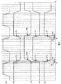
Fig. 8 is the sequential chart of the relation of the analog input signal of expression A/D converter and sampling timing.Among Fig. 8, (a) being the analog input signal waveform, (b) is the master clock signal waveform, (c) is A channeling side sampled clock signal [CLK_A] waveform, (d) is B channeling side sampled clock signal [CLK_A] waveform.Among Fig. 8, with the trailing edge of each sampling clock as sampled point.
In ideal conditions, the sampling of the analog signal of input, the trailing edge of CLK_A carry out the A channeling side sampling (Fig. 8: ●), carry out the sampling (Fig. 8: ▲) of B channeling side at the trailing edge of CLK_B, alternately sample at the A/B channel.At this moment, the sampled point of A/B interchannel is as Fig. 8 ● mark and ▲ shown in the interval between the mark like that, to the analog signal imported for uniformly-spaced.
But, under the situation that adopts clock signal generating device 50 in the past, produce because of the anti-phase delay Δ td that causes between the Q of D-trigger 101 output and NQ output.Therefore, between the trailing edge of the rising edge of CLK_A and CLK_B, between the rising edge of the trailing edge of CLK_A and CLK_B, produce respectively and postpone Δ td.Therefore, the sampled point separately of A/B channel is as Fig. 8 ● shown in mark and zero mark, the analog signal of being imported is not uniformly-spaced, can sample from the analog signal level of desirable sampled point to mistake.Because this A channel and the B signals sampling caused interchannel error of dislocation regularly causes Analog-digital conversion precision deterioration.
Based on above-mentioned background, in order to make the sampling timing in two channels not produce dislocation, and be not subjected to the influence of two interchannel errors, thereby improve Analog-digital conversion precision, wish that having a kind of can phase difference output be the clock signal generating device of two clock signals inverting each other of 180 ° just.And then, wish to have a kind of A/D converting means that adopts this clock signal generating device.
Summary of the invention
The objective of the invention is to,, provide a kind of output to have with the clock forming device of two clock signals of the anti-phase signal waveform of mutually the same timing and the Analog-digital converting means that adopts this generating apparatus in order to solve above-mentioned problem.
Clock signal generating device of the present invention possesses first, second and third d type flip flop,
Above-mentioned first d type flip flop possesses:
The one D input terminal;
First clock input terminal of input clock signal;
First lead-out terminal based on above-mentioned clock signal, keeps giving the input signal and the output of an above-mentioned D input terminal; With
First reversed-phase output based on above-mentioned clock signal, carries out anti-phase and output to the input signal of giving an above-mentioned D input terminal, and with above-mentioned output feedback and be input to an above-mentioned D input terminal,
Above-mentioned second d type flip flop possesses:
The 2nd D input terminal, input is from the output of above-mentioned first lead-out terminal of above-mentioned first d type flip flop;
Import the second clock input terminal of above-mentioned clock signal; With
Second lead-out terminal based on above-mentioned clock signal, keep to be given the input signal of above-mentioned the 2nd D input terminal and is exported as first,
Above-mentioned 3d flip-flop possesses:
The 3rd D input terminal, input is from the output of above-mentioned first reversed-phase output of above-mentioned first d type flip flop;
Import the 3rd clock input terminal of above-mentioned clock signal; With
The 3rd lead-out terminal based on above-mentioned clock signal, keep to be given the input signal of above-mentioned the 3rd D input terminal and is exported as second,
From above-mentioned first output of above-mentioned second lead-out terminal of above-mentioned second d type flip flop with from above-mentioned second output of above-mentioned the 3rd lead-out terminal of above-mentioned 3d flip-flop, have with the anti-phase signal waveform of mutually the same timing.
In addition, above-mentioned second d type flip flop and above-mentioned 3d flip-flop, the timing of the pairing homophase output of clock signal can be identical.
And then, also above-mentioned clock signal generating device can be carried on the IC chip.
Analog-digital converting means of the present invention possesses: above-mentioned clock signal generating device; With the A/D converter, with above-mentioned first output with signal waveform inverting each other and above-mentioned second output that have from above-mentioned clock signal generating device output, come during the switch sampling and during keeping, thereby the analog signal of being imported is transformed to digital signal.
In addition, above-mentioned A/D converter also can possess: A channeling side converter, with between the sampling period of switching the A channeling side from above-mentioned first output of above-mentioned clock signal generating device output and during keeping, thereby the above-mentioned analog signal of being imported is transformed to digital signal; With
B channeling side converter is used and is switched between the sampling period of B channeling side and during keeping from above-mentioned second output of above-mentioned clock signal generating device output, thereby the above-mentioned analog signal of being imported is transformed to digital signal.
In addition, also above-mentioned Analog-digital converting means can be carried on the IC chip.
The invention effect
By clock signal generating device of the present invention and the Analog-digital converting means that adopts this clock signal generating device, three D-triggers have been made up.In first trigger, by with himself NQ output as the input of D input feedback, thereby make master clock signal 1/2 frequency division, export from Q output and NQ, phase difference output is two clock signals of 180 ° roughly.And then, be input to second trigger by Q with first trigger, the NQ of first trigger is input to the 3rd trigger, thus can be with the timing of identical Q output, and phase difference output is two clock signals of 180 ° have signal waveform inverting each other just.
Have again, the A/D converting means of the interleaving access structure by adopting above-mentioned clock signal generating device, can be two clock signals of the waveform of 180 ° have signal inverting each other just with the phase difference of above-mentioned clock signal generating device, be respectively applied for sampling/maintenance switching regularly of A/B channel.Thus, the dislocation of the sampling timing of A/B two interchannels can be eliminated, Analog-digital conversion precision can be improved.
Description of drawings
Fig. 1 is the circuit diagram of the structure of the clock signal generating device of expression embodiments of the present invention 1.
Fig. 2 is the oscillogram of each several part of the clock signal generating device of embodiments of the present invention 1.
Fig. 3 is the piece figure of the structure of the A/D converting means of expression embodiments of the present invention 2.
Fig. 4 is in the A/D of Fig. 3 converter, the circuit diagram when adopting the clock signal generating device of Fig. 1.
Fig. 5 is the analog signal in the A/D converting means of expression embodiments of the present invention 2 and the sequential chart of sampling timing thereof.
Fig. 6 is the circuit diagram of the structure of expression clock signal generating device in the past.
Fig. 7 is the oscillogram of the each several part of clock signal generating device in the past.
Fig. 8 is the analog input signal in the expression A/D converter in the past and the sequential chart of sampling timing thereof.
Among the figure: 1-input end of analog signal; 2-A channeling side A/D converter analog input terminal; 3-A channeling side A/D converter; 4-A channeling side A/D converter digital output terminal; 5-B channeling side A/D converter analog input terminal; 6-B channeling side A/D converter; 7-B channeling side A/D converter digital output terminal; The 8-multiplex electronics; The 9-digital output terminal; The 10-clock signal generating device; 12-A channeling side sampling clock; 13-B channeling side sampling clock; 22-A channeling side sampling clock; 23-B channeling side sampling clock; The 50-clock signal generating device; 91-master clock input terminal; The 100-A/D converting means; 101~103-D-trigger.
Embodiment
Below, describe with the clock signal generating device and the A/D converting means of accompanying drawing embodiments of the present invention.In addition, in the accompanying drawings the identical parts of essence are paid identical symbol.
(execution mode 1)
Fig. 1 is the circuit diagram of the structure of the clock signal generating device 10 of expression embodiments of the present invention 1.This clock signal generating device 10 is made of three D-triggers 101~103.In addition, for input and output, possess master clock signal input terminal 91 and two lead-out terminals 22,23.By two clock signals of two lead- out terminals 22,23 output, these two clock signals phase difference each other be 180 ° and to master clock signal by 1/2 frequency division, and have with the anti-phase signal waveform of identical timing (timing).
Next, the detailed structure to this clock signal generating device 10 describes.
At first, master clock signal input terminal 91 is connected with the clock terminal of a D-trigger 101, the clock terminal of the 2nd D-trigger 102 and the clock terminal of the 3rd D-trigger 103 respectively.In addition, reversed-phase output (NQ) of a D-trigger 101 is connected with the D input terminal of a D-trigger 101 and the D input terminal of the 3rd D-trigger 103.On the other hand, in-phase output end (Q) of a D-trigger 101 is connected with the D input terminal of the 2nd D-trigger 102.
In addition, in-phase output end (Q) of the 2nd D-trigger 102 is connected with lead-out terminal 22, and in-phase output end (NQ) of the 3rd D-trigger 103 is connected with lead-out terminal 23.Under the situation of the A/D converting means of the interleaving access structure that this clock signal generating device is used to have A/B two channels, two outputs can be as A channeling side sampled clock signal and the input of B channeling side sampled clock signal.
In addition, this clock signal generating device 10 also can carry on the IC chip.
Fig. 2 is the oscillogram of the each several part of this clock signal generating device 10.In Fig. 2, (a) be the waveform of master clock signal (MCLK), (b) be homophase output (Q) waveform of a D-trigger 101, (c) be the waveform of the anti-phase output (NQ) of a D-trigger 101, (d) being the waveform [CLK_A] of the homophase output (Q) of the 2nd D-trigger 102, (e) is the waveform [CLK_B] of the homophase output (Q) of the 3rd D-trigger 103.
Next, with reference to Fig. 2, the action of this clock signal generating device 10 is described.
(a) at first, when the trailing edge of moment t1 master clock signal MCLK arrives, if the Q of the D-trigger 101 before moment t1 is output as high level, the NQ of the one D-trigger 101 is output as low level, and then the Q of a D-trigger 101 output (tQ) after t1 is the Δ t time apart from the moment is transferred to low level from high level.And then the NQ output of a D-trigger 101 is being that (Δ t+ Δ td) after the time (tNQ), transfers to high level from low level apart from moment t1.
In addition, between the Q of a D-trigger 101 output and NQ output, there is the delay of Δ td as mentioned above.Therefore between two output, the anti-phase timing Δ td that staggers.
(b) next, in the 2nd D-trigger 102, in the D input terminal of the 2nd D-trigger 102 before moment t1, be transfused to the Q output (high level) of a D-trigger 101.At moment t1, when the trailing edge of master clock signal arrives, the Q of the 2nd D-trigger 102 output, (Q exports regularly: tQ) output high level after t1 is Δ t apart from the moment.
(c) in the 3rd D-trigger 103, in the D input terminal of the 3rd D-trigger 103 before moment t1, be transfused to the NQ output (low level) of a D-trigger 101.When the trailing edge of moment t1 master clock signal arrives, the Q output of the 3rd D-trigger 103, (Q exports regularly: tQ) output low level after t1 is the Δ t time apart from the moment.
As mentioned above, this clock signal generating device 10 is with the D input input of the Q of a D-trigger 101 output as second trigger 102, with the NQ output of the first trigger 101 D input input as the 3rd trigger 103.Exist between the Q output of first trigger 101 and the NQ output and postpone Δ td, but the second and the 3rd trigger 102,103 that has the timing of identical Q output by employing can be exported two clock signals conducts Q output separately, these two clock signals are that master clock signal is by 1/2 frequency division, phase difference is 180 ° just, and has signal waveform inverting each other.
Below, to by adopting second and third trigger 102,103, as Q output separately, phase difference output is that 180 ° and mechanism with two clock signals of signal waveform inverting each other are described in detail just.
At this, trailing edge (Fig. 2: the state before arrival moment t1) at master clock signal MCLK, be input to the 2nd D-trigger 102 the D input terminal a D-trigger 101 Q output signal (Fig. 2: (b)) and be input to the NQ output signal (Fig. 2: (c)) of a D-trigger 101 of the D input terminal of the 3rd D-trigger 103, determine.And then, second trigger 102 and the 3rd trigger 103 are identical from the timing till Q output (tQ: from moment t1 after the Δ t time) that arrives of the trailing edge of clock signal.Therefore, when the trailing edge of master clock signal MCLK arrives, from the Q output signal 22 of the 2nd D-trigger 102 with from the Q output signal 23 of the 3rd D-trigger 103, as the timing of identical Q output, played the Δ t time at moment t1 forthwith mutually after output respectively.Also have in addition, the delay Δ td between the Q of first trigger 101 output and the NQ output is more small, and the value of each signal of (Fig. 2: t1) constantly was the combination of reciprocal value (high level, low level, or low level, high level) when trailing edge arrived.Therefore, from the Q output signal 22 of the 2nd D-trigger 102 with from the Q output signal 23 of the 3rd D-trigger 103, have two clock signals of signal waveform inverting each other with timing (tQ) output of identical Q output.
By the clock signal generating device 10 of embodiments of the present invention 1, can export master clock input signal 1/2 frequency division, and phase difference is two clock signals of 180 ° have signal waveform inverting each other just.
(execution mode 2)
Fig. 3 is the module map of the structure of Analog-digital (A/D) converting means 100 of the interleaving access structure of expression embodiments of the present invention 2.Fig. 4 for expression as the clock signal generating device 10 of Fig. 3, the module map of the detailed structure when adopting the clock signal generating device 10 of execution mode 1.This A/D converting means 100 is characterised in that to possess the clock signal generating device 10 of embodiments of the present invention 1.Have, this A/D converting means 100 possesses (A channeling side) A/D converter 3, the opposing party's side (B channeling side) A/D converter 6, multiplex electronics 8, digital signal output end 9 of clock signal generating device 10, input end of analog signal 1, side's side again.The structure of clock signal generating device 10, identical with embodiments of the present invention 1 clock signal generating device 10 shown in Figure 1, therefore omit its explanation.
A channeling side A/D converter 3 has A channeling side input end of analog signal 2 and A channeling side digital signal output end 4, and it 6 has B channeling side input end of analog signal 5 and B channeling side digital signal output end 7 B channeling side A/D conversion.
In addition, this Analog-digital converting means 100 also can carry on the IC chip.
Next, the action to the A/D converting means of the interleaving access structure that constitutes as shown in Figure 3 describes.
(a) be imported into the analog signal of input end of analog signal, be imported into input end of analog signal 2 of A channeling side and input end of analog signal 5 of B channeling side.
(b) be imported into the analog signal of input end of analog signal 2 of A channeling side, the A/D converter 3 by the A channeling side is transformed to digital signal from analog signal A/D, from the digital signal output end 4 output digital signals of A channeling side.
(c) same, be imported into the analog signal of input end of analog signal 5 of B channeling side, the A/D converter 6 by the B channeling side is transformed to digital signal from analog signal by A/D, from the digital signal output end 7 output digital signals of B channeling side.
(d) from the digital signal of the digital signal output end of A channeling side 4 outputs with from the digital signal of digital signal output end 7 outputs of B channeling side, synthetic by multiplex electronics 8, from digital signal output end 9 output digital signals.
Have again, the sampling timing of A/B two channels in this A/D converting means 100 is described.
(a) be input to the master clock signal of master clock signal input terminal 91, by 1/2 frequency division, generate the sampled clock signal of A channeling side and the sampled clock signal of B channeling side by clock signal generating device 10.
(b) from the sampled clock signal of the sampled clock signal lead-out terminal 22 output A channeling sides of A channeling side, from the sampled clock signal lead-out terminal 23 output B channeling side sampled clock signals of B channeling side.In addition, as mentioned above, the sampled clock signal of the sampled clock signal of A channeling side and B channeling side is the relation with the signal waveform of (phase place differs 180 ° just) inverting each other.
(c) sampled clock signal [CLK_A] by the A channeling side carries out between the sampling period of A/D converter 3 of A channeling side and the switching during keeping, and the sampled clock signal [CLK_B] by the B channeling side carries out between the sampling period of A/D converter 6 of B channeling side and the switching during keeping.
In this A/D converting means 100, the clock signal generating device 10 of employing and execution mode 1 carries out 1/2 frequency division with the master clock input signal, and obtaining phase difference is two clock signals of 180 ° have signal waveform inverting each other just.For sampling/maintenance timing of switching A/B two channels, can adopt this two clock signals respectively.Thus, in this A/D converting means 100, do not produce the error of the sampling timing in A/B two channels, and can improve the equally spaced Analog-digital conversion precision that is spaced apart of the sampling timing that makes two interchannels.
Fig. 5 is the sequential chart of the relation of analog input (analog in) signal of A/D converting means 100 of expression embodiments of the present invention 2 and its sampling timing.In Fig. 5, (a) be the analog input signal waveform, (b) be master-clock signal waveform, (c) be A channeling side sampled clock signal [CLK_A] waveform, (d) be B channeling side sampled clock signal [CLK_B] waveform.
To in this A/D converting means 100, the equally spaced mechanism that is spaced apart of the sampling timing of A/B two interchannels is described with Fig. 5.In Fig. 5, with the trailing edge of each sampling clock as sampled point.
As mentioned above, the sampled clock signal [CLK_A] and the B channeling side sampled clock signal [CLK_B] of the A channeling side that generates by clock signal generating device 10, phase difference is 180 ° just and has signal waveform inverting each other.Therefore, the rising edge of CLK_A is consistent with the trailing edge of CLK_B, and the rising edge of the trailing edge of CLK_A and CLK_B is consistent.That is, the trailing edge from the trailing edge of CLK_B (Fig. 5: ▲) to CLK_A (Fig. 5: ●) time (Δ t
BA) and from the trailing edge of CLK_A (Fig. 5: ●) to time (the Δ t of the trailing edge of CLK_B (Fig. 5: ▲)
AB) have the identical time interval, can generation time not poor.Therefore, in this A/D converting means 100, the sampling of the analog signal of being imported, the trailing edge of CLK_A (Fig. 5: ●) and the trailing edge of CLK_B (Fig. 5: ▲) by alternating sampling, as shown in Figure 5, each sampled point with respect to the analog signal of being imported for uniformly-spaced.Thus,, the sampling timing of A/B two interchannels is had uniformly-spaced, can improve Analog-digital conversion precision by eliminating each the dislocation of sampling timing of A channel and B channel.
Utilize possibility on the industry
Clock signal generating device of the present invention, effective in by the A/D converting means of interleaving access structure action.
Claims (3)
1. an A/D commutator is characterized in that,
Possess clock signal generating device,
This clock signal generating device possesses first, second and third d type flip flop,
Above-mentioned first d type flip flop possesses:
The one D input terminal;
First clock input terminal of input clock signal;
First lead-out terminal based on above-mentioned clock signal, keeps giving the input signal and the output of an above-mentioned D input terminal; With
First reversed-phase output based on above-mentioned clock signal, carries out anti-phase and output to the input signal of giving an above-mentioned D input terminal, and above-mentioned output feedback is input to an above-mentioned D input terminal,
Above-mentioned second d type flip flop possesses:
The 2nd D input terminal, input is from the output of above-mentioned first lead-out terminal of above-mentioned first d type flip flop;
Import the second clock input terminal of above-mentioned clock signal; With
Second lead-out terminal based on above-mentioned clock signal, keep to be given the input signal of above-mentioned the 2nd D input terminal and is exported as first,
Above-mentioned 3d flip-flop possesses:
The 3rd D input terminal, input is from the output of above-mentioned first reversed-phase output of above-mentioned first d type flip flop;
Import the 3rd clock input terminal of above-mentioned clock signal; With
The 3rd lead-out terminal based on above-mentioned clock signal, keep to be given the input signal of above-mentioned the 3rd D input terminal and is exported as second,
From above-mentioned first output of above-mentioned second lead-out terminal of above-mentioned second d type flip flop with from above-mentioned second output of above-mentioned the 3rd lead-out terminal of above-mentioned 3d flip-flop, have with the anti-phase signal waveform of mutually the same timing,
Above-mentioned second d type flip flop and above-mentioned 3d flip-flop, the timing of the pairing homophase output of clock signal is identical,
Above-mentioned A/D commutator, also possesses the A/D converter, with above-mentioned first output with signal waveform inverting each other and above-mentioned second output that have from above-mentioned clock signal generating device output, come during the switch sampling and during keeping, thereby the analog signal of being imported is transformed to digital signal.
2. A/D commutator according to claim 1 is characterized in that,
Above-mentioned A/D converter possesses:
A channeling side converter is used and is switched between the sampling period of A channeling side and during keeping from above-mentioned first output of above-mentioned clock signal generating device output, thereby the above-mentioned analog signal of being imported is transformed to digital signal; With
B channeling side converter is used and is switched between the sampling period of B channeling side and during keeping from above-mentioned second output of above-mentioned clock signal generating device output, thereby the above-mentioned analog signal of being imported is transformed to digital signal.
3. an IC chip is equipped with the described above-mentioned A/D commutator of claim 1.
Applications Claiming Priority (3)
| Application Number | Priority Date | Filing Date | Title |
|---|---|---|---|
| JP2006351203 | 2006-12-27 | ||
| JP2006351203A JP2008166910A (en) | 2006-12-27 | 2006-12-27 | Clock signal generator and analog/digital converter |
| JP2006-351203 | 2006-12-27 |
Publications (2)
| Publication Number | Publication Date |
|---|---|
| CN101212213A CN101212213A (en) | 2008-07-02 |
| CN101212213B true CN101212213B (en) | 2011-11-23 |
Family
ID=39583125
Family Applications (1)
| Application Number | Title | Priority Date | Filing Date |
|---|---|---|---|
| CN2007101993543A Active CN101212213B (en) | 2006-12-27 | 2007-12-17 | Analog-digital conversion device and IC chip |
Country Status (3)
| Country | Link |
|---|---|
| US (1) | US7609194B2 (en) |
| JP (1) | JP2008166910A (en) |
| CN (1) | CN101212213B (en) |
Families Citing this family (8)
| Publication number | Priority date | Publication date | Assignee | Title |
|---|---|---|---|---|
| US8749419B2 (en) * | 2009-08-11 | 2014-06-10 | Hittite Microwave Corporation | ADC with enhanced and/or adjustable accuracy |
| PL220358B1 (en) * | 2012-01-31 | 2015-10-30 | Akademia Górniczo Hutnicza Im Stanisława Staszica W Krakowie | Method and system for no timer conversion of the electric voltage to the digital word |
| CN105144579B (en) * | 2013-03-15 | 2018-06-01 | 高通股份有限公司 | Low power architecture |
| JP6127807B2 (en) * | 2013-07-26 | 2017-05-17 | 富士通株式会社 | Transmission circuit, communication system, and communication method |
| KR102432457B1 (en) * | 2015-10-21 | 2022-08-12 | 삼성전자주식회사 | Clock Generation Circuit having De-skew function and Semiconductor Integrated Circuit Device including the same |
| WO2017154191A1 (en) * | 2016-03-11 | 2017-09-14 | 株式会社ソシオネクスト | Divider circuit, demultiplexer circuit, and semiconductor integrated circuit |
| US10790845B1 (en) * | 2019-05-31 | 2020-09-29 | The Boeing Company | Clocking circuit and method for time-interleaved analog-to-digital converters |
| CN112202446B (en) * | 2019-07-08 | 2024-06-14 | 北京三中科技有限公司 | Phase synchronization device and method |
Citations (4)
| Publication number | Priority date | Publication date | Assignee | Title |
|---|---|---|---|---|
| CN1186384A (en) * | 1996-11-21 | 1998-07-01 | 松下电器产业株式会社 | A/D converter and converting method |
| CN1340247A (en) * | 1999-12-17 | 2002-03-13 | 酒井康江 | Oversampling circuit and digital/analog converter |
| CN1431778A (en) * | 1995-09-05 | 2003-07-23 | 三菱电机株式会社 | Trigger circuit |
| US6771202B2 (en) * | 2002-04-24 | 2004-08-03 | Denso Corporation | Analog-to-digital conversion method and device |
Family Cites Families (10)
| Publication number | Priority date | Publication date | Assignee | Title |
|---|---|---|---|---|
| US5552732A (en) * | 1995-04-25 | 1996-09-03 | Exar Corporation | High speed divide by 1.5 clock generator |
| US5808691A (en) * | 1995-12-12 | 1998-09-15 | Cirrus Logic, Inc. | Digital carrier synthesis synchronized to a reference signal that is asynchronous with respect to a digital sampling clock |
| JP3467975B2 (en) | 1996-06-27 | 2003-11-17 | 安藤電気株式会社 | Phase detection circuit |
| JP2000216762A (en) | 1999-01-26 | 2000-08-04 | Hitachi Denshi Ltd | Sampling frequency conversion circuit |
| JP2001217886A (en) | 2000-01-31 | 2001-08-10 | Matsushita Electric Ind Co Ltd | Phase shifter |
| US6642747B1 (en) * | 2002-03-15 | 2003-11-04 | National Semiconductor Corporation | Frequency detector for a phase locked loop system |
| EP1544630B1 (en) * | 2003-12-17 | 2008-05-14 | STMicroelectronics Limited | TAP time division multiplexing |
| DE602005018114D1 (en) * | 2005-03-31 | 2010-01-14 | Freescale Semiconductor Inc | PROCESS FOR NOISE REDUCTION IN A PHASE CONTROL ARC AND DEVICE WITH NOISE REDUCTIONS |
| US7515666B2 (en) * | 2005-07-29 | 2009-04-07 | International Business Machines Corporation | Method for dynamically changing the frequency of clock signals |
| KR100808055B1 (en) * | 2006-10-31 | 2008-02-28 | 주식회사 하이닉스반도체 | Delay locked loop of semiconductor device and operation method thereof |
-
2006
- 2006-12-27 JP JP2006351203A patent/JP2008166910A/en active Pending
-
2007
- 2007-12-17 CN CN2007101993543A patent/CN101212213B/en active Active
- 2007-12-27 US US11/964,943 patent/US7609194B2/en active Active
Patent Citations (4)
| Publication number | Priority date | Publication date | Assignee | Title |
|---|---|---|---|---|
| CN1431778A (en) * | 1995-09-05 | 2003-07-23 | 三菱电机株式会社 | Trigger circuit |
| CN1186384A (en) * | 1996-11-21 | 1998-07-01 | 松下电器产业株式会社 | A/D converter and converting method |
| CN1340247A (en) * | 1999-12-17 | 2002-03-13 | 酒井康江 | Oversampling circuit and digital/analog converter |
| US6771202B2 (en) * | 2002-04-24 | 2004-08-03 | Denso Corporation | Analog-to-digital conversion method and device |
Also Published As
| Publication number | Publication date |
|---|---|
| JP2008166910A (en) | 2008-07-17 |
| CN101212213A (en) | 2008-07-02 |
| US20080158035A1 (en) | 2008-07-03 |
| US7609194B2 (en) | 2009-10-27 |
Similar Documents
| Publication | Publication Date | Title |
|---|---|---|
| CN101212213B (en) | Analog-digital conversion device and IC chip | |
| US8760325B2 (en) | Scheme for balancing skew between lanes of high-speed serial digital interface | |
| Razavi | Problem of timing mismatch in interleaved ADCs | |
| US10291245B2 (en) | Device and method for correcting error estimation of analog-to-digital converter | |
| EP2965430B1 (en) | Configurable time-interleaved analog-to-digital converter | |
| US9270292B2 (en) | Efficient time-interleaved analog-to-digital converter | |
| EP2618490A2 (en) | Pipelined analog-to-digital converter having reduced power consumption | |
| CN109728818A (en) | Tracking and holding circuit for high speed and staggered ADC | |
| WO2004079917A1 (en) | Method and device for estimating time errors in time interleaved a/d converter system | |
| CN109032498B (en) | Waveform quantization synchronization method of multi-FPGA multi-channel acquisition system | |
| CN108233906B (en) | Starting-up deterministic delay system and method based on ADC | |
| Naraghi et al. | A 9b 14µw 0.06 mm 2 ppm adc in 90nm digital cmos | |
| CN101753141B (en) | Multichannel analog-to-digital conversion digital synchronous sampling method | |
| KR101922018B1 (en) | Multichannel analog to digital converter apparatus and method for using | |
| CN104283561A (en) | Asynchronous clock parallel-serial conversion half-cycle output circuit | |
| JP2018125838A (en) | High-speed and low-power digital / analog upconverter | |
| CN108333910B (en) | Novel time-to-digital converter | |
| EP3776862A1 (en) | Systems and methods for performing analog-to-digital conversion across multiple, spatially separated stages | |
| JP2000354026A (en) | Clock signal generator for generating sub-sampling clock signal having edge of high timing accuracy at high speed | |
| CN112019215A (en) | Pulse width modulation single-distribution type multi-channel ADC synchronization method | |
| CN111641414A (en) | DAC multi-chip synchronization design based on group delay filter | |
| JP2017143411A (en) | Time interleave type ad conversion device, reception device and communication device | |
| EP3547546A1 (en) | Systems and methods for performing analog-to-digital conversion across multiple, spatially separated stages | |
| CN103095304A (en) | Homodromous orthogonal signal analog-digital converter | |
| CN117459064B (en) | Multipath ADC sampling method, device and equipment |
Legal Events
| Date | Code | Title | Description |
|---|---|---|---|
| C06 | Publication | ||
| PB01 | Publication | ||
| C10 | Entry into substantive examination | ||
| SE01 | Entry into force of request for substantive examination | ||
| C14 | Grant of patent or utility model | ||
| GR01 | Patent grant | ||
| TR01 | Transfer of patent right | ||
| TR01 | Transfer of patent right |
Effective date of registration: 20200603 Address after: Kyoto Japan Patentee after: Panasonic semiconductor solutions Co.,Ltd. Address before: Osaka Japan Patentee before: Panasonic Corp. |