CN100578659C - Synchronous flash memory with status burst output - Google Patents
Synchronous flash memory with status burst output Download PDFInfo
- Publication number
- CN100578659C CN100578659C CN01816420A CN01816420A CN100578659C CN 100578659 C CN100578659 C CN 100578659C CN 01816420 A CN01816420 A CN 01816420A CN 01816420 A CN01816420 A CN 01816420A CN 100578659 C CN100578659 C CN 100578659C
- Authority
- CN
- China
- Prior art keywords
- data
- register
- read
- status
- clock
- Prior art date
- Legal status (The legal status is an assumption and is not a legal conclusion. Google has not performed a legal analysis and makes no representation as to the accuracy of the status listed.)
- Expired - Fee Related
Links
Images


Classifications
-
- G—PHYSICS
- G11—INFORMATION STORAGE
- G11C—STATIC STORES
- G11C7/00—Arrangements for writing information into, or reading information out from, a digital store
- G11C7/10—Input/output [I/O] data interface arrangements, e.g. I/O data control circuits, I/O data buffers
- G11C7/1015—Read-write modes for single port memories, i.e. having either a random port or a serial port
- G11C7/103—Read-write modes for single port memories, i.e. having either a random port or a serial port using serially addressed read-write data registers
-
- G—PHYSICS
- G11—INFORMATION STORAGE
- G11C—STATIC STORES
- G11C11/00—Digital stores characterised by the use of particular electric or magnetic storage elements; Storage elements therefor
- G11C11/21—Digital stores characterised by the use of particular electric or magnetic storage elements; Storage elements therefor using electric elements
- G11C11/34—Digital stores characterised by the use of particular electric or magnetic storage elements; Storage elements therefor using electric elements using semiconductor devices
- G11C11/40—Digital stores characterised by the use of particular electric or magnetic storage elements; Storage elements therefor using electric elements using semiconductor devices using transistors
-
- G—PHYSICS
- G11—INFORMATION STORAGE
- G11C—STATIC STORES
- G11C7/00—Arrangements for writing information into, or reading information out from, a digital store
- G11C7/10—Input/output [I/O] data interface arrangements, e.g. I/O data control circuits, I/O data buffers
- G11C7/1015—Read-write modes for single port memories, i.e. having either a random port or a serial port
- G11C7/1018—Serial bit line access mode, e.g. using bit line address shift registers, bit line address counters, bit line burst counters
-
- G—PHYSICS
- G11—INFORMATION STORAGE
- G11C—STATIC STORES
- G11C7/00—Arrangements for writing information into, or reading information out from, a digital store
- G11C7/10—Input/output [I/O] data interface arrangements, e.g. I/O data control circuits, I/O data buffers
- G11C7/1072—Input/output [I/O] data interface arrangements, e.g. I/O data control circuits, I/O data buffers for memories with random access ports synchronised on clock signal pulse trains, e.g. synchronous memories, self timed memories
-
- G—PHYSICS
- G11—INFORMATION STORAGE
- G11C—STATIC STORES
- G11C16/00—Erasable programmable read-only memories
- G11C16/02—Erasable programmable read-only memories electrically programmable
- G11C16/06—Auxiliary circuits, e.g. for writing into memory
- G11C16/10—Programming or data input circuits
- G11C16/20—Initialising; Data preset; Chip identification
-
- G—PHYSICS
- G11—INFORMATION STORAGE
- G11C—STATIC STORES
- G11C16/00—Erasable programmable read-only memories
- G11C16/02—Erasable programmable read-only memories electrically programmable
- G11C16/06—Auxiliary circuits, e.g. for writing into memory
- G11C16/22—Safety or protection circuits preventing unauthorised or accidental access to memory cells
-
- G—PHYSICS
- G11—INFORMATION STORAGE
- G11C—STATIC STORES
- G11C16/00—Erasable programmable read-only memories
- G11C16/02—Erasable programmable read-only memories electrically programmable
- G11C16/06—Auxiliary circuits, e.g. for writing into memory
- G11C16/26—Sensing or reading circuits; Data output circuits
Abstract
Synchronous flash memory comprises array of non-volatile memory cells.Memory array is aligned to row and column, and can further be arranged in addressable.Data communication connect be used for external unit (such as, processor or other Memory Controllers) carry out bidirectional data communication.Storer can be in the data of exporting on data communication connects during a series of clock period from storage register, so that the train of impulses of register data to be provided.Storer can clock latency value according to the rules provide register data.Register data can comprise status data, operation setting Value Data, make identification and storage component part identification.
Description
Technical field
The present invention relates generally to nonvolatile memory device, particularly, the present invention relates to synchronous non-volatile flash memory.
Background technology
Storage component part typically is provided the internal storage areas that is used as in the computing machine.Term memory represents to have the data storage of integrated circuit (IC) chip form.Storer has several different types.One type is RAM (random access memory).This typically is used as the primary memory under the computer environment.RAM is meant and reads and write store, just, can write data into RAM and from the RAM sense data.These are different with ROM, and ROM only allows sense data.Most of RAM are volatibility, this means that it needs stable electric current to keep its content, need only power supply by deactivation, and whatsoever data are all lost in RAM.
Computing machine almost always comprises ROM (read-only memory) (ROM) in a small amount, and it preserves the instruction that is used to activate computing machine.Different with RAM, ROM can not be written into.EEPROM (EEPROM (Electrically Erasable Programmable Read Only Memo)) is a kind of non-volatile ROM of specific type, and it can be wiped free of by it is exposed in the electric charge.As the ROM of other types, EEPROM does not have RAM fast like that traditionally.EEPROM comprise big figure very, have a storage unit of the grid (floating gate) that electricity isolates.Data are that the form with the electric charge on the floating gate is stored in storage unit.By programming and erase operation, electric charge is transported to floating gate respectively or is removed from floating gate.
The nonvolatile memory of another kind of type is a flash memory.Flash memory is a kind of EEPROM, and it can be with the form of piece, rather than next byte ground, is wiped free of and reprogramming.The PCS in many modern times have they, be stored in the BIOS on the flash memory chip, like this, if necessary it can easily be updated.Such BIOS is called as fast B IOS sometimes.Flash memory is also very general in modulator-demodular unit, because it makes the modem manufacturer can support new agreement (when these agreements become standardization).
Typical flash memory comprises memory array, and it comprises storage unit big figure very, that arrange with the form of row and column.Each storage unit comprise can keep electric charge, the floating gate field effect transistor.Storage unit is organized as piece usually.Each unit in a piece can be by floating gate is charged by electricity programming randomly.By the piece erase operation, electric charge can be removed from floating gate.By the existence of the electric charge on the floating gate whether and be determined data in the storage unit be.
Synchronous dram (SDRAM) is a kind of DRAM, and it can be with the clock speed operation more much higher than traditional DRAM storer.SDRAM makes itself and cpu bus synchronous, and can move with 100MHz speed, than fast approximately three times of traditional FPM (fast page mode) RAM, and the twice that is about quick EDO (growth data output) DRAM and BEDO (output of train of impulses growth data) DRAM.Access sdram promptly, but it is a volatibility.Many computer systems are designed to be used in SDRAM and operate, and acquire benefit from nonvolatile memory.
Because above-mentioned reason, and because other reasons of setting forth below, these reasons will be conspicuous after reading and the explanation of understanding present technique for those skilled in the art, need a kind of can operate in the mode that is similar to the SDRAM operation, nonvolatile memory device in present technique.
Summary of the invention
The above-mentioned problem and the other problems of storage component part are solved by the present invention, and can understand them by the technical descriptioon of reading and research is following.
In one embodiment, the method of operation synchronous memories device comprises the read pulse string length of determining x cycle so that be output with the individual clock period in succession of x from the data output of synchronous memories device, the starting register read, so that read the data that are stored in the internal register, and in x clock period in succession, on connecting, external data exports the data that are stored in the internal register.
In another embodiment, the method for operation synchronous memories device comprises accepts the read register order, and exports register data from the synchronous memories device in response to the read register order in x clock period.
In another embodiment, the method for operation synchronous memories device is included on the array of storage component part and carries out write operation, and during carrying out write operation, the register read order of from processor is provided to storage component part.Input end at storage component part is accepted in first clock period in the register read order, and the register data that is stored in the memory register is read out.Register data was output in the data communication connection at the synchronous memories device during a plurality of clock period.The output of register data after receive the register read order, delayed time predetermined clock latency at interval.
The synchronous memories device comprises that memory cell array, data register and clock signal input connect.Control circuit provides data from data register in response to the register read order in the output junction.Control circuit is according to read pulse string length value output data in the clock period of predetermined number of programming.
According to an aspect of the present invention, provide a kind of method of operating the synchronous memories device, comprising:
In mode register, determine the read pulse string length in x cycle, so that the data of exporting were output with x clock period in succession from the status register of synchronous memories device;
The starting register read is so that read the data that are stored in the status register; And
In x clock period in succession, on connecting, external data exports the data that are stored in the status register,
Described method also comprises the clock latency of determining y cycle, so that y the clock period of data after the starting register read that is stored in the status register is output.
According to a further aspect in the invention, provide a kind of method of operating the synchronous memories device, comprising:
Receive the read states register command; And
In x clock period, export status register data in response to this read register order from the synchronous memories device,
Wherein y the clock period of status register data after receiving this read register order is output.
According to a further aspect in the invention, provide a kind of method that reads out in the register data in the synchronous memories device, comprising:
The status register read command of from processor is provided to storage component part;
On the input end of first clock period, receive this register read order at storage component part;
Read the status register data that are stored in the memory register;
Connecting these status register data of output in the data communication of synchronous memories device during two after described first clock period or clock cycle more for a long time, wherein the output of these status register data clock latency interval of a storage of after receiving the register read order, having been delayed time.
According to a further aspect in the invention, provide a kind of method of operating the synchronous memories device, comprising:
Array to storage component part is carried out write operation;
During carrying out write operation, a status register read command of from processor is provided to storage component part;
On the input end of first clock period, receive this status register read command at storage component part;
Read the status register data that are stored in the memory register;
Connecting these status register data of output in the data communication of synchronous memories device during two after described first clock period or clock cycle more for a long time, wherein the output of these status register data clock latency interval of a storage of after receiving this status register read command, having been delayed time.
According to a further aspect in the invention, provide a kind of synchronous memories device, comprising:
Memory cell array;
Control circuit;
The clock signal input that is input to this control circuit connects; And
Be connected the status data register between this memory cell array and the control circuit;
Wherein this control circuit provides data from this status data register in response to the external register read command on the DOL Data Output Line of the storage component part that is connected to this memory cell array, and this control circuit is being programmed these data of output in the clock period of number according to the read pulse string length value of programming.
According to a further aspect in the invention, provide a kind of disposal system, comprising:
Processor; And
Be coupled to the non-volatile synchronous memories device of processor, it comprises,
Memory cell array,
Control circuit;
The clock signal input that is input to this control circuit connects; And
Be connected the status data register between this memory cell array and the control circuit;
Wherein this control circuit provides data from this status data register in response to the external register read command on the DOL Data Output Line of the storage component part that is connected to this memory cell array, and this control circuit is being programmed these data of output in the clock period of number according to the read pulse string length value of programming.
Description of drawings
Figure 1A is the block scheme of synchronous flash memory of the present invention;
Figure 1B is the interconnected figure of the ic pin of one embodiment of the present of invention;
Fig. 1 C is the interconnected salient point grid array of the integrated circuit of one embodiment of the present of invention (bumpgiid array) figure;
Fig. 2 represents the mode register of one embodiment of the present of invention;
Fig. 3 represents to have the read operation of the CAS stand-by period of one, two and three clock period;
Fig. 4 represents to activate a specific row in a group of the storer of one embodiment of the present of invention;
Fig. 5 is illustrated in the order of work and reads or writes sequential between the order;
Fig. 6 represents read command;
Fig. 7 represents the sequential of the read pulse string in succession of one embodiment of the present of invention;
Fig. 8 is illustrated in the interior read access at random of one page of one embodiment of the present of invention;
Fig. 9 represents that the back follows the read operation of write operation;
Figure 10 represents according to read pulse string operation one embodiment of the present of invention, by using the order of train of impulses termination to terminate;
Figure 11 represents write order;
Figure 12 represents that the back follows the write operation of read operation;
Figure 13 represents that the power of one embodiment of the present of invention reduces operation;
Figure 14 is illustrated in clock hang up between the train of impulses reading duration;
Figure 15 represents to have the storage address conversion of an embodiment of the storer of two guiding sectors;
Figure 16 is according to the process flow diagram of the write sequence of one embodiment of the present of invention, self-timing;
Figure 17 is according to one embodiment of the present of invention, the complete process flow diagram of writing the thermodynamic state verification sequence;
Figure 18 wipes the process flow diagram of sequence according to the piece of one embodiment of the present of invention, self-timing;
Figure 19 is according to the process flow diagram of one embodiment of the present of invention, complete piece erase status checking sequence;
Figure 20 is according to the process flow diagram of one embodiment of the present of invention, block protection sequence;
Figure 21 is according to the process flow diagram of one embodiment of the present of invention, complete bulk state checking sequence;
Figure 22 is according to the process flow diagram of one embodiment of the present of invention, device protection sequence;
Figure 23 is according to the process flow diagram of the non-protection sequence of one embodiment of the present of invention, piece;
Figure 24 represents to start the sequential with the loading pattern register manipulation;
Figure 25 represents the sequential of clock suspending mode operation;
The sequential of Figure 26 indicating impulse string read operation;
Figure 27 represents that alternate group reads the sequential of visit;
Figure 28 represents the sequential of full page train of impulses read operation;
Figure 29 represents the sequential by the train of impulses read operation of using the data mask signal;
The sequential to the write operation of not reading is on the same group followed in Figure 30 table back;
Figure 31 represents that the back follows the sequential to the same group of write operation of reading;
Figure 32 represents accumulator system of the present invention; And
Figure 33 represents multicomputer system of the present invention.
Embodiment
In the detailed explanation below of the present invention,, and wherein shown and to have implemented certain embodiments of the present invention with reference to the accompanying drawing that constitutes a part of the present invention.These embodiment fully at length are described, so that those skilled in the art can implement the present invention, and it will be appreciated that, can utilize other embodiment and can make logic, machinery with the change of electricity, and do not deviate from the spirit and scope of the present invention.So following detailed description is not to make in limiting sense, and scope of the present invention only is defined by the claims.
Following detailed description is divided into two main joints.First segment is the interface function explanation, and it elaborates the compatibility with the SDRAM storer.Second joint is a functional description, and it specifies the functional order of flash structures.
The interface function explanation
With reference to Figure 1A, the block scheme of one embodiment of the present of invention is described.Storage component part 100 comprises the array of non-volatile flash memory 102.Array is aligned to a plurality of addressable group.In one embodiment, storer comprises four memory set 104,106,108 and 110.Each memory set comprises addressable sector of storage unit.The data that are stored in the storer can be accessed by using by address register 112 location address that accept, that the outside provides.Utilize row address multiplex circuit 114, these addresses are deciphered.These addresses also can be decoded by use group steering logic 116 and row address latch and decoding scheme 118.For the suitable row of reference-to storage, column address counter and latch cicuit 120 are coupled to array decoding circuit 122 to the address of accepting.Circuit 124 provides I/O gating, data mask logic, read data latch cicuit and write driver circuit.Data are transfused to by data input register 126 and are output by data output register 128.Command execution logic 130 is provided to the basic operation of control store device.State machine 132 also is provided to be controlled at the specific operation of carrying out on memory array and the unit.Status register 134 and identification register 136 also can be provided to output data.
Figure 1B represents the interconnected pin assignments of one embodiment of the present of invention.Memory package 150 has 54 interconnected pins.Mount structure is substantially similar to available SDRAM encapsulation.For two specific interconnected pins of the present invention is RP# 152 and Vccp 154.It seems and the identical interconnected label of SDRAM that though the present invention can share the function of the signal that provides is described here on interconnected pin, unless and set forth here, it should not be equal to the function of the signal of SDRAM.Fig. 1 C represents an embodiment of memory package 160, and it has the projection connection, rather than the pin of Fig. 1 C connects.So the present invention is not limited to specific encapsulating structure.
Before the operating characteristic of describing storage component part, provide the more detailed description of interconnected pin and their each signal earlier.The input clock connection is used for providing clock signal (CLK).Clock signal can be driven by system clock, and all synchronous flash memory input signals are sampled at the rising edge place of CLK.CLK also adds increment to internal pulses string counter, and the control output register.
Input clock allows (CKE) link to be used for activating (HIGH (height) state) and the input of deactivation (LOW (low) state) CLK signal.The input of deactivation clock can provide power to reduce and wait for operation (all memory set are idle) herein, the power of work reduces (memory lines is ACTIVE (work) in any group), or clock hang up (train of impulses/visit is underway).CKE is synchronous, unless after device ingoing power reduction pattern, herein CKE become asynchronous, till withdrawing from after this pattern.Input buffer comprises CLK, is forbidden during power reduction pattern, so that low wait power is provided.CKE can maintain HIGH (height) in required power not reduces the system of pattern (being different from RP# degree of depth power reduces).
Chip selects (CS#) input link that a signal is provided, so that allow (LOW that deposits (low)) and forbid the command decoder that (HIGH that deposits (height)) provides in command execution logic.All order conductively-closed when CS# is deposited to HIGH.In addition, CS# provides outside group selection having in a plurality of groups the system, and CS# can be looked at as the part of command code; But it is not necessarily necessary.
The input command input link regulation that is used for RAS#, CAS# and WE# (together with CAS#, CS#) will be stored the order that device is carried out, as detailed hereafter.The output that I/O shielding (DQM) link is used for being provided for the input shielded signal of write access and being used for read access allows signal.When DQM is sampled HIGH during write cycle time, the conductively-closed of input data.When DQM was sampled HIGH during the read cycle, output buffer was placed in the high impedance (state (behind two clock latencies) of height-Z).DQML connects DQ0-DQ7 corresponding to data, and DQMH connects DQ8-DQ15 corresponding to data.DQML is considered to identical state with DQMH when being expressed as DQM.
Input resets/and power reduces (RP#) and connects 140 and be used in and reset and power reduces operation.When initial device power rose, in one embodiment, before sending executable order, RP# needed later 100 μ s time-delay from the low height of transferring to, so that the internal components initialization.RP# signal removal status register is arranged on the array reading mode to internal state machine (ISM) 132, and when being in LOW (low), places device degree of depth power to reduce pattern.During power reduction pattern, all inputs connect, and comprise CS# 142, all be in " need not manage it ", and all output are in High-Z (high resistant) state.When the RP# signal equaled VHH voltage (5 volts), during WRITE and ERASE, all protected modes were left in the basket.The RP# signal also allows device protection bit to be set to 1 (protection) and allows the block protection bit of 16 bit register (in the position 0 and 15) to be set to 0 (non-protection), when being coupled with VHH.The protection bit will be described below in more detail.During every other operator scheme, RP# is retained as HIGH.
The group address input connects, and BA0 and BA1 stipulate which group adds ACTIVE, READ, WRITE or BLOCK PROTECT order.It is that data bus connects that DQ0-DQ15 connects 143, is used in bidirectional data communication.With reference to Figure 1B, the VCCQ connection is used for providing the power of isolation to connect to DQ, so that improve the vulnerability to jamming to noise.In one embodiment, VCCQ=Vcc or 1.8V ± 0.15V.The VSSQ connection is used for providing the ground of isolation to connect to DQ, so that improve the anti-shape of noise.VCC connects provides power supply, such as 3V.Connect connection by Vss with providing.Another operating voltage is provided to VCCP and connects 144.VCCP is connected device initialization, WRITE and ERASE operating period can externally be connected to VCC and source electric current.Just, writing or wipe storage component part can be performed by using VCCP voltage, and every other operation can be carried out with VCC voltage.The VCCP connection is coupled to high-voltage switch/pump circuit 145.
Following joint provides the more detailed description of the operation of synchronous flash memory.One embodiment of the present of invention be non-volatile, the sector is electric wipes (quickflashing), programmable read only memory, comprise to be organized as 4,194,67,108,864 bits of 304 words * 16 bits.Other popular density are also expected, but the present invention is not limited to the density of example.Each memory set is organized as four independently erasable (16 altogether).In order to ensure the firmware of key protected avoid accidental wiping or crossing write, storer can comprise lockable of 16 256K word hardware and softwares.The simultaneous operation that the structural support of four groups of storer is real.
To any group read access can with take office what that the background of his group writes or erase operation takes place simultaneously.Synchronous flash memory has synchronous interface (all signals are registered at the rising edge place of clock signal clk).Read access to storer can be towards train of impulses.Just, memory access the position of selecting begin and the position of the number of in the sequence of programming, programming on continue.The registration that the ACTIVE order of read command is followed in read access from behind begins.The address bit of the registration consistent with the ACTIVE order is used for selecting wanting accessed group and row.The address bit of the registration consistent with read command is used for the position and the group of the begin column of strobe pulse string visit.
Synchronous flash memory provides programmable read pulse string length, and 1,2,4 or 8 position or full page have train of impulses termination option.In addition, synchronous flash memory uses the internal pipeline structure to reach high speed operation.
Synchronous flash memory may operate in the low power memory system, such as the system that is operated in 3 volts.Degree of depth power reduces pattern and can be provided together with the power-saving standby mode.All input and output are that low voltage transistor-transistor logic (LVTTL) is compatible.Synchronous flash memory provides quickflashing serviceability aspect great advantage, comprises with automatic column address generating the ability of data of the high data rate that synchronously flashes and the ability that changes column address at train of impulses during the visit in each clock period randomly.
Usually, synchronous flash memory is similar to the many groups DRAM that operates in low pressure and is configured.And comprise sync cap.Each group is organized as row and column.Before normal running, synchronous flash memory is initialised.Following joint provides detailed information, comprises the device initialization, register specifications, command specification and device operation.
Synchronous flash memory is coupled with power supply, and is initialised in a predetermined manner.Be added to VCC at power, behind VCCQ and VCCP (side by side) and the stable clock signal, RP# 140 from the LOW state transitions to the HIGH state.After transferring to HIGH, RP# needs a time-delay, such as 100 μ s time-delay, so that finish the internal components initialization.After past time that postpones, storer is placed in the array reading mode, and is ready to programming of receptive pattern register or executable order.Behind the initial programming of non-volatile mode register 147 (NV mode register), content is loaded into volatibility mode register 148 automatically during initialization.Device is coupled with power under programming state, and the non volatile register 147 of need not reloading before sending work order.This will illustrate in greater detail below.
Mode register bit M0-M2 predetermined pulse string length, M3 predetermined pulse string type (order or staggered), M4-M6 stipulate the CAS stand-by period, and M7 and M8 stipulate mode of operation, and M9 is set to 1, and M10 and M11 are retained in the present embodiment.Because currently do not carry out write pulse train, so M9 is set to logical one, and write access is single position (non-pulse string) visit.When all groups were the free time, mode register must be loaded, and before the later operation of initialization, controller must be waited for official hour.
Read access to synchronous flash memory can be towards train of impulses, and burst length is programmable, and is as shown in table 1.Burst length is determined the maximum number of the column position that can be visited automatically for given read command.All can obtain the burst length of 1,2,4 or 8 position and the burst length that can obtain full page for the type of order for order and staggered train of impulses type.The train of impulses of full page can be used for generating burst length arbitrarily in conjunction with BURST TERMINATE (train of impulses termination) order, and just, train of impulses can selectively be terminated, so that the train of impulses of length customized is provided.When sending read command, the piece of row that equals burst length is in fact selected.All visits for this train of impulses occur in this piece, mean if arrive the border, train of impulses with hidden in this piece.This piece is selected uniquely by A1-A7 when burst length is set to 2, and this piece is selected by A2-A7 when burst length is set to 4, and this piece is selected by A3-A7 when burst length is set to 8.Remaining (effectively minimum) address bit is used for selecting the starting position in this piece.If the arrival border, then the train of impulses of full page is hidden in this page or leaf.
Visit in given train of impulses can be programmed to order or staggered; This is called as the train of impulses type, and selected by bit M3.The order of the visit in a train of impulses is determined by the column address of burst length, train of impulses type and beginning, and is as shown in table 1.
The definition of table 1 train of impulses

Column address strobe (CAS) stand-by period is the time-delay (is unit with the clock period) between the availability of first output data at the registration of read command and DQ link place.Stand-by period can be set to one, two, or three clock period.For example, if read command is registered at n place, clock edge, and the stand-by period be m clock, then data will be available by clock edge n+m.Because the result at the clock edge (n+m-1) of one-period ahead of time, DQ connects will begin driving data, and if the access time of being correlated be satisfied, data were correct before clock edge n+m.For example, suppose that time clock period is to make all relevant access times satisfy, if read command is registered when T0, and the stand-by period is programmed to two clocks, DQ will begin to drive behind T1, and data were correct before T2, as shown in Figure 3.Fig. 3 represents the frequency of operation of example, and different clock latency values of setting can be used with this frequency.Normal operator scheme is set to zero and selected by M7 and M8, and the burst length of programming is applied to the READ train of impulses.
Following truth table is provided at the more details of operational order aspect of the embodiment of storer of the present invention.The explanation of order is provided here, and then is truth table 2.
Truth table 1 interface command and DQM operation
| Title (function) | CS# | RAS# | CAS# | WE# | DQM | ADDR | DQs |
| COMMAND INHIBIT(NOP) | H | X | X | X | X | X | X |
| NO OPERATION(NOP) | L | H | H | H | X | X | X |
| ACTIVE (row of selection group and work) | L | L | H | H | X | Group/OK | X |
| READ (selection group, row and beginning READ train of impulses) | L | H | L | H | X | Group/row | X |
| WRITE (selection group, row and beginning WRITE) | L | H | L | L | X | Group/row | Correct |
| BURST TERMINATE | L | H | H | L | X | X | Work |
| ACTIVE TERMINATE | L | L | H | L | X | X | X |
| LOAD COMMAND | L | L | L | H | X | Com | X |
| REGISTER | Code | ||||||
| LOAD MODE REGISTER | L | L | L | L | X | Operational code | X |
| Writing permission/output allows | - | - | - | - | L | - | Work |
| Write and forbid/export High-Z | - | - | - | - | H | - | High resistant |
Truth table 2 flash memory command sequences

COMMAND INHIBIT (order is forbidden) function stops synchronous flash memory to carry out new order, no matter whether the CLK signal allows.In fact synchronous flash memory is gone to select, but unaffected in the operation of carrying out.
NO OPERATION (NOP) (inoperation) order is used for carrying out NOP for selecteed synchronous flash memory (CS# is LOW (low)).This stops the undesired order of registration during free time or waiting status, but unaffected in the operation of carrying out.
The mode register data are loaded by input end A0-A11.When all array group are the free time, can only send LOAD MODE REGISTER (loading pattern register) order, and before predetermined time-delay (MRD) is satisfied, can not send executable order subsequently.Data in NV mode register 147 are loaded into mode register 148 automatically when power-up initializing, it is the default data, unless it is dynamically altered with LOAD MODE REGISTER order.
ACTIVE (work) order is used for opening the delegation in (or activation) specific array group, is used for later visit.At BA0, the numerical value on the BA1 input end is selected that group, and that delegation of the address selection that provides on input end A0-A11.It is work that this delegation keeps for visit, till next ACTIVE order, power reduction or resetting.
READ (reading) order is used for starting the train of impulses read access to the row of work.At BA0, the numerical value on the BA1 input end is selected that group, and the column position that begins of the address selection that provides on input end A0-A7.The data of reading appear on the DQ, this DQ be subjected to exist before two clocks, the domination of logic level on data mask (DQM) input end.If given DQM signal is registered as HIGH, then corresponding D Q will be High-Z (high resistant) behind two clocks; If the DQM signal is registered as LOW, then DQ will provide correct data.Therefore, the DQM input end shields output data during can being used in read operation.
WRITE (writing) order is used for starting the write access to the single position of the row of work.Must there be WRITE SETUP (writing foundation) order WRITE order front.At BA0, the numerical value on the BA1 input end is selected that group, and the address selection column position that provides on input end A0-A7.The input data that occur on DQ are written to memory array, and this DQ is subjected to the domination with the DQM input logic level of data consistent.If given DQM signal is registered as LOW, then corresponding data will be written to storer; If the DQM signal is registered as HIGH, then corresponding data input will be left in the basket, and this word/column position is not carried out WRITE.WRITE order with DQMHIGH is considered to NOP.
ACTIVE TERMINATE (work termination) order is unwanted for synchronous flash memory, the read operation but the mode that it can be provided to be similar to SDRAM PRECHARGE order terminates.ACTIVE TERMINATE order can be issued the ongoing BURST READ (train of impulses is read) that terminates, and can be or not necessarily organize specific.
BURST TERMINATE (train of impulses termination) order is used for blocking the train of impulses of regular length or the train of impulses of full page.Nearest read command before BURST TERMINATE order will be blocked.BURST TERMINATE is not that group is specific.
The load command register manipulation is used for the flash memory control command of starting to command execution logic (CEL) 130.CEL accepts and explains the order that is added to device.These order control internal state machines 132 and the operation of reading path (that is, memory array 102, ID register 136 or status register 134).
Before any READ or WRITE order can be issued to a group in the synchronous flash memory, the delegation in this group must be " unpacked ".This is to finish by ACTIVE order (by CS#, WE#, RAS#, the CAS# regulation), and group that this command selection will be activated and row are seen Fig. 4.
After opening delegation's (sending the ACTIVE order), READ or WRITE order can be issued to the row by the time interval (tRCD) technical descriptioon regulation, tRCD (MIN) should be divided by the clock period, and be rounded to next aggregate, determine after ACTIVE order, READ or WRITE order can be by so as to clock that enter, the earliest edges.For example, cause 2.7 clocks for the tRCD technical descriptioon of the 30ns of 90MHz clock (11.11ns cycle), it is rounded to 3.This is reflected on Fig. 5, and it covers wherein any situation of 2<tRCD (MIN)/tCK<3.(identical program process is used and changes other technologies explanation ultimate value from chronomere to the clock cycle).
Later, can be issued the ACTIVE order of same group different row, and needn't close the row of previous work, as long as to the minimum interval between same group the ACTIVE order in succession be words by the tRC regulation.
First group accessed in, later, can be issued the ACTIVE order of another group, this causes amounting to reducing of row access expense.Be to stipulate to the minimum interval between on the same group the ACTIVE order in succession not by time interval tRRD.
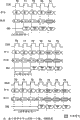
The READ train of impulses is from read command (by CS#, WE#, RAS#, CAS# regulation) starting, as shown in Figure 6.The row and the group address of beginning provide from read command.During the READ train of impulses, be available after the stand-by period at the CAS behind the read command from the correct data sensing element of begin column address.Each data sensing element subsequently was correct before next rising edge clock.After finishing train of impulses, suppose not have other orders to be started, DQ will enter the High-Z state.The train of impulses of full page will continue, till termination.(in the ending of this page, it arrives row 0 with hidden, and proceeds.) can block with later read command from the data of any READ train of impulses, and can be followed from the data of later REAB order from the data of regular length READ train of impulses with being right after.Under any situation, continuous data stream can be held.First data cell of the train of impulses of making a fresh start is followed the last back, unit at the train of impulses of finishing, or follows in the intercepted last data cell back of wanting of long train of impulses.New read command should be to be issued in the x cycle before the correct clock edge in the last data cell of wanting, and wherein x equals the CAS stand-by period and subtracts 1.This is shown among Fig. 7 the CAS stand-by period for 1,2 and 3; Data cell n+3 or 4 train of impulses last, or the wanting at last of long train of impulses.Synchronous flash memory uses pipeline organization, so, do not need the 2n rule relevant with the structure of looking ahead.Any clock period of read command after can read command formerly started.Can carry out the read access at random of the full speed in one page, as shown in Figure 8, maybe can carry out each READ subsequently different groups.
Can be blocked (before the WRITE order WRITE SETUP must be arranged) with later WRITE order from the data of any READ train of impulses, and from the data of regular length READ train of impulses can be right after followed by data from subsequently WRITE order (being subjected to bus commutation restriction).WRITE can be started in the clock edge that is right after from last (or wanting at last) data cell back of READ train of impulses, as long as the I/O competition can be avoided.In given system design, can property: the device that drives the input data enters Low-Z (low-resistance) before synchronous flash memory DQ enters High-Z.In this case, the time-delay of single at least cycle will appear between last read data and the WRITE order.
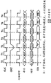
The DQM input is used for avoiding the I/O competition, as shown in Figure 9.The DQM signal must adhere at least before WRITE order that (HIGH) two clocks (for output buffer, the DQM stand-by period is two clocks) adhere to (HIGH), so that suppress the data output from READ.In case the WRITE order is registered, DQ will enter High-Z (or remaining on High-Z), and no matter the state of DQM signal.The DQM signal must be removed before WRITE order adheres to, (for input buffer, the DQM stand-by period is zero) is so that guarantee the not conductively-closed of data that writes.Fig. 9 represents that clock frequency wherein allows to add the NOP cycle and the situation of avoiding bus contention.
Regular length or full page READ train of impulses can block with ACTIVE TERMINATE order (can be or not necessarily organize specific) or BURST TERMINATE (not being that group is specific) order.ACTIVE TERMINATE or BURST TERMINATE order should be to be issued in the x cycle before the correct clock edge in the last data cell of wanting, and wherein x equals the CAS stand-by period and subtracts 1.This is represented for each possible CAS stand-by period on Figure 10; The last data cell of wanting of data cell n+3 or four train of impulses, or the data cell of wanting at last of long train of impulses.
Single position WRITE is from WRITE order (by CS#, WE#, RAS#, CAS# regulation) starting, as shown in figure 11.The row of beginning and group address provide from the WRITE order.In case the WRITE order is registered, just can as truth table 4 and 5 regulations, carry out read command.Example of expression on Figure 12.During WRITE, correct data input as one man is registered with the WRITE order.
Unlike SDRAM, the row that synchronous flash memory does not need PRECHARGE to order deactivation to be opened in specific group, or the row of in all groups, opening.The ACTIVETERMINATE order is similar to BURST TERMINATE order; Yet ACTIVE TERMINATE can be or not necessarily organize specific.Adhering to importing A10 during ACTIVE TERMINATE order is HIGH, with the BURST READ that terminates in any group.As A10 when being low during ACTIVETERMINATE order, BA0 and BA1 will determine which group will accept terminates operation.ACTIVE TERMINATE is not for being that group by A10, BA0, BA1 addressing is considered to NOP.
When not being when conducting interviews, if clock allows, CKE and NOP or COMMANDINHIBIT (when not conducting interviews) as one man are registered as LOW, then emergent power reduction.After internal state machine operation (comprise WRITE operation) was finished, ingoing power reduces made deactivation input and output impact damper (not comprising CKE), so that save power when holding state.
Power reduces state can be withdrawed from by registering NOP or COMMAND INHIBIT and CKE HIGH in the clock edge of wanting (satisfying tCKS).Reduce operation for exemplary power, consult Figure 13.
The clock suspending mode appears when column access/train of impulses is carrying out being registered as LOW with CKE.Under the clock suspending mode, internal clocking is by deactivation, " freezing " synchronous logic.So as to being sampled as each rising edge clock of LOW, next clock internal rising edge is ended for CKE.Any order or the data that appear at the input pin place in the time at suspended internal clocking edge are left in the basket, the any data that appear at DQ pin place are driven maintenance, and burst counter do not add increment, as long as clock is ended (seeing the example of Figure 14).The clock suspending mode can withdraw from by registration CKE HIGH; Internal clocking and relevant operation will be afterwards rising edge clock the time proceed.
In one embodiment, train of impulses read/single WriteMode is a default mode.All WRITE orders cause the visit of single column position (length is one train of impulses), and read command conducts interviews to row according to the burst length and the sequence of programming.The storage operation of CKE signal is used in following truth table 3 expressions.
Truth table 3-CKE
| CKE n-1 | CKE n | Current state | COMMAND n(order) | ACTION n(action) |
| L | L | Power reduces clock to be ended | X X | Keep power to reduce and keep clock to end |
| L | H | Power reduces clock to be ended | Order is forbidden or NOP X | Withdraw from the power reduction and withdraw from the clock termination |
| H | L | All group free time read or write | The order forbid or NOP correct | The ingoing power reduction enters clock and ends |
| H | H | See truth table 4 |
Truth table 4-current state group n-is to the order of group n
| Current state | CS# | RAS# | CAS# | WE# | Order/action |
| Any | H L | X H | X H | X H | COMMAND INHIBIT (NOP/ continues previous operation) NO OPERATION (NOP/ continues previous operation) |
| Idle | L L L L | L L L L | H L L H | H H L L | ACTIVE (selecting and activate delegation) LOAD COMMAND REGISTER (load command register) LOAD MODE REGISTER (loading pattern register) ACTIVE TERMINATE (work termination) |
| Row work | L L L L | H L L | L L H L | H L L H | READ (selecting row and beginning READ train of impulses) WRITE (selecting row and beginning WRITE) ACTIVE TERMINATE LOAD COMMAND REGISTER |
| Read | L L L L L | H H L H L | L L H H L | H L L L H | READ (select row and begin new READ train of impulses) WRITE (selecting row and beginning WRITE) ACTIVE TERMINATE BURST TERMINATE LOAD COMMAND REGISTER |
| Write | L L | H L | L L | H H | READ (select row and begin new READ train of impulses) LOAD COMMAND REGISTER |
Truth table 5-current state group n-is to the order of group m
| Current state | CS# | RAS# | CAS# | WE# | Order/action |
| Any | H L | X H | X H | X H | COMMAND INHIBIT (NOP/ continues previous operation) NO OPERATION (NOP/ continues previous operation) |
| Idle | X | X | X | X | Any order, otherwise allow group m |
| Line activating, work, or the work termination | L L L L L | L H H L L | H L L H L | H H L L H | ACTIVE (selecting and activate row) READ (selecting row and beginning READ train of impulses) WRITE (selecting row and beginning WRITE) ACTIVE TERMINATE LOAD COMMAND REGISTER |
| Read | L L L L L | L H H L L | H L L H L | H H L L H | ACTIVE (selecting and activate row) READ (select row and begin new READ train of impulses) WRITE (selecting row and beginning WRITE) ACTIVE TERMINATE LOAD COMMAND REGISTER |
| Write | L L L L L | L H L H L | H L H H L | H H L L H | ACTIVE (selecting and activate row) READ (selecting row and beginning READ train of impulses) ACTIVE TERMINATE BURST TERMINATE LOAD COMMAND REGISTER |
Function declaration
Synchronous flash memory is quoted a plurality of characteristics, so that it is ideally suited for the code storage on the SDRAM bus and carries out suitable application.Memory array is segmented into each erase block.Each piece can be wiped free of, and does not influence the data in the piece that is stored in other.These memory blocks are read out, write and wipe by command execution logic 130 (CEL) is given an order.The operation of CEL control internal state machine 132 (ISM), it controls all ERASENVMODE REGISTER (wiping the NV mode register), WRITE NVMODE REGISTER (writing the NV mode register), WRITE (writing), BLOCK ERASE (piece is wiped), BLOCK PROTECT (block protection), DEVICE PROTECT (device protection), UNPROTECT ALL BLOCK (pieces that non-protection is all) and VERIFY (checking) operation fully.Each storage unit of ISM 132 protection are not subjected to too wiping, and make each storage unit optimization, so that maximum data keeps.In addition, ISM be reduced in the system widely or externally in the programmable device for the necessary control of write device.
Synchronous flash memory is organized as 16 independently erasable memory blocks, and they allow to wipe the part of storer and do not influence remaining memory data.Any piece can be a hardware protection, avoids disadvantageous and wipes or write.Piece requirement RP# pin before being corrected of protection is driven to VHH (quite high voltage).The piece of the 256K word at 0 and 15 places can have additional hardware protection in the position.In case carried out PROTECT BLOCK (protection piece) order for these pieces, UNPROTECT ALL BLOCKS order is just unclamped except all pieces the piece at position 0 and 15 places, unless the RP# pin is to be in VHH.This in system during the firmware update code for key added security is provided, if the words of undesired power disturbance or system reset.
The sequential of power-on initialization, ERASE, WRITE and PROTECT can come programmed algorithms all in the control store array to be simplified by using ISM.ISM guarantees that protection is not too wiped, and makes each unit write the surplus optimization.In WRITE operating period, ISM adds increment automatically and monitors the WRITE attempt, and checking is write surplus and upgraded the ISM status register on each storage unit.When BLOCK ERASE operation was performed, ISM automatically crossed the piece (eliminate and too wipe) of writing whole addressing, added increment and monitored the ERASE attempt, and be arranged on the bit in the ISM status register.
8 bit ISM status registers 134 allow ppus 200 to monitor the state of ISM in WRITE, ERASE and PROTECT operating period.A bit of 8 bit status registers (SR7) is provided with and removes by ISM fully.This bit represents whether ISM is busy with ERASE, WRITE or PROTECT task.Additional error message (SR3, SR4 and SR5) in three other bits is set up: writes and protects the piece mistake, wipe the piece mistake all with non-protection, and device protection mistake.Status register bit SR0, SR1 and SR2 provide ISM to operate ongoing details.But whether user's surveillance device level or group level ISM operation (comprising which group is in ISM control down) well afoot.These six bits (SR3-SR5) must be removed by main system.Below with reference to table 2 status register is described in more detail.
In order to allow peak power to preserve, synchronous flash memory is characterised in that low-down electric current, dark power reduces pattern.In order to enter this pattern, RP# pin one 40 (resetting/the power reduction) is taken as VSS ± 0.2V.For the RESET that prevents to be harmful to, RP# must remain Vss in 100ns before device enters reset mode.Remain on Vss for RP#, device will enter degree of depth power and reduce pattern.After device enters degree of depth power reduction pattern, the transfer on RP# from LOW to HIGH, will cause as here the general introduction, device power-on initialization sequence.After entering reset mode but before entering the degree of depth power reduction pattern transfer of RP# from LOW to HIGH need be before sending executable order the time-delay of 1 μ s.When device enters into degree of depth power and reduces pattern, do not comprise that all impact dampers of RP# impact damper are under an embargo, and current draw is low, for example, the maximal value of 50 μ A under 3.3V VCC.During degree of depth power reduced, the input that is added to RP# must remain on Vss.Enter into RESET (resetting) pattern, remove status register 134, and ISM 132 is set to the array reading mode.
The synchronous flash memory array structure is designed to allow the sector to be wiped free of, and leaves the remainder of array alone.Array is divided into 16 addressable " piece ", and they can be wiped independently.By erase block, rather than whole array, total device permanance is enhanced, as system flexibility.It is block-oriented having only ERASE and BLOCK PROTECT function.16 addressable equally is divided into four groups 104,106,108 and 110, and each organizes four pieces.Four groups have simultaneously reads-writes function.Can carry out simultaneously with READ operation for any group ISM WRITE or ERASE operation any other group.Can carry out poll to status register 134, be in the ISM operation to determine which group.Synchronous flash memory has single fundamental operation ISM, and power controlling is connected initialization, ERASE, WRITE and PROTECT operation.Carry out an ISM operation at any time only; Yet some other order comprises the READ operation, can be performed when carrying out the ISM operation.Operational order by ISM control is defined as operation of group level or device level operation.WRITE and ERASE are group level ISM operation.After ISM group operation is by starting, may exports incorrect data to the READ of any position of group, and will read array the READ of any other group.READ STATUS REGISTER order is with the content of output state register 134.The ISM status bits will represent when the ISM operation finishes (SR7=1).When the ISM operation is finished, group will enter the array reading mode automatically.ERASE NVMODEREGISTER, WRITE NVMODE REGISTER, BLOCK PROTECT, DEVICE PROTECT and UNPROTECT ALL BLOCK are the ISM operations of device level.In case the operation of ISM device level is started, to the content of any group READ with output array.READ STATUS REGISTER (read states register) order can be issued, to determine finishing of ISM operation.When SR7=1, the ISM operation will be finished and later ISM operation can be started.Can protect with hardware circuit for any, not be subjected to the influence of undesired ERASE or WRITE, it requires the RP# pin to be driven to VHH before WRITE or ERASE begin, as explained later.
Any can be by hardware protection, so that the Additional Protection of responsive part for firmware to be provided.During the piece of WRITE or ERASE hardware protection, the RP# pin must remain on the VHH, till WRITE or ERASE finish.Under the situation that is not RP#=VHH, will be prevented from for any WRITE of piece or the ERASE attempt of protection, and will cause writing or erasure error.The piece at 0 and 15 places can have additional hardware protection in the position, to stop disadvantageous WRITE or ERASE operation.In the present embodiment, these pieces cannot be unclamped by software by UNPROTECT ALL BLOCK order, unless RP#=VHH.Any guard mode can be verified by the block protection bit of reading it with READSTATUS REGISTER order.In addition, in order to protect a piece, must send three cycle command sequences with block address.
Synchronous flash memory is characterised in that to have three kinds of dissimilar READ.Depend on pattern, the READ operation will produce data from one of memory array, status register or cell configuration register.Must be after the cycle to the READ of cell configuration register or status register at LCR-ACTIVE, and the burst length of output data will be stipulated by the mode register value of setting.Later READ or do not attend school out array at the READ of LCR-ACTIVE after the cycle.Yet, have several difference, and will in following joint, be described.
Content to any group read command output storage array.When carrying out WRITE or ERASE ISM operation, the READ to any position in the group under ISM control may export incorrect data.After withdrawing from the RESET operation, device will enter into the array reading mode automatically.
The READ that status register 134 is carried out requires and input sequence identical when reading array, except LCR READ STATUS REGISTER (70H) cycle must be before the ACTIVE READ cycle.The burst length of status register data output is by mode register 148 regulations.Status register contents is updated and latchs at the next rising edge clock through the CAS stand-by period.Device will enter into the array reading mode automatically, be used for later READ.
The READ that any cell configuration register 136 is carried out requires and input sequence identical when the read states register, except must sending specific address.WE# must be HIGH (high level), and DQM and CS# must be LOW (low levels).In order to read the compatible ID of manufacturer, the address must be at 000000H, and for read-out device ID, the address must be at 000001H.The three-address (xx0002H) of any block protection bit in each erase block located to be read out, and device protection bit is read out from position 000003H.
The DQ pin is used for importing data or is used for input array.Address pins be used for the specified address position or during the LOAD COMMAND REGISTER cycle to the CEL input command.The order input is issued to CEL to 8 bits command, so that the mode of operation of control device.WRITE is used for memory array input data.Following joint is described this two kinds of input types.
For fill order input, DQM must be LOW, and CS# and WE# must be LOW.Address pins or DQ pin are used for input command.The address pins that is not used in input command is " need not manage it ", and must remain stable.8 bits command are transfused at DQ0-DQ7 or A0-A7 place, and are latched at the rising edge clock place.
The bit that the WRITE of memory array is wanted is set to logical zero, but can not change to logical one to given bit from logical zero.Any bit is set to logical one and need wipes whole.In order to carry out WRITE, DQM must be LOW, and CS# and WE# must be LOW, and VCCP must remain on VCC.Writing of piece to protection also requires the RP# pin to remain on VHH.A0-A11 provides the address that will be written into, and the data that will be written to array are transfused at DQ pin place.Data and address are latched at the rising edge of clock.Must there be the WRITESETUP order front of WRITE.
In order to simplify the write store piece, synchronous flash memory is quoted ISM, and it is in WRITE and all internal algorithm of ERASE cycle inner control.8 bits command groups are used for control device.For the inventory of correct order, can consult truth table 1 and 2.
8 bit ISM status registers 134 (seeing Table 2) are polled, with finishing or any relevant mistake of check ERASE NVMODEREGISTER, WRITE NVMODE REGISTER, WRITE, ERASE, BLOCK PROTECT, DEVICE PROTECT or UNPROTECT ALL BLOCK.Finishing of ISM operation can be monitored by sending READ STATUS REGISTER (70H) order.The content of status register is output to DQ0-DQ7, and by the mode register value of setting regulation, locate to be updated at next rising edge clock (through the CAS stand-by period) in the fixed pulse string length.The ISM operation will be finished when SR7=1.The bit of all regulations is provided with by ISM, but only the ISM status bits is resetted by ISM.Wipe/unprotected, the piece that writes/protect, the device protection must be removed by using CLEAR STATUS REGISTER (50H) order.This allows user when to select poll and removes status register.For example, main system can be carried out a plurality of WRITE operations before the test status register, rather than checked later at each independent WRITE.Adhere to the RP# signal or the reduction of device power also will be removed status register.
Table 2 status register
| Status bits | The status register bit | Explanation |
| SR7 | It is busy that |
When carrying out WRITE or BLOCK ERASE, the state of the work of ISM bit show state machine.This bit of steering logic poll, with determine when wipe with the write state bit be correct. |
| SR6 | Keep | Keep for using in the future. |
| SR5 | Wipe/piece of 0=success that the |
ES is set to 1 after carrying out (but not having good authentication) in the ERASE cycle of maximum number by ISM.If BLOCK UNPROTECT operation is unsuccessful, then this bit also is set to 1.ES only removes by CLEAR STATUS REGISTER order or by RESET (resetting). |
| SR4 | The |
WS is set to 1 after carrying out (but not having good authentication) in the WRITE cycle of maximum number by ISM.If BLOCK or DEVICE PROTECT operation are unsuccessful, then this bit also is set to 1.WS only removes by CLEAR STATUS REGISTER order or by RESET (resetting). |
| SR2 SR1 | Group A1 ISM state group A0 ISM state | When SR0=0, the group under ISM control can be from BA0, BA1:[0,0] |
| SR3 | The |
If attempt to carry out incorrect WRITE, ERASE, PROTECT BLOCK, PROTECT DEVICE or UNPROTECT ALL BLOCKS, then DPS is set to 1.After one of these orders were issued, RP#, the condition of block protection bit and device protection bit compared, with the operation that determines whether to allow to want.Must remove by CLEAR STATUS REGISTER order or by RESET. |
| SR0 | Device/ |
If the ISM operation is the device level operation, then DPS is set to 1.Correct READ for any group of array can be right after the ISM WRITE operation back of following in device level.When DBS was set to 0, the ISM operation was the operation of group level.READ to group under ISM control may cause incorrect data.SR2 and SR3 can be decoded, are under ISM control to determine which group. |
Device ID, the compatible ID of manufacturer, device guard mode and block protection state all can be read out by sending READ DEVICE CONFIGURATION (90H) order.For the register of reading to want, must adhere to specific address.For the more details of various cell configuration registers 136, can consult table 3.
Table 3 cell configuration
| Cell configuration | The address | Data | Condition |
| Manufacturer's compatibility | 000000H | 2CH | Read manufacturer's compatibility |
| Device ID | 000001H | D3H | Read-out device ID |
| The block protection bit | xx0002H xx0002H | DQ0=1 DQ0=0 | Protected of piece comes protected |
| Device protection bit | 000003H 000003H | DQ0=1 DQ0=0 | Prevention is carried out the block protection correction and is allowed to carry out the block protection correction |
Can give an order, so that device enters different operator schemes.Each pattern has specific operation, and these operations can be performed under this pattern.Several modes requires a series of orders to be written into before they arrive.Following joint is described the character of each pattern, and truth table 1 and 2 is listed the needed all command sequences of the operation of wanting for execution.Read-write function and allow to write or wipe, and read any other group simultaneously for any group of execution fundamental operation.For write operation, the LCR-ACTIVE-WRITE command sequence in truth table 2 must be finished in the clock period in succession.Yet,, in command sequence, can send the NOP or the COMMAND INHIBIT of hard-core number in order to simplify the synchronous flash controller function.For supplementary protection, in three cycles, these command sequences must have identical group address.If group address changes during the LCR-ACTIVE-WRITE command sequence, if or command sequence be not continue (except NOP and COMMAND INHIBIT, they are permitted), write with erase status bit (SR4 and SR5) and will be set up, and operation is under an embargo.
After the power-on and device is being sent before any work order, synchronous flash memory is initialised.After to be added to VCC, VCCQ and VCCP (side by side) and clock be stable, RP# transferred to HIGH from LOW at power.After RP# transfers to HIGH, need a time-delay (in one embodiment, the time-delay of 100 μ s), so that finish the internal components initialization, device is in the array reading mode when finishing the device initialization, and executable order can be issued to device.
For read-out device ID, the compatible ID of manufacturer, device protection bit and each block protection bit, send READ DEVICE CONFIGURATION (90H) order.Under this pattern, specific address is issued the information of wanting of reading.The compatible ID of manufacturer is read out at the 000000H place; Device ID is read out at the 000001H place.Compatible ID of manufacturer and device ID export at the DQ0-DQ7 place.Device protection bit is read out at the 000003H place; And the three-address position (xx0002H) of each block protection bit in each piece located to be read out.Device and block protection bit are exported at the DQ0 place.
Need come in three orders in succession of in succession clock edge data are input to array (NOP and COMMAND INHIBIT permission were between the cycle).In the period 1, utilize at the WRITE at A0-A7 place SETUP (40H) and provide LOAD COMMAND REGISTER order, and group address is issued on BA0, BA1.Next Command is ACTIVE, and it activates row address and confirms group address.Period 3 is WRITE, during this period row, group address and the data of issue beginning.The ISM status bits (is passed through the CAS stand-by period) at the clock edge of following and is located to be set up.When ISM carries out WRITE, ISM status bits (SR7) will be 0.READ operation to group under ISM control may produce incorrect data.When ISM status bits (SR7) when being set to logical one, WRITE is done, and group will be in the array reading mode, and is ready to executable order.Be written to the piece of hardware protection, also require the RP# pin to be set to VHH before, and RP# must remain on VHH, till ISM WRITE operation is finished in the period 3 (WRITE).If the LCR-ACTIVE-WRITE command sequence is not finished or group address changes in any of three cycles in the cycle in succession, then write with erase status bit (SR4 and SR5) to be set up.Behind ISM starting WRITE, it can not be interrupted, except reducing these parts by RESET or by power.During WRITE, do like this, may upset the data that are written into.
Carry out the ERASE sequence all bits in the piece are set to logical one.For carrying out the command sequence that the necessary command sequence of ERASE is similar to WRITE.For the added security of wiping for accidental piece is provided, need come the ERASE of motion block in three orders in succession of in succession clock edge.In the period 1, the ERASE SETUP (20H) at A0-A7 place is distributed to LOAD COMMAND REGISTER, and the group address of the piece that will be wiped free of is issued on the BA1 at BA0.Next Command is ACTIVE, A10 wherein, and A11, BA0, BA1 provide the address of the piece that will be wiped free of.Period 3 is WRITE, provides ERASECONFIRM (DOH) during this period at the DQ0-DQ7 place, and issues group address again.The ISM status bits (is passed through the CAS stand-by period) at the clock edge of following and is located to be set up.After ERASE CONFIRM (DOH) is published, ISM will begin the ERASE of the piece of institute's addressing.Any READ operation for the group of the piece that wherein has institute's addressing may be exported incorrect data.When the ERASE operation was finished, this group was in the array reading mode, and is ready to executable order.Wipe by the piece of hardware protection, also require the RP# pin to be set to VHH before, and RP# must remain on VHH, till ERASE finishes (SR7=1) in the period 3 (WRITE).If the LCR-ACTIVE-WRITE command sequence is not finished (NOP and COMMAND INHIBIT permission were between the cycle) in the cycle in succession or group address changes in one or more command cycles, then write with erase status bit (SR4 and SR5) and will be set up, and operation is under an embargo.
The content of mode register 148 can be copied in the NV mode register 147 with WRITE NVMODE REGISTER order.Before being written to the NV mode register, ERASE NVMODEREGISTER command sequence must be done, so that all bits are set to logical one in the NV mode register.In order to carry out the command sequence that ERASE NVMODE REGISTER and the necessary command sequence of WRITE NVMODEREGISTER are similar to WRITE.Can consult truth table 2 for the more information of finishing the necessary LCR-ACTIVE-WRITE order of ERASENVMODE REGISTER and WRITE NVMODE REGISTER.After the WRITE cycle of ERASE NVMODEREGISTER or WRITE NVMODE REGISTER command sequence was registered, read command can be issued to array.Current ISM operation be done and SR7=1 before, will not allow new WRITE operation.
Carry out BLOCK PROTECT sequence, allow to carry out the software/hardware protection of the first order for given piece.Storer comprises 16 bit register, and it has a bit corresponding to 16 pieces that can protect.Storer also has register, is used for protecting entire device not to be subjected to writing device bit with erase operation to provide.In order to carry out the order that the necessary command sequence of BLOCK PROTECT is similar to WRITE.For the added security for accidental block protection is provided, need three command cycles in succession to start BLOCK PROTECT.In the period 1, the PROTECT SETUP (60H) at A0-A7 place order is distributed to LOAD COMMAND REGISTER, and wants protected group address on BA0, BA1, to be issued.Next Command is ACTIVE, the row of its starting in the piece that will protect, and confirm group address.Period 3 is WRITE, during this period at DQ0-DQ7 place issue BLOCK PROTECT CONFIRM (01H), and issues group address again.The ISM status bits (is passed through the CAS stand-by period) at the clock edge of following and is located to be set up.ISM will begin the protection operation.If LCR-ACTIVE-WRITE does not finish (NOP and COMMAND INHIBIT permission were between the cycle) in the cycle in succession or group address changes, then write with erase status bit (SR4 and SR5) and will be set up, and operation is under an embargo.When ISM status bits (SR7) when being set to logical one, PROTECT finishes, and this group will be in the array reading mode, and is ready to executable order.In case the block protection bit is set to 1 (protection), it can only be reset to 0, if UNPROTECT ALL BLOCKS order.UNPROTECT ALL BLOCKS command sequence is similar to BLOCK PROTECT order; Yet,, utilize UNPROTECT ALL BLOCKS COMFIRM (DOH) order to send WRITE, and the address is " need not manage it " in the period 3.For additional information, consult truth table 2.The piece at 0 and 15 places has added security in the position.In case the block protection bit at 0 and 15 places is set to 1 (protection) in the position, each bit just can only be reset to 0, if RP# was added to VHH before the period 3 of UNPROTECT operation, and remains on VHH, till (SR7=1) finished in operation.In addition, if device protection bit is set up, then RP# must be added to VHH before the period 3, and remained on VHH, till BLOCK PROTECT or UNPROTECT ALL BLOCKS operation are finished.For the guard mode of proof mass, can send READ DEVICE CONFIGURATION (90H) order.
Carry out DEVICE PROTECT sequence, be changed to 1 the device protection ratio is ad hoc, and stoping block protection bit correction.In order to carry out the order that the necessary command sequence of DEVICE PROTECT is similar to WRITE.Need three command cycles in succession to start DEVICE PROTECT sequence.In the period 1, the PROTECT SETUP (60H) at A0-A7 place order is distributed to LOADCOMMAND REGISTER, and group address is issued on BA0, BA1.Group address is " need not manage it ", but identical group address must be used in three all cycles.Next Command is ACTIVE.Period 3 is WRITE, and during this period at DQ0-DQ7 place issue DEVICEPROTECT (F1H), and RP# is added to VHH.The ISM status bits (is passed through the CAS stand-by period) at the clock edge of following and is located to be set up.Executable order can be distributed to device.RP# must remain on VHH, till WRITE finishes (SR7=1).Before current I SM operation is finished, new WRITE operation will do not allowed.In case device protection bit is set up, it just can not be reset to 0.Be set to 1 for device protection bit, BLOCK PROTECT or BLOCKUNPROTECT are prevented from, unless RP# is in VHH in any operating period.Device protection bit does not influence WRITE or ERASE operation.For the more information of piece and device protection operation, can consult table 4.
Table 4 protection operation truth table

After ISM status bits (SR7) was set up, device/group (SR0), device protection (SR3), group A0 (SR1), group A1 (SR2), write/protect piece (SR4) and wipe/non-protection (SR5) status bits can be verified.If one of SR3, SR4, SR5 status bits or combination are set up, mistake then appears during operation.ISM can not reset SR3, SR4 or SR5 bit.In order to remove these bits, must provide CLEAR STATUS REGISTER (50H) order.Table 5 is listed wrong combination.
The decoding of table 5 status register mistake

Synchronous flash memory is designed with manufactured, satisfies advanced code and call data storage.In order to ensure this reliability level, VCCP must remain Vcc during WRITE or ERASE.Operation beyond these restrictions can reduce can be to the WRITE and the number in ERASE cycle of device execution.Each piece is for 100, and the minimum value of the permanance in 000WRITE/ERASE cycle is designed with processed.
Synchronous flash memory provides several power saving features that can be utilized to save power under the array reading mode.Degree of depth power reduces pattern and can be allowed to by RP# is added to VSS ± 0.2V.Current draw under this pattern (ICC) is low, such as the maximal value of 50 μ A.When CS# is HIGH, device will enter the work standby mode.Under this pattern, electric current also is low, such as the maximum ICC electric current of 30mA.If writing, wiping or protecting operating period CS# to be added to HIGH, then ISM will continue the WRITE operation, and the Iccp power of device consumption work, till operation is finished.
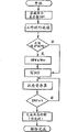
With reference to Figure 16, expression is according to the process flow diagram of the self-timing writing sequence of one embodiment of the present of invention on the figure.Sequence comprises load command register (code 40H), accepts the order and the row address of work and accepts write order and column address.Whether then, sequence provides the status register poll, finish to determine to write.Whether this poll monitor status register bit 7 (SR7) is set to 1 to determine it.Can comprise optional thermodynamic state verification.When writing when finishing, array is placed in the array reading mode.
With reference to Figure 17, provide the process flow diagram of writing state-checking sequence completely on the figure according to one embodiment of the present of invention.This sequence is checked status register bit 4 (SR4), whether is set to 0 to determine it.If it is SR4 is 1, then wrong in write operation.Sequence is also checked status register bit 3 (SR3), whether is set to 0 to determine it.If SR3 is 1, incorrect write error is arranged during write operation then.
With reference to Figure 18, provide the process flow diagram of wiping sequence according to the self-timing piece of one embodiment of the present of invention on the figure.This sequence comprises load command register (code 20H), and order and the row address of accepting work.Storer determines then whether piece is protected.If it is not protected, then storer is carried out write operation (D0H) to this piece, and for finishing situation monitored state register.Can carry out optional thermodynamic state verification, and storer is placed in the array reading mode.If block is protected, and does not then allow to wipe, unless the RP# signal is in the voltage (VHH) that has improved.
Figure 19 represents the process flow diagram according to the erase status-checking sequence of piece completely of one embodiment of the present of invention.This sequence monitored state register is to determine whether to occur command sequence error (SR4 or SR5=1).If SR3 is set to 1, incorrect wiping or unprotected mistake then appears.At last, if SR5 is changed to 1, take place then that piece is wiped or non-protection mistake.
Figure 20 is the process flow diagram according to the block protection sequence of one embodiment of the present of invention.This sequence comprises load command register (code 60H), and order and the row address of accepting work.Storer determines then whether piece is protected.If it is not protected, then storer is carried out write operation (01H) to this piece, and for finishing situation monitored state register.Can carry out optional thermodynamic state verification, and storer is placed in the array reading mode.If block is protected, and does not then allow to wipe, unless the RP# signal is in the voltage (VHH) that has improved.
Consult Figure 21, the process flow diagram according to the bulk state-checking sequence completely of one embodiment of the present of invention is provided on the figure.This sequence monitored state register bit 3,4 and 5 is to determine whether to detect mistake.
Figure 22 is the process flow diagram according to the device protection sequence of one embodiment of the present of invention.This sequence comprises load command register (code 60H), and order and the row address of accepting work.Storer determines then whether RP# is in VHH.Storer is carried out write operation (F1H), and for finishing situation monitored state register.Can carry out optional thermodynamic state verification, and storer is placed in the array reading mode.
Figure 23 is the process flow diagram according to the non-protection sequence of the piece of one embodiment of the present of invention.This sequence comprises load command register (code 60H), and order and the row address of accepting work.Storer determines then whether this memory device is protected.If it is not protected, then storer determines whether guide position (piece 0 and 15) is protected.If the neither one piece is protected, then storer is carried out write operation (D0H) to this piece, and for finishing situation monitored state register.Can carry out optional thermodynamic state verification, and storer is placed in the array reading mode.If device is protected, then do not allow to wipe, unless the RP# signal is in the voltage (VHH) that has improved.Similarly, if guide position is protected, then storer determines whether that all pieces should not protect.
Figure 24 shows the sequential of initialization and the operation of loading pattern register.Mode register is programmed by accepting the loading pattern register command and accept operation code (operational code) on address wire.Operation sign indicating number is packed in this mode register.As mentioned above, after power-on, the content of non-volatile mode register automatically is loaded into mode register, and not necessarily needs the mode register operation.
Figure 25 represents the sequential of clock suspending mode operation, and Figure 26 represents the sequential of another train of impulses read operation.Figure 27 represents that alternately group reads the sequential of visit.Here, need the order of work to change group address.Expression full page train of impulses read operation on Figure 28.Should be pointed out that complete page or leaf train of impulses is not to terminate certainly, and need the order of termination.
Figure 29 is by using the sequential of data mask signal indication read operation.The DQM signal is used for shadow data output, like this, does not provide Dout m+1 in the DQ connection.
With reference to Figure 30, the sequential of expression write operation on the figure, reading different groups followed in the back.In this operation, a carries out write operation to group, and group b is carried out reading subsequently.The same row of visit in each group.
With reference to Figure 31, the sequential of expression write operation on the figure, follow same group read the back.In this operation, a carries out write operation to group, and group a is carried out reading subsequently.For the different row of read operation visit, and storer must wait for that previous write operation is done.This is different with the read operation of Figure 30, and wherein read operation is not delayed time owing to write operation.
Synchronous flash memory provides the write operation that does not have the stand-by period.These are different with SDRAM, and SDRAM requirement system provides the stand-by period for write operation, just as read operation.So write operation is not taken the as many cycle with the SDRAM cost away from system bus.Therefore, can the improvement system read throughput, see Figure 12, the data Din that wherein writes is being provided on the same clock period with write order and column address.The clock period T1 of Figure 12 needs not be nop command (seeing Figure 30).Read command can be provided on the next clock period of following in the write data back.Therefore, remain availablely though read operation needs DQ to be connected in clock period of the predetermined number after the read command (stand-by period), DQ connects to be right after and is provided back (not having the stand-by period) at write order and is used.Like this, the present invention allows zero bus commutation capacity.This is to be different from SDRAM widely, needs a large amount of waits in SDRAM when replacing between the read and write operation on system bus.Synchronous flash memory provides this two characteristics, and can improve the bus throughput.
With reference to Figure 32, system 32 of the present invention comprises synchronous memories 302, and it has the inner latch 304 of writing, and is used for being stored in the write data of accepting on the DQ input end 306.Write latch and be coupled to memory array 310.In addition, memory array can be arranged to a plurality of addressable.Data can be written to a piece, and can carry out read operation to other piece simultaneously.The storage unit of array can be a non-volatile memory cells.Data communication connection 306 is used in the two-way communication with external unit (such as processor 320 or other Memory Controllers).
Data buffer 330 can be coupled to data communication and connect, so that the management bidirectional data communication.This impact damper can be the traditional FIFO or the input/output (i/o) buffer circuit of streamline.Write latch and be coupling between impact damper and the memory array, so that be latched in the data that data communication connects to be provided.At last, control circuit is provided to manage the read and write operation of carrying out on array.
By latching the input write data, data bus 306 (DQ) can be released and carry out write operation by the use latched data.When carrying out first write operation, subsequently, can be under an embargo to the write operation of storer.Yet, can obtain bus, so that on storer, carry out read operation at once.The present invention should not obscure with traditional input/output (i/o) buffer structure.Just, though the existing memory device uses input buffer and the output buffer on the DQ outgoing route on DQ input path, the clock latency that is used for the read and write operation is retained as identical.The present invention can comprise that the input/output (i/o) buffer circuit provides the interface with DQ path and ppu.Additional write latch allow storer isolate to a zone of storer write path/operation, and allow the data reading operation on other memory areas simultaneously.
Existing flash memory device has functipnal capability very limited the time.Just, existing flash memory typically when carrying out write operation, hinders reading from storer.Some storage component part is by ending ongoing write operation, allow the reading of array then, and reads when allowing to write.The remainder of other flash memory storer by providing limited sector, these sectors to be written into can be for reading use, and read when allowing to write.The purpose of such flash memory is for the needs of the EEPROM that separates in the elimination system.Be provided at the EEPROM unit in the flash memory between limited sector null, and the remainder that stays storer is used for the quickflashing operation.
The invention provides the flash array of the group structure that is arranged to be similar to SDRAM.In one embodiment, the synchronous flash memory of 64M is divided into four groups, and they have the addressing identical with 64MSDRAM.These groups further are divided into littler addressable sector, and they can be wiped free of or be programmed.Read and write when storer allows based on group.Therefore, a group can be written into, and reads simultaneously and can carry out any other group simultaneously.
As well known by persons skilled in the art, SDRAM can open a public row in each group.Read and write operation can and stride across on the group of array going of opening and sequentially carry out.
This synchronous flash memory has the group structure that is similar to SDRAM, allows to open delegation in each group when a group is written into.With reference to Figure 33, an embodiment of expression disposal system 400 of the present invention on the figure.Synchronous flash memory 410 is coupled to a plurality of processors 440,442,444 and 446 by BDB Bi-directional Data Bus 435.Storer comprises and is aligned to a plurality of groups 412,414,416 and 418 array of non-volatile memory cells.Read/write circuit 430 usually is shown so that the data communication of management and array.When operation, processor such as processor 440, can start the write operation for the row 420 of array group 412.When carrying out write operation, second processor, such as processor 442, can be from the row 420 of second array group sense data.This allows four processors to work independently on synchronous flash memory.The present invention is not limited to four groups or four processors.Single or multiple processors can be carried out write operation for a group, and simultaneously from remaining memory array bank sense data, for example see Figure 32.Therefore, can carry out the read operation of write operation and a plurality of whiles simultaneously.
As mentioned above, synchronous flash memory of the present invention can the specific read operation of execution group, and simultaneously another group is carried out write operation.When first and second ppus were attempted the storer read and write, a problem appearred.Just, if processor is attempted same memory block executable operations, then these two processors need be known, which operation storer are carried out, to avoid competition.In existing systems, operation when bus host is used for following the tracks of and is carried out by a plurality of processors.In order to reduce the expense of bus host, can provide two options.
An option is to comprise automatic read states pattern in storer, the content of its output state register when attempting storer execution second operation.Just, when storer is carried out write operation, the content of any read operation meeting output state register of on storer, carrying out.This option is interrupted read operation by the output state data, even attempt different array blocks is carried out read operation.Second option is the state of writing that requirement processor sense status register is determined storer.Utilize this option to interrupt read operation once more.
The present invention can provide two state readout modes, the interference when avoiding in for different array group read operation.First state model that provides in this synchronous flash memory provides the state of whole storage component part.Just, status register represents whether memory array or non-array register are carried out write operation.This state model is called as the memory state pattern here, by from the request of ppu and selectively activated.In response to the memory state order, the control circuit of storer provides the status register data on DQ connects.
Second state model is the specific pattern of memory array bank.Under this pattern, status data automatically is provided in the DQ connection.Just, if processor starts write operation for array group, then this group is placed in the group state model.When write operation was performed, any attempt later, that read from this group caused output state register data in the DQ connection.Therefore, memorizer control circuit allows multicomputer system not work together intrusively mutually.
Storer comprises group register 450 (Figure 33), and which array group it can be provided to discern is written into.When operation, storer is programmed to the group register, and use group register is as pointer.During read operation, read access and group register are compared, and if at this group address place ongoing write operation is arranged, the automatic output state register data of storer then.So the present invention can reduce the expense of bus host, therefore, can allow better multiprocessor ability.
Individual pulse string state
As mentioned above, existing flash memory comprises the single status read operation.In these storeies, in case storer enters WriteMode, any attempt of reading from storer all provides the content of status register.This allows the user to monitor how write operation is carrying out.
The present invention has the state reading mode, and it is exported from mode register data with the state read command.And synchronous flash memory can be programmed by using the load command register manipulation, to set up burst length and clock latency.These values of setting mainly are used for controlling the sequential of output data during read operation.Existing flash memory problem therebetween is, the register data of output is got ready for controlled burst length and the output of stand-by period.
This storer can be placed in the register read pattern, and in a series of clock period (train of impulses) the output register data.The length of train of impulses is by programming to mode register and predesignated, as above explanation.For example, mode register can be set to have the burst length of 4 words and 3 clock latency.After receiving the status register read command, because clock latency, this storer is the output state content of registers after 3 clock period, and because the burst length value of setting goes up continuation output state content of registers in bus (DQ connection) in 4 cycles.Register read is not limited to the status register reading, also can be applicable to read-out device identification register, manufacturer's identification register or is used for any a plurality of work registers of storage operation data.
Obscuring when in storage component part, carrying out reading in the write operation by using burst length and the clock latency value of setting to come the control register data to export to reduce.For example, if the user need know the state of operating in storage component part, then can start the read states order, and the status register data are output in the overall pulse string length.
Conclusion
Synchronous flash memory comprises array of non-volatile memory cells.Memory array is aligned to row and column, and can further be arranged in addressable.Data communication connect be used for external unit (such as, processor or other Memory Controllers) carry out bidirectional data communication.Storer can be in the data of exporting on data communication connects during a series of clock period from storage register, so that the train of impulses of register data to be provided.Storer can also clock latency value according to the rules provide register data.Register data can comprise status data, operation setting Value Data, make identification and storage component part identification.
Claims (19)
1. method of operating the synchronous memories device comprises:
In mode register, determine the read pulse string length in x cycle, so that the data of exporting were output with x clock period in succession from the status register of synchronous memories device;
The starting register read is so that read the data that are stored in the status register; And
In x clock period in succession, on connecting, external data exports the data that are stored in the status register,
Described method also comprises the clock latency of determining y cycle, so that y the clock period of data after the starting register read that is stored in the status register is output.
2. the process of claim 1 wherein that the status register data comprise the data of non-array, service data for example, is made identification or storage component part identification at status data.
3. method of operating the synchronous memories device comprises:
Receive the read states register command; And
In x clock period, export status register data in response to this read register order from the synchronous memories device,
Wherein y the clock period of status register data after receiving this read register order is output.
4. the method for claim 3, wherein the synchronous memories device is the synchronous flash memory device with non-volatile memory cells.
5. the method for claim 3, wherein the status register data comprise the data of non-array, for example service data, status data, manufacturing identification or storage component part identification.
6. the method for claim 3, wherein x clock period selected from 2,4,8 or 16 clock period.
7. method that reads out in the register data in the synchronous memories device comprises:
The status register read command of from processor is provided to storage component part;
On the input end of first clock period, receive this register read order at storage component part;
Read the status register data that are stored in the memory register;
Connecting these status register data of output in the data communication of synchronous memories device during two after described first clock period or clock cycle more for a long time, wherein the output of these status register data clock latency interval of a storage of after receiving the register read order, having been delayed time.
8. the method for claim 7, wherein the status register data comprise the data of non-array, for example service data, status data, manufacturing identification or storage component part identification.
9. the method for claim 7 also comprises:
The burst length of synchronous memories device is set, so that determine a plurality of clock period that these status register data are output; And
Clock latency is set at interval.
10. the method for claim 9, wherein burst length was selected from 2,4,8 or 16 clock period.
11. the method for claim 7, wherein the synchronous memories device is the synchronous flash memory device with non-volatile memory cells.
12. a method of operating the synchronous memories device comprises:
Array to storage component part is carried out write operation;
During carrying out write operation, a status register read command of from processor is provided to storage component part;
On the input end of first clock period, receive this status register read command at storage component part;
Read the status register data that are stored in the memory register;
Connecting these status register data of output in the data communication of synchronous memories device during two after described first clock period or clock cycle more for a long time, wherein the output of these status register data clock latency interval of a storage of after receiving this status register read command, having been delayed time.
13. the method for claim 12, the wherein state of writing of this status register data representation storage component part.
14. the method for claim 12 also comprises:
The burst length of synchronous memories device is set, so that determine a plurality of clock period that these status register data are output; And
Clock latency is set at interval.
15. a synchronous memories device comprises:
Memory cell array;
Control circuit;
The clock signal input that is input to this control circuit connects; And
Be connected the status data register between this memory cell array and the control circuit;
Wherein this control circuit provides data from this status data register in response to the external register read command on the DOL Data Output Line of the storage component part that is connected to this memory cell array, and this control circuit is being programmed these data of output in the clock period of number according to the read pulse string length value of programming.
16. the synchronous memories device of claim 15, wherein storage unit is non-volatile.
17. the synchronous memories device of claim 15, wherein control circuit provides data on output connects behind the clock latency interval of the storage after the read register order.
18. a disposal system comprises:
Processor; And
Be coupled to the non-volatile synchronous memories device of processor, it comprises,
Memory cell array,
Control circuit;
The clock signal input that is input to this control circuit connects; And
Be connected the status data register between this memory cell array and the control circuit;
Wherein this control circuit provides data from this status data register in response to the external register read command on the DOL Data Output Line of the storage component part that is connected to this memory cell array, and this control circuit is being programmed these data of output in the clock period of number according to the read pulse string length value of programming.
19. the disposal system of claim 18, wherein control circuit provides data on output line behind the clock latency interval of the storage after the described external register read command.
Applications Claiming Priority (2)
| Application Number | Priority Date | Filing Date | Title |
|---|---|---|---|
| US09/626,190 US6728798B1 (en) | 2000-07-28 | 2000-07-28 | Synchronous flash memory with status burst output |
| US09/626,190 | 2000-07-28 |
Related Child Applications (1)
| Application Number | Title | Priority Date | Filing Date |
|---|---|---|---|
| CN2009102217820A Division CN101930794A (en) | 2000-07-28 | 2001-07-27 | Synchronous flash memory with status burst output |
Publications (2)
| Publication Number | Publication Date |
|---|---|
| CN1466762A CN1466762A (en) | 2004-01-07 |
| CN100578659C true CN100578659C (en) | 2010-01-06 |
Family
ID=24509337
Family Applications (2)
| Application Number | Title | Priority Date | Filing Date |
|---|---|---|---|
| CN2009102217820A Pending CN101930794A (en) | 2000-07-28 | 2001-07-27 | Synchronous flash memory with status burst output |
| CN01816420A Expired - Fee Related CN100578659C (en) | 2000-07-28 | 2001-07-27 | Synchronous flash memory with status burst output |
Family Applications Before (1)
| Application Number | Title | Priority Date | Filing Date |
|---|---|---|---|
| CN2009102217820A Pending CN101930794A (en) | 2000-07-28 | 2001-07-27 | Synchronous flash memory with status burst output |
Country Status (9)
| Country | Link |
|---|---|
| US (4) | US6728798B1 (en) |
| EP (1) | EP1305804B1 (en) |
| JP (1) | JP3809909B2 (en) |
| KR (1) | KR100511820B1 (en) |
| CN (2) | CN101930794A (en) |
| AT (1) | ATE492880T1 (en) |
| AU (1) | AU2001277210A1 (en) |
| DE (2) | DE60143700D1 (en) |
| WO (1) | WO2002011148A1 (en) |
Families Citing this family (52)
| Publication number | Priority date | Publication date | Assignee | Title |
|---|---|---|---|---|
| US6728798B1 (en) * | 2000-07-28 | 2004-04-27 | Micron Technology, Inc. | Synchronous flash memory with status burst output |
| US20030204675A1 (en) * | 2002-04-29 | 2003-10-30 | Dover Lance W. | Method and system to retrieve information from a storage device |
| JP4010400B2 (en) * | 2002-06-14 | 2007-11-21 | シャープ株式会社 | Semiconductor memory device and data write control method |
| US7149824B2 (en) | 2002-07-10 | 2006-12-12 | Micron Technology, Inc. | Dynamically setting burst length of memory device by applying signal to at least one external pin during a read or write transaction |
| US7254690B2 (en) * | 2003-06-02 | 2007-08-07 | S. Aqua Semiconductor Llc | Pipelined semiconductor memories and systems |
| US8122187B2 (en) * | 2004-07-02 | 2012-02-21 | Qualcomm Incorporated | Refreshing dynamic volatile memory |
| CN100530146C (en) * | 2004-08-26 | 2009-08-19 | 鸿富锦精密工业(深圳)有限公司 | BIOS on-line rewriting method |
| US20060143330A1 (en) * | 2004-12-23 | 2006-06-29 | Oliver Kiehl | Method for data transmit burst length control |
| US7640392B2 (en) | 2005-06-23 | 2009-12-29 | Qualcomm Incorporated | Non-DRAM indicator and method of accessing data not stored in DRAM array |
| US7620783B2 (en) * | 2005-02-14 | 2009-11-17 | Qualcomm Incorporated | Method and apparatus for obtaining memory status information cross-reference to related applications |
| US7230876B2 (en) * | 2005-02-14 | 2007-06-12 | Qualcomm Incorporated | Register read for volatile memory |
| KR100762259B1 (en) | 2005-09-12 | 2007-10-01 | 삼성전자주식회사 | Nand flash memory device with burst read latency function |
| US9262326B2 (en) * | 2006-08-14 | 2016-02-16 | Qualcomm Incorporated | Method and apparatus to enable the cooperative signaling of a shared bus interrupt in a multi-rank memory subsystem |
| US7904639B2 (en) * | 2006-08-22 | 2011-03-08 | Mosaid Technologies Incorporated | Modular command structure for memory and memory system |
| US7593279B2 (en) * | 2006-10-11 | 2009-09-22 | Qualcomm Incorporated | Concurrent status register read |
| KR101364443B1 (en) * | 2007-01-31 | 2014-02-17 | 삼성전자주식회사 | Memory system, memory controller and memory for the same, and method of constructing signal of the same |
| US8086785B2 (en) | 2007-02-22 | 2011-12-27 | Mosaid Technologies Incorporated | System and method of page buffer operation for memory devices |
| US8046527B2 (en) | 2007-02-22 | 2011-10-25 | Mosaid Technologies Incorporated | Apparatus and method for using a page buffer of a memory device as a temporary cache |
| KR100813631B1 (en) * | 2007-03-19 | 2008-03-14 | 삼성전자주식회사 | Flash memory device capable of improving read performance |
| WO2009050806A1 (en) * | 2007-10-18 | 2009-04-23 | Fujitsu Limited | Memory device, method for data transmission, and transmission control circuit |
| US9354890B1 (en) | 2007-10-23 | 2016-05-31 | Marvell International Ltd. | Call stack structure for enabling execution of code outside of a subroutine and between call stack frames |
| KR20100106410A (en) | 2007-12-21 | 2010-10-01 | 모사이드 테크놀로지스 인코퍼레이티드 | Non-volatile semiconductor memory device with power saving feature |
| US8291248B2 (en) * | 2007-12-21 | 2012-10-16 | Mosaid Technologies Incorporated | Non-volatile semiconductor memory device with power saving feature |
| US9442758B1 (en) | 2008-01-21 | 2016-09-13 | Marvell International Ltd. | Dynamic processor core switching |
| KR100955684B1 (en) * | 2008-10-02 | 2010-05-06 | 주식회사 하이닉스반도체 | Flag signal gneration circuit and semiconductor memory device |
| US8762621B2 (en) * | 2008-10-28 | 2014-06-24 | Micron Technology, Inc. | Logical unit operation |
| US20110258362A1 (en) * | 2008-12-19 | 2011-10-20 | Mclaren Moray | Redundant data storage for uniform read latency |
| US20100287217A1 (en) * | 2009-04-08 | 2010-11-11 | Google Inc. | Host control of background garbage collection in a data storage device |
| US9582443B1 (en) | 2010-02-12 | 2017-02-28 | Marvell International Ltd. | Serial control channel processor for executing time-based instructions |
| US8582382B2 (en) * | 2010-03-23 | 2013-11-12 | Mosaid Technologies Incorporated | Memory system having a plurality of serially connected devices |
| US8843692B2 (en) | 2010-04-27 | 2014-09-23 | Conversant Intellectual Property Management Inc. | System of interconnected nonvolatile memories having automatic status packet |
| KR101817159B1 (en) * | 2011-02-17 | 2018-02-22 | 삼성전자 주식회사 | Semiconductor package having TSV interposer and method of manufacturing the same |
| KR20120098325A (en) * | 2011-02-28 | 2012-09-05 | 에스케이하이닉스 주식회사 | Non-volatile memory system and setting method of feature |
| JP2012203919A (en) | 2011-03-23 | 2012-10-22 | Toshiba Corp | Semiconductor memory device and control method therefor |
| US9098694B1 (en) * | 2011-07-06 | 2015-08-04 | Marvell International Ltd. | Clone-resistant logic |
| US9471484B2 (en) | 2012-09-19 | 2016-10-18 | Novachips Canada Inc. | Flash memory controller having dual mode pin-out |
| US9741442B2 (en) * | 2013-03-12 | 2017-08-22 | Sandisk Technologies Llc | System and method of reading data from memory concurrently with sending write data to the memory |
| US9430411B2 (en) * | 2013-11-13 | 2016-08-30 | Sandisk Technologies Llc | Method and system for communicating with non-volatile memory |
| KR102164019B1 (en) * | 2014-01-27 | 2020-10-12 | 에스케이하이닉스 주식회사 | Burst Length control device and semiconductor device including the same |
| US9257165B2 (en) * | 2014-03-10 | 2016-02-09 | Everspin Technologies, Inc. | Assisted local source line |
| KR20150112075A (en) * | 2014-03-26 | 2015-10-07 | 삼성전자주식회사 | Storage device and operating method of storage device |
| JP6420139B2 (en) * | 2014-12-26 | 2018-11-07 | シナプティクス・ジャパン合同会社 | Semiconductor device |
| US10063376B2 (en) | 2015-10-01 | 2018-08-28 | International Business Machines Corporation | Access control and security for synchronous input/output links |
| US10120818B2 (en) | 2015-10-01 | 2018-11-06 | International Business Machines Corporation | Synchronous input/output command |
| US11776591B2 (en) * | 2019-09-26 | 2023-10-03 | Arm Limited | Concurrent access techniques utilizing wordlines with the same row address in single port memory |
| US11386937B2 (en) | 2019-10-12 | 2022-07-12 | Arm Limited | System device and method for providing single port memory access in bitcell array by tracking dummy wordline |
| CN110955387B (en) * | 2019-10-25 | 2023-10-24 | 合肥沛睿微电子股份有限公司 | Method for adaptively identifying flash memory type and computer readable storage medium and device |
| TWI780653B (en) * | 2019-11-08 | 2022-10-11 | 大陸商合肥沛睿微電子股份有限公司 | Method for identifying flash memory type and device thereof |
| TWI780654B (en) * | 2019-11-08 | 2022-10-11 | 大陸商合肥沛睿微電子股份有限公司 | Apparatus for adaptive identifying flash memory type and method thereof |
| US11720281B2 (en) * | 2020-12-11 | 2023-08-08 | Micron Technology, Inc. | Status information retrieval for a memory device |
| WO2023009122A1 (en) * | 2021-07-29 | 2023-02-02 | Hewlett-Packard Development Company, L.P. | Minimize delay times for status checks to flash memory |
| FR3138709A1 (en) * | 2022-08-04 | 2024-02-09 | STMicroelectronics (Alps) SAS | FLASH memory device |
Family Cites Families (30)
| Publication number | Priority date | Publication date | Assignee | Title |
|---|---|---|---|---|
| KR940006094B1 (en) | 1989-08-17 | 1994-07-06 | 삼성전자 주식회사 | Nonvolatile semiconductor memory device and fabricating method thereof |
| JP3319105B2 (en) | 1993-12-15 | 2002-08-26 | 富士通株式会社 | Synchronous memory |
| KR970001699B1 (en) * | 1994-03-03 | 1997-02-13 | 삼성전자 주식회사 | Syncronous semiconductor memory device having the function of automatic precharge |
| US5696917A (en) | 1994-06-03 | 1997-12-09 | Intel Corporation | Method and apparatus for performing burst read operations in an asynchronous nonvolatile memory |
| USRE36532E (en) * | 1995-03-02 | 2000-01-25 | Samsung Electronics Co., Ltd. | Synchronous semiconductor memory device having an auto-precharge function |
| US5570381A (en) * | 1995-04-28 | 1996-10-29 | Mosaid Technologies Incorporated | Synchronous DRAM tester |
| US5661054A (en) | 1995-05-19 | 1997-08-26 | Micron Technology, Inc. | Method of forming a non-volatile memory array |
| US5600605A (en) | 1995-06-07 | 1997-02-04 | Micron Technology, Inc. | Auto-activate on synchronous dynamic random access memory |
| US5666321A (en) | 1995-09-01 | 1997-09-09 | Micron Technology, Inc. | Synchronous DRAM memory with asynchronous column decode |
| JP2874619B2 (en) | 1995-11-29 | 1999-03-24 | 日本電気株式会社 | Semiconductor storage device |
| US5749086A (en) | 1996-02-29 | 1998-05-05 | Micron Technology, Inc. | Simplified clocked DRAM with a fast command input |
| EP0929075B1 (en) * | 1996-09-26 | 2003-08-20 | Mitsubishi Denki Kabushiki Kaisha | Synchronous type semiconductor memory device |
| US5787457A (en) | 1996-10-18 | 1998-07-28 | International Business Machines Corporation | Cached synchronous DRAM architecture allowing concurrent DRAM operations |
| US5974514A (en) | 1996-11-12 | 1999-10-26 | Hewlett-Packard | Controlling SDRAM memory by using truncated burst read-modify-write memory operations |
| JP4057084B2 (en) | 1996-12-26 | 2008-03-05 | 株式会社ルネサステクノロジ | Semiconductor memory device |
| US5825710A (en) | 1997-02-26 | 1998-10-20 | Powerchip Semiconductor Corp. | Synchronous semiconductor memory device |
| KR100248353B1 (en) | 1997-04-09 | 2000-03-15 | 김영환 | Semiconductor memory device |
| US5892777A (en) | 1997-05-05 | 1999-04-06 | Motorola, Inc. | Apparatus and method for observing the mode of a memory device |
| US5903496A (en) | 1997-06-25 | 1999-05-11 | Intel Corporation | Synchronous page-mode non-volatile memory with burst order circuitry |
| JP3161384B2 (en) * | 1997-09-16 | 2001-04-25 | 日本電気株式会社 | Semiconductor memory device and access method therefor |
| US6141247A (en) | 1997-10-24 | 2000-10-31 | Micron Technology, Inc. | Non-volatile data storage unit and method of controlling same |
| KR100274602B1 (en) * | 1997-11-20 | 2000-12-15 | 윤종용 | Synchronous memory device |
| US5917724A (en) * | 1997-12-20 | 1999-06-29 | Ncr Corporation | Method for predicting disk drive failure by monitoring the rate of growth of defects within a disk drive |
| JPH11203864A (en) | 1998-01-14 | 1999-07-30 | Mitsubishi Electric Corp | Synchronous type semiconductor storage device |
| KR100306965B1 (en) * | 1998-08-07 | 2001-11-30 | 윤종용 | Data Transmission Circuit of Synchronous Semiconductor Memory Device |
| FI990038A (en) * | 1999-01-11 | 2000-07-12 | Nokia Mobile Phones Ltd | Procedure for refreshing a dynamic memory |
| US6785764B1 (en) * | 2000-05-11 | 2004-08-31 | Micron Technology, Inc. | Synchronous flash memory with non-volatile mode register |
| US6728798B1 (en) * | 2000-07-28 | 2004-04-27 | Micron Technology, Inc. | Synchronous flash memory with status burst output |
| US6580659B1 (en) * | 2000-08-25 | 2003-06-17 | Micron Technology, Inc. | Burst read addressing in a non-volatile memory device |
| US6480429B2 (en) * | 2001-02-12 | 2002-11-12 | Micron Technology, Inc. | Shared redundancy for memory having column addressing |
-
2000
- 2000-07-28 US US09/626,190 patent/US6728798B1/en not_active Expired - Fee Related
-
2001
- 2001-07-27 AT AT01955000T patent/ATE492880T1/en not_active IP Right Cessation
- 2001-07-27 DE DE60143700T patent/DE60143700D1/de not_active Expired - Lifetime
- 2001-07-27 AU AU2001277210A patent/AU2001277210A1/en not_active Abandoned
- 2001-07-27 JP JP2002516785A patent/JP3809909B2/en not_active Expired - Fee Related
- 2001-07-27 WO PCT/US2001/023695 patent/WO2002011148A1/en active IP Right Grant
- 2001-07-27 KR KR10-2003-7001296A patent/KR100511820B1/en not_active IP Right Cessation
- 2001-07-27 CN CN2009102217820A patent/CN101930794A/en active Pending
- 2001-07-27 EP EP01955000A patent/EP1305804B1/en not_active Expired - Lifetime
- 2001-07-27 CN CN01816420A patent/CN100578659C/en not_active Expired - Fee Related
- 2001-07-27 DE DE1305804T patent/DE1305804T1/en active Pending
-
2004
- 2004-04-26 US US10/831,823 patent/US7096283B2/en not_active Expired - Fee Related
-
2005
- 2005-08-31 US US11/216,953 patent/US7603534B2/en not_active Expired - Fee Related
-
2009
- 2009-09-30 US US12/570,570 patent/US8010767B2/en not_active Expired - Fee Related
Also Published As
| Publication number | Publication date |
|---|---|
| JP2004505404A (en) | 2004-02-19 |
| KR100511820B1 (en) | 2005-09-05 |
| KR20030028556A (en) | 2003-04-08 |
| US20040199713A1 (en) | 2004-10-07 |
| CN1466762A (en) | 2004-01-07 |
| DE1305804T1 (en) | 2003-11-27 |
| EP1305804B1 (en) | 2010-12-22 |
| US7603534B2 (en) | 2009-10-13 |
| AU2001277210A1 (en) | 2002-02-13 |
| WO2002011148A1 (en) | 2002-02-07 |
| US20050289313A1 (en) | 2005-12-29 |
| ATE492880T1 (en) | 2011-01-15 |
| US7096283B2 (en) | 2006-08-22 |
| CN101930794A (en) | 2010-12-29 |
| DE60143700D1 (en) | 2011-02-03 |
| US8010767B2 (en) | 2011-08-30 |
| EP1305804A1 (en) | 2003-05-02 |
| JP3809909B2 (en) | 2006-08-16 |
| US20100088484A1 (en) | 2010-04-08 |
| US6728798B1 (en) | 2004-04-27 |
Similar Documents
| Publication | Publication Date | Title |
|---|---|---|
| CN100578659C (en) | Synchronous flash memory with status burst output | |
| US6615307B1 (en) | Flash with consistent latency for read operations | |
| KR100438635B1 (en) | Elimination of precharge operation in synchronous flash memory | |
| US6442076B1 (en) | Flash memory with multiple status reading capability | |
| US6580659B1 (en) | Burst read addressing in a non-volatile memory device | |
| US6459617B1 (en) | Method and circuitry for bank tracking in write command sequence | |
| US7278004B2 (en) | Burst write in a non-volatile memory device | |
| US6851026B1 (en) | Synchronous flash memory with concurrent write and read operation | |
| US6728161B1 (en) | Zero latency-zero bus turnaround synchronous flash memory | |
| US20040057320A1 (en) | Top/bottom symmetrical protection scheme for flash | |
| JP3631209B2 (en) | Flash with consistent latency in read processing | |
| KR100508041B1 (en) | Interface command architecture for synchronous flash memory | |
| KR100438634B1 (en) | Synchronous flash memory with concurrent write and read operation | |
| KR100495848B1 (en) | Zero-latency-zero bus turnaround synchronous flash memory | |
| JP2003529878A (en) | Synchronous flash memory having nonvolatile mode register |
Legal Events
| Date | Code | Title | Description |
|---|---|---|---|
| C06 | Publication | ||
| PB01 | Publication | ||
| C10 | Entry into substantive examination | ||
| SE01 | Entry into force of request for substantive examination | ||
| C14 | Grant of patent or utility model | ||
| GR01 | Patent grant | ||
| C17 | Cessation of patent right | ||
| CF01 | Termination of patent right due to non-payment of annual fee |
Granted publication date: 20100106 Termination date: 20100727 |