CN100538428C - Zoom-lens system - Google Patents
Zoom-lens system Download PDFInfo
- Publication number
- CN100538428C CN100538428C CNB2004100832038A CN200410083203A CN100538428C CN 100538428 C CN100538428 C CN 100538428C CN B2004100832038 A CNB2004100832038 A CN B2004100832038A CN 200410083203 A CN200410083203 A CN 200410083203A CN 100538428 C CN100538428 C CN 100538428C
- Authority
- CN
- China
- Prior art keywords
- lens
- zoom
- combination
- lens combination
- group
- Prior art date
- Legal status (The legal status is an assumption and is not a legal conclusion. Google has not performed a legal analysis and makes no representation as to the accuracy of the status listed.)
- Expired - Fee Related
Links
Images


Classifications
-
- G—PHYSICS
- G02—OPTICS
- G02B—OPTICAL ELEMENTS, SYSTEMS OR APPARATUS
- G02B15/00—Optical objectives with means for varying the magnification
- G02B15/14—Optical objectives with means for varying the magnification by axial movement of one or more lenses or groups of lenses relative to the image plane for continuously varying the equivalent focal length of the objective
- G02B15/143—Optical objectives with means for varying the magnification by axial movement of one or more lenses or groups of lenses relative to the image plane for continuously varying the equivalent focal length of the objective having three groups only
- G02B15/1431—Optical objectives with means for varying the magnification by axial movement of one or more lenses or groups of lenses relative to the image plane for continuously varying the equivalent focal length of the objective having three groups only the first group being positive
- G02B15/143105—Optical objectives with means for varying the magnification by axial movement of one or more lenses or groups of lenses relative to the image plane for continuously varying the equivalent focal length of the objective having three groups only the first group being positive arranged +-+
Abstract
The invention provides that a kind of this system comprises first group with positive refractive power, has second group of negative refractive power by using diffraction optical element to have the zoom-lens system of high optical property, and have the 3rd group of positive refractive power.When from wide-angle side state zoom when dolly-out,ing dolly-back the end state, the distance between the distance between first group and second group and second group and the 3rd group changes.The 3rd group of back group of comprising target one side that is located at largest interval in the 3rd group, have preceding group of positive refractive power and being located at image one side at interval, having negative refractive power.Preceding group comprises aperture diaphragm and diffraction optics face.The incident angle that incides the chief ray that reaches maximum picture height on the diffraction optics face is 10 degree or littler.And, satisfy given condition.
Description
Invention field
The present invention relates to have the film camera of being suitable for, the zoom-lens system of the diffraction optical element of image camera and digital still life camera.
Background of invention
Along with development of technology, various types of zoom-lens systems have been proposed.As a kind of film camera that is used for, image camera, especially for the optical system of digital still life camera, three group zoom lens systems, be called the type zoom-lens system of dolly-out,ing dolly-back again, have from target side establish with very short back focal length in order just-structure of negative-positive refractive power.For this class example, be disclosed in No. the 11-305126, the Japanese Patent Application Publication.
Yet in the progress that obtains aspect the imaging technique, for example miniaturization of image device pixel pitch is difficult to not only realize high optical property (particularly gamut) but also realize compactedness with simple mechanism according to recently.
Summary of the invention
The present invention makes in view of aforesaid problem, and its objective is provides a kind of zoom-lens system by using diffraction optical element to have good optical property and compactedness.
According to an aspect of the present invention, a kind of zoom-lens system comprises from target and establishing in order: first lens combination with positive refractive power; Second lens combination with negative refractive power; With the 3rd lens combination with positive refractive power; When the location status of lens combination is become when dolly-out,ing dolly-back the end state by the wide-angle side state, the distance between described first lens combination and described second lens combination changes; And the distance between described second lens combination and described the 3rd lens combination changes; Described the 3rd lens combination is made of front lens group with positive refractive power and the rear lens group with negative refractive power, front lens group is located at target one side of maximum airspace in the 3rd lens combination, and rear lens group is located at image one side of maximum airspace in the 3rd lens combination; Described front lens group comprises aperture diaphragm and diffraction optics face; Inciding the incident angle that described diffraction optics face reaches the chief ray of maximum picture height is 10 degree or littler; And satisfy the following conditions expression formula:
0.3<R/fw<5.0 (1)
Wherein R represents to be located at the radius-of-curvature of its target side of positive lens of image one side of described aperture diaphragm, and fw represents to be in the focal length of the zoom-lens system of wide-angle side state.
In a kind of preferred implementation of the present invention, described front lens group has the diffraction optics face on the lens surface that is positioned at ingress of air, and satisfies the following conditions expression formula:
0.05<L/f3<1.0 (2)
Wherein L represents to have the thickness (when described surface was positioned on the cemented lens, this thickness was bond thickness) of the lens element of described diffraction optics face, and f3 represents the focal length of described the 3rd lens combination.
In a kind of preferred implementation of the present invention, satisfy the following conditions expression formula:
0.1<C/fw<3.0 (3)
Wherein C represents the effective diameter of described diffraction optics face, and fw represents to be in the focal length of the described zoom-lens system of wide-angle side state.
In a kind of preferred implementation of the present invention, in described the 3rd lens combination, described front lens group has cemented lens, and the diffraction optics face is formed on the image side of this bonding positive lens, and satisfies the following conditions expression formula:
0.001<P/fw<0.05 (4)
Wherein P represents the minigroove pitch of described diffraction optics face, and fw represents to be in the focal length of the described zoom-lens system of wide-angle side state.
In a kind of preferred implementation of the present invention, described first lens combination has cemented lens; Described second lens combination has the bonding positive lens that is located at target one side position, and this cemented lens is made by the bonding biconcave lens of positive meniscus lens; And described the 3rd lens combination has front lens group and rear lens group, and front lens group comprises biconvex lens, bonding positive lens and the positive meniscus lens of establishing in order from target of being just accord with; Rear lens group comprises diverging meniscus lens and the biconcave lens of establishing in order from target.
In a kind of preferred implementation of the present invention, carry out damping by moving described second lens combination, and satisfy the following conditions expression formula along the direction that is basically perpendicular to optical axis:
ΔS/fw<0.1 (5)
Wherein Δ S represents that the maximum offset that moves in described second lens combination, fw represent to be in the focal length of the described zoom-lens system of wide-angle side state when damping.
From below in conjunction with accompanying drawing to detailed description of the preferred embodiment, other feature and advantage of the present invention can easily be understood.
Description of drawings
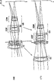
Fig. 1 is the synoptic diagram that its lens arrangement of zoom-lens system of example 1 of the present invention is shown;
Fig. 2 illustrates when the location status of lens combination to become when dolly-out,ing dolly-back end state (T) synoptic diagram of the zoom track of its each lens combination of zoom-lens system of example 1 from wide-angle side state (W);
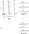
Fig. 3 figures out the various aberrations of zoom-lens system under wide-angle side state (W) of example 1;
Fig. 4 figures out the various aberrations of zoom-lens system under the end state (T) of dolly-out,ing dolly-back of example 1;
Fig. 5 is the synoptic diagram that its lens arrangement of zoom-lens system of example 2 of the present invention is shown;
Fig. 6 illustrates when the location status of lens combination to become when dolly-out,ing dolly-back end state (T) synoptic diagram of the zoom track of its each lens combination of zoom-lens system of example 2 from wide-angle side state (W);
Fig. 7 figures out the various aberrations of zoom-lens system under wide-angle side state (W) of example 2;
Fig. 8 figures out the various aberrations of zoom-lens system under the end state (T) of dolly-out,ing dolly-back of example 2;
Fig. 9 is the synoptic diagram that its lens arrangement of zoom-lens system of example 3 of the present invention is shown;
Figure 10 illustrates when the location status of lens combination to become when dolly-out,ing dolly-back end state (T) synoptic diagram of the zoom track of its each lens combination of zoom-lens system of example 3 from wide-angle side state (W);
Figure 11 figures out the various aberrations of zoom-lens system under wide-angle side state (W) of example 3;
Figure 12 figures out the various aberrations of zoom-lens system under the end state (T) of dolly-out,ing dolly-back of example 3;
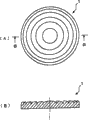
Figure 13 A and 13B are the synoptic diagram that the example of Fresnel-zone plate is shown, and wherein Figure 13 A is a planimetric map, and Figure 13 B is the sectional view along B-B face intercepting among Figure 13 A.
Embodiment
Below referring to appended description of drawings preferred implementation of the present invention.
The feature of many group zoom lens of general description system.Because the structure zoom-lens system needs at least two lens combination, suppose that therefore many group zoom lens system has three lens combination or the lens arrangement of poly-lens group more.
In many group zoom lens system, realize high zoom ratio by the number that increases the lens combination of being responsible for zoom.Owing to be easy to burden (burdens) equalization, therefore can obtain splendid optical property with each lens combination aberration correction.Yet, when the number of the lens combination that moves along optical axis increases, the mechanism of the lens barrel more complicated that can become, thus be easy to increase manufacturing cost.In many group zoom lens according to the present invention system, use a kind of three group zoom lens systems, this system comprises first lens combination with positive refractive power of establishing in order from target side, has second lens combination of negative refractive power, and the 3rd lens combination with positive refractive power.Therefore, suppressing by simplifying the internal structure of an organization under the situation of manufacturing cost, can when guaranteeing the zoom ratio of appropriate amount, obtain splendid optical property.In many group zoom lens according to the present invention system, owing to can on the basis of vibration weakening, obtain optical property preferably, so it also is suitable for electronic imaging device.
Next diffraction optics face and diffraction optical element are described.Usually, known the method for three kinds of offset light, as refraction, reflection and diffraction.Diffraction surfaces is the optical surface that demonstrates diffraction.Diffraction optical element is the optical element with diffraction optics face, as known traditionally Fresnel-zone plate or diffraction grating.Known that this class diffraction optical element can demonstrate the performance that is different from refraction or reflection.Especially, it has negative dispersion.This performance is especially effective for correcting chromatic aberration, can realize the splendid correction to aberration, and this is (promptly can not with common glass realization) that need not expensive Extra-low Dispersion glass be had never been realized.The character of relevant diffraction optical element can obtain more detailed content by " the diffraction optical element brief introduction " of Japanese optics association management, and this association is the branch offices of Japanese applied physics association, (optoelectronics, 1997).
In many group zoom lens according to the present invention system, diffraction optical element is located in the front lens group with positive refractive power, this front lens group is arranged in target one side of the 3rd lens combination maximum empty headroom, thereby obtains splendid optical property by means of its effect., generate the diffraction optics face herein, perhaps realize producing the surface of diffraction, for example Fresnel zone plate by offset light by on the surface of the optical element of making by glass or resin material, forming diffraction grating.Incidentally, Figure 13 A and 13B are the synoptic diagram that the example of Fresnel-zone plate is shown, and wherein Figure 13 A is a planimetric map, and Figure 13 B is the sectional view along B-B face intercepting among Figure 13 A.Although the Fresnel-zone plate 1 that is illustrated among Figure 13 is kinoform (Kinoform) type, its pitch is a continuous curve, forms the grating groove of diffraction optical element, and this periodic structure also can be stepwise shape, perhaps diagonal angle shape.
In many group zoom lens according to the present invention system, identical with the ordinary optical system with diffraction optical element, the incident angle that preferably incides diffraction optical element is as far as possible little.This is that the place is easy to produce passage of scintillation light at the diffraction optics face, thereby can worsen optical property because when the incident angle of light becomes big.For the better optical property that the passage of scintillation light that obtains not produced by diffraction optical element influences too much, for optical system of the present invention, preferably incident angle is 10 degree or littler.As long as although diffraction optical element can be arranged on any position of satisfying this condition, in zoom-lens system according to the present invention, preferably diffraction optical element is arranged in the front lens group of the 3rd lens combination.In order to obtain this effect fully, preferably incident angle is 7 degree or littler.The incident angle that further preferably is under the end state of dolly-out,ing dolly-back is 5 degree or littler, and the incident angle that is under the wide-angle side state is 6 degree or littler.
Referring to conditional expression (1) to (5) table focus lens of the present invention system is described below.Zoom-lens system according to the present invention satisfies following conditions expression formula (1):
0.3<R/fw<5.0 (1)
Wherein R represents the radius-of-curvature of positive lens target side, and this positive lens is located at image one side of aperture diaphragm S in the 3rd lens combination, and fw represents to be in the focal length of the zoom-lens system under the wide-angle side state.
Conditional expression (1) has been determined the radius of curvature R of positive lens target side, and this positive lens is located at image one side of aperture diaphragm in the 3rd lens combination.Front lens group is placed near the aperture diaphragm S often.The shape of the lens of formation front lens group and correcting spherical aberration and intelligent image difference have very big relation.Especially, the positive lens that is located at aperture diaphragm (being arranged in the 3rd lens combination) image one side is very important for keeping aberration balancing preferably.It is desirable to the convex surface head for target of positive lens.Therefore, for balance aberration preferably, the OK range of the radius of curvature R of positive lens target side is recently determined by the focal length that is in the zoom-lens system under the wide-angle side state.Herein, R〉0.
When the ratio of R/fw equals or is higher than going up in limited time of conditional expression (1), the value of radius of curvature R becomes excessive, and spherical aberration also becomes excessive along forward, thereby can not obtain optical property preferably.On the other hand, it is too small that radius of curvature R becomes in limited time when the ratio of R/fw is equal to or less than conditional expression (1) following, and spherical aberration becomes excessive along negative sense, thereby can not obtain optical property preferably.In order to obtain effect of the present invention fully, be limited to 2.0 on the preferred settings, be limited to 0.8 under preferably setting.
In zoom-lens system according to the present invention, the diffraction optics face is arranged on any lens face of ingress of air in the front lens group, and preferably satisfies following conditions expression formula (2):
0.05<L/f3<1.0 (2)
Wherein L represents to have the thickness (when the diffraction optics face was positioned on the cemented lens, this thickness was combination thickness) of the lens of diffraction optics face, and f3 represents the focal length of the 3rd lens combination.
Conditional expression (2) has determined to have the OK range of thickness L (when the diffraction optics face was positioned on the cemented lens, this thickness was combination thickness) and the ratio of the focal length of the 3rd lens combination f3 of the lens element of diffraction optics face.When the diffraction optics face is arranged in the zoom-lens system (on any lens surface that air in the 3rd lens combination contacts) as the achromatism element, other setting is used for the thickness of the lens element of correcting chromatic aberration such as cemented lens can attenuation, thereby whole lens combination can be compact, and is thinner lighter.Herein, conditional expression (2) is illustrated in the condition that diffraction optical element effectively is set in the lens combination of the present invention.
When the ratio of L/f3 is equal to or higher than going up in limited time of conditional expression (2), it is excessive that L becomes, and diffraction optical element becomes blocked up and excessive, thereby be difficult to manufacturing, can increase manufacturing cost simultaneously.On the other hand, it is too thin that diffraction optical element becomes, thereby can cause the production problem in limited time when the ratio of L/f3 is equal to or less than conditional expression (2) following, crooked easily during fabrication as element.And, when assembling, go back easy deformation, thereby the danger that causes optical property to worsen is arranged.In order to realize effect of the present invention fully, be limited to 0.8 on the preferred settings conditional expression (2), also preferably set under it and be limited to 0.15.
In zoom-lens system according to the present invention, preferably satisfy following conditions expression formula (3):
0.1<C/fw<3.0 (3)
Wherein C represents the effective diameter of diffraction optics face, and fw represents to be in the focal length of the zoom-lens system under the wide-angle side state.
Conditional expression (3) has been determined the OK range of the effective diameter C of diffraction optics face.When the ratio of C/fw equals or is higher than going up in limited time of conditional expression (3), the effective diameter value C of diffraction optics face becomes excessive, thereby is difficult to make, and causes the increase of manufacturing cost.And the harmful light that comes from the outside also enters the diffraction optics face easily, thereby picture quality is easily by deteriorations such as passage of scintillation light.On the other hand, when the ratio of C/fw be equal to or less than conditional expression (3) following in limited time, the effective diameter value C of diffraction optics face becomes too small, and the slot pitch of diffraction optics face is easy to diminish, thereby be difficult to make this diffraction optics face, cause the increase of manufacturing cost, and picture quality is worsened by the passage of scintillation light that increases from the diffraction grating of diffraction optics face.In order to realize effect of the present invention fully, be limited to 1.0 on the preferred settings conditional expression (3), preferably set the following of conditional expression (3) and be limited to 0.15.
In zoom-lens system according to the present invention, the front lens group of the 3rd lens combination has bonding positive lens, and the diffraction optics face is formed on the image side of this bonding positive lens, and preferably satisfies following conditions expression formula (4):
0.001<P/fw<0.05 (4)
Wherein P represents the minigroove pitch of diffraction optics face, and fw represents to be in the focal length of the zoom-lens system under the wide-angle side state.
Conditional expression (4) has been determined the OK range of its diffraction grating minigroove pitch of diffraction optics face P.In the diffraction optics face, the angle that is offset under any light height can be controlled by changing slot pitch, so that obtain so-called " aspheric surface effect ".And slot pitch is being represented localized optical power, and this localized optical power becomes big when slot pitch narrows down, thereby the angular dispersion of deviation angle can be very big.When the ratio of P/fw equals or is higher than going up in limited time of conditional expression (4), it is excessive that slot pitch becomes, very little thereby the calibration capability of aberration becomes, and is difficult to aberration correction well.On the other hand, it is too small that slot pitch becomes in limited time when the ratio of P/fw is equal to or less than conditional expression (4) following, thereby be difficult to make this diffraction optics face, and can become very big by the generation of the caused passage of scintillation light of foozle, causes the deterioration of image quality.
Incidentally, in zoom-lens system, known that camera-shake is easy to generate, thereby caused the deterioration of image quality.And in zoom-lens system of the present invention,, can realize the optical system of simple structure by using this diffraction optical element, thereby not only lens barrel and also be equipped with the camera of lens can be compacter and lighter.Therefore, in this system architecture, damping can leave in the space that makes the lens barrel miniaturization and generate.And, damping can be distributed to by the weight that this miniaturization reduces, thereby just optical system can be provided with splendid damping.In addition, in zoom-lens system according to the present invention, actual damping lens combination can be constructed like this, be that application method makes the part of the second lens combination G2 or second lens combination move (skew) along the direction that is substantially perpendicular to optical axis, thereby correcting captured image move when applying vibration to optical system.The amount of the whole lens combination skew optical axis that is caused by the vibration of zoom-lens system such as camera-shake is the part of the lens combination of zoom-lens system or lens combination is offset certain appropriate amount comes the migration imaging position to proofread and correct by being basically perpendicular to optical axis ground.
In zoom-lens system according to the present invention, preferably satisfy following conditions expression formula (5):
ΔS/fw<0.1 (5)
The maximum offset that moves when wherein Δ S represents the damping of second lens combination G2 inherence, fw represents to be in the focal length of the zoom-lens system under the wide-angle side state.
The maximum offset Δ S (along the maximum that is basically perpendicular to the optical axis direction skew) that conditional expression (5) has moved when having determined the inherent damping of the second lens combination G2 and the OK range of the ratio of the focal distance f w that is in zoom-lens system under the wide-angle side state.As the damping lens combination, although can or use whole second lens combination or use the part of second lens combination, but when constructing second lens combination a part of with the lens with less effective diameter, this is more effective for making the damping miniaturization.In each example of the present invention,, also can set negative or positive refractive power though the refractive power of damping lens combination Gv is born.
When the ratio of Δ S/fw is equal to or higher than going up in limited time of conditional expression (5), the maximum offset Δ S of second lens combination becomes excessive, thereby becomes excessive by the aberration that damping causes, so this is undesirable.Especially, in the picture planar peripheral, become very big as the best of plane and arrowhead as the difference between the plane along the best of optical axis direction warp-wise, and the lateral chromatic aberration and the eccentric intelligent image difference of generation are also very big, thereby this is undesirable.,, then can not obtain damping effect herein if damping lens combination Gv is not offset, thus in conditional expression (5), Δ S〉0.In order to obtain effect of the present invention fully, be limited to 0.05 on the preferred settings conditional expression (5).
In zoom-lens system according to the present invention, the damping lens combination can be constructed by making up following parts: the vibration detector of surveying the vibration in the capture lens, and based on from the signal of a controller with set the vibrating controller of proper vibration correcting value from the signal of vibration detector, the sequence of operation of controller control camera wherein.
And, in zoom-lens system according to the present invention, in order to improve optical property, a preferred satisfied following at least conditional expression (6) and (7):
0.15<ΔN (6)
—1.0<f3F/f3R<—0.05 (7)
Wherein Δ N is illustrated in and constitutes cemented lens (when existing a plurality of cemented lens, this cemented lens refers to the cemented lens of target side) positive lens and the refringence at the d line place between the negative lens, this cemented lens has the diffraction optics face that is located in the 3rd lens combination, f3F represents the focal length of front lens group in the 3rd lens combination, and f3R represents the focal length of rear lens group in the 3rd lens combination.
In zoom-lens system according to the present invention, near aperture diaphragm S, pass the position of the on-axis rays of lens combination and greatly depart from optical axis easily, thereby be difficult to for the aberration correction of on-axis rays.In the present invention, when the diffraction optics face is located in the front lens group of the 3rd lens combination, discovery correctly is set in the suitable scope by the refringence with d line place between positive lens and negative lens, shown in conditional expression (6), can proofread and correct aforesaid coaxial aberration preferably, wherein this positive lens and negative lens constitute the cemented lens that is arranged in front lens group.In this case, in cemented lens, the refractive index of positive lens preferably is lower than the refractive index of negative lens.When the value of Δ N be equal to or less than conditional expression (6) following in limited time, it is very difficult that correcting spherical aberration becomes, thereby can not obtain optical property preferably.And Petzval curvature is easy to become negative value, thereby this is undesirable.
The OK range of the ratio of the focal length of rear lens group f3R in the focal length that conditional expression (7) has been determined front lens group f3F and the 3rd lens combination.When the ratio of f3F/f3R be equal to or less than conditional expression (7) following in limited time, the quantitative change of the focal length of rear lens group f3R gets less relatively, thereby the change of intelligent image difference becomes very big when zoom, and distortion is a lot of along negative offset under the end state of dolly-out,ing dolly-back, so this is undesirable.On the other hand, when the ratio of f3F/f3R equals or is higher than going up in limited time of conditional expression (7), the quantitative change of the focal length of front lens group f3F gets too small relatively, thereby the change of spherical aberration becomes very big when zoom, so this is undesirable.And, become excessive at the end state lower peripheral surface aberration of dolly-out,ing dolly-back along negative sense, thereby can not obtain optical property preferably.In addition, rudimentary intelligent image difference produces along negative sense under the wide-angle side state, simultaneously at the end state lower peripheral surface aberration of dolly-out,ing dolly-back along the negative sense excessive correction that becomes, thereby also can not obtain optical property preferably.In order to obtain effect of the present invention fully, be limited to-0.2 on the preferred settings conditional expression (7), preferably set following being limited to-0.8 of conditional expression (7) simultaneously.
When zoom-lens system according to the present invention carries out actual configuration, the formation below further preferably satisfying.
In order to proofread and correct various aberrations, particularly coaxial aberration, spherical aberration and filed curvature, first lens combination only comprises the cemented lens that is made of the diverging meniscus lens of bonding biconvex positive lens, perhaps comprises the positive meniscus lens that is located at cemented lens image one side extraly.For light purpose, preferably first lens combination only comprises cemented lens.
For correcting chromatic aberration preferably, second lens combination preferably has cemented lens.This cemented lens preferably is made of the bonding double-concave negative lens of the positive meniscus lens of establishing in order from target side.Under this structure, can when zoom, suppress spherical aberration and filed curvature effectively.Consider and when zoom, carry out aberration correction that preferably the zoom from the wide-angle side state to long drive end state, the used magnification of second lens combination inserts a unit magnification to be changed (-1).
When zoom-lens system actual configuration of the present invention, second lens combination can be fixed during zoom.In this simple lens arrangement, between erecting stage the influence of foozle very little, thereby this is preferably for production technology.
For to not proofreaied and correct by the secondary spectrum that the diffraction optics face is proofreaied and correct, the 3rd lens combination preferably has the cemented lens that is made of positive lens and negative lens.And the diffraction optics face is preferably formed on (most) image side of cemented lens, and this image side is the interface between air and the glass.This means that when the diffraction optics face is formed on the adhesive surface it is big that the height of diffraction grating becomes, thereby be easy to produce passage of scintillation light.Preferably, this diffraction optics mask has positive refractive power.And in order to obtain effect of the present invention fully, the angle that the chief ray that passes diffraction optical element reaches maximum picture height is 7 degree or littler.In addition, by this diffraction optics face being arranged near the aperture diaphragm, chief ray is difficult to be subjected to the influence of diffraction skew, thereby can reduce the aberration of the image periphery that is caused by diffraction, so this wishes.
The 3rd lens combination preferably has the front lens group of positive refractive power and is located at the rear lens group that image one side has a negative refractive power and constitute by being located at target one side.Under this structure, dolly-out, dolly-back than can be very little, and total length of lens can be very compact.Front lens group preferably has the biconvex lens of establishing in order from target side, bonding positive lens, and diverging meniscus lens.Rear lens group preferably has the diverging meniscus lens of establishing in order from target side, biconvex lens and biconcave lens.Under this structure, various aberrations, particularly spherical aberration, filed curvature and distortion can obtain good correction.(air) when between biconvex lens in the rear lens group and biconcave lens contracts at interval to as far as possible in short-term, can shorten whole length of lens effectively.In this case, this airspace is preferably less than the thickness of biconvex lens.
In the present invention, the focusing at close-target place is carried out with so-called " prefocusing method ", is promptly undertaken by moving forward first lens combination.In order during focusing on, when guaranteeing peripheral light amount, not weaken chief ray, can focus on so-called " internal focus method ", promptly undertaken by a part that moves the 3rd lens combination or the 3rd lens combination along optical axis.
When in fact the diffraction optics face was formed on the lens surface, in order to make it easy to make, the diffraction optics face preferably had a kind of rotational symmetry structure with respect to optical axis (optical grating construction), for example Fresnel-zone plate.In this case, the diffraction optics face can be made as common non-spherical lens by means of fine gtinding or glass molding.And the diffraction optics face also can be made to such an extent that make be formed with thin resin layer on lens surface, and is formed with optical grating construction on this resin bed.Diffraction grating is not limited to simple single layer structure, as kinoform, but can adopt the sandwich construction of overlapping a plurality of optical grating constructions.When adopting the sandwich construction diffraction grating, the spectral characteristic of diffraction efficiency and angular characteristics can be further improved, thereby this is very favourable.Incidentally, consider manufacturing, separation preferably therefrom the mind-set periphery reduce monotonously.
In addition, the diffraction optics face preferably by the Abbe number be 65 or littler optical glass material make.This is because can form diffraction grating at an easy rate, and can obtain the good optical performance.In zoom-lens system according to the present invention, by outside each lens element that constitutes zoom-lens system of the present invention, also using non-spherical lens or gradient-index lens, need not explanation, can obtain better optical property.
In the present invention, the diffraction optics mask has positive refractive power, and preferably is located at image one side of negative lens in the front lens group, and this negative lens is bonded with biconvex lens.When the diffraction optics mask had positive refractive power, the radius-of-curvature of adhesive surface can be very big, thereby can shorten the whole length of cemented lens effectively, and be easy to make this diffraction optics face, so this is favourable.In addition, the high-order aberration is difficult to produce, and helps aberration correction.
Each example of the present invention is described with reference to the accompanying drawings.Below in Shuo Ming three examples, each zoom-lens system as shown in Fig. 1,5 and 9 all comprises the first lens combination G1 with positive refractive power that establishes in order from target side, the second lens combination G2 with negative refractive power has the 3rd lens combination G3 of positive refractive power.When the location status of lens combination is become when dolly-out,ing dolly-back the end state by the wide-angle side state, the distance between the first lens combination G1 and the second lens combination G2 changes, and the distance between the second lens combination G2 and the 3rd lens combination G3 also changes.The 3rd lens combination G3 is made of front lens group with positive refractive power and the rear lens group with negative refractive power, and front lens group is located at target one side of maximum airspace in the 3rd lens combination, and rear lens group is located at image one side of this maximum airspace.In each figure, represent with reference symbol " I " as the plane.
In each example, calculate phase differential by means of the aspheric surface expression formula (8) that adopts the back to mention and the common refractive index and the superelevation index method of (9).This superelevation index method utilization be the limited relation of equivalence of determining between the raster pitch of aspheric surface expression formula and diffraction optics face (definite equivalence).In each example, represent the diffraction optics face with the data of this superelevation index method, in other words, represent the diffraction optics face with the coefficient of aspheric surface expression formula (8) and (9).In each example, calculate aberration at d line and g line place.Wavelength and the refractive index particular value established with respect to each spectral line, d line and g line are illustrated in the table 1.
Table 1
The wavelength refractive index
D line 587.562nm 10001
G line 435.835 7418.6853
In each example, non-spherical surface is represented with following expression (8) and (9):
S(y)=(y
2/r)/(1+(1-κy
2/r
2)
1/2)
+C
2y
2+C
4y
4+C
6y
6+C
8y
8+C
10y
10 (8)
R=1/((1/r)+2C
2) (9)
Wherein y represents the light height (height of incidence) perpendicular to optical axis, and S (y) expression is amount vertically, this vertical amount be the tangent plane at place, non-spherical surface summit with the non-spherical surface at y place highly between along the distance of optical axis, r represents with reference to radius-of-curvature, R represents paraxial radius-of-curvature, and κ represents circular cone coefficient, C
2Expression second order aspheric surface system, C
4Expression quadravalence asphericity coefficient, C
6Represent six rank asphericity coefficients, C
8Represent eight rank asphericity coefficients, C
10Represent ten rank asphericity coefficients.
In each example, represent non-spherical surface by enclose asterisk " * " on the right side of surface number.Simultaneously, in each example, calculate phase differential by means of the common refractive index and the superelevation index method that adopt aspheric surface expression formula (8) and (9).Therefore, although aspheric surface expression formula (8) and (9) not only are used for non-spherical surface but also be used for the diffraction optics face, the aspheric surface expression formula (8) and (9) that are used for non-spherical surface can demonstrate aspheric shape.On the other hand, be used for the aspheric surface expression formula (8) of diffraction optics face and the various effects that (9) can demonstrate the diffraction optics face.
<example 1 〉
Below referring to Fig. 1 to 4 explanation example 1 of the present invention.Fig. 1 is the synoptic diagram that its lens arrangement of zoom-lens system of example 1 of the present invention is shown.In the used zoom-lens system ZL1 of example 1, as shown in Figure 1, the first lens combination G1 with positive refractive power is made of the cemented lens of establishing in order from target side, and this cemented lens is made by the bonding biconvex lens L2 of the diverging meniscus lens L1 with target-bound convex surface.The second lens combination G2 with negative refractive power is made of the cemented lens of establishing in order from target side, and this cemented lens is by having towards the bonding biconcave lens L4 of positive meniscus lens L3 of the convex surface of image and biconcave lens L5 and make.The 3rd lens combination G3 with positive refractive power is made of the following parts of establishing in order from target side: biconvex lens L6, aperture diaphragm S, the cemented lens that constitutes by the bonding biconcave lens L8 of biconvex lens L7 with the lip-deep non-spherical surface of the image-side of being formed on, positive meniscus lens L9 with target-bound convex surface, the cemented lens that constitutes by the bonding biconvex lens L11 of the diverging meniscus lens L10 with target-bound convex surface, and biconcave lens L12.
The 3rd lens combination G3 has the front lens group G3F of positive refractive power and is located at the rear lens group G3R that image one side has a negative refractive power and constitute by being located at target one side.Front lens group G3F is made of the following parts of establishing in order from target side: biconvex lens L6, aperture diaphragm S, the cemented lens that constitutes by the bonding biconcave lens L8 of biconvex lens L7, and positive meniscus lens L9 with target-bound convex surface with the lip-deep non-spherical surface of the image-side of being formed on.Rear lens group G3R is made of the following parts of establishing in order from target side: the cemented lens and the biconcave lens L12 that are made of the bonding biconvex lens L11 of the diverging meniscus lens L10 with target-bound convex surface.
Fig. 2 illustrates when the location status of lens combination to become when dolly-out,ing dolly-back end state (T) synoptic diagram of the zoom track (trajectory) of its each lens combination of zoom-lens system ZL1 of example 1 from wide-angle side state (W).When damping, move along direction shown in Fig. 2 perpendicular to optical axis as the second lens combination G2 of damping lens combination Gv.
Each value relevant with example of the present invention 1 is listed in (long measure is mm) in the table 2.In table 2, one hurdle, [lens data] leftmost side is a surface number, the radius-of-curvature of " r " expression lens surface is (in the situation of non-spherical surface, this radius-of-curvature is the radius-of-curvature at place, summit), " d " expression is apart from the distance of next lens surface, the refractive index at " nd " expression d line place, the refractive index at " ng " expression g line place.In table 2, the focal length of " f " expression zoom-lens system, " FNO " expression f numeral.The note of top his-and-hers watches 2 is identical with other example.
In example 1, (in other words, d3 is a table table 2 to the surface distance d3 of surface number 3 expressions
[lens data]
Surface number r d nd ng
1 47.76982 1.40000 1.755200 1.791500 L1
2 32.50521 7.04573 1.516330 1.526210 L2
3 -271.12620 d3 1.000000
4 -157.80021 2.96408 1.846660 1.894190 L3
5 -26.46083 1.20000 1.696800 1.712340 L4
6 64.36653 2.18329 1.000000
7 -31.31715 1.20000 1.772500 1.791970 L5
8 205.51186 d8 1.000000
9 60.09702 4.70821 1.497000 1.504510 L6
10 -45.92341 0.80000 1.000000
11 aperture diaphragm S 1.00000 1.000000
12 79.82689 5.81750 1.603001 1.614372 L7
13 -23.88946 1.20000 1.803840 1.834635 L8
14 135.00000 0.00000 10001 7418.68530
15* 135.00000 0.10000 1.000000
16 20.17320 4.36498 1.603001 1.614372 L9
17 74.08164 11.31532 1.000000
18 24.52280 2.30769 1.804109 1.825809 L10
19 11.12758 5.45740 1.603420 1.623810 L11
20 -36.77551 1.76134 1.000000
21 -16.78364 2.00000 1.748099 1.765893 L12
22 92.83962 38.63960 1.000000
[aspherical surface data]
Surface number 15
κ=1.0000
C
2=-3.50000×10
-9
C
4=-8.42820×10
-12
C
6=-7.59890×10
-14
C
8=-1.17000×10
-15
C
10=5.92230×10
-18
[distance that when zoom, changes]
Wide-angle side state (W) the end state (T) of dolly-out,ing dolly-back
C
4=-8.42820×10
-12
C
6=-7.59890×10
-14
C
8=-1.17000×10
-15
C
10=5.92230×10
-18
[distance that when zoom, changes]
Wide-angle side state (W) the end state (T) of dolly-out,ing dolly-back
f 56.10 194.00
FNO 3.77 5.65
d3 2.69845 35.06858
d8 20.72462 1.41745
[value of conditional expression]
R=79.82689
fw=56.10000
L=7.0175
f3=26.75764
C=21.47
P=247μ
ΔS=0.5
f3F=30.43673
f3R=-68.79975
(1)R/fw=1.422941
(2)L/f3=0.262262
(3)C/fw=0.382709
(4)P/fw=0.004403
(5)ΔS/fw=0.008913
(6)ΔN=0.200839
(7)f3F/f3R=-0.442396
[in the incident angle of diffraction optics face place chief ray]
Wide-angle side state (W) the end state (T) of dolly-out,ing dolly-back
5.79° 4.16°
In example 1, the conditional expression of all (1) to (7) all satisfies.Simultaneously, in example 1, the pairing image shift amount of the amount of movement of damping lens combination Gv+0.5 is-0.98861 (d line) under the wide-angle side state, is-2.11920 (d lines) under the end state of dolly-out,ing dolly-back.When the symbol of the symbol (sign) of image shift amount and the amount of movement of damping lens combination Gv was identical, the moving direction of damping lens combination Gv was identical with the offset direction of image.On the other hand, when these symbols not simultaneously, the moving direction of damping lens combination Gv is different with the offset direction of image.Above about the explanation of damping lens combination Gv symbol identical with other example.
Fig. 3 figures out the various aberrations of zoom-lens system under wide-angle side state (W) of example 1.Fig. 4 figures out the various aberrations of zoom-lens system under the end state (T) of dolly-out,ing dolly-back of example 1.In each chart, " d " expression d line, " g " expression g line.In the chart of spherical aberration was shown, FNO represented f number of maximum diameter of hole.In the chart that astigmatism and distortion are shown, Y represents the height of maximum image.In the chart that intelligent image difference is shown, Y represents the height of each image.Illustrate with " during damping or the lateral aberration before the damping " at the lateral aberration of Y=0 place spherical aberration.In the chart that astigmatism is shown, solid line indication sagittal image face, dotted line indication warp-wise image surface.About the aberration diagram target illustrates identical with other example.
From each chart as seen, because the correction good generally to various aberrations under every kind of focal length state from the wide-angle side state to the end state of dolly-out,ing dolly-back, so the zoom lens of example 1 demonstrate splendid optical property.
<example 2 〉
Below with reference to Fig. 5 to 8 explanation example 2 of the present invention.Fig. 5 is the synoptic diagram that its lens arrangement of zoom-lens system of example 2 of the present invention is shown.As shown in Figure 5, in the used zoom-lens system ZL2 of example 2, the first lens combination G1 with positive refractive power is made of with the diverging meniscus lens L3 with target-bound convex surface the cemented lens of establishing in order from target side, and wherein cemented lens is by the bonding biconvex lens of diverging meniscus lens L1 with target-bound convex surface
L2 and MakeThe second lens combination G2 with negative refractive power is made of cemented lens of establishing in order from target side and biconvex lens L6, and wherein cemented lens is by having towards the bonding biconcave lens L5 of positive meniscus lens L4 of the convex surface of image and make.The 3rd lens combination G3 with positive refractive power is made of the following parts of establishing in order from target side: biconvex lens L7, aperture diaphragm S, the cemented lens of making by the bonding biconcave lens L9 of biconvex lens L8 with the lip-deep non-spherical surface of the image-side of being formed on, positive meniscus lens L10 with target-bound convex surface, the cemented lens that constitutes by the bonding biconvex lens L12 of the diverging meniscus lens L11 with target-bound convex surface, and biconcave lens L13.
The 3rd lens combination G3 has the front lens group G3F of positive refractive power and is located at the rear lens group G3R that image one side has a negative refractive power and constitute by being located at target one side.Front lens group G3F is made of the following parts of establishing in order from target side: biconvex lens L7, aperture diaphragm S, cemented lens that constitutes by the bonding biconcave lens L9 of biconvex lens L8 and positive meniscus lens L10 with target-bound convex surface with the lip-deep non-spherical surface of the image-side of being formed on.Rear lens group G3R is made of the following parts of establishing in order from target side: the cemented lens and the biconcave lens L13 that are made of the bonding biconvex lens L12 of the diverging meniscus lens L11 with target-bound convex surface.
Fig. 6 is a synoptic diagram, and expression becomes when dolly-out,ing dolly-back end state (T) the zoom track of its each lens combination of zoom-lens system ZL2 of example 2 when the location status of lens combination from wide-angle side state (W).When damping, move along direction shown in Fig. 6 perpendicular to optical axis as the second lens combination G2 of damping lens combination Gv.
Each value relevant with example of the present invention 2 is listed in the table 3.In example 2, the surface distance d5 (in other words, d5 is the distance between surface number 5 and the surface number 6) and the surface distance d10 (in other words, d10 is the distance between surface number 10 and the surface number 11) of surface number 5 expressions change with zoom.In example 2, surface number 13 is aperture diaphragm S.Surface number 16 and 17 is corresponding to diffraction optics face Gf.Each value of relevant diffraction optics face illustrates with above-mentioned superelevation index method.
Table 3
[lens data]
The surface
Numbering r d nd ng
1 53.74734 1.40000 1.756920 1.788014 L1
2 32.60723 7.51878 1.516800 1.526703 L2
3 -151.34076 0.10000 1.000000
4 84.50000 2.00000 1.516800 1.526703 L3
5 88.00000 d5 1.000000
6 -88.81223 2.87459 1.846660 1.894150 L4
7 -25.54935 1.20000 1.696800 1.712319 L5
8 60.20040 2.22689 1.000000
9 -33.85493 1.20000 1.748099 1.765893 L6
10 3205.27995 d10 1.000000
11 49.62686 4.30672 1.518601 1.527667 L7
12 -74.99845 0.80000 1.000000
13 aperture diaphragm S 1.00000 1.000000
14 65.01156 5.82118 1.603001 1.614372 L8
15 -23.76273 1.20000 1.803840 1.834635 L9
16 149.99989 0.00000 10001 7418.68530
17* 150.00016 0.10000 1.000000
18 20.58525 4.55222 1.603001 1.614372 L10
19 81.42333 12.09084 1.000000
20 27.75124 0.90446 1.804109 1.825809 L11
21 11.81096 5.58386 1.603420 1.623810 L12
22 -37.34213 2.32884 1.000000
23 -15.85966 1.22709 1.748099 1.765893 L13
24 235.22793 38.50002 1.000000
[aspherical surface data]
Surface number 17
κ=1.0000
C
2=0.00000
C
4=-9.47020×10
-12
C
6=2.99610×10
-14
C
8=-3.00200×10
-15
C
10=1.18910×10
-17
[distance that when zoom, changes]
Wide-angle side state (W) the end state (T) of dolly-out,ing dolly-back
f 56.91 194.00
FNO 3.73 5.64
d5 1.47621 33.33560
d10 20.99175 0.71119
[value of conditional expression]
R=65.01156
fw=56.91133
L=7.02118
f3=27.26234
C=22.09
P=170μ
ΔS=0.5
f3F=29.95863
f3R=-59.46041
(1)R/fw=1.142331
(2)L/f3=0.257541
(3)C/fw=0.388148
(4)P/fw=0.002987
(5)ΔS/fw=0.008786
(6)ΔN=0.200839
(7)f3F/f3R=-0.503842
[in the incident angle of diffraction optics face place chief ray]
Wide-angle side state (W) the end state (T) of dolly-out,ing dolly-back
5.69° 4.13°
In example 2, the conditional expression of all (1) to (7) all satisfies.Simultaneously, in example 2, the pairing image shift amount of the amount of movement of damping lens combination Gv+0.5 is-0.97941 (d line) under the wide-angle side state, is-2.08865 (d lines) under the end state of dolly-out,ing dolly-back.
Fig. 7 figures out the various aberrations of zoom-lens system under wide-angle side state (W) of example 2.Fig. 8 figures out the various aberrations of zoom-lens system under the end state (T) of dolly-out,ing dolly-back of example 2.From each chart as seen, because the correction good generally to various aberrations under every kind of focal length state from the wide-angle side state to the end state of dolly-out,ing dolly-back, so the zoom lens of example 2 demonstrate splendid optical property.
<example 3 〉
Below with reference to Fig. 9 to 12 explanation example 3 of the present invention.Fig. 9 is the synoptic diagram that its lens arrangement of zoom-lens system of example 3 of the present invention is shown.In the used zoom-lens system ZL3 of example 3, as shown in Figure 9, the first lens combination G1 with positive refractive power is made of the cemented lens of establishing in order from target side, and this cemented lens is made by the bonding biconvex lens L2 of the diverging meniscus lens L1 with target-bound convex surface.The second lens combination G2 with negative refractive power is made of the cemented lens of establishing in order from target side, and this cemented lens is by having towards the bonding biconcave lens L4 of positive meniscus lens L3 of the convex surface of image and biconcave lens L5 and make.The 3rd lens combination G3 with positive refractive power is made of the following parts of establishing in order from target side: biconvex lens L6, aperture diaphragm S, by the bonding cemented lens that has the biconcave lens L8 of the lip-deep non-spherical surface of the image-side of being formed on and make of biconvex lens L7, positive meniscus lens L9 with target-bound convex surface, the cemented lens of making by the bonding biconvex lens L11 of the diverging meniscus lens L10 with target-bound convex surface, and biconcave lens L12.
The 3rd lens combination G3 has the front lens group G3F of positive refractive power and is located at the rear lens group G3R that image one side has a negative refractive power and constitute by being located at target one side.Front lens group G3F is made of the following parts of establishing in order from target side: biconvex lens L6, aperture diaphragm S, by the bonding cemented lens that has the biconcave lens L8 of the lip-deep non-spherical surface of the image-side of being formed on and make of biconvex lens L7, and the positive meniscus lens L9 with target-bound convex surface.Rear lens group G3R is made of cemented lens of establishing in order from target side and biconcave lens L12, and wherein cemented lens is made by the bonding biconvex lens L11 of the diverging meniscus lens L10 with target-bound convex surface.
Figure 10 is a synoptic diagram, and expression becomes when dolly-out,ing dolly-back end state (T) the zoom track of its each lens combination of zoom-lens system ZL3 of example 3 when the location status of lens combination from wide-angle side state (W).When damping, move along direction shown in Figure 10 perpendicular to optical axis as the second lens combination G2 of damping lens combination Gv.
Each value relevant with example of the present invention 3 is listed in the table 4.In example 3, the surface distance d3 (in other words, d3 is the distance between surface number 3 and the surface number 4) and the surface distance d8 (in other words, d8 is the distance between surface number 8 and the surface number 9) of surface number 3 expressions change with zoom.In example 3, surface number 11 is aperture diaphragm S.Surface number 14 and 15 is corresponding to diffraction optics face Gf.Each value of relevant diffraction optics face illustrates with above-mentioned superelevation index method.
Table 4
[lens data]
The surface
Numbering r d nd ng
1 51.02481 1.40000 1.756920 1.788014 L1
2 31.48045 7.51878 1.516800 1.526703 L2
3 -152.65341 d3 1.000000
4 -88.08894 2.87459 1.846660 1.894150 L3
5 -24.67927 1.20000 1.696800 1.712319 L4
6 69.33417 2.22689 1.000000
7 -33.77560 1.20000 1.772789 1.792324 L5
8 467.93979 d8 1.000000
9 49.62686 4.30672 1.518601 1.527667 L6
10 -63.09478 0.80000 1.000000
11 aperture diaphragm S 1.00000 1.000000
12 70.71528 5.82118 1.603001 1.614372 L7
13 -23.46641 1.20000 1.803840 1.834635 L8
14 150.00000 0.00000 10001 7418.68530
15* 150.00000 0.10000 1.000000
16 20.55443 4.36333 1.603001 1.614372 L9
17 77.58508 11.78884 1.000000
18 27.91540 1.20000 1.804109 1.825809 L10
19 11.52770 5.28546 1.603420 1.623810 L11
20 -34.48360 2.21402 1.000000
21 -16.26388 2.00000 1.748099 1.765893 L12
22 153.58420 38.50002 1.000000
[aspherical surface data]
Surface number 15
κ=1.0000
C
2=-6.14910×10
-9
C
4=-9.47020×10
-12
C
6=2.99610×10
-14
C
8=-3.00200×10
-15
C
10=1.18910×10
-17
[distance that when zoom, changes]
Wide-angle side state (W) the end state (T) of dolly-out,ing dolly-back
f 55.00 194.00
FNO 3.72 5.65
d5 1.57590 33.55799
d10 21.50538 1.66215
[value of conditional expression]
R=70.71528
fw=55.00007
L=7.02118
f3=27.17713
C=22.00
P=170μ
ΔS=0.5
f3F=29.81403
f3R=-60.23696
(1)R/fw=1.285731
(2)L/f3=0.258349
(3)C/fw=0.399999
(4)P/fw=0.003091
(5)ΔS/fw=0.009091
(6)ΔN=0.200839
(7)f3F/f3R=-0.494946
[in the incident angle of diffraction optics face place chief ray]
Wide-angle side state (W) the end state (T) of dolly-out,ing dolly-back
5.71° 3.99°
In example 3, the conditional expression of all (1) to (7) all satisfies.Simultaneously, in example 3, the pairing image shift amount of the amount of movement of damping lens combination Gv+0.5 is-0.97787 (d line) under the wide-angle side state, is-2.16346 (d lines) under the end state of dolly-out,ing dolly-back.
Figure 11 figures out the various aberrations of zoom-lens system under wide-angle side state (W) of example 3.Figure 12 figures out the various aberrations of zoom-lens system under the end state (T) of dolly-out,ing dolly-back of example 3.From each chart as seen, because the correction good generally to various aberrations under every kind of focal length state from the wide-angle side state to the end state of dolly-out,ing dolly-back, so the zoom lens of example 3 demonstrate splendid optical property.
As mentioned above, the present invention can provide a kind of film camera that is applicable to, image camera, and the zoom-lens system that has diffraction optical element of digital still life camera etc. with high optical property, diffraction optical element wherein is equipped with damping.
The present invention other advantage and to revise for those skilled in the art all be conspicuous.Therefore, the present invention is not limited to the detail that illustrates and describe herein aspect its broad, and typical device.Thereby, only otherwise break away from the spirit and scope of the present invention that limit by claims and equivalent thereof, can make various changes to the present invention.
Claims (19)
1. zoom-lens system comprises from target and establishing in order:
First lens combination with positive refractive power;
Second lens combination with negative refractive power; With
The 3rd lens combination with positive refractive power;
When the location status of lens combination is become when dolly-out,ing dolly-back the end state by the wide-angle side state, the distance between described first lens combination and described second lens combination changes; And the distance between described second lens combination and described the 3rd lens combination changes;
Described the 3rd lens combination is made of front lens group with positive refractive power and the rear lens group with negative refractive power, front lens group is located at target one side in the 3rd lens combination, rear lens group is located at image one side in the 3rd lens combination, and the airspace between front lens group and rear lens group is the maximum airspace in the 3rd lens combination;
Described front lens group comprises aperture diaphragm and diffraction optics face;
Inciding the incident angle that described diffraction optics face reaches the chief ray of maximum picture height is 10 degree or littler; And
Satisfy the following conditions expression formula:
3<R/fw<5.0
Wherein R represents to be located at the radius-of-curvature of its target side of positive lens of image one side of described aperture diaphragm, and fw represents to be in the focal length of the zoom-lens system of wide-angle side state.
2. according to the zoom-lens system of claim 1, wherein said front lens group has the diffraction optics face on the lens surface that is positioned at ingress of air, and satisfies the following conditions expression formula:
05<L/f3<1.0
Wherein L represents to have the thickness of the lens element of described diffraction optics face, and when described surface was positioned on the cemented lens, this thickness was bond thickness, and f3 represents the focal length of described the 3rd lens combination.
3. according to the zoom-lens system of claim 2, wherein satisfy the following conditions expression formula:
1<C/fw<3.0
Wherein C represents the effective diameter of described diffraction optics face, and fw represents to be in the focal length of the described zoom-lens system of wide-angle side state.
4. according to the zoom-lens system of claim 2, wherein in described the 3rd lens combination, described front lens group has bonding positive lens, and the diffraction optics face is formed on the image side of this bonding positive lens, and satisfies the following conditions expression formula:
001<P/fw<0.05
Wherein P represents the minigroove pitch of described diffraction optics face, and fw represents to be in the focal length of the described zoom-lens system of wide-angle side state.
5. according to the zoom-lens system of claim 2, wherein
Described first lens combination has cemented lens;
Described second lens combination has the cemented lens that is located at target one side position, and this cemented lens is made by the bonding biconcave lens of positive meniscus lens; And
Described the 3rd lens combination has front lens group and rear lens group, and front lens group comprises biconvex lens, bonding positive lens and the positive meniscus lens of establishing in order from target; Rear lens group comprises the cemented lens and the biconcave lens of establishing in order from target that are made of diverging meniscus lens and biconvex lens.
6. according to the zoom-lens system of claim 2, wherein carry out damping, and satisfy the following conditions expression formula by moving described second lens combination along the direction that is basically perpendicular to optical axis:
ΔS/fw<0.1
Wherein Δ S represents that the maximum offset that moves in described second lens combination, fw represent to be in the focal length of the described zoom-lens system of wide-angle side state when damping.
7. according to the zoom-lens system of claim 1, wherein satisfy the following conditions expression formula:
1<C/fw<3.0
Wherein C represents the effective diameter of described diffraction optics face, and fw represents to be in the focal length of the described zoom-lens system of wide-angle side state.
8. according to the zoom-lens system of claim 7, wherein in described the 3rd lens combination, described front lens group has bonding positive lens, and the diffraction optics face is formed on the image side of this bonding positive lens, and satisfies the following conditions expression formula:
001<P/fw<0.05
Wherein P represents the minigroove pitch of described diffraction optics face, and fw represents to be in the focal length of the described zoom-lens system of wide-angle side state.
9. according to the zoom-lens system of claim 7, wherein
Described first lens combination has cemented lens;
Described second lens combination has the cemented lens that is located at target one side position, and this cemented lens is made by the bonding biconcave lens of positive meniscus lens; And
Described the 3rd lens combination has front lens group and rear lens group, front lens group comprise the biconvex lens established in order from target ,-bonding positive lens and positive meniscus lens; Rear lens group comprises the cemented lens and the biconcave lens of establishing in order from target that are made of diverging meniscus lens and biconvex lens.
10. according to the zoom-lens system of claim 7, wherein carry out damping, and satisfy the following conditions expression formula by moving described second lens combination along the direction that is basically perpendicular to optical axis:
ΔS/fw<0.1
Wherein Δ S represents that the maximum offset that moves in described second lens combination, fw represent to be in the focal length of the described zoom-lens system of wide-angle side state when damping.
11. according to the zoom-lens system of claim 1, wherein in described the 3rd lens combination, described front lens group has bonding positive lens, the diffraction optics face is formed on the image side of this bonding positive lens, and satisfies the following conditions expression formula:
001<P/fw<0.05
Wherein P represents the minigroove pitch of described diffraction optics face, and fw represents to be in the focal length of the described zoom-lens system of wide-angle side state.
12. according to the zoom-lens system of claim 11, wherein
Described first lens combination has cemented lens;
Described second lens combination has the cemented lens that is located at target one side position, and this cemented lens is made by the bonding biconcave lens of positive meniscus lens; And
Described the 3rd lens combination has front lens group and rear lens group, and front lens group comprises biconvex lens, bonding positive lens and the positive meniscus lens of establishing in order from target; Rear lens group comprises the cemented lens and the biconcave lens of establishing in order from target that are made of diverging meniscus lens and biconvex lens.
13., wherein carry out damping, and satisfy the following conditions expression formula by moving described second lens combination along the direction that is basically perpendicular to optical axis according to the zoom-lens system of claim 11:
ΔS/fw<0.1
Wherein Δ S represents that the maximum offset that moves in described second lens combination, fw represent to be in the focal length of the described zoom-lens system of wide-angle side state when damping.
14. according to the zoom-lens system of claim 1, wherein
Described first lens combination has cemented lens;
Described second lens combination has the cemented lens that is located at target one side position, and this cemented lens is made by the bonding biconcave lens of positive meniscus lens; And
Described the 3rd lens combination has front lens group and rear lens group, and front lens group comprises biconvex lens, bonding positive lens and the positive meniscus lens of establishing in order from target; Rear lens group comprises the cemented lens and the biconcave lens of establishing in order from target that are made of diverging meniscus lens and biconvex lens.
15., wherein carry out damping, and satisfy the following conditions expression formula by moving described second lens combination along the direction that is basically perpendicular to optical axis according to the zoom-lens system of claim 14:
ΔS/fw<0.1
Wherein Δ S represents that the maximum offset that moves in described second lens combination, fw represent to be in the focal length of the described zoom-lens system of wide-angle side state when damping.
16., wherein carry out damping, and satisfy the following conditions expression formula by moving described second lens combination along the direction that is basically perpendicular to optical axis according to the zoom-lens system of claim 1:
ΔS/fw<0.1
Wherein Δ S represents that the maximum offset that moves in described second lens combination, fw represent to be in the focal length of the described zoom-lens system of wide-angle side state when damping.
17. a zoom-lens system comprises from target and establishing in order:
First lens combination with positive refractive power;
Second lens combination with negative refractive power; With
The 3rd lens combination with positive refractive power;
When the location status of lens combination is become when dolly-out,ing dolly-back the end state by the wide-angle side state, the distance between described first lens combination and described second lens combination changes; And the distance between described second lens combination and described the 3rd lens combination changes;
Described the 3rd lens combination is made of front lens group with positive refractive power and the rear lens group with negative refractive power, front lens group is located at target one side in the 3rd lens combination, rear lens group is located at image one side in the 3rd lens combination, and the airspace between front lens group and rear lens group is the maximum airspace in the 3rd lens combination;
Described front lens group comprises aperture diaphragm and diffraction optics face;
Inciding the incident angle that described diffraction optics face reaches the chief ray of maximum picture height is 10 degree or littler; And satisfy the following conditions expression formula:
1<C/fw<3.0
Wherein C represents the effective diameter of described diffraction optics face, and fw represents to be in the focal length of the described zoom-lens system of wide-angle side state.
18. according to the zoom-lens system of claim 17, wherein said front lens group has the diffraction optics face on the lens surface that is positioned at ingress of air, and satisfies the following conditions expression formula:
05<L/f3<1.0
Wherein L represents to have the thickness of the lens element of described diffraction optics face, and when described surface was positioned on the cemented lens, this thickness was bond thickness, and f3 represents the focal length of described the 3rd lens combination.
19. according to the zoom-lens system of claim 17, wherein in described the 3rd lens combination, described front lens group has bonding positive lens, the diffraction optics face is formed on the image side of this bonding positive lens, and satisfies the following conditions expression formula:
001<P/fw<0.05
Wherein P represents the minigroove pitch of described diffraction optics face, and fw represents to be in the focal length of the described zoom-lens system of wide-angle side state.
Applications Claiming Priority (2)
| Application Number | Priority Date | Filing Date | Title |
|---|---|---|---|
| JP2003337261A JP4513049B2 (en) | 2003-09-29 | 2003-09-29 | Zoom lens |
| JP337261/2003 | 2003-09-29 |
Publications (2)
| Publication Number | Publication Date |
|---|---|
| CN1603876A CN1603876A (en) | 2005-04-06 |
| CN100538428C true CN100538428C (en) | 2009-09-09 |
Family
ID=34373268
Family Applications (1)
| Application Number | Title | Priority Date | Filing Date |
|---|---|---|---|
| CNB2004100832038A Expired - Fee Related CN100538428C (en) | 2003-09-29 | 2004-09-29 | Zoom-lens system |
Country Status (3)
| Country | Link |
|---|---|
| US (1) | US7123422B2 (en) |
| JP (1) | JP4513049B2 (en) |
| CN (1) | CN100538428C (en) |
Families Citing this family (30)
| Publication number | Priority date | Publication date | Assignee | Title |
|---|---|---|---|---|
| JP4548766B2 (en) * | 2003-11-14 | 2010-09-22 | 株式会社リコー | Zoom lens, lens unit, camera, and portable information terminal device |
| JP4708734B2 (en) * | 2004-05-28 | 2011-06-22 | キヤノン株式会社 | Zoom lens and imaging apparatus having the same |
| JP4585794B2 (en) * | 2004-05-31 | 2010-11-24 | キヤノン株式会社 | Zoom lens and imaging apparatus having the same |
| JP4687194B2 (en) * | 2005-03-30 | 2011-05-25 | 株式会社ニコン | Zoom lens |
| JP2007072132A (en) * | 2005-09-06 | 2007-03-22 | Fujifilm Corp | Soft-focus photographing system |
| JP4829590B2 (en) * | 2005-10-25 | 2011-12-07 | キヤノン株式会社 | Imaging optical system and imaging apparatus having the same |
| JP4921050B2 (en) * | 2006-06-19 | 2012-04-18 | キヤノン株式会社 | Zoom lens and imaging apparatus having the same |
| JP4994796B2 (en) * | 2006-11-14 | 2012-08-08 | キヤノン株式会社 | Zoom lens and imaging apparatus having the same |
| JP4898410B2 (en) * | 2006-12-14 | 2012-03-14 | キヤノン株式会社 | Zoom lens and imaging apparatus having the same |
| JP4305506B2 (en) * | 2006-12-15 | 2009-07-29 | カシオ計算機株式会社 | Lens system and projector apparatus using the same |
| JP2009098449A (en) * | 2007-10-17 | 2009-05-07 | Olympus Imaging Corp | Zoom lens and imaging apparatus having the same |
| US7944622B2 (en) * | 2007-10-17 | 2011-05-17 | Olympus Imaging Corp. | Zoom lens and image pickup apparatus equipped with same |
| JP5339784B2 (en) | 2008-06-03 | 2013-11-13 | キヤノン株式会社 | Zoom lens and imaging apparatus having the same |
| JP5272614B2 (en) * | 2008-09-26 | 2013-08-28 | 株式会社リコー | Wide angle lens and imaging apparatus using the wide angle lens |
| KR101495540B1 (en) | 2009-03-13 | 2015-02-25 | 삼성전자주식회사 | Telephoto lens system and photographing device having the same |
| JP5350163B2 (en) * | 2009-10-02 | 2013-11-27 | キヤノン株式会社 | Image projection device |
| KR101676785B1 (en) * | 2009-10-13 | 2016-11-16 | 삼성전자주식회사 | Compact zoom lens |
| JP5614448B2 (en) | 2010-06-16 | 2014-10-29 | 株式会社ニコン | Microscope objective lens |
| WO2012052805A1 (en) * | 2010-10-20 | 2012-04-26 | Nokia Corporation | Optical image stabilization |
| CN107942531A (en) * | 2010-12-17 | 2018-04-20 | 株式会社尼康 | Optical system |
| CN103477266B (en) * | 2011-04-06 | 2016-12-28 | 株式会社尼康 | Varifocal optical system and there is its filming apparatus |
| JP2013011641A (en) * | 2011-06-28 | 2013-01-17 | Sony Corp | Zoom lens and imaging apparatus |
| WO2013118480A1 (en) * | 2012-02-06 | 2013-08-15 | 富士フイルム株式会社 | Imaging lens and imaging device |
| US9201219B2 (en) * | 2012-02-28 | 2015-12-01 | Ricoh Imaging Company, Ltd. | Close-distance correcting lens system |
| JP6528355B2 (en) * | 2014-03-27 | 2019-06-12 | 株式会社ニコン | Variable magnification optical unit and imaging apparatus |
| CN110596873B (en) | 2014-03-27 | 2022-09-20 | 株式会社尼康 | Variable power optical system and imaging device |
| US9753250B2 (en) * | 2014-05-26 | 2017-09-05 | Olympus Corporation | Wide angle lens and image pickup apparatus using the same |
| JP6602101B2 (en) * | 2015-08-21 | 2019-11-06 | キヤノン株式会社 | Zoom lens and imaging apparatus having the same |
| JP7341634B2 (en) * | 2017-09-20 | 2023-09-11 | 株式会社小糸製作所 | Vehicle lights |
| CN111025617B (en) * | 2019-12-24 | 2021-02-19 | 中国科学院福建物质结构研究所 | Laser microscope objective |
Family Cites Families (9)
| Publication number | Priority date | Publication date | Assignee | Title |
|---|---|---|---|---|
| JPS63298210A (en) * | 1987-05-29 | 1988-12-06 | Sigma:Kk | Zoom lens |
| JPH0727977A (en) * | 1993-07-12 | 1995-01-31 | Nikon Corp | Zoom lens system with vibration-proof function |
| JPH0763993A (en) * | 1993-08-31 | 1995-03-10 | Nikon Corp | Telescopic zoom lens |
| JP3858443B2 (en) * | 1998-04-21 | 2006-12-13 | コニカミノルタオプト株式会社 | Lens optical system |
| US6704149B2 (en) * | 1998-04-21 | 2004-03-09 | Minolta Co., Ltd. | Lens optical system |
| JP2000221401A (en) * | 1999-02-03 | 2000-08-11 | Minolta Co Ltd | Lens optical system |
| JP2000267004A (en) * | 1999-03-12 | 2000-09-29 | Canon Inc | Zoom lens |
| JP3542552B2 (en) * | 2000-09-29 | 2004-07-14 | キヤノン株式会社 | Zoom lens and optical device using the same |
| JP4470141B2 (en) * | 2003-02-25 | 2010-06-02 | 株式会社ニコン | Zoom lens |
-
2003
- 2003-09-29 JP JP2003337261A patent/JP4513049B2/en not_active Expired - Fee Related
-
2004
- 2004-09-28 US US10/950,560 patent/US7123422B2/en active Active
- 2004-09-29 CN CNB2004100832038A patent/CN100538428C/en not_active Expired - Fee Related
Also Published As
| Publication number | Publication date |
|---|---|
| JP4513049B2 (en) | 2010-07-28 |
| CN1603876A (en) | 2005-04-06 |
| JP2005106925A (en) | 2005-04-21 |
| US20050068637A1 (en) | 2005-03-31 |
| US7123422B2 (en) | 2006-10-17 |
Similar Documents
| Publication | Publication Date | Title |
|---|---|---|
| CN100538428C (en) | Zoom-lens system | |
| CN100381857C (en) | Zoom lens system | |
| CN1949018B (en) | Zoom lens having wide angle and high zooming ratio and camera employing the same | |
| CN101369048B (en) | Zoom lens, and optical apparatus and method for forming an image of an object using the zoom lens | |
| CN102073128B (en) | Zoom lens | |
| US8189265B2 (en) | Optical element having refractive index distribution and optical apparatus | |
| CN102177457A (en) | Zoom lens system, optical device with same, and magnification changing method using zoom lens system | |
| US11294155B2 (en) | Variable magnification optical system, optical device, and method for manufacturing variable magnification optical system | |
| JPH05264902A (en) | Zoom lens | |
| US6040949A (en) | Simple wide-angle zoom lens | |
| US7457047B2 (en) | Zoom optical system and imaging apparatus using the same | |
| CN105556368A (en) | Zoom lens, optical device, and method for producing zoom lens | |
| US20230305278A1 (en) | Zoom lens system, image capture device, and camera system | |
| US7307794B2 (en) | Zoom lens system | |
| CN102346294A (en) | Zoom lens system, optical apparatus and method for manufacturing zoom lens system | |
| CN104737052A (en) | Zoom lens, optical device, and production method for zoom lens | |
| CN102236156A (en) | Imaging lens, optical apparatus equipped therewith, and method for manufacturing imaging lens | |
| US7580201B2 (en) | Zoom lens system | |
| CN104769476A (en) | Variable power optical assembly, optical device, and variable power optical assembly fabrication method | |
| US20220091400A1 (en) | Variable magnification optical system, optical equipment, and method for producing variable magnification optical system | |
| CN202049279U (en) | Zoom lens | |
| JP4470143B2 (en) | Zoom lens | |
| US7136226B2 (en) | Front teleconverter lens system | |
| CN104755983A (en) | Variable magnification optical system, optical device, and method for producing variable magnification optical system | |
| JP2020129022A (en) | Wide-angle lens system |
Legal Events
| Date | Code | Title | Description |
|---|---|---|---|
| C06 | Publication | ||
| PB01 | Publication | ||
| C10 | Entry into substantive examination | ||
| SE01 | Entry into force of request for substantive examination | ||
| C14 | Grant of patent or utility model | ||
| GR01 | Patent grant | ||
| CF01 | Termination of patent right due to non-payment of annual fee |
Granted publication date: 20090909 Termination date: 20200929 |
|
| CF01 | Termination of patent right due to non-payment of annual fee |