JP5339784B2 - Zoom lens and imaging apparatus having the same - Google Patents
Zoom lens and imaging apparatus having the same Download PDFInfo
- Publication number
- JP5339784B2 JP5339784B2 JP2008145623A JP2008145623A JP5339784B2 JP 5339784 B2 JP5339784 B2 JP 5339784B2 JP 2008145623 A JP2008145623 A JP 2008145623A JP 2008145623 A JP2008145623 A JP 2008145623A JP 5339784 B2 JP5339784 B2 JP 5339784B2
- Authority
- JP
- Japan
- Prior art keywords
- lens
- zoom
- lens unit
- positive
- zoom lens
- Prior art date
- Legal status (The legal status is an assumption and is not a legal conclusion. Google has not performed a legal analysis and makes no representation as to the accuracy of the status listed.)
- Expired - Fee Related
Links
Images

Classifications
-
- G—PHYSICS
- G02—OPTICS
- G02B—OPTICAL ELEMENTS, SYSTEMS OR APPARATUS
- G02B15/00—Optical objectives with means for varying the magnification
- G02B15/14—Optical objectives with means for varying the magnification by axial movement of one or more lenses or groups of lenses relative to the image plane for continuously varying the equivalent focal length of the objective
- G02B15/142—Optical objectives with means for varying the magnification by axial movement of one or more lenses or groups of lenses relative to the image plane for continuously varying the equivalent focal length of the objective having two groups only
-
- G—PHYSICS
- G02—OPTICS
- G02B—OPTICAL ELEMENTS, SYSTEMS OR APPARATUS
- G02B15/00—Optical objectives with means for varying the magnification
- G02B15/14—Optical objectives with means for varying the magnification by axial movement of one or more lenses or groups of lenses relative to the image plane for continuously varying the equivalent focal length of the objective
- G02B15/143—Optical objectives with means for varying the magnification by axial movement of one or more lenses or groups of lenses relative to the image plane for continuously varying the equivalent focal length of the objective having three groups only
- G02B15/1431—Optical objectives with means for varying the magnification by axial movement of one or more lenses or groups of lenses relative to the image plane for continuously varying the equivalent focal length of the objective having three groups only the first group being positive
- G02B15/143105—Optical objectives with means for varying the magnification by axial movement of one or more lenses or groups of lenses relative to the image plane for continuously varying the equivalent focal length of the objective having three groups only the first group being positive arranged +-+
Landscapes
- Physics & Mathematics (AREA)
- General Physics & Mathematics (AREA)
- Optics & Photonics (AREA)
- Lenses (AREA)
Abstract
Description
本発明はズームレンズ及びそれを有する撮像装置に関し、例えばビデオカメラや電子スチルカメラ、放送用カメラ、監視カメラ等のように固体撮像素子を用いた撮像装置、或いは銀塩写真用のカメラ等に好適なものである。 The present invention relates to a zoom lens and an image pickup apparatus having the same, and is suitable for an image pickup apparatus using a solid-state image pickup device such as a video camera, an electronic still camera, a broadcast camera, a surveillance camera, or a silver salt photograph camera. It is a thing.
近年、固体撮像素子を用いたビデオカメラ、デジタルスチルカメラ、放送用カメラ、監視カメラ、そして銀塩フィルムを用いたカメラ等の撮像装置は高機能化され、又装置全体が小型化されている。 In recent years, imaging devices such as a video camera using a solid-state imaging device, a digital still camera, a broadcasting camera, a surveillance camera, and a camera using a silver salt film have been improved in function, and the entire device has been downsized.
そしてそれに用いる撮影光学系にはレンズ全長が短く、コンパクトで高ズーム比(高変倍比)を有し、しかも高解像力のズームレンズであることが要求されている。 A photographing optical system used therefor is required to be a zoom lens having a short overall lens length, a compact size, a high zoom ratio (high zoom ratio), and a high resolution.
又、非撮影時に各レンズ群の間隔を撮影状態と異なる間隔に縮小し、撮像装置全体としての厚み(光軸方向の長さ)を薄くする構成を含む沈胴式のズームレンズであることが要望されている。 In addition, a retractable zoom lens is desired that includes a configuration in which the distance between the lens groups is reduced to a different distance from the shooting state during non-shooting to reduce the overall thickness (length in the optical axis direction) of the image pickup apparatus. Has been.
これらの要求に応えるズームレンズとして、物体側より像側へ順に、正、負、正の屈折力の第1、第2、第3レンズ群より成り、各レンズ群を移動させてズーミングを行うズームレンズが知られている(特許文献1)。 As a zoom lens that meets these requirements, zoom is made up of first, second, and third lens groups having positive, negative, and positive refractive powers in order from the object side to the image side, and zooming is performed by moving each lens group. A lens is known (Patent Document 1).
又、物体側より像側へ順に、正の屈折力のレンズ群、負の屈折力のレンズ群、そしてそれに続く1つ以上のレンズ群を含む後群を有するポジティブリード型のズームレンズが知られている(特許文献2、3)。
In addition, a positive lead type zoom lens having a rear group including a lens unit having a positive refractive power, a lens unit having a negative refractive power, and a subsequent one or more lens units in order from the object side to the image side is known. (
特許文献2、3では物体側より像側へ順に、正、負、正、正の屈折力のレンズ群の4つのレンズ群より成り、各レンズ群を移動させてズーミングを行うズームレンズを開示している。
特に特許文献3では、第2レンズ群を負レンズと正レンズの2枚のレンズで構成し、構成要素の屈折力を適切に設定することで全系の小型化を図ったズームレンズを開示している。
In particular,
また近年透光性セラミックスが開発され、それを光学材料として用いた撮影光学系が知られている。透光性セラミックスは光学ガラスに比べて屈折率が高く、又硬度と強度に優れている。この性質を利用して、レンズ系全体の薄型化を図った撮像装置が知られている(特許文献4)。 In recent years, translucent ceramics have been developed, and photographing optical systems using them as optical materials are known. Translucent ceramics have a higher refractive index than optical glass, and are excellent in hardness and strength. An imaging apparatus that uses this property to reduce the thickness of the entire lens system is known (Patent Document 4).
特許文献4では、正レンズと負レンズを貼り合わせた接合レンズの負レンズの材料に、透光性セラミックスを用いてレンズ肉厚の薄型化をし、レンズ系全体の小型化を図っている。
近年、撮像装置に用いるズームレンズには、高ズーム比で、かつレンズ系全体が小型であることが強く要望されている。 In recent years, there is a strong demand for a zoom lens used in an imaging apparatus that has a high zoom ratio and that the entire lens system is small.
一般にズームレンズを小型化するためには、ズームレンズを構成する各レンズ群の屈折力を強めつつ、レンズ枚数を削減すれば良い。 In general, in order to reduce the size of a zoom lens, the number of lenses may be reduced while increasing the refractive power of each lens group constituting the zoom lens.
しかしながら、このようにしたズームレンズは、レンズ肉厚が増してしまいレンズ系の短縮効果が不十分になると同時に諸収差の補正が困難になってくる。 However, in such a zoom lens, the lens thickness increases, the effect of shortening the lens system becomes insufficient, and correction of various aberrations becomes difficult.
このため、高ズーム比とレンズ系全体の小型化を図るには、ズームタイプ、各レンズ群の屈折力そして各レンズ群を構成するレンズ構成等を適切に設定することが重要となる。 For this reason, in order to achieve a high zoom ratio and downsizing of the entire lens system, it is important to appropriately set the zoom type, the refractive power of each lens group, the lens configuration constituting each lens group, and the like.
また一般に光学ガラスは屈折率が大きくなると、アッベ数は小さくなり、分散が大きくなる特性がある。 In general, optical glass has a characteristic that when the refractive index increases, the Abbe number decreases and the dispersion increases.
これに対してセラミックスは同じアッベ数を有する光学ガラスに比べ、高い屈折率を有することが知られている。 On the other hand, ceramics are known to have a higher refractive index than optical glass having the same Abbe number.
このような性質を有するセラミックスを光学材料として用いると、収差補正及び光学系全体の小型化に有利となる。 Use of ceramics having such properties as an optical material is advantageous for aberration correction and downsizing of the entire optical system.
しかしながら単にセラミックスより成るレンズをズームレンズに用いても全系の小型化を図りつつ全ズーム範囲にわたり、高い光学性能を得ることは難しい。 However, it is difficult to obtain high optical performance over the entire zoom range while reducing the size of the entire system even if a lens made of ceramics is simply used for the zoom lens.
特に前述したポジティブリード型のズームレンズにおいて第1レンズ群の有効径を小さくし全系の小型化を図りつつ、高ズーム比化を図るには、第2レンズ群中のレンズ構成を適切に設定することが重要となってくる。例えば第2レンズ群を構成するレンズに適切な材料を選択し、第2レンズ群をなるべく少ないレンズ枚数で構成することが重要となってくる。 In particular, in the positive lead type zoom lens described above, in order to achieve a high zoom ratio while reducing the effective diameter of the first lens unit and reducing the size of the entire system, the lens configuration in the second lens unit is appropriately set. It becomes important to do. For example, it is important to select an appropriate material for the lenses constituting the second lens group and to configure the second lens group with as few lenses as possible.
ポジティブリード型のズームレンズでは、第2レンズ群のレンズ構成が不適切であると、全系の小型化を図りつつ全ズーム範囲にわたり高い光学性能を得るのが大変難しい。 In a positive lead type zoom lens, if the lens configuration of the second lens group is inappropriate, it is very difficult to obtain high optical performance over the entire zoom range while reducing the size of the entire system.
本発明は、高ズーム比で、しかも全ズーム範囲にわたり高い光学性能が得られる小型のズームレンズ及びそれを有する撮像装置の提供を目的とする。 SUMMARY OF THE INVENTION An object of the present invention is to provide a small zoom lens capable of obtaining a high zoom ratio and high optical performance over the entire zoom range, and an imaging apparatus having the same.
本発明のズームレンズは、物体側より像側へ順に、正の屈折力の第1レンズ群、負の屈折力の第2レンズ群、正の屈折力の第3レンズ群を有し、広角端から望遠端へのズーミングに際して、前記第1レンズ群は広角端に比べて望遠端において物体側に位置するように移動し、前記第1レンズ群と前記第2レンズ群の間隔が大きくなり、前記第2レンズ群と前記第3レンズ群の間隔が小さくなるズームレンズであって、前記第2レンズ群は、物体側から像側へ順に、負レンズ、正レンズから構成され、前記負レンズのd線に対する屈折率とアッベ数を各々N2n、ν2n、前記正レンズのd線に対する屈折率をN2pとするとき、
2.45<N2n−(9.3×10⁻⁵×ν2n2−1.70×10⁻²×ν2n)<3.00
5<ν2n<80
1.98<(N2n+N2p)/2<2.25
の条件を満足することを特徴としている。
The zoom lens according to the present invention includes, in order from the object side to the image side, a first lens group having a positive refractive power, a second lens group having a negative refractive power, and a third lens group having a positive refractive power. During zooming from the telephoto end to the telephoto end, the first lens group moves so as to be positioned closer to the object side at the telephoto end than at the wide-angle end, and the distance between the first lens group and the second lens group increases. A zoom lens in which a distance between the second lens group and the third lens group is reduced , and the second lens group includes a negative lens and a positive lens in order from the object side to the image side. When the refractive index and Abbe number for the line are N2n and ν2n, respectively, and the refractive index for the d-line of the positive lens is N2p,
2.45 <N2n- (9.3 × 10 −5 × ν2n 2 −1.70 × 10 −2 × ν2n) <3.00
5 <ν2n <80
1.98 <(N2n + N2p) / 2 <2.25
It is characterized by satisfying the following conditions.
本発明によれば、高ズーム比で、しかも全ズーム範囲にわたり高い光学性能が得られる小型のズームレンズ及びそれを有する撮像装置が得られる。 According to the present invention, it is possible to obtain a small zoom lens having a high zoom ratio and high optical performance over the entire zoom range, and an imaging apparatus having the same.
以下、本発明のズームレンズ及びそれを有する撮像装置の実施例について説明する。 Embodiments of the zoom lens of the present invention and an image pickup apparatus having the same will be described below.
本発明のズームレンズは、物体側より像側へ順に、正の屈折力の第1レンズ群、負の屈折力の第2レンズ群、1つ以上のレンズ群を含む後群から構成されている。 The zoom lens according to the present invention includes, in order from the object side to the image side, a first lens group having a positive refractive power, a second lens group having a negative refractive power, and a rear group including one or more lens groups. .
ズーミングに際しては、少なくとも第2レンズ群が移動している。 At the time of zooming, at least the second lens group is moved.
後群のレンズ構成としては、例えば正の屈折力の第3レンズ群より成っている。又は物体側から像側へ順に正の屈折力の第3レンズ群と正の屈折力の第4レンズ群より成っている。 For example, the rear lens group includes a third lens unit having a positive refractive power. Alternatively, the lens unit includes a third lens group having a positive refractive power and a fourth lens group having a positive refractive power in order from the object side to the image side.
又は、物体側から像側へ順に正の屈折力の第3レンズ群、正の屈折力の第4レンズ群、正の屈折力の第5レンズ群より成っている。 Alternatively, the lens unit includes a third lens group having a positive refractive power, a fourth lens group having a positive refractive power, and a fifth lens group having a positive refractive power in order from the object side to the image side.
尚、本発明において後群は4以上のレンズ群より成っていても良い。 In the present invention, the rear group may be composed of four or more lens groups.
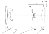
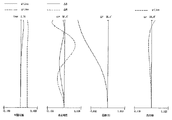
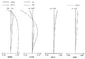
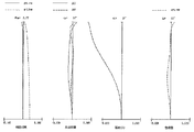
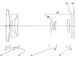
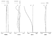
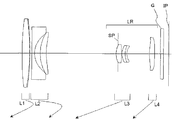
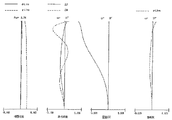
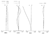
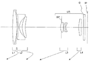
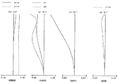
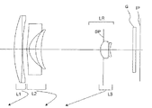
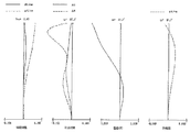
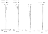
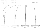
図1は、実施例1のズームレンズの広角端(短焦点距離端)における要部断面図(レンズ断面図)である。図2〜図4はそれぞれ実施例1のズームレンズの広角端、中間焦点距離、望遠端(長焦点距離端)における収差図である。 FIG. 1 is a cross-sectional view (lens cross-sectional view) of a main part at the wide angle end (short focal length end) of the zoom lens according to the first exemplary embodiment. Figures 2-4, respectively, at the wide angle end of the zoom lens in Example 1, is a diagram of aberrations in the intermediate focal length, a telephoto end (long focal length end).
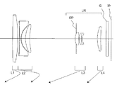
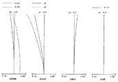
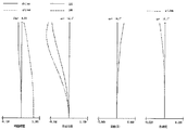
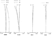
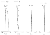
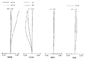
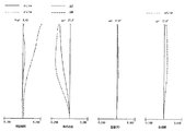
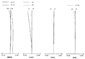
図5は、実施例2のズームレンズの広角端におけるレンズ要部断面図である。図6〜図8はそれぞれ実施例2のズームレンズの広角端、中間焦点距離、望遠端における収差図である。
FIG. 5 is a cross-sectional view of the main part of the zoom lens of
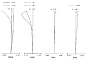
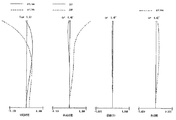
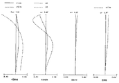
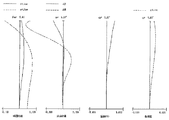
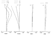
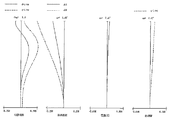
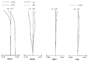
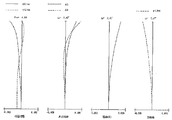
図9は、実施例3のズームレンズの広角端におけるレンズ要部断面図である。図10〜図12はそれぞれ実施例3のズームレンズの広角端、中間焦点距離、望遠端における収差図である。 FIG. 9 is a lens cross-sectional view of the lens at the wide-angle end of the zoom lens according to the third exemplary embodiment. 10 to 12 are aberration diagrams of the zoom lens of Example 3 at the wide-angle end, the intermediate focal length, and the telephoto end, respectively.
図13は、実施例4のズームレンズの広角端におけるレンズ要部断面図である。図14〜図16はそれぞれ実施例4のズームレンズの広角端、中間焦点距離、望遠端における収差図である。
FIG. 13 is a cross-sectional view of the main part of the zoom lens of
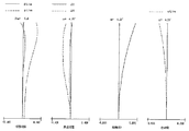
図17は、実施例5のズームレンズの広角端におけるレンズ要部断面図である。図18〜図20はそれぞれ実施例5のズームレンズの広角端、中間焦点距離、望遠端における収差図である。 FIG. 17 is a lens cross-sectional view of the zoom lens of Example 5 at the wide-angle end. 18 to 20 are aberration diagrams of the zoom lens of Example 5 at the wide-angle end, the intermediate focal length, and the telephoto end, respectively.
図21は、実施例6のズームレンズの広角端におけるレンズ要部断面図である。図22〜図24はそれぞれ実施例6のズームレンズの広角端、中間焦点距離、望遠端における収差図である。 FIG. 21 is a lens cross-sectional view of the zoom lens of Example 6 at the wide-angle end. 22 to 24 are aberration diagrams of the zoom lens of Example 6 at the wide-angle end, the intermediate focal length, and the telephoto end, respectively.
図25は、実施例7のズームレンズの広角端におけるレンズ要部断面図である。図26〜図28はそれぞれ実施例7のズームレンズの広角端、中間焦点距離、望遠端における収差図である。 FIG. 25 is a lens cross-sectional view of the zoom lens of Example 7 at the wide-angle end. 26 to 28 are aberration diagrams at the wide-angle end, the intermediate focal length, and the telephoto end, respectively, of the zoom lens according to the seventh embodiment.
図29は、実施例8のズームレンズの広角端におけるレンズ要部断面図である。図30〜図32はそれぞれ実施例8のズームレンズの広角端、中間焦点距離、望遠端における収差図である。 FIG. 29 is a lens cross-sectional view of the zoom lens of Example 8 at a wide angle end. 30 to 32 are aberration diagrams at the wide-angle end, the intermediate focal length, and the telephoto end, respectively, of the zoom lens according to the eighth embodiment.
図33は、実施例9のズームレンズの広角端におけるレンズ要部断面図である。図34〜図36はそれぞれ実施例9のズームレンズの広角端、中間焦点距離、望遠端における収差図である。 FIG. 33 is a lens cross-sectional view of the zoom lens of Example 9 at the wide-angle end. 34 to 36 are aberration diagrams at the wide-angle end, the intermediate focal length, and the telephoto end, respectively, of the zoom lens according to the ninth embodiment.
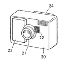
図37は本発明のズームレンズを備えるカメラ(撮像装置)の要部概略図である。 FIG. 37 is a schematic diagram of a main part of a camera (image pickup apparatus) including the zoom lens of the present invention.
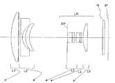
各実施例のズームレンズはビデオカメラやデジタルカメラ等の撮像装置に用いられる撮像レンズ系である。レンズ断面図において、左方が物体側(前方)で、右方が像側(後方)である。 The zoom lens of each embodiment is an imaging lens system used in an imaging apparatus such as a video camera or a digital camera. In the lens cross-sectional view, the left side is the object side (front), and the right side is the image side (rear).
尚、各実施例のズームレンズをプロジェクター等の投射レンズとして用いるときは、左方がスクリーン、右方が被投射画像となる。 When the zoom lens of each embodiment is used as a projection lens such as a projector, the left side is the screen and the right side is the projected image.
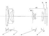
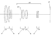
レンズ断面図において、iは物体側からのレンズ群の順番を示し、Liは第iレンズ群である。LRは1以上のレンズ群を含む後群である。 In the lens cross-sectional view, i indicates the order of the lens groups from the object side, and Li is the i-th lens group. LR is a rear group including one or more lens groups.
レンズ断面図においてL1は正の屈折力の第1レンズ群、L2は負の屈折力の第2レンズ群、L3は正の屈折力の第3レンズ群、L4は正の屈折力の第4レンズ群、L5は正の屈折力の第5レンズ群である。 In the lens cross-sectional view, L1 is a first lens group having a positive refractive power, L2 is a second lens group having a negative refractive power, L3 is a third lens group having a positive refractive power, and L4 is a fourth lens having a positive refractive power. The group L5 is a fifth lens group having a positive refractive power.
SPは開口絞り(Fナンバー決定絞り)である。開口絞りSPは実施例1〜7において第3レンズ群L3の最も物体側に配置したレンズの物体側頂点と該レンズの物体側の面と外周部との交点との間に配置している。 SP is an aperture stop (F-number determining stop). The aperture stop SP is disposed between the object-side vertex of the lens disposed closest to the object side of the third lens unit L3 in Embodiments 1 to 7, and the intersection of the object-side surface and the outer periphery of the lens.
実施例8、9では、第3レンズ群L3の物体側に配置している。 In Examples 8 and 9, the third lens unit L3 is disposed on the object side.
Gは光学フィルター、フェースプレート、水晶ローパスフィルター、赤外カットフィルター等に相当する光学ブロックである。 G is an optical block corresponding to an optical filter, a face plate, a quartz low-pass filter, an infrared cut filter, or the like.
IPは像面であり、ビデオカメラやデジタルスチルカメラの撮像光学系として使用する際にはCCDセンサやCMOSセンサなどの固体撮像素子(光電変換素子)の撮像面が置かれている。 IP is an image plane. When used as an imaging optical system of a video camera or a digital still camera, an imaging plane of a solid-state imaging device (photoelectric conversion device) such as a CCD sensor or a CMOS sensor is placed.
又、銀塩フィルム用のカメラの撮像光学系として使用する際には、フィルム面に相当する。 Further, when used as an imaging optical system of a silver salt film camera, it corresponds to a film surface.
収差図において、d、gは各々d線及びg線、ΔM、ΔSはメリディオナル像面、サジタル像面、倍率色収差はg線によって表している。ωは半画角、FnoはFナンバーである。 In the aberration diagrams, d and g are d-line and g-line, respectively, ΔM and ΔS are meridional image surface, sagittal image surface, and lateral chromatic aberration are represented by g-line. ω is a half angle of view, and Fno is an F number.
尚、以下の各実施例において広角端と望遠端は変倍用レンズ群が機構上光軸上を移動可能な範囲の両端に位置した時のズーム位置をいう。 In the following embodiments, the wide-angle end and the telephoto end refer to zoom positions when the zoom lens unit is positioned at both ends of the range in which the mechanism can move on the optical axis.
矢印は、広角端から望遠端へのズーミングにおける各レンズ群の移動軌跡を示している。 The arrows indicate the movement trajectory of each lens unit during zooming from the wide-angle end to the telephoto end.
広角端から望遠端へのズーミングに際し、第1レンズ群L1は広角端に比べて望遠端において物体側に位置するように移動する。 During zooming from the wide-angle end to the telephoto end, the first lens unit L1 moves so as to be positioned closer to the object side at the telephoto end than at the wide-angle end.
前記第2レンズ群は第1レンズ群L1と第2レンズ群L2の間隔が大きくなるように移動する。 The second lens group moves so that the distance between the first lens group L1 and the second lens group L2 is increased.
第3レンズ群L3は第2レンズ群L2と第3レンズ群L3の間隔が小さくなるように移動する。 The third lens unit L3 moves so that the distance between the second lens unit L2 and the third lens unit L3 is small.
各実施例のズームレンズは物体側より像側へ順に、正の屈折力の第1レンズ群L1、負の屈折力の第2レンズ群L2、1以上のレンズ群を含む後群LRより構成している。そして第2レンズ群L2を2枚のレンズで構成しながらも透光性セラミックスより成る屈折率の高い材料を使用することにより、高ズーム比で、高い光学性能を有した小型のズームレンズを達成している。 The zoom lens according to each embodiment includes, in order from the object side to the image side, a first lens unit L1 having a positive refractive power, a second lens unit L2 having a negative refractive power, and a rear unit LR including one or more lens units. ing. By using a material with a high refractive index made of translucent ceramics while constituting the second lens unit L2 with two lenses, a small zoom lens having a high zoom ratio and high optical performance is achieved. doing.
また、第2レンズ群L2は両凹形状又は物体側が凸でメニスカス形状の負レンズと物体側が凸でメニスカス形状の正レンズで構成している。この負レンズに高屈折率の材料を使用することにより、各レンズ面の曲率を緩くすることでコマ収差、像面湾曲等の諸収差の発生を低減し、又、光学素子自体の薄型化を図っている。 The second lens unit L2 includes a biconcave lens or a negative meniscus lens having a convex object side and a positive meniscus lens having a convex object side. By using a material with a high refractive index for this negative lens, the occurrence of various aberrations such as coma and curvature of field is reduced by loosening the curvature of each lens surface, and the optical element itself is made thinner. I am trying.
負レンズの少なくとも1面を非球面形状としている。このときの非球面形状は物体側の面が非球面形状のときは軸外へ向かって負の屈折力を強める形状とすることにより、軸外でアンダーに出る像面湾曲を補正している。 At least one surface of the negative lens is aspherical. In this case, when the object side surface is an aspherical shape, the aspherical shape is a shape that increases the negative refractive power toward the off-axis, thereby correcting the curvature of field that goes under the off-axis.
また、像面側の面が非球面形状のときは物体側の面により生じる樽型の歪曲を打ち消すために、軸外へ向かって負のパワーが弱くなる形状としている。 Further, when the image side surface is aspherical, in order to cancel barrel distortion caused by the object side surface, the negative power decreases toward the off-axis.
尚、非球面は、母材(レンズ)に直接形成する他、母材に樹脂材料(レプリカ)を積層して形成しても良い。 The aspherical surface may be formed directly on the base material (lens) or may be formed by laminating a resin material (replica) on the base material.
一方、第2レンズ群L2中のメニスカス形状の正レンズは第2レンズ群内の色収差を補正するためには負レンズよりも高分散な材料が必要となる。 On the other hand, the meniscus positive lens in the second lens unit L2 requires a material having higher dispersion than the negative lens in order to correct chromatic aberration in the second lens unit.
前述したとおり、光学ガラスは屈折率が大きくなるほど高分散になる傾向がある。セラミックスや酸化物の単結晶および多結晶は屈折率が高くなっても比較的、低分散である。このためこれらの材料を使用することによって、色収差を補正しつつ、全系の小型化を実現している。 As described above, optical glass tends to be highly dispersed as the refractive index increases. Ceramics and oxide single crystals and polycrystals have relatively low dispersion even when the refractive index increases. Therefore, by using these materials, it is possible to reduce the size of the entire system while correcting chromatic aberration.
一般に光学ガラスは、屈折率を縦軸に上方向が大きな値となるように、アッベ数を横軸に左方向が大きな値となるように取ったグラフ(以下「nd−νd図」と呼ぶ)上にマッピングさせると、ほぼいくつかの直線に沿って分布することが知られている。また一般に光学ガラスの屈折率が大きくなると、アッベ数は小さくなり、分散が大きくなる特性がある。 In general, optical glass is a graph in which the refractive index is taken to be a large value on the vertical axis and the Abbe number is taken to be a large value on the left side on the horizontal axis (hereinafter referred to as “nd-νd diagram”). When mapped up, it is known to be distributed along almost several straight lines. In general, when the refractive index of the optical glass increases, the Abbe number decreases and the dispersion increases.
これに対して、可視光領域で光透過率の高いセラミックスや酸化物の単結晶および多結晶の中には、屈折率とアッベ数の関係が、前述のnd−νd図において通常の光学ガラスとは異なる領域に存在するものが知られている。すなわち同じアッベ数を有する光学ガラスに比べ、高い屈折率を有する材料が知られている。 On the other hand, among single crystals and polycrystals of ceramics and oxides having high light transmittance in the visible light region, the relationship between the refractive index and the Abbe number is different from that of ordinary optical glass in the nd-νd diagram described above. Are known to exist in different regions. That is, a material having a higher refractive index than that of optical glass having the same Abbe number is known.
本発明では、このような材料を第2レンズ群L2の正レンズと負レンズの少なくとも1つの材料に用いている。 In the present invention, such a material is used for at least one material of the positive lens and the negative lens of the second lens unit L2.
そして、各実施例において、第2レンズ群L2を構成する負レンズの少なくとも1つの材料のd線に対する屈折率とアッベ数を各々N2n、ν2nとする。第2レンズ群L2を構成する正レンズのd線に対する屈折率をN2pとする。このとき、
2.45<N2n−(9.3×10⁻⁵×ν2n2−1.70×10⁻²×ν2n)<3.00 ・・・(1)
5<ν2n<80 ・・・(2)
1.98<(N2n+N2p)/2<2.25 ・・・(3)
の条件を満足している。
In each embodiment, the refractive index and Abbe number of at least one material of the negative lens constituting the second lens unit L2 with respect to the d-line are N2n and ν2n, respectively. The refractive index with respect to the d-line of the positive lens constituting the second lens unit L2 is N2p. At this time,
2.45 <N2n− (9.3 × 10 −5 × ν2n 2 −1.70 × 10 −2 × ν2n) <3.00 (1)
5 <ν2n <80 (2)
1.98 <(N2n + N2p) / 2 <2.25 (3)
The conditions are satisfied.
次に前述の各条件式の技術的意味について説明する。 Next, the technical meaning of each conditional expression described above will be described.
条件式(1)は第2レンズL2の負レンズの材料のd線における屈折率及びアッベ数との関係を規定している。屈折率が条件式(1)の下限を下回り、負レンズの屈折率が小さくなると屈折力も小さくなり十分なズーム比を得るために第2レンズ群L2の移動量が大きくなり、レンズ系が大型化してくる。 Conditional expression (1) defines the relationship between the refractive index and the Abbe number at the d-line of the material of the negative lens of the second lens L2. If the refractive index falls below the lower limit of conditional expression (1) and the refractive index of the negative lens decreases, the refractive power also decreases and the amount of movement of the second lens unit L2 increases to obtain a sufficient zoom ratio, and the lens system becomes larger. Come.
また、条件式(1)の上限を超えて負レンズの材料の屈折率が高くなると、ペッツバール和をマイナス方向に補正する効果が弱くなり像面がアンダー側に倒れてくるので良くない。 Further, if the refractive index of the negative lens material increases beyond the upper limit of conditional expression (1), the effect of correcting the Petzval sum in the negative direction becomes weak and the image surface falls to the under side, which is not good.
条件式(2)は第2レンズ群L2の負レンズの材料のd線におけるアッベ数を規定している。アッベ数が条件式(2)の下限を下回ると、第2レンズ群L2内の色収差を補正するために正レンズの材料としてより高分散な材料を選択することができなくなり、特に広角端における倍率色収差の補正が困難となる。また、条件式(2)の上限を超えて負レンズが低分散になると、広角端における倍率色収差が補正過剰となるためよくない。 Conditional expression (2) defines the Abbe number in the d-line of the material of the negative lens of the second lens unit L2. If the Abbe number is below the lower limit of the conditional expression (2), it is not possible to select a higher dispersion material as the positive lens material in order to correct the chromatic aberration in the second lens unit L2, and in particular, the magnification at the wide angle end. Correction of chromatic aberration becomes difficult. Also, if the negative lens becomes low dispersion exceeding the upper limit of conditional expression (2), the lateral chromatic aberration at the wide-angle end will be overcorrected, which is not good.
条件式(3)は第2レンズ群L2を構成するレンズの材料の平均屈折率を規定している。平均屈折率が条件式(3)の下限を下回ると負レンズと正レンズのレンズ面の曲率が小さくなり、各レンズ面で大きな高次収差が発生し、光学性能が悪化してくる。 Conditional expression (3) defines the average refractive index of the material of the lenses constituting the second lens unit L2. When the average refractive index is below the lower limit of the conditional expression (3), the curvature of the lens surfaces of the negative lens and the positive lens becomes small, large high-order aberrations occur on each lens surface, and the optical performance deteriorates.
さらに、各レンズの肉厚(厚さ)が長くなり、第2レンズ群L2全体の光軸上の長さが増大してくる。また、条件式(3)の上限を超えて平均屈折率が大きくなるとペッツバール和をマイナス方向に補正する効果が弱くなり、像面特性がアンダー側に倒れてくるので良くない。 Further, the thickness (thickness) of each lens becomes longer, and the length of the entire second lens unit L2 on the optical axis increases. Further, if the average refractive index increases beyond the upper limit of the conditional expression (3), the effect of correcting the Petzval sum in the minus direction becomes weak, and the image plane characteristic falls to the under side, which is not good.
尚、更に好ましくは条件式(2)、(3)の数値範囲を次の如く設定するのが良い。 More preferably, the numerical ranges of conditional expressions (2) and (3) should be set as follows.
30<ν2n<55 ・・・(2a)
2.00<(N2n+N2p)/2<2.20 ・・・(3a)
以上のように、各要素を構成することによって、各実施例では高ズーム比と高い光学性能を有しながらも第2レンズ群を2枚のレンズで構成することができ、これによりズームレンズの小型化を達成している。
30 <ν2n <55 (2a)
2.00 <(N2n + N2p) / 2 <2.20 (3a)
As described above, by configuring each element, in each embodiment, the second lens group can be configured by two lenses while having a high zoom ratio and high optical performance. Miniaturization has been achieved.
以上の諸条件を満足することによって、高ズーム比で全ズーム範囲にわたり高い光学性能を有するズームレンズを得ている。 By satisfying the above conditions, a zoom lens having a high zoom ratio and high optical performance over the entire zoom range is obtained.
各実施例において、更に良好なる収差補正を行い、かつズーミングの際の収差変動を小さくしつつ、レンズ系全体の小型化を図るには、次の諸条件のうち、1以上を満足するのが良い。 In each embodiment, in order to further reduce aberrations during zooming while reducing aberration variation during zooming, one or more of the following conditions must be satisfied. good.
第2レンズ群L2の最も物体側の面から、最も像側の面までの距離をD2とする。ズームレンズの広角端と望遠端における焦点距離を各々fw、ftとする。 The distance from the most object side surface of the second lens unit L2 to the most image side surface is defined as D2. The focal lengths at the wide-angle end and the telephoto end of the zoom lens are fw and ft, respectively.
第2レンズ群L2の正レンズのd線におけるアッベ数をν2pとする。 The Abbe number at the d-line of the positive lens of the second lens unit L2 is ν2p.
第2レンズ群L2の負レンズと正レンズの焦点距離を各々f2n、f2pとする。 The focal lengths of the negative lens and the positive lens of the second lens unit L2 are f2n and f2p, respectively.
第2レンズ群L2の広角端と望遠端における横倍率を各々β2w、β2tとする。 The lateral magnifications at the wide-angle end and the telephoto end of the second lens unit L2 are β2w and β2t, respectively.
後群LRは、正の屈折力の第3レンズ群L3を有しており、第3レンズ群L3の広角端と望遠端における横倍率を各々β3w、β3tとする。 The rear group LR includes a third lens unit L3 having a positive refractive power, and the lateral magnifications at the wide-angle end and the telephoto end of the third lens unit L3 are β3w and β3t, respectively.
第1レンズ群L1と第2レンズ群L2の焦点距離を各々f1、f2とする。 The focal lengths of the first lens unit L1 and the second lens unit L2 are f1 and f2, respectively.
このとき
0.05<D2/fw<1.2 ・・・(4)
1.98<ν2n/ν2p<3.2 ・・・(5)
−0.4<f2n/f2p<−0.2 ・・・(6)
2.8<ft/fw<10 ・・・(7)
1.5<|β2t/β2w|<3.2 ・・・(8)
0.3<|β3t/β3w|<7.1 ・・・(9)
−2.5<f2/fw<−0.5 ・・・(10)
−6.8<f1/f2<−1.7 ・・・(11)
なる条件のうち1以上を満足するのが良い。
At this time, 0.05 <D2 / fw <1.2 (4)
1.98 <ν2n / ν2p <3.2 (5)
−0.4 <f2n / f2p <−0.2 (6)
2.8 <ft / fw <10 (7)
1.5 <| β2t / β2w | <3.2 (8)
0.3 <| β3t / β3w | <7.1 (9)
−2.5 <f2 / fw <−0.5 (10)
−6.8 <f1 / f2 <−1.7 (11)
It is preferable to satisfy one or more of the following conditions.
次に各条件式の技術的意味について説明する。 Next, the technical meaning of each conditional expression will be described.
条件式(4)は第2レンズ群L2の光軸上の厚みを規定している。第2レンズ群L2の厚みが条件式(4)の下限を下回ると、負レンズと正レンズが互いに干渉してしまうためレンズ面に所定の屈折力の曲率が付けることが難しくなり、収差補正を良好に行うのが困難となる。 Conditional expression (4) defines the thickness of the second lens unit L2 on the optical axis. If the thickness of the second lens unit L2 is less than the lower limit of the conditional expression (4), the negative lens and the positive lens interfere with each other, making it difficult to give a curvature of a predetermined refractive power to the lens surface. It becomes difficult to perform well.
特に広角端における倍率色収差や像面湾曲、望遠端におけるコマ収差が補正不足となる。また、第2レンズ群L2の厚みが条件式(4)の上限を上回ると、第2レンズ群L2が厚くなりすぎて沈胴方式を用いたとき沈胴長を短縮することが難しくなる。 In particular, lateral chromatic aberration and field curvature at the wide-angle end, and coma at the telephoto end are insufficiently corrected. On the other hand, if the thickness of the second lens unit L2 exceeds the upper limit of the conditional expression (4), the second lens unit L2 becomes too thick and it becomes difficult to shorten the retracted length when the retracting method is used.
条件式(5)は第2レンズ群L2の負レンズと正レンズの材料のd線におけるアッベ数の関係を規定している。第2レンズ群L2の負レンズと正レンズの材料のd線におけるアッベ数の比が条件式(5)の下限を下回ると、広角端における倍率色収差が補正不足となり、これを補正しようとすると第2レンズ群L2の厚さが増大してしまう。また、第2レンズ群L2の負レンズと正レンズの材料のd線におけるアッベ数の比が条件式(5)の上限を上回ると、広角端における倍率色収差が補正過剰となる。 Conditional expression (5) defines the relationship between the Abbe numbers in the d-line of the materials of the negative lens and the positive lens of the second lens unit L2. If the ratio of the Abbe number in the d-line of the negative lens and the positive lens material of the second lens unit L2 is below the lower limit of the conditional expression (5), the lateral chromatic aberration at the wide-angle end becomes insufficiently corrected. The thickness of the two lens unit L2 increases. Further, if the ratio of the Abbe number in the d-line of the material of the negative lens and the positive lens in the second lens unit L2 exceeds the upper limit of the conditional expression (5), the lateral chromatic aberration at the wide angle end becomes overcorrected.
条件式(6)は第2レンズ群L2の負レンズと正レンズの屈折力(焦点距離の逆数)の比を規定している。負レンズの焦点距離の絶対値が正レンズの焦点距離に対して長くなり、条件式(6)の下限を下回ると前玉径(第1レンズ群L1)が増大し、全系の小型化が困難となる。また、負レンズの焦点距離の絶対値が正レンズの焦点距離に対して短くなり、条件式(6)の上限を上回ると広角端において軸外で発生する諸収差が大きくなり、特に広角端において倍率色収差や歪曲収差の補正が困難となる。 Conditional expression (6) defines the ratio of the refractive power (reciprocal of focal length) of the negative lens and the positive lens of the second lens unit L2. When the absolute value of the focal length of the negative lens becomes longer than the focal length of the positive lens and falls below the lower limit of the conditional expression (6), the front lens diameter (first lens unit L1) increases and the entire system can be downsized. It becomes difficult. Further, when the absolute value of the focal length of the negative lens becomes shorter than the focal length of the positive lens and exceeds the upper limit of the conditional expression (6), various aberrations that occur off-axis at the wide-angle end become large, especially at the wide-angle end. Correction of lateral chromatic aberration and distortion is difficult.
条件式(7)は全系のズーム比に関するものである。条件式(7)は各実施例のズーム範囲を明確にし、所定の材料を使用した際に高ズーム比で、高い光学性能を有し、かつ全系の小型化を最も効果的に達成することのできる範囲を指定している。ここでズーム比は変培に際して配置される各レンズ群の屈折力やズーミングの際の移動範囲等に依存している。 Conditional expression (7) relates to the zoom ratio of the entire system. Conditional expression (7) clarifies the zoom range of each embodiment, has a high zoom ratio when using a predetermined material, has high optical performance, and achieves the most effective miniaturization of the entire system. The range that can be used is specified. Here, the zoom ratio depends on the refracting power of each lens group arranged during alteration, the movement range during zooming, and the like.
条件式(8)と条件式(9)は第2レンズ群L2、第3レンズ群L3の適度な変倍作用の範囲を規定するものである。条件式(8)の下限を下回るか条件式(9)の上限を上回ると、高ズーム比を得ようとした際、第3レンズ群L3の変倍作用が強くなりすぎて諸収差の補正が困難となり、又、製造の際の敏感度が高くなってくるので良くない。 Conditional expression (8) and conditional expression (9) define an appropriate range of zooming action of the second lens unit L2 and the third lens unit L3. If the lower limit of conditional expression (8) is exceeded or the upper limit of conditional expression (9) is exceeded, the zooming action of the third lens unit L3 becomes too strong to correct various aberrations when trying to obtain a high zoom ratio. It becomes difficult, and the sensitivity at the time of manufacturing becomes high, so it is not good.
また、条件式(8)の上限を上回るか条件式(9)の下限を下回ると、高ズーム比を得ようとした際、第2レンズ群L2の変倍作用が強くなりすぎて諸収差の補正が困難となり、又、製造の際の敏感度が高くなってくるので良くない。また、第3レンズ群L3に大きな変倍分担を与えることにより、第2レンズ群L2はズーミングに際して像側に凸状の軌跡を描いて移動するようになる。 On the other hand, if the upper limit of conditional expression (8) is exceeded or the lower limit of conditional expression (9) is exceeded, the zooming action of the second lens unit L2 becomes too strong when trying to obtain a high zoom ratio, and various aberrations occur. It is not good because correction becomes difficult and the sensitivity in manufacturing increases. Further, by giving a large zooming share to the third lens unit L3, the second lens unit L2 moves with a convex locus on the image side during zooming.
第2レンズ群L2が直線的に像側に移動する場合に比べて、第2レンズ群L2の像側への移動スペースを確保する必要性が少なくなるため、広角端における第2レンズ群L2の位置をより開口絞りSPに近く配置することができる。その結果、前玉径を小さく抑えることが容易となる。 Compared with the case where the second lens unit L2 moves linearly to the image side, it is less necessary to secure a space for moving the second lens unit L2 to the image side. The position can be arranged closer to the aperture stop SP. As a result, it becomes easy to keep the front lens diameter small.
条件式(10)は広角端における全系の焦点距離に対する第2レンズ群L2の焦点距離の比を規定している。第2レンズ群L2の焦点距離が条件式(10)の下限を下回り、屈折力が弱くなると十分なズーム比を得るために第2レンズ群L2の移動量が大きくなり、全系が大型化してくる。また、第2レンズ群L2の焦点距離が条件式(10)の上限を上回り、屈折力が強くなると、望遠端におけるコマ収差の補正が困難となる。さらに、第2レンズ群L2中の負レンズの偏肉比が大きくなり、製造が困難となる。また、レンズ面の曲率がきつくなることに起因して各レンズの肉厚が長くなるため第2レンズ群L2全体の厚さが増大してくる。 Conditional expression (10) defines the ratio of the focal length of the second lens unit L2 to the focal length of the entire system at the wide angle end. If the focal length of the second lens unit L2 falls below the lower limit of the conditional expression (10) and the refractive power becomes weak, the movement amount of the second lens unit L2 increases to obtain a sufficient zoom ratio, and the entire system increases in size. come. Further, when the focal length of the second lens unit L2 exceeds the upper limit of the conditional expression (10) and the refractive power becomes strong, it becomes difficult to correct coma at the telephoto end. Furthermore, the thickness deviation ratio of the negative lens in the second lens unit L2 becomes large, and manufacturing becomes difficult. Further, since the thickness of each lens becomes longer due to the tight curvature of the lens surface, the entire thickness of the second lens unit L2 increases.
条件式(11)は第1レンズ群L1と第2レンズ群L2の焦点距離の比を規定している。条件式(11)の下限を下回ると望遠端におけるFナンバーが大きくなってくるので良くない。また、条件式(11)の上限を上回ると、前玉径が増大し、全系が大型化してくるので良くない。 Conditional expression (11) defines the ratio of the focal lengths of the first lens unit L1 and the second lens unit L2. If the lower limit of conditional expression (11) is not reached, the F number at the telephoto end will increase, which is not good. On the other hand, if the upper limit of conditional expression (11) is exceeded, the front lens diameter will increase and the entire system will become larger, which is not good.
なお、更に好ましくは条件式(4)〜(11)の数値範囲を次の如く設定するのが良い。 More preferably, the numerical ranges of the conditional expressions (4) to (11) are set as follows.
0.78<D2/fw<1.10 ・・・(4a)
2.0<ν2n/ν2p<3.15 ・・・(5a)
−0.39<f2n/f2p<−0.22 ・・・(6a)
5.8<ft/fw<9 ・・・(7a)
1.6<|β2t/β2w|<2.1 ・・・(8a)
4.3<|β3t/β3w|<7.1 ・・・(9a)
−2.2<f2/fw<−1.6 ・・・(10a)
−6.1<f1/f2<−4.5 ・・・(11a)
次に本発明のズームレンズの各実施例のレンズ構成について説明する。
0.78 <D2 / fw <1.10 (4a)
2.0 <ν2n / ν2p <3.15 (5a)
−0.39 <f2n / f2p <−0.22 (6a)
5.8 <ft / fw <9 (7a)
1.6 <| β2t / β2w | <2.1 (8a)
4.3 <| β3t / β3w | <7.1 (9a)
-2.2 <f2 / fw <-1.6 (10a)
−6.1 <f1 / f2 <−4.5 (11a)
Next, the lens configuration of each embodiment of the zoom lens of the present invention will be described.
図1の実施例1は、物体側より像側へ順に、正の屈折力の第1レンズ群L1、負の屈折力の第2レンズ群L2、正の屈折力の第3レンズ群L3、正の屈折力の第4レンズ群L4で構成されている。 In Example 1 of FIG. 1, in order from the object side to the image side, a first lens unit L1 having a positive refractive power, a second lens unit L2 having a negative refractive power, a third lens unit L3 having a positive refractive power, The fourth lens unit L4 having a refractive power of 5 mm.
広角端から望遠端へのズーミングに際して、第1レンズ群L1は像側に凸状の軌跡に沿って移動し、第2レンズ群L2は像側に凸状の軌跡に沿って移動する。また、広角端から望遠端へのズーミングに際して、第3レンズ群L3は物体側へ移動して主たる変倍を行い、第4レンズ群L4は物体側へ移動して変倍に伴う像面変動を低減(補正)している。第1レンズ群L1を広角端からズーム範囲の略中間位置まで像側へ移動させることにより開口絞りSPとの距離を短くして前玉径の小径化を図っている。 During zooming from the wide-angle end to the telephoto end, the first lens unit L1 moves along a locus convex to the image side, and the second lens unit L2 moves along a locus convex to the image side. Further, during zooming from the wide-angle end to the telephoto end, the third lens unit L3 moves to the object side to perform main zooming, and the fourth lens unit L4 moves to the object side to change the image plane due to zooming. Reduced (corrected). By moving the first lens unit L1 from the wide-angle end to a substantially intermediate position in the zoom range toward the image side, the distance from the aperture stop SP is shortened to reduce the diameter of the front lens.
第1レンズ群は、物体側から順に、正レンズ(第1光学素子)(像側に屈折面が物体側の屈折面よりも正のパワーが強い)と、その正レンズに接合された負の屈折力を持つ光学素子(第2光学素子)を有する複合光学素子を備えている。第2光学素子は樹脂材料から成ることが好ましい。このように、第1レンズ群が正レンズと、それに接合された負の屈折力を持つ光学素子を有する複合光学素子によって構成されている点については、後述する実施例3、4、5、6、8も同じである。 The first lens group includes, in order from the object side, a positive lens (first optical element) (a refracting surface on the image side has a stronger positive power than a refracting surface on the object side) and a negative lens joined to the positive lens. A composite optical element having an optical element having a refractive power (second optical element) is provided. The second optical element is preferably made of a resin material. As described above, the point that the first lens group is composed of a positive lens and a composite optical element having an optical element having negative refractive power joined thereto is described in Examples 3, 4, 5, and 6 described later. , 8 is the same.
本実施例において、複合光学素子は第1光学素子とこの第1光学素子G11に接合された第2光学素子G12(複数でも構わない)とによって構成されている。この第1光学素子G11と、この第1光学素子に接合された第2光学素子(好ましくは樹脂で構成されている補助レンズ)G12とが以下の関係を満足する。 In this embodiment, the composite optical element is composed of a first optical element and a second optical element G12 (a plurality of optical elements may be joined) joined to the first optical element G11. The first optical element G11 and the second optical element (preferably an auxiliary lens made of resin) G12 bonded to the first optical element satisfy the following relationship.
(ア)第1光学素子の光軸上の厚さは、第2光学素子の光軸上の厚さの3倍以上(好ましくは5倍以上)である。ここで、第1光学素子の光軸上の厚さは、第2光学素子の光軸上の厚さの100倍以下であると好ましい。 (A) The thickness of the first optical element on the optical axis is at least three times (preferably at least five times) the thickness of the second optical element on the optical axis. Here, the thickness of the first optical element on the optical axis is preferably 100 times or less the thickness of the second optical element on the optical axis.
(イ)第1光学素子の屈折力(焦点距離の逆数)の絶対値は、第2光学素子の屈折力の絶対値の2倍以上(好ましくは2.5倍以上)である。ここで、第1光学素子の屈折力(焦点距離の逆数)の絶対値は、第2光学素子の屈折力の絶対値の50倍以下(好ましくは40倍以下)である。 (A) The absolute value of the refractive power (the reciprocal of the focal length) of the first optical element is at least twice (preferably at least 2.5 times) the absolute value of the refractive power of the second optical element. Here, the absolute value of the refractive power (the reciprocal of the focal length) of the first optical element is 50 times or less (preferably 40 times or less) the absolute value of the refractive power of the second optical element.
第2レンズ群L2は、物体側から順に、両凹形状の負レンズと物体側が凸でメニスカス形状の正レンズで構成している。負レンズにセラミックス等の屈折率N2nが1.97500、アッベ数がν2nが39.5の材料を用いている。負レンズの材料は高屈折率であるので、レンズ面が同じ曲率であれば負レンズの屈折力を強めても収差の発生を抑えられる。このため高ズーム比化が容易で、同じ倍率であればレンズ面の曲率を緩くすることができ、これにより、光学性能の高性能化及び第2レンズ群L2の薄型化を容易にしている。 The second lens unit L2 includes, in order from the object side, a biconcave negative lens and a meniscus positive lens convex on the object side. A material such as ceramics having a refractive index N2n of 1.97500 and an Abbe number of ν2n of 39.5 is used for the negative lens. Since the negative lens material has a high refractive index, if the lens surface has the same curvature, the occurrence of aberration can be suppressed even if the refractive power of the negative lens is increased. For this reason, it is easy to increase the zoom ratio, and if the magnification is the same, the curvature of the lens surface can be relaxed. This makes it easy to improve the optical performance and reduce the thickness of the second lens unit L2.
この材料(セラミックス)は、一般の光学ガラス材料よりも高屈折率ににもかかわらずアッベ数が大きいため(分散が小さいため)、広角端における倍率色収差を良好に補正することができる。 This material (ceramics) has a higher Abbe number (because of less dispersion) despite a higher refractive index than a general optical glass material, so that it is possible to satisfactorily correct lateral chromatic aberration at the wide-angle end.
さらに、本実施例においては正レンズに株式会社住田光学ガラスのk−PSFn214(商品名)等の屈折率N2pが2.14352、アッベ数がν2pが17.8の材料を用いている。これにより、正レンズによる高倍化、光学性能の高性能化、全系の小型化を図っている。広角端における倍率色収差を、負レンズと正レンズを用いて補正するとき、本実施例では正レンズの材料に高屈折率、高分散材料を使用している。これにより全系の小型化と収差補正を効果的に行っている。 Further, in this embodiment, a material having a refractive index N2p of 2.14352 and an Abbe number of ν2p of 17.8, such as k-PSFn214 (trade name) of Sumita Optical Glass Co., Ltd., is used for the positive lens. As a result, high magnification with a positive lens, high performance of optical performance, and downsizing of the entire system are achieved. When correcting lateral chromatic aberration at the wide-angle end using a negative lens and a positive lens, in this embodiment, a high refractive index and high dispersion material is used as the material of the positive lens. This effectively reduces the size of the entire system and corrects aberrations.
第2レンズ群L2のレンズに高屈折率材料を使用することにより、第2レンズ群L2の変倍作用を強くして、他のレンズ群の変倍分担量を抑えて偏心敏感度の低いズームレンズを実現している。 By using a high refractive index material for the lens of the second lens unit L2, the zooming effect of the second lens unit L2 is strengthened, and the zooming amount with low eccentricity sensitivity is suppressed by suppressing the amount of zooming of other lens units. The lens is realized.
本実施例においては第2レンズ群L2の負レンズの両面を非球面形状とすることで、像面湾曲、歪曲収差を良好に補正している。さらに第2レンズ群L2の正レンズも両面を非球面形状とすることにより、望遠端においてコマ収差を良好に補正している。 In the present embodiment, the both sides of the negative lens of the second lens unit L2 are aspherical so that the field curvature and distortion are corrected well. Further, the positive lens of the second lens unit L2 is also aspherical on both sides, so that coma is corrected well at the telephoto end.
また、本実施例においては無限遠物体から近距離物体へフォーカスを行う場合には、第4レンズ群L4を前方に繰り出すことで行っている。 In this embodiment, when focusing from an object at infinity to an object at a short distance, the fourth lens unit L4 is moved forward.
尚、本明細書において、主たる変倍を行っているレンズ群とは広角端から望遠端へのズーミングに際して結像倍率の変化の比が、他の全てのレンズ群に比べて最も大きい値を有するレンズ群をいう。 In this specification, the main zooming lens group has the largest ratio of change in imaging magnification during zooming from the wide-angle end to the telephoto end as compared with all other lens groups. A lens group.
図5の実施例2はレンズ群の数や各レンズ群の屈折力の符号やズーミングにおける各レンズ群の移動条件等の基本レンズ構成は図1の実施例1と同じである。 Example 2 in FIG. 5 has the same basic lens configuration as Example 1 in FIG. 1 such as the number of lens groups, the sign of the refractive power of each lens group, and the movement conditions of each lens group during zooming.
第2レンズ群L2の負レンズにイットリウム・アルミニウム・ガーネット等の酸化物系セラミックス材料等の屈折率N2nが1.98730、アッベ数ν2nが36.6の材料を用いている。この負レンズ(第1光学素子)の物体側及び像側(いずれか一方でも構わない)には、負の屈折力を有する光学素子(第2光学素子)(好ましくは樹脂材料から成ることが望ましい)が配置されている。また、これらの負の屈折力を有する光学素子は、第2レンズ群の負レンズに対して接合されている。 The negative lens of the second lens unit L2 is made of a material having a refractive index N2n of 1.98730 and an Abbe number ν2n of 36.6, such as an oxide ceramic material such as yttrium, aluminum, and garnet. On the object side and the image side (either one of them) of the negative lens (first optical element), an optical element (second optical element) having negative refractive power (preferably made of a resin material is desirable. ) Is arranged. These optical elements having negative refractive power are cemented to the negative lens of the second lens group.
第2レンズ群L2の負レンズの物体側と像側に設けた光学素子の空気と接する面は非球面形状である。第2レンズ群の正レンズの物体側と像側の面は非球面形状である。 The surfaces of the optical elements provided on the object side and the image side of the negative lens of the second lens unit L2 that are in contact with air have an aspherical shape. The object side and image side surfaces of the positive lens in the second lens group are aspherical.
第2レンズ群L2の正レンズに株式会社住田光学ガラスのk−PSFn214(商品名)等の屈折率N2pが2.14352、アッベ数ν2pが17.8の材料を用いている。これらの材料により高倍化、光学性能の高性能化、全系の小型化を図っており、このことは、実施例1と同様である。 A material having a refractive index N2p of 2.14352 and an Abbe number ν2p of 17.8, such as k-PSFn214 (trade name) of Sumita Optical Glass Co., Ltd., is used for the positive lens of the second lens unit L2. These materials are intended to increase the magnification, increase the optical performance, and reduce the size of the entire system. This is the same as in the first embodiment.
本実施例においては第2レンズ群L2の負レンズの両面を非球面形状とすることで、像面湾曲、歪曲収差を良好に補正している。さらに第2レンズ群L2の正レンズも両面を非球面形状とすることにより、望遠端においてコマ収差を良好に補正している。 In the present embodiment, the both sides of the negative lens of the second lens unit L2 are aspherical so that the field curvature and distortion are corrected well. Further, the positive lens of the second lens unit L2 is also aspherical on both sides, so that coma is corrected well at the telephoto end.
本実施例におけるズームレンズは、高屈折材料に樹脂材料を用いて非球面を成型することにより、製造を容易にしている。また、無限遠物体から近距離物体へフォーカスを第4レンズ群L4を前方に繰り出すことで行っている。 The zoom lens according to the present embodiment is easily manufactured by molding an aspheric surface using a resin material as a high refractive material. Further, focusing from an infinitely distant object to a close object is performed by moving the fourth lens unit L4 forward.
図9の実施例3は、レンズ群の数や各レンズ群の屈折力の符号やズーミングにおける各レンズ群の移動条件等の基本レンズ構成は図1の実施例1と同じである。 Example 3 in FIG. 9 has the same basic lens configuration as Example 1 in FIG. 1 such as the number of lens groups, the sign of the refractive power of each lens group, and the movement conditions of each lens group during zooming.
第2レンズ群L2の負レンズにイットリウム・アルミニウム・ガーネット等の酸化物系セラミックス材料等の屈折率N2nが2.16250、アッベ数ν2nが34.8の材料を用いている。 A material having a refractive index N2n of 2.16250 and an Abbe number ν2n of 34.8, such as an oxide ceramic material such as yttrium, aluminum, and garnet, is used for the negative lens of the second lens unit L2.
第2レンズ群L2の正レンズにKT結晶(KTaO3)等の屈折率N2pが2.23260、アッベ数ν2pが16.9の材料を用いている。 A material having a refractive index N2p of 2.33260 and an Abbe number ν2p of 16.9, such as KT crystal (KTaO3), is used for the positive lens of the second lens unit L2.
これらの材料により高倍化、光学性能の高性能化、全系の小型化を図っており、このことは、実施例1と同様である。 These materials are intended to increase the magnification, increase the optical performance, and reduce the size of the entire system. This is the same as in the first embodiment.
本実施例においては第2レンズ群L2の負レンズの両面を非球面形状とすることで、像面湾曲、歪曲収差を良好に補正している。さらに第2レンズ群L2の正レンズも両面を非球面形状とすることにより、望遠端においてコマ収差を良好に補正している。 In the present embodiment, the both sides of the negative lens of the second lens unit L2 are aspherical so that the field curvature and distortion are corrected well. Further, the positive lens of the second lens unit L2 is also aspherical on both sides, so that coma is corrected well at the telephoto end.
また、無限遠物体から近距離物体へフォーカスを第4レンズ群L4を前方に繰り出すことで行っている。 Further, focusing from an infinitely distant object to a close object is performed by moving the fourth lens unit L4 forward.
図13の実施例4は、レンズ群の数や各レンズ群の屈折力の符号やズーミングにおける各レンズ群の移動条件等の基本レンズ構成は図1の実施例1と同じである。 Example 4 in FIG. 13 has the same basic lens configuration as Example 1 in FIG. 1 such as the number of lens groups, the sign of the refractive power of each lens group, and the movement conditions of each lens group during zooming.
第2レンズ群L2の負レンズにイットリウム・アルミニウム・ガーネット等の酸化物系セラミックス材料等の屈折率N2nが1.98730、アッベ数ν2nが36.6の材料を用いている。 The negative lens of the second lens unit L2 is made of a material having a refractive index N2n of 1.98730 and an Abbe number ν2n of 36.6, such as an oxide ceramic material such as yttrium, aluminum, and garnet.
第2レンズ群L2の正レンズにKT結晶(KTaO3)等の屈折率N2pが2.23260、アッベ数ν2pが16.9の材料を用いている。 A material having a refractive index N2p of 2.33260 and an Abbe number ν2p of 16.9, such as KT crystal (KTaO3), is used for the positive lens of the second lens unit L2.
これらの材料により高倍化、光学性能の高性能化、全系の小型化を図っており、このことは、実施例1と同様である。 These materials are intended to increase the magnification, increase the optical performance, and reduce the size of the entire system. This is the same as in the first embodiment.
本実施例においては第2レンズ群L2の負レンズの両面を非球面形状とすることで、像面湾曲、歪曲収差を良好に補正している。さらに第2レンズ群L2の正レンズも両面を非球面形状とすることにより、望遠端においてコマ収差を良好に補正している。 In the present embodiment, the both sides of the negative lens of the second lens unit L2 are aspherical so that the field curvature and distortion are corrected well. Further, the positive lens of the second lens unit L2 is also aspherical on both sides, so that coma is corrected well at the telephoto end.
また、無限遠物体から近距離物体へフォーカスを第4レンズ群L4を前方に繰り出すことで行っている。 Further, focusing from an infinitely distant object to a close object is performed by moving the fourth lens unit L4 forward.
図17の実施例5は、レンズ群の数や各レンズ群の屈折力の符号やズーミングにおける各レンズ群の移動条件等の基本レンズ構成は図1の実施例1と同じである。 Example 5 in FIG. 17 is the same as Example 1 in FIG. 1 in terms of the number of lens groups, the sign of the refractive power of each lens group, and the movement conditions of each lens group during zooming.
第2レンズ群L2の負レンズにイットリウム・アルミニウム・ガーネット等の酸化物系セラミックス材料等の屈折率N2nが1.83520、アッベ数ν2nが53.0の材料を用いている。 The negative lens of the second lens unit L2 is made of a material having a refractive index N2n of 1.83520 and an Abbe number ν2n of 53.0, such as an oxide ceramic material such as yttrium, aluminum, and garnet.
第2レンズ群L2の正レンズにKT結晶(KTaO3)等の屈折率N2pが2.23260、アッベ数ν2pが16.9の材料を用いている。 A material having a refractive index N2p of 2.33260 and an Abbe number ν2p of 16.9, such as KT crystal (KTaO3), is used for the positive lens of the second lens unit L2.
これらの材料により高倍化、光学性能の高性能化、全系の小型化を図っており、このことは、実施例1と同様である。 These materials are intended to increase the magnification, increase the optical performance, and reduce the size of the entire system. This is the same as in the first embodiment.
本実施例においては第2レンズ群L2の負レンズの両面を非球面形状とすることで、像面湾曲、歪曲収差を良好に補正している。さらに第2レンズ群L2の正レンズも両面を非球面形状とすることにより、望遠端においてコマ収差を良好に補正している。 In the present embodiment, the both sides of the negative lens of the second lens unit L2 are aspherical so that the field curvature and distortion are corrected well. Further, the positive lens of the second lens unit L2 is also aspherical on both sides, so that coma is corrected well at the telephoto end.
また、無限遠物体から近距離物体へフォーカスを第4レンズ群L4を前方に繰り出すことで行っている。 Further, focusing from an infinitely distant object to a close object is performed by moving the fourth lens unit L4 forward.
図21の実施例6はレンズ群の数や各レンズ群の屈折力の符号やズーミングにおける各レンズ群の移動条件等の基本レンズ構成は図1の実施例1と同じである。 Example 6 in FIG. 21 has the same basic lens configuration as Example 1 in FIG. 1 such as the number of lens groups, the sign of the refractive power of each lens group, and the movement conditions of each lens group during zooming.
第2レンズ群L2の負レンズにイットリウム・アルミニウム・ガーネット等の酸化物系セラミックス材料等の屈折率N2nが1.97500、アッベ数ν2nが39.5の材料を用いている。 The negative lens of the second lens unit L2 is made of a material having a refractive index N2n of 1.97500 and an Abbe number ν2n of 39.5, such as oxide ceramic materials such as yttrium, aluminum, and garnet.
第2レンズ群L2の正レンズにKT結晶(KTaO3)等の屈折率N2pが2.23260、アッベ数ν2pが16.9の材料を用いている。これらの材料により高倍化、光学性能の高性能化、全系の小型化を図っており、このことは、実施例1と同様である。 A material having a refractive index N2p of 2.33260 and an Abbe number ν2p of 16.9, such as KT crystal (KTaO3), is used for the positive lens of the second lens unit L2. These materials are intended to increase the magnification, increase the optical performance, and reduce the size of the entire system. This is the same as in the first embodiment.
本実施例においては第2レンズ群L2の負レンズの両面を非球面形状とすることで、像面湾曲、歪曲収差を良好に補正している。さらに第2レンズ群L2の正レンズも両面を非球面形状とすることにより、望遠端においてコマ収差を良好に補正している。 In the present embodiment, the both sides of the negative lens of the second lens unit L2 are aspherical so that the field curvature and distortion are corrected well. Further, the positive lens of the second lens unit L2 is also aspherical on both sides, so that coma is corrected well at the telephoto end.
また、無限遠物体から近距離物体へフォーカスを第4レンズ群L4を前方に繰り出すことで行っている。 Further, focusing from an infinitely distant object to a close object is performed by moving the fourth lens unit L4 forward.
図25の実施例7は全系を3つのレンズ群より構成した3群ズームレンズである。 Example 7 in FIG. 25 is a three-group zoom lens in which the entire system is constituted by three lens groups.
実施例7は物体側より像側へ順に、正の屈折力の第1レンズ群L1、負の屈折力の第2レンズ群L2、正の屈折力の第3レンズ群L3で構成されている。 The seventh exemplary embodiment includes, in order from the object side to the image side, a first lens unit L1 having a positive refractive power, a second lens unit L2 having a negative refractive power, and a third lens unit L3 having a positive refractive power.
広角端から望遠端へのズーミングに際して、第1レンズ群L1は像側に凸状の軌跡で移動する。第2レンズ群L2は像側に凸状の軌跡で移動して変倍に伴う像面変動を補正している。 During zooming from the wide-angle end to the telephoto end, the first lens unit L1 moves along a locus convex toward the image side. The second lens unit L2 moves along a locus convex toward the image side to correct image plane fluctuations accompanying zooming.
本実施例においては第2レンズ群L2の負レンズの両面を非球面形状とすることで、像面湾曲、歪曲収差を良好に補正している。さらに第2レンズ群L2の正レンズも両面を非球面形状とすることにより、望遠端においてコマ収差を良好に補正している。 In the present embodiment, the both sides of the negative lens of the second lens unit L2 are aspherical so that the field curvature and distortion are corrected well. Further, the positive lens of the second lens unit L2 is also aspherical on both sides, so that coma is corrected well at the telephoto end.
第3レンズ群L3は物体側へ移動させることにより主たる変倍を行っている。第1レンズ群L1を広角端からズーム範囲の中間位置まで像側へ移動させることにより開口絞りSPとの距離を短くし、前玉径の小径化を図っている。 The third lens unit L3 performs main magnification by moving to the object side. The distance between the first lens unit L1 and the aperture stop SP is shortened by moving the first lens unit L1 from the wide-angle end to the intermediate position in the zoom range, thereby reducing the diameter of the front lens.
本実施例では全体として3つのレンズ群とし、かつ各レンズ群のレンズ枚数も必要最小限としながらも、第2レンズ群L2の負レンズにイットリウム・アルミニウム・ガーネット等の酸化物系セラミックスを用いている。正レンズにKT結晶(KTaO3)等の高屈折率材料を使用し、非球面効果を利用して全系の小型化と光学性能の高性能化を実現している。 In this embodiment, three lens groups are used as a whole, and the number of lenses in each lens group is minimized, and oxide ceramics such as yttrium, aluminum, and garnet are used for the negative lens of the second lens group L2. Yes. A high refractive index material such as KT crystal (KTaO3) is used for the positive lens, and the entire system is reduced in size and optical performance is improved by utilizing the aspheric effect.
また、無限遠物体から近距離物体へフォーカスを第2レンズ群L2を前方に繰り出すことで行っている。 Further, focusing from an object at infinity to an object at a short distance is performed by extending the second lens unit L2 forward.
図29の実施例8は全系を5つのレンズ群より構成した5群ズームレンズである。 Example 8 in FIG. 29 is a 5-group zoom lens in which the entire system is composed of five lens groups.
実施例8は物体側より像側へ順に、正の屈折力の第1レンズ群L1、負の屈折力の第2レンズ群L2、正の屈折力の第3レンズ群L3、正の屈折力の第4レンズ群L4、正の屈折力の第5レンズ群L5で構成されている。 In Example 8, in order from the object side to the image side, a first lens unit L1 having a positive refractive power, a second lens unit L2 having a negative refractive power, a third lens unit L3 having a positive refractive power, and a positive lens unit having a positive refractive power. The lens unit includes a fourth lens unit L4 and a fifth lens unit L5 having a positive refractive power.
広角端から望遠端へのズーミングに際して、第1レンズ群L1は像側に凸状の軌跡で移動する。 During zooming from the wide-angle end to the telephoto end, the first lens unit L1 moves along a locus convex toward the image side.
第2レンズ群L2は像側に凸状の軌跡で移動する。第3レンズ群L3は物体側へ移動することにより主たる変倍を行っている。第4レンズ群L4は物体側へ移動している。第5レンズ群L5は物体側へ移動して変倍に伴う像面変動を補正している。第1レンズ群L1を広角端からズーム範囲の中間位置まで像側へ移動させることにより前玉径の小径化を図っている。 The second lens unit L2 moves along a locus convex toward the image side. The third lens unit L3 performs main magnification by moving to the object side. The fourth lens unit L4 moves to the object side. The fifth lens unit L5 moves to the object side and corrects image plane fluctuations accompanying zooming. The front lens diameter is reduced by moving the first lens unit L1 from the wide-angle end to the intermediate position in the zoom range toward the image side.
第2レンズ群L2の負レンズの両面は非球面形状である。 Both surfaces of the negative lens of the second lens unit L2 are aspherical.
第2レンズ群L2の負レンズにイットリウム・アルミニウム・ガーネット等の酸化物系セラミックスを用いている。正レンズに株式会社住田光学ガラスのk−PSFn214(商品名)等の高屈折率材料を使用し、非球面効果を利用して全系の小型化と光学性能の高性能化を実現している。 Oxide ceramics such as yttrium, aluminum, and garnet are used for the negative lens of the second lens unit L2. High refractive index material such as k-PSFn214 (trade name) of Sumita Optical Glass Co., Ltd. is used for the positive lens, and the entire system is miniaturized and optical performance is improved by utilizing the aspheric effect. .
また、無限遠物体から近距離物体へフォーカスを第5レンズ群L5を前方に繰り出すことで行っている。 Further, focusing from an object at infinity to an object at a short distance is performed by extending the fifth lens unit L5 forward.
図33の実施例9は全系を5つのレンズ群より構成した5群ズームレンズである。 Example 9 in FIG. 33 is a five-group zoom lens in which the entire system is composed of five lens groups.
実施例9は物体側より像側へ順に、正の屈折力の第1レンズ群L1、負の屈折力の第2レンズ群L2、正の屈折力の第3レンズ群L3、正の屈折力の第4レンズ群L4、正の屈折力の第5レンズ群L5で構成されている。広角端から望遠端へのズーミングに際して、第1レンズ群L1は物体側へ移動している。第2レンズ群L2は像側へ移動することにより主たる変倍を行っている。第3レンズ群L3は物体側へ移動している。第4レンズ群L4は像側へ移動している。第5レンズ群L5は物体側へ移動して変倍に伴う像面変動を補正している。 In Example 9, in order from the object side to the image side, a first lens unit L1 having a positive refractive power, a second lens unit L2 having a negative refractive power, a third lens unit L3 having a positive refractive power, and a positive lens unit having a positive refractive power. The lens unit includes a fourth lens unit L4 and a fifth lens unit L5 having a positive refractive power. During zooming from the wide-angle end to the telephoto end, the first lens unit L1 moves to the object side. The second lens unit L2 performs main zooming by moving to the image side. The third lens unit L3 moves to the object side. The fourth lens unit L4 moves to the image side. The fifth lens unit L5 moves to the object side and corrects image plane fluctuations accompanying zooming.
第2レンズ群L2の負レンズの像側の面は非球面形状である。 The image side surface of the negative lens of the second lens unit L2 has an aspherical shape.
第2レンズ群L2の負レンズにイットリウム・アルミニウム・ガーネット等の酸化物系セラミックスを用いている。正レンズに株式会社住田光学ガラスのk−PSFn214(商品名)等の高屈折率材料を使用し、非球面効果を利用して全系の小型化と光学性能の高性能化を実現している。 Oxide ceramics such as yttrium, aluminum, and garnet are used for the negative lens of the second lens unit L2. High refractive index material such as k-PSFn214 (trade name) of Sumita Optical Glass Co., Ltd. is used for the positive lens, and the entire system is miniaturized and optical performance is improved by utilizing the aspheric effect. .
また、無限遠物体から近距離物体へフォーカスを第4レンズ群L4を前方に繰り出すことで行っている。 Further, focusing from an infinitely distant object to a close object is performed by moving the fourth lens unit L4 forward.
次に実施例1〜9に対応する数値実施例1〜9を示す。各数値実施例においてiは物体側からの面の順番を示す。 Next, numerical examples 1 to 9 corresponding to the first to ninth embodiments will be described. In each numerical example, i indicates the order of the surfaces from the object side.
riは物体側から順に、第i番目のレンズ面(第i面)の曲率半径である。diは第i面と第(i+1)面との間の間隔を示す。ndiとνdiはそれぞれ、d線を基準としたときの屈折率及びアッベ数を示す。 ri is the radius of curvature of the i-th lens surface (i-th surface) in order from the object side. di represents a distance between the i-th surface and the (i + 1) -th surface. ndi and νdi respectively indicate a refractive index and an Abbe number with respect to the d line.
数値実施例1〜8において、最も像側の2つの面はフィルター部材を構成する面である。 In Numerical Examples 1 to 8, the two surfaces closest to the image are surfaces constituting the filter member.
尚、数値実施例1、3〜7においてd8の値、数値実施例2においてd9の値が負と成っているが、これは物体側から順に開放絞りSP、第3レンズ群L3の最も物体側のレンズ面と数えた為である。 In Numerical Examples 1 and 3 to 7, the value of d8 is negative, and in Numerical Example 2 the value of d9 is negative. This is in order from the object side to the widest aperture SP and the third lens unit L3 closest to the object side. This is because it was counted as a lens surface.
レンズ面が非球面形状を有する場合は、曲率半径の後に*を付加している。また、その形状は以下のように表わす。光軸方向での位置をXとし、光軸と直交する方向での位置をHとし、光の進行方向を正とする。Rを近軸曲率半径とし、Kを円錐係数とし、A4、A6、A8、A10をそれぞれ非球面係数とする。 When the lens surface has an aspherical shape, * is added after the radius of curvature. The shape is expressed as follows. The position in the optical axis direction is X, the position in the direction orthogonal to the optical axis is H, and the light traveling direction is positive. Let R be the paraxial radius of curvature, K be the conic coefficient, and A4, A6, A8, and A10 be the aspheric coefficients.
このとき At this time

(数値実施例1)
面データ
面番号 r d nd νd 有効径
1 180.261 2.42 1.83520 53.0 19.99
2 -40.168 0.05 1.62524 25.2 19.20
3* -66.755 (可変) 18.58
4* -192.436 0.70 1.97500 39.5 14.95
5* 6.655 1.72 12.02
6* 10.564 1.76 2.14352 17.8 12.23
7* 18.246 (可変) 11.93
8(絞り) ∞ -0.60 5.58
9* 5.875 1.74 1.58313 59.4 5.60
10* -36.068 0.10 5.39
11 4.896 1.03 1.49700 81.5 5.01
12 7.344 0.50 1.84666 23.8 4.55
13 3.659 (可変) 4.05
14* 13.943 1.60 1.86400 40.6 9.45
15* 51.943 (可変) 9.53
16 ∞ 1.00 1.51633 64.1 15.00
17 ∞ 15.00
非球面データ
第3面
K =-1.48383e+001 A 4= 2.56363e-007 A 6=-1.67200e-008
A 8= 2.50981e-010 A10=-1.54032e-012
第4面
K = 0.00000e+000 A 4= 4.01501e-005 A 6=-9.08851e-007
A 8=-3.68035e-009 A10= 5.08614e-012
第5面
K =-1.05492e-001 A 4=-3.14360e-004 A 6= 7.05223e-006
A 8= 3.60471e-008 A10=-7.80864e-009
第6面
K = 0.00000e+000 A 4=-3.72937e-004 A 6= 5.73585e-006
A 8= 5.14023e-008 A10=-1.63039e-009
第7面
K = 0.00000e+000 A 4=-3.32840e-004 A 6= 2.20480e-006
A 8= 7.67983e-008 A10=-1.71934e-009
第9面
K = 3.42500e-001 A 4=-6.02990e-004 A 6=-1.32764e-005
A 8=-5.92384e-007
第10面
K =-1.62065e+001 A 4= 1.69106e-004 A 6=-1.38644e-006
第14面
K =-6.01479e+000 A 4=-3.26847e-004 A 6=-2.91859e-006
A 8=-1.21310e-008 A10=-2.71496e-009
第15面
K = 0.00000e+000 A 4=-7.20398e-004 A 6= 2.24396e-006
A 8=-1.24510e-008 A10=-2.64574e-009
各種データ
焦点距離 5.25 15.61 35.17
Fナンバー 2.76 3.89 5.60
画角 36.40 13.92 6.28
d 3 0.66 10.03 18.40
d 7 23.28 7.27 2.54
d13 7.86 12.90 24.20
d15 1.37 4.28 4.52
(Numerical example 1)
Surface data surface number rd nd νd Effective diameter
1 180.261 2.42 1.83520 53.0 19.99
2 -40.168 0.05 1.62524 25.2 19.20
3 * -66.755 (variable) 18.58
4 * -192.436 0.70 1.97500 39.5 14.95
5 * 6.655 1.72 12.02
6 * 10.564 1.76 2.14352 17.8 12.23
7 * 18.246 (variable) 11.93
8 (Aperture) ∞ -0.60 5.58
9 * 5.875 1.74 1.58313 59.4 5.60
10 * -36.068 0.10 5.39
11 4.896 1.03 1.49700 81.5 5.01
12 7.344 0.50 1.84666 23.8 4.55
13 3.659 (variable) 4.05
14 * 13.943 1.60 1.86400 40.6 9.45
15 * 51.943 (variable) 9.53
16 ∞ 1.00 1.51633 64.1 15.00
17 ∞ 15.00
Aspheric data 3rd surface
K = -1.48383e + 001 A 4 = 2.56363
A 8 = 2.50981e-010 A10 = -1.54032e-012
4th page
K = 0.00000e + 000 A 4 = 4.01501
A 8 = -3.68035e-009 A10 = 5.08614e-012
5th page
K = -1.05492
A 8 = 3.60471e-008 A10 = -7.80864e-009
6th page
K = 0.00000e + 000 A 4 = -3.72937
A 8 = 5.14023e-008 A10 = -1.63039e-009
7th page
K = 0.00000e + 000 A 4 = -3.32840
A 8 = 7.67983e-008 A10 = -1.71934e-009
9th page
K = 3.42500
A 8 = -5.92384e-007
10th page
K = -1.62065e + 001 A 4 = 1.69106
14th page
K = -6.01479e + 000 A 4 = -3.26847
A 8 = -1.21310e-008 A10 = -2.71496e-009
15th page
K = 0.00000e + 000 A 4 = -7.20398
A 8 = -1.24510e-008 A10 = -2.64574e-009
Various data focal lengths 5.25 15.61 35.17
F number 2.76 3.89 5.60
Angle of view 36.40 13.92 6.28
d13 7.86 12.90 24.20
d15 1.37 4.28 4.52
(数値実施例2)
面データ
面番号 r d nd νd 有効径
1 205.886 2.42 1.83520 53.0 20.44
2* -60.783 (可変) 19.30
3* -125.455 0.05 1.63555 22.7 14.83
4 2463.893 0.80 1.98730 36.6 14.62
5 7.449 0.05 1.52415 51.5 11.69
6* 6.241 1.98 11.59
7* 10.936 1.93 2.14352 17.8 11.77
8* 18.946 (可変) 11.44
9(絞り) ∞ -0.60 5.32
10* 5.541 1.74 1.58913 61.1 5.34
11* -30.842 0.10 5.12
12 5.257 1.03 1.49700 81.5 4.77
13 8.588 0.50 1.80518 25.4 4.31
14 3.611 (可変) 3.83
15* 13.105 1.60 1.86400 40.6 10.26
16* 49.433 (可変) 10.20
17 ∞ 1.00 1.51633 64.1 15.00
18 ∞ 15.00
非球面データ
第2面
K =-4.20005e+000 A 4= 1.42490e-006 A 6=-2.00813e-008
A 8= 4.45186e-010 A10=-3.30563e-012
第3面
K = 0.00000e+000 A 4= 1.89494e-004 A 6=-3.47818e-006
A 8= 9.55476e-009 A10=-1.03020e-011
第6面
K =-9.01718e-002 A 4=-6.19642e-004 A 6= 2.54660e-005
A 8=-1.20602e-007 A10=-1.77057e-008
第7面
K = 0.00000e+000 A 4=-5.03560e-004 A 6= 1.11097e-005
A 8= 6.13466e-008 A10=-3.96253e-009
第8面
K = 0.00000e+000 A 4=-4.52562e-004 A 6= 7.86727e-006
A 8=-3.30406e-008 A10=-1.92857e-009
第10面
K = 1.95352e-001 A 4=-5.92223e-004 A 6=-2.55189e-005
A 8=-6.20806e-007
第11面
K =-4.70195e+001 A 4= 1.13523e-004 A 6=-1.83237e-005
A 8= 5.13481e-007
第15面
K =-2.41767e+000 A 4= 5.46963e-005 A 6=-3.80283e-006
A 8= 2.22888e-007 A10=-9.22607e-009
第16面
K = 0.00000e+000 A 4=-1.00773e-004 A 6=-1.77791e-006
A 8= 7.88637e-008 A10=-6.45996e-009
各種データ
焦点距離 5.13 14.66 32.32
Fナンバー 2.77 3.93 5.66
画角 37.03 14.78 6.83
d 2 0.66 9.54 18.17
d 8 21.56 6.38 1.74
d14 6.93 11.92 23.85
d16 2.47 5.39 6.71
(Numerical example 2)
Surface data surface number rd nd νd Effective diameter
1 205.886 2.42 1.83520 53.0 20.44
2 * -60.783 (variable) 19.30
3 * -125.455 0.05 1.63555 22.7 14.83
4 2463.893 0.80 1.98730 36.6 14.62
5 7.449 0.05 1.52415 51.5 11.69
6 * 6.241 1.98 11.59
7 * 10.936 1.93 2.14352 17.8 11.77
8 * 18.946 (variable) 11.44
9 (Aperture) ∞ -0.60 5.32
10 * 5.541 1.74 1.58913 61.1 5.34
11 * -30.842 0.10 5.12
12 5.257 1.03 1.49700 81.5 4.77
13 8.588 0.50 1.80518 25.4 4.31
14 3.611 (variable) 3.83
15 * 13.105 1.60 1.86400 40.6 10.26
16 * 49.433 (variable) 10.20
17 ∞ 1.00 1.51633 64.1 15.00
18 ∞ 15.00
Aspheric data 2nd surface
K = -4.20005e + 000 A 4 = 1.42490
A 8 = 4.45186e-010 A10 = -3.30563e-012
Third side
K = 0.00000e + 000 A 4 = 1.89494
A 8 = 9.55476e-009 A10 = -1.03020e-011
6th page
K = -9.01718
A 8 = -1.20602e-007 A10 = -1.77057e-008
7th page
K = 0.00000e + 000 A 4 = -5.03560
A 8 = 6.13466e-008 A10 = -3.96253e-009
8th page
K = 0.00000e + 000 A 4 = -4.52562
A 8 = -3.30406e-008 A10 = -1.92857e-009
10th page
K = 1.95352
A 8 = -6.20806e-007
11th page
K = -4.70195e + 001 A 4 = 1.13523
A 8 = 5.13481e-007
15th page
K = -2.41767e + 000 A 4 = 5.46963
A 8 = 2.22888e-007 A10 = -9.22607e-009
16th page
K = 0.00000e + 000 A 4 = -1.00773
A 8 = 7.88637e-008 A10 = -6.45996e-009
Various data
Focal length 5.13 14.66 32.32
F number 2.77 3.93 5.66
Angle of view 37.03 14.78 6.83
d 8 21.56 6.38 1.74
d14 6.93 11.92 23.85
d16 2.47 5.39 6.71
(数値実施例3)
面データ
面番号 r d nd νd 有効径
1 160.365 2.42 1.83520 53.0 20.29
2 -51.200 0.05 1.62524 25.2 19.33
3* -101.718 (可変) 18.74
4* 53.350 0.80 2.16250 34.8 14.67
5* 6.669 1.92 11.78
6* 11.071 1.93 2.23260 16.9 12.09
7* 18.885 (可変) 11.75
8(絞り) ∞ -0.60 5.26
9* 5.993 1.74 1.56907 71.3 5.26
10* -27.258 0.10 5.05
11 4.547 1.03 1.49700 81.5 4.72
12 6.000 0.50 1.84666 23.8 4.24
13 3.454 (可変) 3.79
14* 14.374 1.60 1.86400 40.6 7.92
15* 31.531 (可変) 7.97
16 ∞ 1.00 1.51633 64.1 15.00
17 ∞ 15.00
非球面データ
第3面
K =-1.48416e+001 A 4= 3.02750e-006 A 6=-2.03458e-008
A 8= 2.50782e-010 A10=-1.54032e-012
第4面
K = 0.00000e+000 A 4= 1.58639e-005 A 6=-9.08843e-007
A 8=-3.68035e-009 A10= 5.08614e-012
第5面
K =-1.07694e-001 A 4=-2.55917e-004 A 6= 7.05217e-006
A 8= 3.60471e-008 A10=-7.80864e-009
第6面
K = 0.00000e+000 A 4=-3.76209e-004 A 6= 5.73616e-006
A 8= 5.14023e-008 A10=-1.63039e-009
第7面
K = 0.00000e+000 A 4=-3.67155e-004 A 6= 2.20449e-006
A 8= 7.67983e-008 A10=-1.71934e-009
第9面
K = 3.81628e-001 A 4=-6.15598e-004 A 6=-1.32764e-005
A 8=-5.92384e-007
第10面
K =-1.62077e+001 A 4= 1.38585e-004 A 6=-1.38644e-006
第14面
K =-6.17633e+000 A 4=-3.39938e-004 A 6=-2.91859e-006
A 8=-1.21310e-008 A10=-2.71496e-009
第15面
K = 0.00000e+000 A 4=-7.32840e-004 A 6= 2.24396e-006
A 8=-1.24510e-008 A10=-2.64574e-009
各種データ
焦点距離 5.13 15.36 34.37
Fナンバー 2.88 4.06 5.37
画角 37.03 14.14 6.42
d 3 0.66 12.38 25.04
d 7 22.84 6.68 1.50
d13 8.12 11.25 16.40
d15 1.30 4.81 7.38
(Numerical Example 3)
Surface data surface number rd nd νd Effective diameter
1 160.365 2.42 1.83520 53.0 20.29
2 -51.200 0.05 1.62524 25.2 19.33
3 * -101.718 (variable) 18.74
4 * 53.350 0.80 2.16250 34.8 14.67
5 * 6.669 1.92 11.78
6 * 11.071 1.93 2.23260 16.9 12.09
7 * 18.885 (variable) 11.75
8 (Aperture) ∞ -0.60 5.26
9 * 5.993 1.74 1.56907 71.3 5.26
10 * -27.258 0.10 5.05
11 4.547 1.03 1.49700 81.5 4.72
12 6.000 0.50 1.84666 23.8 4.24
13 3.454 (variable) 3.79
14 * 14.374 1.60 1.86400 40.6 7.92
15 * 31.531 (variable) 7.97
16 ∞ 1.00 1.51633 64.1 15.00
17 ∞ 15.00
Aspheric data 3rd surface
K = -1.48416e + 001 A 4 = 3.02750
A 8 = 2.50782e-010 A10 = -1.54032e-012
4th page
K = 0.00000e + 000 A 4 = 1.58639
A 8 = -3.68035e-009 A10 = 5.08614e-012
5th page
K = -1.07694
A 8 = 3.60471e-008 A10 = -7.80864e-009
6th page
K = 0.00000e + 000 A 4 = -3.76209
A 8 = 5.14023e-008 A10 = -1.63039e-009
7th page
K = 0.00000e + 000 A 4 = -3.67155
A 8 = 7.67983e-008 A10 = -1.71934e-009
9th page
K = 3.81628
A 8 = -5.92384e-007
10th page
K = -1.62077e + 001 A 4 = 1.38585
14th page
K = -6.17633e + 000 A 4 = -3.39938
A 8 = -1.21310e-008 A10 = -2.71496e-009
15th page
K = 0.00000e + 000 A 4 = -7.32840
A 8 = -1.24510e-008 A10 = -2.64574e-009
Various data focal length 5.13 15.36 34.37
F number 2.88 4.06 5.37
Angle of view 37.03 14.14 6.42
d13 8.12 11.25 16.40
d15 1.30 4.81 7.38
(数値実施例4)
面データ
面番号 r d nd νd 有効径
1 98.036 2.42 1.75500 71.5 20.46
2 -67.757 0.05 1.52415 51.5 19.38
3* -81.870 (可変) 19.14
4* -691.037 0.80 1.98730 36.6 15.47
5* 6.621 1.79 12.28
6* 11.236 1.93 2.23260 16.9 12.34
7* 19.132 (可変) 12.04
8(絞り) ∞ -0.60 5.40
9* 5.816 1.74 1.56907 71.3 5.40
10* -30.880 0.10 5.21
11 5.168 1.03 1.49700 81.5 4.89
12 6.392 0.50 1.80809 22.8 4.40
13 3.651 (可変) 3.97
14* 15.329 1.60 1.86400 40.6 9.34
15* 61.377 (可変) 9.59
16 ∞ 1.00 1.51633 64.1 15.00
17 ∞ 15.00
非球面データ
第3面
K =-6.65055e-001 A 4= 2.04714e-006 A 6= 2.08825e-008
A 8=-7.93176e-011 A10=-1.23823e-012
第4面
K = 0.00000e+000 A 4= 3.76401e-005 A 6=-5.36942e-007
A 8=-3.11164e-009 A10=-4.27360e-011
第5面
K =-1.49852e-001 A 4=-3.17284e-004 A 6= 1.15480e-005
A 8=-5.35830e-009 A10=-7.66093e-009
第6面
K = 0.00000e+000 A 4=-4.39203e-004 A 6= 1.00183e-005
A 8= 1.67216e-008 A10=-2.19497e-009
第7面
K = 0.00000e+000 A 4=-4.17279e-004 A 6= 6.47470e-006
A 8= 2.13212e-008 A10=-2.20793e-009
第9面
K = 1.53619e-001 A 4=-5.27241e-004 A 6=-1.26186e-005
A 8=-6.35361e-007
第10面
K =-3.50862e+001 A 4= 7.37124e-005 A 6=-5.06898e-006
A 8=-9.65442e-008
第14面
K =-6.21752e+000 A 4=-5.72975e-004 A 6=-7.36094e-006
A 8= 5.41108e-007 A10=-2.44148e-008
第15面
K = 0.00000e+000 A 4=-9.41787e-004 A 6= 2.03926e-006
A 8= 1.77260e-007 A10=-1.32476e-008
各種データ
焦点距離 5.13 16.23 36.94
Fナンバー 2.74 4.03 5.88
画角 37.03 13.41 5.98
d 3 0.66 10.55 19.66
d 7 22.63 6.06 1.54
d13 7.15 12.37 24.17
d15 1.86 5.00 5.56
(Numerical example 4)
Surface data surface number rd nd νd Effective diameter
1 98.036 2.42 1.75500 71.5 20.46
2 -67.757 0.05 1.52415 51.5 19.38
3 * -81.870 (variable) 19.14
4 * -691.037 0.80 1.98730 36.6 15.47
5 * 6.621 1.79 12.28
6 * 11.236 1.93 2.23260 16.9 12.34
7 * 19.132 (variable) 12.04
8 (Aperture) ∞ -0.60 5.40
9 * 5.816 1.74 1.56907 71.3 5.40
10 * -30.880 0.10 5.21
11 5.168 1.03 1.49700 81.5 4.89
12 6.392 0.50 1.80809 22.8 4.40
13 3.651 (variable) 3.97
14 * 15.329 1.60 1.86400 40.6 9.34
15 * 61.377 (variable) 9.59
16 ∞ 1.00 1.51633 64.1 15.00
17 ∞ 15.00
Aspheric data 3rd surface
K = -6.65055
A 8 = -7.93176e-011 A10 = -1.23823e-012
4th page
K = 0.00000e + 000 A 4 = 3.76401
A 8 = -3.11164e-009 A10 = -4.27360e-011
5th page
K = -1.49852
A 8 = -5.35830e-009 A10 = -7.66093e-009
6th page
K = 0.00000e + 000 A 4 = -4.39203
A 8 = 1.67216e-008 A10 = -2.19497e-009
7th page
K = 0.00000e + 000 A 4 = -4.17279
A 8 = 2.13212e-008 A10 = -2.20793e-009
9th page
K = 1.53619
A 8 = -6.35361e-007
10th page
K = -3.50862e + 001 A 4 = 7.37124
A 8 = -9.65442e-008
14th page
K = -6.21752e + 000 A 4 = -5.72975
A 8 = 5.41108e-007 A10 = -2.44148e-008
15th page
K = 0.00000e + 000 A 4 = -9.41787
A 8 = 1.77260e-007 A10 = -1.32476e-008
Various data focal length 5.13 16.23 36.94
F number 2.74 4.03 5.88
Angle of view 37.03 13.41 5.98
d13 7.15 12.37 24.17
d15 1.86 5.00 5.56
(数値実施例5)
面データ
面番号 r d nd νd 有効径
1 130.429 2.42 1.83520 53.0 20.13
2 -42.262 0.05 1.62524 25.2 19.37
3* -92.408 (可変) 18.60
4* -119.469 0.80 1.83520 53.0 15.00
5* 6.742 2.52 11.55
6* 12.805 1.79 2.23260 16.9 11.54
7* 17.589 (可変) 11.25
8(絞り) ∞ -0.60 5.71
9* 5.695 1.74 1.56907 71.3 5.75
10* -24.451 0.10 5.57
11 5.205 1.03 1.49700 81.5 5.16
12 6.718 0.50 1.84666 23.8 4.65
13 3.686 (可変) 4.16
14* 16.461 1.60 1.86400 40.6 8.76
15* 68.918 (可変) 9.21
16 ∞ 1.00 1.51633 64.1 15.00
17 ∞ 15.00
非球面データ
第3面
K = 4.02570e+000 A 4= 2.57307e-006 A 6=-5.48547e-008
A 8= 1.70269e-009 A10=-1.39215e-011
第4面
K = 0.00000e+000 A 4= 1.80934e-004 A 6=-2.98911e-006
A 8= 6.71609e-009 A10= 6.06367e-012
第5面
K = 4.92328e-002 A 4=-1.35892e-004 A 6= 4.76631e-006
A 8= 9.24951e-008 A10=-1.29227e-008
第6面
K = 0.00000e+000 A 4=-4.97175e-004 A 6= 4.57313e-006
A 8=-7.32617e-009 A10=-1.20111e-009
第7面
K = 0.00000e+000 A 4=-5.46487e-004 A 6= 1.89096e-006
A 8= 8.82915e-008 A10=-2.32868e-009
第9面
K =-7.86031e-003 A 4=-5.15543e-004 A 6=-1.49767e-005
A 8= 3.07034e-007
第10面
K =-9.28821e+000 A 4= 1.43436e-004 A 6=-5.85147e-006
A 8= 5.39540e-007
第14面
K =-1.22705e+001 A 4=-5.55275e-004 A 6=-3.57614e-005
A 8= 1.26339e-006 A10=-5.48372e-008
第15面
K = 0.00000e+000 A 4=-1.14930e-003 A 6=-8.90277e-006
A 8= 3.21463e-008 A10=-1.26907e-008
各種データ
焦点距離 5.13 16.93 38.99
Fナンバー 2.60 3.95 5.81
画角 37.03 12.88 5.67
d 3 0.66 9.44 19.16
d 7 21.52 4.79 0.86
d13 7.51 12.91 24.75
d15 1.41 4.99 4.39
(Numerical example 5)
Surface data surface number rd nd νd Effective diameter
1 130.429 2.42 1.83520 53.0 20.13
2 -42.262 0.05 1.62524 25.2 19.37
3 * -92.408 (variable) 18.60
4 * -119.469 0.80 1.83520 53.0 15.00
5 * 6.742 2.52 11.55
6 * 12.805 1.79 2.23260 16.9 11.54
7 * 17.589 (variable) 11.25
8 (Aperture) ∞ -0.60 5.71
9 * 5.695 1.74 1.56907 71.3 5.75
10 * -24.451 0.10 5.57
11 5.205 1.03 1.49700 81.5 5.16
12 6.718 0.50 1.84666 23.8 4.65
13 3.686 (variable) 4.16
14 * 16.461 1.60 1.86400 40.6 8.76
15 * 68.918 (variable) 9.21
16 ∞ 1.00 1.51633 64.1 15.00
17 ∞ 15.00
Aspheric data 3rd surface
K = 4.02570e + 000 A 4 = 2.57307
A 8 = 1.70269e-009 A10 = -1.39215e-011
4th page
K = 0.00000e + 000 A 4 = 1.80934
A 8 = 6.71609e-009 A10 = 6.06367e-012
5th page
K = 4.92328
A 8 = 9.24951e-008 A10 = -1.29227e-008
6th page
K = 0.00000e + 000 A 4 = -4.97175
A 8 = -7.32617e-009 A10 = -1.20111e-009
7th page
K = 0.00000e + 000 A 4 = -5.46487
A 8 = 8.82915e-008 A10 = -2.32868e-009
9th page
K = -7.86031
A 8 = 3.07034e-007
10th page
K = -9.28821e + 000 A 4 = 1.43436
A 8 = 5.39540e-007
14th page
K = -1.22705e + 001 A 4 = -5.55275
A 8 = 1.26339e-006 A10 = -5.48372e-008
15th page
K = 0.00000e + 000 A 4 = -1.14930
A 8 = 3.21463e-008 A10 = -1.26907e-008
Various data
Focal length 5.13 16.93 38.99
F number 2.60 3.95 5.81
Angle of view 37.03 12.88 5.67
d13 7.51 12.91 24.75
d15 1.41 4.99 4.39
(数値実施例6)
面データ
面番号 r d nd νd 有効径
1 104.101 2.72 1.83520 53.0 20.51
2 -37.751 0.05 1.62524 25.2 19.71
3* -76.547 (可変) 18.74
4* -79.361 0.80 1.97500 39.5 14.91
5* 6.667 1.72 11.87
6* 11.421 1.93 2.23260 16.9 11.98
7* 19.378 (可変) 11.61
8(絞り) ∞ -0.60 5.71
9* 5.955 1.74 1.56907 71.3 5.74
10* -26.905 0.10 5.57
11 4.894 1.03 1.49700 81.5 5.18
12 6.594 0.50 1.84666 23.8 4.70
13 3.662 (可変) 4.21
14* 12.826 1.60 1.86400 40.6 9.63
15* 34.161 (可変) 9.69
16 ∞ 1.00 1.51633 64.1 15.00
17 ∞ 15.00
非球面データ
第3面
K =-1.48466e+001 A 4= 2.87228e-006 A 6=-8.79263e-009
A 8= 2.51719e-010 A10=-1.54032e-012
第4面
K = 0.00000e+000 A 4= 5.37280e-005 A 6=-9.08964e-007
A 8=-3.68035e-009 A10= 5.08614e-012
第5面
K =-1.19849e-001 A 4=-2.98474e-004 A 6= 7.05238e-006
A 8= 3.60471e-008 A10=-7.80864e-009
第6面
K = 0.00000e+000 A 4=-3.75392e-004 A 6= 5.73545e-006
A 8= 5.14023e-008 A10=-1.63039e-009
第7面
K = 0.00000e+000 A 4=-3.67488e-004 A 6= 2.20513e-006
A 8= 7.67983e-008 A10=-1.71934e-009
第9面
K = 3.45515e-001 A 4=-6.33851e-004 A 6=-1.32764e-005
A 8=-5.92384e-007
第10面
K =-1.61756e+001 A 4= 1.15946e-004 A 6=-1.38644e-006
第14面
K =-5.73577e+000 A 4=-3.12460e-004 A 6=-2.91859e-006
A 8=-1.21310e-008 A10=-2.71496e-009
第15面
K = 0.00000e+000 A 4=-7.57966e-004 A 6= 2.24396e-006
A 8=-1.24510e-008 A10=-2.64574e-009
各種データ
焦点距離 5.00 18.03 43.00
Fナンバー 2.61 4.00 5.69
画角 37.74 12.11 5.14
d 3 0.66 9.59 18.27
d 7 22.33 5.20 0.87
d13 7.90 13.84 25.66
d15 1.36 5.35 5.77
(Numerical example 6)
Surface data surface number rd nd νd Effective diameter
1 104.101 2.72 1.83520 53.0 20.51
2 -37.751 0.05 1.62524 25.2 19.71
3 * -76.547 (variable) 18.74
4 * -79.361 0.80 1.97500 39.5 14.91
5 * 6.667 1.72 11.87
6 * 11.421 1.93 2.23260 16.9 11.98
7 * 19.378 (variable) 11.61
8 (Aperture) ∞ -0.60 5.71
9 * 5.955 1.74 1.56907 71.3 5.74
10 * -26.905 0.10 5.57
11 4.894 1.03 1.49700 81.5 5.18
12 6.594 0.50 1.84666 23.8 4.70
13 3.662 (variable) 4.21
14 * 12.826 1.60 1.86400 40.6 9.63
15 * 34.161 (variable) 9.69
16 ∞ 1.00 1.51633 64.1 15.00
17 ∞ 15.00
Aspheric data 3rd surface
K = -1.48466e + 001 A 4 = 2.87228
A 8 = 2.51719e-010 A10 = -1.54032e-012
4th page
K = 0.00000e + 000 A 4 = 5.37280
A 8 = -3.68035e-009 A10 = 5.08614e-012
5th page
K = -1.19849
A 8 = 3.60471e-008 A10 = -7.80864e-009
6th page
K = 0.00000e + 000 A 4 = -3.75392
A 8 = 5.14023e-008 A10 = -1.63039e-009
7th page
K = 0.00000e + 000 A 4 = -3.67488
A 8 = 7.67983e-008 A10 = -1.71934e-009
9th page
K = 3.45515
A 8 = -5.92384e-007
10th page
K = -1.61756e + 001 A 4 = 1.15946
14th page
K = -5.73577e + 000 A 4 = -3.12460
A 8 = -1.21310e-008 A10 = -2.71496e-009
15th page
K = 0.00000e + 000 A 4 = -7.57966
A 8 = -1.24510e-008 A10 = -2.64574e-009
Various data
Focal length 5.00 18.03 43.00
F number 2.61 4.00 5.69
Angle of view 37.74 12.11 5.14
d13 7.90 13.84 25.66
d15 1.36 5.35 5.77
(数値実施例7)
面データ
面番号 r d nd νd 有効径
1 33.840 2.92 1.83520 53.0 22.40
2 -242.802 0.05 1.62524 25.2 21.48
3* 58.806 (可変) 19.75
4* 17.056 0.80 1.97500 39.5 16.73
5* 4.508 2.33 12.82
6* 10.730 1.93 2.23260 16.9 12.90
7* 16.666 (可変) 12.31
8(絞り) ∞ -1.10 5.58
9* 4.036 2.84 1.56907 71.3 5.58
10 -21.960 0.10 4.88
11 16.480 0.50 1.82114 24.1 4.54
12* 5.888 (可変) 4.08
13 ∞ 1.00 1.51633 64.1 15.00
14 ∞ 15.00
非球面データ
第3面
K = 2.05530e+001 A 4=-2.21950e-006 A 6= 6.34133e-009
A 8=-1.08278e-009 A10= 2.44925e-012
第4面
K =-1.71421e+001 A 4=-3.19288e-004 A 6= 4.02700e-006
A 8=-1.65249e-008 A10=-5.50482e-011
第5面
K =-9.60144e-001 A 4=-4.32507e-004 A 6= 2.41405e-005
A 8=-4.52161e-007 A10= 1.41330e-009
第6面
K =-8.74539e-001 A 4=-1.42379e-004 A 6= 6.94853e-006
A 8= 1.71842e-008
第7面
K = 1.63677e+000 A 4=-4.10464e-004 A 6= 6.07671e-006
A 8= 2.90225e-008 A10= 6.97009e-010
第9面
K =-1.77231e-001 A 4= 8.18911e-005 A 6=-6.95549e-006
A 8= 1.18829e-006 A10=-1.59233e-007
第12面
K = 1.34892e+000 A 4= 2.21595e-003 A 6= 3.26756e-004
A 8=-3.58921e-005 A10= 9.31966e-006
各種データ
焦点距離 5.00 12.07 29.50
Fナンバー 2.62 3.42 5.80
画角 37.73 17.78 7.47
d 3 1.56 12.04 12.71
d 7 22.10 9.57 1.87
d12 8.09 11.56 21.75
(Numerical example 7)
Surface data surface number rd nd νd Effective diameter
1 33.840 2.92 1.83520 53.0 22.40
2 -242.802 0.05 1.62524 25.2 21.48
3 * 58.806 (variable) 19.75
4 * 17.056 0.80 1.97500 39.5 16.73
5 * 4.508 2.33 12.82
6 * 10.730 1.93 2.23260 16.9 12.90
7 * 16.666 (variable) 12.31
8 (Aperture) ∞ -1.10 5.58
9 * 4.036 2.84 1.56907 71.3 5.58
10 -21.960 0.10 4.88
11 16.480 0.50 1.82114 24.1 4.54
12 * 5.888 (variable) 4.08
13 ∞ 1.00 1.51633 64.1 15.00
14 ∞ 15.00
Aspheric data 3rd surface
K = 2.05530e + 001 A 4 = -2.21950
A 8 = -1.08278e-009 A10 = 2.44925e-012
4th page
K = -1.71421e + 001 A 4 = -3.19288
A 8 = -1.65249e-008 A10 = -5.50482e-011
5th page
K = -9.60144
A 8 = -4.52161e-007 A10 = 1.41330e-009
6th page
K = -8.74539
A 8 = 1.71842e-008
7th page
K = 1.63677e + 000 A 4 = -4.10464
A 8 = 2.90225e-008 A10 = 6.97009e-010
9th page
K = -1.77231
A 8 = 1.18829e-006 A10 = -1.59233e-007
12th page
K = 1.34892e + 000 A 4 = 2.21595
A 8 = -3.58921e-005 A10 = 9.31966e-006
Various data focal length 5.00 12.07 29.50
F number 2.62 3.42 5.80
Angle of view 37.73 17.78 7.47
d12 8.09 11.56 21.75
(数値実施例8)
面データ
面番号 r d nd νd 有効径
1 27.308 3.60 1.75500 71.5 21.52
2 -243.826 0.05 1.62524 25.2 20.10
3* 17050.150 (可変) 19.72
4* 342.642 0.80 1.83520 53.0 16.40
5* 5.915 1.52 11.87
6 8.642 1.82 2.14352 17.8 11.83
7 9.914 (可変) 10.80
8(絞り) ∞ 0.10 4.30
9* 8.730 2.20 1.78590 44.2 4.35
10 -120.732 0.91 1.68893 31.1 4.12
11* 8.326 (可変) 3.98
12 43.351 1.74 1.69680 55.5 4.12
13 -6.370 0.10 4.20
14 935.073 0.50 1.80518 25.4 4.18
15 10.218 (可変) 4.24
16* 15.885 1.99 1.86400 40.6 11.83
17 -172.233 (可変) 11.71
18 ∞ 1.00 1.51633 64.1 15.00
19 ∞ 15.00
非球面データ
第3面
K =-6.34516e+011 A 4= 4.29447e-006 A 6=-2.53297e-008
A 8= 2.06264e-010 A10=-6.71335e-013
第4面
K = 1.29095e+003 A 4=-5.22927e-005 A 6= 2.08314e-007
A 8= 1.32657e-009 A10=-2.07333e-011
第5面
K =-6.51524e-001 A 4= 6.91311e-005 A 6= 6.20573e-007
A 8=-2.35829e-008 A10= 4.68570e-010
第9面
K = 0.00000e+000 A 4=-6.43062e-004 A 6=-2.09563e-005
A 8=-4.94178e-006 A10= 3.40676e-007
第11面
K =-4.75553e+000 A 4= 1.47296e-003 A 6=-7.54988e-005
第16面
K = 1.20175e+000 A 4=-4.41475e-005 A 6=-3.36407e-007
A 8=-2.79200e-009
各種データ
焦点距離 5.25 15.50 34.40
Fナンバー 2.88 3.89 4.75
画角 36.40 14.02 6.42
d 3 0.88 7.49 15.91
d 7 17.65 3.57 1.66
d11 0.98 1.47 1.71
d15 0.86 5.64 21.70
d17 7.10 10.99 7.99
(Numerical example 8)
Surface data surface number rd nd νd Effective diameter
1 27.308 3.60 1.75500 71.5 21.52
2 -243.826 0.05 1.62524 25.2 20.10
3 * 17050.150 (variable) 19.72
4 * 342.642 0.80 1.83520 53.0 16.40
5 * 5.915 1.52 11.87
6 8.642 1.82 2.14352 17.8 11.83
7 9.914 (variable) 10.80
8 (Aperture) ∞ 0.10 4.30
9 * 8.730 2.20 1.78590 44.2 4.35
10 -120.732 0.91 1.68893 31.1 4.12
11 * 8.326 (variable) 3.98
12 43.351 1.74 1.69680 55.5 4.12
13 -6.370 0.10 4.20
14 935.073 0.50 1.80518 25.4 4.18
15 10.218 (variable) 4.24
16 * 15.885 1.99 1.86400 40.6 11.83
17 -172.233 (variable) 11.71
18 ∞ 1.00 1.51633 64.1 15.00
19 ∞ 15.00
Aspheric data 3rd surface
K = -6.34516e + 011 A 4 = 4.29447
A 8 = 2.06264e-010 A10 = -6.71335e-013
4th page
K = 1.29095e + 003 A 4 = -5.22927
A 8 = 1.32657e-009 A10 = -2.07333e-011
5th page
K = -6.51524
A 8 = -2.35829e-008 A10 = 4.68570e-010
9th page
K = 0.00000e + 000 A 4 = -6.43062
A 8 = -4.94178e-006 A10 = 3.40676e-007
11th page
K = -4.75553e + 000 A 4 = 1.47296
16th page
K = 1.20175e + 000 A 4 = -4.41475
A 8 = -2.79200e-009
Various data focal lengths 5.25 15.50 34.40
F number 2.88 3.89 4.75
Angle of view 36.40 14.02 6.42
d11 0.98 1.47 1.71
d15 0.86 5.64 21.70
d17 7.10 10.99 7.99
(数値実施例9)
面データ
面番号 r d nd νd 有効径
1 146.781 2.70 1.80518 25.4 54.09
2 93.718 7.20 1.49700 81.5 53.11
3 -249.902 0.20 52.76
4 63.350 4.40 1.48749 70.2 50.21
5 120.233 (可変) 49.28
6 -58.541 1.40 1.83520 53.0 26.42
7* 121.302 2.06 26.42
8 122.463 3.60 2.14352 17.8 26.82
9 448.950 (可変) 26.73
10(絞り) ∞ 3.52 26.74
11 -457.626 1.60 1.84666 23.8 26.76
12 104.693 2.60 26.84
13 99.072 5.30 1.62230 53.2 27.60
14 -46.168 (可変) 27.73
15 39.901 6.50 1.48749 70.2 25.95
16 -40.538 1.40 1.83400 37.2 25.16
17 -99.552 (可変) 24.79
18 -147.331 1.10 1.83481 42.7 19.15
19 44.645 1.15 19.22
20 -730.875 1.10 1.83481 42.7 19.24
21 22.881 2.90 1.76182 26.5 20.10
22 -831.900 20.25
非球面データ
第7面
K =-6.71946e+000 A 4= 5.52592e-007 A 6= 6.30710e-010
A 8=-2.89235e-012 A10= 2.99810e-015
各種データ
焦点距離 103.00 165.01 293.00
Fナンバー 4.60 4.84 5.60
画角 11.86 7.47 4.22
d 5 3.65 31.26 65.20
d 9 28.64 11.37 0.98
d14 3.03 19.35 27.27
d17 30.50 22.00 0.99
(Numerical example 9)
Surface data surface number rd nd νd Effective diameter
1 146.781 2.70 1.80518 25.4 54.09
2 93.718 7.20 1.49700 81.5 53.11
3 -249.902 0.20 52.76
4 63.350 4.40 1.48749 70.2 50.21
5 120.233 (variable) 49.28
6 -58.541 1.40 1.83520 53.0 26.42
7 * 121.302 2.06 26.42
8 122.463 3.60 2.14352 17.8 26.82
9 448.950 (variable) 26.73
10 (Aperture) ∞ 3.52 26.74
11 -457.626 1.60 1.84666 23.8 26.76
12 104.693 2.60 26.84
13 99.072 5.30 1.62230 53.2 27.60
14 -46.168 (variable) 27.73
15 39.901 6.50 1.48749 70.2 25.95
16 -40.538 1.40 1.83400 37.2 25.16
17 -99.552 (variable) 24.79
18 -147.331 1.10 1.83481 42.7 19.15
19 44.645 1.15 19.22
20 -730.875 1.10 1.83481 42.7 19.24
21 22.881 2.90 1.76182 26.5 20.10
22 -831.900 20.25
Aspheric data 7th surface
K = -6.71946e + 000 A 4 = 5.52592
A 8 = -2.89235e-012 A10 = 2.99810e-015
Various data
Focal length 103.00 165.01 293.00
F number 4.60 4.84 5.60
Angle of View 11.86 7.47 4.22
d 5 3.65 31.26 65.20
d 9 28.64 11.37 0.98
d14 3.03 19.35 27.27
d17 30.50 22.00 0.99
(表−1)
条件式 1(N2n) 条件式2(ν2n) 条件式3
実施例1 2.50 39.5 2.05926
実施例2 2.48 36.6 2.06541
実施例3 2.64 34.8 2.19755
実施例4 2.48 36.6 2.10995
実施例5 2.47 53.0 2.03390
実施例6 2.50 39.5 2.10380
実施例7 2.50 39.5 2.10380
実施例8 2.47 53.0 1.98936
実施例9 2.47 53.0 1.98936
条件式4 条件式5 条件式6 条件式7 条件式8
実施例1 0.80 2.22 −0.34 6.70 1.77
実施例2 0.94 2.06 −0.38 6.30 1.64
実施例3 0.91 2.06 −0.35 6.70 1.85
実施例4 0.88 2.17 −0.34 7.20 1.72
実施例5 1.00 3.14 −0.24 7.60 1.73
実施例6 0.89 2.34 −0.32 8.60 1.99
実施例7 1.01 2.34 −0.31 5.90 1.97
実施例8 0.79 2.98 −0.22 6.55 2.86
実施例9 0.07 2.98 −0.32 2.84 2.99
条件式9 条件式10 条件式11
実施例1 4.69 −2.00 −4.97
実施例2 5.42 −2.06 −5.34
実施例3 4.80 −2.11 −6.01
実施例4 5.28 −2.08 −5.39
実施例5 5.16 −2.02 −5.35
実施例6 5.71 −1.93 −4.81
実施例7 7.08 −2.01 −6.50
実施例8 0.69 −1.64 −4.13
実施例9 0.40 −0.69 −1.79
(Table-1)
Conditional expression 1 (N2n) Conditional expression 2 (ν2n)
Example 1 2.50 39.5 2.05926
Example 2 2.48 36.6 2.06541
Example 3 2.64 34.8 2.19755
Example 4 2.48 36.6 2.10995
Example 5 2.47 53.0 2.03390
Example 6 2.50 39.5 2.10380
Example 7 2.50 39.5 2.10380
Example 8 2.47 53.0 1.98936
Example 9 2.47 53.0 1.98936
Example 1 0.80 2.22 -0.34 6.70 1.77
Example 2 0.94 2.06 -0.38 6.30 1.64
Example 3 0.91 2.06 -0.35 6.70 1.85
Example 4 0.88 2.17 -0.34 7.20 1.72
Example 5 1.00 3.14 -0.24 7.60 1.73
Example 6 0.89 2.34 -0.32 8.60 1.99
Example 7 1.01 2.34 -0.31 5.90 1.97
Example 8 0.79 2.98 -0.22 6.55 2.86
Example 9 0.07 2.98 -0.32 2.84 2.99
Conditional Expression 9 Conditional Expression 10 Conditional Expression 11
Example 1 4.69 -2.00 -4.97
Example 2 5.42 -2.06 -5.34
Example 3 4.80-2.11-6.01
Example 4 5.28 -2.08 -5.39
Example 5 5.16 -2.02 -5.35
Example 6 5.71 -1.93 -4.81
Example 7 7.08 -2.01 -6.50
Example 8 0.69-1.64-4.13
Example 9 0.40-0.69 -1.79
次に本発明のズームレンズを撮影光学系として用いたデジタルスチルカメラの実施例を図37を用いて説明する。 Next, an embodiment of a digital still camera using the zoom lens of the present invention as a photographing optical system will be described with reference to FIG.
図37において、20はカメラ本体、21は実施例1〜9で説明したいずれかのズームレンズによって構成された撮影光学系である。
In FIG. 37,
22はカメラ本体に内蔵され、撮影光学系21によって形成された被写体像を受光するCCDセンサやCMOSセンサ等の固体撮像素子(光電変換素子)である。23は固体撮像素子22によって光電変換された被写体像に対応する情報を記録するメモリである。
24は液晶ディスプレイパネル等によって構成され、固体撮像素子22上に形成された被写体像を観察するためのファインダである。
このように本発明のズームレンズをデジタルスチルカメラ等の撮像装置に適用することにより、小型で高い光学性能を有する撮像装置を実現している。 Thus, by applying the zoom lens of the present invention to an image pickup apparatus such as a digital still camera, a small image pickup apparatus having high optical performance is realized.
尚、本発明のズームレンズはビデオカメラ、TVカメラ、銀塩フィルム用カメラ等にも同様に適用することができる。 The zoom lens of the present invention can be similarly applied to a video camera, a TV camera, a silver salt film camera, and the like.
L1 第1レンズ群
L2 第2レンズ群
L3 第3レンズ群
L4 第4レンズ群
L5 第5レンズ群
LR 後群
SP Fナンバー決定部材(開口絞り)
G ガラスブロック
IP 像面
d d線
g g線
M メリディオナル像面
S サジタル像面
L1 1st lens group L2 2nd lens group L3 3rd lens group L4 4th lens group L5 5th lens group LR Rear group SP F number determination member (aperture stop)
G Glass block IP Image plane d d line g g line M Meridional image plane S Sagittal image plane
Claims (10)
2.45<N2n−(9.3×10⁻⁵×ν2n2−1.70×10⁻²×ν2n)<3.00
5<ν2n<80
1.98<(N2n+N2p)/2<2.25
の条件を満足することを特徴とするズームレンズ。 In order from the object side to the image side, a first lens unit having a positive refractive power, a second lens group having a negative refractive power, and a third lens group having a positive refractive power are provided. During zooming from the wide-angle end to the telephoto end The first lens group moves so as to be located closer to the object side at the telephoto end than at the wide-angle end, and the distance between the first lens group and the second lens group is increased, and the second lens group and the second lens group are A zoom lens in which the distance between the three lens groups is reduced , and the second lens group is composed of a negative lens and a positive lens in order from the object side to the image side, and the refractive index and Abbe number of the negative lens with respect to the d-line N2n, ν2n, and the refractive index of the positive lens with respect to the d-line is N2p,
2.45 <N2n- (9.3 × 10 −5 × ν2n 2 −1.70 × 10 −2 × ν2n) <3.00
5 <ν2n <80
1.98 <(N2n + N2p) / 2 <2.25
A zoom lens that satisfies the following conditions.
0.05<D2/fw<1.2
の条件式を満足することを特徴とする請求項1に記載のズームレンズ。 When the distance from the most object-side surface to the most image-side surface of the second lens group is D2, and the focal length at the wide-angle end of the zoom lens is fw,
0.05 <D2 / fw <1.2
The zoom lens according to claim 1, wherein the following conditional expression is satisfied.
1.98<ν2n/ν2p<3.2
の条件を満足することを特徴とする請求項1又は2に記載のズームレンズ。 When the Abbe number at the d-line of the positive lens of the second lens group is ν2p,
1.98 <ν2n / ν2p <3.2
The zoom lens according to claim 1, wherein the zoom lens satisfies the following condition.
−0.4<f2n/f2p<−0.2
の条件を満足することを特徴とする請求項1乃至3のいずれか1項に記載のズームレンズ。 When the focal lengths of the negative lens and the positive lens in the second lens group are f2n and f2p, respectively.
−0.4 <f2n / f2p <−0.2
The zoom lens according to claim 1, wherein the zoom lens satisfies the following condition.
2.8<ft/fw<10
の条件を満足することを特徴とする請求項1乃至4のいずれか1項に記載のズームレンズ。 When the focal lengths at the wide-angle end and the telephoto end of the zoom lens are fw and ft, respectively.
2.8 <ft / fw <10
The zoom lens according to claim 1, wherein the zoom lens satisfies the following condition.
1.5<|β2t/β2w|<3.2
0.3<|β3t/β3w|<7.1
の条件を満足することを特徴とする請求項1乃至5のいずれか1項に記載のズームレンズ。 When the lateral magnifications at the wide-angle end and the telephoto end of the second lens group are β2w and β2t, respectively, and the lateral magnifications at the wide-angle end and the telephoto end of the third lens group are β3w and β3t, respectively.
1.5 <| β2t / β2w | <3.2
0.3 <| β3t / β3w | <7.1
The zoom lens according to claim 1, wherein the following condition is satisfied.
−2.5<f2/fw<−0.5
−6.8<f1/f2<−1.7
の条件を満足することを特徴とする請求項1乃至6のいずれか1項に記載のズームレンズ。 When the focal lengths of the first lens group and the second lens group are f1 and f2, respectively, and the focal length at the wide angle end of the zoom lens is fw,
−2.5 <f2 / fw <−0.5
−6.8 <f1 / f2 <−1.7
The zoom lens according to claim 1, wherein the following condition is satisfied.
Priority Applications (2)
| Application Number | Priority Date | Filing Date | Title |
|---|---|---|---|
| JP2008145623A JP5339784B2 (en) | 2008-06-03 | 2008-06-03 | Zoom lens and imaging apparatus having the same |
| US12/476,571 US7872808B2 (en) | 2008-06-03 | 2009-06-02 | Zoom lens system and camera including the same |
Applications Claiming Priority (1)
| Application Number | Priority Date | Filing Date | Title |
|---|---|---|---|
| JP2008145623A JP5339784B2 (en) | 2008-06-03 | 2008-06-03 | Zoom lens and imaging apparatus having the same |
Publications (3)
| Publication Number | Publication Date |
|---|---|
| JP2009294304A JP2009294304A (en) | 2009-12-17 |
| JP2009294304A5 JP2009294304A5 (en) | 2011-07-21 |
| JP5339784B2 true JP5339784B2 (en) | 2013-11-13 |
Family
ID=41379459
Family Applications (1)
| Application Number | Title | Priority Date | Filing Date |
|---|---|---|---|
| JP2008145623A Expired - Fee Related JP5339784B2 (en) | 2008-06-03 | 2008-06-03 | Zoom lens and imaging apparatus having the same |
Country Status (2)
| Country | Link |
|---|---|
| US (1) | US7872808B2 (en) |
| JP (1) | JP5339784B2 (en) |
Families Citing this family (28)
| Publication number | Priority date | Publication date | Assignee | Title |
|---|---|---|---|---|
| JP4656453B2 (en) * | 2008-07-02 | 2011-03-23 | ソニー株式会社 | Zoom lens and imaging device |
| JP5463855B2 (en) * | 2009-04-24 | 2014-04-09 | 株式会社リコー | Zoom lens, camera device, and portable information terminal device |
| JP5628572B2 (en) * | 2009-07-03 | 2014-11-19 | パナソニック株式会社 | Zoom lens system, imaging device and camera |
| JP5562586B2 (en) * | 2009-07-10 | 2014-07-30 | オリンパス株式会社 | Imaging optical system and electronic imaging apparatus having the same |
| US8786961B2 (en) * | 2010-07-16 | 2014-07-22 | Konica Minolta Advanced Layers, Inc. | Image pickup lens |
| JP5686644B2 (en) * | 2011-03-24 | 2015-03-18 | キヤノン株式会社 | Zoom lens and imaging apparatus having the same |
| JP5777431B2 (en) * | 2011-07-21 | 2015-09-09 | キヤノン株式会社 | Zoom lens and imaging apparatus having the same |
| JP5776428B2 (en) * | 2011-08-05 | 2015-09-09 | ソニー株式会社 | Zoom lens and imaging device |
| WO2014006822A1 (en) * | 2012-07-04 | 2014-01-09 | 富士フイルム株式会社 | Image pickup lens and image pickup apparatus provided with image pickup lens |
| JP6039332B2 (en) * | 2012-09-21 | 2016-12-07 | キヤノン株式会社 | Zoom lens and imaging apparatus having the same |
| JP6268697B2 (en) * | 2012-10-23 | 2018-01-31 | 株式会社ニコン | Variable-magnification optical system, optical device, and variable-magnification optical system manufacturing method |
| CN108333733B (en) | 2012-10-23 | 2021-02-26 | 株式会社尼康 | Variable magnification optical system and optical device |
| JP6160060B2 (en) * | 2012-10-23 | 2017-07-12 | 株式会社ニコン | Variable-magnification optical system, optical device, and variable-magnification optical system manufacturing method |
| JP6066680B2 (en) * | 2012-11-13 | 2017-01-25 | キヤノン株式会社 | Zoom lens and imaging apparatus having the same |
| JP6056429B2 (en) * | 2012-12-03 | 2017-01-11 | リコーイメージング株式会社 | Super wide-angle lens system |
| JP6143501B2 (en) * | 2013-03-13 | 2017-06-07 | キヤノン株式会社 | Zoom lens and imaging apparatus having the same |
| JP6602101B2 (en) * | 2015-08-21 | 2019-11-06 | キヤノン株式会社 | Zoom lens and imaging apparatus having the same |
| CN105467561B (en) * | 2015-12-25 | 2017-11-21 | 福建福光股份有限公司 | A kind of big thang-kng high-definition fixed-focus camera lens of big wide-angle |
| CN108603999B (en) * | 2016-02-12 | 2021-03-30 | 索尼公司 | Imaging lens and imaging apparatus |
| JP6598761B2 (en) * | 2016-12-09 | 2019-10-30 | キヤノン株式会社 | Zoom lens and imaging apparatus having the same |
| US10908400B2 (en) | 2016-12-09 | 2021-02-02 | Canon Kabushiki Kaisha | Zoom lens, image pickup apparatus including the same, and control device for the same |
| JP6608349B2 (en) * | 2016-12-09 | 2019-11-20 | キヤノン株式会社 | Zoom lens and imaging apparatus having the same |
| JP6943265B2 (en) * | 2017-03-07 | 2021-09-29 | 株式会社ニコン | Variable magnification optical system, optical device |
| US20200004125A1 (en) * | 2017-03-22 | 2020-01-02 | Sony Corporation | Projection lens and projection apparatus |
| JP7086579B2 (en) | 2017-11-24 | 2022-06-20 | キヤノン株式会社 | Zoom lens and image pickup device |
| CN110244436B (en) * | 2019-06-29 | 2021-09-21 | 瑞声光学解决方案私人有限公司 | Image pickup optical lens |
| JP7270970B2 (en) * | 2019-07-11 | 2023-05-11 | 株式会社シグマ | Variable-magnification imaging optical system with anti-vibration function |
| JP2021026087A (en) * | 2019-08-02 | 2021-02-22 | キヤノン株式会社 | Zoom lens, image projection device, and image capturing device |
Family Cites Families (5)
| Publication number | Priority date | Publication date | Assignee | Title |
|---|---|---|---|---|
| JP4513049B2 (en) | 2003-09-29 | 2010-07-28 | 株式会社ニコン | Zoom lens |
| JP4624730B2 (en) | 2004-04-30 | 2011-02-02 | オリンパス株式会社 | Zoom lens and image pickup apparatus equipped with the same |
| JP4501065B2 (en) | 2004-09-17 | 2010-07-14 | カシオ計算機株式会社 | Lens device |
| JP4902191B2 (en) | 2005-12-20 | 2012-03-21 | キヤノン株式会社 | Zoom lens and imaging apparatus having the same |
| JP4900924B2 (en) * | 2006-08-25 | 2012-03-21 | オリンパスイメージング株式会社 | Zoom lens and electronic imaging apparatus using the same |
-
2008
- 2008-06-03 JP JP2008145623A patent/JP5339784B2/en not_active Expired - Fee Related
-
2009
- 2009-06-02 US US12/476,571 patent/US7872808B2/en not_active Expired - Fee Related
Also Published As
| Publication number | Publication date |
|---|---|
| JP2009294304A (en) | 2009-12-17 |
| US7872808B2 (en) | 2011-01-18 |
| US20090296232A1 (en) | 2009-12-03 |
Similar Documents
| Publication | Publication Date | Title |
|---|---|---|
| JP5339784B2 (en) | Zoom lens and imaging apparatus having the same | |
| JP5541663B2 (en) | Zoom lens and imaging apparatus having the same | |
| JP5675680B2 (en) | Zoom lens and imaging apparatus having the same | |
| JP6192338B2 (en) | Zoom lens and imaging apparatus having the same | |
| JP5465000B2 (en) | Zoom lens and imaging apparatus having the same | |
| JP4886334B2 (en) | Zoom lens and imaging apparatus having the same | |
| JP5414205B2 (en) | Zoom lens and imaging apparatus having the same | |
| JP5274228B2 (en) | Zoom lens and imaging apparatus having the same | |
| JP5436518B2 (en) | Zoom lens and imaging apparatus having the same | |
| JP5959938B2 (en) | Zoom lens and imaging apparatus having the same | |
| JP5773796B2 (en) | Zoom lens and imaging apparatus having the same | |
| JP2014202841A5 (en) | ||
| JP2007171371A (en) | Zoom lens and imaging apparatus equipped with the same | |
| JP2011075975A (en) | Zoom lens and imaging apparatus having the same | |
| JP5594607B2 (en) | Zoom lens and imaging device | |
| JP6602101B2 (en) | Zoom lens and imaging apparatus having the same | |
| JP2010102083A (en) | Zoom lens and image pickup apparatus using the same | |
| JP5921220B2 (en) | Zoom lens and imaging apparatus having the same | |
| JP5273172B2 (en) | Zoom lens, optical device, and zoom lens manufacturing method | |
| JP5686644B2 (en) | Zoom lens and imaging apparatus having the same | |
| JP6223141B2 (en) | Zoom lens and imaging apparatus having the same | |
| JP6261235B2 (en) | Zoom lens and imaging apparatus having the same | |
| JP5924956B2 (en) | Zoom lens and imaging apparatus having the same | |
| JP2015087626A (en) | Zoom lens and imaging apparatus including the same | |
| JP5594606B2 (en) | Zoom lens and imaging device |
Legal Events
| Date | Code | Title | Description |
|---|---|---|---|
| A521 | Written amendment |
Free format text: JAPANESE INTERMEDIATE CODE: A523 Effective date: 20110602 |
|
| A621 | Written request for application examination |
Free format text: JAPANESE INTERMEDIATE CODE: A621 Effective date: 20110602 |
|
| A977 | Report on retrieval |
Free format text: JAPANESE INTERMEDIATE CODE: A971007 Effective date: 20121121 |
|
| A131 | Notification of reasons for refusal |
Free format text: JAPANESE INTERMEDIATE CODE: A131 Effective date: 20121204 |
|
| TRDD | Decision of grant or rejection written | ||
| A01 | Written decision to grant a patent or to grant a registration (utility model) |
Free format text: JAPANESE INTERMEDIATE CODE: A01 Effective date: 20130709 |
|
| A61 | First payment of annual fees (during grant procedure) |
Free format text: JAPANESE INTERMEDIATE CODE: A61 Effective date: 20130806 |
|
| LAPS | Cancellation because of no payment of annual fees |