US7123422B2 - Zoom lens system - Google Patents
Zoom lens system Download PDFInfo
- Publication number
- US7123422B2 US7123422B2 US10/950,560 US95056004A US7123422B2 US 7123422 B2 US7123422 B2 US 7123422B2 US 95056004 A US95056004 A US 95056004A US 7123422 B2 US7123422 B2 US 7123422B2
- Authority
- US
- United States
- Prior art keywords
- lens
- lens group
- diffractive optical
- denotes
- cemented
- Prior art date
- Legal status (The legal status is an assumption and is not a legal conclusion. Google has not performed a legal analysis and makes no representation as to the accuracy of the status listed.)
- Active, expires
Links
Images


Classifications
-
- G—PHYSICS
- G02—OPTICS
- G02B—OPTICAL ELEMENTS, SYSTEMS OR APPARATUS
- G02B15/00—Optical objectives with means for varying the magnification
- G02B15/14—Optical objectives with means for varying the magnification by axial movement of one or more lenses or groups of lenses relative to the image plane for continuously varying the equivalent focal length of the objective
- G02B15/143—Optical objectives with means for varying the magnification by axial movement of one or more lenses or groups of lenses relative to the image plane for continuously varying the equivalent focal length of the objective having three groups only
- G02B15/1431—Optical objectives with means for varying the magnification by axial movement of one or more lenses or groups of lenses relative to the image plane for continuously varying the equivalent focal length of the objective having three groups only the first group being positive
- G02B15/143105—Optical objectives with means for varying the magnification by axial movement of one or more lenses or groups of lenses relative to the image plane for continuously varying the equivalent focal length of the objective having three groups only the first group being positive arranged +-+
Definitions
- the present invention relates to a zoom lens system having a diffractive optical element suitable for a film camera, a video camera, and a digital still camera.
- zoom lens system As an optical system for a film camera, a video camera, and a digital still camera in particular, a three-group type zoom lens system, which is called a telephoto type, having a construction of, in order from an object, a positive-negative-positive power arrangement with a short back focal length.
- a three-group type zoom lens system which is called a telephoto type, having a construction of, in order from an object, a positive-negative-positive power arrangement with a short back focal length.
- Japanese Paten Application Laid-Open No. 11-305126 there is Japanese Paten Application Laid-Open No. 11-305126.
- the present invention is made in view of the aforementioned problems and has an object to provide a zoom lens system having superb optical performance and compactness by using a diffractive optical element.
- a zoom lens system includes, a first lens group having positive refractive power, a second lens group having negative refractive power, and a third lens group having positive refractive power the first-third lens groups being provided in a row in order from an object.
- the third lens group is composed of a front lens group with positive refractive power locating to the object side and a rear lens group with negative refractive power locating to an image side, the space between the front lens group and the rear lens group being the largest in the third lens group.
- the front lens group includes an aperture stop and a diffractive optical surface.
- An incident angle of a principal ray reaching the maximum image height to the diffractive optical surface is ten degrees or less.
- the following conditional expression (1) is satisfied: 0.3 ⁇ R/fw ⁇ 5.0 (1) where R denotes a radius of curvature of the object side surface of a positive lens locating to the image side of the aperture stop and fw denotes the focal length of the zoom lens system in the wide-angle end state.
- the front lens group has a diffractive optical surface on a lens surface touching the air, and the following conditional expression (2) is preferably satisfied: 0.05 ⁇ L/f 3 ⁇ 1.0 (2) where L denotes the thickness of the lens element having the diffractive optical surface (the combined thickness when the surface is on the cemented lens), and f 3 denotes the focal length of the third lens group.
- conditional expression (3) is preferably satisfied: 0.1 ⁇ C/fw ⁇ 3.0 (3) where C denotes an effective diameter of the diffractive optical surface, and fw denotes the focal length of the zoom lens system in the wide-angle end state.
- the front lens group has a cemented lens, a diffractive optical surface is formed on the most image side surface of the cemented lens, and the following conditional expression (4) is preferably satisfied: 0.001 ⁇ P/fw ⁇ 0.05 (4) where P denotes the smallest groove pitch of the diffractive optical surface, and fw denotes the focal length of the zoom lens system in the wide-angle end state.
- the first lens group has a cemented lens
- the second lens group has a cemented positive lens locating the most object side position, constructed by a positive meniscus lens cemented with a double concave lens
- the third lens group has a front lens group including, in order from the object, a double convex lens, a cemented positive lens, and a positive meniscus lens
- a rear lens group including, in order from the object, a negative meniscus lens and a double concave lens.
- vibration reduction is carried out by moving the second lens group in the direction substantially perpendicular to the optical axis, and the following conditional expression (5) is preferably satisfied: ⁇ S/fw ⁇ 0.1 (5) where ⁇ S denotes the maximum shift amount among the second lens group moved upon vibration reduction, and fw denotes the focal length of the zoom lens system in the wide-angle end state.
- FIG. 1 is a diagram showing lens construction of a zoom lens system according to Example 1 of the present invention.
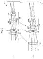
- FIG. 2 is a diagram showing zoom trajectories of respective lens groups of the zoom lens system according to Example 1 when the state of lens group positions varies from a wide-angle end state (W) to a telephoto end state (T).
- W wide-angle end state
- T telephoto end state
- FIG. 3 graphically shows various aberrations of the zoom lens system according to Example 1 in the wide-angle end state (W).
- FIG. 4 graphically shows various aberrations of the zoom lens system according to Example 1 in the telephoto end state (T).
- FIG. 5 is a diagram showing lens construction of a zoom lens system according to Example 2 of the present invention.
- FIG. 6 is a diagram showing zoom trajectories of respective lens groups of the zoom lens system according to Example 2 when the state of lens group positions varies from a wide-angle end state (W) to a telephoto end state (T).
- W wide-angle end state
- T telephoto end state
- FIG. 7 graphically shows various aberrations of the zoom lens system according to Example 2 in the wide-angle end state (W).
- FIG. 8 graphically shows various aberrations of the zoom lens system according to Example 2 in the telephoto end state (T).
- FIG. 9 is a diagram showing lens construction of a zoom lens system according to Example 3 of the present invention.
- FIG. 10 is a diagram showing zoom trajectories of respective lens groups of the zoom lens system according to Example 3 when the state of lens group positions varies from a wide-angle end state (W) to a telephoto end state (T).
- W wide-angle end state
- T telephoto end state
- FIG. 11 graphically shows various aberrations of the zoom lens system according to Example 3 in the wide-angle end state (W).
- FIG. 12 graphically shows various aberrations of the zoom lens system according to Example 3 in the telephoto end state (T).
- FIGS. 13A and 13B are schematic drawings showing an example of a Fresnel zone plate in which FIG. 13A is a plan view and FIG. 13B a sectional view sectioned by B—B plane in FIG. 13A .
- a characteristic of a multi-group type zoom lens system is explained as a generalization. Since at least two lens groups are necessary for construct a zoom lens system, the multi-group type zoom lens system is assumed to have a lens construction with three lens groups or more.
- a high zoom ratio can be accomplished by the increasing number of the lens groups that bear zooming. Since it is easy to average burdens of correcting aberrations of each lens group, it is possible to accomplish superb optical performance. However, when the number of lens groups moving along the optical axis increases, the mechanism of the lens barrel becomes complicate to be liable to increase the manufacturing cost.
- a three-group type zoom lens system having, in order from the object, a first lens group having positive refractive power, a second lens group having negative refractive power, and a third lens group having positive refractive power is applied.
- a diffractive optical surface is an optical surface that shows diffraction.
- a diffractive optical element is an optical element having a diffractive optical surface such as a conventionally well known Fresnel zone plate or a diffraction grating. Such diffractive optical element has been known to show a behavior different from refraction or reflection. In particular, it has negative dispersion.
- a diffractive optical element is arranged in a front lens group having positive refractive power locating to the object side of the largest air space in the third lens group so as to obtain superb optical performance by its effect.
- the diffractive optical surface is created by forming a diffraction grating on a surface of an optical element made of a glass or a resin material, or a surface generating diffraction effect by deflecting light such as Fresnel zone plate.
- FIGS. 13A and 13B are schematic drawings showing an example of a Fresnel zone plate in which FIG. 13A is a plan view and FIG. 13B a sectional view sectioned by B—B plane in FIG.
- the Fresnel zone plate 1 shown in FIG. 13 is a Kinoform type whose pitch is a continuous curve forming a grating groove of a diffractive optical element
- the periodical structure may be a stepwise shape, or a diagonal shape.
- the incident angle to the diffractive optical element is as small as possible. This is because when the incident angle of the light becomes large, flare light tends to be produced at the diffractive optical surface, so that it deteriorates optical performance. In order to obtain preferable optical performance not much being affected by the flare produced by the diffractive optical element, it is preferable for the present optical system that the incident angle is 10 degrees or less.
- the diffractive optical element locates any place as long as the condition satisfied, in the zoom lens system according to the present invention, it is preferable that the diffractive optical element is arranged in the front lens group in the third lens group. In order to sufficiently obtain the effect, it is preferable that the incident angle is seven degrees or less. It is further preferable that the incident angle in the telephoto end state is five degrees or less, and that in the wide-angle end state is six degrees or less.
- a zoom lens system according to the present invention is explained below with reference to conditional expressions (1) through (5).
- a zoom lens system according to the present invention is satisfied the following conditional expression (1): 0.3 ⁇ R/fw ⁇ 5.0 (1) where R denotes the radius of curvature of the object side surface of the positive lens locating to the image side of an aperture stop S in the third lens group, and fw denotes the focal length of the zoom lens system in the wide-angle end state.
- Conditional expression (1) defines the radius of curvature R of the object side surface of the positive lens locating to the image side of an aperture stop in the third lens group.
- the front lens group tends to be arranged in the vicinity of the aperture stop S.
- the lens shape composing the front lens group greatly relates to correcting spherical aberration and coma.
- the positive lens locating to the image side of the aperture stop (in the third lens group) is very important to preferably maintain aberration balance. It is desirable that the convex surface of it is facing to the object. Accordingly, in order to preferably balance aberrations, an appropriate range of the radius of curvature R of the object side surface of the positive lens is defined by the ratio to the focal length of the zoom lens system in the wide-angle end state. Here, R>0.
- the ratio R/fw When the ratio R/fw is equal to or exceeds the upper limit of conditional expression (1), the value of the radius of curvature R becomes too large, and spherical aberration becomes too large in the positive direction, so that preferable optical performance can no longer obtained.
- the ratio R/fw is equal to or falls below the lower limit of conditional expression (1), the value of the radius of curvature R becomes too small, and spherical aberration becomes too large in the negative direction, so that preferable optical performance can no longer obtained.
- a diffractive optical surface is arranged on any lens surface touching the air in the front lens group, and the following conditional expression (2) is preferably satisfied: 0.05 ⁇ L/f 3 ⁇ 1.0 (2) where L denotes the thickness of the lens element having the diffractive optical surface (the combined thickness when the surface is on the cemented lens), and f 3 denotes the focal length of the third lens group.
- Conditional expression (2) defines an appropriate range of the ratio of the thickness L of the lens element having the diffractive optical surface (the combined thickness when the surface is on the cemented lens) to the focal length of the third lens group f 3 .
- a diffractive optical surface is arrange on (any lens surface touching the air in the third lens group in) the zoom lens system to affect as an achromatic element
- the thickness of the other lens elements such as a cemented lens arranged for correcting chromatic aberration can be thinned, so that the whole lens system can be compact, thinned, and lightweight.
- conditional expression (2) shows a condition to effectively arrange a diffractive optical element in the lens system according to the present invention.
- the ratio L/f 3 When the ratio L/f 3 is equal to or exceeds the upper limit of conditional expression (2), L becomes too large, and the diffractive optical element becomes too thick and large, so that it become difficult to manufacture and also increases manufacturing cost.
- the ratio L/f 3 when the ratio L/f 3 is equal to or falls below the lower limit of conditional expression (2), the diffractive optical element becomes too thin, so that it causes production problems such that the element tends to bend upon manufacturing. Moreover, it tends to be deformed upon assembling, so that it is in danger of causing degradation of optical performance.
- conditional expression (3) is preferably satisfied: 0.1 ⁇ C/fw ⁇ 3.0 (3) where C denotes an effective diameter of the diffractive optical surface, and fw denotes the focal length of the zoom lens system in the wide-angle end state.
- Conditional expression (3) defines an appropriate range of the effective diameter C of the diffractive optical surface.
- the ratio C/fw is equal to or exceeds the upper limit of conditional expression (3), the value C of the effective diameter of the diffractive optical surface becomes too large, so that it becomes difficult to manufacture resulting in increasing manufacturing cost.
- harmful light from outside tends to enter the diffractive optical surface, so that image quality tends to be deteriorated by flare and the like.
- the ratio C/fw is equal to or falls below the lower limit of conditional expression (3)
- the value C of the effective diameter of the diffractive optical surface becomes too small, the groove pitch of the diffractive optical surface tends to become small, so that it becomes difficult to manufacture the diffractive optical surface resulting in increasing manufacturing cost as well as deteriorating imaging quality by increasing flare from the diffraction grating of the diffractive optical surface.
- the front lens group of the third lens group has a cemented positive lens, and a diffractive optical surface is formed on the most image side surface of the cemented positive lens, and the following conditional expression (4) is preferably satisfied: 0.001 ⁇ P/fw ⁇ 0.05 (4) where P denotes the smallest groove pitch of the diffractive optical surface, and fw denotes the focal length of the zoom lens system in the wide-angle end state.
- Conditional expression (4) defines an appropriate range of the smallest groove pitch P of the diffraction grating of the diffractive optical surface.
- an angle of deviation at any ray height can be controlled by varying the groove pitch, so that a so-called “aspherical effect” can be obtained.
- the groove pitch represents local refractive power, and the local refractive power becomes large upon narrowing the groove pitch, so that dispersion of the angle of deviation of the light can be large.
- the ratio P/fw is equal to or exceeds the upper limit of conditional expression (4), the groove pitch becomes too large, so that correction ability of chromatic aberration becomes small and it becomes difficult to correct aberrations well.
- a camera shake is liable to happen causing deteriorating the imaging quality.
- a zoom lens system according to the present invention by using the diffractive optical element, an optical system with a simple construction is accomplished, so that not only the lens barrel but also the camera on which the lens is equipped can be compact and lightweight.
- a vibration reduction mechanism can be stored in the space that is generated by miniaturizing the lens barrel.
- the weight reduced by the miniaturization can be allocated to the vibration reduction mechanism, so that an optical system with a superb vibration reduction mechanism can be provided.
- a practical vibration reduction lens system can be constructed by applying method such that the second lens group G 2 or a portion of the second lens group is moved (shifted) in the direction substantially perpendicular to the optical axis so as to correct a shooting image movement upon applying a vibration to the optical system.
- a shift amount of the whole lens system from the optical axis caused by vibration of the zoom lens system such as a camera shake is corrected by shifting an imaging position by means of shifting a lens group or a portion of lens group in the zoom lens system substantially perpendicularly to the optical axis by a suitable amount.
- conditional expression (5) is preferably satisfied: ⁇ S/fw ⁇ 0.1 (5) where ⁇ S denotes the maximum shift amount among the second lens group G 2 moved upon vibration reduction, and fw denotes the focal length of the zoom lens system in the wide-angle end state.
- Conditional expression (5) defines an appropriate rage of a ratio of the maximum shift amount ⁇ S (the amount of the maximum shift in the direction substantially perpendicular to the optical axis) among the second lens group G 2 moved upon vibration reduction to the focal length fw of the zoom lens system in the wide-angle end state.
- the vibration reduction lens group although either the whole second lens group or a portion of the second lens group may be used, when a portion of the second lens group constructed by lenses having a small effective diameter, it is more effective for miniaturizing the vibration reduction mechanism.
- refractive power of the vibration reduction lens group Gv is negative, either negative or positive refractive power can be set.
- the maximum shift amount ⁇ S of the second lens group becomes too large, so that variation in aberration upon vibration reduction becomes too large, so it is undesirable.
- the difference in the direction of the optical axis between the best image plane in meridional direction and that in sagittal direction becomes wide, and production of lateral chromatic aberration and decentered coma is large, so that it is undesirable.
- the vibration reduction lens group Gv does not shift at all, vibration reduction effect cannot be obtained, so that in conditional expression (5), ⁇ S>0.
- a vibration reduction lens system can be constructed by combining a vibration detector that detects vibration in the shooting lens, a vibration controller that sets a proper amount of vibration correction on the basis of a signal from a controller that controls an operation sequence of a camera and a signal from the vibration detector.
- At least one of the following conditional expressions (6) and (7) is preferably satisfied: 0.15 ⁇ N (6) ⁇ 1.0 ⁇ f 3 F/f 3 R ⁇ 0.05 (7)
- ⁇ N denotes a difference in refractive index at d-line between a positive lens and a negative lens composing the cemented lens (the most object side cemented lens when a plurality of cemented lenses are there) having a diffractive optical surface arranged in the third lens group
- f 3 F denotes the focal length of the front lens group in the third lens group
- f 3 R denotes the focal length of the rear lens group in the third lens group.
- the position of an on-axis ray passing a lens group in the vicinity of the aperture stop S tends to pass largely away from the optical axis, so that aberration correction of the on-axis ray is difficult.
- a diffractive optical surface is arranged in a front lens group in the third lens group, by properly setting in an appropriate range the difference in refractive index ⁇ N at d-line between a positive lens and a negative lens composing the cemented lens locating in the front lens group as shown in conditional expression (6), it is found to be possible to preferably correct the aforementioned on-axis chromatic aberration.
- refractive index of the positive lens is preferably lower than that of the negative lens.
- ⁇ N is equal to or falls below the lower limit of conditional expression (6), it becomes difficult to correct spherical aberration, so that preferable optical performance cannot be obtained.
- Petzval sum tends to become negative, so it is undesirable.
- Conditional expression (7) defines an appropriate range of the ratio of the focal length of the front lens group f 3 F to that of the rear lens group f 3 R in the third lens group.
- the ratio f 3 F/f 3 R is equal to or falls below the lower limit of conditional expression (7), the amount of the focal length of the rear lens group f 3 R becomes relatively too small, so that variation in coma upon zooming becomes large and distortion in the telephoto end state shifts largely in the negative direction, so it is undesirable.
- the ratio f 3 F/f 3 R is equal to or exceeds the upper limit of conditional expression (7)
- the amount of the focal length of the front lens group f 3 F becomes relatively too small, so that variation in spherical aberration upon zooming becomes large, so it is undesirable.
- spherical aberration in the telephoto end state becomes too large in the negative direction, so that preferable optical performance cannot be obtained.
- lower coma in the wide-angle end state produces in the negative direction and spherical aberration in the telephoto end state becomes over corrected in the negative direction, so that preferable optical performance cannot be obtained.
- the constituents sowing blow are further preferably satisfied.
- the first lens group consists only of a cemented lens constructed by a negative meniscus lens cemented with a double convex positive lens, or additionally includes a positive meniscus lens locating to the image side of the cemented lens.
- the first lens group consists only of the cemented lens.
- the second lens group preferably has a cemented lens.
- the cemented lens is preferably constructed by, in order from the object, a positive meniscus lens cemented with a double concave negative lens. With this construction, it is effective to suppress spherical aberration and curvature of field upon zooming.
- the using magnification of the second lens group varies intervening a unit magnification ( ⁇ 1) upon zooming from the wide-angle end state to the telephoto end state.
- the second lens group may be fixed upon zooming.
- effect of manufacturing error upon assembling can be small, so that it is preferable for the production engineering.
- the third lens group preferably has a cemented lens constructed by a positive lens and a negative lens.
- a diffractive optical surface is preferably formed on the most image side surface, which is the interface between the air and glass, of the cemented lens. This means that when the diffractive optical surface is formed on the cemented surface, the height of the diffraction grating becomes large, so that flare tends to be produced. It is preferable that the diffractive optical surface has positive refractive power.
- the angle of the principal ray for the maximum image height passing through the diffractive optical element is seven degrees or less.
- the diffractive optical surface in the vicinity of an aperture stop, the principal ray hardly tends to be affected deflection by diffraction, so that the color drift on the periphery of the image caused by diffraction can be reduced, so it is desirable.
- the third lens group is preferably composed of a front lens group having positive refractive power locating to the object side and a rear lens group having negative refractive power locating to the image side.
- the front lens group preferably has, in order from the object, a double convex lens, a cemented positive lens, and a positive meniscus lens.
- the rear lens group preferably has, in order from the object, a negative meniscus lens, a double convex lens, and a double concave lens.
- the air separation between the double convex lens and the double concave lens in the rear lens group is shortened as much as possible, it is effective for shortening the total lens length.
- the air separation is preferably smaller than the thickness of the double convex lens.
- focusing at a close object may be carried out by a so-called “front-focusing method” that is carried out by moving a first lens group forward.
- focusing may be carried out by a so-called “internal-focusing method” that is carried out by moving a third lens group or a portion of the third lens group along the optical axis.
- the diffractive optical surface When a diffractive optical surface is actually formed on a lens surface, in order to make it easy to fabricate, the diffractive optical surface preferably has a rotational symmetrical structure (grating structure) relative to the optical axis such as a Fresnel zone plate.
- the diffractive optical surface can be fabricated by means of fine grinding or glass molding as same as an ordinary aspherical lens.
- the diffractive optical surface may also be fabricated such that a thin resin layer is formed on a lens surface and a grating structure is formed on the resin layer.
- the diffraction grating is not limited to a simple single-layer structure such as a Kinoform, but is possible to use a multi-layer structure superposing a plurality of grating structures.
- a multi-structure diffraction grating is used, spectral characteristics and angular characteristics of diffraction efficiency can further be improved, so that it is convenient.
- the groove pitch preferably decreases monotonously from the center to the periphery.
- the diffractive optical surface is preferably made of an optical glass material having Abbe number of 65 or less. This is because forming a diffraction grating is easy and good optical performance can be obtained.
- a zoom lens system according to the present invention by using an aspherical lens or a graded-index lens in addition to each lens element composing the zoom lens system according to the present invention, it is needless to say that further preferable optical performance can obtained.
- the diffractive optical surface has positive refractive power and is preferably located to the image side of a negative lens cemented with a double convex lens arranged in the front lens group.
- the diffractive optical surface has positive refractive power
- the radius of curvature of the cemented surface can be large, so that it is effective to shorten the total length of the cemented lens and fabrication of the diffractive optical surface becomes easy, so it is convenient.
- high order chromatic aberration hardly produces and it is also convenient for correcting aberrations.
- respective zoom lens systems according to the present invention as shown in FIGS. 1 , 5 , and 9 include, in order from an object, a first lens group G 1 having positive refractive power, a second lens group G 2 having negative refractive power, a third lens group G 3 having positive refractive power.
- a distance between the first lens group G 1 and the second lens group G 2 varies, and a distance between the second lens group G 2 and the third lens group G 3 varies.
- the third lens group G 3 is composed of a front lens group having positive refractive power locating to the object side of the largest air space in the third lens group and a rear lens group having negative refractive power locating to the image side of the air space.
- the image plane is denoted by a reference symbol “I” in respective figures.
- the phase difference is calculated by means of an ordinary refractive index and an ultra-high index method that uses aspherical expressions (8) and (9) mentioned later.
- the ultra-high index method uses definite equivalence between the aspherical expression and the grating pitch of the diffractive optical surface.
- the diffractive optical surface is represented as data of the ultra-high index method, in other words, coefficients of aspherical expressions (8) and (9).
- aberration calculation is carried out at d-line, and g-line.
- the wavelength and the particular value of refractive index set relative to each spectral line, d-line, and g-line are shown in Table 1.
- an aspherical surface is represented by the following expressions (8) and (9):
- S ( y ) ( y 2 /r )/(1+(1 ⁇ y 2 /r 2 ) 1/2 )+ C 2 y 2 +C 4 y 4 +C 6 y 6 +C 8 y 8 +C 10 y 10 (8)
- R 1/((1 /r )+2 C 2 ) (9)
- y denotes ray height (incident height) perpendicular to the optical axis
- S(y) denotes sag amount that is the distance along the optical axis between tangent plane at the vertex of the aspherical surface and the aspherical surface at height y
- r denotes a reference radius of curvature
- R denotes a paraxial radius of curvature
- ⁇ denotes the conical coefficient
- C 2 denotes the second order aspherical coefficient
- C 4 denotes the 4th order asp
- an aspherical surface is shown by attaching an asterisk mark “*” to the right of surface number.
- the phase difference is calculated by means of an ordinary refractive index and an ultra-high index method that uses aspherical expressions (8) and (9). Accordingly, although aspherical expressions (8) and (9) are used for both aspherical surface and diffractive optical surface, aspherical expressions (8) and (9) used for an aspherical surface show the shape of the aspherical surface. On the other hand, aspherical expressions (8) and (9) used for a diffractive optical surface show various effects of the diffractive optical surface.
- FIG. 1 is a diagram showing lens construction of a zoom lens system according to Example 1 of the present invention.
- a first lens group G 1 having positive refractive power is composed of, in order from an object, a cemented lens constructed by a negative meniscus lens L 1 having a convex surface facing to the object cemented with a double convex lens L 2 .
- a second lens group G 2 having negative refractive power is composed of, in order from the object, a cemented lens constructed by a positive meniscus lens L 3 having a convex surface facing to an image cemented with a double concave lens L 4 and a double concave lens L 5 .
- a third lens group G 3 having positive refractive power is composed of, in order from the object, a double convex lens L 6 , an aperture stop S, a cemented lens constructed by a double convex lens L 7 cemented with a double concave lens L 8 having an aspherical surface forming on the image side surface, a positive meniscus lens L 9 having a convex surface facing to the object, a cemented lens constructed by a negative meniscus lens L 10 having a convex surface facing to the object cemented with a double convex lens L 11 , and a double concave lens L 12 .
- the third lens group G 3 is composed of a front lens group G 3 F having positive refractive power locating to the object side and a rear lens group G 3 R having negative refractive power locating to the image side.
- the front lens group G 3 F is composed of, in order from the object, a double convex lens L 6 , an aperture stop S, a cemented lens constructed by a double convex lens L 7 cemented with a double concave lens L 8 having an aspherical surface forming on the image side surface, and a positive meniscus lens L 9 having a convex surface facing to the object.
- the rear lens group G 3 R is composed of, in order from the object, a cemented lens constructed by a negative meniscus lens L 10 having a convex surface facing to the object cemented with a double convex lens L 11 , and a double concave lens L 12 .
- FIG. 2 is a diagram showing zoom trajectories of respective lens groups of the zoom lens system ZL 1 according to Example 1 when the state of lens group positions varies from a wide-angle end state (W) to a telephoto end state (T).
- W wide-angle end state
- T telephoto end state
- the second lens group G 2 that is a vibration reduction lens group Gv is moved in the direction perpendicular to the optical axis upon vibration reduction.
- Example 1 of the present invention Various values associated with Example 1 of the present invention are listed in Table 2 (unit associated with the length is mm).
- Table 2 the left most column of [Lens Data] is surface number.
- r denotes a radius of curvature of a lens surface (a radius of curvature of at the vertex in the case of an aspherical surface)
- d denotes a distance to the next lens surface
- nd denotes refractive index at d-line
- ng denotes refractive index at g-line.
- f denotes the focal length of the zoom lens system
- FNO denotes f-number.
- Example 1 surface distance d 3 (in other words, a distance between surface number 3 and surface number 4) shown in surface number 3 and surface distance d 8 (in other words, a distance between surface number 8 and surface number 9) vary upon zooming.
- surface number 11 is an aperture stop S.
- Surface numbers 14 and 15 corresponds to diffractive optical surfaces Gf. Various values associated with the diffractive optical surfaces Gf are shown by using the aforementioned ultra-high index method.
- Example 1 all conditional expressions (1) through (7) are satisfied.
- the amount of image shift corresponding to the moving amount of the vibration reduction lens group Gv of +0.5 is ⁇ 0.98861 (d-line) in the wide-angle end state and ⁇ 2.11920 (d-line) in the telephoto end state.
- the sign of the amount of image shift and that of the moving amount of the vibration reduction lens group Gv are the same, the moving direction of the vibration reduction lens group Gv and the shifting direction of the image are the same.
- these signs are different, the moving direction of the vibration reduction lens group Gv and the shifting direction of the image are different.
- the above-described explanation regarding sign in the vibration reduction lens group Gv is the same in the other Examples.
- FIG. 3 graphically shows various aberrations of the zoom lens system according to Example 1 in the wide-angle end state (W).
- FIG. 4 graphically shows various aberrations of the zoom lens system according to Example 1 in the telephoto end state (T).
- “d” denotes d-line
- “g” denotes g-line.
- FNO denotes f-number with respect to the maximum aperture.
- Y denotes the maximum image height.
- Y denotes each image height.
- a solid line indicates a sagittal image plane and a broken line indicates a meridional image plane.
- the explanation regarding aberration graphs is the same in the following Examples.
- the zoom lens according to Example 1 shows superb optical performance as a result of good corrections to various aberrations as a whole in each focal length state from the wide-angle end state to the telephoto end state.
- FIG. 5 is a diagram showing lens construction of a zoom lens system according to Example 2 of the present invention.
- a first lens group G 1 having positive refractive power is composed of, in order from an object, a cemented lens constructed by a negative meniscus lens L 1 having a convex surface facing to the object cemented with a double convex lens L 2 and a negative meniscus lens L 3 having a convex surface facing to the object.
- a second lens group G 2 having negative refractive power is composed of, in order from the object, a cemented lens constructed by a positive meniscus lens L 4 having a convex surface facing to an image cemented with a double concave lens L 5 and a double concave lens L 6 .
- a third lens group G 3 having positive refractive power is composed of, in order from the object, a double convex lens L 7 , an aperture stop S, a cemented lens constructed by a double convex lens L 8 cemented with a double concave lens L 9 having an aspherical surface forming on the image side surface, a positive meniscus lens L 10 having a convex surface facing to the object, a cemented lens constructed by a negative meniscus lens L 11 having a convex surface facing to the object cemented with a double convex lens L 12 , and a double concave lens L 13 .
- the third lens group G 3 is composed of a front lens group G 3 F having positive refractive power locating to the object side and a rear lens group G 3 R having negative refractive power locating to the image side.
- the front lens group G 3 F is composed of, in order from the object, a double convex lens L 7 , an aperture stop S, a cemented lens constructed by a double convex lens L 8 cemented with a double concave lens L 9 having an aspherical surface forming on the image side surface, and a positive meniscus lens L 10 having a convex surface facing to the object.
- the rear lens group G 3 R is composed of, in order from the object, a cemented lens constructed by a negative meniscus lens L 11 having a convex surface facing to the object cemented with a double convex lens L 12 , and a double concave lens L 13 .
- FIG. 6 is a diagram showing zoom trajectories of respective lens groups of the zoom lens system ZL 2 according to Example 2 when the state of lens group positions varies from a wide-angle end state (W) to a telephoto end state (T).
- W wide-angle end state
- T telephoto end state
- the second lens group G 2 that is a vibration reduction lens group Gv is moved in the direction perpendicular to the optical axis upon vibration reduction.
- Example 2 Various values associated with Example 2 of the present invention are listed in Table 3.
- surface distance d 5 (in other words, a distance between surface number 5 and surface number 6) shown in surface number 5 and surface distance d 10 (in other words, a distance between surface number 10 and surface number 11) vary upon zooming.
- surface number 13 is an aperture stop S.
- Surface numbers 16 and 17 corresponds to diffractive optical surfaces Gf.
- Various values associated with the diffractive optical surfaces Gf are shown by using the aforementioned ultra-high index method.
- Example 2 all conditional expressions (1) through (7) are satisfied.
- the amount of image shift corresponding to the moving amount of the vibration reduction lens group Gv of +0.5 is ⁇ 0.97941 (d-line) in the wide-angle end state and ⁇ 2.08865 (d-line) in the telephoto end state.
- FIG. 7 graphically shows various aberrations of the zoom lens system according to Example 2 in the wide-angle end state (W).
- FIG. 8 graphically shows various aberrations of the zoom lens system according to Example 2 in the telephoto end state (D.
- the zoom lens according to Example 2 shows superb optical performance as a result of good corrections to various aberrations as a whole in each focal length state from the wide-angle end state to the telephoto end state.
- FIG. 9 is a diagram showing lens construction of a zoom lens system according to Example 3 of the present invention.
- a first lens group G 1 having positive refractive power is composed of, in order from an object, a cemented lens constructed by a negative meniscus lens L 1 having a convex surface facing to the object cemented with a double convex lens L 2 .
- a second lens group G 2 having negative refractive power is composed of, in order from the object, a cemented lens constructed by a positive meniscus lens L 3 having a convex surface facing to an image cemented with a double concave lens L 4 and a double concave lens L 5 .
- a third lens group G 3 having positive refractive power is composed of, in order from the object, a double convex lens L 6 , an aperture stop S, a cemented lens constructed by a double convex lens L 7 cemented with a double concave lens L 8 having an aspherical surface forming on the image side surface, a positive meniscus lens L 9 having a convex surface facing to the object, a cemented lens constructed by a negative meniscus lens L 10 having a convex surface facing to the object cemented with a double convex lens L 11 , and a double concave lens L 12 .
- the third lens group G 3 is composed of a front lens group G 3 F having positive refractive power locating to the object side and a rear lens group G 3 R having negative refractive power locating to the image side.
- the front lens group G 3 F is composed of, in order from the object, a double convex lens L 6 , an aperture stop S, a cemented lens constructed by a double convex lens L 7 cemented with a double concave lens L 8 having an aspherical surface forming on the image side surface, and a positive meniscus lens L 9 having a convex surface facing to the object.
- the rear lens group G 3 R is composed of in order from the object, a cemented lens constructed by a negative meniscus lens L 10 having a convex surface facing to the object cemented with a double convex lens L 11 , and a double concave lens L 12 .
- FIG. 10 is a diagram showing zoom trajectories of respective lens groups of the zoom lens system ZL 3 according to Example 3 when the state of lens group positions varies from a wide-angle end state (W) to a telephoto end state M.
- W wide-angle end state
- M telephoto end state
- FIG. 10 it is shown that the second lens group G 2 that is a vibration reduction lens group Gv is moved in the direction perpendicular to the optical axis upon vibration reduction.
- Example 3 Various values associated with Example 3 of the present invention are listed in Table 4.
- surface distance d 3 in other words, a distance between surface number 3 and surface number 4
- surface distance d 8 in other words, a distance between surface number 8 and surface number 9
- surface number 11 is an aperture stop S.
- Surface numbers 14 and 15 corresponds to diffractive optical surfaces Gf
- Various values associated with the diffractive optical surfaces Gf are shown by using the aforementioned ultra-high index method.
- Example 3 all conditional expressions (1) through (7) are satisfied.
- the amount of image shift corresponding to the moving amount of the vibration reduction lens group Gv of +0.5 is ⁇ 0.97787 (d-line) in the wide-angle end state and ⁇ 2.16346 (d-line) in the telephoto end state.
- FIG. 11 graphically shows various aberrations of the zoom lens system according to Example 3 in the wide-angle end state (W).
- FIG. 12 graphically shows various aberrations of the zoom lens system according to Example 3 in the telephoto end state (T).
- the zoom lens according to Example 3 shows superb optical performance as a result of good corrections to various aberrations as a whole in each focal length state from the wide-angle end state to the telephoto end state.
- the present invention makes it possible to provide a zoom lens system having high optical performance with a diffractive optical element equipped with a vibration reduction mechanism suitable for a film camera, a video camera, a digital still camera, and the like.
Abstract
Description
0.3<R/fw<5.0 (1)
where R denotes a radius of curvature of the object side surface of a positive lens locating to the image side of the aperture stop and fw denotes the focal length of the zoom lens system in the wide-angle end state.
0.05<L/f3<1.0 (2)
where L denotes the thickness of the lens element having the diffractive optical surface (the combined thickness when the surface is on the cemented lens), and f3 denotes the focal length of the third lens group.
0.1<C/fw<3.0 (3)
where C denotes an effective diameter of the diffractive optical surface, and fw denotes the focal length of the zoom lens system in the wide-angle end state.
0.001<P/fw<0.05 (4)
where P denotes the smallest groove pitch of the diffractive optical surface, and fw denotes the focal length of the zoom lens system in the wide-angle end state.
ΔS/fw<0.1 (5)
where ΔS denotes the maximum shift amount among the second lens group moved upon vibration reduction, and fw denotes the focal length of the zoom lens system in the wide-angle end state.
0.3<R/fw<5.0 (1)
where R denotes the radius of curvature of the object side surface of the positive lens locating to the image side of an aperture stop S in the third lens group, and fw denotes the focal length of the zoom lens system in the wide-angle end state.
0.05<L/f3<1.0 (2)
where L denotes the thickness of the lens element having the diffractive optical surface (the combined thickness when the surface is on the cemented lens), and f3 denotes the focal length of the third lens group.
0.1<C/fw<3.0 (3)
where C denotes an effective diameter of the diffractive optical surface, and fw denotes the focal length of the zoom lens system in the wide-angle end state.
0.001<P/fw<0.05 (4)
where P denotes the smallest groove pitch of the diffractive optical surface, and fw denotes the focal length of the zoom lens system in the wide-angle end state.
ΔS/fw<0.1 (5)
where ΔS denotes the maximum shift amount among the second lens group G2 moved upon vibration reduction, and fw denotes the focal length of the zoom lens system in the wide-angle end state.
0.15<ΔN (6)
−1.0<f3F/f3R<−0.05 (7)
where ΔN denotes a difference in refractive index at d-line between a positive lens and a negative lens composing the cemented lens (the most object side cemented lens when a plurality of cemented lenses are there) having a diffractive optical surface arranged in the third lens group, f3F denotes the focal length of the front lens group in the third lens group, and f3R denotes the focal length of the rear lens group in the third lens group.
| TABLE 1 | ||||
| wave length | refractive index | |||
| d-line | 587.562 nm | 10001 | ||
| g-line | 435.835 nm | 7418.6853 | ||
S(y)=(y 2 /r)/(1+(1−κ·y 2 /r 2)1/2)+C 2 y 2 +C 4 y 4 +C 6 y 6 +C 8 y 8 +C 10 y 10 (8)
R=1/((1/r)+2C 2) (9)
where y denotes ray height (incident height) perpendicular to the optical axis, S(y) denotes sag amount that is the distance along the optical axis between tangent plane at the vertex of the aspherical surface and the aspherical surface at height y, r denotes a reference radius of curvature, R denotes a paraxial radius of curvature, κ denotes the conical coefficient, C2 denotes the second order aspherical coefficient, C4 denotes the 4th order aspherical coefficient, C6 denotes the 6th order aspherical coefficient, C8 denotes the 8th order aspherical coefficient, C10 denotes the 10th order aspherical coefficient.
| TABLE 2 |
| [Lens Data] |
| Surface | |||||
| Number | r | d | nd | ng | |
| 1 | 47.76982 | 1.40000 | 1.755200 | 1.791500 | L1 |
| 2 | 32.50521 | 7.04573 | 1.516330 | 1.526210 | L2 |
| 3 | −271.12620 | d3 | 1.000000 | ||
| 4 | −157.80021 | 2.96408 | 1.846660 | 1.894190 | L3 |
| 5 | −26.46083 | 1.20000 | 1.696800 | 1.712340 | L4 |
| 6 | 64.36653 | 2.18329 | 1.000000 | ||
| 7 | −31.31715 | 1.20000 | 1.772500 | 1.791970 | L5 |
| 8 | 205.51186 | d8 | 1.000000 | ||
| 9 | 60.09702 | 4.70821 | 1.497000 | 1.504510 | L6 |
| 10 | −45.92341 | 0.80000 | 1.000000 | ||
| 11 | Aperture | 1.00000 | 1.000000 | ||
| Stop S | |||||
| 12 | 79.82689 | 5.81750 | 1.603001 | 1.614372 | L7 |
| 13 | −23.88946 | 1.20000 | 1.803840 | 1.834635 | L8 |
| 14 | 135.00000 | 0.00000 | 10001 | 7418.68530 | |
| 15* | 135.00000 | 0.10000 | 1.000000 | ||
| 16 | 20.17320 | 4.36498 | 1.603001 | 1.614372 | L9 |
| 17 | 74.08164 | 11.31532 | 1.000000 | ||
| 18 | 24.52280 | 2.30769 | 1.804109 | 1.825809 | L10 |
| 19 | 11.12758 | 5.45740 | 1.603420 | 1.623810 | L11 |
| 20 | −36.77551 | 1.76134 | 1.000000 | ||
| 21 | −16.78364 | 2.00000 | 1.748099 | 1.765893 | L12 |
| 22 | 92.83962 | 38.63960 | 1.000000 | ||
| [Aspherical Data] |
| Surface Number 15 |
| κ = 1.0000 | ||
| C2 = −3.50000 × 10⁻⁹ | ||
| C4 = −8.42820 × 10⁻¹² | ||
| C6 = −7.59890 × 10⁻¹⁴ | ||
| C8 = −1.17000 × 10⁻¹⁵ | ||
| C10 = 5.92230 × 10⁻¹⁸ | ||
| [Variable Distances upon Zooming] |
| wide-angle | telephoto | |||
| end state (W) | end state (T) | |||
| f | 56.10 | 194.00 | ||
| FNO | 3.77 | 5.65 | ||
| d3 | 2.69845 | 35.06858 | ||
| d8 | 20.72462 | 1.41745 | ||
| [Values for Conditional Expressions] |
| R = 79.82689 | ||
| fw = 56.10000 | ||
| L = 7.0175 | ||
| f3 = 26.75764 | ||
| C = 21.47 | ||
| P = 247μ | ||
| ΔS = 0.5 | ||
| f3F = 30.43673 | ||
| f3R = −68.79975 | ||
| (1) R/fw = 1.422941 | ||
| (2) L/f3 = 0.262262 | ||
| (3) C/fw = 0.382709 | ||
| (4) P/fw = 0.004403 | ||
| (5) ΔS/fw = 0.008913 | ||
| (6) ΔN = 0.200839 | ||
| (7) f3F/f3R = −0.442396 | ||
| [Incident Angle of Principal Ray at Diffractive Optical Surface] |
| wide-angle | telephoto | ||
| end state (W) | end state (T) | ||
| 5.79° | 4.16° | ||
| TABLE 3 |
| [Lens Data] |
| Surface | |||||
| Number | r | d | nd | ng | |
| 1 | 53.74734 | 1.40000 | 1.756920 | 1.788014 | L1 |
| 2 | 32.60723 | 7.51878 | 1.516800 | 1.526703 | L2 |
| 3 | −151.34076 | 0.10000 | 1.000000 | ||
| 4 | 84.50000 | 2.00000 | 1.516800 | 1.526703 | L3 |
| 5 | 88.00000 | d5 | 1.000000 | ||
| 6 | −88.81223 | 2.87459 | 1.846660 | 1.894150 | L4 |
| 7 | −25.54935 | 1.20000 | 1.696800 | 1.712319 | L5 |
| 8 | 60.20040 | 2.22689 | 1.000000 | ||
| 9 | −33.85493 | 1.20000 | 1.748099 | 1.765893 | L6 |
| 10 | 3205.27995 | d10 | 1.000000 | ||
| 11 | 49.62686 | 4.30672 | 1.518601 | 1.527667 | L7 |
| 12 | −74.99845 | 0.80000 | 1.000000 | ||
| 13 | Aperture | 1.00000 | 1.000000 | ||
| Stop S | |||||
| 14 | 65.01156 | 5.82118 | 1.603001 | 1.614372 | L8 |
| 15 | −23.76273 | 1.20000 | 1.803840 | 1.834635 | L9 |
| 16 | 149.99989 | 0.00000 | 10001 | 7418.68530 | |
| 17* | 150.00016 | 0.10000 | 1.000000 | ||
| 18 | 20.58525 | 4.55222 | 1.603001 | 1.614372 | L10 |
| 19 | 81.42333 | 12.09084 | 1.000000 | ||
| 20 | 27.75124 | 0.90446 | 1.804109 | 1.825809 | L11 |
| 21 | 11.81096 | 5.58386 | 1.603420 | 1.623810 | L12 |
| 22 | −37.34213 | 2.32884 | 1.000000 | ||
| 23 | −15.85966 | 1.22709 | 1.748099 | 1.765893 | L13 |
| 24 | 235.22793 | 38.50002 | 1.000000 | ||
| [Aspherical Data] |
| Surface Number 17 |
| κ = 1.0000 | ||
| C2 = 0.00000 | ||
| C4 = −9.47020 × 10⁻¹² | ||
| C6 = 2.99610 × 10⁻¹⁴ | ||
| C8 = −3.00200 × 10⁻¹⁵ | ||
| C10 = 1.18910 × 10⁻¹⁷ | ||
| [Variable Distances upon Zooming] |
| wide-angle | telephoto | |||
| end state (W) | end state (T) | |||
| f | 56.91 | 194.00 | ||
| FNO | 3.73 | 5.64 | ||
| d5 | 1.47621 | 33.33560 | ||
| d10 | 20.99175 | 0.71119 | ||
| [Values for Conditional Expressions] |
| R = 65.01156 | ||
| fw = 56.91133 | ||
| L = 7.02118 | ||
| f3 = 27.26234 | ||
| C = 22.09 | ||
| P = 170μ | ||
| ΔS = 0.5 | ||
| f3F = 29.95863 | ||
| f3R = −59.46041 | ||
| (1) R/fw = 1.142331 | ||
| (2) L/f3 = 0.257541 | ||
| (3) C/fw = 0.388148 | ||
| (4) P/fw = 0.002987 | ||
| (5) ΔS/fw = 0.008786 | ||
| (6) ΔN = 0.200839 | ||
| (7) f3F/f3R = −0.503842 | ||
| [Incident Angle of Principal Ray at Diffractive Optical Surface] |
| wide-angle | telephoto | ||
| end state (W) | end state (T) | ||
| 5.69° | 4.13° | ||
| TABLE 4 |
| [Lens Data] |
| Surface | |||||
| Number | r | d | nd | ng | |
| 1 | 51.02481 | 1.40000 | 1.756920 | 1.788014 | L1 |
| 2 | 31.48045 | 7.51878 | 1.516800 | 1.526703 | L2 |
| 3 | −152.65341 | d3 | 1.000000 | ||
| 4 | −88.08894 | 2.87459 | 1.846660 | 1.894150 | L3 |
| 5 | −24.67927 | 1.20000 | 1.696800 | 1.712319 | L4 |
| 6 | 69.33417 | 2.22689 | 1.000000 | ||
| 7 | −33.77560 | 1.20000 | 1.772789 | 1.792324 | L5 |
| 8 | 467.93979 | d8 | 1.000000 | ||
| 9 | 49.62686 | 4.30672 | 1.518601 | 1.527667 | L6 |
| 10 | −63.09478 | 0.80000 | 1.000000 | ||
| 11 | Aperture | 1.00000 | 1.000000 | ||
| Stop S | |||||
| 12 | 70.71528 | 5.82118 | 1.603001 | 1.614372 | L7 |
| 13 | −23.46641 | 1.20000 | 1.803840 | 1.834635 | L8 |
| 14 | 150.00000 | 0.00000 | 10001 | 7418.68530 | |
| 15* | 150.00000 | 0.10000 | 1.000000 | ||
| 16 | 20.55443 | 4.36333 | 1.603001 | 1.614372 | L9 |
| 17 | 77.58508 | 11.78884 | 1.000000 | ||
| 18 | 27.91540 | 1.20000 | 1.804109 | 1.825809 | L10 |
| 19 | 11.52770 | 5.28546 | 1.603420 | 1.623810 | L11 |
| 20 | −34.48360 | 2.21402 | 1.000000 | ||
| 21 | −16.26388 | 2.00000 | 1.748099 | 1.765893 | L12 |
| 22 | 153.58420 | 38.50002 | 1.000000 | ||
| [Aspherical Data] |
| Surface Number 15 |
| κ = 1.0000 | ||
| C2 = −6.14910 × 10⁻⁹ | ||
| C4 = −9.47020 × 10⁻¹² | ||
| C6 = −2.99610 × 10⁻¹⁴ | ||
| C8 = −3.00200 × 10⁻¹⁵ | ||
| C10 = −1.18910 × 10⁻¹⁷ | ||
| [Variable Distances upon Zooming] |
| wide-angle | telephoto | |||
| end state (W) | end state (T) | |||
| f | 55.00 | 194.00 | ||
| FNO | 3.72 | 5.65 | ||
| d5 | 1.57590 | 33.55799 | ||
| d10 | 21.50538 | 1.66215 | ||
| [Values for Conditional Expressions] |
| R = 70.71528 | ||
| fw = 55.00007 | ||
| L = 7.02118 | ||
| f3 = 27.17713 | ||
| C = 22.00 | ||
| P = 170μ | ||
| ΔS = 0.5 | ||
| f3F = 29.81403 | ||
| f3R = −60.23696 | ||
| (1) R/fw = 1.285731 | ||
| (2) L/f3 = 0.258349 | ||
| (3) C/fw = 0.399999 | ||
| (4) P/fw = 0.003091 | ||
| (5) ΔS/fw = 0.009091 | ||
| (6) ΔN = 0.200839 | ||
| (7) f3F/f3R = 0.494946 | ||
| [Incident Angle of Principal Ray at Diffractive Optical Surface] |
| wide-angle | telephoto | ||
| end state (W) | end state (T) | ||
| 5.71° | 3.99° | ||
Claims (26)
0.3<R/fw<5.0
0.05<L/f3<1.0
0.1<C/fw<3.0
0.001<P/fw<0.05
ΔS/fw<0.1
0.1<C/fw<3.0
0.001<P/fw<0.05
ΔS/fw<0.1
0.001<P/fw<0.05
ΔS/fw<0.1
ΔS/fw<0.1
ΔS/fw<0.1
0.1<C/fw<3.0
0.05<L/f3<1.0
0.001<P/fw<0.05
0.03<R/fw<5.0
0.05<L/f3<1.0
0.1<C/fw<3.0
0.001<P/fw<0.05
0.1<C/fw<3.0
0.05<L/f3<1.0
0.001<P/fw<0.05
Applications Claiming Priority (2)
| Application Number | Priority Date | Filing Date | Title |
|---|---|---|---|
| JP2003337261A JP4513049B2 (en) | 2003-09-29 | 2003-09-29 | Zoom lens |
| JP2003-337261 | 2003-09-29 |
Publications (2)
| Publication Number | Publication Date |
|---|---|
| US20050068637A1 US20050068637A1 (en) | 2005-03-31 |
| US7123422B2 true US7123422B2 (en) | 2006-10-17 |
Family
ID=34373268
Family Applications (1)
| Application Number | Title | Priority Date | Filing Date |
|---|---|---|---|
| US10/950,560 Active 2024-10-01 US7123422B2 (en) | 2003-09-29 | 2004-09-28 | Zoom lens system |
Country Status (3)
| Country | Link |
|---|---|
| US (1) | US7123422B2 (en) |
| JP (1) | JP4513049B2 (en) |
| CN (1) | CN100538428C (en) |
Cited By (8)
| Publication number | Priority date | Publication date | Assignee | Title |
|---|---|---|---|---|
| US20060245079A1 (en) * | 2005-03-30 | 2006-11-02 | Hiroshi Yamamoto | Zoom lens system |
| US20080112063A1 (en) * | 2006-11-14 | 2008-05-15 | Canon Kabushiki Kaisha | Zoom lens and image pickup apparatus having the same |
| US20090103186A1 (en) * | 2007-10-17 | 2009-04-23 | Masashi Hankawa | Zoom lens and image pickup apparatus equipped with same |
| US20110080565A1 (en) * | 2009-10-02 | 2011-04-07 | Canon Kabushiki Kaisha | Image projecting apparatus |
| CN101414050B (en) * | 2007-10-17 | 2012-12-05 | 奥林巴斯映像株式会社 | Zoom lens and image pickup apparatus equipped with same |
| US20130222925A1 (en) * | 2012-02-28 | 2013-08-29 | Pentax Ricoh Imaging Company, Ltd. | Close-distance correcting lens system |
| US20140204462A1 (en) * | 2011-04-06 | 2014-07-24 | Miho Matsumoto | Zoom optical system and imaging device having the same |
| US20150338605A1 (en) * | 2014-05-26 | 2015-11-26 | Olympus Corporation | Wide Angle Lens and Image Pickup Apparatus Using the Same |
Families Citing this family (22)
| Publication number | Priority date | Publication date | Assignee | Title |
|---|---|---|---|---|
| JP4548766B2 (en) * | 2003-11-14 | 2010-09-22 | 株式会社リコー | Zoom lens, lens unit, camera, and portable information terminal device |
| JP4708734B2 (en) * | 2004-05-28 | 2011-06-22 | キヤノン株式会社 | Zoom lens and imaging apparatus having the same |
| JP4585794B2 (en) * | 2004-05-31 | 2010-11-24 | キヤノン株式会社 | Zoom lens and imaging apparatus having the same |
| JP2007072132A (en) * | 2005-09-06 | 2007-03-22 | Fujifilm Corp | Soft-focus photographing system |
| JP4829590B2 (en) * | 2005-10-25 | 2011-12-07 | キヤノン株式会社 | Imaging optical system and imaging apparatus having the same |
| JP4921050B2 (en) * | 2006-06-19 | 2012-04-18 | キヤノン株式会社 | Zoom lens and imaging apparatus having the same |
| JP4898410B2 (en) * | 2006-12-14 | 2012-03-14 | キヤノン株式会社 | Zoom lens and imaging apparatus having the same |
| JP4305506B2 (en) * | 2006-12-15 | 2009-07-29 | カシオ計算機株式会社 | Lens system and projector apparatus using the same |
| JP5339784B2 (en) | 2008-06-03 | 2013-11-13 | キヤノン株式会社 | Zoom lens and imaging apparatus having the same |
| JP5272614B2 (en) * | 2008-09-26 | 2013-08-28 | 株式会社リコー | Wide angle lens and imaging apparatus using the wide angle lens |
| KR101495540B1 (en) | 2009-03-13 | 2015-02-25 | 삼성전자주식회사 | Telephoto lens system and photographing device having the same |
| KR101676785B1 (en) * | 2009-10-13 | 2016-11-16 | 삼성전자주식회사 | Compact zoom lens |
| JP5614448B2 (en) | 2010-06-16 | 2014-10-29 | 株式会社ニコン | Microscope objective lens |
| WO2012052805A1 (en) * | 2010-10-20 | 2012-04-26 | Nokia Corporation | Optical image stabilization |
| CN107942531A (en) * | 2010-12-17 | 2018-04-20 | 株式会社尼康 | Optical system |
| JP2013011641A (en) * | 2011-06-28 | 2013-01-17 | Sony Corp | Zoom lens and imaging apparatus |
| WO2013118480A1 (en) * | 2012-02-06 | 2013-08-15 | 富士フイルム株式会社 | Imaging lens and imaging device |
| JP6528355B2 (en) * | 2014-03-27 | 2019-06-12 | 株式会社ニコン | Variable magnification optical unit and imaging apparatus |
| CN110596873B (en) | 2014-03-27 | 2022-09-20 | 株式会社尼康 | Variable power optical system and imaging device |
| JP6602101B2 (en) * | 2015-08-21 | 2019-11-06 | キヤノン株式会社 | Zoom lens and imaging apparatus having the same |
| JP7341634B2 (en) * | 2017-09-20 | 2023-09-11 | 株式会社小糸製作所 | Vehicle lights |
| CN111025617B (en) * | 2019-12-24 | 2021-02-19 | 中国科学院福建物质结构研究所 | Laser microscope objective |
Citations (3)
| Publication number | Priority date | Publication date | Assignee | Title |
|---|---|---|---|---|
| JPH11305126A (en) | 1998-04-21 | 1999-11-05 | Minolta Co Ltd | Optical lens system |
| US6704149B2 (en) | 1998-04-21 | 2004-03-09 | Minolta Co., Ltd. | Lens optical system |
| JP2004258239A (en) * | 2003-02-25 | 2004-09-16 | Nikon Corp | Zoom lens |
Family Cites Families (6)
| Publication number | Priority date | Publication date | Assignee | Title |
|---|---|---|---|---|
| JPS63298210A (en) * | 1987-05-29 | 1988-12-06 | Sigma:Kk | Zoom lens |
| JPH0727977A (en) * | 1993-07-12 | 1995-01-31 | Nikon Corp | Zoom lens system with vibration-proof function |
| JPH0763993A (en) * | 1993-08-31 | 1995-03-10 | Nikon Corp | Telescopic zoom lens |
| JP2000221401A (en) * | 1999-02-03 | 2000-08-11 | Minolta Co Ltd | Lens optical system |
| JP2000267004A (en) * | 1999-03-12 | 2000-09-29 | Canon Inc | Zoom lens |
| JP3542552B2 (en) * | 2000-09-29 | 2004-07-14 | キヤノン株式会社 | Zoom lens and optical device using the same |
-
2003
- 2003-09-29 JP JP2003337261A patent/JP4513049B2/en not_active Expired - Fee Related
-
2004
- 2004-09-28 US US10/950,560 patent/US7123422B2/en active Active
- 2004-09-29 CN CNB2004100832038A patent/CN100538428C/en not_active Expired - Fee Related
Patent Citations (3)
| Publication number | Priority date | Publication date | Assignee | Title |
|---|---|---|---|---|
| JPH11305126A (en) | 1998-04-21 | 1999-11-05 | Minolta Co Ltd | Optical lens system |
| US6704149B2 (en) | 1998-04-21 | 2004-03-09 | Minolta Co., Ltd. | Lens optical system |
| JP2004258239A (en) * | 2003-02-25 | 2004-09-16 | Nikon Corp | Zoom lens |
Non-Patent Citations (1)
| Title |
|---|
| Introduction to Diffractive Optical Elements, Published by OPTRONICS, May 20, 1997, pp. 7-14, 30-35, and 117-125 (with English translation). |
Cited By (17)
| Publication number | Priority date | Publication date | Assignee | Title |
|---|---|---|---|---|
| US20060245079A1 (en) * | 2005-03-30 | 2006-11-02 | Hiroshi Yamamoto | Zoom lens system |
| US7274519B2 (en) * | 2005-03-30 | 2007-09-25 | Nikon Corporation | Zoom lens system |
| US20080112063A1 (en) * | 2006-11-14 | 2008-05-15 | Canon Kabushiki Kaisha | Zoom lens and image pickup apparatus having the same |
| US7471462B2 (en) | 2006-11-14 | 2008-12-30 | Canon Kabushiki Kaisha | Zoom lens and image pickup apparatus having the same |
| US8014078B2 (en) | 2007-10-17 | 2011-09-06 | Olympus Imaging Corp. | Zoom lens and image pickup apparatus equipped with same |
| US20100321546A1 (en) * | 2007-10-17 | 2010-12-23 | Masashi Hankawa | Zoom lens and image pickup apparatus equipped with same |
| US7944622B2 (en) * | 2007-10-17 | 2011-05-17 | Olympus Imaging Corp. | Zoom lens and image pickup apparatus equipped with same |
| US20090103186A1 (en) * | 2007-10-17 | 2009-04-23 | Masashi Hankawa | Zoom lens and image pickup apparatus equipped with same |
| CN101414050B (en) * | 2007-10-17 | 2012-12-05 | 奥林巴斯映像株式会社 | Zoom lens and image pickup apparatus equipped with same |
| US20110080565A1 (en) * | 2009-10-02 | 2011-04-07 | Canon Kabushiki Kaisha | Image projecting apparatus |
| US8573788B2 (en) * | 2009-10-02 | 2013-11-05 | Canon Kabushiki Kaisha | Image projecting apparatus having an optical element shiftable in a direction having a component perpendicular to an optical axis |
| US20140204462A1 (en) * | 2011-04-06 | 2014-07-24 | Miho Matsumoto | Zoom optical system and imaging device having the same |
| US9625733B2 (en) * | 2011-04-06 | 2017-04-18 | Nikon Corporation | Zoom optical system comprising diffractive optical element and imaging device having the same |
| US20130222925A1 (en) * | 2012-02-28 | 2013-08-29 | Pentax Ricoh Imaging Company, Ltd. | Close-distance correcting lens system |
| US9201219B2 (en) * | 2012-02-28 | 2015-12-01 | Ricoh Imaging Company, Ltd. | Close-distance correcting lens system |
| US20150338605A1 (en) * | 2014-05-26 | 2015-11-26 | Olympus Corporation | Wide Angle Lens and Image Pickup Apparatus Using the Same |
| US9753250B2 (en) * | 2014-05-26 | 2017-09-05 | Olympus Corporation | Wide angle lens and image pickup apparatus using the same |
Also Published As
| Publication number | Publication date |
|---|---|
| JP4513049B2 (en) | 2010-07-28 |
| CN1603876A (en) | 2005-04-06 |
| JP2005106925A (en) | 2005-04-21 |
| CN100538428C (en) | 2009-09-09 |
| US20050068637A1 (en) | 2005-03-31 |
Similar Documents
| Publication | Publication Date | Title |
|---|---|---|
| US7123422B2 (en) | Zoom lens system | |
| US8320051B2 (en) | Zoom lens system, imaging device and camera | |
| US7209299B2 (en) | Vibration reduction zoom lens system | |
| US7075734B2 (en) | Zoom lens system | |
| US7139130B2 (en) | Zoom lens, and optical apparatus using the same | |
| US7649699B2 (en) | Cemented lens and optical system having the same | |
| US10095012B2 (en) | Zoom lens system, optical apparatus and method for manufacturing zoom lens system | |
| US7561342B2 (en) | Zoom lens system | |
| US11294155B2 (en) | Variable magnification optical system, optical device, and method for manufacturing variable magnification optical system | |
| US20150153549A1 (en) | Zoom lens system, optical apparatus and method for manufacturing zoom lens system | |
| US20080117528A1 (en) | High magnification zoom lens | |
| US20120050886A1 (en) | Zoom lens, optical apparatus and zoom lens manufacturing method | |
| US6741398B2 (en) | Zoom lens system, image projecting and image pick-up devices using the same | |
| US6556356B2 (en) | Zoom lens system | |
| US7580201B2 (en) | Zoom lens system | |
| JPH06130298A (en) | Compact zoom lens | |
| JP5845886B2 (en) | Zoom lens and imaging device | |
| JP4470143B2 (en) | Zoom lens | |
| US11733499B2 (en) | Optical system, optical apparatus and method for manufacturing the optical system | |
| JP4470141B2 (en) | Zoom lens | |
| US7136226B2 (en) | Front teleconverter lens system | |
| US20150185495A1 (en) | Variable-magnification optical system, optical device having same variable-magnification optical system, and method for manufacturing variable-magnification optical system | |
| US8885265B2 (en) | Zoom lens system, imaging device and camera | |
| JP2004126397A (en) | Telephotographic lens | |
| JP4423587B2 (en) | Zoom lens |
Legal Events
| Date | Code | Title | Description |
|---|---|---|---|
| AS | Assignment |
Owner name: NIKON CORPORATION, JAPAN Free format text: ASSIGNMENT OF ASSIGNORS INTEREST;ASSIGNOR:SUZUKI, KENZABURO;REEL/FRAME:015845/0206 Effective date: 20040921 |
|
| STCF | Information on status: patent grant |
Free format text: PATENTED CASE |
|
| FEPP | Fee payment procedure |
Free format text: PAYOR NUMBER ASSIGNED (ORIGINAL EVENT CODE: ASPN); ENTITY STATUS OF PATENT OWNER: LARGE ENTITY Free format text: PAYER NUMBER DE-ASSIGNED (ORIGINAL EVENT CODE: RMPN); ENTITY STATUS OF PATENT OWNER: LARGE ENTITY |
|
| FPAY | Fee payment |
Year of fee payment: 4 |
|
| FPAY | Fee payment |
Year of fee payment: 8 |
|
| MAFP | Maintenance fee payment |
Free format text: PAYMENT OF MAINTENANCE FEE, 12TH YEAR, LARGE ENTITY (ORIGINAL EVENT CODE: M1553) Year of fee payment: 12 |