CN100501581C - Imaging device and method and recording medium determination device and method - Google Patents
Imaging device and method and recording medium determination device and method Download PDFInfo
- Publication number
- CN100501581C CN100501581C CNB2005100588353A CN200510058835A CN100501581C CN 100501581 C CN100501581 C CN 100501581C CN B2005100588353 A CNB2005100588353 A CN B2005100588353A CN 200510058835 A CN200510058835 A CN 200510058835A CN 100501581 C CN100501581 C CN 100501581C
- Authority
- CN
- China
- Prior art keywords
- recording medium
- image
- conveying
- read
- imaging
- Prior art date
- Legal status (The legal status is an assumption and is not a legal conclusion. Google has not performed a legal analysis and makes no representation as to the accuracy of the status listed.)
- Expired - Fee Related
Links
- 238000000034 method Methods 0.000 title claims abstract description 43
- 238000003384 imaging method Methods 0.000 title claims description 93
- 238000012546 transfer Methods 0.000 claims description 18
- 238000012545 processing Methods 0.000 claims description 10
- 238000004364 calculation method Methods 0.000 claims description 7
- 230000008030 elimination Effects 0.000 claims description 4
- 238000003379 elimination reaction Methods 0.000 claims description 4
- 230000015572 biosynthetic process Effects 0.000 claims description 3
- 238000007639 printing Methods 0.000 claims description 2
- 238000009877 rendering Methods 0.000 abstract 1
- 239000000463 material Substances 0.000 description 128
- 238000010586 diagram Methods 0.000 description 21
- 238000006073 displacement reaction Methods 0.000 description 16
- 238000001514 detection method Methods 0.000 description 10
- 230000003287 optical effect Effects 0.000 description 6
- 238000011161 development Methods 0.000 description 4
- 230000003760 hair shine Effects 0.000 description 3
- 241001269238 Data Species 0.000 description 2
- 238000006243 chemical reaction Methods 0.000 description 2
- 239000000428 dust Substances 0.000 description 2
- 238000005259 measurement Methods 0.000 description 2
- 230000035945 sensitivity Effects 0.000 description 2
- 230000001360 synchronised effect Effects 0.000 description 2
- 238000012935 Averaging Methods 0.000 description 1
- DGAQECJNVWCQMB-PUAWFVPOSA-M Ilexoside XXIX Chemical compound C[C@@H]1CC[C@@]2(CC[C@@]3(C(=CC[C@H]4[C@]3(CC[C@@H]5[C@@]4(CC[C@@H](C5(C)C)OS(=O)(=O)[O-])C)C)[C@@H]2[C@]1(C)O)C)C(=O)O[C@H]6[C@@H]([C@H]([C@@H]([C@H](O6)CO)O)O)O.[Na+] DGAQECJNVWCQMB-PUAWFVPOSA-M 0.000 description 1
- 230000003213 activating effect Effects 0.000 description 1
- 230000003321 amplification Effects 0.000 description 1
- 230000015556 catabolic process Effects 0.000 description 1
- 238000012937 correction Methods 0.000 description 1
- 238000006731 degradation reaction Methods 0.000 description 1
- 230000006866 deterioration Effects 0.000 description 1
- 238000005516 engineering process Methods 0.000 description 1
- 230000002349 favourable effect Effects 0.000 description 1
- 238000001914 filtration Methods 0.000 description 1
- 229910052736 halogen Inorganic materials 0.000 description 1
- 150000002367 halogens Chemical class 0.000 description 1
- 238000010438 heat treatment Methods 0.000 description 1
- 238000012423 maintenance Methods 0.000 description 1
- 238000012986 modification Methods 0.000 description 1
- 230000004048 modification Effects 0.000 description 1
- 238000003199 nucleic acid amplification method Methods 0.000 description 1
- 230000003252 repetitive effect Effects 0.000 description 1
- 238000005070 sampling Methods 0.000 description 1
- 238000004904 shortening Methods 0.000 description 1
- 238000004088 simulation Methods 0.000 description 1
- 229910052708 sodium Inorganic materials 0.000 description 1
- 239000011734 sodium Substances 0.000 description 1
- 230000003068 static effect Effects 0.000 description 1
- 238000010023 transfer printing Methods 0.000 description 1
- 230000000007 visual effect Effects 0.000 description 1
- 238000003466 welding Methods 0.000 description 1
- 229910052724 xenon Inorganic materials 0.000 description 1
- FHNFHKCVQCLJFQ-UHFFFAOYSA-N xenon atom Chemical compound [Xe] FHNFHKCVQCLJFQ-UHFFFAOYSA-N 0.000 description 1
Images


Classifications
-
- H—ELECTRICITY
- H04—ELECTRIC COMMUNICATION TECHNIQUE
- H04N—PICTORIAL COMMUNICATION, e.g. TELEVISION
- H04N1/00—Scanning, transmission or reproduction of documents or the like, e.g. facsimile transmission; Details thereof
- H04N1/00681—Detecting the presence, position or size of a sheet or correcting its position before scanning
- H04N1/00684—Object of the detection
- H04N1/00726—Other properties of the sheet, e.g. curvature or reflectivity
-
- G—PHYSICS
- G03—PHOTOGRAPHY; CINEMATOGRAPHY; ANALOGOUS TECHNIQUES USING WAVES OTHER THAN OPTICAL WAVES; ELECTROGRAPHY; HOLOGRAPHY
- G03G—ELECTROGRAPHY; ELECTROPHOTOGRAPHY; MAGNETOGRAPHY
- G03G15/00—Apparatus for electrographic processes using a charge pattern
-
- G—PHYSICS
- G03—PHOTOGRAPHY; CINEMATOGRAPHY; ANALOGOUS TECHNIQUES USING WAVES OTHER THAN OPTICAL WAVES; ELECTROGRAPHY; HOLOGRAPHY
- G03G—ELECTROGRAPHY; ELECTROPHOTOGRAPHY; MAGNETOGRAPHY
- G03G15/00—Apparatus for electrographic processes using a charge pattern
- G03G15/65—Apparatus which relate to the handling of copy material
- G03G15/6502—Supplying of sheet copy material; Cassettes therefor
- G03G15/6508—Automatic supply devices interacting with the rest of the apparatus, e.g. selection of a specific cassette
-
- G—PHYSICS
- G03—PHOTOGRAPHY; CINEMATOGRAPHY; ANALOGOUS TECHNIQUES USING WAVES OTHER THAN OPTICAL WAVES; ELECTROGRAPHY; HOLOGRAPHY
- G03G—ELECTROGRAPHY; ELECTROPHOTOGRAPHY; MAGNETOGRAPHY
- G03G15/00—Apparatus for electrographic processes using a charge pattern
- G03G15/65—Apparatus which relate to the handling of copy material
- G03G15/6588—Apparatus which relate to the handling of copy material characterised by the copy material, e.g. postcards, large copies, multi-layered materials, coloured sheet material
-
- H—ELECTRICITY
- H04—ELECTRIC COMMUNICATION TECHNIQUE
- H04N—PICTORIAL COMMUNICATION, e.g. TELEVISION
- H04N1/00—Scanning, transmission or reproduction of documents or the like, e.g. facsimile transmission; Details thereof
- H04N1/00002—Diagnosis, testing or measuring; Detecting, analysing or monitoring not otherwise provided for
- H04N1/00026—Methods therefor
- H04N1/00037—Detecting, i.e. determining the occurrence of a predetermined state
-
- H—ELECTRICITY
- H04—ELECTRIC COMMUNICATION TECHNIQUE
- H04N—PICTORIAL COMMUNICATION, e.g. TELEVISION
- H04N1/00—Scanning, transmission or reproduction of documents or the like, e.g. facsimile transmission; Details thereof
- H04N1/00002—Diagnosis, testing or measuring; Detecting, analysing or monitoring not otherwise provided for
- H04N1/00026—Methods therefor
- H04N1/0005—Methods therefor in service, i.e. during normal operation
-
- H—ELECTRICITY
- H04—ELECTRIC COMMUNICATION TECHNIQUE
- H04N—PICTORIAL COMMUNICATION, e.g. TELEVISION
- H04N1/00—Scanning, transmission or reproduction of documents or the like, e.g. facsimile transmission; Details thereof
- H04N1/00002—Diagnosis, testing or measuring; Detecting, analysing or monitoring not otherwise provided for
- H04N1/00071—Diagnosis, testing or measuring; Detecting, analysing or monitoring not otherwise provided for characterised by the action taken
- H04N1/00082—Adjusting or controlling
- H04N1/00087—Setting or calibrating
-
- H—ELECTRICITY
- H04—ELECTRIC COMMUNICATION TECHNIQUE
- H04N—PICTORIAL COMMUNICATION, e.g. TELEVISION
- H04N1/00—Scanning, transmission or reproduction of documents or the like, e.g. facsimile transmission; Details thereof
- H04N1/00002—Diagnosis, testing or measuring; Detecting, analysing or monitoring not otherwise provided for
- H04N1/00092—Diagnosis, testing or measuring; Detecting, analysing or monitoring not otherwise provided for relating to the original or to the reproducing medium, e.g. imperfections or dirt
-
- H—ELECTRICITY
- H04—ELECTRIC COMMUNICATION TECHNIQUE
- H04N—PICTORIAL COMMUNICATION, e.g. TELEVISION
- H04N1/00—Scanning, transmission or reproduction of documents or the like, e.g. facsimile transmission; Details thereof
- H04N1/23—Reproducing arrangements
- H04N1/2307—Circuits or arrangements for the control thereof, e.g. using a programmed control device, according to a measured quantity
- H04N1/2323—Circuits or arrangements for the control thereof, e.g. using a programmed control device, according to a measured quantity according to characteristics of the reproducing medium, e.g. type, size or availability
-
- H—ELECTRICITY
- H04—ELECTRIC COMMUNICATION TECHNIQUE
- H04N—PICTORIAL COMMUNICATION, e.g. TELEVISION
- H04N1/00—Scanning, transmission or reproduction of documents or the like, e.g. facsimile transmission; Details thereof
- H04N1/23—Reproducing arrangements
- H04N1/2307—Circuits or arrangements for the control thereof, e.g. using a programmed control device, according to a measured quantity
- H04N1/2369—Selecting a particular reproducing mode from amongst a plurality of modes, e.g. paper saving or normal, or simplex or duplex
-
- H—ELECTRICITY
- H04—ELECTRIC COMMUNICATION TECHNIQUE
- H04N—PICTORIAL COMMUNICATION, e.g. TELEVISION
- H04N1/00—Scanning, transmission or reproduction of documents or the like, e.g. facsimile transmission; Details thereof
- H04N1/23—Reproducing arrangements
- H04N1/29—Reproducing arrangements involving production of an electrostatic intermediate picture
- H04N1/295—Circuits or arrangements for the control thereof, e.g. using a programmed control device, according to a measured quantity
-
- G—PHYSICS
- G03—PHOTOGRAPHY; CINEMATOGRAPHY; ANALOGOUS TECHNIQUES USING WAVES OTHER THAN OPTICAL WAVES; ELECTROGRAPHY; HOLOGRAPHY
- G03G—ELECTROGRAPHY; ELECTROPHOTOGRAPHY; MAGNETOGRAPHY
- G03G2215/00—Apparatus for electrophotographic processes
- G03G2215/00362—Apparatus for electrophotographic processes relating to the copy medium handling
- G03G2215/00443—Copy medium
Landscapes
- Engineering & Computer Science (AREA)
- Multimedia (AREA)
- Signal Processing (AREA)
- Health & Medical Sciences (AREA)
- Biomedical Technology (AREA)
- General Health & Medical Sciences (AREA)
- Physics & Mathematics (AREA)
- General Physics & Mathematics (AREA)
- Control Or Security For Electrophotography (AREA)
- Laser Beam Printer (AREA)
- Facsimiles In General (AREA)
- Fax Reproducing Arrangements (AREA)
Abstract
It reduces a moving distance of a recording medium and thereby reduces the moving distance to be secured in an image forming apparatus so as to reduce size of the apparatus by a simple method. It is possible to feed a recording medium 304 at lower speed than normal speed on calibrating of a sensor unit 123 so as to reduce a distance passed by the recording medium 304. It is possible to render the moving distance of the recording medium half by rendering feeding speed on the calibrating half the normal speed.
Description
Technical field
The present invention relates to a kind of imaging device and method, particularly a kind of recording materials that are used for also definite its kind of reflected light of detection record material surface are determined apparatus and method, and a kind of imaging device and method of using these recording materials to determine device.
Background technology
Be transferred on the recording materials such as the imaging device of duplicating machine or the laser printer image development part is visual and that develop, then, under predetermined fixing conditions, to its heating and pressurization, with photographic fixing developer image.Predetermined fixing conditions is different and significantly different according to quality, thickness and the surface-treated of recording materials.Therefore, when using multiple recording materials, require to be provided with in detail according to the kind of recording materials.
In the past, this imaging device have the user by for example be arranged on imaging device originally on one's body guidance panel the size of recording materials and kind are set (if recording materials are paper, then be stationery), so that change fixing conditions (for example, the transporting velocity of fixing temperature and the recording materials by fixing device) to be set according to this.In addition, a kind of method has been proposed, this method makes control device with the temperature setting lower than normal temperature, and solves unfavorable problem, for example, make ink-jet OHT (transparency the user, but not the paper mistake of regulation OHT takes place on fixing roller twine when passing over headtransparency),, and the image degradation on the recording medium (for example, disclosing 2003-228256 number) referring to Jap.P..
Also has a kind of known method, it is not limited to OHT, it calculates the height and the particulate interval of the particulate on the recording medium surface, then by the surface image of reading ﹠ recording medium, determine the kind of recording medium, for example, machine-glazed paper, blank sheet of paper, toilet paper (roughpaper) or OHT are provided with image-forming condition with the best, transfer bias, fixing temperature and the processing speed (for example, please refer to 2003-302208 number and 2001-225988 number Japanese pending application) that comprise print density, foundation.
This image read-out great majority have the electrical image (shotimage) that degrades, because the light quantity that light source or lens cause changes.The sensitivity of the optical unit of camera head also changes.Because this reason in order accurately to read object and to obtain correct imaging results, can be imagined a kind of image pickup method, this image pickup method is under the state that makes the recording medium motion, repeatedly measures the shade amount, then, make its shooting results average, with automatic calculating shade amount and correcting captured result.
Yet,, need under the state that makes the recording medium motion, take repeatedly for above-mentioned imaging device.Because this reason, the problem of existence be, in this imaging device, must guarantee to be used to make enough areas of recording medium motion, therefore, this device becomes huge.
Summary of the invention
The present invention makes in view of these problems, and an one purpose is to improve conventional apparatus, so that a kind of accuracy that can keep determining recording medium to be provided, and does not increase the apparatus and method of plant bulk.Determine recording medium by the configuration of adopting image pickup device and lens, and be not subjected to because the influence of the detection skewness that light source, lens or image pickup device cause.In this respect, the object of the present invention is to provide a kind of imaging device and method, it is simple, keep required accuracy, and the size of aggrandizement apparatus not.
To achieve these goals, the invention provides a kind of imaging device, it is characterized in that comprising: imaging portion is used for forming image on recording medium; Delivery section is used at a predetermined velocity to imaging portion conveying recording medium; The reflection-type determination portion comprises: light irradiation element is used for the recording medium irradiates light; Image reading unit spare, be used to read by the light irradiation element irradiation, from the light of the surface reflection of recording medium, thereby obtain the surface image of recording medium, this image reading unit spare obtains this surface image when conveying recording medium; Carry control part, be used to control delivery section and be worth the transporting velocity that recording medium is set at a predetermined velocity; And determination portion, when the delivery section conveying recording medium, utilize a plurality of surface images of the recording medium that image reading unit spare reads to determine the predetermined attribute of recording medium, wherein, according to the attribute that the reflection-type determination portion obtains, determination portion is determined the kind of recording medium, and imaging portion is provided with image-forming condition based on the kind of this recording medium, wherein, when image reading unit spare obtains the surface image of recording medium, carry the control part setting to be lower than the transporting velocity of preset speed values.
Imaging device of the present invention, determination portion further comprises calculating unit, be used to utilize the surface image of recording medium to calculate and read the relevant data of noise with image, further make image reading unit spare read the surface image of a recording medium, read the relevant computational data of noise from this image that is obtained, to eliminate with image, thereby to utilize the image of this elimination to determine the predetermined attribute of recording medium.
The present invention also provides a kind of imaging device, comprising: imaging device is used for forming image on recording medium; Conveying device is used at a predetermined velocity to the imaging device conveying recording medium; The sub-image load-carrying unit is used to carry sub-image; Developing apparatus by providing developer to the sub-image load-carrying unit, makes sub-image be visualized as the developer image; Transfer device is used for the recording medium that the developer image of developing apparatus is carried to conveying device; Fixing device is used for photographic fixing and has transfer device and be transferred to developer record images medium on it; Reflection-type is determined device, comprising: light irradiation device is used for the recording medium irradiates light; And image read-out, be used to read by the light irradiation device irradiation, from the light of the surface reflection of recording medium, thereby obtain the surface image of recording medium, this image read-out obtains surface image when conveying recording medium; Conveying control device is used to control conveying device and is worth at a predetermined velocity transporting velocity is set; And definite device, when the conveying device conveying recording medium, the surface image of the recording medium that the use image read-out reads is determined the predetermined attribute of recording medium, wherein, determine the attribute that a plurality of surface image obtained that device reads according to using by reflection-type, determine that device determines the kind of recording medium, developing apparatus and fixing device are according to the imaging processing condition corresponding to this kind of determining, on this recording medium, form the developer image, wherein, when image read-out obtained the surface image of recording medium, the conveying control device setting was lower than the transporting velocity of preset speed values.
Imaging device of the present invention, determine that device further comprises calculation element, be used to utilize the surface image of a plurality of recording mediums that obtain to calculate and read the relevant data of noise with image, further make image read-out read the surface image of a recording medium, read the relevant computational data of noise from this surface image that is obtained, to eliminate with image, thereby to utilize the image of this elimination to determine the predetermined attribute of recording medium.
The present invention also provides a kind of formation method, comprising: supplying step is used to utilize conveying device, at a predetermined velocity to the imaging device conveying recording medium; Image forms step, is used to utilize this imaging device to form image on the recording medium that conveying device is carried; The image read step is used for when utilizing the conveying device conveying recording medium, utilizes image read-out to read by the light to surface reflection irradiation, printing medium of the light irradiation device of recording medium irradiates light, thereby obtains the image on recording medium surface; And reflective determining step, comprise the image read step, be used for the carries out image read step, to determine a plurality of surface images that device reads by reflection-type by using, determine the predetermined attribute of recording medium, wherein, image forms step and comprises the step that the image-forming condition of this imaging device is set according to the attribute that obtains, wherein, the transporting velocity that is provided with in the image read step is lower than predetermined speed.
The present invention also provides a kind of recording medium to determine device, comprising: image reading unit, be used for the recording medium irradiates light, and the surface image of reading ﹠ recording medium; Delivery section is used for conveying recording medium; Carry control part, be used for the feed status of controlling recording medium; And determination portion, by using a plurality of surface images of the recording medium that image reading unit reads, determine the attribute of recording medium, wherein, carry control part control feed status to repeat to carry and stop recording medium, wherein, the surface image of reading ﹠ recording medium during image reading unit is carried under feed status.
Recording medium of the present invention is determined device, and the surface image of the recording medium that the determination portion utilization is obtained calculates and reads the relevant data of noise with image, and utilizes and read the relevant data of noise with this image, determines the predetermined attribute of recording medium.
Recording medium of the present invention is determined device, and when conveying recording medium, image reading unit reads from the light of the surface image reflection of recording medium.
Recording medium of the present invention is determined device, by utilize image reading unit repeatedly reading ﹠ recording medium obtain a plurality of surface images of recording medium.
The present invention also provides a kind of recording medium to determine method, comprising: supplying step is used for conveying recording medium at a predetermined velocity; The image read step is used for the recording medium irradiates light, and the surface image of reading ﹠ recording medium; Carry controlled step, be used for the feed status of controlling recording medium; And determining step, determine the attribute of recording medium by a plurality of surface images of service recorder medium, wherein, this conveying controlled step comprises the step that repeats to carry and stop recording medium, the step of the surface image of reading ﹠ recording medium during this image read step is included in and carries in this conveying controlled step.
The present invention also provides a kind of imaging device, comprising: delivery section is used for conveying recording medium; Imaging portion is used for forming image on the recording medium that delivery section is carried; Reading part is used for irradiates light on recording medium, and reads the light by the surface reflection of recording medium, thereby obtains the surface image of recording medium; And control part, by using a plurality of surface images of the recording medium that image reading unit reads, be arranged to the image-forming condition of picture portion, wherein, control part repeats to carry and stop recording medium, obtains the surface image of recording medium during reading part is carried under feed status.
Description of drawings
Fig. 1 illustrates the schematic diagram that is used for according to the imaging device of first embodiment of the invention;
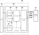
Fig. 2 is the synoptic diagram that the configuration of each unit of controlling according to embodiment of the invention utilization control CPU is shown;
Fig. 3 is the schematic diagram that the overall arrangement of the reflection light quantity that is used for the detection record material is shown;
Fig. 4 is illustrated on the recording materials surface that the cmos sensor according to the image read sensor of the embodiment of the invention reads, analog image and be the synoptic diagram of the contrast between the digital picture after 8 * 8 pixels with the output digital processing of cmos sensor;
Fig. 5 is the process flow diagram that illustrates according to the operational process of the control CPU of the embodiment of the invention;
Fig. 6 is the synoptic diagram that the circuit block diagram of cmos sensor is shown;
Fig. 7 is the block scheme that the control circuit of cmos sensor is shown;
Fig. 8 illustrates the schematic diagram that the irradiation unit that utilizes traditional sensors part shines measured zone acquisition, that be used to carry out skiametry;
Fig. 9 illustrates measured zone acquisition, that be used to carry out skiametry is shone in utilization according to the irradiation unit of the Sensor section of the embodiment of the invention schematic diagram;
Figure 10 illustrates the synoptic diagram of utilization to the image of the irradiates light acquisition of recording materials;
Figure 11 illustrates conventional carry and according to the synoptic diagram of the difference between the conveying of the Sensor section of the embodiment of the invention;
Figure 12 illustrates conventional carry and according to the synoptic diagram of the difference between the conveying of the Sensor section of the embodiment of the invention; And
Figure 13 illustrates conventional time of delivery and according to the synoptic diagram of the difference between the time of delivery of the Sensor section of the embodiment of the invention.
Embodiment
Image-forming apparatus according to the present invention and method are described below with reference to the accompanying drawings.
The present invention is used for universal imaging device as shown in Figure 1.In Fig. 1, imaging device 101 comprises: carton 102, feed rollers 103, conveying roller 124, upper sensor 125, transfer belt driven roller 104, transfer belt 105, yellow, magenta, cyan and black photosensitive drum 106 to 109, colour transfer roller 110 to 113, yellow, magenta, cyan and black box 114 to 117, yellow, magenta, cyan and sodium yellow block learn 118 to 121 and fixation unit 122.
As imaging device, imaging device 101 comprises: optical unit, photosensitive drums, transfer belt 105 and fixation unit 122, and it utilizes electrophotographic processes to be transferred to yellow, magenta, cyan and black image on the recording materials in succession usually, then, utilization comprises the temperature of the toner image that fixation unit 122 controls of fixing roller are transferred, so that it is carried out hot photographic fixing.Dispose versicolor fixation unit 118 to 121, to form sub-image by utilizing laser beam to be exposed to scanning in the surface of photosensitive drums 106 to 109.Make these serial imaging operations synchronous, so that this image is transferred on the recording materials that will carry from the precalculated position.
In addition, imaging device 101 also comprises defeated paper motor, is used to provide and carries recording chart as recording materials, and when being transported to transfer belt and fixing roller, the recording chart that is transferred has and is formed on its lip-deep required image.
Conveying roller 124 is provided by recording chart at a predetermined velocity that provide.Upper sensor 125 detects the forward position of recording chart, then, through the schedule time, stops the conveying operations of recording chart after detecting temporarily.Under this interim halted state, the surface image of sensor unit 123 reading and recording paper.Before stopping, repeatedly carrying out imaging in order to carry out above-mentioned skiametry temporarily.
Before recording chart is delivered to transfer belt, alignment sensor unit 123, then, and to the surface irradiation light of the recording materials that are transferred, focusing on its reflected light and to form image, thus the image of specific region on the reading and recording material surface.
Below with reference to the control CPU 210 of Fig. 2 explanation as the control device of imaging device 101.Control CPU 210 utilizes 122 pairs of recording materials of fixation unit that required heat is provided, so that toner image welding photographic fixing is to recording materials.
Then, utilize Fig. 2 that operational process according to the control CPU of the imaging device of the embodiment of the invention and method is described.Fig. 2 is the synoptic diagram that the configuration of each unit that utilizes control CPU 210 controls is shown.In Fig. 2, control CPU 210 is connected to cmos sensor 211 and versicolor optical unit 212 to 215, optical unit 212 to 215 comprises polygonal mirror, motor and laser instrument, the versicolor optical unit of control CPU 210 control is with to the photosensitive drum surface scan laser and draw required sub-image.Equally, control CPU 210 controls: defeated paper motor 216 is used to carry recording materials; Defeated paper solenoid 217 is used to start the feed rollers that driving is used to carry recording materials; There is sensor 218 in paper, is used for the detection record material and whether is arranged on the precalculated position; High-voltage power supply 219 is used to control the required once charging of electrophotographic processes, development, primary transfer bias voltage and secondary transfer printing bias voltage; Drum drive motor 220 is used to drive photosensitive drums and transfer roll; Band drive motor 221 is used to drive the roller of transfer belt and the roller of fixation unit; Fixation unit; And low-tension supply unit 222.In addition, control CPU 210 utilizes thermistor (not shown) monitor temperature, applying control, thereby makes fixing temperature keep constant temperature.
ASIC 223 is hardware circuits, according to the instruction of control CPU 210, and the motor speed in its control cmos sensor 211 and the fixation unit 212 to 215, but also the speed of the defeated paper motor of control.About the speed control of motor, it detects tach signal (tack signal) from the motor (not shown), then, by motor being applied signal for faster or reduce-speed sign, carries out speed control, so that the interval of tach signal becomes the schedule time.Because a plurality of motors are carried out speed control, so compare with utilizing software controls, it is more favourable to utilize the hardware circuit of ASIC 223 to construct this control circuit.
When receiving the print command of conduct instruction from the principal computer (not shown), control CPU 210 utilizes paper to exist sensor 218 to determine whether to exist recording materials.If paper exists, then control CPU 210 and drive defeated paper motor 216, drum drive motor 220 and band drive motor 221, but also drive defeated paper solenoid 217, so that recording materials are transported to the precalculated position.
If detect the forward position of recording chart from upper sensor 125, through after the schedule time, recording materials are transported to the position of cmos sensor 211, then controlling CPU 210 provides cmos sensor 211 imaging instructions to speed ASIC 223, so that the surface image imaging of 211 pairs of recording materials of cmos sensor.In this case, ASIC 223 activates Sl_select, and then, at the fixed time, the SYSCLK of output predetermined pulse is to catch the imaging data of cmos sensor 211 outputs by Sl_out.
Gain setting about cmos sensor 211, it is provided with the value that control CPU is 210 pre-determined, be positioned at the register of ASIC 223, so that ASIC 223 activates Sl_select, then, export the SYSCLK of predetermined pulse at the fixed time, thereby the gain of cmos sensor 211 is set by Sl_in.
ASIC 223 comprises and is used to realize that following recording materials of the present invention determine the control circuit 702 of devices and methods therefor, and, will be used for determining that the result of calculation of the attribute of recording materials stores register A and the register B that is positioned at control circuit 702 into.In addition, control CPU 210 reads register A and the register B result of calculation interior, that be used for the attribute of definite recording materials that is stored in the control circuit 702, then, and the kind of definite recording materials that provided, thereby control, to change image-forming condition according to this result.
Enumerate the various controls that 210 pairs of image-forming conditions of control CPU carry out below.For example, control, applying the development bias voltage lower, and suppress to adhere to the amount of the lip-deep toner of recording materials, thereby prevent that toner from splashing than blank sheet of paper for the so-called toilet paper that the superficial makings of recording materials is coarse.This is to splash and because a large amount of toners adhere to the problem that makes deterioration of image quality on the surface of recording materials, particularly for toilet paper for toner that the texture that solves because of paper causes.
In addition, control CPU 210 is the kind of definite recording materials that provided also, and according to this result the transporting velocity of recording materials is carried out variable control.By the value by the speed control register of controlling ASIC 223 CPU 210 settings, that be used for execution speed control, control transporting velocity.For example,, change the fixing temperature condition, control, thereby improve the transparency with the raising fixing temperature for transparent record material such as OHT.Can also be according to the kind of recording materials transparent control whether, to change the transporting velocity of recording materials.In addition,, but can improve the fixation performance that sticks to the lip-deep toner of recording materials, to improve gloss and to strengthen picture quality for machine-glazed paper.
Therefore,, utilize hardware circuit, carry out this calculating according to the surface image of the recording materials of cmos sensor imaging by ASIC according to this embodiment.According to this result of calculation, CPU can control, to change development bias condition, the fixing temperature of fixation unit or the transporting velocity of recording materials of high-voltage power supply.
[first embodiment]
Then, explanation is determined device according to the recording materials of the embodiment of the invention.Fig. 3 is the schematic diagram of overall arrangement that is used for the reflection light quantity of detection record material.
As shown in Figure 3, sensor unit 123 comprises: reflection LED 301, as light irradiation device; Recording materials 304; Cmos sensor 211 is as reading device; And imaging len 303.At this, cmos sensor 211 can be a ccd sensor.
LED 301 is as light source in reflection, the surface of its rayed recording materials 304.According to this embodiment, light source is LED.Yet, can also use xenon pipe or Halogen lamp LED.The reflected light of recording materials 304 focuses on by imaging len 303, with imaging on cmos sensor 211.Therefore, can reading and recording material 304 lip-deep images.
According to this embodiment, configuration reflection LED 301, thereby at a predetermined angle to the surperficial oblique fire LED light of recording materials 304, as shown in Figure 3.Yet, can also not tilt to install LED, and utilize unshowned photoconduction skew ray.
Fig. 4 is that recording materials 304 lip-deep analog images that the cmos sensor 211 of sensor unit 123 reads are shown and is the synoptic diagram of the contrast between the digital picture after 8 * 8 pixels with the output digital processing of cmos sensor 211.At this, by utilizing the A/D conversion simulation output of cmos sensor 211 is converted to 8 pixel datas, with digital processing.
In Fig. 4, recording materials A401 is so-called toilet paper, and its lip-deep paper texture is thicker relatively, and recording materials B402 is normally used so-called blank sheet of paper, and recording materials C403 is so-called machine-glazed paper, and their amplification surface image is shown respectively.These images 401 to 403 that cmos sensor 211 is read carry out digital processing, and they become image shown in Figure 4 404 to 406 respectively.Therefore, surface image is according to the kind of recording materials and difference.The main cause that produces this phenomenon is because the different conditions of the texture on the paper surface.
In addition, usually according to the light summation or the average light quantity that are input to each pixel, calculate the reflection light quantity of recording materials.Yet,, can also only use the result of a light-receiving pixel according to this embodiment.~
As mentioned above, according to the reading the result and this result carried out image after the digital processing of the recording materials surface that utilizes cmos sensor 211 to read, the surface state of paper texture that can the identification record material.In addition, can also utilize reflection light quantity to determine recording materials.
Surface for the identification record material, the part surface of reading and recording material, as the digital picture that constitutes by 8 * 8 pixels, then, on the detected image with the throughput direction vertical direction of recording materials on every row in as the picture element density Dmax of maximal density with as the picture element density Dmin of minimum density, to obtain Dmax-Dmin, the every row in 8 row is all provided this value.The value of Dmax-Dmin by average acquisition is determined the quality of materials (smoothness) as the recording materials attribute.
More particularly, if the same with the situation of recording materials A, lip-deep paper coarse texture then produces a large amount of texture shades.Therefore, the significant difference between bright position and the dark position, thus Dmax-Dmin is bigger.By the recording materials that fully compress and smoothness is high, for example the lip-deep image of recording materials C texture shade is still less arranged, thereby Dmax-Dmin is littler for texture.Utilize this quality of relatively determining recording materials, this relatively is a part of information that is used for determining kind.
The binarization view data with the number of edges data (edgenumber data) that obtain every row, thereby is determined the surface irregularity degree.For example, by white portion being distributed " 1 ", and black is partly distributed " 0 ", then, the quantity of " 1 " data division in every row is counted, obtain the number of edges data.
Utilize value and the number of edges data of Dmax-Dmin, surface state that can identification record paper.
Therefore, by image that recording materials surface irradiation light is obtained according to the kind of recording chart and difference.This phenomenon mainly is because the different generations of compressive state of the state of paper superficial makings and paper texture.
The image that requires above-mentioned processor controls that cmos sensor 211 is exported carries out sampling processing, and gains in real time and the filtering computing.Therefore, need to use digital signal processor.
Then, will utilize Fig. 7 that the control circuit of cmos sensor 211 is described.Fig. 7 is the block scheme that the control circuit of cmos sensor 211 is shown.In Fig. 7, comprise as the control CPU 210 of determining section: control circuit 702, cmos sensor 211, interface control circuit 704, counting circuit 705, register A706, register B707 and control register 708.
Then, operational process will be described.Control CPU 210 will represent that the data of the operational order of cmos sensor 211 deliver to control register 708, and then, cmos sensor 211 begins the lip-deep image of recording materials is carried out imaging.More particularly, beginning stored charge on cmos sensor 211.Utilize the Sl_select of interface control circuit 704, select cmos sensor 211, then, produce SYSCLK,, send the imaging data image signal from cmos sensor 211 to utilize the Sl_out signal at predetermined instant.
The counting circuit of control circuit 702 carries out predetermined computation to the imaging data that receives by interface control circuit 704, then, consequent value is stored in the register A706, this value is the mean value of the value of 8 Dmax-Dmin that go, and the value of this Dmax-Dmin is the picture element density Dmax and the difference data with picture element density Dmin of minimum density that has maximal density on the recording materials surface.
The counting circuit of control circuit 702 carries out predetermined computation to the imaging data that receives by interface control circuit 704, then, result of calculation is stored in the register B707, as the number of edges data (for example, the total value of the number of edges of each row) on recording chart surface.According to above-mentioned two values in the register, CPU 210 determines the flatness of recording materials, and this flatness is an attribute of recording materials.
Then, will utilize Fig. 6 that the sensor circuit block scheme is described.Fig. 6 is the synoptic diagram that the circuit block diagram of cmos sensor is shown.In Fig. 6, cmos sensor part 601 has the sensor of 8 * 8 pixels, is similar to a zone in it.In addition, also be provided with: vertical transfer register 602 and 603, output buffer 604, horizontal shifting register 605, system clock 606 and timing generator 607.
Then, operational process will be described.When activating Sl_select signal 613,601 beginnings of cmos sensor part are according to the light stored charge that receives.Then, when providing system clock 606, utilize timing generator 607, the row that vertical transfer register 602 and 603 select progressivelys will be read is to move to output buffer 604 with the data order.
The data that horizontal shifting register 605 will move to output buffer 604 are sent to A/D converter 608.At the fixed time, output interface circuit 609 controls then, in 613 valid periods of Sl_select signal, are exported S_out signal 610 by A/D converter 608 digitized pixel datas.
Utilize the sensor, control circuit etc., the operational process that is used to realize embodiments of the invention is described.The Reference numeral 801 to 808 of Fig. 8 illustrates the irradiation unit that utilizes the traditional sensors part and shines measured zone acquisition, that be used to carry out the shadow data measurement.Similarly, the Reference numeral 901 to 908 of Fig. 9 illustrate utilization according to the irradiation unit of the Sensor section of the embodiment of the invention shine acquisition, be used to carry out the measured zone that shadow data is measured.
At first, illustrate that the removal of images that adopts in this embodiment reads the principle of noise.For the purpose of simplifying the description, as an example, suppose the situation of taking the image (9) among Figure 10 regarded as and utilize 8 * 8 pixels that promptly the cmos sensor of 64 pixels is taken the situation of one page.(9) image comprises the shade component (shading component) of target photographic images character A and optical system and illuminator.At first, when reference object is transferred and move, take 8 images that are used to calibrate.Photographs is that (1) shown in Figure 10 is to (8).In order to calibrate, need be to these averaging of image, because because it is inhomogeneous to stick to the irradiation of dust on the detected object and irradiation unit, they comprise noise component, sticking to the irradiation of dust on the detected object and irradiation unit inhomogeneous is not target information.More particularly, by equalization, can calculate the component (for example, the variation of shade component and pixel sensitivity degree) that does not change, even reference object changes, they are still image and read noise data.
(10) among Figure 10 illustrate the view data that obtains after the equalization.After having carried out above-mentioned shooting and equalization, take required image.In this case, be used to the image proofreaied and correct can carry out target take after shooting.As shooting results, required image is (9) among Figure 10, in order to eliminate the shade component, can utilize equalization image (10) that it is proofreaied and correct, and this equalization image (10) only has the shade component that is calculated.Therefore, can more clearly obtain character " A " as required photographic images.(11) among Figure 10 illustrate by carrying out the image that this correction obtains.
According to this embodiment, this principle is used to obtain the lip-deep more exact image of recording materials, to determine the characteristic of recording materials, for example, has the toilet paper of rough surface or has fine and smooth surperficial machine-glazed paper.More precisely, shadow data is because the image that the reasons such as irradiation unevenness of irradiation unit produce reads noise, at first, and according to when carrying recording materials, utilize sensor repeatedly (being 8 times in above-mentioned example) take a plurality of images that this surface obtains, calculate this shadow data.Then, stopping to take under the state of recording materials, a shot is carried out on this surface, then, eliminated shadow data from this photographs, this shadow data is that the image that as above obtains reads noise.Therefore, can obtain more satisfied recording materials surface image.
The predetermined C mos sensor carries out Polaroid required time cycle the specification of cmos sensor (perhaps according to), and this time cycle is the time cycle that obtains to be used for to determine the view data of recording materials.According to the Polaroid required time cycle, the imaging interval (the repeatedly time interval between the imaging) of sensor unit 123 is set.
At this, with the relation (with reference to figure 1) between the conveying operations of the computation process of the above-mentioned read operation of explanation surface image and shadow data and recording materials.
The paper that provides from carton 102 is transported to feed rollers 124, detects time in the forward position of this paper from upper sensor 125, through after the predetermined period of time, and the surface image of reading and recording paper repeatedly.This predetermined period of time is to arrive the required time cycle of position that can utilize 123 pairs of paper of sensor unit to carry out imaging, and prior basis provides the speed of paper and arrives the distance of sensor unit 123, determines this predetermined period of time.
Feeding recordable paper in read operation repeatedly.Utilize a plurality of reading images to calculate shadow data.Then, recording chart is stopped temporarily, read the surface image of this recording chart again.According to image and the shadow data that read operation reads, obtain the surface image of this recording chart.
In traditional imaging device shown in Figure 8, restart and carry the transporting velocity of recording materials to be set to pre-determined normal speed.Normal speed is to be the image taking speed of formation image at blank sheet of paper.
As mentioned above, said process is carried the recording materials 304 as recording medium, the image that is used to calibrate with shooting.If carry with normal speed, promptly with utilize traditional imaging device shown in Figure 8 on recording materials 304, to develop and identical transporting velocity conveying during photographic fixing image (that is, imaging), recording materials 304 are excessive in the amount that sensor unit passes through for 123 times.Because need comprising, this reason, imaging device can make the enough big zone later passed through (improve the configuration of transporting velocity) of recording materials 304 maintenances from sensor 123.Under normal circumstances, be installed in the back of sensor unit 123 such as the next transport portion of transfer belt driven roller 104, as shown in Figure 1, and it is suitable for preprinting operation in the very approaching position of recording materials 304 being delivered to it.Because this reason requires to have enough big distance between sensor unit 123 and transfer belt driven roller 104, be used to make recording materials 304 to begin to be fed forward, slow down and stop from sensor unit 123.Therefore, traditional imaging device has large-sized shell inevitably, because the fundamental distance that exists recording chart to move.
Therefore, according to the present invention,, when calibrating sensors unit 123, can carry recording materials 304 with the speed lower than normal speed in order to dwindle the distance that recording materials 304 pass through from sensor unit 123.Fig. 9 illustrates the feed status with respect to prior art shown in Figure 8, the displacement of the recording materials that shortened.Figure 11 illustrates the displacement of recording medium and time relation at that time.It is half of normal speed (1) that Figure 11 illustrates by the transporting velocity that makes calibration (2), and the displacement of recording medium is halved.Fig. 5 is the process flow diagram that above-mentioned operational process is shown.Respectively each step is described.
S501: start the operation of determining recording materials.
S502: whether definite process of determining recording materials is carried out.At this, if user's decision in advance there is no need to determine (NO), then this process finishes.
S503:, carry recording materials with the low speed of the speed of carrying out imaging (normal speed) that the comparison recording materials are provided with in advance.
S504: carrying with low speed under the situation of recording materials, repeatedly reading images.
S505: determine to read process and whether finish.At this, if the process that reads is not finished (NO), then this process is returned S503.
S506: utilize a plurality of images that read at step S504, calculating is used to eliminate the image that shines unevenness and reads noise.
S507: under the situation of moving recording material not, the surface image of reading and recording material.
S508: utilize image that reads at S507 and the image that calculates at S506 to read noise data, determine recording materials.
S509: finish to determine operation.
At this, the control operation that CPU 210 carries out according to process flow diagram shown in Figure 5.
As mentioned above, when calibrating sensors, be lower than normal speed, can dwindle the distance of sensor, therefore, can provide the imaging device of small size to next transport portion by the speed that makes recording medium.In addition, can also keep the imaging accuracy of shadow data, with definite accuracy of the material of holding the record.
According to this embodiment, control, stop to carry under the state of recording materials with after when recording materials move, repeatedly taking, take the surface of recording materials.Yet, be not limited thereto, can also it be stopped, taking the surface of recording materials, when recording materials move, repeatedly take then, thereby removal of images reads noise (shade component).
[second embodiment]
Then, second embodiment will be described.Because its basic configuration is identical with first embodiment with control, thus difference only is described, and detailed disposes jointly.For first embodiment, described when being calibrated to image-position sensor (when measuring shadow data), reduce the configuration of the transporting velocity of recording medium.Yet, on the actual imaging device, motor revolution and gear ratio is set, to optimize the motor torque of normal speed.Therefore, when being transformed into low speed, according to the motor revolution and the gear ratio of normal speed, motor torque may be big inadequately, therefore causes rotating fault.Because this reason if exist simple conversion to low speed, no longer can guarantee stable situation of carrying.
To controlling,, carry recording materials with conveying and shut-down operation by repeating the step S503 in the process flow diagram shown in Figure 5 according to the conveying of this embodiment and the repetitive operation that stops.
Therefore, control according to this embodiment, with conveying and the shut-down operation that repeats recording medium, thus the displacement of dwindling recording medium.Figure 12 illustrates the displacement and the time relation of recording medium in this case.In Figure 12, mobile transporting velocity (2) equates with normal transporting velocity (1), by after the mobile schedule time stand-by time being set, shortens the fed distance of move media.According to this embodiment, the speed when mobile is identical with normal speed.Yet, also can be the speed different with normal speed.More particularly, for example, there be not speed to cause under the unsettled situation owing to reducing conveying operations, by making transporting velocity be higher than normal speed, can shorten and determine the required time cycle of recording materials, as long as perhaps can realize purpose of the present invention, this speed can be any speed.
As mentioned above, when calibrating sensors unit 123, can it be moved and take recording materials 304 when stopping, thereby compare, shorten the displacement of recording medium with the situation of carrying with normal speed.Therefore, can shorten distance, thereby the imaging device of small size is provided from sensor unit 123 to next transport portion.In addition, can also keep the imaging accuracy of shadow data, with definite accuracy of the material of holding the record.
About shooting time, should be at the fixed time or random time carry out.
[the 3rd embodiment]
Then, the 3rd embodiment will be described.Because its basic configuration is identical with first and second embodiment with control, thus difference only is described, and detailed disposes jointly.For second embodiment, described by repeating recording medium is moved and stop, shortening the configuration of displacement.In the present embodiment, recording materials 304 are moved and the imaging time of the time that stops and sensor unit 123 synchronous, thereby realize effectively calibration.Specifically, when imaging, recording medium is moved, to realize effective calibration.
Figure 13 illustrate in this case time and the displacement of recording materials 304.In the set time, sensor unit 123 repeats imaging.In high zone of the sensor time (3) shown in the top of Figure 13, sensor unit 123 is taken the image of recording materials 304.For under the situation of the influence of the surface nature that is not subjected to recording materials 304, calibrating sensors unit 123, the image space on the recording medium should be different between last once imaging and this time imaging.If when imaging, recording medium is moved, also can under the situation of the influence of the surface nature that is not subjected to recording medium, calibrate.This be because, compare with under mobile status, carrying out imaging, under static state carry out imaging, can more significantly reduce the influence of the surface characteristics of recording materials, therefore, under former instance, measurement is used to compensate because the shadow data that the light quantity that light source or lens cause changes easily.
Therefore,, make recording medium move once required bee-line by when sensor unit 123 carries out imaging, all the other the time chien shih its keep motionless, this mode is the most effective.In Figure 13, shown in the relation between the time (3) of calibration transporting velocity (2) and the sensor unit 123 of the image of taking recording materials 304, recording medium repeats mobile and stops.In this case, every imaging once, recording medium just moves once.Therefore, after moving and taking necessary number of times, it stops.Therefore, can make the displacement of recording medium the shortest.At this example has been described, in this example, be not continuous the detection time of sensor unit 123, but separate.Yet can be continuous detection time.In addition, in the example of this embodiment, move once in each detection time.Yet,, can carry out two or more times shootings (detection) if displacement is shorter than the displacement of normal speed.
As mentioned above, when calibrating sensors unit 123 (when measuring shadow data), moving and stopping with the detection time of sensor unit 123 synchronously of recording medium can guarantee the accurate substantially of pick up calibration, thereby determine recording medium with good accuracy.In addition, the displacement of recording materials 304 is the shortest, therefore, can shorten the distance from sensor unit 123 to next transport portion, thereby the imaging device of small size is provided.In addition, can also guarantee sensor is realized enough calibration accurately, and can accurately determine recording medium.Therefore, can provide the imaging device that the optimal imaging condition can be set and can form the pin-point accuracy image.
According to the present invention, imaging device comprises: conveying device is used for carrying recording materials with predetermined direction, predetermined speed; Imaging device is used for forming image on the recording materials that conveying device is carried; Light irradiation device is used for the recording materials irradiates light; Image read-out is used to read the light of light irradiation device surface reflection irradiation, that be recorded material, thereby obtains the lip-deep image of recording materials; And reflection-type is determined device, comprise light irradiation device and image read-out, be used to make the lip-deep image of recording materials to be read repeatedly by image read-out, determine the predetermined attribute of recording materials to utilize a plurality of recording materials surface images that obtained, wherein, determine the attribute that device obtains according to reflection-type, this device is determined the kind of recording materials, on these recording materials, to form image, and this reflection-type determines that device comprises conveying control device, when making image read-out reading and recording material, this conveying control device control conveying device is so that the displacement that this displacement compares when carrying at a predetermined velocity is short.Therefore, can shorten the displacement of recording medium, and therefore can shorten the displacement that in imaging device, to guarantee, thereby utilize straightforward procedure to reduce this device size.
According to preferred embodiment the present invention is had been described in detail.According to the above description, it will be understood by those skilled in the art that can change and revise, therefore, claim of the present invention covers all such modifications not breaking away from the present invention more under the situation of wide region.
Claims (11)
1, a kind of imaging device is characterized in that comprising:
Imaging portion is used for forming image on recording medium;
Delivery section is used at a predetermined velocity to imaging portion conveying recording medium;
The reflection-type determination portion comprises: light irradiation element is used for the recording medium irradiates light; Image reading unit spare, be used to read by the light irradiation element irradiation, from the light of the surface reflection of recording medium, thereby obtain the surface image of recording medium, this image reading unit spare obtains this surface image when conveying recording medium;
Carry control part, be used to control delivery section and be worth the transporting velocity that recording medium is set at a predetermined velocity; And
Determination portion when the delivery section conveying recording medium, utilizes a plurality of surface images of the recording medium that image reading unit spare reads to determine the predetermined attribute of recording medium,
Wherein, according to the attribute that the reflection-type determination portion obtains, determination portion is determined the kind of recording medium, and imaging portion is provided with image-forming condition based on the kind of this recording medium,
Wherein, when image reading unit spare obtains the surface image of recording medium, carry the control part setting to be lower than the transporting velocity of preset speed values.
2, imaging device according to claim 1, it is characterized in that: determination portion further comprises calculating unit, be used to utilize the surface image of recording medium to calculate and read the relevant data of noise with image, further make image reading unit spare read the surface image of a recording medium, read the relevant computational data of noise from this image that is obtained, to eliminate with image, thereby to utilize the image of this elimination to determine the predetermined attribute of recording medium.
3, a kind of imaging device is characterized in that comprising:
Imaging device is used for forming image on recording medium;
Conveying device is used at a predetermined velocity to the imaging device conveying recording medium;
The sub-image load-carrying unit is used to carry sub-image;
Developing apparatus by providing developer to the sub-image load-carrying unit, makes sub-image be visualized as the developer image;
Transfer device is used for the recording medium that the developer image of developing apparatus is carried to conveying device;
Fixing device is used for photographic fixing and has transfer device and be transferred to developer record images medium on it;
Reflection-type is determined device, comprising: light irradiation device is used for the recording medium irradiates light; And image read-out, be used to read by the light irradiation device irradiation, from the light of the surface reflection of recording medium, thereby obtain the surface image of recording medium, this image read-out obtains surface image when conveying recording medium;
Conveying control device is used to control conveying device and is worth at a predetermined velocity transporting velocity is set; And
Determine device, when the conveying device conveying recording medium, the surface image of the recording medium that the use image read-out reads is determined the predetermined attribute of recording medium,
Wherein, determine the attribute that a plurality of surface image obtained that device reads according to using by reflection-type, to determine that device determines the kind of recording medium, developing apparatus and fixing device are according to the imaging processing condition corresponding to this kind of determining, on this recording medium, form the developer image
Wherein, when image read-out obtained the surface image of recording medium, the conveying control device setting was lower than the transporting velocity of preset speed values.
4, imaging device according to claim 3, it is characterized in that: determine that device further comprises calculation element, be used to utilize the surface image of a plurality of recording mediums that obtain to calculate and read the relevant data of noise with image, further make image read-out read the surface image of a recording medium, read the relevant computational data of noise from this surface image that is obtained, to eliminate with image, thereby to utilize the image of this elimination to determine the predetermined attribute of recording medium.
5, a kind of formation method is characterized in that comprising:
Supplying step is used to utilize conveying device, at a predetermined velocity to the imaging device conveying recording medium;
Image forms step, is used to utilize this imaging device to form image on the recording medium that conveying device is carried;
The image read step is used for when utilizing the conveying device conveying recording medium, utilizes image read-out to read by the light to surface reflection irradiation, printing medium of the light irradiation device of recording medium irradiates light, thereby obtains the image on recording medium surface; And
Reflective determining step comprises the image read step, is used for the carries out image read step, to determine a plurality of surface images that device reads by using by reflection-type, determines the predetermined attribute of recording medium,
Wherein, image forms step and comprises the step that the image-forming condition of this imaging device is set according to the attribute that obtains,
Wherein, the transporting velocity that is provided with in the image read step is lower than predetermined speed.
6, a kind of recording medium is determined device, it is characterized in that comprising:
Image reading unit is used for the recording medium irradiates light, and the surface image of reading ﹠ recording medium;
Delivery section is used for conveying recording medium;
Carry control part, be used for the feed status of controlling recording medium; And
Determination portion by using a plurality of surface images of the recording medium that image reading unit reads, is determined the attribute of recording medium,
Wherein, carry control part control feed status repeating to carry and stop recording medium,
Wherein, the surface image of reading ﹠ recording medium during image reading unit is carried under feed status.
7, recording medium according to claim 6 is determined device, it is characterized in that: the surface image of the recording medium that the determination portion utilization is obtained, calculate and read the relevant data of noise, and utilize and read the relevant data of noise, determine the predetermined attribute of recording medium with this image with image.
8, recording medium according to claim 6 is determined device, it is characterized in that: when conveying recording medium, image reading unit reads from the light of the surface image reflection of recording medium.
9, recording medium according to claim 6 is determined device, it is characterized in that: by utilize image reading unit repeatedly reading ﹠ recording medium obtain a plurality of surface images of recording medium.
10, a kind of recording medium is determined method, it is characterized in that comprising:
Supplying step is used for conveying recording medium at a predetermined velocity;
The image read step is used for the recording medium irradiates light, and the surface image of reading ﹠ recording medium;
Carry controlled step, be used for the feed status of controlling recording medium; And
Determining step is determined the attribute of recording medium by a plurality of surface images of service recorder medium,
Wherein, this conveying controlled step comprises the step that repeats to carry and stop recording medium, the step of the surface image of reading ﹠ recording medium during this image read step is included in and carries in this conveying controlled step.
11, a kind of imaging device is characterized in that comprising:
Delivery section is used for conveying recording medium;
Imaging portion is used for forming image on the recording medium that delivery section is carried;
Reading part is used for irradiates light on recording medium, and reads the light by the surface reflection of recording medium, thereby obtains the surface image of recording medium; And
Control part by using a plurality of surface images of the recording medium that image reading unit reads, is arranged to the image-forming condition of picture portion,
Wherein, control part repeats to carry and stop recording medium, obtains the surface image of recording medium during reading part is carried under feed status.
Applications Claiming Priority (4)
| Application Number | Priority Date | Filing Date | Title |
|---|---|---|---|
| JP2004101221 | 2004-03-30 | ||
| JP2004101221 | 2004-03-30 | ||
| JP2005073784A JP4756227B2 (en) | 2004-03-30 | 2005-03-15 | Image forming apparatus |
| JP2005073784 | 2005-03-15 |
Publications (2)
| Publication Number | Publication Date |
|---|---|
| CN1677255A CN1677255A (en) | 2005-10-05 |
| CN100501581C true CN100501581C (en) | 2009-06-17 |
Family
ID=35049829
Family Applications (1)
| Application Number | Title | Priority Date | Filing Date |
|---|---|---|---|
| CNB2005100588353A Expired - Fee Related CN100501581C (en) | 2004-03-30 | 2005-03-30 | Imaging device and method and recording medium determination device and method |
Country Status (4)
| Country | Link |
|---|---|
| US (2) | US7715739B2 (en) |
| JP (1) | JP4756227B2 (en) |
| KR (1) | KR100659617B1 (en) |
| CN (1) | CN100501581C (en) |
Families Citing this family (6)
| Publication number | Priority date | Publication date | Assignee | Title |
|---|---|---|---|---|
| US7852521B2 (en) * | 2006-06-06 | 2010-12-14 | Canon Kabushiki Kaisha | Recording medium determination apparatus and image forming apparatus |
| FR2937058B1 (en) * | 2008-10-10 | 2012-01-06 | Arjowiggins | METHOD FOR MANUFACTURING A SAFETY DOCUMENT |
| JP5975790B2 (en) * | 2012-08-24 | 2016-08-23 | キヤノン株式会社 | Image forming apparatus |
| JP6655965B2 (en) * | 2015-11-30 | 2020-03-04 | キヤノン株式会社 | Image forming device |
| JP7119670B2 (en) * | 2018-07-11 | 2022-08-17 | コニカミノルタ株式会社 | image forming device |
| US11496642B2 (en) * | 2020-03-18 | 2022-11-08 | Ricoh Company, Ltd. | Image forming apparatus, image forming method, and image forming system for calculating an image forming condition based on characteristic information of a recording medium |
Citations (2)
| Publication number | Priority date | Publication date | Assignee | Title |
|---|---|---|---|---|
| CN1359034A (en) * | 2000-12-12 | 2002-07-17 | 佳能株式会社 | Imaging equipment and test device |
| CN1452031A (en) * | 2002-04-12 | 2003-10-29 | 佳能株式会社 | Image forming device |
Family Cites Families (20)
| Publication number | Priority date | Publication date | Assignee | Title |
|---|---|---|---|---|
| US5291256A (en) * | 1990-11-02 | 1994-03-01 | Canon Kabushiki Kaisha | Image forming apparatus having opening mechanism for jam clearance |
| JP3294315B2 (en) * | 1992-04-13 | 2002-06-24 | キヤノン株式会社 | Image forming device |
| JPH0735703A (en) * | 1993-06-28 | 1995-02-07 | Kawasaki Steel Corp | Image processing method |
| US5953574A (en) * | 1993-12-17 | 1999-09-14 | Canon Kabushiki Kaisha | Sheet feeding apparatus and image forming apparatus |
| JP2987075B2 (en) * | 1995-04-18 | 1999-12-06 | キヤノン株式会社 | Automatic document feeder, automatic document reader, and image forming apparatus having the same |
| JPH09190113A (en) * | 1996-01-10 | 1997-07-22 | Canon Inc | Recording medium classifying device and recording medium calssifying method |
| JP2001225988A (en) | 2000-02-14 | 2001-08-21 | Canon Inc | Image forming device |
| JP2002059601A (en) * | 2000-08-22 | 2002-02-26 | Canon Inc | Imaging apparatus |
| JP4143333B2 (en) * | 2001-06-29 | 2008-09-03 | 株式会社リコー | Image forming apparatus |
| KR100403591B1 (en) | 2001-08-13 | 2003-10-30 | 삼성전자주식회사 | Discrimanating method of print media |
| JP2003063115A (en) * | 2001-08-24 | 2003-03-05 | Hitachi Koki Co Ltd | Method for recording on continuous form |
| JP4378065B2 (en) * | 2001-10-25 | 2009-12-02 | キヤノン株式会社 | Image forming apparatus |
| KR100428545B1 (en) | 2001-12-29 | 2004-04-29 | 삼성전자주식회사 | Image forming device having differentiating varieties of printing medium and driving controlling method of thereof |
| JP2003228256A (en) | 2002-02-04 | 2003-08-15 | Canon Inc | Image forming apparatus |
| JP4227351B2 (en) * | 2002-04-12 | 2009-02-18 | キヤノン株式会社 | Recording material type discriminating apparatus and image forming apparatus |
| JP4109922B2 (en) * | 2002-08-01 | 2008-07-02 | キヤノン株式会社 | Sheet processing apparatus and image forming apparatus provided with the apparatus |
| JP3870892B2 (en) * | 2002-11-05 | 2007-01-24 | 村田機械株式会社 | Color image reading and recording apparatus |
| KR200314853Y1 (en) | 2003-02-25 | 2003-05-28 | 광진정밀 주식회사 | Spindle for precision centripetal grinder |
| JP4993653B2 (en) * | 2003-10-03 | 2012-08-08 | キヤノン株式会社 | Recording material discriminating apparatus, image forming apparatus and method thereof |
| KR200359561Y1 (en) | 2004-05-13 | 2004-08-21 | 오창윤 | Advertising Pad Including Lenticular Sheet |
-
2005
- 2005-03-15 JP JP2005073784A patent/JP4756227B2/en not_active Expired - Fee Related
- 2005-03-29 US US11/091,626 patent/US7715739B2/en not_active Expired - Fee Related
- 2005-03-30 KR KR1020050026303A patent/KR100659617B1/en active IP Right Grant
- 2005-03-30 CN CNB2005100588353A patent/CN100501581C/en not_active Expired - Fee Related
-
2010
- 2010-03-29 US US12/748,508 patent/US8447196B2/en active Active
Patent Citations (2)
| Publication number | Priority date | Publication date | Assignee | Title |
|---|---|---|---|---|
| CN1359034A (en) * | 2000-12-12 | 2002-07-17 | 佳能株式会社 | Imaging equipment and test device |
| CN1452031A (en) * | 2002-04-12 | 2003-10-29 | 佳能株式会社 | Image forming device |
Also Published As
| Publication number | Publication date |
|---|---|
| US20100183325A1 (en) | 2010-07-22 |
| US20050264638A1 (en) | 2005-12-01 |
| US8447196B2 (en) | 2013-05-21 |
| KR20060044971A (en) | 2006-05-16 |
| JP2005316427A (en) | 2005-11-10 |
| CN1677255A (en) | 2005-10-05 |
| US7715739B2 (en) | 2010-05-11 |
| JP4756227B2 (en) | 2011-08-24 |
| KR100659617B1 (en) | 2006-12-20 |
Similar Documents
| Publication | Publication Date | Title |
|---|---|---|
| JP4454914B2 (en) | Image reading apparatus and image forming apparatus | |
| JP4227351B2 (en) | Recording material type discriminating apparatus and image forming apparatus | |
| CN102375367B (en) | Image forming apparatus | |
| JP2009029622A (en) | Recording material determination apparatus and image forming apparatus | |
| JP4804153B2 (en) | Image forming apparatus | |
| CN100501581C (en) | Imaging device and method and recording medium determination device and method | |
| KR20000027725A (en) | Printer and method for calibrating color registration error | |
| JP3298042B2 (en) | Image forming apparatus and control method of image forming apparatus | |
| JP2005017541A (en) | Image forming method and image forming apparatus | |
| JP4440319B2 (en) | Paper surface detection apparatus and image forming apparatus | |
| JP5506713B2 (en) | Recording material surface detection apparatus and image forming apparatus | |
| JP4700866B2 (en) | Image forming apparatus | |
| JP4110033B2 (en) | Image forming apparatus | |
| JP4857321B2 (en) | Recording paper discrimination device and recording paper discrimination method | |
| JP4857322B2 (en) | Image forming apparatus | |
| JP4314104B2 (en) | Recording material discrimination apparatus and image forming apparatus | |
| US6181907B1 (en) | Paper supply control apparatus in printer and paper supplying method | |
| JP2006184504A (en) | Kind-discriminating device for recording material, and image forming apparatus | |
| JP2008020262A (en) | Recording medium discrimination device, its method, and image forming device | |
| JPS635367A (en) | Printing position correcting device | |
| JPH09247428A (en) | Image processor and its method | |
| JP2001318491A (en) | Device for image formation | |
| JP2005202260A (en) | Image forming apparatus | |
| JP2006133474A (en) | Image forming apparatus |
Legal Events
| Date | Code | Title | Description |
|---|---|---|---|
| C06 | Publication | ||
| PB01 | Publication | ||
| C10 | Entry into substantive examination | ||
| SE01 | Entry into force of request for substantive examination | ||
| C14 | Grant of patent or utility model | ||
| GR01 | Patent grant | ||
| CF01 | Termination of patent right due to non-payment of annual fee | ||
| CF01 | Termination of patent right due to non-payment of annual fee |
Granted publication date: 20090617 |