JP4314104B2 - Recording material discrimination apparatus and image forming apparatus - Google Patents
Recording material discrimination apparatus and image forming apparatus Download PDFInfo
- Publication number
- JP4314104B2 JP4314104B2 JP2003399879A JP2003399879A JP4314104B2 JP 4314104 B2 JP4314104 B2 JP 4314104B2 JP 2003399879 A JP2003399879 A JP 2003399879A JP 2003399879 A JP2003399879 A JP 2003399879A JP 4314104 B2 JP4314104 B2 JP 4314104B2
- Authority
- JP
- Japan
- Prior art keywords
- recording material
- image
- video data
- image forming
- forming apparatus
- Prior art date
- Legal status (The legal status is an assumption and is not a legal conclusion. Google has not performed a legal analysis and makes no representation as to the accuracy of the status listed.)
- Expired - Fee Related
Links
Images


Description
本発明は、記録材判別装置及び画像形成装置に関する。 The present invention relates to a recording material discrimination device and an image forming apparatus.
従来から、複写機、レーザープリンタ等の画像形成装置が知られている。電子写真方式を用いた画像形成装置は、トナー等の現像剤像を担持する像担持体と、像担持体に現像剤を付与することにより像担持体上の潜像を現像剤像として可視化する現像器と、記録材に現像剤像を転写する転写器と、現像剤像が転写された記録材を加熱及び加圧することにより現像剤像を記録材に定着させる定着器を備えているのが一般的である。 Conventionally, image forming apparatuses such as copying machines and laser printers are known. An image forming apparatus using an electrophotographic system visualizes a latent image on an image carrier as a developer image by applying a developer to the image carrier and a developer image such as toner. A developing device, a transfer device for transferring the developer image to the recording material, and a fixing device for fixing the developer image to the recording material by heating and pressing the recording material to which the developer image has been transferred. It is common.
以上のような画像形成装置においては、画像形成装置本体に設けられた操作パネル等から記録材のサイズや種類(以下、紙種ともいう)が指定できるものがある。これは、記録材のサイズや種類によって、記録材に画像を形成するのに望ましい条件があり、そのような条件によって画像形成できるように画像形成装置を制御したいという要求に基づくものである。例えば、現像剤像を記録材に定着させる定着器においては、記録材のサイズや種類により記録材に与えるべき熱量が異なるので、記録材のサイズや種類に応じた定着器の制御条件(例えば、定着温度や定着装置を通過する記録材の搬送速度)を設定するのが望ましい。 Some image forming apparatuses as described above can specify the size and type (hereinafter also referred to as paper type) of the recording material from an operation panel or the like provided in the main body of the image forming apparatus. This is based on a demand for controlling the image forming apparatus so that an image can be formed under such conditions depending on the size and type of the recording material. For example, in a fixing device that fixes a developer image to a recording material, the amount of heat to be applied to the recording material differs depending on the size and type of the recording material, so the control conditions of the fixing device according to the size and type of the recording material (for example, It is desirable to set the fixing temperature and the conveyance speed of the recording material passing through the fixing device.
しかし、近年は、画像形成装置にて用いられる記録材の種類が多くなりつつあり、操作パネル等から予め準備されている設定モードをあらゆる紙種をカバーできるように設けることは現実的ではないことから、CCDセンサやCMOSセンサなどで構成される映像読取部(例えば、記録材の搬送方向及びそれに直交する方向に各々複数画素を有する2次元画像センサ)で記録材の表面を映像として読み取ることで記録材の種類を判別する記録材判別装置が提案されている(例えば、特許文献1参照)。 However, in recent years, the types of recording materials used in image forming apparatuses are increasing, and it is not practical to provide a setting mode prepared in advance from an operation panel or the like so as to cover all types of paper. The surface of the recording material is read as an image by a video reading unit (for example, a two-dimensional image sensor having a plurality of pixels in the conveying direction of the recording material and a direction orthogonal thereto) composed of a CCD sensor, a CMOS sensor, or the like. A recording material discriminating apparatus that discriminates the type of recording material has been proposed (see, for example, Patent Document 1).
このような記録材判別装置においては、記録材の表面を照射するための光源や、記録材の表面からCMOSセンサ等の読取センサに到達するまでに存在するレンズ等に起因して素新品時から使用を重ねるにつれてセンサの受光光量にばらつきが生じることが多く、結果として同じ記録材を映像読取部で読み取ったとしても読み取った映像が時間を経るにつれて異なったものとなってしまう。 In such a recording material discriminating apparatus, a light source for irradiating the surface of the recording material, a lens existing before reaching the reading sensor such as a CMOS sensor from the surface of the recording material, etc. As the use is repeated, the amount of light received by the sensor often varies, and as a result, even if the same recording material is read by the video reading unit, the read video becomes different over time.
また、読取センサが2次元センサであり、光源により照射された記録材表面の一部を映像として読み取る場合には、光源が照射される中心部分の画素に対して周辺部分の画素の受光光量は小さくなってしまう。 In addition, when the reading sensor is a two-dimensional sensor and a part of the surface of the recording material irradiated by the light source is read as an image, the received light amount of the peripheral portion pixel with respect to the central portion pixel irradiated with the light source is It gets smaller.
そこで、特許文献1では、読取センサの映像を補正するために記録材を搬送させつつ、記録材の複数箇所で補正用の映像を読み取り、その補正用の映像に基づいて、記録材の種類を判別したり記録材の種類に応じた画像形成装置の制御をしたりするための映像を補正している。
しかしながら、特許文献1に記載したような記録材判別装置だけで以下の課題がある。 However, only the recording material discriminating apparatus as described in Patent Document 1 has the following problems.
読取センサの映像を補正するための補正映像を得る場合には特許文献1に記載されたように記録材を搬送しつつ映像を読み取ればよいが、記録材の種類を判別したり記録材に応じた画像形成装置の制御をしたりするための映像を得る場合には、記録材の搬送を停止させた状態で映像を読み取るの望ましい。 In order to obtain a corrected image for correcting the image of the reading sensor, it is sufficient to read the image while conveying the recording material as described in Patent Document 1, but it is possible to determine the type of the recording material or according to the recording material. When an image for controlling the image forming apparatus is obtained, it is desirable to read the image in a state where conveyance of the recording material is stopped.
これは、記録材の種類を判別したり記録材に応じた画像形成装置の制御をしたりするための映像からは、記録材の表面の凹凸等を正確に取得することが望ましく、そのためには記録材を停止させた状態で読み取る必要があるからである。 This is because it is desirable to accurately acquire the surface irregularities of the recording material from the image for determining the type of the recording material or controlling the image forming apparatus according to the recording material. This is because the recording material needs to be read in a stopped state.
なお、記録材の種類を判別したり記録材に応じた画像形成装置の制御をしたりするための映像を取得するのに、記録材の搬送をわざわざ停止させることは、記録材の判別や画像形成に要する時間の遅延を引き起こしてしまうので望ましくない。 Note that stopping the conveyance of the recording material in order to acquire the image for determining the type of the recording material or controlling the image forming apparatus according to the recording material can be performed by determining the recording material or the image. This is not desirable because it causes a delay in the time required for formation.
本発明は、上述の課題を解決するためになされたものであり、装置の経年変化にかかわらず記録材の種類を判別したり記録材に応じた画像形成装置の制御をしたりするための映像を正確に読み取りつつ、記録材の判別や画像形成に要する時間の遅延を引き起こすことのない記録材判別装置及び画像形成装置を提供することを目的とする。 The present invention has been made to solve the above-described problems, and is an image for discriminating the type of recording material regardless of aging of the apparatus and controlling the image forming apparatus according to the recording material. An object of the present invention is to provide a recording material discriminating apparatus and an image forming apparatus that do not cause a delay in time required for discriminating a recording material or forming an image while accurately reading the image.
上記目的を達成するために、本発明は、記録材の表面の映像を複数の画素からなる映像データとして読み取る読取手段と、前記読取手段により読み取られた映像データに基づいて、記録材の種類を判別する判別手段と、を有する記録材判別装置であって、前記読取手段は、記録材が搬送されている際に第1の映像データを読み取り、記録材が停止している際に第2の映像データを読み取り、前記判別手段は、前記第1の映像データと前記第2の映像データとの差分映像データに基づいて、記録材の種類を判別することを特徴とする。 In order to achieve the above object, the present invention provides a reading means for reading an image on the surface of a recording material as video data composed of a plurality of pixels, and the type of the recording material based on the video data read by the reading means. a recording material discrimination device including a discriminating means for discriminating for the said reading means reads the first image data when the recording material is conveyed, a second when the recording medium is stopped The video data is read , and the discriminating unit discriminates the type of the recording material based on difference video data between the first video data and the second video data.
また、上記目的を達成するために、本発明は、記録材を搬送する搬送手段と、記録材の表面の映像を複数の画素からなる映像データとして読み取る読取手段と、記録材に画像を形成する画像形成手段と、前記読取手段により読み取られた映像データに基づいて、前記画像形成手段を制御する制御手段と、を有する画像形成装置であって、前記読取手段は、記録材が前記搬送手段に搬送されている際に第1の映像データを読み取り、記録材が停止している際に第2の映像データを読み取り、前記制御手段は、前記第1の映像データと前記第2の映像データとの差分映像データに基づいて、前記画像形成手段を制御することを特徴とする。 In order to achieve the above object, the present invention forms an image on a recording material, conveying means for conveying the recording material, reading means for reading an image on the surface of the recording material as video data consisting of a plurality of pixels, and the like. An image forming apparatus comprising: an image forming unit; and a control unit that controls the image forming unit based on video data read by the reading unit , wherein the reading unit includes a recording material on the conveying unit. reads the first video data when being transported, reads the second image data when the recording material is stopped, said control means, said first video data and the second video data The image forming means is controlled based on the difference video data.
本発明によれば、装置の経年変化にかかわらず記録材の種類を判別したり記録材に応じた画像形成装置の制御をしたりするための映像を正確に読み取りつつ、記録材の判別や画像形成に要する時間の遅延を引き起こすことのない記録材判別装置及び画像形成装置を提供することができる。 According to the present invention, it is possible to determine the recording material and the image while accurately reading the video for determining the type of the recording material and controlling the image forming apparatus according to the recording material regardless of the aging of the apparatus. It is possible to provide a recording material discriminating apparatus and an image forming apparatus that do not cause a delay in time required for formation.
[第1の実施形態]
先ず、本発明の第1の実施形態について説明する。
[First Embodiment]
First, a first embodiment of the present invention will be described.
図1は、第1の実施形態にかかる画像形成装置101の概略構成を示す断面図である。
FIG. 1 is a cross-sectional view illustrating a schematic configuration of an
画像形成装置101は、図1に示すように、複数の記録材Pを積載する用紙カセット102と、用紙カセット102から記録材Pを1枚ずつ給紙するための給紙ローラ103と、像担持体たる中間転写ベルト104と、中間転写ベルト駆動ローラ105と、中間転写ベルト駆動ローラ105により駆動される中間転写ベルトを張架する張架ローラ131と、中間転写ベルトを張架する対向ローラ132とを有する。
As shown in FIG. 1, the
また、画像形成装置101は、像担持体たる感光ドラム106〜109と、カートリッジ114〜117と、カートリッジ内に設けられ感光ドラムの表面を帯電するための帯電ローラ114a〜117aと、帯電ローラ114a〜117aにより所定電位に帯電された感光ドラム106〜109上に画像に応じた静電潜像を形成すべくレーザ光による露光を行う露光ユニット118〜121と、露光ユニット118〜121により感光ドラム106〜109上に形成された静電潜像を現像剤たるトナーで現像する現像ユニット141〜144とを有する。
The
また、画像形成装置101は、感光ドラム106〜109上のトナー像を順次中間転写ベルト104に静電的に転写してカラートナー像を形成するために電圧が印加される1次転写ローラ110〜113と、中間転写ベルト104上のカラートナー像を記録材P上に2次転写するために電圧が印加される2次転写ローラ124と、記録材P上にカラートナー像を熱定着させるための定着ヒータ133を有する定着ローラ122aと加圧ローラ122bとからなる定着ユニット122と、搬送ローラ128により搬送された記録材Pを排紙トレイ130に排紙する排紙ローラ129等を有する。
The
なお、定着ヒータ133上にはサーミスタ134が設けられており、サーミスタ134が検知する温度に基づいて定着ヒータ133に供給する電力が制御される。
A
さらに、画像形成装置101は給紙ローラ103により給紙された記録材Pを、中間転写ベルト104上に形成されたトナー像と同期して2次転写位置T2へ搬送するためのレジストローラ対125と、レジストローラ対により搬送される記録材の有無を検知するレジストセンサ126と、記録材Pの表面を映像として読み取る読取部たる映像読取センサ123を有する。ここで、映像読取センサ123及びレジストセンサ126は、図1に示すようにレジストローラ対125より記録材Pの搬送方向に対して下流に設けられている。この位置に映像読取センサ123を設けたのは、記録材Pの特性(種類、表面の凹凸等のがさつき)を検出するには記録材Pがレジストローラ対125により挟持された状態でぶれのない映像を読み取ることが望ましいからである。
Further, the
なお、画像形成装置101は、給紙ローラ103、レジストローラ対125、2次転写ローラ124及び加圧ローラ122bを駆動するための給紙モータM1と、中間転写ベルト駆動ローラ105、感光ドラム106〜109、帯電ローラ114a〜117a等を駆動するためのドラムモータM2と、搬送ローラ127〜128及び排紙ローラ129を駆動するための搬送モータM3とを有する。
The
次に、図2を用いて映像読取センサ123の詳細を説明する。 Next, details of the image reading sensor 123 will be described with reference to FIG.
図2は、映像読取センサ123の構成を示す断面図である。 FIG. 2 is a cross-sectional view showing the configuration of the image reading sensor 123.
図2において、401は記録材Pの所定領域を照射するための光源としてのLEDであり、402は記録材Pからの反射光を結像するための結像レンズであり、403は記録材Pからの反射光を複数の画素からなる映像として読み取るためのCMOSエリアセンサである。尚、CMOSエリアセンサ403は記録材Pの搬送方向に直交する方向にn画素、搬送方向にm画素の計n×m画素を有するものとして説明するが、搬送方向に直交する方向にn画素、搬送方向に1画素を有するラインセンサで代用することもできる(n、mは2以上の整数とする)。 In FIG. 2, 401 is an LED as a light source for irradiating a predetermined area of the recording material P, 402 is an imaging lens for imaging reflected light from the recording material P, and 403 is the recording material P. This is a CMOS area sensor for reading the reflected light from the light as an image composed of a plurality of pixels. The CMOS area sensor 403 is described as having n pixels in the direction orthogonal to the conveyance direction of the recording material P and m pixels in the conveyance direction. However, the n pixels in the direction orthogonal to the conveyance direction are described. A line sensor having one pixel in the transport direction can be substituted (n and m are integers of 2 or more).
図3は、CMOSセンサユニット403のハードウェア構成を示すブロック図である。図3において、501はCMOSセンサであり、例えば8×8=64画素分の受光素子が2次元に配置される。502、503は垂直方向シフトレジスタであり、CMOSセンサ501から読み出す画素列を選択する。504は出力バッファであり、CMOSセンサ501から読み出された画素列の各電荷を保持する。505は水平方向シフトレジスタであり、出力バッファ504に保持された各電荷を順次選択して出力する。506はシステムクロック(SYSCLK)、507はタイミングジェネレータである。508はA/Dコンバータであり、入力された電荷をデジタル値である画素データに変換する。509は出力インターフェース回路であり、画素データをSl_out信号510として出力する。511は制御回路であり、A/Dコンバータの変換ゲインなどを制御する。
FIG. 3 is a block diagram showing a hardware configuration of the CMOS sensor unit 403. In FIG. 3, reference numeral 501 denotes a CMOS sensor. For example, light receiving elements for 8 × 8 = 64 pixels are two-dimensionally arranged.
なお、システムクロック(SYSCLK)506は後述するエンジンコントローラ301内のCPU302から供給される信号であり、Sl_out信号510はCPU302へ出力する信号である。また、後述するSl_select信号512及びSl_select信号513はCPU302から供給される信号である。
A system clock (SYSCLK) 506 is a signal supplied from a
ここで、CPU302がSl_select信号513をアクディブにすると、CMOSセンサ501は受光した光に基づく電荷の蓄積を開始する。次に、CPU302がシステムクロック506を与えると、タイミングジェネレータ507によって垂直方向シフトレジスタ502及び503がCMOSセンサ501から読み出す画素の列を順次選択し、選択された画素列の各電荷が出力バッファ504に順次保持される。
Here, when the
そして、出力バッファ504に保持された各電荷は、水平方向シフトレジスタ505によってA/Dコンバータ508ヘと転送される。このA/Dコンバータ508でデジタル変換された画素データは、出力インターフェース回路509によって所定のタイミングで制御され、Sl_select信号513がアクティブの期間、Sl_out信号510としてCPU302に出力される。
Each charge held in the output buffer 504 is transferred to the A / D converter 508 by the horizontal shift register 505. The pixel data digitally converted by the A / D converter 508 is controlled by the output interface circuit 509 at a predetermined timing, and is output to the
一方、制御回路511は、CPU302から指定されるSl_in信号512によりA/Dコンバータ508のA/D変換ゲインを可変制御できる。例えば、撮像した映像のコントラストが得られない場合など、制御回路511はゲインを変更し、常に最良なコントラストで撮像することができる。尚、各受光素子の出力はシステムクロック(SYSCLK)506の立ち下りタイミングで出力される。
On the other hand, the control circuit 511 can variably control the A / D conversion gain of the A / D converter 508 by the Sl_in signal 512 specified by the
次に、図4を用いつつ、画像形成装置101の制御構成について説明する。
Next, the control configuration of the
図4は、画像形成装置101の制御構成を示すブロック図である。
FIG. 4 is a block diagram illustrating a control configuration of the
図4において、305はビデオコントローラでありホストコンピュータ等の外部装置から画像データを受信するとともに露光ユニット119〜121が出力する画像信号への展開処理を行うものである。301はエンジンコントローラであり、給紙モータM1、中間転写ベルト駆動ローラM2、搬送モータM3、高電圧供給回路135、露光ユニット119〜121、定着ヒータ133、サーミスタ134、CMOSセンサユニット403等を制御するものである。
In FIG. 4, reference numeral 305 denotes a video controller that receives image data from an external device such as a host computer and performs processing for developing the image signal output by the exposure units 119 to 121. An engine controller 301 controls the paper feed motor M1, the intermediate transfer belt drive roller M2, the transport motor M3, the high voltage supply circuit 135, the exposure units 119 to 121, the fixing
なお、高電圧供給回路135は、1次転写ローラ110〜113、2次転写ローラ124、帯電ローラ114a〜117a等に高電圧を印加するための回路である。
The high voltage supply circuit 135 is a circuit for applying a high voltage to the
また、エンジンコントローラ301はCMOSセンサユニット403を制御するCPU302を有するとともに、CPU302は更に演算部303及び記憶部304を有する。なお、CPU302内の演算部303はセンサ部123で撮影された映像の画像データを処理するものであり、CPU302内の記憶部304は、平均化画像を得るために撮影された校正用の画像データを蓄えるものである。
The engine controller 301 includes a
次に、図5を用いて第1の実施形態における画像形成装置101の動作を説明する。
Next, the operation of the
図5は、第1の実施形態における画像形成装置101の動作を説明するフローチャートである。
FIG. 5 is a flowchart for explaining the operation of the
なお、図5における動作はエンジンコントローラ301が実行する動作として説明する。 The operation in FIG. 5 will be described as an operation executed by the engine controller 301.
また、図5においては1枚の記録材Pにカラートナー画像を形成する場合を想定しているが、複数枚の記録材Pにカラートナー画像を形成する場合には図5のフローチャートの動作が各記録材Pについて並行して実行されるものとする。 5 assumes a case where a color toner image is formed on a single recording material P. However, when a color toner image is formed on a plurality of recording materials P, the operation of the flowchart of FIG. It is assumed that the recording materials P are executed in parallel.
まず、ステップS501でエンジンコントローラ301は、ビデオコントローラ301から記録材Pに画像をプリントすべき旨を示すプリントコマンドを受信したか否かを判定する。 First, in step S <b> 501, the engine controller 301 determines whether a print command indicating that an image should be printed on the recording material P is received from the video controller 301.
エンジンコントローラ301は、プリントコマンドを受信したことに応じてステップS502へ進み、画像形成装置101を画像形成可能な待機状態へ移行させるべく、前回転動作を開始させる。なお、前回転動作とは、高電圧供給回路135から帯電ローラ114a〜117aに高電圧を印加しつつ感光ドラム106〜109をドラムモータM2により回転させることで感光ドラム106〜109の表面を所定電位に帯電する動作をいう。
In response to receiving the print command, the engine controller 301 proceeds to step S502 and starts a pre-rotation operation to shift the
ステップS503でエンジンコントローラ301は、用紙カセット102に積載された記録材Pを給紙すべく給紙モータM1の駆動をソレノイド(不図示)により伝達することで給紙ローラ103を回転させて記録材Pの給紙を開始する。 In step S <b> 503, the engine controller 301 transmits the drive of the paper feed motor M <b> 1 by a solenoid (not shown) to feed the recording material P stacked on the paper cassette 102, thereby rotating the paper feed roller 103 to record the recording material. P feeding starts.
ステップS504で、エンジンコントローラ301は給紙モータM1を駆動することでレジストローラ対125を回転させ、記録材Pを搬送させる。 In step S504, the engine controller 301 drives the paper feed motor M1 to rotate the registration roller pair 125 and convey the recording material P.
ステップS505で、エンジンコントローラ301はレジストセンサ126が記録材Pの先端を検知してON状態となるか否かを判定し、レジストセンサ126がON状態となると、ステップS506へ進む。なお、エンジンコントローラ301は、レジストセンサ126がON状態となったことに応じて記録材PのCMOSセンサユニット403による撮像のために光源であるLED401を発光させる。
In step S505, the engine controller 301 determines whether or not the registration sensor 126 detects the leading edge of the recording material P and is turned on. When the registration sensor 126 is turned on, the process proceeds to step S506. The engine controller 301 causes the
ステップS506で、エンジンコントローラ301はレジストローラ対125により搬送されている記録材Pの先端部分をCMOSセンサユニット403により複数回撮影して映像として読取ることで、シェーディング補正を行うための映像を読み取る。尚、記録材Pの先端位置の検出はレジセンサ126で無くても良く、CMOSセンサユニット403が読み取る画像を処理することで記録Pの先端がCMOSセンサユニット403に到着したことを検出してもよい。 In step S506, the engine controller 301 reads the image for shading correction by photographing the leading end portion of the recording material P conveyed by the registration roller pair 125 a plurality of times by the CMOS sensor unit 403 and reading it as an image. It should be noted that the position of the leading end of the recording material P may not be detected by the registration sensor 126, and it may be detected that the leading end of the recording P has arrived at the CMOS sensor unit 403 by processing an image read by the CMOS sensor unit 403. .
次に、ステップS507で、エンジンコントローラ301はCMOSセンサユニット403により複数回撮影された映像を演算部303へ入力し、演算部303は複数の映像の各画素について平均化処理を行う。具体的には、シェーディング補正を行うために読み取った映像の読取回数で平均化する。
Next, in step S507, the engine controller 301 inputs an image captured a plurality of times by the CMOS sensor unit 403 to the
ステップS508で、エンジンコントローラ301は演算部303が平均化処理を行って生成した映像をシェーディング補正用の映像(映像1)として記憶部305に蓄える。このとき、平均化された画像を更に、隣り合う画素とで平均化し、全体の画素数を落として蓄えることにより、メモリ容量を削減することも可能である。
In step S508, the engine controller 301 stores, in the storage unit 305, a video generated by the
ステップS509で、エンジンコントローラ301は本測定を行うべく記録材Pの搬送を停止させるためにレジストローラ対125の回転を停止させる。レジストローラ対125を停止して紙搬送を停止することで、記録材Pが停止した状態でCMOSセンサユニット403による映像の読み取りが可能となり、確実な映像読み取りが可能となる。 In step S509, the engine controller 301 stops the rotation of the registration roller pair 125 in order to stop the conveyance of the recording material P to perform the main measurement. By stopping the registration roller pair 125 and stopping the paper conveyance, the CMOS sensor unit 403 can read an image with the recording material P stopped, and a reliable image reading is possible.
ステップS510で、エンジンコントローラ301は、記録材Pがレジストローラ対125により挟持された状態で停止したことに応じて画像形成動作を開始する。具体的には、以下の動作を開始する。 In step S <b> 510, the engine controller 301 starts an image forming operation in response to the recording material P being stopped in a state where the recording material P is sandwiched by the registration roller pair 125. Specifically, the following operation is started.
まず始めに、エンジンコントローラ301は、プリントすべき画像情報に応じた静電潜像を感光ドラム106〜109上に形成すべく、露光ユニット118〜121によるレーザ露光を開始する。そして、エンジンコントローラ301は、感光ドラム106〜109上の静電潜像を現像ユニット141〜144によりトナーで現像するとともに、1次転写ローラ110〜113でそのトナー像を中間転写ベルト104上に順次転写して(上流側からイエロー、マゼンタ、シアン、ブラックの各色のトナー画像を重ねて転写する)カラートナー像を形成するべく、高電圧供給回路135を制御する。
First, the engine controller 301 starts laser exposure by the exposure units 118 to 121 in order to form electrostatic latent images on the photosensitive drums 106 to 109 according to image information to be printed. The engine controller 301 develops the electrostatic latent images on the photosensitive drums 106 to 109 with toner by the developing units 141 to 144 and sequentially transfers the toner images onto the
S511にてCMOSセンサユニット403はレジストローラ対125により挟持されつつ搬送停止中の記録材Pの表面映像(映像2)を読み取る。 In S511, the CMOS sensor unit 403 reads the surface image (image 2) of the recording material P that is being transported while being sandwiched by the registration roller pair 125.
ステップS512で、エンジンコントローラ301は、搬送停止中の記録材Pの表面をCMOSセンサユニット403により読み取った映像(映像2)をシェーディング補正用の映像(映像1)を用いて補正することにより、シェーディング成分や画素感度ばらつきなどに影響されない鮮明な映像を得ることができる。なお、補正処理としては映像2の各画素の値から映像2の各画素の値を減算して差分映像を得ることにより行うものとする。 In step S512, the engine controller 301 uses the shading correction image (image 1) to correct the image (image 2) obtained by reading the surface of the recording material P being stopped by the CMOS sensor unit 403, thereby performing shading. It is possible to obtain a clear image that is not affected by variations in components and pixel sensitivity. Note that the correction processing is performed by subtracting the value of each pixel of video 2 from the value of each pixel of video 2 to obtain a differential video.
次に、S513にて記録材Pの種類判別を行う。記録材Pの種類判別は、映像2を映像1で補正した映像である差分映像を用いて、差分映像の表面平滑度を算出して判別する。 In step S513, the type of the recording material P is determined. The type of the recording material P is determined by calculating the surface smoothness of the difference video using the difference video that is the video 2 corrected with the video 1.
この判別方法について、図6、7を用いつつ説明する。 This determination method will be described with reference to FIGS.
図6は、CMOSセンサユニットで読み取った映像1及び映像2の差分画像の一例を示す図である。 FIG. 6 is a diagram illustrating an example of a difference image between video 1 and video 2 read by the CMOS sensor unit.
図6における差分映像は、記録材Pの搬送方向に直交する方向にn(=8)画素を有するもので、それがm(=8)ライン分ある。また、各画素の色は、各画素に対応する受光光量を示すものである。なお、受光光量は最小値が0で、最大値が255の256(8ビット)段階の映像であるとする。 The difference video in FIG. 6 has n (= 8) pixels in a direction orthogonal to the conveyance direction of the recording material P, and there are m (= 8) lines. The color of each pixel indicates the amount of received light corresponding to each pixel. It is assumed that the received light quantity is a 256 (8-bit) step image having a minimum value of 0 and a maximum value of 255.
図7は、図6における差分映像の、搬送方向に直交する方向における1ライン分(図6の第1〜第8ラインのいずれか1ライン)を示す図である。 7 is a diagram illustrating one line (any one of the first to eighth lines in FIG. 6) of the difference video in FIG. 6 in a direction orthogonal to the conveyance direction.
図7(a)は、映像1と映像2の双方を示した図であり、丸印(○)は記憶部304に記憶されているシェーディング補正用の映像である映像1を示し、三角印(△)は搬送停止中の記録材Pの表面を読み取った映像2を示す。LED401が記録材Pを照射する中心位置は映像における中心画素部分(各ラインにおける第4、5番目の画素)であるので、端部の画素である第1画素、第8画素は中心画素に比較して受光光量が少ないことがわかる。
FIG. 7A is a diagram showing both video 1 and video 2, and a circle (◯) indicates video 1 that is a shading correction video stored in the storage unit 304, and a triangle ( (Triangle | delta) shows the image | video 2 which read the surface of the recording material P in the conveyance stop. Since the central position where the
それに対して、図7(b)は映像1から映像2を減算した差分映像を示すものであるが、映像1からシェーディング補正用の映像2を減算した結果、端部の画素(第1画素や第8画素)における受光光量の落ち込みが改善されているのがわかる。 On the other hand, FIG. 7B shows a difference image obtained by subtracting the image 2 from the image 1. As a result of subtracting the image 2 for shading correction from the image 1, the end pixel (first pixel or It can be seen that the drop in the amount of received light in the eighth pixel) is improved.
そして、CPU302内の演算部303は、記録材Pの表面平滑度の算出として、差分映像(図7(b))における最大濃度値(Dmax)と最小濃度値(Dmin)の差分であるDmax−Dminを算出する。これは、記録材Pの種類が違うと、記録材Pの表面の繊維の凹凸(がさつき)が異なることから、その凹凸の度合いを判断するためにDmax−Dminを算出するのである。そして、各ライン毎にDmax−Dminの値を算出してそれらの平均値(又は合計値)を算出する。記録材Pの種類に応じたDmax−Dminの平均値(又はその合計値)を予めエンジンコントローラ301内のメモリ(不図示)等に記憶させておき、CPU302が演算部303が算出したDmax−Dminの平均値(又はその合計値)と、メモリに記憶されている記録材Pの種類に応じた複数のDmax−Dminの平均値(又はその合計値)と比較することで、複数のDmax−Dminの平均値(又はその合計値)うち最も値が近いものに対応する記録材Pの種類を特定し、その種類を記録材Pの種類として判別する。
Then, the
以上のように記録材Pの種類を判別した後のステップS514で、エンジンコントローラ301は、ステップS513にて判別した記録材Pの種類に応じた定着条件を設定する。前述のステップS512にて記録材Pの種類として普通紙、OHTシート、厚紙、グロス紙、グロスフィルム、封筒、薄紙を判別するものとし、それぞれの種類に応じて記録材Pの搬送速度(レジストローラ対125、2次転写ローラ124、定着ユニット122等が記録材Pを搬送する速度)及び定着ヒータ134の設定温度を設定する。図8は、記録材Pの種類ごとに設定する定着条件の具体例を示す図である。なお、エンジンコントローラ301は、サーミスタ134から入力される温度と記録材Pの種類に応じて設定される設定温度とを比較して定着ヒータ134に投入する電力を決定することで定着ヒータ133が記録材Pに与える熱量を制御するものとする。なお、搬送速度を記録材Pの種類に応じて変えているのは、例えば記録材Pが厚紙である場合には厚紙の熱容量が大きいことから定着ヒータ134多くの熱量を与える必要があり、そのために記録材Pの搬送速度を遅くすることで単位時間あたりに記録材Pへ与える熱量を多くするためである。
In step S514 after determining the type of the recording material P as described above, the engine controller 301 sets a fixing condition according to the type of the recording material P determined in step S513. In step S512 described above, plain paper, OHT sheet, thick paper, gloss paper, gloss film, envelope, and thin paper are discriminated as the type of the recording material P, and the conveyance speed (registration roller) of the recording material P is determined according to each type. A pair 125, a speed at which the secondary transfer roller 124, the fixing
次に、ステップS514にて設定された定着条件(画像形成条件)にて記録材P上にトナー像をするべく、ステップS515でエンジンコントローラ301は給紙モータM1を駆動することでレジストローラ対125の駆動を再開させる。なお、この際のレジストローラ対による記録材Pの搬送速度は、ステップS514にて設定された搬送速度とする。なお、レジストローラ対125による記録材Pの搬送再開は、ステップS510にて開始された画像形成動作と同期をとって行うものとする。すなわち、エンジンコントローラ301は、中間転写ベルト104上のカラートナー画像が2次転写位置T2にて記録材Pに転写されるようなタイミングでレジストローラ対125による記録材Pの搬送を再開させるものとする。
Next, in order to form a toner image on the recording material P under the fixing conditions (image forming conditions) set in step S514, the engine controller 301 drives the paper feed motor M1 in step S515 to register the resist roller pair 125. Restart the drive. Note that the conveyance speed of the recording material P by the registration roller pair at this time is the conveyance speed set in step S514. Note that the conveyance of the recording material P by the registration roller pair 125 is resumed in synchronization with the image forming operation started in step S510. That is, the engine controller 301 resumes the conveyance of the recording material P by the registration roller pair 125 at a timing such that the color toner image on the
ステップS516で、エンジンコントローラ301は、中間転写ベルト104上のカラートナー像と同期をとって搬送再開された記録材Pにカラートナー像を2次転写させるべく、高電圧供給回路135を制御して2次転写ローラ124に転写電圧を印加する。
In step S516, the engine controller 301 controls the high voltage supply circuit 135 so that the color toner image is secondarily transferred to the recording material P resumed in synchronization with the color toner image on the
ステップS517で、エンジンコントローラ301は、記録材P上に2次転写されたカラートナー像を記録材Pに定着させるべく定着ユニット122を駆動するとともに、ステップS514にて設定された定着ヒータ設定温度となるよう定着ヒータ133をサーミスタ134の検知結果に基づいて制御する。
In step S517, the engine controller 301 drives the fixing
そして記録材Pへカラートナー像が定着された後のステップS518でエンジンコントローラ301は、搬送モータM3により搬送ローラ127、128及び排紙ローラ129を駆動して記録材Pを搬送させることで、記録材Pを排紙トレイ130に排紙させる。
In step S518 after the color toner image is fixed on the recording material P, the engine controller 301 drives the
以上のように、記録材Pの種類を判別して定着条件を設定し、設定された定着条件にて記録材Pに画像を形成する動作について説明した。 As described above, the operation of determining the type of the recording material P, setting the fixing conditions, and forming an image on the recording material P under the set fixing conditions has been described.
次に、シェーディング補正用の映像1を記憶して、記録材Pの種類を判別するために読み取った映像2との差分をとって補正を行う利点について図9を用いつつ補足説明をする。 Next, a supplementary explanation will be given with reference to FIG. 9 regarding the advantage of storing the shading correction image 1 and taking the difference from the image 2 read in order to determine the type of the recording material P.
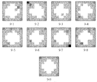
図9は、記録材Pの種類を判別するために記録材Pが搬送されている際に読み取られる映像1と記録材Pが停止している際に読み取られる映像2との差分映像をとって補正を行う利点について補足説明するための図である。 FIG. 9 shows a difference video between an image 1 read when the recording material P is conveyed to discriminate the type of the recording material P and an image 2 read when the recording material P is stopped. It is a figure for explaining supplementarily about the advantage which performs amendment.
記録材Pには一般的に、表面上の不特定の位置にゴミや汚れ等があり、記録材Pを停止させた状態で読み取ると、読み取った映像上ではノイズとして表れてしまう。図9に示す9−1〜9−8は記録材PをCMOSセンサユニット403により複数の位置において停止させた状態で読み取った映像を示したものであり、各々の映像は光源であるLED401が照射される中心位置の受光光量が大きく、周辺部分の受光光量が小さいという傾向があるのとともに、各々の映像でノイズの位置が異なったものとなっている。本来は、記録材Pの種類を正確に判別したいがために、前述の傾向を予め映像(映像1)として読み取っておいて、実際に記録材Pの判別のために記録材Pを停止させた状態で読み取った映像(映像2)の補正に用いることが望ましい。
In general, the recording material P has dust or dirt at unspecified positions on the surface, and when the recording material P is read in a stopped state, it appears as noise on the read image. 9-1 to 9-8 shown in FIG. 9 show images read by the recording material P being stopped at a plurality of positions by the CMOS sensor unit 403, and each image is irradiated by the
しかし、前述の傾向以外に記録材Pの不特定位置に現れるノイズが補正のための映像1に入ってしまうと正確な補正ができないという不具合が生じ得る。この解決策として、記録材Pの複数位置の画像を取得するために記録材Pを停止させた状態で映像を読み取り、更に所定距離搬送させた後に記録材Pを停止させて映像を読み取ることを繰り返し、複数枚の映像を平均化することにより不特定位置に現れるノイズの除去(9−9の映像を得る)を行う方法が考えられる。しかし、この方法では記録材Pの搬送・停止を繰り返すこととなり停止時間の分だけ画像形成を終了するまでの時間が余計にかかってしまう。 However, in addition to the above-mentioned tendency, if noise that appears at an unspecified position of the recording material P enters the video 1 for correction, there may be a problem that accurate correction cannot be performed. As a solution to this, an image is read in a state where the recording material P is stopped in order to acquire images at a plurality of positions of the recording material P, and further, the recording material P is conveyed for a predetermined distance and then the recording material P is stopped and the image is read. A method of removing noise appearing at unspecified positions (obtaining 9-9 images) by averaging a plurality of images repeatedly is conceivable. However, in this method, the conveyance and stop of the recording material P are repeated, and it takes an extra time until the image formation is completed by the stop time.
そこで、図5におけるステップS506では、記録材Pがレジストローラ対125により搬送されている際にシェーディング補正用の映像2を得るための映像読取を行っている。記録材Pが搬送されている際にCMOSセンサユニット403により映像を読み取ると、記録材P上にあるゴミや汚れ等の位置は映像を読み取っている読取期間中にも移動するので、記録材Pを停止した状態で映像を読み取る場合にくらべてノイズの位置が特定の画素のみに影響することが軽減される。換言すれば、ノイズがぼやけた状態として映像が読み取られるので、本来読み取りたい“LED401が照射される中心位置の受光光量が大きく、周辺部分の受光光量が小さいという傾向”のみが映像に反映されることとなる。しかも、記録材Pを搬送している際に読み取るので、搬送・停止を繰り返す必要も無く、画像形成を終了するまでの時間が余計にかかってしまうという問題も生じない。なお、搬送している際の読取期間を十分にとれば1枚の映像のみをシェーディング補正用の映像(映像1)として読み取ることができるが、図5に示したように搬送中の記録材Pの表面を複数回に渡って読み取って、それらの画像の各画素を平均化することでシェーディング補正用の映像(映像1)を得るようにすれば、更に前述の傾向を反映したシェーディング補正用の映像(映像1)を取得することができる。
Therefore, in step S506 in FIG. 5, when the recording material P is conveyed by the registration roller pair 125, image reading for obtaining the image 2 for shading correction is performed. When an image is read by the CMOS sensor unit 403 while the recording material P is being conveyed, the position of dust, dirt, etc. on the recording material P also moves during the reading period during which the image is being read. As compared with the case of reading an image in a state where the image is stopped, it is reduced that the position of the noise affects only a specific pixel. In other words, since the image is read in a state where the noise is blurred, only “the tendency that the received light amount at the central position irradiated with the
例えば、図10示す10−1は、記録材Pを停止させた状態でCMOSセンサユニット403が読み取った映像であり、周辺画素での受光光量の落ち込みやノイズが含まれた映像となっている。この映像から図9におけるシェーディング補正用の映像(映像1)を減算することにより、周辺画素での受光光量の落ち込みやノイズの影響を補正した差分映像として10−2に示す映像を取得することができる。 For example, 10-1 shown in FIG. 10 is an image read by the CMOS sensor unit 403 in a state where the recording material P is stopped, and is an image including a drop in received light amount and noise in peripheral pixels. By subtracting the shading correction video (video 1) in FIG. 9 from this video, it is possible to obtain the video shown in 10-2 as a differential video in which the influence of the drop in the amount of received light and noise at the peripheral pixels is corrected. it can.
なお、以上の説明においては、Dmax−Dminの平均値(又はその合計値)を算出し、その値に基づいて記録材Pの種類を判別することで定着条件を設定するものであってが、記録材Pの種類を判別する工程を実行することなく、Dmax−Dminの平均値(又はその合計値)から直接的に図8に示す定着条件を設定するようにしてもよい。 In the above description, the fixing value is set by calculating the average value of Dmax−Dmin (or the total value thereof) and determining the type of the recording material P based on the calculated value. The fixing conditions shown in FIG. 8 may be set directly from the average value (or the total value) of Dmax−Dmin without executing the step of determining the type of the recording material P.
また、以上の説明においては、記録材Pの種類に応じた定着条件として記録材Pの搬送速度と定着ヒータ設定温度の双方を定着条件として設定するものとしたが、搬送速度又は定着ヒータ設定温度のいずれか一方のみを記録材Pの種類に応じて設定するようにしてもよい。 Further, in the above description, both the conveyance speed of the recording material P and the fixing heater set temperature are set as the fixing conditions as the fixing conditions according to the type of the recording material P. Only one of these may be set according to the type of the recording material P.
以上説明したように、第1の実施形態によれば、装置の経年変化にかかわらず記録材の種類を判別したり記録材に応じた画像形成装置の制御をしたりするための映像を正確に読み取りつつ、記録材の判別や画像形成に要する時間の遅延を引き起こすことのない記録材判別装置及び画像形成装置を提供することができる。 As described above, according to the first embodiment, it is possible to accurately display a video for determining the type of the recording material regardless of the aging of the apparatus and for controlling the image forming apparatus according to the recording material. It is possible to provide a recording material discriminating apparatus and an image forming apparatus that do not cause a delay in time required for discriminating a recording material or forming an image while reading.
[第2の実施形態]
次に、第2の実施形態について説明する。
[Second Embodiment]
Next, a second embodiment will be described.
第2の実施形態は第1の実施形態の変形例であり、記録材Pを照射するための光源であるLED401からの照射光の大部分を反射することなく透過させてしまう透過性の記録材であるOHT(Over Head Transparency)シートに画像形成する場合に特別な制御を行う点が異なる。
The second embodiment is a modification of the first embodiment, and is a transmissive recording material that transmits most of the irradiation light from the
尚、第1の実施形態と同様の構成に関しては、同一符号を付し、その説明を省略する。 In addition, about the structure similar to 1st Embodiment, the same code | symbol is attached | subjected and the description is abbreviate | omitted.
図11は、第2の実施形態における画像形成装置101の動作を説明するフローチャートである。
FIG. 11 is a flowchart for explaining the operation of the
図11におけるステップS1101〜ステップS1118における動作は、第1の実施形態の図5におけるステップS501〜ステップS518と同様の動作である。 The operations in steps S1101 to S1118 in FIG. 11 are the same as the operations in steps S501 to S518 in FIG. 5 of the first embodiment.
図11が図5と異なるのは、ステップS1108とステップS1109との間に実行するステップS1119及びステップS1120の動作である。 FIG. 11 differs from FIG. 5 in the operations of step S1119 and step S1120 executed between step S1108 and step S1109.
記録材Pとして記録材Pを照射するための光源であるLED401からの照射光の大部分を反射することなく透過させてしまう透過性の記録材であるOHT(Over Head Transparency)シートを用いる場合、記録材からの反射光量が小さくなることから、CMOSセンサユニット403が読み取る映像における各画素の受光光量が小さいものとなってしまう。そこで、そのようなOHTシートが給紙された場合は、CMOSセンサユニット403の受光感度(ゲイン)を調整して、受光光量を増幅して記録材Pの種類判別が可能な映像を取得するように制御するのが望ましい。
When an OHT (Over Head Transparency) sheet, which is a transmissive recording material that transmits most of the irradiation light from the
そのため、第2の実施形態では、第1の実施形態に加えてステップS1119及びステップS1120の動作を追加している。 Therefore, in the second embodiment, the operations of step S1119 and step S1120 are added to the first embodiment.
まず、エンジンコントローラ301は、ステップS1119を実行する時点において、既にシェーディング補正用の映像(映像1)を取得して記憶部304に記憶してある。そこで、ステップS1119においてエンジンコントローラ301は、記憶部304に記憶されている8×8=64画素の映像(映像1)における全ての画素の値(0〜255の256段階の値)の平均値(又は合計値)を算出し、その値を予めOHTシートか否かを判別するための閾値と比較することで記録材PがOHTシートであるか否かを判別する。具体的には、OHTシートである場合は受光光量が小さいことから、前述の閾値よりも算出した平均値の方が小さい場合はOHTシートであるとしてステップS1120へ進む。 First, the engine controller 301 has already acquired a shading correction video (video 1) and stored it in the storage unit 304 at the time of executing step S1119. Therefore, in step S1119, the engine controller 301 determines the average value of all the pixel values (256-level values from 0 to 255) in the video (video 1) of 8 × 8 = 64 pixels stored in the storage unit 304 ( (Or a total value) is calculated, and it is determined whether or not the recording material P is an OHT sheet by comparing the value with a threshold value for determining whether or not the sheet is an OHT sheet. Specifically, since the amount of received light is small in the case of an OHT sheet, if the average value calculated is smaller than the above-described threshold value, the process proceeds to step S1120 as an OHT sheet.
ステップS1120でエンジンコントローラ301は、CMOSセンサ403内の制御回路511に対してSl_in信号512によりA/Dコンバータ508のA/D変換ゲインを調整する。具体的には、OHTシートである場合は受光光量が小さいことから、通常よりもA/D変換ゲインを上げて受光光量を増幅させる。これにより、反射光量が少ないOHTシートの表面映像を表面の凹凸が判別できる程度にして読み取ることができる。 In step S <b> 1120, the engine controller 301 adjusts the A / D conversion gain of the A / D converter 508 with respect to the control circuit 511 in the CMOS sensor 403 using the Sl_in signal 512. Specifically, since the amount of received light is small in the case of an OHT sheet, the amount of received light is amplified by increasing the A / D conversion gain than usual. Thereby, the surface image of the OHT sheet with a small amount of reflected light can be read to such an extent that the surface irregularities can be discriminated.
なお、OHTシートであるか否かを判別するだけであれば、ステップS1120にてゲイン調整を行って更に搬送停止中の記録材Pの映像2を読み取る必要は無いが、OHTシートとして複数種類のシート(例えば、レーザビームプリンタ用のOHTシートとインクジェットプリンタ用のOHTシート)の種類を判別する場合には、ステップS1120の動作が必要となる。 Note that if it is only determined whether or not the sheet is an OHT sheet, it is not necessary to perform gain adjustment in step S1120 and further read the image 2 of the recording material P that is being transported, but there are a plurality of types of OHT sheets. In order to determine the type of sheet (for example, an OHT sheet for a laser beam printer and an OHT sheet for an ink jet printer), the operation in step S1120 is required.
例えば、レーザビームプリンタ用のOHTシートと判別した場合と、インクジェットプリンタ用のOHTシートと判別した場合とで、図10のように記録材Pの搬送速度と定着ヒータ設定温度を異ならせるように、エンジンコントローラ301が制御しても良い。また、エンジンコントローラ301は、インクジェットプリンタ用のOHTシートであると判別した場合には、画像形成装置101に適合しないとして画像形成装置101に設けられた操作パネル(不図示)にエラー表示を行うとともに画像形成装置101における画像形成動作を停止させても良い。
For example, the conveyance speed of the recording material P and the fixing heater set temperature are made different as shown in FIG. 10 depending on whether it is determined as an OHT sheet for a laser beam printer or an OHT sheet for an inkjet printer. The engine controller 301 may control. If the engine controller 301 determines that the OHT sheet is for an inkjet printer, the engine controller 301 displays an error on an operation panel (not shown) provided in the
以上説明したように、第2の実施形態によれば、記録材PとしてOHTシートが搬送された場合であっても、OHTシートの種類を判別できるよう映像読取センサ123の受光光量の変換ゲインを適切に調整することができる。 As described above, according to the second embodiment, even when the OHT sheet is conveyed as the recording material P, the conversion gain of the received light amount of the image reading sensor 123 is determined so that the type of the OHT sheet can be determined. It can be adjusted appropriately.
101 画像形成装置
102 用紙カセット
103 給紙ローラ
104 中間転写ベルト
105 中間転写ベルト駆動ローラ
106〜109 感光ドラム
110〜113 1次転写ローラ
114〜117 カートリッジ
118〜121 露光ユニット
122 定着ユニット
123 映像読取センサ
124 2次転写ローラ
125 レジストローラ対
122 レジストセンサ
133 定着ヒータ
134 サーミスタ
301 エンジンコントローラ
302 CPU
303 演算部
304 記憶部
401 LED
403 CMOSセンサユニット
P 記録材
M1 給紙モータ
M2 ドラムモータ
M3 搬送モータ
DESCRIPTION OF
303 Calculation unit 304
403 CMOS sensor unit P Recording material M1 Paper feed motor M2 Drum motor M3 Transport motor
Claims (11)
前記読取手段により読み取られた映像データに基づいて、記録材の種類を判別する判別手段と、を有する記録材判別装置であって、
前記読取手段は、記録材が搬送されている際に第1の映像データを読み取り、
記録材が停止している際に第2の映像データを読み取り、
前記判別手段は、前記第1の映像データと前記第2の映像データとの差分映像データに基づいて、記録材の種類を判別することを特徴とする記録材判別装置。 Reading means for reading the image of the surface of the recording material as video data composed of a plurality of pixels;
A discriminating unit that discriminates the type of the recording material based on the video data read by the reading unit,
It said reading means reads the first image data when the recording material is conveyed,
Read the second video data when the recording material is stopped,
The discriminating means discriminates the type of recording material based on difference video data between the first video data and the second video data.
記録材の表面の映像を複数の画素からなる映像データとして読み取る読取手段と、
記録材に画像を形成する画像形成手段と、
前記読取手段により読み取られた映像データに基づいて、前記画像形成手段を制御する制御手段と、を有する画像形成装置であって、
前記読取手段は、記録材が前記搬送手段に搬送されている際に第1の映像データを読み取り、
記録材が停止している際に第2の映像データを読み取り、
前記制御手段は、前記第1の映像データと前記第2の映像データとの差分映像データに基づいて、前記画像形成手段を制御することを特徴とする画像形成装置。 Conveying means for conveying the recording material;
Reading means for reading the image of the surface of the recording material as video data composed of a plurality of pixels;
Image forming means for forming an image on a recording material;
A control unit that controls the image forming unit based on video data read by the reading unit;
It said reading means reads the first image data when the recording material is conveyed to the conveying means,
Read the second video data when the recording material is stopped,
The image forming apparatus, wherein the control unit controls the image forming unit based on difference video data between the first video data and the second video data.
前記搬送手段は、前記像担持体上に担持された前記画像を記録材に転写すべく、搬送中の記録材を一旦停止させた後に搬送を再開するローラ対を有し、
前記読取手段は、記録材が前記ローラ対にて搬送されている際に前記第1の映像データを読み取り、記録材が前記ローラ対にて停止している際に第2の映像データを読み取ることを特徴とする請求項5乃至10のいずれかに記載の画像形成装置。 The image forming means has an image carrier that carries the image,
The transport means includes a pair of rollers that resumes transport after temporarily stopping the recording material being transported in order to transfer the image carried on the image carrier to the recording material,
The reading unit reads the first video data when the recording material is conveyed by the roller pair, and reads the second video data when the recording material is stopped by the roller pair. The image forming apparatus according to claim 5, wherein the image forming apparatus is an image forming apparatus.
Priority Applications (1)
| Application Number | Priority Date | Filing Date | Title |
|---|---|---|---|
| JP2003399879A JP4314104B2 (en) | 2003-11-28 | 2003-11-28 | Recording material discrimination apparatus and image forming apparatus |
Applications Claiming Priority (1)
| Application Number | Priority Date | Filing Date | Title |
|---|---|---|---|
| JP2003399879A JP4314104B2 (en) | 2003-11-28 | 2003-11-28 | Recording material discrimination apparatus and image forming apparatus |
Publications (3)
| Publication Number | Publication Date |
|---|---|
| JP2005164266A JP2005164266A (en) | 2005-06-23 |
| JP2005164266A5 JP2005164266A5 (en) | 2007-01-18 |
| JP4314104B2 true JP4314104B2 (en) | 2009-08-12 |
Family
ID=34724306
Family Applications (1)
| Application Number | Title | Priority Date | Filing Date |
|---|---|---|---|
| JP2003399879A Expired - Fee Related JP4314104B2 (en) | 2003-11-28 | 2003-11-28 | Recording material discrimination apparatus and image forming apparatus |
Country Status (1)
| Country | Link |
|---|---|
| JP (1) | JP4314104B2 (en) |
Families Citing this family (2)
| Publication number | Priority date | Publication date | Assignee | Title |
|---|---|---|---|---|
| JP4741811B2 (en) * | 2004-06-03 | 2011-08-10 | キヤノン株式会社 | Image forming apparatus |
| JP5783753B2 (en) * | 2011-02-18 | 2015-09-24 | キヤノン株式会社 | Recording material discrimination device |
-
2003
- 2003-11-28 JP JP2003399879A patent/JP4314104B2/en not_active Expired - Fee Related
Also Published As
| Publication number | Publication date |
|---|---|
| JP2005164266A (en) | 2005-06-23 |
Similar Documents
| Publication | Publication Date | Title |
|---|---|---|
| JP5159445B2 (en) | Recording material discrimination apparatus and image forming apparatus | |
| JP4804153B2 (en) | Image forming apparatus | |
| US8229315B2 (en) | Image forming apparatus and control method therefor | |
| JP2008261932A (en) | Color image-forming apparatus and its control method | |
| JP2003302887A (en) | Image forming apparatus and image formation control method | |
| KR20040021523A (en) | Picture Reading Device and Image Forming Apparatus | |
| JP4756227B2 (en) | Image forming apparatus | |
| JP2005017541A (en) | Image forming method and image forming apparatus | |
| JP2009008839A (en) | Image forming apparatus | |
| JP4440319B2 (en) | Paper surface detection apparatus and image forming apparatus | |
| JP4314104B2 (en) | Recording material discrimination apparatus and image forming apparatus | |
| JP4700866B2 (en) | Image forming apparatus | |
| JP2004117734A (en) | Image forming apparatus and its control method | |
| JP5506713B2 (en) | Recording material surface detection apparatus and image forming apparatus | |
| JP7277246B2 (en) | image forming device | |
| JP5028892B2 (en) | Image forming apparatus and print head | |
| JP2006292951A (en) | Image forming apparatus and its control method | |
| JP2009008778A (en) | Image forming device | |
| JP3575259B2 (en) | Image forming device | |
| JP4857322B2 (en) | Image forming apparatus | |
| JP4857321B2 (en) | Recording paper discrimination device and recording paper discrimination method | |
| JP4861442B2 (en) | Image forming apparatus | |
| JP4974111B2 (en) | Image forming apparatus | |
| JP2006184504A (en) | Kind-discriminating device for recording material, and image forming apparatus | |
| JP4741811B2 (en) | Image forming apparatus |
Legal Events
| Date | Code | Title | Description |
|---|---|---|---|
| A521 | Written amendment |
Free format text: JAPANESE INTERMEDIATE CODE: A523 Effective date: 20061121 |
|
| A621 | Written request for application examination |
Free format text: JAPANESE INTERMEDIATE CODE: A621 Effective date: 20061121 |
|
| A977 | Report on retrieval |
Free format text: JAPANESE INTERMEDIATE CODE: A971007 Effective date: 20081203 |
|
| A131 | Notification of reasons for refusal |
Free format text: JAPANESE INTERMEDIATE CODE: A131 Effective date: 20090106 |
|
| A521 | Written amendment |
Free format text: JAPANESE INTERMEDIATE CODE: A523 Effective date: 20090304 |
|
| A131 | Notification of reasons for refusal |
Free format text: JAPANESE INTERMEDIATE CODE: A131 Effective date: 20090331 |
|
| A521 | Written amendment |
Free format text: JAPANESE INTERMEDIATE CODE: A523 Effective date: 20090409 |
|
| TRDD | Decision of grant or rejection written | ||
| A01 | Written decision to grant a patent or to grant a registration (utility model) |
Free format text: JAPANESE INTERMEDIATE CODE: A01 Effective date: 20090512 |
|
| A01 | Written decision to grant a patent or to grant a registration (utility model) |
Free format text: JAPANESE INTERMEDIATE CODE: A01 |
|
| A61 | First payment of annual fees (during grant procedure) |
Free format text: JAPANESE INTERMEDIATE CODE: A61 Effective date: 20090518 |
|
| FPAY | Renewal fee payment (event date is renewal date of database) |
Free format text: PAYMENT UNTIL: 20120522 Year of fee payment: 3 |
|
| R150 | Certificate of patent or registration of utility model |
Free format text: JAPANESE INTERMEDIATE CODE: R150 Ref document number: 4314104 Country of ref document: JP Free format text: JAPANESE INTERMEDIATE CODE: R150 |
|
| FPAY | Renewal fee payment (event date is renewal date of database) |
Free format text: PAYMENT UNTIL: 20120522 Year of fee payment: 3 |
|
| FPAY | Renewal fee payment (event date is renewal date of database) |
Free format text: PAYMENT UNTIL: 20130522 Year of fee payment: 4 |
|
| FPAY | Renewal fee payment (event date is renewal date of database) |
Free format text: PAYMENT UNTIL: 20140522 Year of fee payment: 5 |
|
| LAPS | Cancellation because of no payment of annual fees |