JP5975790B2 - Image forming apparatus - Google Patents
Image forming apparatus Download PDFInfo
- Publication number
- JP5975790B2 JP5975790B2 JP2012185719A JP2012185719A JP5975790B2 JP 5975790 B2 JP5975790 B2 JP 5975790B2 JP 2012185719 A JP2012185719 A JP 2012185719A JP 2012185719 A JP2012185719 A JP 2012185719A JP 5975790 B2 JP5975790 B2 JP 5975790B2
- Authority
- JP
- Japan
- Prior art keywords
- recording material
- image forming
- image
- unit
- size
- Prior art date
- Legal status (The legal status is an assumption and is not a legal conclusion. Google has not performed a legal analysis and makes no representation as to the accuracy of the status listed.)
- Active
Links
Images


Classifications
-
- G—PHYSICS
- G03—PHOTOGRAPHY; CINEMATOGRAPHY; ANALOGOUS TECHNIQUES USING WAVES OTHER THAN OPTICAL WAVES; ELECTROGRAPHY; HOLOGRAPHY
- G03G—ELECTROGRAPHY; ELECTROPHOTOGRAPHY; MAGNETOGRAPHY
- G03G15/00—Apparatus for electrographic processes using a charge pattern
- G03G15/65—Apparatus which relate to the handling of copy material
- G03G15/6529—Transporting
-
- G—PHYSICS
- G03—PHOTOGRAPHY; CINEMATOGRAPHY; ANALOGOUS TECHNIQUES USING WAVES OTHER THAN OPTICAL WAVES; ELECTROGRAPHY; HOLOGRAPHY
- G03G—ELECTROGRAPHY; ELECTROPHOTOGRAPHY; MAGNETOGRAPHY
- G03G15/00—Apparatus for electrographic processes using a charge pattern
- G03G15/65—Apparatus which relate to the handling of copy material
- G03G15/6555—Handling of sheet copy material taking place in a specific part of the copy material feeding path
- G03G15/6558—Feeding path after the copy sheet preparation and up to the transfer point, e.g. registering; Deskewing; Correct timing of sheet feeding to the transfer point
-
- G—PHYSICS
- G03—PHOTOGRAPHY; CINEMATOGRAPHY; ANALOGOUS TECHNIQUES USING WAVES OTHER THAN OPTICAL WAVES; ELECTROGRAPHY; HOLOGRAPHY
- G03G—ELECTROGRAPHY; ELECTROPHOTOGRAPHY; MAGNETOGRAPHY
- G03G2215/00—Apparatus for electrophotographic processes
- G03G2215/00362—Apparatus for electrophotographic processes relating to the copy medium handling
- G03G2215/00535—Stable handling of copy medium
- G03G2215/00556—Control of copy medium feeding
- G03G2215/00599—Timing, synchronisation
-
- G—PHYSICS
- G03—PHOTOGRAPHY; CINEMATOGRAPHY; ANALOGOUS TECHNIQUES USING WAVES OTHER THAN OPTICAL WAVES; ELECTROGRAPHY; HOLOGRAPHY
- G03G—ELECTROGRAPHY; ELECTROPHOTOGRAPHY; MAGNETOGRAPHY
- G03G2215/00—Apparatus for electrophotographic processes
- G03G2215/00362—Apparatus for electrophotographic processes relating to the copy medium handling
- G03G2215/00535—Stable handling of copy medium
- G03G2215/00717—Detection of physical properties
- G03G2215/00734—Detection of physical properties of sheet size
Description
本発明は、シート等の記録材上に画像を形成する機能を備えた、例えば、複写機、プリンタなどの画像形成装置に関するものである。 The present invention relates to an image forming apparatus such as a copying machine or a printer having a function of forming an image on a recording material such as a sheet.
従来、複写機やレーザビームプリンタ等の画像形成装置として、中間転写体を使用する構成を有する画像形成装置が知られている。この画像形成装置は、複数の感光ドラムが中間転写体に接するように並置されており、一次転写工程と二次転写工程とにより、記録材上にカラー画像(多色画像)を形成するものである。
一次転写工程では、感光ドラムの表面に形成されたトナー像が、中間転写体に転写される。この一次転写工程が、複数色のトナー像に対してそれぞれ実行されることにより、中間転写体の表面に複数色のトナー像が重畳転写される。続けて行われる二次転写工程では、中間転写体の表面に形成された複数色のトナー像が、カセットから給送された記録材の表面に二次転写位置で一括して転写される。この時、カセットから給送された記録材は、二次転写位置より手前の所定位置で一時待機した後、中間転写体上のトナー像が二次転写位置に到達するのに合わせて、再給送される。
ところで、画像形成装置にはコストを抑えるために、カセットに記録材サイズ検知機構が設けられていないものがある。
この場合、プリント動作を行いながら、記録材搬送方向の記録材の実際の長さ(以降、記録材長さ)を検知し、検知後はその記録材長さ検知結果に基づいてプリント動作を制御することとなる。具体的には、記録材の記録材長さ検知結果に適した画像形成間隔と給送間隔でプリント動作を行うというものが提案されている(例えば、特許文献1)。
ただし、画像形成装置はA4で製品カタログ上のスループットを定義しているのが一般的であり、A4以下の記録材においてもA4プリント時のスループットを超えないよう(同一)にして設計されるケースがある。そのため、A4サイズに満たない小サイズの記録材をプリントする際は、A4と同じスループットでプリントしている。ここで、スループットとは、単位時間あたりの画像形成枚数をいう。
Conventionally, an image forming apparatus having a configuration using an intermediate transfer member is known as an image forming apparatus such as a copying machine or a laser beam printer. In this image forming apparatus, a plurality of photosensitive drums are juxtaposed so as to contact an intermediate transfer member, and a color image (multicolor image) is formed on a recording material by a primary transfer process and a secondary transfer process. is there.
In the primary transfer process, the toner image formed on the surface of the photosensitive drum is transferred to the intermediate transfer member. By performing this primary transfer process on the toner images of a plurality of colors, the toner images of a plurality of colors are superimposed and transferred onto the surface of the intermediate transfer member. In the subsequent secondary transfer step, the toner images of a plurality of colors formed on the surface of the intermediate transfer member are collectively transferred to the surface of the recording material fed from the cassette at the secondary transfer position. At this time, the recording material fed from the cassette temporarily stands by at a predetermined position before the secondary transfer position, and then re-feeds as the toner image on the intermediate transfer body reaches the secondary transfer position. Sent.
Incidentally, some image forming apparatuses do not include a recording material size detection mechanism in a cassette in order to reduce costs.
In this case, the actual length of the recording material in the recording material conveyance direction (hereinafter referred to as the recording material length) is detected while performing the printing operation, and then the printing operation is controlled based on the detection result of the recording material length. Will be. Specifically, there has been proposed one in which a printing operation is performed at an image forming interval and a feeding interval suitable for the recording material length detection result of the recording material (for example, Patent Document 1).
However, the image forming apparatus generally defines the throughput in the product catalog in A4, and the recording material of A4 or lower is designed so as not to exceed (same) the throughput during A4 printing. There is. For this reason, when printing a recording material having a small size less than A4 size, printing is performed with the same throughput as A4. Here, the throughput refers to the number of images formed per unit time.
上述したように、プリント制御では、記録材を給送し、一時停止し、再給送するという順番で制御が行われる。この制御の中で、記録材を給送し出してから再給送するまでに要する時間は遅れる可能性がある。その要因としては、給送時に給送動作に対する記録材の滑りや、記録材を搬送するローラの摩耗による搬送不良等が考えられる。このように様々な要因で記録材搬送が遅延することを考慮すると、再給送タイミングに対してなるべく早く給送を開始した方が、例え遅延が発生しても記録材の搬送が間に合う可能性は高まる。
小サイズ記録材が指定された場合、上述したように、従来ではA4と同等のスループットで制御されている。これは、A4プリント時と同一の画像形成間隔で画像を形成し、それに合わせて給送タイミングが決定されるということである。その結果、紙を給送するタイミングはA4時と同じタイミングとなる。すなわち、例えばA5サイズでプリントする際、前の記録材を給送し終わったらすぐに次の記録材を給送するのではなく、A4間隔となるよう待ってから給送をするため、記録材サイズに比べて給送開始タイミングが遅くなっている。
As described above, in the print control, the control is performed in the order of feeding the recording material, pausing, and refeeding. In this control, there is a possibility that the time required from feeding the recording material to refeeding may be delayed. Possible causes include slipping of the recording material with respect to the feeding operation during feeding, conveyance failure due to wear of a roller that conveys the recording material, and the like. Considering the fact that the recording material conveyance is delayed due to various factors as described above, it is possible that the conveyance of the recording material will be in time even if a delay occurs if the feeding is started as soon as possible with respect to the refeed timing. Will rise.
When a small size recording material is designated, as described above, conventionally, the recording material is controlled at a throughput equivalent to A4. This means that an image is formed at the same image formation interval as in A4 printing, and the feeding timing is determined accordingly. As a result, the paper feeding timing is the same as that at A4. That is, for example, when printing in A5 size, the recording material is not fed immediately after feeding the previous recording material, but is fed after waiting for the A4 interval. The feeding start timing is delayed compared to the size.
本発明は上記したような事情に鑑みてなされたものであり、予め設定されている画像形成間隔に対応した記録材のサイズよりも小サイズの記録材に画像形成が行われる場合における記録材の給送性能を向上することを目的とする。 The present invention has been made in view of the above-described circumstances, and the recording material in the case where image formation is performed on a recording material having a size smaller than the size of the recording material corresponding to a preset image forming interval. The purpose is to improve feeding performance.
上記目的を達成するために本発明にあっては、
画像形成指示に従って像担持体に画像の形成を開始する画像形成手段と、
前記画像形成手段によって前記像担持体に形成された画像を転写位置において記録材に転写する転写手段と、
記録材を供給する供給手段と、
記録材のサイズを検知する検知手段と、
所定のサイズに応じた時間間隔で前記画像形成指示を出力し、前記画像形成手段によって前記像担持体に画像の形成が開始されてから、所定の時間が経過したタイミングで記録材を供給するように前記供給手段を制御する制御手段と、を有する画像形成装置において、
前記検知手段によって検知された前記記録材のサイズが前記所定のサイズよりも小さい場合、前記制御手段は、前記画像形成指示を出力する前記時間間隔を変更せず、前記画像形成手段によって前記像担持体に画像の形成が開始されてから、前記所定の時間よりも短い時間が経過したタイミングで記録材を供給するように前記供給手段を制御することを特徴とする。
In order to achieve the above object, the present invention provides:
Image forming means for starting the formation of the image on the image bearing member I follow the image forming instruction,
Transfer means for transferring an image formed on the image carrier by the image forming means to a recording material at a transfer position ;
Supply means for supplying the recording material;
Detection means for detecting the size of the recording material;
The image forming instruction is output at a time interval corresponding to a predetermined size, and the recording material is supplied at a timing when a predetermined time has elapsed after the image forming unit starts forming an image on the image carrier. And an image forming apparatus having a control means for controlling the supply means.
When the size of the recording material detected by the detecting unit is smaller than the predetermined size, the control unit does not change the time interval for outputting the image forming instruction, and the image forming unit does not change the image carrier. after formation of the image is started in the body, it characterized that you control the supply means to supply a recording material at a timing a lapse of time shorter than the predetermined time.
本発明によれば、予め設定されている画像形成間隔に対応した記録材のサイズよりも小サイズの記録材に画像形成が行われる場合における記録材の給送性能を向上することが可能となる。 According to the present invention, it is possible to improve the feeding performance of a recording material when image formation is performed on a recording material having a size smaller than the recording material size corresponding to a preset image forming interval. .
以下に図面を参照して、この発明を実施するための形態を例示的に詳しく説明する。ただし、この実施の形態に記載されている構成部品の寸法、材質、形状それらの相対配置などは、発明が適用される装置の構成や各種条件により適宜変更されるべきものであり、この発明の範囲を以下の実施の形態に限定する趣旨のものではない。 DETAILED DESCRIPTION Exemplary embodiments for carrying out the present invention will be described in detail below with reference to the drawings. However, the dimensions, materials, shapes, and relative arrangements of the components described in this embodiment should be appropriately changed according to the configuration of the apparatus to which the invention is applied and various conditions. It is not intended to limit the scope to the following embodiments.
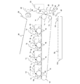
以下に、実施例1について説明する。図1は、本実施例の画像形成装置の概略構成を示す断面図である。
本実施例の画像形成装置は、図1に示すように、イエロー、マゼンタ、シアン、ブラック用のステーション毎に設けられた4個の電子写真感光ドラム(以下、感光ドラム)2a,2b,2c,2dが並置されている。
各感光ドラムの周囲には、その回転方向上流側から順に、一次帯電器7a,7b,7c,7d、現像手段3a,3b,3c,3d、中間転写ベルト10及び一次転写手段4a,4b,4c,4d、クリーニング手段5a,5b,5c,5dが配置されている。
Example 1 will be described below. FIG. 1 is a cross-sectional view illustrating a schematic configuration of the image forming apparatus according to the present exemplary embodiment.
As shown in FIG. 1, the image forming apparatus of this embodiment includes four electrophotographic photosensitive drums (hereinafter referred to as photosensitive drums) 2a, 2b, 2c, provided for each of yellow, magenta, cyan, and black stations. 2d is juxtaposed.
Around each photosensitive drum,
一次帯電器7a,7b,7c,7dは、感光ドラム2a,2b,2c,2dの表面をそれぞれ均一に帯電するための帯電手段である。一次帯電器7a,7b,7c,7dにより一様に帯電された感光ドラム2a,2b,2c,2dの表面は、画像情報に基づいて露光手段1a,1b,1c,1dよりレーザビームが照射されて静電潜像が形成される。ここで、中間転写ベルト10は像担持体に相当する。また、感光ドラム2a,2b,2c,2d、一次帯電器7a,7b,7c,7d、露光手段1a,1b,1c,1d、現像手段3a,3b,3c,3d、及び一次転写手段4a,4b,4c,4dは、トナー像形成手段に相当する。
ここで、各ステーションの構成及び動作は、用いるトナーの色が異なることを除いて実質的に同じである。従って、以下の説明において特に区別を要しない場合は、いずれかの色用に設けられた要素であることを表すために符号に与えた添え字a,b,c,dは省略して総括的に説明する。
The
Here, the configuration and operation of each station are substantially the same except that the color of the toner used is different. Accordingly, in the following description, if there is no particular distinction, the subscripts a, b, c, and d given to the reference numerals are omitted to indicate that they are elements provided for any color, and the overall description is omitted. Explained.
現像手段3は、静電潜像が形成された感光ドラム2の表面に各色のトナー(現像剤)を付着させて、感光ドラム2の表面に形成された静電潜像をトナー画像として顕像化する。クリーニング手段5は、転写後の感光ドラム2の表面に残留したトナーを除去する。
感光ドラム2に対向した位置には、感光ドラム2の表面に形成されたトナー画像が一次転写される中間転写ベルト(中間転写体)10が駆動ローラ11、テンションローラ12及び従動ローラ13により張架されている。
中間転写ベルト10には、中間転写ベルト10上に付着した残トナーを帯電するための残トナー帯電ローラ14が配置されている。残トナー帯電ローラ14は、二次転写を終えた後の中間転写ベルト10上に残留した二次転写残トナーを帯電する。残トナー帯電ローラ14により帯電を受けた二次転写残トナーは中間転写ベルト10上に乗ったまま画像形成ステーションへと移動し、感光ドラム2に逆転写され、そのクリーニング手段5に回収される。
The developing means 3 attaches each color toner (developer) to the surface of the
At a position facing the
The
中間転写ベルト10を挟んで駆動ローラ11に対向する位置には、二次転写装置20が配置されている。二次転写装置20は、二次転写ベルト21が二次転写駆動ローラ23、二次転写テンションローラ24及び二次転写ローラ22に張架されている。そして、二次転写ローラ22は、中間転写ベルト10及び二次転写ベルト21を挟んで駆動ローラ11
に対向する位置に配置されている。ここで、二次転写ローラ22及び駆動ローラ11が対向して配置されることで接触する中間転写ベルト10及び二次転写ベルト21の接触部(二次転写ニップ)は、転写部に相当する。
また、二次転写駆動ローラ23に対向する位置には、二次転写ベルト21上に付着したトナーを除去するための、樹脂ブレード方式の二次転写クリーニング手段25が配置されている。
A
It is arrange | positioned in the position facing. Here, the contact portion (secondary transfer nip) between the
Further, a resin blade type secondary transfer cleaning means 25 for removing the toner adhering to the
各感光ドラム2に形成されたトナー画像は、各一次転写手段4の作用により中間転写ベルト10に一次転写される。一方、載置部としての給送カセット104から、給送手段としてのピックアップローラ31により繰り出された記録材30は、図示しない分離手段により1枚ずつ分離給送される。
次に、搬送ローラ対32によりレジストローラ対33に送られ、レジストローラ対33によって、搬送動作を一時停止された後、所定のタイミングで二次転写ベルト21に向けて搬送される。レジストローラ対33は、ピックアップローラ31により給送された記録材を一時停止可能に設けられ、中間転写ベルト10に形成されたトナー像が二次転写ニップに到達するタイミングに合わせて該記録材を二次転写ニップに向けて給送する再給送手段に相当する。
さらに、二次転写ベルト21に静電的に吸着された状態で、中間転写ベルト10と二次転写ベルト21との間の二次転写ニップに搬送される。そして、中間転写ベルト10に一次転写されたトナー画像が、二次転写ローラ22の作用により二次転写ニップで記録材30に二次転写される。トナー画像が転写された記録材30は、定着手段34によりトナー画像が定着された後、排出ローラ対35により搬送されて、装置本体の上部に設けられた排出トレイ36上に排出される。
The toner image formed on each
Next, the sheet is sent to the
Further, the sheet is conveyed to the secondary transfer nip between the
図2は、画像形成装置に備えられた給送機構を示す概略図である。
ギア100はラックピニオン102を上下駆動するためのもので、図示しないステッピングモータの駆動により回転する。ステッピングモータの回転方向が、正転と反転とで切り替わることで、ラックピニオン102の上方向の駆動と下方向の駆動が切り替わる。給送部103、及び給送部103に接続されたピックアップローラ31は、ラックピニオン102の上下駆動と共に上下駆動を行う。
FIG. 2 is a schematic diagram illustrating a feeding mechanism provided in the image forming apparatus.
The
図2(a)に示すように、給送を行う前は、ピックアップローラ31は、給送カセット104に積載された最上位の記録材30の位置よりも高い位置H1にある。
図2(b)に示すように、給送を行う際は、ギア100が回転し、ピックアップローラ31が、最上位の記録材30の表面に接するまで、ラックピニオン102と給送部103が下降する。その後、ギア100のステッピングモータとは別駆動源のモータによって、ピックアップローラ31を図2(b)中の矢印方向に所定量回転させて、記録材30を1枚ずつ給送する。給送終了後は、ステッピングモータの回転方向が逆方向に切り替わり、ギア100が逆方向に回転してラックピニオン102と給送部103が上昇し、ピックアップローラ31がH1の位置に戻る。
As shown in FIG. 2A, before feeding, the
As shown in FIG. 2B, when feeding, the rack and
図3は、画像形成装置のシステム構成を説明するためのブロック図である。
コントローラ部201は、ホストコンピュータ200、エンジン制御部202と相互に通信が可能となっている。コントローラ部201は、ホストコンピュータ200から画像情報とプリント命令を受け取り、受け取った画像情報を解析してビットデータに変換する。そしてコントローラ部201は、ビデオインターフェイス部210を介して、記録材毎にプリント予約コマンド、プリント開始コマンド、及び、ビデオ信号をエンジン制御部202に送出する。ここで、コントローラ部201及びエンジン制御部202は制御手段を構成している。
FIG. 3 is a block diagram for explaining the system configuration of the image forming apparatus.
The
コントローラ部201は、エンジン制御部202へ、ホストコンピュータ200からのプリント命令に従ってプリント予約コマンドを送信し、プリント可能な状態となったタイミングで、エンジン制御部202へプリント開始コマンドを送信する。また、コントローラ部201は、エンジン制御部202へ、プリント開始コマンドに先立って印字画像の印字率情報を送信する。
The
エンジン制御部202は、コントローラ部201からのプリント予約コマンドの順にプリントの実行準備を行い、コントローラ部201からのプリント開始コマンドを待つ。エンジン制御部202は、プリント指示を受信すると、コントローラ部201に、ビデオ信号の出力の基準タイミングとなる/TOP信号(画像形成指示)を出力し、給送動作を開始する。
給送された記録材は、レジストローラ対33の回転が停止することにより一時待機状態となり、その後、中間転写ベルト10上に形成されたトナー画像が二次転写ニップに到達するのに合わせて、レジストローラ対33によって再給送される。
The
The fed recording material enters a temporary standby state when the rotation of the
図4は、レジセンサ40のメカ機構とその動作の仕組みを説明するための概略図である。図4(a)はレジセンサ40の概略断面図であり、図4(b)〜(d)は、記録材30がレジセンサ40に検知される際の動作について説明するための図である。
レジセンサ40にはフォトインタラプタが適用されており、レジセンサ40は図4(a)に示すように、対向する発光部51と受光部52を持つ。通常は図4(b)のようにメカフラグ53が光を遮っており、記録材がレジセンサ40を通過している時は、図4(c)のように記録材にメカフラグ53が押されて、発光部51から発光された光が受光部52まで到達することで記録材の有無を検知する。
FIG. 4 is a schematic diagram for explaining the mechanical mechanism of the
A photo interrupter is applied to the
記録材30がレジセンサ40に到達すると、メカフラグ53が記録材30に押されて図4(c)に示すような状態になる。その結果、発光部51からの光が受光部52に届くようになり、記録材有りが検知される。その後、図4(d)に示すように、記録材30がレジセンサ40を抜けた後は、センサの構成上、メカフラグ53が再び点線で示す位置60に戻るまでは記録材有りとして検知されていることになる。そのため、レジセンサ40で複数枚の記録材の通過を各々検知するためには、メカフラグ53が位置60に戻るまでの時間を考慮して、各々の記録材の搬送制御をする必要がある。
When the
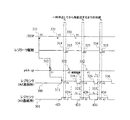
図5は、従来制御におけるプリント時のタイミングチャートである。
300はA4サイズの記録材を連続プリントしたときのレジセンサ40の動作、301は小サイズの記録材をプリントしたときのレジセンサ40の動作を示している。本実施例では小サイズをA5サイズとして説明する。
FIG. 5 is a timing chart at the time of printing in the conventional control.
まず、A4サイズの記録材のプリント動作について説明する。
エンジン制御部202は、コントローラ部201から印字開始コマンドを受信すると、プリントの準備(前回転動作)を開始し、準備が整った時点で/TOP信号を出力して、中間転写ベルト10上に画像形成を開始する(311)。
エンジン制御部202は、/TOP信号出力(311)後、所定時間後に給送動作を開始(312)する。そして、給送された記録材がレジセンサ40に到達したタイミング(313)を基準に、記録材の先端をレジセンサ40と二次転写ローラ22の間の所定の位置(以降、一時停止位置)に記録材を一時停止させる(314)。
その後、エンジン制御部202は、中間転写ベルト10上に形成された画像に合わせて、記録材の搬送を再開して、記録材の所望の位置に中間転写ベルト10上のトナー画像を転写する(315)。
First, a printing operation of an A4 size recording material will be described.
When the
The
Thereafter, the
連続プリントする場合、エンジン制御部202は以下の2つの条件を満たす様に/TO
P信号を出力する。
(1)連続で搬送させる記録材の後端と先端をレジセンサ40で検出できる。
(2)給送した記録材が、再給送タイミングまでに一時停止位置に到達している。
In the case of continuous printing, the
P signal is output.
(1) The
(2) The fed recording material has reached the temporary stop position by the refeed timing.
上記条件のうち(1)は、図4で説明したように、メカフラグの公差によって決まる(メカフラグが所定位置に戻ることができる時間T1(図4,5参照)を確保する)の対し、(2)は、記録材の質やローラの摩耗等の外的要因によって大きく影響を受ける。
これらの影響によって給送した記録材が再給送タイミングまでに到達できなかった場合には、記録材の所望の位置にトナー画像を転写できず、搬送不良起因のミスプリントとなる(正常な印字ができない)。
従って、連続印字を行う場合、給送してから再給送するまでの時間が長ければ長いほどミスプリントは発生しづらい(搬送マージンが大きい)ことになる。給送してから再給送までの時間が長いほど、一時停止してからの再給送するまでの待ち時間T0(図5参照)が長くなることを意味している。通常、給送してから再給送までの時間はスループットを定義している記録材(本実施例ではA4)を対象に記録材の種類による滑り、又はローラの摩耗があっても、搬送が間に合うような最小の間隔に設定している。
Of the above conditions, as described in FIG. 4, (1) is determined by the tolerance of the mechanical flag (to ensure the time T1 (see FIGS. 4 and 5) at which the mechanical flag can return to the predetermined position). ) Is greatly affected by external factors such as recording material quality and roller wear.
If the recording material fed due to these effects cannot reach the re-feed timing, the toner image cannot be transferred to a desired position on the recording material, resulting in a misprint due to a conveyance failure (normal printing Can not).
Accordingly, when continuous printing is performed, misprinting is less likely to occur (the conveyance margin is large) as the time from feeding to refeeding is longer. This means that the longer the time from feeding to re-feeding, the longer the waiting time T0 (see FIG. 5) from the temporary stop to re-feeding. Normally, the time from feeding to re-feeding is not affected by slipping due to the type of recording material or roller wear for the recording material (A4 in this embodiment) defining the throughput. The minimum interval is set in time.
次に、A5サイズの記録材のプリント動作について説明する。
A4より小さいサイズの記録材を連続プリントする場合、上述したようにA4サイズと同じプリント動作を行うことが多い。
従って、A4サイズよりも小さいサイズの記録材(本実施例ではA5)をプリントする際は、/TOP信号出力タイミング(311,321,331)や、給送動作開始タイミング(312,322,332)は、A4サイズプリント時と同じになる。
Next, a printing operation of an A5 size recording material will be described.
When a recording material having a size smaller than A4 is continuously printed, the same printing operation as that of the A4 size is often performed as described above.
Therefore, when printing a recording material having a size smaller than the A4 size (A5 in this embodiment), the / TOP signal output timing (311, 321, 331) and the feeding operation start timing (312, 322, 332) Is the same as during A4 size printing.
そのため、給送動作開始タイミング(312,322,332)で給送されたA5サイズの記録材がレジセンサ40に到達するタイミング(413,423,433)は、A4サイズの場合(323,333)と同じになる。さらに、一時停止位置での一時停止(324,334)や、再給送タイミング(325,335)も同じになる。但し、A5サイズの記録材は、A4よりもサイズが小さいため、A5プリント時に記録材がレジセンサ40を抜けるタイミング(416,426,436)はA4プリント時よりも早く、紙間距離T2がA4プリント時よりも広がることになる(T2>T1)。
Therefore, the timing (413, 423, 433) at which the A5 size recording material fed at the feeding operation start timing (312, 322, 332) reaches the
このように、A5プリント時は、紙間距離T2は広がるが、一時停止してから再給送するまでの時間T0はA4プリント時と変わらない。紙間距離T2は上述した通り、レジセンサ40で記録材を検出可能な時間T1だけ確保できれば充分である。従って、「T2−T1」で空いた時間を、一時停止から再給送までの時間T0を広げる方に使うことができれば、上記の記録材搬送の遅れに対する搬送マージンを増やすことができる。
As described above, during the A5 printing, the inter-paper distance T2 increases, but the time T0 from the temporary stop to the re-feeding is the same as that during the A4 printing. As described above, it is sufficient for the inter-paper distance T2 to ensure only the time T1 during which the
以上を鑑みて本実施例では、小サイズ記録材のプリント時に広がる紙間距離時間(T2−T1)を一時停止から再給送するまでの時間に使うことで、記録材搬送遅れに対する搬送マージンを増やす手法を提案する。 In view of the above, in the present embodiment, the inter-paper distance time (T2-T1) that is widened when printing a small-size recording material is used as the time from the temporary stop to the re-feeding, thereby reducing the conveyance margin for the recording material conveyance delay. Suggest a method to increase.
図6は、本実施例におけるA5サイズプリント時のタイミングチャートである。
エンジン制御部202は、1枚目(先行する記録材)の/TOP信号(511)を出力し、後続の記録材に対する/TOP信号(521)をA4プリント時と同じ間隔で出力する。エンジン制御部202は、各々の/TOP信号(511,521)出力後、A4プリント時と同じタイミングで給送動作を開始する(512,522)。
FIG. 6 is a timing chart at the time of A5 size printing in the present embodiment.
The
ここで、1枚目の/TOP信号(511)が出力されてから、後続の記録材に対する/TOP信号(521)が出力されるまでの時間間隔(画像形成間隔)は、予め記憶されて
いる。この画像形成間隔は、記録材のサイズに対応して予め記憶されるものである。
そして、本実施例の画像形成装置では、この画像形成間隔として予め記憶された値のうちの最小値に対応する記録材(第1記録材)のサイズ(A4)よりも小さいサイズ(A5)の記録材(第2記録材)に対して画像形成可能に構成されている。
Here, the time interval (image formation interval) from when the first / TOP signal (511) is output until the / TOP signal (521) for the subsequent recording material is output is stored in advance. . This image forming interval is stored in advance corresponding to the size of the recording material.
In the image forming apparatus of this embodiment, the size (A5) is smaller than the size (A4) of the recording material (first recording material) corresponding to the minimum value among the values stored in advance as the image forming interval. An image can be formed on the recording material (second recording material).
エンジン制御部202は、1枚目の記録材の先端がレジセンサ40に到達(513)してから、記録材後端がレジセンサ40を抜ける(516)までの時間から、1枚目の記録材の搬送方向長さ(記録材長さ、紙長)を確定する。ここで、エンジン制御部202及びレジセンサ40は検知手段を構成している。
エンジン制御部202は、/TOP信号を出力した時点で、1枚目の記録材長さ検知が終了(517)している場合には、検出結果に基づいて給送開始タイミングを決定する。1枚目の記録材長さ検知が終了していない場合には、A4プリント時と同じタイミングで給送動作を開始する。
本実施例では、図6に示すように、1枚目の記録材長さ検知が終了するタイミングは2枚目の/TOP信号の後であるので、3枚目以降の給送タイミングを早めることになる。
The
If the first recording material length detection is completed (517) at the time when the / TOP signal is output, the
In this embodiment, as shown in FIG. 6, the timing at which the first recording material length detection ends is after the second / TOP signal, so that the feeding timing for the third and subsequent sheets is advanced. become.
検出結果に基づいて給送タイミングを算出する計算式は、給送タイミング変更前の給送タイミングをA、変更後の給送タイミングをBとすると、以下の通りである(図6参照)。
B=A−(T4−T1)
T1は上述の通り、レジセンサ40のメカフラグが元の位置に戻るのに要する時間であるため、最低限確保する必要のある時間である。そのため、現在の空き時間T4からT1を引いた差分だけ、給送タイミングを早めることができる。
給送タイミングを早めることで、記録材が一時停止位置に到達してから再給送までの期間(T5)が、A4プリント時の期間(T3)よりも広がり、搬送マージンを大きくする事ができる。
The calculation formula for calculating the feeding timing based on the detection result is as follows, assuming that the feeding timing before the feeding timing change is A and the feeding timing after the change is B (see FIG. 6).
B = A- (T4-T1)
Since T1 is the time required for the mechanical flag of the
By advancing the feeding timing, the period (T5) from when the recording material reaches the temporary stop position to the re-feeding is longer than the period (T3) at the time of A4 printing, and the conveyance margin can be increased. .
図7は、本実施例における、プリント時のエンジン制御部202の制御内容を示すフローチャートである。
プリント動作の開始時、エンジン制御部202は、まず、給送タイミングをA4プリント時のタイミングに設定する(601)。その後/TOP出力タイミングになるのを待ち、/TOP出力タイミングになった時点(602)で、記録材長さ検知が終了しているかを確認する(603)。記録材長さ検知がまだ終了していない場合は、/TOP信号を出力し(605)、設定された給送タイミング(A4プリント時のタイミング)になった時点で、給送動作を開始する(605,606)。
FIG. 7 is a flowchart showing the control contents of the
At the start of the printing operation, the
一方、/TOP出力タイミング(602)で、記録材長さ検知が終了している場合は、検知した記録材サイズに応じた給送タイミングを設定した後、/TOP信号を出力する(603,604,605)。その後、検知した記録材長さに応じた給送タイミングになったときに給送を開始する(606,607)。
エンジン制御部202はプリントを継続する場合は以上の動作を繰り返す(608)。
On the other hand, if the recording material length detection is completed at the / TOP output timing (602), the feeding timing corresponding to the detected recording material size is set, and then the / TOP signal is output (603, 604). 605). Thereafter, the feeding is started when the feeding timing corresponding to the detected recording material length is reached (606, 607).
The
以上説明したように、本実施例の画像形成装置では、画像形成間隔として予め記憶された値のうちの最小値に対応する記録材サイズ(A4)よりも小さいサイズ(A5)の記録材に対して画像形成可能に構成されている。
そして、小サイズ(A5)の記録材での連続プリントにおいて、記録材長さ検知が終了した後は、画像形成間隔はA4プリント時の間隔で行い、給送タイミングは記録材長さの検知結果(小サイズ)に応じたタイミングで行うことを特徴としている。
すなわち、A5サイズの連続プリント時では、/TOP信号が出力されてから、ピックアップローラ31の給送動作開始までの時間が、A4連続プリント時よりも短くなるよう
に設定されている。このことで、ピックアップローラ31の給送動作開始から、レジストローラ対33の給送動作開始までの時間が、A4連続プリント時よりも長くなる。これにより、スループットを落とすことなく給送性能を向上することができる。すなわち、小サイズの記録材のプリント時に、記録材サイズに応じた給送タイミングを用いることで、記録材の給送や搬送の遅延に対するマージンを広げることができる。
As described above, in the image forming apparatus according to the present embodiment, the recording material having a size (A5) smaller than the recording material size (A4) corresponding to the minimum value among the values stored in advance as the image forming interval is used. Thus, image formation is possible.
Then, in continuous printing with a small size (A5) recording material, after the recording material length detection is completed, the image formation interval is performed at the interval of A4 printing, and the feeding timing is the detection result of the recording material length. It is characterized by being performed at a timing according to (small size).
That is, during A5 size continuous printing, the time from when the / TOP signal is output until the
ここで、記録材サイズをユーザが指定可能な構成の画像形成装置においても、本発明を好適に適用することができる。上述のように、本実施例ではプリントされる記録材の実際のサイズを検知しているので、指定されたサイズとプリントされる記録材のサイズが異なる場合であっても、プリントされる記録材のサイズをより正確に検知することができる。これにより、プリントされる記録材に応じた給送タイミングでプリントを行うことができる。
また、記録材サイズをユーザが指定可能な構成の画像形成装置であって、上述のような記録材サイズを検出する手段が設けられていない画像形成装置においても、本発明を好適に適用することができる。また、記録材を検出する手段としては、上述したような給送された記録材のサイズを検出するレジセンサ40に限るものではなく、例えば、給送カセット104に載置されている記録材のサイズを検出するものであってもよい。
また、本実施例では、像担持体として中間転写ベルトを適用し、一次転写工程と二次転写工程とにより記録材上にカラー画像(多色画像)を形成する中間転写方式の画像形成装置について説明したが、これに限るものではない。例えば、記録材を担持搬送するベルト部材が設けられ、転写工程において、ベルト部材に担持搬送された記録材に転写させる方式の画像形成装置であってもよく、像担持体として感光ドラムが適用された単色画像を形成する画像形成装置であってもよい。すなわち、給送手段により給送された記録材を一時停止可能に設けられ、像担持体に形成されたトナー像が転写部に到達するタイミングに合わせて該記録材を転写部に向けて給送する再給送手段を備えた画像形成装置であれば、本発明を好適に適用できる。
Here, the present invention can also be suitably applied to an image forming apparatus configured to allow the user to specify the recording material size. As described above, since the actual size of the recording material to be printed is detected in this embodiment, even if the designated size and the size of the recording material to be printed are different, the recording material to be printed Can be detected more accurately. As a result, printing can be performed at a feeding timing corresponding to the recording material to be printed.
In addition, the present invention is preferably applied to an image forming apparatus having a configuration in which a recording material size can be designated by a user and not provided with a means for detecting the recording material size as described above. Can do. The means for detecting the recording material is not limited to the
In this embodiment, an intermediate transfer type image forming apparatus that applies an intermediate transfer belt as an image carrier and forms a color image (multicolor image) on a recording material by a primary transfer process and a secondary transfer process. Although explained, it is not limited to this. For example, it may be an image forming apparatus of a type provided with a belt member for carrying and conveying a recording material and transferring it to the recording material carried and conveyed by the belt member in the transfer process, and a photosensitive drum is applied as the image carrier. Alternatively, the image forming apparatus may form a single color image. In other words, the recording material fed by the feeding means is provided so as to be capable of being temporarily stopped, and the recording material is fed toward the transfer portion in accordance with the timing at which the toner image formed on the image carrier reaches the transfer portion. The present invention can be suitably applied to any image forming apparatus provided with a refeeding unit.
以下に、実施例2について説明する。
上述した実施例1では、給送部のピックアップローラ31に断面円形状のローラを用いており、ローラの回転量に応じた距離だけ記録材が搬送される給送構成であった。これに対して本実施例では、ピックアップローラ31にDカットローラを用いており、ピックアップローラ31の回転回数を考慮して画像形成間隔、給送間隔を変更(設定)することを特徴とするものである。ここで、Dカットローラ(Dローラ)は、外周面の一部が回転軸方向に沿って切り欠かれ、回転することにより外周面で記録材を送り出すローラに相当する。なお、本実施例においては、実施例1に対して異なる構成部分について述べることとし、実施例1と同様の構成部分については、その説明を省略する。
Example 2 will be described below.
In the first embodiment described above, a roller having a circular cross section is used as the
図8は、画像形成装置に備えられた給送機構を示す概略図である。
本実施例の給送機構において、実施例1との違いは、ピックアップローラ31にDカットローラを用いている点である。図8(b)に示すように、ピックアップローラ31が図中の矢印の方向に1回転することで、A4サイズの記録材30が1枚給送可能に構成されている。このように本実施例では、ピックアップローラ31が1回転し、A4サイズの記録材30が所定距離搬送されることで、給送動作が行われる。
FIG. 8 is a schematic diagram illustrating a feeding mechanism provided in the image forming apparatus.
In the feeding mechanism of the present embodiment, the difference from the first embodiment is that a D-cut roller is used as the
図8(c)は、給送動作が正常に行われた場合の記録材30の位置を示す概略図である。ピックアップローラ31が1回転すると共に、搬送ローラ対32、レジストローラ対33によって搬送されることで、記録材30はレジセンサ40に到達する。
図8(d)は、給送時に、記録材30の滑りやピックアップローラ31の摩耗等によって、所定距離、記録材30を搬送できなかった場合の記録材30の位置を示す概略図であ
る。例えば封筒のような小サイズの記録材を通紙する場合、ピックアップローラ31が滑ってしまい、ピックアップローラ31の1回の回転では正常に給送することができないことが懸念される。このような場合、小サイズの記録材30は、搬送ローラ対32まで到達していない(ローラ対に挟まれていない)ため、搬送ローラ対32により搬送されることはない。従って、ピックアップローラ31をもう一度、回転させる(以降、給送リトライ)必要がある。
FIG. 8C is a schematic diagram showing the position of the
FIG. 8D is a schematic diagram illustrating the position of the
本実施例では、A4サイズの記録材を給送する場合には、スループットの向上のため、ピックアップローラ31を1回転させることで給送動作を行っている。そして、小サイズの記録材を給送する場合には、確実に記録材の給送動作を行うために、ピックアップローラ31を2回転させて給送リトライを実行するような構成としている。
In this embodiment, when feeding an A4 size recording material, the feeding operation is performed by rotating the
図9は、本実施例におけるA5サイズプリント時のタイミングチャートである。
記録材長さ検知するまでの制御は、実施例1(図6)と同様のため省略する(817まで)。
エンジン制御部は、/TOP信号を出力した時点で、1枚目の記録材長さ検知が終了(817)している場合には、検出した記録材長さ結果に基づいて給送開始タイミングを決定し、3枚目以降の給送タイミングを早める(832)。給送タイミングの算出方法は実施例1と同様のため省略する。
FIG. 9 is a timing chart at the time of A5 size printing in the present embodiment.
Since the control until the recording material length is detected is the same as that in the first embodiment (FIG. 6), it is omitted (up to 817).
If the first recording material length detection is completed (817) at the time when the / TOP signal is output, the engine control unit sets the feeding start timing based on the detected recording material length result. Decide and advance the feeding timing for the third and subsequent sheets (832). Since the method for calculating the feeding timing is the same as that in the first embodiment, the description thereof is omitted.
同時に現在の/TOP信号出力間隔で給送リトライが可能かどうか判断し、可能でない場合、3枚目と4枚目(及び、4枚目と5枚目)の/TOP信号出力間隔をαだけ広げる(831、841、851)。ここで、給送リトライが可能かどうかの判断は給送リトライに要する時間をTRetryとすると以下のように算出される。
TRetry < T5 …現在の/TOP信号出力間隔で給送リトライ可能
T5 < TRetry …現在の/TOP信号出力間隔では給送リトライ不可(再給送タイミングに間に合わない)
また、αは以下のように算出される。
α=TRetry −T5
At the same time, it is determined whether or not feeding retry is possible at the current / TOP signal output interval. If not, the / TOP signal output interval of the third and fourth sheets (and the fourth and fifth sheets) is set to α. Spread (831, 841, 851). Here, whether or not feeding retry is possible is calculated as follows, assuming that the time required for feeding retry is TRetry.
TRetry <T5: Feed retry is possible at the current / TOP signal output interval T5 <TRret ... Feed retry is not possible at the current / TOP signal output interval (not in time for refeed timing)
Α is calculated as follows.
α = TRetry-T5
本実施例では、A4の/TOP信号出力間隔では給送リトライができないケースとし、4枚目と5枚目の/TOP信号出力タイミングを変えている(841、851)。/TOP信号出力タイミングをαだけ遅らせる(841、851)ことで、再給送タイミングもαだけ遅れる(845、855)ため、搬送マージンT7は給送リトライが可能な時間となる。
T7=T5+α=TRetry
従って、4枚目以降は給送リトライ動作が可能となるため、一度の給送動作で正常に給送できなかった場合においても、再度給送することが可能となる。
なお本実施例では、TRetryは給送リトライ1回分の時間としたが、TRetryに、給送リトライに要する時間に加え、より時間的余裕を持たせるためのマージンを含んでもよい。
In this embodiment, the feeding retry cannot be performed at the A4 / TOP signal output interval, and the / TOP signal output timings of the fourth and fifth sheets are changed (841, 851). By delaying the / TOP signal output timing by α (841, 851), the refeed timing is also delayed by α (845, 855), so the transport margin T7 is a time during which the feed retry is possible.
T7 = T5 + α = TRetry
Therefore, since the fourth and subsequent sheets can be fed, a feeding retry operation can be performed, so that even if feeding cannot be performed normally by one feeding operation, feeding can be performed again.
In this embodiment, TRtry is the time for one feeding retry. However, in addition to the time required for feeding retry, TRtry may include a margin for giving more time.
図10は、本実施例における、プリント時のエンジン制御部202の制御内容を示すフローチャートである。
小サイズ記録材が指定された場合、エンジン制御部202は、まず/TOP信号の出力間隔及び、給送タイミングをA4プリント時に設定する(701、702)。その後、/TOP出力タイミングになるのを待ち、/TOP出力タイミングになった時点(703)で、記録材長さ検知が終了しているかを確認する(704)。記録材サイズがまだ確定していない場合は、/TOP信号を出力し(709)、A4記録材で設定された給送タイミングになった時点で、給送動作を開始する(710、711)。
FIG. 10 is a flowchart showing the control contents of the
When a small size recording material is designated, the
一方、/TOP出力タイミング(703)で、記録材長さ検知が終了している場合は、検知した記録材サイズに応じた給送タイミングを設定(705)したのち、記録材サイズがA4より小さい場合(706)は、現在の/TOP信号出力間隔で給送リトライが可能かどうか判断する(707)。記録材サイズがA4より大きい場合は、給送リトライが可能かどうかの判断は行わない。
707で否定判定、すなわち、現在の/TOP信号出力間隔では給送リトライができない場合は、給送リトライができるように/TOP信号出力間隔を広げる(708)。
その後、/TOP信号を出力し(709)、検知した記録材サイズに応じた給送タイミングになったら給送を開始する(710、711)。
エンジン制御部202は、プリントを継続する場合は以上の動作を繰り返す(712)。
なお、ここでは一例として記録材サイズがA4より大きいか否かで給紙リトライが可能か否かを判断したが、記録材サイズはこれに限られるものではなく、記録材サイズは適宜設定することが可能である。また、記録材サイズによらず、給送リトライが可能か否かを判断することも可能である。
On the other hand, when the recording material length detection is completed at the / TOP output timing (703), the feeding timing corresponding to the detected recording material size is set (705), and then the recording material size is smaller than A4. In the case (706), it is determined whether or not the feeding retry is possible at the current / TOP signal output interval (707). When the recording material size is larger than A4, it is not determined whether the feeding retry is possible.
If a negative determination is made in 707, that is, if a feed retry cannot be performed at the current / TOP signal output interval, the / TOP signal output interval is increased so that a feed retry can be performed (708).
Thereafter, a / TOP signal is output (709), and the feeding is started when the feeding timing corresponding to the detected recording material size comes (710, 711).
The
Here, as an example, whether or not the paper feeding retry is possible is determined based on whether or not the recording material size is larger than A4. However, the recording material size is not limited to this, and the recording material size should be set appropriately. Is possible. It is also possible to determine whether or not feeding retry is possible regardless of the recording material size.
以上説明したように、本実施例では小サイズ記録材でのプリントにおいて、記録材長さ検知が終了した後、給送リトライができるだけの画像形成間隔、給送間隔を設定することで給送性能を向上することができる。 As described above, in this embodiment, in printing on a small-size recording material, after the detection of the recording material length is completed, the feeding performance is set by setting the image forming interval and feeding interval that allow feeding retry. Can be improved.
1…露光手段、2…感光ドラム、3…現像手段、4…一次転写手段、7…一次帯電器、10…中間転写ベルト、31…ピックアップローラ、33…レジストローラ対、40…レジセンサ、104…給送カセット、201…コントローラ部、202…エンジン制御部
DESCRIPTION OF
Claims (9)
前記画像形成手段によって前記像担持体に形成された画像を転写位置において記録材に転写する転写手段と、
記録材を供給する供給手段と、
記録材のサイズを検知する検知手段と、
所定のサイズに応じた時間間隔で前記画像形成指示を出力し、前記画像形成手段によって前記像担持体に画像の形成が開始されてから、所定の時間が経過したタイミングで記録材を供給するように前記供給手段を制御する制御手段と、を有する画像形成装置において、
前記検知手段によって検知された前記記録材のサイズが前記所定のサイズよりも小さい場合、前記制御手段は、前記画像形成指示を出力する前記時間間隔を変更せず、前記画像形成手段によって前記像担持体に画像の形成が開始されてから、前記所定の時間よりも短い時間が経過したタイミングで記録材を供給するように前記供給手段を制御することを特徴とする画像形成装置。 Image forming means for starting the formation of the image on the image bearing member I follow the image forming instruction,
Transfer means for transferring an image formed on the image carrier by the image forming means to a recording material at a transfer position ;
Supply means for supplying the recording material;
Detection means for detecting the size of the recording material;
The image forming instruction is output at a time interval corresponding to a predetermined size, and the recording material is supplied at a timing when a predetermined time has elapsed after the image forming unit starts forming an image on the image carrier. And an image forming apparatus having a control means for controlling the supply means.
When the size of the recording material detected by the detecting unit is smaller than the predetermined size, the control unit does not change the time interval for outputting the image forming instruction, and the image forming unit does not change the image carrier. after formation of the image is started in the body, the image forming apparatus characterized that you control the supply means to supply a recording material at a timing a lapse of time shorter than the predetermined time.
前記供給手段は、前記カセットから記録材を供給することを特徴とする請求項1乃至4のいずれか1項に記載の画像形成装置。The image forming apparatus according to claim 1, wherein the supply unit supplies a recording material from the cassette.
前記制御手段が、前記画像形成手段によって前記像担持体に画像の形成が開始されてから、前記所定の時間よりも短い時間が経過したタイミングで記録材を供給するように前記供給手段を制御しても、前記供給手段によって記録材が供給されなかった場合、前記制御手段は、前記ローラがもう一回転する時間を確保するために前記画像形成手段によって前記像担持体に画像を形成する時間間隔を広げるように制御することを特徴とする請求項1乃至5のいずれか1項に記載の画像形成装置。The control unit controls the supply unit to supply the recording material at a timing when a time shorter than the predetermined time has elapsed since the image forming unit started to form an image on the image carrier. However, when the recording material is not supplied by the supply unit, the control unit sets a time interval for forming an image on the image carrier by the image forming unit in order to secure a time for the roller to make another rotation. The image forming apparatus according to claim 1, wherein the image forming apparatus is controlled so as to widen.
Priority Applications (2)
| Application Number | Priority Date | Filing Date | Title |
|---|---|---|---|
| JP2012185719A JP5975790B2 (en) | 2012-08-24 | 2012-08-24 | Image forming apparatus |
| US13/971,649 US9348289B2 (en) | 2012-08-24 | 2013-08-20 | Image forming apparatus to control recording material feeding based on when an image is formed on an image bearing member |
Applications Claiming Priority (1)
| Application Number | Priority Date | Filing Date | Title |
|---|---|---|---|
| JP2012185719A JP5975790B2 (en) | 2012-08-24 | 2012-08-24 | Image forming apparatus |
Publications (3)
| Publication Number | Publication Date |
|---|---|
| JP2014044263A JP2014044263A (en) | 2014-03-13 |
| JP2014044263A5 JP2014044263A5 (en) | 2015-10-08 |
| JP5975790B2 true JP5975790B2 (en) | 2016-08-23 |
Family
ID=50148093
Family Applications (1)
| Application Number | Title | Priority Date | Filing Date |
|---|---|---|---|
| JP2012185719A Active JP5975790B2 (en) | 2012-08-24 | 2012-08-24 | Image forming apparatus |
Country Status (2)
| Country | Link |
|---|---|
| US (1) | US9348289B2 (en) |
| JP (1) | JP5975790B2 (en) |
Families Citing this family (4)
| Publication number | Priority date | Publication date | Assignee | Title |
|---|---|---|---|---|
| US10035673B2 (en) * | 2015-06-19 | 2018-07-31 | Canon Kabushiki Kaisha | Image forming apparatus for forming image on conveyed sheet |
| US9696661B1 (en) * | 2016-04-28 | 2017-07-04 | Lexmark International, Inc. | Methods for retrying pick in an image-before-pick system |
| JP6957238B2 (en) | 2017-06-30 | 2021-11-02 | キヤノン株式会社 | Feeding device |
| JP2022163266A (en) * | 2021-04-14 | 2022-10-26 | ブラザー工業株式会社 | Image forming apparatus |
Family Cites Families (18)
| Publication number | Priority date | Publication date | Assignee | Title |
|---|---|---|---|---|
| JPS625263A (en) * | 1985-06-30 | 1987-01-12 | Toshiba Corp | Image forming device |
| US5221949A (en) * | 1990-04-20 | 1993-06-22 | Minolta Camera Co., Ltd. | Feeding timing control for an image forming apparatus |
| JPH06305589A (en) * | 1993-04-27 | 1994-11-01 | Canon Inc | Paper feeder |
| DE69535086T2 (en) * | 1994-02-04 | 2007-01-11 | Sharp K.K. | Image forming apparatus |
| KR0174598B1 (en) * | 1995-05-31 | 1999-04-01 | 김광호 | Paper feeding control method of electrophotographic image recording apparatus |
| US6421139B1 (en) * | 1997-02-28 | 2002-07-16 | Canon Kabushiki Kaisha | Image forming apparatus for forming image on free-size sheet having arbitrary size |
| JPH11334935A (en) * | 1998-05-26 | 1999-12-07 | Canon Inc | Sheet feeder and image forming device |
| US6253039B1 (en) * | 1998-12-15 | 2001-06-26 | Hitachi, Ltd. | Color image forming apparatus |
| JP2000272781A (en) * | 1999-03-24 | 2000-10-03 | Sharp Corp | Image forming device |
| JP2001341899A (en) * | 2000-05-31 | 2001-12-11 | Canon Inc | Image forming device |
| JP2002154682A (en) | 2000-11-17 | 2002-05-28 | Ricoh Co Ltd | Image forming device |
| US6839526B2 (en) * | 2002-10-24 | 2005-01-04 | Kabushiki Kaisha Toshiba | Method and apparatus for forming image |
| KR100856402B1 (en) * | 2003-11-14 | 2008-09-04 | 삼성전자주식회사 | Method and apparatus for preventing transfer roller from being contaminated in image forming system |
| JP4756227B2 (en) * | 2004-03-30 | 2011-08-24 | キヤノン株式会社 | Image forming apparatus |
| JP4508024B2 (en) * | 2005-07-22 | 2010-07-21 | ブラザー工業株式会社 | Image forming apparatus |
| JP2008122935A (en) * | 2006-10-20 | 2008-05-29 | Canon Inc | Image forming apparatus |
| US8060003B2 (en) | 2006-10-20 | 2011-11-15 | Canon Kabushiki Kaisha | Image forming apparatus wherein a setting unit sets an interval of image formation according to a size of a recording medium |
| KR101464976B1 (en) * | 2007-08-03 | 2014-12-05 | 삼성전자주식회사 | Image Forming Method and Apparatus |
-
2012
- 2012-08-24 JP JP2012185719A patent/JP5975790B2/en active Active
-
2013
- 2013-08-20 US US13/971,649 patent/US9348289B2/en active Active
Also Published As
| Publication number | Publication date |
|---|---|
| JP2014044263A (en) | 2014-03-13 |
| US9348289B2 (en) | 2016-05-24 |
| US20140056629A1 (en) | 2014-02-27 |
Similar Documents
| Publication | Publication Date | Title |
|---|---|---|
| EP3121654B1 (en) | Image forming apparatus for controlling recording medium conveyance | |
| JP5696460B2 (en) | Sheet feeding apparatus and image forming apparatus | |
| US7570897B2 (en) | Duplex image forming apparatus and method with control for ejecting different size recording sheet | |
| JP2004331357A (en) | Sheet transporting device and image forming apparatus equipped with it | |
| JP2007168955A (en) | Image forming device and carrying device | |
| JP4942151B2 (en) | Image forming system and image forming apparatus | |
| US8280263B2 (en) | Multi-feed detection and control system | |
| JP2008052257A (en) | Image forming apparatus | |
| JP4717577B2 (en) | Image forming apparatus | |
| JP5975790B2 (en) | Image forming apparatus | |
| JP2006232475A (en) | Sheet feeder and image forming apparatus | |
| US9602690B2 (en) | Image forming system, image forming apparatus and post processing apparatus | |
| JP2006082930A (en) | Image formation device and paper conveying method | |
| JP2011128398A (en) | Image forming apparatus | |
| JP6743647B2 (en) | Image forming device | |
| JP2008026690A (en) | Image forming apparatus | |
| JP2005022792A (en) | Sheet supplying device | |
| US7310487B2 (en) | Image forming apparatus with controlled timing of contact of cleaning blade against intermediate transfer member | |
| JP2006195180A (en) | Image forming apparatus and its control method | |
| JP2009263085A (en) | Image forming apparatus | |
| JP4425752B2 (en) | Image forming apparatus | |
| JP4261974B2 (en) | Sheet transport device | |
| JP4006354B2 (en) | Image forming apparatus | |
| JP6123255B2 (en) | Sheet conveying apparatus and image forming apparatus | |
| JP6056289B2 (en) | Image forming apparatus |
Legal Events
| Date | Code | Title | Description |
|---|---|---|---|
| A521 | Request for written amendment filed |
Free format text: JAPANESE INTERMEDIATE CODE: A523 Effective date: 20150824 |
|
| A621 | Written request for application examination |
Free format text: JAPANESE INTERMEDIATE CODE: A621 Effective date: 20150824 |
|
| A977 | Report on retrieval |
Free format text: JAPANESE INTERMEDIATE CODE: A971007 Effective date: 20160614 |
|
| TRDD | Decision of grant or rejection written | ||
| A01 | Written decision to grant a patent or to grant a registration (utility model) |
Free format text: JAPANESE INTERMEDIATE CODE: A01 Effective date: 20160621 |
|
| A61 | First payment of annual fees (during grant procedure) |
Free format text: JAPANESE INTERMEDIATE CODE: A61 Effective date: 20160719 |
|
| R151 | Written notification of patent or utility model registration |
Ref document number: 5975790 Country of ref document: JP Free format text: JAPANESE INTERMEDIATE CODE: R151 |