CN100449105C - System for fixing a panel made of brittle material - Google Patents
System for fixing a panel made of brittle material Download PDFInfo
- Publication number
- CN100449105C CN100449105C CNB038143003A CN03814300A CN100449105C CN 100449105 C CN100449105 C CN 100449105C CN B038143003 A CNB038143003 A CN B038143003A CN 03814300 A CN03814300 A CN 03814300A CN 100449105 C CN100449105 C CN 100449105C
- Authority
- CN
- China
- Prior art keywords
- contact area
- material plate
- fixed system
- friable material
- described fixed
- Prior art date
- Legal status (The legal status is an assumption and is not a legal conclusion. Google has not performed a legal analysis and makes no representation as to the accuracy of the status listed.)
- Expired - Fee Related
Links
Images


Classifications
-
- E—FIXED CONSTRUCTIONS
- E04—BUILDING
- E04B—GENERAL BUILDING CONSTRUCTIONS; WALLS, e.g. PARTITIONS; ROOFS; FLOORS; CEILINGS; INSULATION OR OTHER PROTECTION OF BUILDINGS
- E04B2/00—Walls, e.g. partitions, for buildings; Wall construction with regard to insulation; Connections specially adapted to walls
- E04B2/88—Curtain walls
-
- E—FIXED CONSTRUCTIONS
- E06—DOORS, WINDOWS, SHUTTERS, OR ROLLER BLINDS IN GENERAL; LADDERS
- E06B—FIXED OR MOVABLE CLOSURES FOR OPENINGS IN BUILDINGS, VEHICLES, FENCES OR LIKE ENCLOSURES IN GENERAL, e.g. DOORS, WINDOWS, BLINDS, GATES
- E06B3/00—Window sashes, door leaves, or like elements for closing wall or like openings; Layout of fixed or moving closures, e.g. windows in wall or like openings; Features of rigidly-mounted outer frames relating to the mounting of wing frames
- E06B3/02—Wings made completely of glass
-
- E—FIXED CONSTRUCTIONS
- E04—BUILDING
- E04F—FINISHING WORK ON BUILDINGS, e.g. STAIRS, FLOORS
- E04F11/00—Stairways, ramps, or like structures; Balustrades; Handrails
- E04F11/18—Balustrades; Handrails
- E04F11/181—Balustrades
- E04F11/1851—Filling panels, e.g. concrete, sheet metal panels
-
- E—FIXED CONSTRUCTIONS
- E04—BUILDING
- E04F—FINISHING WORK ON BUILDINGS, e.g. STAIRS, FLOORS
- E04F11/00—Stairways, ramps, or like structures; Balustrades; Handrails
- E04F11/18—Balustrades; Handrails
- E04F11/181—Balustrades
- E04F11/1851—Filling panels, e.g. concrete, sheet metal panels
- E04F11/1853—Glass panels
-
- E—FIXED CONSTRUCTIONS
- E04—BUILDING
- E04F—FINISHING WORK ON BUILDINGS, e.g. STAIRS, FLOORS
- E04F13/00—Coverings or linings, e.g. for walls or ceilings
- E04F13/07—Coverings or linings, e.g. for walls or ceilings composed of covering or lining elements; Sub-structures therefor; Fastening means therefor
- E04F13/08—Coverings or linings, e.g. for walls or ceilings composed of covering or lining elements; Sub-structures therefor; Fastening means therefor composed of a plurality of similar covering or lining elements
- E04F13/0801—Separate fastening elements
- E04F13/0832—Separate fastening elements without load-supporting elongated furring elements between wall and covering elements
- E04F13/0833—Separate fastening elements without load-supporting elongated furring elements between wall and covering elements not adjustable
- E04F13/0835—Separate fastening elements without load-supporting elongated furring elements between wall and covering elements not adjustable the fastening elements extending into the back side of the covering elements
-
- E—FIXED CONSTRUCTIONS
- E06—DOORS, WINDOWS, SHUTTERS, OR ROLLER BLINDS IN GENERAL; LADDERS
- E06B—FIXED OR MOVABLE CLOSURES FOR OPENINGS IN BUILDINGS, VEHICLES, FENCES OR LIKE ENCLOSURES IN GENERAL, e.g. DOORS, WINDOWS, BLINDS, GATES
- E06B3/00—Window sashes, door leaves, or like elements for closing wall or like openings; Layout of fixed or moving closures, e.g. windows in wall or like openings; Features of rigidly-mounted outer frames relating to the mounting of wing frames
- E06B3/54—Fixing of glass panes or like plates
- E06B3/5436—Fixing of glass panes or like plates involving holes or indentations in the pane
Abstract
The invention concerns a system for fixing (2) a panel (1) made of brittle material to a support structure, comprising at least a localized fixing element (7, 8) engaged with at least a first contact zone (3, 4) provided in the panel. The invention is characterized in that said localized fixing element (7, 8) comprises a first anchoring portion at a first contact zone (3) and a second anchoring portion at a second contact zone (4) located on the panel (1), the first and second anchoring portions being connected by at least one adjusting device (15, 16) adapted to cause the first and second anchoring zones to be pressed respectively against the first and second contact zones (3, 4) and located in the plane of the panel (1).
Description
Technical field
The present invention relates to field of fixation devices, more specifically to a kind of by the fixing fixed system of friable material plate on the braced structures of local connector.
Background technology
On the building braced structures in the field of fixed-pane window, have multiple localized immobilization system, be used to guarantee penetrating window glass observability to greatest extent, because described local connector only takies the very little surface area of window glass.Therefore, propose the localized immobilization system that some have connector, described local connected system can also keep in the both sides of through hole if desired by fastening and connector is remained on two surfaces of window glass plate.Such system is described among file FR-A2739406 and the DE-A-19514818.
These systems have proposed a kind of scheme, be suitable for solving roughly with the coplanar plane of braced structures in the problem of fixed head, but do not provide a kind of preferred version when making plate be fixed in the plane of this braced structures relating to.In fact, fixed system well known in the prior art is to be provided with along the plane that is approximately perpendicular to plate, thereby be created in the space of the abundance that is used for fixing fixed system between this braced structures and the board plane, such with respect to board plane outstanding fixedly produce the moment of torsion that can destroy permanent fixation.
All these relates to significant cost, and described cost may be restricted to the enforcement of described system senior enforcement.
Summary of the invention
The objective of the invention is to provide a kind of simple but from the gratifying localized immobilization in aesthstic aspect system, this fixed system roughly is arranged in this board plane.
Therefore, the present invention is used for a kind of fixed system that is fixed to the friable material plate on the braced structures, this system comprises at least one the localized immobilization part that cooperates with at least one contact area, this first contact area is implemented in the friable material plate, it is characterized in that, described localized immobilization part is included in first anchor portion at this first contact area place on the friable material plate and at second anchor portion of second contact area, described first and second anchor portions connect by at least one adjusting device on the one hand, this adjusting device is used to make first and second anchor portions respectively against described first and second contact areas, and this first and second anchor portion is arranged in this friable material board plane on the other hand.
Because this fixed system, the fixing stress that is produced of the plate on being fixed to braced structures is this board plane and roughly in the prolongation on this plane, therefore can not cause the additional thickness between this plate and braced structures.
Therefore the present invention is used for fixing the glass plate of any kind: the plate of monoblock, laminate or have compound glass by some glass plates of air-gap or other gas crack lamination at interval, this glass needn't perhaps if desired, only need be carried out undemanding tempering by tempering.
The existence of adjusting device can cause the compressive stress in board plane, and described compressive stress and mechanical stress are reverse, and is particularly opposite with pulling force, and this moment, fixing described plate was on braced structures, perhaps on other plate.
In the preferred embodiment of the present invention, can also use following one and/or other device:
-the second contact area is positioned on the plate;
-the second contact area is positioned on narrow of plate;
-the second contact area is positioned on the side of plate;
-the second contact area is positioned on the braced structures;
-the first and/or second contact area is implemented in a blind hole;
-the first and/or second contact area is implemented in a through hole;
-the first and/or second contact area is implemented in an otch;
-the first and/or second contact area is implemented by a plurality of outburst areas;
-the first and/or second contact area is implemented by clamping;
-the first and second contact areas are provided with along two sides adjacent with plate respectively;
-the first and second contact areas are positioned at the both sides of the axis of symmetry of plate;
-fixed system comprises two local connectors, and these two local connectors lay respectively at the both sides of the mid-plane that is roughly parallel to plate, and this mid-plane also is approximately perpendicular to first and second contact areas;
-this fixed system comprises the rigidity intermediate layer, between one in this rigidity intermediate layer in first contact area or second contact area and first or second anchor portion;
-adjusting device comprises tensioning apparatus;
-this tensioning apparatus comprises screw-nut apparatus;
-this adjusting device comprises torque limiting apparatus;
-intermediate layer comprises rigidity intermediary element and jointing material, and described rigidity intermediary element is used for described layer dimensionally stable by the restoring force effect, and this jointing material can be realized bonding connection;
To be shore hardness D be the material of 70-75 at least to-intermediary element;
The material of-formation intermediary element is selected from: transparent material, and for example polycarbonate or silicones firmly, they do not influence the attractive in appearance of assembly;
-jointing material has the shore hardness A of 30-35 especially, and is selected from the silicon resin adhesive that often uses with glass;
-this intermediary element is along the axis setting of the mid-plane of plate;
One of-the first or second contact area is provided with sleeve pipe, and this sleeve pipe is passed by local connector.
Fixed system of the present invention allows vertical or inclination fixed head, is used in particular for the curtain wall or the capping of upright metope, and these local connectors only bear the weight of window glass or other similar item.
All vertical stress components can similarly bear in this system, and these power effects onboard.
The present invention also is used for the application of said fixing system, is used to implement the particularly covering of glass plate metope of friable material.
The invention still further relates to the application of a kind of said fixing system, be used for connecting between at least two plates, these plates can move relative to each other, and for example slide, and pivot.
Description of drawings
The present invention is described with reference to the accompanying drawings, and accompanying drawing comprises:
-Fig. 1 shows the phantom drawing that is hung in the curtain wall on the braced structures;
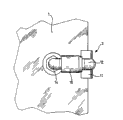
-Fig. 2 shows the phantom drawing of the part of Fig. 1;
-Fig. 3 illustrates the phantom drawing of the present invention's distortion; With
-Fig. 4 illustrates the lateral plan of Fig. 3.
The specific embodiment
In the accompanying drawings, some elements that illustrate can have than the element of reality more large scale or smaller szie, so that should be readily appreciated that accompanying drawing.
Fig. 1 shows curtain wall, is called " astigmatism screen " usually in this field, and it comprises at least one glass plate 1, and this glass plate is used for being lifted on braced structures by at least one fixed system 2 of the present invention.
Among the embodiment shown in Fig. 1, considered that each plate 1 has 4 fixed systems 2, worked at each place, angle of plate respectively.The number and the space that should be understood that fixed system onboard are to change according to the building function of expecting.
For the large span that comprises a large amount of stacked glass plates the surface of glass door and window is housed, two or more adjacent local connectors can be fixed on by the link with two or more support arms on the described structure.
Accompanying drawing 2 shows the implementation detail of plate in an angle of Fig. 1.
According to the present invention in this case, this plate 1 contact area 4 of being provided with one first contact area 3 and roughly being provided with in the both sides of the axis of symmetry of described plate 1.Described first and second contact areas 3,4 are separately positioned on adjacent narrow 5,6 place of this plate 1, and have an opening portion, thereby allow at least one local connector 7 to pass through.Described in addition contact area is passable, in blind hole or through hole, perhaps passes through otch or outburst area (rough region, groove, protruding pin) or passes through clip-on type linkage, is arranged on the side of plate.
Fixed system 2 comprises two local connectors 7,8 shown in figure 2, and they are provided with in the both sides of the mid-plane of described plate respectively.This mid-plane is roughly parallel to plate surface and vertical with described first and second contact areas 3,4.
Each local connector has U-shaped horse nail shape and the particularly stainless steel enforcement of the most handy metal material.
Each horse spike connector (as the sectional view of Fig. 3) comprises middle body 9,10 and two lateral parts 11,12,13,14.The middle body 9 of each horse spike connector, 10 support first contact area and second contact area 3,4 respectively at the first and second anchor portion places, and each is arranged on each lateral parts 11 of the horse nail shape connector on the same side of plate, 12,13,14 connect by adjusting device 15,16 each other, described adjusting device 15,16 are suitable for making the center of the middle body 9,10 of horse spike fixture or contact area 3,4 close.
In the embodiment show in figure 3, described adjusting device is a tensioning apparatus, this tensioning apparatus comprises screw-nut apparatus, parts as nut for example comprise lasso, be equipped with screw thread on the wall within it, this lasso is slidingly mounted on the side direction part of this horse spike connector, as the parts of threaded end of side direction part of for example comprising of nut of the described second horse spike connector, is positioned at the same side of this plate.
Make local connector approaching each other by this adjusting device 15,16, thereby in the plate region generating compressive stress on anchor portion opposite, the stress that described compressive stress produces during with form anchor on this braced structures is opposite.
Certainly, according to the quality of described plate, constitute the material property of this plate, the stress intensity that is produced can be adjusted the material that constitutes this part connector.Therefore can select plastic material, composite material.
Equally, according to a unshowned distortion in the accompanying drawings, can with the torque limiting device particularly rubbing device be connected to this adjusting device 15,16 places.
In Fig. 3 and 4, show another embodiments of the invention distortion.This distortion is different from the distortion shown in Fig. 2, and be arranged on the edge because one of (this first or second) contact area is not arranged on the outer rim of this plate one is departed from the part.
In addition, in Fig. 4, the local connector that can notice described fixed system 2 directly is not supported at this contact area place but at 17 places, intermediate layer on narrow of this plate.
Intermediary element is a rigid slab, and is preferably transparent, and for example polycarbonate or the hard silicone material that reaches 70-75 by shore hardness D constitutes.
Viscose glue preferably also is transparent, is base with the silicones or the acryhic material of knotting with UV particularly.
Because there is the rigidity intermediary element, so viscose glue can be more pliable and tougher, hardness is lower than intermediary element.Therefore, a kind of jointing material for example shore hardness A of silicones types of material is 30-35, allow to implement effective bonding connection between intermediary element and glass plate, and intermediary element is given this intermediate layer 17 with necessary rigidity.
In case the jointing material sclerosis, this intermediate layer 17 allows the weight of plate to be delivered to fully on the described structure, so and because the rigidity intermediary element does not have the danger of the described layer of former generation crushing.
In the distortion of the embodiment shown in Fig. 3, the contact area that departs from from this plate outer rim comprises sleeve pipe 18, and it is implemented with metal material.The sleeve pipe that supports at the wall place of this contact area can mechanical contact-enhancing zone wall, and therefore born the bigger power that produces by this fixed system.
Distortion does not in addition illustrate in the drawings, and described sleeve pipe 18 is equipped with hinge, so that descend or the thermal expansion of plate descends when this plate is installed and/or in local load's (weight of the snow of deposition) effect, allows the transmission of possible relative motion.
In unshowned embodiment, this hinge comprises the similar articulated system of ball-and-socket joint or other any kind, preferably allows to reach 5 at the motion amplitude angle of each direction and spends.
Fixed system 2 of the present invention provides a kind of scheme of superior performance, and this scheme does not need especially glass plate to be reprocessed, and described contact area is easy to machining.
By selecting favourable transparent material, to form intermediate layer and selectable fixed system, the fixed solution that is obtained has satisfied the maximum transparent aesthetic requirement that the architect proposes often.
Detailed description of the present invention is just just carried out in the special embodiment of curtain wall, but the present invention is not limited thereto.
At last, plate to be fixed can be window glass or entire plate, laminate, and mixed plate, decorative panel, but also can be billboard or such as glass, marmorean natural friable material plate or synthetic materials plate.
Because this fixed system can make two plates connect each other, perhaps at least one plate is connected with a braced structures, and described plate can relatively move each other (pivot, slide) or realize opening function, fastness function.
Claims (26)
1. friable material plate (1) is fixed on the fixed system (2) on the braced structures, comprise at least one localized immobilization part (7 or 8), this localized immobilization part (7 or 8) cooperates with at least one first contact area (3), this first contact area (3) is implemented in this friable material plate, it is characterized in that, described localized immobilization part (7 or 8) is included in this friable material plate (1) and goes up second anchor portion that first anchor portion located at this first contact area (3) and second contact area (4) are located, described first and second anchor portions are on the one hand by at least one adjusting device (15,16) link to each other, this adjusting device (15,16) be used to make described first and second anchor portions respectively against described first and second contact areas (3,4), described on the other hand first and second anchor portions are arranged in the plane of this friable material plate (1).
2. fixed system according to claim 1 (2) is characterized in that, this second contact area (4) is positioned on narrow of this friable material plate (1).
3. according to claim 1 or 2 described fixed systems, it is characterized in that this second contact area (4) is positioned on the side of this friable material plate (1).
4. fixed system according to claim 1 (2) is characterized in that, this second contact area (4) is positioned on this braced structures.
5. according to claim 1 or 2 described fixed systems (2), it is characterized in that this first and second contact area (3,4) is implemented in blind hole.
6. according to claim 1 or 2 described fixed systems (2), it is characterized in that this first and second contact area (3,4) is implemented in through hole.
7. according to claim 1 or 2 described fixed systems (2), it is characterized in that this first and second contact area (3,4) is implemented in otch.
8. according to claim 1 or 2 described fixed systems (2), it is characterized in that this first and second contact area (3,4) is implemented by a plurality of outburst areas.
9. according to claim 1 or 2 described fixed systems (2), it is characterized in that this first and second contact area (3,4) is implemented by clamping.
10. according to claim 1 or 2 described fixed systems (2), it is characterized in that described first and second contact areas (3,4) are gone up in adjacent two sides (5,6) of friable material plate (1) respectively and are provided with.
11. fixed system according to claim 10 (2) is characterized in that, described first and second contact areas (3,4) are provided with in the both sides of the axis of symmetry of friable material plate (1) respectively.
12. according to claim 1 or 2 described fixed systems (2), it is characterized in that, described fixed system comprises two localized immobilization parts (7 or 8), these two localized immobilization parts (7 or 8) are separately positioned on the both sides of the mid-plane that is roughly parallel to friable material plate (1), this mid-plane also is approximately perpendicular to first and second contact areas (3,4).
13. according to claim 1 or 2 described fixed systems (2), it is characterized in that, comprise the rigidity intermediate layer (17) that is arranged between one of one of first or second contact area (3,4) and first or second anchor portion.
14., it is characterized in that described adjusting device (15,16) comprises tensioning apparatus according to claim 1 or 2 described fixed systems (2).
15. fixed system according to claim 14 (2) is characterized in that this tensioning apparatus comprises screw-nut apparatus.
16. fixed system according to claim 14 (2) is characterized in that, this adjusting device (15,16) comprises torque limiting apparatus.
17. according to claim 1 or 2 described fixed systems (2), it is characterized in that, this intermediate layer (17) comprises rigidity intermediary element and jointing material, and this rigidity intermediary element causes keeping by holding capacity the dimensional stability of layer, and this jointing material can be realized bonding connection.
18. fixed system according to claim 17 (2) is characterized in that, the shore hardness D of the material of this intermediary element is 70-75.
19. fixed system according to claim 18 (2) is characterized in that, the material that constitutes intermediary element is selected from transparent material, and it can not influence the attractive in appearance of assembly.
20. fixed system according to claim 19 (2) is characterized in that, described transparent material is polycarbonate or hard silicones.
21. fixed system according to claim 17 (2) is characterized in that, the shore hardness A that this jointing material has is 30-35, and is selected from the silicon resin adhesive that uses with glass usually.
22. fixed system according to claim 17 (2) is characterized in that, this intermediary element is along the axis setting of the mid-plane of this friable material plate (1).
23., it is characterized in that one of first or second contact area (3,4) is provided with sleeve pipe (18) according to claim 1 or 2 described fixed systems (2), this sleeve pipe (18) is passed by localized immobilization part (7 or 8).
24. the application to according to each described fixed system (2) in the claim 1~23 is used for curtain wall or the metope made by the friable material plate.
25. the application to according to each described fixed system (2) in the claim 1~23 is used at least two connections between the friable material plate, described friable material plate can move relative to each other.
26. according to claim 24 or 25 described application, wherein said friable material plate (1) the vertical or inclination of vertical direction relatively, and fixed system (2) is according to each described system among the claim 1-24.
Applications Claiming Priority (2)
| Application Number | Priority Date | Filing Date | Title |
|---|---|---|---|
| FR0207540A FR2841289B1 (en) | 2002-06-19 | 2002-06-19 | SYSTEM FOR FASTENING A PANEL OF FRAGILE MATERIAL |
| FR02/07540 | 2002-06-19 |
Publications (2)
| Publication Number | Publication Date |
|---|---|
| CN1662724A CN1662724A (en) | 2005-08-31 |
| CN100449105C true CN100449105C (en) | 2009-01-07 |
Family
ID=29719856
Family Applications (1)
| Application Number | Title | Priority Date | Filing Date |
|---|---|---|---|
| CNB038143003A Expired - Fee Related CN100449105C (en) | 2002-06-19 | 2003-06-18 | System for fixing a panel made of brittle material |
Country Status (11)
| Country | Link |
|---|---|
| US (1) | US7818930B2 (en) |
| EP (1) | EP1518034B1 (en) |
| JP (2) | JP2005533943A (en) |
| KR (1) | KR101033609B1 (en) |
| CN (1) | CN100449105C (en) |
| AT (1) | ATE474992T1 (en) |
| AU (1) | AU2003267491A1 (en) |
| DE (1) | DE60333456D1 (en) |
| FR (1) | FR2841289B1 (en) |
| PL (1) | PL212492B1 (en) |
| WO (1) | WO2004001171A1 (en) |
Families Citing this family (2)
| Publication number | Priority date | Publication date | Assignee | Title |
|---|---|---|---|---|
| CN103375101A (en) * | 2012-04-25 | 2013-10-30 | 宁波东天智能门窗有限公司 | Connection device for double-layer glass |
| US10672306B1 (en) * | 2016-03-18 | 2020-06-02 | Totally Mod Events, Llc | Modular display assembly and related components and methods of use |
Citations (3)
| Publication number | Priority date | Publication date | Assignee | Title |
|---|---|---|---|---|
| FR1376738A (en) * | 1963-09-19 | 1964-10-31 | Improvements in the attachment of glass plates such as glasses, mirrors and the like | |
| CN87104304A (en) * | 1986-04-28 | 1988-03-02 | 米德兰玻璃公司 | Double-paned window securement |
| DE19816099A1 (en) * | 1998-04-10 | 1999-10-21 | Goetz Metall Anlagen | Connection assembly for use in steel constructions esp. in building construction |
Family Cites Families (26)
| Publication number | Priority date | Publication date | Assignee | Title |
|---|---|---|---|---|
| US222279A (en) * | 1879-12-02 | Improvement in picture-frames | ||
| US412953A (en) * | 1889-10-15 | Mount for photographs | ||
| US1083502A (en) * | 1913-02-05 | 1914-01-06 | Silas C Macdowney | Corner-post joint for plate-glasses. |
| US1454335A (en) * | 1921-03-07 | 1923-05-08 | Prendergast Edward | Repair link for chains |
| US1538338A (en) * | 1921-05-11 | 1925-05-19 | Otto Glass & Mirror Company | Mounting for mirrors and the like |
| US1789740A (en) * | 1930-05-09 | 1931-01-20 | Marshall W Gelette | Automobile registration-plate holder |
| US1938541A (en) * | 1932-04-20 | 1933-12-05 | Trico Products Corp | Rear view mirror mounting |
| US2092411A (en) * | 1936-12-12 | 1937-09-07 | Robert R Abrams | Door clamp |
| FR1077193A (en) * | 1953-03-26 | 1954-11-04 | Cie Reunies Glaces Et Verres | Device for handling, storage and transport of flat sheet glass |
| FR1376444A (en) * | 1963-12-12 | 1964-10-23 | Carrara & Matta Spa | Door hinge hinge device |
| JPS42146Y1 (en) * | 1964-02-03 | 1967-01-06 | ||
| GB1356946A (en) * | 1970-05-27 | 1974-06-19 | Ind Ex Engs Ltd British Ind To | Frame and panel assembly |
| US3936968A (en) * | 1970-06-16 | 1976-02-10 | Gilbert Howard E | Adjustable frame |
| US4028832A (en) * | 1976-05-24 | 1977-06-14 | Celia Wu | Corner hook frame |
| DK141299B (en) * | 1976-10-19 | 1980-02-18 | Joergen Skoubo Johansen | Retaining frame construction for openable glass panels and for permanent retention of non-openable glass panels in building parts. |
| US4282668A (en) * | 1979-11-20 | 1981-08-11 | Product Planning & Development, Inc. | Mounting system and method |
| NL8101131A (en) * | 1981-03-09 | 1982-10-01 | Veldhoen Isolatie Bv | DEVICE FOR ATTACHING FAÇADE PANELS TO A SUPPORTING SUPPORT STRUCTURE. |
| AT377171B (en) * | 1983-05-13 | 1985-02-25 | Heinrich Spilka | BRACKET FOR PARTICULARLY FRAMELESS PICTURES OD. DGL. |
| JPH0433348Y2 (en) * | 1986-08-26 | 1992-08-10 | ||
| JPH044407Y2 (en) * | 1987-02-19 | 1992-02-10 | ||
| US4991328A (en) * | 1989-04-28 | 1991-02-12 | Rousseau Jean Pierre | Structures formed from joined elements |
| DE4223694C2 (en) * | 1992-07-21 | 1994-05-26 | Danz Robert | Construction component for the glazing of buildings |
| BE1009254A3 (en) * | 1995-04-06 | 1997-01-07 | Verre Atel Sal | Device for joining together glazing units suspended by means of point clips |
| DE19514818A1 (en) | 1995-04-21 | 1996-10-24 | Heider Stahl Und Hallenbau Gmb | Building glazing for facade walls |
| FR2739406B1 (en) | 1995-09-29 | 1999-01-08 | Saint Gobain Vitrage | DEVICE FOR FIXING GLAZING ONTO A CARRIER STRUCTURE |
| JP3788531B2 (en) * | 1996-08-28 | 2006-06-21 | 株式会社竹中工務店 | Fixed smoke barrier |
-
2002
- 2002-06-19 FR FR0207540A patent/FR2841289B1/en not_active Expired - Fee Related
-
2003
- 2003-06-18 US US10/516,321 patent/US7818930B2/en not_active Expired - Fee Related
- 2003-06-18 EP EP03748178A patent/EP1518034B1/en not_active Expired - Lifetime
- 2003-06-18 WO PCT/FR2003/001853 patent/WO2004001171A1/en active Application Filing
- 2003-06-18 JP JP2004514939A patent/JP2005533943A/en not_active Withdrawn
- 2003-06-18 CN CNB038143003A patent/CN100449105C/en not_active Expired - Fee Related
- 2003-06-18 AU AU2003267491A patent/AU2003267491A1/en not_active Abandoned
- 2003-06-18 PL PL373902A patent/PL212492B1/en not_active IP Right Cessation
- 2003-06-18 DE DE60333456T patent/DE60333456D1/en not_active Expired - Lifetime
- 2003-06-18 AT AT03748178T patent/ATE474992T1/en active
- 2003-06-18 KR KR1020047020574A patent/KR101033609B1/en not_active IP Right Cessation
-
2011
- 2011-01-04 JP JP2011000249A patent/JP2011064066A/en active Pending
Patent Citations (3)
| Publication number | Priority date | Publication date | Assignee | Title |
|---|---|---|---|---|
| FR1376738A (en) * | 1963-09-19 | 1964-10-31 | Improvements in the attachment of glass plates such as glasses, mirrors and the like | |
| CN87104304A (en) * | 1986-04-28 | 1988-03-02 | 米德兰玻璃公司 | Double-paned window securement |
| DE19816099A1 (en) * | 1998-04-10 | 1999-10-21 | Goetz Metall Anlagen | Connection assembly for use in steel constructions esp. in building construction |
Also Published As
| Publication number | Publication date |
|---|---|
| PL212492B1 (en) | 2012-10-31 |
| KR20050010947A (en) | 2005-01-28 |
| JP2005533943A (en) | 2005-11-10 |
| DE60333456D1 (en) | 2010-09-02 |
| WO2004001171A1 (en) | 2003-12-31 |
| PL373902A1 (en) | 2005-09-19 |
| EP1518034B1 (en) | 2010-07-21 |
| FR2841289A1 (en) | 2003-12-26 |
| ATE474992T1 (en) | 2010-08-15 |
| KR101033609B1 (en) | 2011-05-11 |
| FR2841289B1 (en) | 2005-12-23 |
| JP2011064066A (en) | 2011-03-31 |
| US20050284066A1 (en) | 2005-12-29 |
| US7818930B2 (en) | 2010-10-26 |
| CN1662724A (en) | 2005-08-31 |
| EP1518034A1 (en) | 2005-03-30 |
| AU2003267491A1 (en) | 2004-01-06 |
Similar Documents
| Publication | Publication Date | Title |
|---|---|---|
| US5079798A (en) | Glass hinge assembly | |
| US20040140464A1 (en) | Configurable fence and gate systems | |
| US4958807A (en) | Decorative posts for crowd control | |
| CA2377799A1 (en) | Panel and fastening system for panels | |
| PL371350A1 (en) | Panelling with edging and laying aid | |
| AU2002225337B2 (en) | Undercut anchoring element for fixing plates and/or tiles | |
| ATE508700T1 (en) | MULTIAXIAL ANCHOR ARRANGEMENTS FOR SPINE IMPLANTS | |
| US20040206946A1 (en) | Gate post threaded insert | |
| CN101124376A (en) | Retaining device for connecting components, in particular sheathing panels | |
| CN100449105C (en) | System for fixing a panel made of brittle material | |
| KR200493250Y1 (en) | A clamp structure for upper plate fixing of soundproofing tunnel | |
| EP1891282A1 (en) | Support structure and profile rail therefore | |
| AU4100400A (en) | A mounting and hinge fitting for a panel and a panel system comprising such fittings | |
| WO2006109345A8 (en) | Fixing device to bearing structures for the support of panels e.g. in glass, marble or similar, with punctiform anchorage and spherical joint | |
| JPH0826638B2 (en) | Connecting device for structures such as stone materials | |
| JPH1046785A (en) | Mounting structure for decorative wall panel | |
| CN2525156Y (en) | Lock button type slot solid floor board | |
| US7073756B1 (en) | Recessed support assembly | |
| JPH09273264A (en) | Decorative plate mounting structure and connection metal fitting | |
| JP2004232395A (en) | Panel for bearing wall, and bearing wall | |
| JPH0842105A (en) | Wall decorative material installing metal fitting and wall decorative material installing structure | |
| KR100379833B1 (en) | Bracket For Connecting Support Of Stainless Steel-made Roadway Reflecting Mirror Assembly | |
| KR20040093873A (en) | A Fastening Device of Building Outer Wall Ornamental | |
| JPH04319122A (en) | Clamp metal for concrete part | |
| FR2572758A1 (en) | Assembly for constructing transparent walls |
Legal Events
| Date | Code | Title | Description |
|---|---|---|---|
| C06 | Publication | ||
| PB01 | Publication | ||
| C10 | Entry into substantive examination | ||
| SE01 | Entry into force of request for substantive examination | ||
| C14 | Grant of patent or utility model | ||
| GR01 | Patent grant | ||
| C17 | Cessation of patent right | ||
| CF01 | Termination of patent right due to non-payment of annual fee |
Granted publication date: 20090107 Termination date: 20130618 |