JP3788531B2 - Fixed smoke barrier - Google Patents
Fixed smoke barrier Download PDFInfo
- Publication number
- JP3788531B2 JP3788531B2 JP22708496A JP22708496A JP3788531B2 JP 3788531 B2 JP3788531 B2 JP 3788531B2 JP 22708496 A JP22708496 A JP 22708496A JP 22708496 A JP22708496 A JP 22708496A JP 3788531 B2 JP3788531 B2 JP 3788531B2
- Authority
- JP
- Japan
- Prior art keywords
- panel material
- suspension
- fixed
- plate glass
- bracket
- Prior art date
- Legal status (The legal status is an assumption and is not a legal conclusion. Google has not performed a legal analysis and makes no representation as to the accuracy of the status listed.)
- Expired - Lifetime
Links
Images


Description
【0001】
【発明の属する技術分野】
本発明は、建築物内に設置される固定式防煙壁に関する。
【0002】
【従来の技術】
従来から、建築基準法で規定される劇場やホテルなどの特定建築物では、延べ床面積500m2毎に防煙区画を設け、排煙口を設けなければならない。室内を間仕切りなどの壁面で区画できる場合には必要ないが、室内を連続した大空間とする場合には、一般的には、天井壁面より下方に50cm以上突き出した防煙壁(防煙垂れ壁ともいう)で区画する必要がある。
【0003】
防煙壁としては、空間の連続性及び不燃材である必要性の観点から板ガラス製の固定式防煙壁(以下、単に防煙壁ともいう)が多用されている。現在は、煙感知器と連動した可動式防煙壁も商品化されているが、経済性の点から敬遠され、特殊な用途以外は用いられていないのが実状である。
【0004】
板ガラス製の固定式防煙壁の一般的な構成は、天井下地工事直後に、天井下地をなす野縁に金属製のハンガーを用いて金属製のフレームを取り付けるものである。金属製のフレームにはアルミニウム合金製押出し品又は金属製曲げ加工品を用いることが多い。金属製のフレームの取り付け後、天井ボード工事が行われ、パネル材としての板ガラスの取り付け工事となる。
【0005】
板ガラスの取り付け工事は、まず、金属製のフレームに吊り金具をセットすることから始まる。取り付け方法はメーカーによって若干の差が認められる。タップ加工された部品をフレーム内の溝にセットし、その部品にネジ加工された吊り金物を装着する方法や、上部の吊り元を施工時に90度回転することで固定する方法も知られている。
【0006】
板ガラスは、こうして取り付けられた吊り金具に自重で支持される。例えば、吊り金具の下端部は板ガラスを保持するための溝部を有する略U字形状をしており、上枠と下枠に溝を有する枠を用い、板ガラスなどのパネル材の上側をまず上枠の溝に嵌め込み、次にパネル材の下側を下枠の溝に嵌め落として建て込むケンドン方式で取り付けられている。
【0007】
上部のフレームと板ガラスとの隙間には、煙が逃げないように、防煙ゴム又はシーリング材が施工される。同様に板ガラスと板ガラスの間の目地部にもシーリング材が施工される。
【0008】
こうした防煙壁は端部では必ず建築壁面と接することになるが、一般部(中央部)と同様に吊り金具を設け、板ガラスと吊り金具の間隙部及び吊り金具と壁面との隙間部にはシーリングをすることが一般的であった。
【0009】
図9〜13は従来例を示す。断面略コ字状の野縁10と呼ばれる部材が格子状に組み合わされて天井下地が構成されている。野縁10に対して、ハンガー92と蝶ネジ93で吊りボルト9を固定する。この吊りボルト9と固定ナット91でフレーム4を取り付ける。フレーム4の寸法が不足する場合は、フレーム繋ぎ材41と繋ぎ用ビス42でフレームを連結する。次に、吊り金具2をフレーム4の下部から挿入し、90度回転させることで吊り金具2をフレーム4に固定する。
【0010】
パネル材としての板ガラス1を吊る吊り金具2は、フレーム4に取り付けられる吊り元25と、板ガラス1を保持するために断面が略U字形状をしている受け金具としてのガラス受け金具21と、両者をつなぐ金属製の棒状連結部27の3部品で構成されている。棒状連結部27は下端部に雄ネジ部29を有し、また雄ネジ部29にネジ止めされている袋ナット状部材28を有する。ガラス受け金具21は袋ナット状部材28に取り付けられている。
【0011】
ケンドン方式で、板ガラス1を吊り金具2の下部のガラス受け金具21に乗せてセットする。フレーム4と板ガラス1との間には、防煙ゴム5又はシーリング材が施工される。同様に、板ガラス1と板ガラス1との間の目地も弾性のシーリング材11が施工される。板ガラスがセットされた後、化粧カバー6をはめ込んで工事完了となる。
【0012】
壁面端部には、一方向のみにガラス受け金具を有する端部吊り金具3がセットされ、板ガラス1と端部吊り金具3との間隙及び端部吊り金具3と壁面(図示を省略)との目地部にも弾性のシーリング材(図示を省略)が施工される。
【0013】
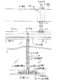
図14に示すように、壁面端部においては施工を容易にするためにガラス自重を支持するための吊り金具を用いず、壁面取り付け型である端部L型金物12を壁8の壁面側にビスなどを用いて取り付けて、端部L型金物12により板ガラス1の下部を支持し、間隙部を弾性のシーリング材で施工する構法が採用されている。
【0014】
かかる固定式防煙壁は、火災時の煙の流れを一時的に遮り避難するための時間を作るためのものであり、その地震時の耐震性に関してはあまり検討されていなかった。
【0015】
阪神大震災を契機としてその耐震性の見直しを実施したところ、地震時に最も破損しやすいのは壁面と接する防煙壁の端部であることがわかったが、その理由は、板ガラスが壁面と接する部分では、地震時に建築物が変形して生じる層間変位の影響が顕著であるためと推測される。
【0016】
防煙壁を設置するにあたり、従来は面外方向の地震力に対しては全く配慮していなかったが、防煙壁は、天井面のフレームを取り付けフレームから吊り金具で板ガラスを支持するものなので、面外方向の地震力を受けると板ガラスは吊り金具の吊り元を中心として振り子状の回転運動を起こす。
【0017】
壁面と接する部分では、壁面側に固定された略L字型の板ガラス取り付け部品にガラスを支持する場合もあるが、この場合は、通常の部分は天井から吊り下げられているため天井と同じ動きとなり、一方、略L字型の板ガラス取り付け部品は、壁面に固定されているので壁面と同じ動きとなる。天井は床スラブから吊り下げられた構造であるため、壁面部との動きは当然異なる。したがって、端部の板ガラスでは、天井の動きと壁面の動きの違いを直接受け、かつ、振り子状運動を拘束されるので、応力が発生し、板ガラスの許容応力を超えた場合、板ガラスが破損する危険性が大きかった。
【0018】
【発明が解決しようとする課題】
前述の板ガラスが破損しやすい問題を回避するためには、壁面端部のディテールの修正が必要であり、壁面端部においても必ず天井側から吊り下げる施工方法をとり、弾性緩衝材を介して端部と壁面との縁を切ることが重要となる。
【0019】
壁面と板ガラス端面との界面を直接シーリング材で施工することは、壁面の影響を少なからず受けることになり、振り子状運動を拘束することにもなるので、避ける方がよい。
【0020】
面外方向に地震力・加速度により板ガラスにどの程度の応力が発生するのかについては、建築物の固有特性、地盤特性や、支持方法などの影響もあり明確ではないが、板ガラスと壁面とが接する部分に強い力が加わることが想定されるので、受け金具部も面外力に対して機能するように弾性体を設置し、板ガラスに与える応力の低減を図ることが必要である。
【0021】
以上述べたように、本発明は、耐震性能に優れた固定式防煙壁の提供を目的とする。
【0022】
【課題を解決するための手段】
本発明は、複数枚のパネル材が天井面の下方に連続して突出するようにして取り付けられて防煙壁が形成されてなる固定式防煙壁において、固定式防煙壁がその平面形状において、略L字型、略T字型、又は略十字型のコーナー部を形成し、防煙壁面の側端部に配されたパネル材は、建築物の壁面に固定せずに前記パネル材と建築物の壁面との間隙に弾性緩衝材を介在させて前記パネル材と建築物の壁面とを当接状態となし、パネル材はパネル材の上端部に設けられたフレームにより支持されていて、かつ、側端部に配されたパネル材はパネル材の側端面部と壁面との間の目地部に位置しフレームに固定されている略L字型の端部吊り金具によりパネル材の下端部が支持され、中央部に配されたパネル材は隣り合うパネル材の目地部に位置しフレームに固定されている略T字型の中央部吊り金具によりパネル材の下端部が支持されてなり、前記コーナー部をなす板ガラス製パネル材とこれに隣接する板ガラス製パネル材との間には、中央部吊り金具のかわりに、左右一対の片側吊り支持方式吊り金具からなる二股構造吊り金具が設けられ、片側吊り支持方式吊り金具はそれぞれ面外方向への回転が可能であることを特徴とする固定式防煙壁を提供する。
【0023】
【発明の実施の形態】
パネル材はパネル材の上端部に設けられたフレームにより支持されていて、かつ、側端部に配されたパネル材はパネル材の側端面部と壁面との間の目地部に位置しフレームに固定されている略L字型の端部吊り金具によりパネル材の下端部が支持され、中央部に配されたパネル材は隣り合うパネル材の目地部に位置しフレームに固定されている略T字型の中央部吊り金具によりパネル材の下端部が支持されていることが好ましい。パネル材としては、線入り板ガラスや網入り板ガラスなどの板ガラスが好適に用いられる。以下、パネル材として板ガラスを例にとって説明する。
【0024】
弾性緩衝材は、例えば、単なるゴム成形体、発泡部を有するゴム成形体、芯部もしくは周辺内部に中空部を有するゴム成形体、又はこれらを組合せてなるゴム成形体が最適である。
【0025】
端部吊り金具及び中央部吊り金具は、例えば、吊り元と棒状連結部と受け金具よりなっていて、受け金具はパネル材を支持するための溝部を有しており、溝部がパネル材と接する部分には敷きゴムと側端部保護ゴムとが設けられ、棒状連結部は袋ナット状部材を有しており、袋ナット状部材がパネル材と接する部分には側部保護ゴムが設けられている。
【0026】
固定式防煙壁がその平面形状において、略L字型、略T字型、又は略十字型のコーナー部を形成するとき、該コーナー部をなす板ガラス製パネル材とこれに隣接する板ガラス製パネル材との間には、中央部吊り金具のかわりに、左右一対の片側吊り支持方式吊り金具からなる二股構造吊り金具が設けられ、片側吊り支持方式吊り金具はそれぞれ面外方向への回転が可能であることが好ましい。
【0027】
前述の面外方向の加速度の影響により生じる板ガラスの発生応力を軽減するために、前記吊り金具は、その板ガラス受け金具に板ガラスを支持するための溝部を有しており、板ガラスと接する前記溝部の下部及び両側面部に弾性ゴム部を有していることがより好ましい。
【0028】
防煙壁面の側端部に配された板ガラスは、直接建築物の壁面に固定せずに前記板ガラスと建築物の壁面との間隙に弾性緩衝材を介在させ、前記板ガラスと建築物の壁面とを弾性緩衝材を介し当接状態とされているので、建築物の壁面と当接する板ガラスの端部に設けられた弾性緩衝材は、層間変位を吸収するとともに、建築物の壁面に生じた面外力が板ガラスに伝達されるのを防止できる。
【0029】
板ガラス間に設けられた吊り金具の板ガラスを支持する略U字型の溝内部側面に設けられる弾性緩衝材は、面外力によって板ガラスが振り子状の回転運動をした際、受け金具と板ガラスが直接的に接触することを防止し、板ガラスが破損することを防ぐ。
【0030】
また、板ガラスが連続して防煙壁を構成する場合、建築物の平面計画に応じて、防煙壁が平面形状で略L字型、略T字型、略十字型を形成する場合もあるが、こうしたコーナー部では、それぞれの方向からの板ガラスの面外方向の振り子状運動を可能とはできない。
【0031】
本発明では、コーナー部の板ガラスは振り子状回転運動を起こさないが、コーナー部と隣接する板ガラスとの目地部で、それぞれの板ガラスを別々に吊り、かつ、両者を弾性ゴム成形体又は非接着の弾性シーリング材等の弾性緩衝材で施工することで、直線状の防煙壁部分は振り子状運動を可能としている。
【0032】
【実施例】
[第1実施例]
図1、図2及び図4により、本発明の固定式防煙壁の第1実施例の側端部を説明する。天井下地の部分の施工から吊りボルトの部分の施工までの構成は従来技術と同様である。
【0033】
本実施例においては端部吊り金具3に、弾性緩衝材としての端部ガスケット7を嵌合させて壁面と縁を切る構成となっている。ガラス受け金具21の内部には敷きゴム22と側部保護ゴム24とを、袋ナット状部材28には側端部保護ゴム23を、設けている。
【0034】
端部ガスケット7の幅寸法Dは、設計条件の層間変位量によるが、大きければ、性能上好ましいが意匠性が低下するので、10〜30cm程度が好適である。
【0035】
端部ガスケット7は、壁面の不陸や地震による層間変位を容易に吸収するため、壁面側に発泡部73を、中央部に中空部72を、板ガラス側にソリッド部71を有する構造のゴム成形体となっている。
【0036】
ソリッド部71には、ソリッド部の端面に板ガラス1の側部を挟持するための断面略コ字形状部75が、ソリッド部71の中央部には棒状連結部27が貫通する貫通孔形成部77が、また断面略コ字形状部75と貫通孔形成部77の間にはスリット76が施され、端部吊り金具3が嵌合されている。中空部72の下端部はシーリング材74で塞がれている。
【0037】
端部吊り金具3は、ガラス受け金具21の端部に棒状連結部27の下端が接続されていて、棒状連結部27の片側で板ガラス1を吊り支持しており、片側吊り支持方式である。
【0038】
図3及び図4により、本発明の固定式防煙壁の第1実施例の中央部を説明する。天井下地の部分の施工から吊りボルトの部分の施工までの構成は従来技術と同様である。
【0039】
本実施例においては、ガラス受け金具21の内部には、板ガラス1とガラス受け金具21とが直接ぶつかることを防止するための敷きゴム22と、板ガラス1の面内方向に板ガラス1と袋ナット状部材28とが直接ぶつかることを防止するために、棒状連結部27の袋ナット状部材28を巻いている側端部保護ゴム23と、板ガラス1の面外方向に板ガラス1とガラス受け金具21とが直接ぶつかることを防止するための側部保護ゴム24とを設けている。
【0040】
吊り金具(中央部吊り金具)2は、ガラス受け金具21の中央に棒状連結部27の下端が接続されていて、棒状連結部27の両側で板ガラス1、1を吊り支持しており、両側吊り支持方式である。
【0041】
[第2実施例]
図5〜図8により、本発明の固定式防煙壁をコーナー部に用いてある第2実施例を説明する。天井下地の部分の施工から吊りボルトの部分の施工までの構成は、第1実施例と同じく従来技術と同様である。
【0042】
建築物の平面計画によっては、防煙壁が一直線状になるとは限らず、略L字型に折れ曲がったり、略T字型、略十字型に交差したりする場合も多い。こうした部分は、一般にコーナー部と呼ばれている。
【0043】
コーナー部では、板ガラスが、それぞれの面外方向に動きが異なるため、振り子状運動を可能とすれば、相互がぶつかって破損する心配もある。逆に、板ガラスを全て拘束してしまえば、拘束による応力が発生する心配がある。
【0044】
本発明では、こうした点を考慮し、コーナー部の板ガラス1と隣接する板ガラス1との間を二股構造吊り金具14で施工することとしている。図7、8で地震時の動きを概念的に示してある。
【0045】
二股構造吊り金具14は、左右一対の吊り金具13、13よりなる。吊り金具13は、ガラス受け金具21の端部に棒状連結部27の下端が接続されていて、棒状連結部27の片側で板ガラス1を吊り支持しており、片側吊り支持方式である。棒状連結部27のほぼ全長部分を被覆するように中間ガスケット26が設けられている。中間ガスケット26は、その断面のほぼ中央に棒状連結部27が貫通する貫通孔形成部261と、棒状連結部27を嵌め込むためのスリット262とを有する。
【0046】
地震力を受けた際、二股構造吊り金具14は、左右の吊り金具13、13が独立して回転が可能である。板ガラス目地部は、それぞれ別々のゴム製の中間ガスケット26、26からなる弾性緩衝材でカバーしているが、非接着の弾性シーリング材からなる弾性緩衝材を棒状連結部にそれぞれ被覆するようにしてもよい。
【0047】
また、左右の吊り金具13、13の周囲を一体的に弾性シーリング材で施工して、弾性シーリング材が硬化後に、左右の吊り金具13、13の中央部で弾性シーリング材を切断することにより、左右の吊り金具13、13が独立して回転可能なようにしてもよい。
【0048】
二股構造吊り金具14を用いることで、コーナー部16と一般直線部17との縁を切ることが可能となる。
【0049】
コーナー部16の板ガラス1と隣接する板ガラス1との間を二股構造吊り金具14を用い、壁面部に端部ガスケット7を用いることにより、一般直線部17については、両端部の拘束がないので面外力を受けた際振り子状の運動を起こす。一方、コーナー部16は独立しているので、一般直線部17の影響は受けない。コーナー部16の板ガラス1だけでは複雑な変形モードは生じないので、板ガラス1が破損することはない。
【0050】
実大での層間変形の実験を行ったところ、従来の構成では、層間変形角1/150での板ガラス下端発生応力は96kg/cm2の許容応力が測定され、層間変形角1/100での板ガラス下端発生応力は186kg/cm2であり、線入り板ガラスのエッジ許容応力100kg/cm2を大きく上回る応力が測定されている。
【0051】
一方、幅25cmの端部ガスケットを用いた実験では、層間変形角1/150で最大発生応力5kg/cm2であり、層間変形角1/100においても最大発生応力10kg/cm2であった。
【0052】
面外変形の試験に関しては、幅1200mm×高さ500mmの板ガラス4枚を施工し、中央部の吊り金具をロープを用いて面外方向に強制的に変形させた。
【0053】
従来の板ガラス端部をシーリングした仕様では、250mm程度変形させた時点で板ガラスにクラックが発生した。一方、本発明のガスケットを用いたものでは、約400mmまで変形させても板ガラスのクラックなどは生じなかった。
【0054】
コンピュータを用いた過渡応答解析では、本発明の効果は顕著であった。まず、固有振動数に関しては、従来技術が3.54Hz、本発明による場合1.81Hzであり、周期が長くなっている。
【0055】
また、本発明では、面外方向への振り子状運動による変位は、従来技術と比較して大きいが、板ガラスに発生する応力は小さいことが確認されている。
【0056】
鉄筋コンクリート構造7階建てのビルに防煙壁が施工されている状態をモデル化し、米国のカリフォルニアで発生した”EL CENTRO”の地震波を水平方向に入力した解析を行った。入力地震波は255ガルであるが、7階部の防煙壁が施工される屋上階床の応答加速度は731ガルとなっている。
【0057】
この加速度を、従来仕様と本発明仕様とにそれぞれ入力して、過渡応答解析を実施した。最大変位は、従来仕様で19cm、本発明の仕様で21cmであった。最大発生応力は、従来仕様で580kg/cm2、本発明の仕様で35kg/cm2であった。このように本発明の効果は顕著である。
【0058】
また、二股構造吊り金具により、平面形状が様々な場合においても耐震性を大幅に向上させることが可能となった。
【0059】
【発明の効果】
本発明の構成によれば、固定式防煙壁の耐震性を大幅に向上させうる。特に、壁面と接する端部には端部ガスケットからなる弾性緩衝材を用いることにより、壁面の不陸を吸収するとともに、地震時の層間変位を吸収して板ガラスの破損を防止できる。
【0060】
また、固定式防煙壁がコーナー部を有する場合においても、二股構造吊り金具を用いることにより、地震時の層間変位を吸収して板ガラスの破損を防止できる。
【0061】
また、ガラス受け金具に敷きゴムと側端部保護ゴムと側部保護ゴムとを用いることにより、地震時に板ガラスとそれを吊り支持する吊り金具とのぶつかりによる板ガラスの破損をより大きく防止できる。
【図面の簡単な説明】
【図1】本発明の固定式防煙壁の第1実施例において側端部の正面図。
【図2】図1の固定式防煙壁の断面図であって、(a)はA−A線に沿った断面図、(b)はB−B線に沿った断面図。
【図3】本発明の固定式防煙壁の第1実施例において一部を切り欠いた中央部の正面図。
【図4】本発明の固定式防煙壁の第1実施例に用いられる主要部品の分解斜視図。
【図5】図7の固定式防煙壁の一部を切り欠いた要部正面図。
【図6】図5の固定式防煙壁においてC−C線に沿った断面図。
【図7】本発明の固定式防煙壁の第2実施例の斜視図。
【図8】図7の固定式防煙壁の平面図。
【図9】固定式防煙壁の第1従来例の一部を切り欠いた斜視図。
【図10】図9の固定式防煙壁の化粧カバーを省略した要部断面図。
【図11】図9の固定式防煙壁の要部断面図。
【図12】図9の固定式防煙壁の主要部の斜視図。
【図13】図9の固定式防煙壁の一部を切り欠いた中央部の正面図。
【図14】固定式防煙壁の第2従来例の一部を切り欠いた側壁部の正面図。
【符号の説明】
1:板ガラス(パネル材)
2、13、15:吊り金具
3:端部吊り金具
4:フレーム
5:防煙ゴム
6:化粧カバー
7:端部ガスケット(弾性緩衝材)
8:壁
9:吊りボルト
10:野縁
11、74:シーリング材
12:端部L字型金物
14:二股構造吊り金具
16:コーナー部
17:一般直線部
18:天井面
21:ガラス受け金具(受け金具)
22:敷きゴム
23:側端部保護ゴム
24:側部保護ゴム
25:吊り元
26:中間ガスケット
27:棒状連結部
28:袋ナット状部材
29:雄ネジ部
41:フレーム繋ぎ材
42:繋ぎ用ビス
61:化粧カバー繋ぎ材
62:繋ぎ用ビス
71:ソリッド部
72:中空部
73:発泡部
75:断面略コ字形状部
76、262:スリット
77、251:貫通孔形成部
91:固定ナット
92:ハンガー
93:蝶ネジ
D:端部ガスケットの幅寸法[0001]
BACKGROUND OF THE INVENTION
The present invention relates to a fixed smoke barrier installed in a building.
[0002]
[Prior art]
Conventionally, in a specific building such as a theater or a hotel stipulated by the Building Standard Law, a smoke-proof section must be provided for every 500 m 2 of the total floor area, and a smoke outlet must be provided. This is not necessary when the room can be partitioned by wall surfaces such as partitions. However, when the room is a continuous large space, generally a smoke barrier (smoke proof wall) protruding 50 cm or more below the ceiling wall surface. (Also called)
[0003]
As the smoke barrier, a plate-type fixed smoke barrier (hereinafter also simply referred to as a smoke barrier) is frequently used from the viewpoint of the continuity of the space and the necessity of being a non-combustible material. At present, movable smoke barriers linked with smoke detectors are also commercialized, but they are shunned from the point of view of economy and are not used except for special purposes.
[0004]
A general configuration of a fixed smoke barrier made of plate glass is that a metal frame is attached to a field edge forming a ceiling base immediately after the ceiling base work using a metal hanger. For the metal frame, an aluminum alloy extruded product or a metal bending product is often used. After installing the metal frame, ceiling board work is performed, and plate glass as panel material is installed.
[0005]
The installation work of the plate glass begins with setting the hanging bracket on the metal frame. There are some differences in the mounting method depending on the manufacturer. There are also known a method of setting a tapped part in a groove in the frame and mounting a hanging hardware screwed on the part, and a method of fixing the upper suspension base by rotating 90 degrees during construction. .
[0006]
The plate glass is supported by its own weight on the hanging metal fitting thus attached. For example, the lower end portion of the hanging metal fitting has a substantially U shape having a groove portion for holding a plate glass, and a frame having a groove in the upper frame and the lower frame is used. It is attached by the Kendon system, which fits into the groove of the frame, and then builds with the lower side of the panel material fitted into the groove of the lower frame.
[0007]
Smoke-proof rubber or a sealing material is applied to the gap between the upper frame and the plate glass so that smoke does not escape. Similarly, a sealing material is also applied to the joint between the plate glasses.
[0008]
These smoke barriers are always in contact with the building wall at the end, but as with the general part (center part), suspension brackets are provided, and the gap between the plate glass and the suspension bracket and the gap between the suspension bracket and the wall surface are provided. Sealing was common.
[0009]
9 to 13 show conventional examples. A member called a
[0010]
A hanging metal fitting 2 for hanging the
[0011]
The
[0012]
An end suspension fitting 3 having a glass catch in only one direction is set at the wall end, and the gap between the
[0013]
As shown in FIG. 14, the end L-shaped metal fitting 12, which is a wall-mounted type, is used on the wall surface side of the
[0014]
Such a fixed smoke barrier is intended to make time for evacuation by temporarily blocking the flow of smoke at the time of fire, and the earthquake resistance during the earthquake has not been studied much.
[0015]
After reviewing the seismic resistance of the Great Hanshin Earthquake, it was found that the end of the smoke barrier that touches the wall surface is the most easily damaged during the earthquake. In this case, it is presumed that the influence of the interlayer displacement caused by the deformation of the building during the earthquake is significant.
[0016]
Conventionally, when installing smoke barriers, no consideration was given to out-of-plane seismic forces. However, smoke barriers attach a frame on the ceiling surface and support plate glass from the frame with suspension brackets. When receiving an earthquake force in the out-of-plane direction, the plate glass causes a pendulum-like rotational movement around the suspension bracket.
[0017]
In the part in contact with the wall surface, the glass may be supported by a substantially L-shaped plate glass mounting part fixed to the wall surface side, but in this case, the normal part is suspended from the ceiling, so the same movement as the ceiling On the other hand, since the substantially L-shaped plate glass attachment component is fixed to the wall surface, it moves in the same manner as the wall surface. Since the ceiling is a structure suspended from the floor slab, the movement with the wall surface portion is naturally different. Therefore, in the plate glass at the end, the difference between the movement of the ceiling and the wall surface is directly received and the pendulum-like movement is constrained, so stress is generated, and if the allowable stress of the plate glass is exceeded, the plate glass is damaged. The danger was great.
[0018]
[Problems to be solved by the invention]
In order to avoid the above-mentioned problem that the plate glass is easily damaged, it is necessary to correct the details of the wall end, and the wall end must be hung from the ceiling side. It is important to cut the edge between the part and the wall surface.
[0019]
It is better to avoid constructing the interface between the wall surface and the end face of the glass sheet directly with a sealing material, because it will be affected by the wall surface and restrain the pendulum motion.
[0020]
It is not clear how much stress is generated on the glass sheet due to the seismic force / acceleration in the out-of-plane direction, due to the influence of the inherent characteristics of the building, the ground characteristics, the support method, etc., but the glass sheet contacts the wall surface. Since it is assumed that a strong force is applied to the portion, it is necessary to reduce the stress applied to the plate glass by installing an elastic body so that the receiving metal portion also functions against the out-of-plane force.
[0021]
As described above, an object of the present invention is to provide a fixed smoke barrier excellent in earthquake resistance.
[0022]
[Means for Solving the Problems]
The present invention relates to a fixed smoke barrier wall in which a plurality of panel members are attached so as to continuously protrude below the ceiling surface to form a smoke barrier wall, and the fixed smoke barrier wall has a planar shape. The panel material which forms a substantially L-shaped, substantially T-shaped or substantially cross-shaped corner portion and is arranged on the side end portion of the smoke-proof wall surface is not fixed to the wall surface of the building. The panel material and the wall surface of the building are in contact with each other by interposing an elastic cushioning material between the wall surface of the building and the wall surface of the building, and the panel material is supported by a frame provided at the upper end of the panel material. In addition, the panel material arranged at the side end is positioned at the joint between the side end surface and the wall surface of the panel material and is fixed to the frame by a substantially L-shaped end hanging bracket. The panel material placed in the center is located at the joint of adjacent panel materials. The lower end portion of the panel material is supported by a substantially T-shaped central hanging bracket fixed to the frame, and between the plate glass panel material forming the corner portion and the plate glass panel material adjacent thereto, Instead of the central suspension bracket, a bifurcated suspension bracket consisting of a pair of left and right single-side suspension support type suspension brackets is provided, and each of the single-side suspension support type suspension brackets can be rotated in the out-of-plane direction. Provide a fixed smoke barrier.
[0023]
DETAILED DESCRIPTION OF THE INVENTION
The panel material is supported by a frame provided at the upper end portion of the panel material, and the panel material arranged at the side end portion is located at the joint between the side end surface portion and the wall surface of the panel material. The lower end portion of the panel material is supported by the fixed substantially L-shaped end suspension bracket, and the panel material arranged in the central portion is located at the joint portion of the adjacent panel material and is fixed to the frame. It is preferable that the lower end part of the panel material is supported by the letter-shaped central part hanging bracket. As the panel material, plate glass such as wire-containing plate glass or mesh-containing plate glass is preferably used. Hereinafter, a plate glass will be described as an example of the panel material.
[0024]
As the elastic buffer material, for example, a mere rubber molded body, a rubber molded body having a foamed portion, a rubber molded body having a hollow portion in the core portion or the periphery, or a rubber molded body formed by combining these is optimal.
[0025]
The end suspension bracket and the central suspension bracket are composed of, for example, a suspension source, a rod-shaped connecting portion, and a receiving bracket, and the receiving bracket has a groove portion for supporting the panel material, and the groove portion is in contact with the panel material. The part is provided with laying rubber and side end protection rubber, the rod-like connecting part has a cap nut-like member, and the part where the cap nut-like member is in contact with the panel material is provided with side protection rubber Yes.
[0026]
When the fixed smoke-proof wall forms a substantially L-shaped, T-shaped, or substantially cross-shaped corner portion in the planar shape, a plate glass panel material forming the corner portion and a plate glass panel adjacent thereto A bifurcated suspension bracket consisting of a pair of left and right single-side suspension support type suspension brackets is provided in place of the central suspension bracket, and each one-side suspension support type suspension bracket can be rotated in the out-of-plane direction. It is preferable that
[0027]
In order to reduce the generated stress of the plate glass caused by the influence of the acceleration in the out-of-plane direction, the hanging metal fitting has a groove portion for supporting the plate glass on the plate glass receiving metal fitting, and the groove portion in contact with the plate glass It is more preferable to have elastic rubber portions on the lower portion and both side surface portions.
[0028]
The plate glass arranged on the side edge of the smoke-proof wall is not directly fixed to the wall of the building, but an elastic buffer is interposed in the gap between the plate glass and the wall of the building, and the plate glass and the wall of the building The elastic cushioning material provided at the end of the plate glass that abuts against the wall surface of the building absorbs the inter-layer displacement and is the surface generated on the wall surface of the building. It is possible to prevent external force from being transmitted to the glass sheet.
[0029]
The elastic cushioning material provided on the inner side surface of the substantially U-shaped groove that supports the plate glass of the suspension fitting provided between the plate glasses is such that when the plate glass rotates pendulum-like by an out-of-plane force, This prevents contact with the glass and breaks the glass sheet.
[0030]
Moreover, when a plate glass comprises a smoke barrier continuously, according to the plan of a building, a smoke barrier may form a planar shape with a substantially L shape, a substantially T shape, and a substantially cross shape. However, in such a corner portion, the pendulum-like movement in the out-of-plane direction of the plate glass from each direction cannot be made possible.
[0031]
In the present invention, the plate glass in the corner portion does not cause a pendulum-like rotational movement, but each plate glass is hung separately at the joint portion between the corner portion and the adjacent plate glass, and both are formed of an elastic rubber molded body or non-bonded By constructing with an elastic cushioning material such as an elastic sealing material, the straight smoke barrier enables a pendulum-like movement.
[0032]
【Example】
[First embodiment]
The side end portion of the first embodiment of the fixed smoke barrier of the present invention will be described with reference to FIGS. The construction from the construction of the ceiling base part to the construction of the suspension bolt part is the same as in the prior art.
[0033]
In this embodiment, an end gasket 7 as an elastic cushioning material is fitted to the end suspension fitting 3 to cut the wall and the edge. A laying
[0034]
The width dimension D of the end gasket 7 depends on the amount of interlayer displacement in the design conditions, but if it is large, it is preferable in terms of performance, but the design property is lowered, so about 10 to 30 cm is preferable.
[0035]
The end gasket 7 has a structure having a foamed portion 73 on the wall surface side, a hollow portion 72 in the center portion, and a
[0036]
The
[0037]
The end suspension fitting 3 is a one-side suspension support system in which the lower end of the rod-like connecting
[0038]
The center part of the first embodiment of the fixed smoke barrier of the present invention will be described with reference to FIGS. The construction from the construction of the ceiling base part to the construction of the suspension bolt part is the same as in the prior art.
[0039]
In the present embodiment, a
[0040]
The suspension bracket (center suspension bracket) 2 is connected to the lower end of the rod-shaped connecting
[0041]
[Second Embodiment]
A second embodiment in which the fixed smoke barrier of the present invention is used at the corner will be described with reference to FIGS. The construction from the construction of the ceiling base part to the construction of the suspension bolt part is the same as that of the prior art as in the first embodiment.
[0042]
Depending on the plan of the building, the smoke barriers are not always straight, but are often bent into a substantially L shape, or crossed into a substantially T shape or a cross shape. Such a portion is generally called a corner portion.
[0043]
In the corner portion, since the movement of the plate glass is different in each out-of-plane direction, if the pendulum-like movement is possible, there is a concern that they may collide with each other and break. Conversely, if all the plate glass is constrained, there is a concern that stress due to the constraining occurs.
[0044]
In the present invention, in consideration of such points, the fork is provided with a forked
[0045]
The
[0046]
When subjected to seismic force, the
[0047]
In addition, by integrally constructing the periphery of the left and
[0048]
By using the bifurcated
[0049]
By using a bifurcated structure hanging metal fitting 14 between the
[0050]
When an experiment of interlayer deformation at actual size was performed, in the conventional configuration, an allowable stress of 96 kg / cm 2 was measured as the stress generated at the lower end of the sheet glass at an interlayer deformation angle of 1/150. flat glass bottom generated stress is 186 kg / cm 2, greater than the stress of the edge
[0051]
On the other hand, in an experiment using an end gasket having a width of 25 cm, the maximum generated stress was 5 kg / cm 2 at an interlayer deformation angle of 1/150, and the maximum generated stress was 10 kg / cm 2 even at an interlayer deformation angle of 1/100.
[0052]
Regarding the out-of-plane deformation test, four plate glasses having a width of 1200 mm and a height of 500 mm were constructed, and the hanging bracket in the center was forcibly deformed in the out-of-plane direction using a rope.
[0053]
In the conventional specification in which the edge of the glass sheet was sealed, cracks occurred in the glass sheet when it was deformed by about 250 mm. On the other hand, in the case of using the gasket of the present invention, cracks in the plate glass did not occur even when deformed to about 400 mm.
[0054]
In the transient response analysis using a computer, the effect of the present invention was remarkable. First, the natural frequency is 3.54 Hz in the prior art, and 1.81 Hz in the case of the present invention, and the period is long.
[0055]
Moreover, in this invention, although the displacement by the pendulum-like motion to an out-of-plane direction is large compared with a prior art, it is confirmed that the stress which generate | occur | produces in plate glass is small.
[0056]
We modeled the state where smoke barriers were constructed in a 7-story building with reinforced concrete structure, and analyzed the "EL CENTRO" seismic wave generated in California, USA, in the horizontal direction. The input seismic wave is 255 gal, but the response acceleration of the roof floor where the smoke barrier on the 7th floor is constructed is 731 gal.
[0057]
This acceleration was input to the conventional specification and the present invention specification, respectively, and a transient response analysis was performed. The maximum displacement was 19 cm in the conventional specification and 21 cm in the specification of the present invention. The maximum generated stress was 580 kg / cm 2 in the conventional specification and 35 kg / cm 2 in the specification of the present invention. Thus, the effect of the present invention is remarkable.
[0058]
In addition, the bifurcated suspension bracket can greatly improve the earthquake resistance even when the planar shape is various.
[0059]
【The invention's effect】
According to the configuration of the present invention, the earthquake resistance of the fixed smoke barrier can be greatly improved. In particular, by using an elastic cushioning material made of an end gasket at the end portion in contact with the wall surface, it is possible to absorb the unevenness of the wall surface and to absorb the inter-layer displacement at the time of an earthquake and prevent the glass plate from being damaged.
[0060]
Moreover, even when the fixed smoke barrier has a corner portion, by using the bifurcated structure hanging bracket, it is possible to absorb the interlayer displacement at the time of the earthquake and prevent the glass plate from being damaged.
[0061]
Further, by using the rubber, the side edge protection rubber, and the side protection rubber laid on the glass receiving bracket, it is possible to further prevent the sheet glass from being damaged due to the collision between the sheet glass and the hanging bracket that supports the suspension in the event of an earthquake.
[Brief description of the drawings]
FIG. 1 is a front view of a side end portion of a fixed smoke barrier according to a first embodiment of the present invention.
2 is a cross-sectional view of the fixed smoke barrier of FIG. 1, wherein (a) is a cross-sectional view taken along the line AA, and (b) is a cross-sectional view taken along the line BB.
FIG. 3 is a front view of the central portion of the first embodiment of the fixed smoke barrier of the present invention, with a part cut away.
FIG. 4 is an exploded perspective view of main components used in the first embodiment of the fixed smoke barrier of the present invention.
FIG. 5 is a front view of a principal part in which a part of the fixed smoke barrier shown in FIG. 7 is cut away;
6 is a cross-sectional view taken along the line CC in the fixed smoke barrier of FIG. 5;
FIG. 7 is a perspective view of a second embodiment of the fixed smoke barrier of the present invention.
8 is a plan view of the fixed smoke barrier shown in FIG.
FIG. 9 is a perspective view in which a part of a first conventional example of a fixed smoke barrier is cut out.
10 is a cross-sectional view of a main part in which a decorative cover of the fixed smoke-proof wall of FIG. 9 is omitted.
11 is a cross-sectional view of a main part of the fixed smoke barrier shown in FIG. 9;
12 is a perspective view of the main part of the fixed smoke barrier of FIG. 9;
13 is a front view of a central portion in which a part of the fixed smoke-proof wall of FIG. 9 is cut away.
FIG. 14 is a front view of a side wall portion in which a part of a second conventional example of a fixed smoke barrier is cut out.
[Explanation of symbols]
1: Flat glass (panel material)
2, 13, 15: Suspension bracket 3: End suspension bracket 4: Frame 5: Smoke-proof rubber 6: Cosmetic cover 7: End gasket (elastic cushioning material)
8: Wall 9: Hanging bolt 10:
22: laying rubber 23: side end protection rubber 24: side part protection rubber 25: suspension source 26: intermediate gasket 27: rod-like connecting part 28: cap nut-like member 29: male screw part 41: frame connecting member 42: for connecting Screw 61: decorative cover connecting material 62: connecting screw 71: solid portion 72: hollow portion 73: foamed portion 75: substantially U-shaped section 76, 262: slit 77, 251: through hole forming portion 91: fixing nut 92 : Hanger 93: Thumbscrew D: Width of end gasket
Claims (4)
Priority Applications (1)
| Application Number | Priority Date | Filing Date | Title |
|---|---|---|---|
| JP22708496A JP3788531B2 (en) | 1996-08-28 | 1996-08-28 | Fixed smoke barrier |
Applications Claiming Priority (1)
| Application Number | Priority Date | Filing Date | Title |
|---|---|---|---|
| JP22708496A JP3788531B2 (en) | 1996-08-28 | 1996-08-28 | Fixed smoke barrier |
Publications (2)
| Publication Number | Publication Date |
|---|---|
| JPH1066737A JPH1066737A (en) | 1998-03-10 |
| JP3788531B2 true JP3788531B2 (en) | 2006-06-21 |
Family
ID=16855260
Family Applications (1)
| Application Number | Title | Priority Date | Filing Date |
|---|---|---|---|
| JP22708496A Expired - Lifetime JP3788531B2 (en) | 1996-08-28 | 1996-08-28 | Fixed smoke barrier |
Country Status (1)
| Country | Link |
|---|---|
| JP (1) | JP3788531B2 (en) |
Families Citing this family (4)
| Publication number | Priority date | Publication date | Assignee | Title |
|---|---|---|---|---|
| FR2841289B1 (en) * | 2002-06-19 | 2005-12-23 | Saint Gobain | SYSTEM FOR FASTENING A PANEL OF FRAGILE MATERIAL |
| JP2006320433A (en) * | 2005-05-17 | 2006-11-30 | Ishii Glass Kogyo:Kk | Plate suspension system |
| JP5952627B2 (en) * | 2012-04-24 | 2016-07-13 | 株式会社森硝子店 | Smoke barrier |
| KR101286188B1 (en) * | 2013-01-21 | 2013-07-15 | 주식회사클레스트라하우저만 | Fire extinguishing auxiliary equipment of intensive air-conditioning booth |
-
1996
- 1996-08-28 JP JP22708496A patent/JP3788531B2/en not_active Expired - Lifetime
Also Published As
| Publication number | Publication date |
|---|---|
| JPH1066737A (en) | 1998-03-10 |
Similar Documents
| Publication | Publication Date | Title |
|---|---|---|
| US11002007B2 (en) | Process for assembling a unitized panel for use within an exterior dynamic curtain wall assembly | |
| JP7282197B2 (en) | Process for assembling fire, smoke, sound and/or waterproofing systems into dynamic curtain wall facades | |
| US11713572B2 (en) | Process for assembling a unitized panel for use within an exterior dynamic curtain wall assembly | |
| JP3788531B2 (en) | Fixed smoke barrier | |
| JPH0440498B2 (en) | ||
| CA3045342A1 (en) | Perimeter fire barrier system | |
| US20230160201A1 (en) | Insulation mounting bracket | |
| JP3750193B2 (en) | Smoke barrier | |
| JP3107717U (en) | Seismic construction of partition walls | |
| RU2720431C1 (en) | Facade for building, facade manufacturing method and construction kit for facade of building | |
| JP3045590U (en) | Seismic isolation glass smoke proof wall | |
| JP5216117B2 (en) | Fireproof wall structure provided in the opening of apartment houses and layout change method | |
| JP7005869B2 (en) | Water stop structure of the building | |
| JPH0326812Y2 (en) | ||
| JP3878472B2 (en) | Seismic structure of joints | |
| JPS60184147A (en) | Outer peripheral wall structure of building | |
| CN116648546A (en) | Curtain Wall Isolation System | |
| JPH0953288A (en) | Mounting construction of curtain wall unit and mullion bearing the curtain wall unit and joint construction of transom | |
| JP4664083B2 (en) | Fire stop structure in the shaft construction method | |
| JP3172133U (en) | Fiberglass smoke screen | |
| JP3352046B2 (en) | Cable rack | |
| JPS6256300B2 (en) | ||
| JP2001303670A (en) | External wall panel and unit building making use thereof | |
| BG121Y1 (en) | Connection between panels | |
| JP2014218854A (en) | Aseismatic ceiling |
Legal Events
| Date | Code | Title | Description |
|---|---|---|---|
| A977 | Report on retrieval |
Free format text: JAPANESE INTERMEDIATE CODE: A971007 Effective date: 20050908 |
|
| A131 | Notification of reasons for refusal |
Free format text: JAPANESE INTERMEDIATE CODE: A131 Effective date: 20050913 |
|
| A521 | Written amendment |
Free format text: JAPANESE INTERMEDIATE CODE: A523 Effective date: 20051102 |
|
| TRDD | Decision of grant or rejection written | ||
| A01 | Written decision to grant a patent or to grant a registration (utility model) |
Free format text: JAPANESE INTERMEDIATE CODE: A01 Effective date: 20060322 |
|
| A61 | First payment of annual fees (during grant procedure) |
Free format text: JAPANESE INTERMEDIATE CODE: A61 Effective date: 20060322 |
|
| R150 | Certificate of patent or registration of utility model |
Free format text: JAPANESE INTERMEDIATE CODE: R150 |
|
| FPAY | Renewal fee payment (event date is renewal date of database) |
Free format text: PAYMENT UNTIL: 20090407 Year of fee payment: 3 |
|
| S111 | Request for change of ownership or part of ownership |
Free format text: JAPANESE INTERMEDIATE CODE: R313117 |
|
| FPAY | Renewal fee payment (event date is renewal date of database) |
Free format text: PAYMENT UNTIL: 20090407 Year of fee payment: 3 |
|
| R350 | Written notification of registration of transfer |
Free format text: JAPANESE INTERMEDIATE CODE: R350 |
|
| FPAY | Renewal fee payment (event date is renewal date of database) |
Free format text: PAYMENT UNTIL: 20090407 Year of fee payment: 3 |
|
| FPAY | Renewal fee payment (event date is renewal date of database) |
Free format text: PAYMENT UNTIL: 20100407 Year of fee payment: 4 |
|
| FPAY | Renewal fee payment (event date is renewal date of database) |
Free format text: PAYMENT UNTIL: 20100407 Year of fee payment: 4 |
|
| FPAY | Renewal fee payment (event date is renewal date of database) |
Free format text: PAYMENT UNTIL: 20110407 Year of fee payment: 5 |
|
| S531 | Written request for registration of change of domicile |
Free format text: JAPANESE INTERMEDIATE CODE: R313531 |
|
| R371 | Transfer withdrawn |
Free format text: JAPANESE INTERMEDIATE CODE: R371 |
|
| FPAY | Renewal fee payment (event date is renewal date of database) |
Free format text: PAYMENT UNTIL: 20120407 Year of fee payment: 6 |
|
| S531 | Written request for registration of change of domicile |
Free format text: JAPANESE INTERMEDIATE CODE: R313531 |
|
| FPAY | Renewal fee payment (event date is renewal date of database) |
Free format text: PAYMENT UNTIL: 20120407 Year of fee payment: 6 |
|
| R350 | Written notification of registration of transfer |
Free format text: JAPANESE INTERMEDIATE CODE: R350 |
|
| FPAY | Renewal fee payment (event date is renewal date of database) |
Free format text: PAYMENT UNTIL: 20130407 Year of fee payment: 7 |
|
| FPAY | Renewal fee payment (event date is renewal date of database) |
Free format text: PAYMENT UNTIL: 20140407 Year of fee payment: 8 |
|
| EXPY | Cancellation because of completion of term |