CN100416177C - Refrigerant cycle apparatus - Google Patents
Refrigerant cycle apparatus Download PDFInfo
- Publication number
- CN100416177C CN100416177C CNB2005100079828A CN200510007982A CN100416177C CN 100416177 C CN100416177 C CN 100416177C CN B2005100079828 A CNB2005100079828 A CN B2005100079828A CN 200510007982 A CN200510007982 A CN 200510007982A CN 100416177 C CN100416177 C CN 100416177C
- Authority
- CN
- China
- Prior art keywords
- cold
- producing medium
- refrigerant
- mentioned
- pressure side
- Prior art date
- Legal status (The legal status is an assumption and is not a legal conclusion. Google has not performed a legal analysis and makes no representation as to the accuracy of the status listed.)
- Expired - Fee Related
Links
Images


Classifications
-
- F—MECHANICAL ENGINEERING; LIGHTING; HEATING; WEAPONS; BLASTING
- F25—REFRIGERATION OR COOLING; COMBINED HEATING AND REFRIGERATION SYSTEMS; HEAT PUMP SYSTEMS; MANUFACTURE OR STORAGE OF ICE; LIQUEFACTION SOLIDIFICATION OF GASES
- F25B—REFRIGERATION MACHINES, PLANTS OR SYSTEMS; COMBINED HEATING AND REFRIGERATION SYSTEMS; HEAT PUMP SYSTEMS
- F25B1/00—Compression machines, plants or systems with non-reversible cycle
-
- F—MECHANICAL ENGINEERING; LIGHTING; HEATING; WEAPONS; BLASTING
- F25—REFRIGERATION OR COOLING; COMBINED HEATING AND REFRIGERATION SYSTEMS; HEAT PUMP SYSTEMS; MANUFACTURE OR STORAGE OF ICE; LIQUEFACTION SOLIDIFICATION OF GASES
- F25B—REFRIGERATION MACHINES, PLANTS OR SYSTEMS; COMBINED HEATING AND REFRIGERATION SYSTEMS; HEAT PUMP SYSTEMS
- F25B9/00—Compression machines, plants or systems, in which the refrigerant is air or other gas of low boiling point
- F25B9/002—Compression machines, plants or systems, in which the refrigerant is air or other gas of low boiling point characterised by the refrigerant
- F25B9/008—Compression machines, plants or systems, in which the refrigerant is air or other gas of low boiling point characterised by the refrigerant the refrigerant being carbon dioxide
-
- F—MECHANICAL ENGINEERING; LIGHTING; HEATING; WEAPONS; BLASTING
- F25—REFRIGERATION OR COOLING; COMBINED HEATING AND REFRIGERATION SYSTEMS; HEAT PUMP SYSTEMS; MANUFACTURE OR STORAGE OF ICE; LIQUEFACTION SOLIDIFICATION OF GASES
- F25B—REFRIGERATION MACHINES, PLANTS OR SYSTEMS; COMBINED HEATING AND REFRIGERATION SYSTEMS; HEAT PUMP SYSTEMS
- F25B1/00—Compression machines, plants or systems with non-reversible cycle
- F25B1/10—Compression machines, plants or systems with non-reversible cycle with multi-stage compression
-
- F—MECHANICAL ENGINEERING; LIGHTING; HEATING; WEAPONS; BLASTING
- F25—REFRIGERATION OR COOLING; COMBINED HEATING AND REFRIGERATION SYSTEMS; HEAT PUMP SYSTEMS; MANUFACTURE OR STORAGE OF ICE; LIQUEFACTION SOLIDIFICATION OF GASES
- F25B—REFRIGERATION MACHINES, PLANTS OR SYSTEMS; COMBINED HEATING AND REFRIGERATION SYSTEMS; HEAT PUMP SYSTEMS
- F25B40/00—Subcoolers, desuperheaters or superheaters
-
- F—MECHANICAL ENGINEERING; LIGHTING; HEATING; WEAPONS; BLASTING
- F25—REFRIGERATION OR COOLING; COMBINED HEATING AND REFRIGERATION SYSTEMS; HEAT PUMP SYSTEMS; MANUFACTURE OR STORAGE OF ICE; LIQUEFACTION SOLIDIFICATION OF GASES
- F25B—REFRIGERATION MACHINES, PLANTS OR SYSTEMS; COMBINED HEATING AND REFRIGERATION SYSTEMS; HEAT PUMP SYSTEMS
- F25B9/00—Compression machines, plants or systems, in which the refrigerant is air or other gas of low boiling point
-
- F—MECHANICAL ENGINEERING; LIGHTING; HEATING; WEAPONS; BLASTING
- F25—REFRIGERATION OR COOLING; COMBINED HEATING AND REFRIGERATION SYSTEMS; HEAT PUMP SYSTEMS; MANUFACTURE OR STORAGE OF ICE; LIQUEFACTION SOLIDIFICATION OF GASES
- F25B—REFRIGERATION MACHINES, PLANTS OR SYSTEMS; COMBINED HEATING AND REFRIGERATION SYSTEMS; HEAT PUMP SYSTEMS
- F25B2309/00—Gas cycle refrigeration machines
- F25B2309/06—Compression machines, plants or systems characterised by the refrigerant being carbon dioxide
- F25B2309/061—Compression machines, plants or systems characterised by the refrigerant being carbon dioxide with cycle highest pressure above the supercritical pressure
-
- F—MECHANICAL ENGINEERING; LIGHTING; HEATING; WEAPONS; BLASTING
- F25—REFRIGERATION OR COOLING; COMBINED HEATING AND REFRIGERATION SYSTEMS; HEAT PUMP SYSTEMS; MANUFACTURE OR STORAGE OF ICE; LIQUEFACTION SOLIDIFICATION OF GASES
- F25B—REFRIGERATION MACHINES, PLANTS OR SYSTEMS; COMBINED HEATING AND REFRIGERATION SYSTEMS; HEAT PUMP SYSTEMS
- F25B2500/00—Problems to be solved
- F25B2500/01—Geometry problems, e.g. for reducing size
-
- F—MECHANICAL ENGINEERING; LIGHTING; HEATING; WEAPONS; BLASTING
- F25—REFRIGERATION OR COOLING; COMBINED HEATING AND REFRIGERATION SYSTEMS; HEAT PUMP SYSTEMS; MANUFACTURE OR STORAGE OF ICE; LIQUEFACTION SOLIDIFICATION OF GASES
- F25B—REFRIGERATION MACHINES, PLANTS OR SYSTEMS; COMBINED HEATING AND REFRIGERATION SYSTEMS; HEAT PUMP SYSTEMS
- F25B31/00—Compressor arrangements
- F25B31/006—Cooling of compressor or motor
Abstract
For a purpose of preventing a compressor (11) from being damaged by liquid compression without disposing any accumulator on a low-pressure side, there is disclosed a transition critical refrigerant cycle apparatus having a supercritical pressure on a high-pressure side. The transition critical refrigerant cycle apparatus constituted by connecting a compressor (11), a gas cooler (12), a pressure reducing device (14), an evaporator (15) and the like in an annular shape, using carbon dioxide as a refrigerant, and capable of having the supercritical pressure on the high-pressure side comprises: an internal heat exchanger (45) for exchanging heat between a refrigerant which has flown out of the gas cooler (12) and a refrigerant which has flown out of the evaporator (15). This internal heat exchanger (45) comprises a high-pressure-side channel (64) through which the refrigerant from the gas cooler (12) flows, and a low-pressure-side channel (66) which is disposed in a heat exchanging manner with this high-pressure-side channel (64) and through which the refrigerant from the evaporator (15) flows, the refrigerant is passed upwards from below in the high-pressure-side channel (64), and the refrigerant is passed downwards from above in the low-pressure-side channel (66).
Description
Technical field
The present invention relates to a kind of compressor, gas cooler, decompressor, evaporimeter etc. are connected into ring-type and constitute, use carbon dioxide as cold-producing medium, can make the high-pressure side is the refrigerant cycle apparatus of supercritical pressure.
Background technology
Existing this refrigerant cycle apparatus connects into ring-type with rotary compressor (compressor), gas cooler, decompressor (expansion valve or capillary etc.) and evaporimeter etc. successively with pipeline, constitutes refrigerant-cycle systems (refrigerant loop).And cold-producing medium gas is drawn into the low-pressure chamber side of cylinder from the inlet hole of the rotation compressing member of rotary compressor, by the action of rotor and blade, compress, become the cold-producing medium gas of HTHP, through tap, discharge anechoic chamber, be discharged to gas cooler from the hyperbaric chamber side.Cold-producing medium gas carries out throttling with the throttling means after this gas cooler heat radiation, supply to evaporimeter.At this, the cold-producing medium evaporation at this moment, by from heat absorption on every side, is brought into play cooling effect.
In recent years, even the device of developing in order to deal with the earth environment problem at this refrigerant-cycle systems, does not use existing fluorine Lyons (Off ロ Application) yet, and is to use the nature cold-producing medium---carbon dioxide (CO
2) as cold-producing medium, the critical (Move of transformation Pro circle that uses the high-pressure side to turn round as supercritical pressure) refrigerant-cycle systems.
At the critical refrigerant cycle apparatus of such transformation, carry out the liquid state compression in the compressor in order to prevent that liquid refrigerant from turning back to, low-pressure side between the suction side of the outlet side of evaporimeter and compressor, set reservoir, for liquid refrigerant being stored in this reservoir, only gas is drawn into the structure in the compressor.And, adjust decompressor, do not make liquid refrigerant in the reservoir turn back to compressor (for example, with reference to Japanese patent gazette special fair 7-18602 number).
But, reservoir is arranged on the low-pressure side of refrigerant-cycle systems, need the loading of considerable cold-producing medium.In addition, reflux, must enlarge the capacity of reservoir, or the choke valve of decompressor is adjusted, cause the refrigerating capacity that space enlargement or evaporimeter 15 are set and reduce in order to prevent liquid.
In addition, in the occasion of using carbon dioxide as the cold-producing medium of relevant refrigerant cycle apparatus, because compression ratio becomes very high, so under the situation such as temperature degree Gao Shi, it is very difficult improving refrigerating capacity outside.
Summary of the invention
The objective of the invention is, in order to solve relevant prior art problem, making the high-pressure side is the critical refrigerant cycle apparatus of transformation of supercritical pressure, in low-pressure side reservoir is not set, and prevents owing to damage appears in compressor compresses liquid.
Refrigerant cycle apparatus of the present invention, be compressor, gas cooler, decompressor, evaporimeter etc. are connected into ring-type and to constitute, use carbon dioxide as cold-producing medium, the high-pressure side can be the critical refrigerant cycle apparatus of the transformation of supercritical pressure, possess the inner heat exchanger that makes cold-producing medium that comes out from gas cooler and the cold-producing medium that comes out from evaporimeter carry out heat exchange, this inner heat exchanger has: from the high-pressure side runner of the flow of refrigerant of gas cooler; Be adapted to this high-pressure side runner heat exchange, come the low-pressure side runner of the flow of refrigerant of flash-pot, cold-producing medium is flowed in the runner of high-pressure side from bottom to top, cold-producing medium is flowed in the low-pressure side runner from the top down.
In addition, refrigerant cycle apparatus of the present invention is in foregoing invention, and inner heat exchanger uses the bimetallic tube that is made of interior pipe and outer tube to make, and constitutes the high-pressure side runner in interior pipe, constitutes the low-pressure side runner between interior pipe and outer tube.
In addition, refrigerant cycle apparatus of the present invention is in foregoing invention, and inner heat exchanger is used by the plywood that constitutes the dual system runner in inside and constituted, with a runner as the high-pressure side runner, with another runner as the low-pressure side runner.
The present invention possesses the inner heat exchanger that makes cold-producing medium that comes out from gas cooler and the cold-producing medium that comes out from evaporimeter carry out heat exchange, because this inner heat exchanger has; High-pressure side runner from the flow of refrigerant of gas cooler; Be adapted to this high-pressure side runner heat exchange, come the low-pressure side runner of the flow of refrigerant of flash-pot, so, can make the temperature decline that enters the cold-producing medium of decompressor from gas cooler by inner heat exchanger, it is poor at the entropy of evaporimeter to enlarge, and improves refrigerating capacity.
Particularly, because cold-producing medium is flowed in the runner of high-pressure side from bottom to top, cold-producing medium is flowed in the low-pressure side runner from the top down, so, in the low occasion of high pressure ratio supercritical pressure, residual refrigerant can be deposited in the high-pressure side runner of inner heat exchanger, when the temperature degree is low outside etc., can reduce flow into the residual refrigerant of low-pressure side, prevent that unsuitable situation such as compressor breakage is in possible trouble.
In addition, owing to constitute inner heat exchanger with bimetallic tube, or be stacked inner heat exchanger, so, can make from the cold-producing medium of gas cooler with come the cold-producing medium of flash-pot to carry out heat exchange reposefully, and, when the temperature degree is low outside etc., also can be without barrier to high-pressure side runner storing refrigerant.
In addition, the objective of the invention is,, make in the refrigerant cycle apparatus, be convenient to improve the refrigerating capacity of evaporimeter in order to solve relevant prior art problem.
Promptly, refrigerant cycle apparatus of the present invention, be with compressor, gas cooler, decompressor, evaporimeters etc. connect into ring-type and constitute, use carbon dioxide as cold-producing medium, the high-pressure side is the refrigerant cycle apparatus of supercritical pressure, possess and make the inner heat exchanger that carries out heat exchange from gas cooler cold-producing medium that comes out and the cold-producing medium that comes out from evaporimeter, the ratio that makes the low voltage section volume in the circulatory system is more than 30% below 50% of whole volumes, and, make the ratio of the low voltage section volume in the inner heat exchanger, relative whole volumes of low voltage section in the circulatory system are more than 5% below 30%.
In addition, refrigerant cycle apparatus of the present invention, be in foregoing invention, compressor possesses the 1st and the 2nd compressing member that is arranged in the closed container, with the 2nd compressing member the cold-producing medium that is compressed, is discharged to the intermediate pressure in the closed container by the 1st compressing member is compressed, discharges, and the ratio that makes the intermediate pressure department volume in the circulatory system is more than 20% below 50% of whole volumes.
In addition, refrigerant cycle apparatus of the present invention is in foregoing invention, possesses to be used for after the cold-producing medium that is discharged to the intermediate pressure in the closed container from the 1st compressing member is cooled off it being drawn into the intermediate cooling loop of the 2nd compressing member.
In the present invention, can make liquid refrigerant in the evaporimeter incomplete evaporation, but with the form of the liquid/gas multi-phase flow of good heat-transfer, turn back to inner heat exchanger from evaporimeter, the raising by effectively utilizing heat-transfer character and latent heat, the sensible heat of cold-producing medium, can reduce the temperature that enters the on high-tension side cold-producing medium of decompressor from gas cooler effectively, can make in the enthalpy difference of evaporimeter greatly, be convenient to improve refrigerating capacity.
Particularly, in the occasion of the compressor of two stage compression types that use the bosom die mould, for example, be more than 20% below 50% of whole volumes owing to make the ratio of the middle splenium volume in the circulatory system that comprises intermediate cooling loop, so, can bring into play above-mentioned effect to greatest extent.
Description of drawings
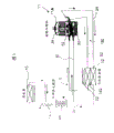
Fig. 1 is the refrigerant loop figure (embodiment 1) of the critical refrigerant cycle apparatus of transformation of one embodiment of the invention.
Fig. 2 is the cut-away view of the inner heat exchanger of Fig. 1.
Fig. 3 is the refrigerant loop figure (embodiment 2) of the refrigerant cycle apparatus of another embodiments of the invention.
Fig. 4 is the p-h curve map of the refrigerant cycle apparatus of Fig. 3.
Fig. 5 is the refrigerant loop figure (embodiment 3) of other embodiment of another refrigerant cycle apparatus of the present invention.
Fig. 6 is the p-h curve map of the refrigerant cycle apparatus of Fig. 5.
The specific embodiment
Below, at length embodiments of the present invention are described according to accompanying drawing.
(embodiment 1)
Fig. 1 is the refrigerant loop figure of the critical refrigerant cycle apparatus of transformation of an embodiment of refrigerant cycle apparatus of the present invention.And the critical refrigerant cycle apparatus of transformation of the present invention is employed devices such as automatic vending machine, air conditioner, freezer or showcase.
In Fig. 1, the 10th, change the refrigerant loop of critical refrigerant cycle apparatus 1, by with compressor 11, gas cooler 12, connect into ring-type as the capillary 14 of decompressor, evaporimeter 15 etc. and constitute.
That is, the refrigerant discharge leader 34 of compressor 11 is connected with the inlet of gas cooler 12.At this, the compressor 11 of embodiment is rotary compressors of bosom pressure 2-stage compression type, by constituting as the electric element 24 of driving element with by the 1st and the 2nd rotation compressing member 50,52 that this electric element 24 drives in closed container 11A.
30 is the cold-producing medium ingress pipes that are used for cold-producing medium is imported to the 1st rotation compressing member 50 of compressor 11 among the figure, and an end of this cold-producing medium ingress pipe 30 is communicated with the cylinder that the figure of the 1st rotation compressing member 50 does not show.The other end of this cold-producing medium ingress pipe 30 is connected with the outlet 66B of inner heat exchanger 45 low-pressure side runners 66 described later.
32 is cold-producing medium ingress pipes that the cold-producing medium that is used for having been compressed by the 1st rotation compressing member 50 imports to the 2nd rotation compressing member 52 among the figure.This cold-producing medium ingress pipe 32 is designed to pass the intermediate cooling loop 150 of compressor 11 outsides.Its structure is, this intermediate cooling loop 150 is provided with the heat exchanger 152 that is used to cool off the cold-producing medium that has been compressed by the 1st rotation compressing member 50, by the 1st rotation compressing member 50 compressed in the middle of the cold-producing medium of pressing, after by heat exchanger 152 coolings, be inhaled into the 2nd rotation compressing member 52.In addition, this heat exchanger 152 is made one with gas cooler 12, near heat exchanger 152 and gas cooler 12, is provided with the fan 22 that is used for this heat exchanger 152 and gas cooler 12 are ventilated, make refrigerant loses heat.And above-mentioned refrigerant discharge leader 34 is refrigerant lines that the cold-producing medium that will have been compressed by the 2nd rotation compressing member 52 is discharged to gas cooler 12.
On the other hand, the refrigerant line 36 that is connected with the outlet side of gas cooler 12 is connected with the inlet 64A of the high-pressure side runner 64 of above-mentioned inner heat exchanger 45.Above-mentioned inner heat exchanger 45 is to be used to make the device that carries out heat exchange from the cold-producing medium of gas cooler 12 on high-tension side cold-producing medium that comes out and the low-pressure side of coming out from evaporimeter 15.As shown in Figure 2, the bimetallic tube that these inner heat exchanger 45 usefulness are made by interior pipe 60 and outer tube 62 constitutes, and the periphery of outer tube 62 covers with heat-barrier material 63.And, in interior pipe 60, form high-pressure side runner 64 from the flow of refrigerant of gas cooler, in this, form the low-pressure side runner 66 of the flow of refrigerant of flash-pot 15 between pipe 60 and the outer tube 62, be configured to high-pressure side runner 64 and low-pressure side runner 66 carries out heat exchange.
In addition, form inlet 64A, form outlet 64B at downside, so that cold-producing medium flows in this high-pressure side runner 64 from bottom to top at upside.That is, be from the high-pressure side cold-producing medium of gas cooler 12 and enter into high-pressure side runner 64 flows out high-pressure side runner 64 from the outlet 64B of upside form from the inlet 64A of downside.
On the other hand, form inlet 66A in the upper end, form outlet 66B in the lower end, so that cold-producing medium flows in low-pressure side runner 66 from the top down.That is, the low-pressure side cold-producing medium that comes flash-pot 15 enters low-pressure side runner 66 from the inlet 66A of upper end, flows out low-pressure side runner 66 from the outlet 66B of lower end.
Therefore, because the cold-producing medium that flows in high-pressure side runner 64 and low-pressure side runner 66 face-off is mobile, so, can improve the heat-exchange capacity in this inner heat exchanger 45.
Have again, because cold-producing medium is flowed in high-pressure side runner 64 from bottom to top, cold-producing medium is flowed in low-pressure side runner 66 from the top down, so, in the low occasion of high pressure ratio supercritical pressure, residual refrigerant is deposited in the high-pressure side runner 64 of inner heat exchanger 45.Therefore, when externally temperature is low etc., can reduce the residual refrigerant that flow into low-pressure side, can prevent that unsuitable situation such as compressor 11 breakages is in possible trouble.
On the other hand, the pipeline with the outlet 64B of the high-pressure side runner 64 of inner heat exchanger 45 is connected is connected with evaporimeter 15 through capillary 14.And the pipeline that comes out from evaporimeter 15 is connected with the inlet 66A of the low-pressure side runner 66 of inner heat exchanger 45.
And the cold-producing medium that changes critical refrigerant cycle apparatus 1 will help earth environment, considers combustibility and toxicity, uses nature cold-producing medium---carbon dioxide (Co
2), this high-pressure side that changes the refrigerant loop 10 of critical refrigerant cycle apparatus 1 is a supercritical pressure.
So, because after the cold-producing medium that has been compressed by the 1st rotation compressing member 50 by 152 pairs of heat exchangers cools off, be inhaled into the 2nd rotation compressing member 52, so, the temperature of rotating the cold-producing medium gas of compressing member 52 discharges from the 2nd of compressor 11 can be reduced.
Then, cold-producing medium is inhaled into the 2nd rotation compressing member 52, is compressed, and is the cold-producing medium gas of HTHP, is discharged to the outside of compressor 11 by refrigerant discharge leader 34.At this moment, cold-producing medium is compressed to suitable supercritical pressure.
The cold-producing medium of discharging from refrigerant discharge leader 34 flow into gas cooler 12, this accept fan 22 ventilate dispel the heat after, the inlet 64A of the high-pressure side runner 64 of heat exchanger 45 flow into the high-pressure side runner 64 of formation interior pipe 60 in internally.And the cold-producing medium that enters high-pressure side runner 64 flows in high-pressure side runner 64 from bottom to top.Therefore, because set high-pressure side runner 64 as previously discussed and low-pressure side runner 66 carries out heat exchange, so, the cold-producing medium that in high-pressure side runner 64, flows from gas cooler 12, heat is delivered to the cold-producing medium that comes flash-pot 15 that flows in low-pressure side runner 66, and is cooled.
Therefore, owing to can reduce the temperature that enters the cold-producing medium of capillary 14 from gas cooler 12, so the entropy that can enlarge in evaporimeter 15 is poor.Therefore, can improve the refrigerating capacity of evaporimeter 15.
On the other hand, the on high-tension side cold-producing medium that is cooled off, comes out from outlet 64B by inner heat exchanger 45 arrives capillary 14.And, are states of cold-producing medium gas or gas at the inlet of capillary 14.Because the pressure of cold-producing medium in capillary 14 reduces, for the two-phase mixture of gas/liquid, in this state flow into evaporimeter 15.At this, the cold-producing medium evaporation is owing to cooling effect is brought into play in heat absorption from air.
At this moment, as previously discussed, because the effect of in intermediate cooling loop 150 cold-producing medium of middle pressure being cooled off and cool off, enlarge the effect of the entropy difference in evaporimeter 15 by 45 pairs of cold-producing mediums of inner heat exchanger is convenient to improve the refrigerating capacity of evaporimeter 15.
Then, cold-producing medium flows out from evaporimeter 15, and 66A enters the interior pipe of inner heat exchanger 45 and the low-pressure side runner 66 between the outer tube 62 from inlet.And, enter into the cold-producing medium of low-pressure side runner 66, flow from the top down in the low-pressure side runner 66 between interior pipe 60 and outer tube 62.Therefore, evaporation becomes low temperature in evaporimeter 15, flows out the cold-producing medium of evaporimeter 15, be not to be the state of gas fully, though also promising occasion of sneaking into the state of liquid is passed in the low-pressure side runner 66 of inner heat exchanger 45 by making it, make itself and the cold-producing medium that in above-mentioned high-pressure side runner 64, flows carry out heat exchange, cold-producing medium is heated, at this moment, can guarantee the degree of superheat of cold-producing medium, be gaseous state completely.
Therefore, can prevent that compressor 11 from sucking liquid cold-producing medium, unsuitable situations such as compressor 11 breakages are in possible trouble.
And, carry out repeatedly by inner heat exchanger 45 warmed-up cold-producing mediums, be drawn into the 1st circulation of rotating in the compressing member 52 of compressor 11 from cold-producing medium ingress pipe 30.
So, because the cold-producing medium from gas cooler 12 flows in high-pressure side runner 64, come the cold-producing medium of flash-pot 15 in low-pressure side runner 66, to flow, and low-pressure side runner 66 is adapted to this high-pressure side runner 64 and carries out heat exchange, setting has the inner heat exchanger 45 of high-pressure side runner 64 and low-pressure side runner 66, so, can reduce the temperature that enters the cold-producing medium of capillary 14 from gas cooler 12, the entropy of expansion in evaporimeter 15 is poor, improves refrigerating capacity.
Particularly, because cold-producing medium is flowed in high-pressure side runner 64 from bottom to top, cold-producing medium is flowed in low-pressure side runner 66 from the top down, so, in the low occasion of high pressure ratio supercritical pressure, residual refrigerant can be deposited in the high-pressure side runner 64 of inner heat exchanger 45, when the temperature degree is low outside, can reduce the residual refrigerant that flow into low-pressure side, the unbefitting situations such as breakage that prevent compressor 11 are in possible trouble.
In addition, owing to use the bimetallic tube that constitutes by interior pipe 60 and outer tube 62 to constitute inner heat exchanger 45, constitute high-pressure side runner 64 at interior pipe 60, between interior pipe 60 and outer tube 62, constitute low-pressure side runner 66, so, can make from the cold-producing medium of gas cooler 12 and come the cold-producing medium of flash-pot 15 to carry out heat exchange reposefully.Have again, when the temperature degree is low outside etc., also can be without barrier to high-pressure side runner 64 storing refrigerant.
Therefore, both be convenient to improve the reliability that changes critical refrigerant cycle apparatus 1, also be convenient to improve refrigerating capacity.
And at present embodiment, the two-layer pipe that interior pipe 60 and outer tube 62 constitute though inner heat exchanger 45 is served as reasons is not limited to this, even be that the version of making by the stacked steel plate that can constitute the runner of two systems in inside also has no relations.
Even in kind of an occasion, making a runner is the high-pressure side runner, another runner is the low-pressure side runner, setting two runners makes it carry out heat exchange, and, cold-producing medium is flowed from bottom to top at the high-pressure side runner, cold-producing medium is flowed from the top down at the low-pressure side runner, also can obtain the effect same thus with present embodiment.
(embodiment 2)
Below, Fig. 3 is the refrigerant loop figure of the embodiment of another refrigerant cycle apparatus of the present invention.And the refrigerant cycle apparatus of this occasion also is employed devices such as automatic vending machine, air conditioner, freezer or showcase.
In Fig. 3, the 10th, the refrigerant loop of refrigerant cycle apparatus 1, by with compressor 11, gas cooler 12, connect into ring-type as the capillary 14 of decompressor, evaporimeter 15 etc. and constitute.
That is, the refrigerant discharge leader 34 of compressor 11 is connected with the inlet of gas cooler 12.At this, the compressor 11 of embodiment is rotary compressors of bosom pressure-type 2 stage compression types, possesses in closed container 11A as the electric element 24 of driving element and the 1st and the 2nd rotation compressing member 50,52 that is driven by this electric element 24.Its structure is, compressed, discharges by 50 compressions of the 1st rotation compressing member, the cold-producing medium that is discharged to the intermediate pressure in the closed container 11A 52 pairs of the 2nd rotation compressing members.
30 is the cold-producing medium ingress pipes that are used for cold-producing medium is imported to the 1st rotation compressing member 50 of compressor 11 among the figure, and an end of this cold-producing medium ingress pipe 30 is communicated with the cylinder that the figure of the 1st rotation compressing member 50 does not show.The other end of this cold-producing medium ingress pipe 30 is connected with the outlet of inner heat exchanger 45 low-pressure sides described later.
32 is cold-producing medium ingress pipes that the cold-producing medium that is used for having been compressed by the 1st rotation compressing member 50 imports to the 2nd rotation compressing member 52 among the figure, is designed to pass the intermediate cooling loop 150 of compressor 11 outsides.152 pairs of heat exchangers in being arranged at intermediate cooling loop 150 cool off from the cold-producing medium that the 1st rotation compressing member 50 is discharged to the intermediate pressure in the closed container 11A, this intermediate cooling loop 150 is to be used for after cooling, and cold-producing medium is drawn into the 2nd loop that rotates in the compressing member 52.
In addition, this heat exchanger 152 is made one with gas cooler 12, near heat exchanger 152 and gas cooler 12, is provided with the fan 22 that is used for this heat exchanger 152 and gas cooler 12 are ventilated, make refrigerant loses heat.And above-mentioned refrigerant discharge leader 34 is refrigerant lines that the cold-producing medium that will have been compressed by the 2nd rotation compressing member 52 is discharged to gas cooler 12.
On the other hand, the refrigerant line 36 that is connected with the outlet side of gas cooler 12 is connected with the on high-tension side inlet of above-mentioned inner heat exchanger 45.Above-mentioned inner heat exchanger 45 is to be used to make the device that carries out heat exchange from the cold-producing medium of gas cooler 12 on high-tension side cold-producing medium that comes out and the low-pressure side of coming out from evaporimeter 15.
Then, the refrigerant line 37 that is connected with the on high-tension side outlet of this inner heat exchanger 45 passes capillary 14, is connected with the inlet of evaporimeter 15.The refrigerant line 38 that comes out from evaporimeter 15 arrives the inlet of the low-pressure side of inner heat exchangers 45.Then, the outlet of the low-pressure side of inner heat exchanger 45 is connected with above-mentioned cold-producing medium ingress pipe 30.
And refrigerant cycle apparatus 1 its cold-producing medium will help earth environment, considers combustibility and toxicity, and use nature cold-producing medium---carbon dioxide, in addition, the high-pressure side of the refrigerant loop 10 of this refrigerant cycle apparatus 1 is a supercritical pressure.
Therefore, refrigerant cycle apparatus 1 is by making compressor 11 runnings, the low voltage section of the flow of refrigerant of the middle splenium of the flow of refrigerant of the high-voltage section of the flow of refrigerant of generation high pressure, intermediate pressure, low pressure in refrigerant line 10.
High-voltage section in the so-called refrigerant line 10, be in the refrigerant line 10 that flows with the state of high pressure from the cold-producing medium that compressed by the 2nd rotation compressing member 52 refrigerant discharge leader 34, through the high-pressure side of gas cooler 12, inner heat exchanger 45, to the passage of the inlet of capillary 14.
In addition, splenium in the what is called is included in cold-producing medium ingress pipe 32 inside of intermediate cooling loop 150 of the flow of refrigerant of the intermediate pressure that the 1st rotation compressing member 50 compressed.
So-called low voltage section is from the refrigerant line 38 in the refrigerant line 10 of the flow of refrigerant that has reduced pressure at capillary 14, through the low-pressure side of evaporimeter 15, inner heat exchanger 45, to the passage of cold-producing medium ingress pipe 30.
And, refrigerant cycle apparatus 1 of the present invention, the ratio that makes the low voltage section volume of (in the refrigerant line 10) in the circulation is more than 30% below 50% of whole volumes, and, make the ratio of the low voltage section volume in the above-mentioned inner heat exchanger 45, relative whole volumes of low voltage section in the circulation are more than 5% below 30%.
So, owing to set the ratio of low voltage section volume, so, when turning round usually, even under which type of operating condition, the cold-producing medium of evaporimeter 15 outlets also not exclusively is a gaseous state, can be moisture state, simultaneously, in the low-pressure side of inner heat exchanger 45, can make cold-producing medium be entirely gaseous state, can guarantee the degree of superheat.Therefore, can make liquid cold-producing medium in evaporimeter 15 incomplete evaporations, the form (moisture state) that flows mutually with the liquid/gas mixed phase of good heat-transfer turns back to inner heat exchanger 45 from evaporimeter 15.Therefore, the raising of heat-transfer character and latent heat, the sensible heat of cold-producing medium can be effectively utilized, the temperature that enters into the on high-tension side cold-producing medium of capillary 14 from gas cooler 12 can be reduced effectively.Therefore, the entropy difference in evaporimeter 15 is reached greatly, be convenient to improve refrigerating capacity.
Particularly, even, also can guarantee refrigerating capacity fully being difficult to improve under the condition of the refrigerating capacity of temperature degree Gao Shi etc. outside.
Have again, present embodiment, the ratio that makes the intermediate pressure department volume in the refrigerant loop 10 that comprises intermediate cooling loop 150 is more than 20% below 50% of whole volumes.
So, because the volume of splenium in setting can not make the refrigerant air-liquidization that is drawn in the 2nd rotation compressing member 52, and fully with its cooling.Therefore, also can reduce from the 2nd temperature of rotating the cold-producing medium gas of compressing member 52 discharges.
Therefore, can further improve the refrigerating capacity of evaporimeter 15.
If the electric element 24 of starting compressor 11, then the cold-producing medium gas of low pressure is drawn into the 1st rotation compressing member 50 (state of the solid line of Fig. 4 (1)) from cold-producing medium ingress pipe 30, be compressed, be intermediate pressure, be discharged in the closed container 11A (state of the solid line of Fig. 4 (2)).The cold-producing medium that is discharged in the closed container 11A temporarily is discharged to the outside of closed container 11A from cold-producing medium ingress pipe 32, enters intermediate cooling loop 150, passes heat exchanger 152.At this, cold-producing medium is accepted the ventilation of fan 22, and (state of the solid line of Fig. 4 (3)) dispels the heat.
So, since make by the 1st rotation compressing member 50 compressed in the middle of the cold-producing medium gas of pressing pass intermediate cooling loop 150, so, can cool off effectively at heat exchanger 152, therefore, the temperature that can suppress in the closed container 11A rises, and also can improve the compression efficiency of the 2nd rotation compressing member 52.Have again, also can will fall very lowly from the 2nd temperature of rotating the cold-producing medium gas of compressing member 52 discharges.
Then, cold-producing medium is inhaled into the 2nd rotation compressing member 52, compresses, and becomes the cold-producing medium gas of HTHP, is discharged to the outside of compressor 11 from refrigerant discharge leader 34.At this moment, cold-producing medium is compressed to suitable supercritical pressure (state of the solid line of Fig. 4 (4)).
The cold-producing medium of discharging from refrigerant discharge leader 34 flow into gas cooler 12, this accept fan 22 ventilate dispel the heat after (state of the solid line of Fig. 4 (5)), flow into the high-pressure side of inner heat exchanger 45.At this, from the cold-producing medium of the HTHP of gas cooler 12, heat is delivered to the cold-producing medium of the low-temp low-pressure of flash-pot 15, and be cooled (state of the solid line of Fig. 4 (6)).
With Fig. 4 this state is described.That is,, be state with enthalpy (5) expression of the cold-producing medium of capillary 14 inlet in the occasion that does not have inner heat exchanger 45.In this occasion, the refrigerant temperature of evaporimeter 15 uprises.On the other hand, when the occasion that the cold-producing medium in inner heat exchanger 45 and low-pressure side carries out heat exchange,, be state with (6) expression of Fig. 4 owing to the enthalpy decline Δ h of cold-producing medium, so, because the enthalpy of Fig. 4 (5) makes the refrigerant temperature step-down of evaporimeter 15.
Particularly, in the present invention, as previously discussed, owing to make the cold-producing medium of low-pressure side of form (moisture state) of the liquid/gas multi-phase flow of the on high-tension side cold-producing medium of inner heat exchanger 45 and good heat-transfer carry out heat exchange, so, can reduce the temperature of on high-tension side cold-producing medium effectively.
Therefore, owing to can make the temperature decline Δ h1 that enters the cold-producing medium of capillary 14 from gas cooler 12, so the entropy that can enlarge in evaporimeter 15 is poor.Therefore, can improve the refrigerating capacity of evaporimeter 15.
On the other hand, by inner heat exchanger 45 cooling, the on high-tension side cold-producing medium that comes out of heat exchanger 45 arrives capillary 14 internally.And, be cold-producing medium gas or supercriticality at the inlet of capillary 14.Cold-producing medium is owing to the pressure that is reduced on the capillary 14, and institute thinks the liquid/gas multi-phase flow, flow in the evaporimeter 15 (state of the solid line of Fig. 4 (7)) with this state.Therefore, cold-producing medium is by heat absorption performance cooling effect from air.
At this moment, as previously discussed because in the effect of intermediate cooling loop 150 cooling refrigeration agent with in inner heat exchanger 45 cooling refrigeration agent, enlarge effect in the enthalpy difference of evaporimeter 15, be convenient to improve the refrigerating capacity of evaporimeter 15.
Then, cold-producing medium flows out (state of the solid line of Fig. 4 (8)) from evaporimeter 15, flow into the low-pressure side of inner heat exchanger 45.At this, evaporimeter 15 is a low temperature, and the cold-producing medium that comes out from evaporimeter 15 not exclusively is the state of gas as previously discussed, is the form (moisture state) of liquid/gas multi-phase flow.But, owing to make the ratio of the low voltage section volume in the inner heat exchanger 45, the whole volumes of low voltage section in the relative refrigerant loop 10, be more than 5% below 30%, so, carry out heat exchange at this inner heat exchanger 45 with on high-tension side cold-producing medium, can obtain enough degrees of superheat.Therefore, liquid refrigerant is inhaled into compressor 11, can prevent that unsuitable situations such as compressor 11 breakages are in possible trouble.
In addition, at present embodiment, because the 2 stage compression type rotary compressors that use the bosom pressure-type are as compressor, so, temperature in the closed container 11A is lower than internal high pressure type, so, as previously discussed, even in the occasion of guaranteeing enough degrees of superheat, also be difficult to produce the unbefitting situation that electric element 24 in the compressor 11 etc. is overheated, running brought adverse influence and so on.
At inner heat exchanger 45 warmed-up cold-producing mediums, carry out being drawn into the 1st circulation of rotating in the compressing member 50 of compressor 11 repeatedly from cold-producing medium ingress pipe 30.
And the refrigerant cycle apparatus 1 under this situation shown in the dotted line of Fig. 4, even when the temperature degree is low outside, also can be heated by 45 pairs of cold-producing mediums that are drawn into compressor 11 of inner heat exchanger, can guarantee the degree of superheat.That is, in the outlet of evaporimeter 15, even cold-producing medium is the form of liquid/gas multi-phase flow shown in the dotted line (8) of Fig. 4, but because set volume as previously discussed, so, shown in the dotted line (1) of Fig. 4, can obtain the degree of superheat of cold-producing medium.Therefore, be convenient to improve the reliability of refrigerant cycle apparatus 1.
Such as described in detail above, can make the enthalpy difference at evaporimeter 15 with refrigerant cycle apparatus 1 of the present invention is greatly, is convenient to improve refrigerating capacity.In addition, as present embodiment, occasion at the compressor 11 that uses bosom pressure-type 2 stage compression types, because the cold-producing medium that has been compressed by the 1st rotation compressing member 50 in intermediate cooling loop 150 cooling, and, the ratio that makes the middle splenium volume in the refrigerant loop 10 is more than 20% below 50% of whole volumes, so, can bring into play above-mentioned effect to greatest extent.
(embodiment 3)
Below, another embodiment of refrigerant cycle apparatus of the present invention is described.Fig. 5 is the refrigerant loop figure of the refrigerant cycle apparatus 100 of this occasion.And, in Fig. 5, mark the parts of the symbol identical with Fig. 3, be parts with same or similar effects.
In Fig. 5, the 110th, the refrigerant loop of this occasion, by with compressor 111, gas cooler 12, connect into ring-type as the capillary 14 of decompressor, evaporimeter 15 etc. and constitute,
At this, the compressor 111 of the use of present embodiment is the compressor that possesses in closed container 111A the single stage compress formula of the single stage compress element 130 that drives as the electric element 124 of driving element with by this electric element 124, in the suction side of compressing member 130, an end is connected with cold-producing medium ingress pipe 30.In addition, refrigerant discharge leader 34 is connected with the discharge side of compressing member 130.
That is, be connected with refrigerant discharge leader 34 from above-mentioned compressor 111 at the inlet of gas cooler 12.And the refrigerant line 36 that is connected with the outlet side of gas cooler 12 is connected with the on high-tension side inlet of above-mentioned inner heat exchanger 45.This inner heat exchanger 45 is also same with the foregoing description, is to be used to make the device that carries out heat exchange from the cold-producing medium of gas cooler 12 on high-tension side cold-producing medium that comes out and the low-pressure side of coming out from evaporimeter 15.
And the refrigerant line 37 that is connected with the on high-tension side outlet of this inner heat exchanger 45 passes capillary 14 and is connected with the inlet of evaporimeter 15.The refrigerant line 38 that comes out from evaporimeter 15 arrives the low-pressure side of inner heat exchangers 45.And the outlet of the low-pressure side of inner heat exchanger 45 is connected with above-mentioned cold-producing medium ingress pipe 30.
At this, refrigerant cycle apparatus 100 is by making compressor 111 runnings, the low voltage section of the flow of refrigerant of the high-voltage section of the flow of refrigerant of generation high pressure and low pressure in refrigerant loop 110.High-voltage section in this refrigerant loop 10 are the refrigerant discharge leaders in the refrigerant loop 10 that flows with the state of high pressure from the cold-producing medium that compressed by the 2nd rotation compressing member 52, through the high-pressure side of gas cooler 12, inner heat exchanger 45, arrive the passage of the inlet of capillary 14.
In addition, so-called low voltage section is the refrigerant line 38 in the refrigerant loop 110 of the flow of refrigerant that reduced pressure at capillary 14, through the low-pressure side of evaporimeter 15, inner heat exchanger 45, to the passage of cold-producing medium ingress pipe 30.
And, in the present invention, the ratio that makes the low voltage section volume in the circulation (refrigerant loop 110) is more than 30% below 50% of whole volumes, and, make the ratio of the low voltage section volume of above-mentioned inner heat exchanger, relatively the whole volumes of low voltage section in the circulation are more than 5% below 30%.That is, all remaining in the volumes is the high-voltage section volume below 70% more than 50.
So, owing to set the ratio of low voltage section volume, so, when turning round usually,, can be moisture state even the cold-producing medium of evaporimeter 15 outlets also not exclusively is the state of gas under what operating condition, and, in the low-pressure side of inner heat exchanger 45, make cold-producing medium be entirely gaseous state, can guarantee the degree of superheat.Therefore, can make liquid refrigerant, turn back to inner heat exchanger 45 from evaporimeter with the form (moisture state) of the liquid/gas multi-phase flow of good heat-transfer in evaporimeter 15 incomplete evaporations.Therefore, the raising of heat-transfer character and latent heat, the sensible heat of cold-producing medium can be effectively utilized, the temperature that enters into the on high-tension side cold-producing medium of capillary 14 from gas cooler 12 can be reduced effectively.Therefore, the entropy difference in evaporimeter 15 is reached greatly, be convenient to improve refrigerating capacity.
And, refrigerant cycle apparatus 100, same as cold-producing medium with the foregoing description, use carbon dioxide.In addition, the high-pressure side of the refrigerant loop 110 of this refrigerant cycle apparatus 100 is a supercritical pressure.
If the electric element 124 of starting compressor 111, then the cold-producing medium gas of low pressure is drawn into compressing member 130 (state of the solid line of Fig. 6 (1)) from cold-producing medium ingress pipe 30, be compressed, be the cold-producing medium gas of HTHP, be discharged to the outside of compressor 111 by refrigerant discharge leader 34.At this moment, cold-producing medium is compressed to suitable supercritical pressure (states of Fig. 6 (2)).
The cold-producing medium of discharging from refrigerant discharge leader 34 flow into gas cooler 12, at this, in the ventilation of accepting fan 22, after dispelling the heat (states of Fig. 6 (3)), flow into the high-pressure side of inner heat exchanger 45.At this, from the cold-producing medium of the HTHP of gas cooler 12 heat transferred is come the cold-producing medium of the low-temp low-pressure of flash-pot 15, and be cooled (states of Fig. 6 (4)).
At this, owing to, can not make the cold-producing medium of on high-tension side cold-producing medium and low-pressure side carry out heat exchange at the refrigerant loop that does not have inner heat exchanger 45, so, can not cool off on high-tension side cold-producing medium, enlarge enthalpy difference.That is, in the occasion that does not have inner heat exchanger 45, because the enthalpy of the cold-producing medium of capillary 14 inlets is the state shown in (3), so the evaporating temperature of cold-producing medium has uprised.On the other hand, when the occasion that the cold-producing medium in inner heat exchanger 45 and low-pressure side carries out heat exchange, the enthalpy decline Δ h owing to cold-producing medium is the state shown in Fig. 6 (4), so it is lower than the occasion of (3) of Fig. 6 that the refrigerant temperature of evaporimeter 15 becomes.
On the other hand, the excessive refrigerant loop of capacity of the capacity relative interior heat exchanger of refrigerant loop that the ratio of the low voltage section in refrigerant loop is too small or evaporimeter, owing to be entirely the cold-producing medium of gaseous state all the time at the cold-producing medium of evaporator outlet, so, can not be by cooling off on high-tension side cold-producing medium fully with the heat exchange of on high-tension side cold-producing medium at inner heat exchanger.Therefore, can not improve the refrigerating capacity of evaporimeter 15 fully.
But, as described herein, owing to make the ratio of the low voltage section volume of inner heat exchanger 45, the whole volumes of low voltage section in the relative refrigerant loop 110, be more than 5% below 30%, so, can make the cold-producing medium of evaporimeter 15 outlet not exclusively be gaseous state, turn back to inner heat exchanger 45 with the form (moisture state) of the liquid/gas multi-phase flow of good heat-transfer from evaporimeter.Therefore, the raising by effectively utilizing heat-transfer character and latent heat, the sensible heat of cold-producing medium, can reduce the temperature that enters into the on high-tension side cold-producing medium of capillary 14 from gas cooler 12 effectively, the enthalpy difference in evaporimeter 15 is reached greatly, be convenient to improve refrigerating capacity.
Then, in inner heat exchanger 45 cooling, the on high-tension side cold-producing medium that comes out of heat exchanger 45 arrives capillary 14 internally.And, are states of cold-producing medium gas or gas at the inlet of capillary 14.Because cold-producing medium has reduced the pressure at capillary 14, so, be the liquid/gas multi-phase flow, flow in the evaporimeter 15 (states of Fig. 6 (5)) with this state.Therefore, cold-producing medium is by bringing into play cooling effect from the air heat absorption.
At this moment, as previously discussed, owing to, enlarged enthalpy at evaporimeter 15 in the effect of inner heat exchanger 45 cooling refrigeration agent, so, be convenient to improve the refrigerating capacity of evaporimeter 15.
Then, cold-producing medium flows out (states of Fig. 6 (6)) from evaporimeter 15, flow into the low-pressure side of inner heat exchanger 45.Evaporimeter 15 becomes low temperature, from the cold-producing medium that evaporimeter 15 comes out, as previously discussed, not exclusively is the state of gas, is the form (moisture state) of liquid/gas multi-phase flow.
At this, as previously discussed, owing to make the ratio of the low voltage section volume of inner heat exchanger 45, relative whole volumes of low voltage section in the refrigerant loop 110 are more than 5% below 30%, so, in the low-pressure side of inner heat exchanger 45, make cold-producing medium be entirely the state of gas, can guarantee the degree of superheat.
Therefore, liquid refrigerant is inhaled into compressor 111, can prevent that unsuitable situations such as compressor 111 breakages are in possible trouble.
And, at the cold-producing medium that inner heat exchanger 45 has been heated, carry out repeatedly being drawn into circulation in the compressing member 130 of compressor 111 from cold-producing medium ingress pipe 30.
Such as described in detail above, according to the present invention, even, also can guarantee refrigerating capacity fully at the refrigerant cycle apparatus that uses carbon dioxide as cold-producing medium.
And, at the foregoing description,, be not limited to this, even use electric or mechanical expansion valve etc. also to have no relations though use capillary 14 as decompressor.
Claims (6)
1. refrigerant cycle apparatus is characterized in that:
This refrigerant cycle apparatus is compressor, gas cooler, decompressor, evaporimeter etc. are connected into ring-type and to constitute, and uses carbon dioxide as cold-producing medium, and the high-pressure side can be the critical refrigerant cycle apparatus of the transformation of supercritical pressure,
Possess the inner heat exchanger that makes cold-producing medium that comes out from the above-mentioned gas cooler and the cold-producing medium that comes out from above-mentioned evaporimeter carry out heat exchange,
This inner heat exchanger has: from the high-pressure side runner of the flow of refrigerant of above-mentioned gas cooler; Be adapted to this high-pressure side runner heat exchange, from the low-pressure side runner of the flow of refrigerant of above-mentioned evaporimeter,
Cold-producing medium is flowed in the runner of above-mentioned high-pressure side from bottom to top, cold-producing medium is flowed in above-mentioned low-pressure side runner from the top down.
2. the refrigerant cycle apparatus of putting down in writing according to claim 1, it is characterized in that: above-mentioned inner heat exchanger uses the bimetallic tube that is made of interior pipe and outer tube to make, in above-mentioned, constitute above-mentioned high-pressure side runner in the pipe, in above-mentioned, constitute above-mentioned low-pressure side runner between pipe and the outer tube.
3. the refrigerant cycle apparatus of putting down in writing according to claim 1, it is characterized in that: above-mentioned inner heat exchanger is used by the plywood that constitutes the dual system runner in inside and is constituted, with a runner as above-mentioned high-pressure side runner, with another runner as above-mentioned low-pressure side runner.
4. refrigerant cycle apparatus is characterized in that:
Be compressor, gas cooler, decompressor, evaporimeter etc. are connected into ring-type and to constitute, use carbon dioxide as cold-producing medium, the high-pressure side is the refrigerant cycle apparatus of supercritical pressure,
Possess the inner heat exchanger that makes cold-producing medium that comes out from the above-mentioned gas cooler and the cold-producing medium that comes out from above-mentioned evaporimeter carry out heat exchange,
The ratio that makes the low voltage section volume in the circulatory system is more than 30% below 50% of whole volumes, and, making the ratio of the low voltage section volume in the above-mentioned inner heat exchanger, whole volumes of low voltage section in the circulatory system relatively are more than 5% below 30%.
5. according to the refrigerant cycle apparatus of claim 4, it is characterized in that:
Above-mentioned compressor possesses the 1st and the 2nd compressing member that is arranged in the closed container, and with above-mentioned the 2nd compressing member the cold-producing medium that is compressed, is discharged to the intermediate pressure in the above-mentioned closed container by above-mentioned the 1st compressing member is compressed, discharges, and,
The ratio that makes the intermediate pressure department volume in the circulatory system is more than 20% below 50% of whole volumes.
6. according to the refrigerant cycle apparatus of claim 5, it is characterized in that: possess and be used for after the cold-producing medium that is discharged to the intermediate pressure in the above-mentioned closed container from above-mentioned the 1st compressing member is cooled off, it being drawn into the intermediate cooling loop of above-mentioned the 2nd compressing member.
Applications Claiming Priority (4)
| Application Number | Priority Date | Filing Date | Title |
|---|---|---|---|
| JP2004035447 | 2004-02-12 | ||
| JP2004035447A JP2005226913A (en) | 2004-02-12 | 2004-02-12 | Transient critical refrigerant cycle device |
| JP2004036330A JP2005226927A (en) | 2004-02-13 | 2004-02-13 | Refrigerant cycle device |
| JP2004036330 | 2004-02-13 |
Publications (2)
| Publication Number | Publication Date |
|---|---|
| CN1654902A CN1654902A (en) | 2005-08-17 |
| CN100416177C true CN100416177C (en) | 2008-09-03 |
Family
ID=34703369
Family Applications (1)
| Application Number | Title | Priority Date | Filing Date |
|---|---|---|---|
| CNB2005100079828A Expired - Fee Related CN100416177C (en) | 2004-02-12 | 2005-02-04 | Refrigerant cycle apparatus |
Country Status (7)
| Country | Link |
|---|---|
| US (1) | US7225635B2 (en) |
| EP (1) | EP1564507A3 (en) |
| KR (1) | KR20060041722A (en) |
| CN (1) | CN100416177C (en) |
| BR (1) | BRPI0500371A (en) |
| MX (1) | MXPA05001650A (en) |
| TW (1) | TWI324242B (en) |
Cited By (1)
| Publication number | Priority date | Publication date | Assignee | Title |
|---|---|---|---|---|
| CN107166580A (en) * | 2016-03-08 | 2017-09-15 | 松下知识产权经营株式会社 | Air-conditioning and water-heating system |
Families Citing this family (12)
| Publication number | Priority date | Publication date | Assignee | Title |
|---|---|---|---|---|
| WO2006005171A1 (en) * | 2004-07-09 | 2006-01-19 | Junjie Gu | Refrigeration system |
| DE102005050947A1 (en) * | 2005-10-22 | 2007-04-26 | Noctron S.A.R.L. | Luminous element with at least one luminescent chip crystal |
| JP2007278541A (en) * | 2006-04-03 | 2007-10-25 | Sanden Corp | Cooling system |
| KR100839078B1 (en) * | 2007-04-06 | 2008-06-19 | 삼성전자주식회사 | Refrigerant cycle device |
| EP1978317B1 (en) | 2007-04-06 | 2017-09-06 | Samsung Electronics Co., Ltd. | Refrigerant cycle device |
| KR100836824B1 (en) * | 2007-04-06 | 2008-06-11 | 삼성전자주식회사 | Refrigerant cycle device |
| KR100860389B1 (en) * | 2007-07-06 | 2008-09-26 | 대한공조(주) | High pressure refrigerants system apparatus |
| KR100899525B1 (en) * | 2008-01-25 | 2009-05-26 | 김영관 | Heating and cooling equipment using recycle heat exchanging |
| EP2257748B1 (en) * | 2008-02-19 | 2017-12-27 | Carrier Corporation | Refrigerant vapor compression system |
| US9166139B2 (en) * | 2009-05-14 | 2015-10-20 | The Neothermal Energy Company | Method for thermally cycling an object including a polarizable material |
| TWI600866B (en) * | 2015-09-10 | 2017-10-01 | De-Feng Xie | Refrigerant piping |
| JP2017161164A (en) * | 2016-03-09 | 2017-09-14 | パナソニックIpマネジメント株式会社 | Air-conditioning hot water supply system |
Citations (5)
| Publication number | Priority date | Publication date | Assignee | Title |
|---|---|---|---|---|
| US6250099B1 (en) * | 1998-07-31 | 2001-06-26 | Zexel Corporation | Refrigerating device |
| JP2002213757A (en) * | 2001-01-15 | 2002-07-31 | Atago Seisakusho:Kk | Heat exchanger apparatus for assembled house heating system |
| JP2002333290A (en) * | 2001-05-02 | 2002-11-22 | Rinnai Corp | Liquid-liquid heat exchanger of hot water supply apparatus |
| CN1446303A (en) * | 2000-08-01 | 2003-10-01 | 松下电器产业株式会社 | Refrigeration cycle device |
| EP1363084A1 (en) * | 2001-02-21 | 2003-11-19 | Matsushita Electric Industrial Co., Ltd. | Refrigeration cycle device |
Family Cites Families (10)
| Publication number | Priority date | Publication date | Assignee | Title |
|---|---|---|---|---|
| JPH0718602A (en) | 1993-06-29 | 1995-01-20 | Sekisui Chem Co Ltd | Tie plug |
| US6105386A (en) * | 1997-11-06 | 2000-08-22 | Denso Corporation | Supercritical refrigerating apparatus |
| JPH11211250A (en) * | 1998-01-21 | 1999-08-06 | Denso Corp | Supercritical freezing cycle |
| JP2001056188A (en) * | 1999-06-10 | 2001-02-27 | Sanden Corp | Heat exchanger used in vapor pressurizing type refrigeration cycle and the like |
| JP2002340485A (en) * | 2001-05-15 | 2002-11-27 | Mitsubishi Heavy Ind Ltd | Heat exchanger for vehicle |
| JP3945208B2 (en) * | 2001-10-09 | 2007-07-18 | 株式会社デンソー | Heat exchange tubes and heat exchangers |
| JP2003194421A (en) * | 2001-12-28 | 2003-07-09 | Matsushita Electric Ind Co Ltd | Refrigerating cycle |
| JP3826791B2 (en) * | 2002-01-07 | 2006-09-27 | 株式会社デンソー | Heat exchanger |
| JP4208620B2 (en) * | 2003-03-27 | 2009-01-14 | 三洋電機株式会社 | Refrigerant cycle equipment |
| JP2005003239A (en) * | 2003-06-10 | 2005-01-06 | Sanyo Electric Co Ltd | Refrigerant cycling device |
-
2004
- 2004-12-27 TW TW093140726A patent/TWI324242B/en not_active IP Right Cessation
-
2005
- 2005-02-04 KR KR1020050010472A patent/KR20060041722A/en not_active Application Discontinuation
- 2005-02-04 CN CNB2005100079828A patent/CN100416177C/en not_active Expired - Fee Related
- 2005-02-10 BR BR0500371-7A patent/BRPI0500371A/en not_active IP Right Cessation
- 2005-02-10 US US11/053,901 patent/US7225635B2/en not_active Expired - Fee Related
- 2005-02-11 MX MXPA05001650A patent/MXPA05001650A/en active IP Right Grant
- 2005-02-11 EP EP05250824A patent/EP1564507A3/en not_active Withdrawn
Patent Citations (5)
| Publication number | Priority date | Publication date | Assignee | Title |
|---|---|---|---|---|
| US6250099B1 (en) * | 1998-07-31 | 2001-06-26 | Zexel Corporation | Refrigerating device |
| CN1446303A (en) * | 2000-08-01 | 2003-10-01 | 松下电器产业株式会社 | Refrigeration cycle device |
| JP2002213757A (en) * | 2001-01-15 | 2002-07-31 | Atago Seisakusho:Kk | Heat exchanger apparatus for assembled house heating system |
| EP1363084A1 (en) * | 2001-02-21 | 2003-11-19 | Matsushita Electric Industrial Co., Ltd. | Refrigeration cycle device |
| JP2002333290A (en) * | 2001-05-02 | 2002-11-22 | Rinnai Corp | Liquid-liquid heat exchanger of hot water supply apparatus |
Non-Patent Citations (4)
| Title |
|---|
| CO2跨临界(逆)循环的热力学分析. 马一太,杨昭,吕灿仁.工程热物理学报,第19卷第6期. 1998 |
| CO2跨临界(逆)循环的热力学分析. 马一太,杨昭,吕灿仁.工程热物理学报,第19卷第6期. 1998 * |
| 在工业制冷装置中用二氧化碳替代R502的应用研究. 张早校,郁永章,曲天非.流体机械,第28卷第3期. 2000 |
| 在工业制冷装置中用二氧化碳替代R502的应用研究. 张早校,郁永章,曲天非.流体机械,第28卷第3期. 2000 * |
Cited By (1)
| Publication number | Priority date | Publication date | Assignee | Title |
|---|---|---|---|---|
| CN107166580A (en) * | 2016-03-08 | 2017-09-15 | 松下知识产权经营株式会社 | Air-conditioning and water-heating system |
Also Published As
| Publication number | Publication date |
|---|---|
| KR20060041722A (en) | 2006-05-12 |
| CN1654902A (en) | 2005-08-17 |
| TW200532150A (en) | 2005-10-01 |
| EP1564507A3 (en) | 2012-08-01 |
| TWI324242B (en) | 2010-05-01 |
| MXPA05001650A (en) | 2005-08-16 |
| EP1564507A2 (en) | 2005-08-17 |
| BRPI0500371A (en) | 2005-09-27 |
| US20050178151A1 (en) | 2005-08-18 |
| US7225635B2 (en) | 2007-06-05 |
Similar Documents
| Publication | Publication Date | Title |
|---|---|---|
| CN100416177C (en) | Refrigerant cycle apparatus | |
| CN101762109B (en) | Ejector-type refrigerant cycle device | |
| CN100585298C (en) | Refrigeration cycle apparatus | |
| CN100390475C (en) | Air-conditioner with a dual-refrigerant circuit | |
| CN102239370A (en) | In-ground heat exchanger and air conditioning system equipped with same | |
| CN103635752A (en) | Outdoor machine of refrigeration device | |
| JP4118254B2 (en) | Refrigeration equipment | |
| CN101273239B (en) | Thermal converter for condensation and refrigeration system using the same | |
| US20130055754A1 (en) | Air conditioner | |
| CN100348928C (en) | Refrigerant circulation device | |
| CN101280974B (en) | Refrigerant cycle device | |
| CN113251681A (en) | Refrigeration system with a plurality of heat absorption heat exchangers | |
| JP5163161B2 (en) | Auxiliary heating unit and air conditioner | |
| CN102588289A (en) | Hermetic type compressor | |
| JP4352327B2 (en) | Ejector cycle | |
| JP4427675B2 (en) | Refrigeration cycle | |
| JP2514936B2 (en) | Refrigeration cycle | |
| CN107178823A (en) | Air-conditioning and water-heating system | |
| JP3966262B2 (en) | Freezer refrigerator | |
| JP2004143951A (en) | Scroll compressor | |
| JP2615496B2 (en) | Two-stage compression refrigeration cycle | |
| JP2005226913A (en) | Transient critical refrigerant cycle device | |
| JP2005226927A (en) | Refrigerant cycle device | |
| JP2014211216A (en) | Refrigerant channel switching valve | |
| KR100839078B1 (en) | Refrigerant cycle device |
Legal Events
| Date | Code | Title | Description |
|---|---|---|---|
| C06 | Publication | ||
| PB01 | Publication | ||
| C10 | Entry into substantive examination | ||
| SE01 | Entry into force of request for substantive examination | ||
| C14 | Grant of patent or utility model | ||
| GR01 | Patent grant | ||
| C17 | Cessation of patent right | ||
| CF01 | Termination of patent right due to non-payment of annual fee |
Granted publication date: 20080903 Termination date: 20140204 |