EP1978317B1 - Refrigerant cycle device - Google Patents
Refrigerant cycle device Download PDFInfo
- Publication number
- EP1978317B1 EP1978317B1 EP08152370.6A EP08152370A EP1978317B1 EP 1978317 B1 EP1978317 B1 EP 1978317B1 EP 08152370 A EP08152370 A EP 08152370A EP 1978317 B1 EP1978317 B1 EP 1978317B1
- Authority
- EP
- European Patent Office
- Prior art keywords
- refrigerant
- passage
- heat exchanger
- cycle device
- evaporator
- Prior art date
- Legal status (The legal status is an assumption and is not a legal conclusion. Google has not performed a legal analysis and makes no representation as to the accuracy of the status listed.)
- Expired - Fee Related
Links
Images


Classifications
-
- F—MECHANICAL ENGINEERING; LIGHTING; HEATING; WEAPONS; BLASTING
- F25—REFRIGERATION OR COOLING; COMBINED HEATING AND REFRIGERATION SYSTEMS; HEAT PUMP SYSTEMS; MANUFACTURE OR STORAGE OF ICE; LIQUEFACTION SOLIDIFICATION OF GASES
- F25B—REFRIGERATION MACHINES, PLANTS OR SYSTEMS; COMBINED HEATING AND REFRIGERATION SYSTEMS; HEAT PUMP SYSTEMS
- F25B40/00—Subcoolers, desuperheaters or superheaters
-
- F—MECHANICAL ENGINEERING; LIGHTING; HEATING; WEAPONS; BLASTING
- F28—HEAT EXCHANGE IN GENERAL
- F28D—HEAT-EXCHANGE APPARATUS, NOT PROVIDED FOR IN ANOTHER SUBCLASS, IN WHICH THE HEAT-EXCHANGE MEDIA DO NOT COME INTO DIRECT CONTACT
- F28D7/00—Heat-exchange apparatus having stationary tubular conduit assemblies for both heat-exchange media, the media being in contact with different sides of a conduit wall
- F28D7/02—Heat-exchange apparatus having stationary tubular conduit assemblies for both heat-exchange media, the media being in contact with different sides of a conduit wall the conduits being helically coiled
- F28D7/022—Heat-exchange apparatus having stationary tubular conduit assemblies for both heat-exchange media, the media being in contact with different sides of a conduit wall the conduits being helically coiled the conduits of two or more media in heat-exchange relationship being helically coiled, the coils having a cylindrical configuration
-
- F—MECHANICAL ENGINEERING; LIGHTING; HEATING; WEAPONS; BLASTING
- F28—HEAT EXCHANGE IN GENERAL
- F28D—HEAT-EXCHANGE APPARATUS, NOT PROVIDED FOR IN ANOTHER SUBCLASS, IN WHICH THE HEAT-EXCHANGE MEDIA DO NOT COME INTO DIRECT CONTACT
- F28D7/00—Heat-exchange apparatus having stationary tubular conduit assemblies for both heat-exchange media, the media being in contact with different sides of a conduit wall
- F28D7/10—Heat-exchange apparatus having stationary tubular conduit assemblies for both heat-exchange media, the media being in contact with different sides of a conduit wall the conduits being arranged one within the other, e.g. concentrically
- F28D7/14—Heat-exchange apparatus having stationary tubular conduit assemblies for both heat-exchange media, the media being in contact with different sides of a conduit wall the conduits being arranged one within the other, e.g. concentrically both tubes being bent
-
- F—MECHANICAL ENGINEERING; LIGHTING; HEATING; WEAPONS; BLASTING
- F25—REFRIGERATION OR COOLING; COMBINED HEATING AND REFRIGERATION SYSTEMS; HEAT PUMP SYSTEMS; MANUFACTURE OR STORAGE OF ICE; LIQUEFACTION SOLIDIFICATION OF GASES
- F25B—REFRIGERATION MACHINES, PLANTS OR SYSTEMS; COMBINED HEATING AND REFRIGERATION SYSTEMS; HEAT PUMP SYSTEMS
- F25B2309/00—Gas cycle refrigeration machines
- F25B2309/06—Compression machines, plants or systems characterised by the refrigerant being carbon dioxide
- F25B2309/061—Compression machines, plants or systems characterised by the refrigerant being carbon dioxide with cycle highest pressure above the supercritical pressure
-
- F—MECHANICAL ENGINEERING; LIGHTING; HEATING; WEAPONS; BLASTING
- F25—REFRIGERATION OR COOLING; COMBINED HEATING AND REFRIGERATION SYSTEMS; HEAT PUMP SYSTEMS; MANUFACTURE OR STORAGE OF ICE; LIQUEFACTION SOLIDIFICATION OF GASES
- F25B—REFRIGERATION MACHINES, PLANTS OR SYSTEMS; COMBINED HEATING AND REFRIGERATION SYSTEMS; HEAT PUMP SYSTEMS
- F25B2500/00—Problems to be solved
- F25B2500/01—Geometry problems, e.g. for reducing size
Definitions
- the present invention relates to a refrigerant cycle device, and more particularly to a refrigerant cycle device in which carbon dioxide is used as a refrigerant.
- a conventional refrigerant cycle device includes a refrigerant cycle configured such that a compressor, a gas cooler, a pressure reducing device (e.g., expansion valve) and an evaporator are sequentially pipe-connected to each other in a closed loop.
- Freon (R11, R12, R134a, etc.) has been commonly used as a refrigerant of a refrigerant cycle device.
- freon discharged in the atmosphere causes problems of global warming, disruption of the ozone layer and the like
- a natural refrigerant having little influence on the environment, e.g., oxygen (02), carbon dioxide (CO2), hydrocarbon (HC), ammonia (NH3), or water (H20) as a refrigerant.
- a transcritical cycle device is constituted such that an accumulator is mounted to a low pressure side between an outlet of an evaporator and a suction port of a compressor to prevent inflow of a liquid refrigerant into the compressor, and the liquid refrigerant is accumulated in the accumulator, so that only a gas refrigerant is sucked into the compressor.
- the conventional refrigerant cycle device has problems such that the charging amount of refrigerant is increased due to the installation of the accumulator and the refrigerant cycle device cannot be made compact.
- Korean Patent Laid-Open Publication No. 2006-0041722 discloses a refrigerant cycle device capable of preventing damage to a compressor due to liquid compression without installing an accumulator.
- the above-disclosed refrigerant cycle device is a transcritical cycle device in which a compressor, a gas cooler, a pressure reducing device and an evaporator are connected to each other in a closed loop, carbon dioxide is used as a refrigerant, and a high pressure side is set to a supercritical pressure.
- the disclosed refrigerant cycle device includes an internal heat exchanger to heat-exchange a refrigerant discharged from the gas cooler and a refrigerant discharged from the evaporator.
- the internal heat exchanger includes a high pressure side passage through which the refrigerant discharged from the gas cooler flows, and a low pressure side passage through which the refrigerant discharged from the evaporator flows.
- the high pressure side passage and the low pressure side passage are arranged so as to be heat-exchanged with each other.
- the refrigerant in the high pressure side passage flows from down to up, and the refrigerant in the low pressure side passage flows from up to down.
- the above-disclosed refrigerant cycle device shows an effect of preventing inflow of a liquid refrigerant into the compressor to a certain extent.
- the refrigerant in the high pressure side passage flows from down to up, the liquid refrigerant flowing to the expansion valve is evaporated, and flash gas is generated, which causes deterioration of the performance of the expansion valve.
- first refrigerant pipe and a second refrigerant pipe of the internal heat exchanger are spaced apart from each other, when the refrigerant flows through the internal heat exchanger or when vibration by the operation of the compressor is transmitted, the first refrigerant pipe of the internal heat exchanger vibrates to be contacted with the second refrigerant pipe, thereby generating noise. If the first and second refrigerant pipes get worn by the successive contact, operational reliability of the refrigerant cycle device is deteriorated.
- a heat exchange area of the internal heat exchanger should be increased in order to achieve a sufficient heat exchange effect.
- a length of the double pipe type internal heat exchanger should be increased, which results in increase in cost of the internal heat exchanger.
- JP 2006097911 A discloses a refrigerant cycle device with a compressor, a gas cooler, a pressure reducing device and a heat exchanger as part of an evaporator. There is a fluid communication between those parts to form a closed loop.
- the heat exchanger comprises two passages connecting gas cooler and the valve as a pressure reducing device. There is also a second passage, see inlet connected to the valve. An outlet of the evaporator is arranged on the same height position as an inlet of such second passage.
- JP 2002130963 A discloses a refrigerant cycle device which is used in the car and comprises some kind of compressor, a gas cooler, an evaporator, and a heat exchanger.
- the heat exchanger comprises a first and a second passage and there is also some pressure reducing device.
- the refrigerant in the first passage flows downward and the refrigerant in the second passage flows upwards, wherein the passages or corresponding refrigerant pipes are arranged in some surrounding relation.
- a refrigerant cycle device comprising: a compressor; a gas cooler; a pressure reducing device; an evaporator, the compressor, the gas cooler, the pressure reducing device and the evaporator being in fluid communication to form a closed loop; and a heat exchanger to heat-exchange a refrigerant discharged from the gas cooler and a refrigerant discharged from the evaporator.
- the heat exchanger includes a first passage connected to an outlet of the gas cooler and containing the refrigerant discharged from the gas cooler and a second passage connected to an outlet of the evaporator and containing the refrigerant discharged from the evaporator. The refrigerant in the first passage flows downward, and the refrigerant in the second passage flows upward.
- the outlet of the evaporator is disposed at a higher position than an inlet of the second passage.
- the outlet of the evaporator may be connected to the inlet of the second passage by a refrigerant pipe which is inclined downward.
- the heat exchanger may be formed in a double pipe type including a first refrigerant pipe and a second refrigerant pipe surrounding the first refrigerant pipe.
- the first passage may be formed in the first refrigerant pipe, and the second passage may be formed between the first refrigerant pipe and the second refrigerant pipe.
- the heat exchanger may be formed with bending portions with a predetermined interval therebetween, and the bending portions may be formed with contact portions between the first refrigerant pipe and the second refrigerant pipe.
- the heat exchanger may have a substantially rectangular helical shape, and the contact portions may be formed at edge portions of the heat exchanger to prevent relative movement of the first refrigerant pipe and the second refrigerant pipe.
- the refrigerant cycle device may use carbon dioxide as the refrigerant.
- the refrigerant cycle device may further comprise an orifice provided in the second passage to change a flow rate of the refrigerant.
- the orifice may be provided in the inlet of the second passage.
- the first passage may have an outlet and an inlet disposed at a higher position than the outlet of the first passage
- the second passage has an outlet and an inlet disposed at a lower position than the outlet of the second passage.
- the inlet of the first passage may be positioned at the substantially same height as the outlet of the second passage, and the outlet of the first passage may be positioned at the substantially same height as the inlet of the second passage.
- the refrigerant in the first passage may flow upward, and the refrigerant in the second passage may flow downward.
- the heat exchanger may be formed in a double pipe type including a first refrigerant pipe and a second refrigerant pipe surrounding the first refrigerant pipe.
- the first passage may be formed in the first refrigerant pipe, and the second passage may be formed between the first refrigerant pipe and the second refrigerant pipe.
- the refrigerant cycle device may further comprise an orifice to decrease a pressure of the refrigerant flowing through the second passage.
- the heat exchanger may be formed with at least one contact portion between the first refrigerant pipe and the second refrigerant pipe to prevent relative movement of the first refrigerant pipe and the second refrigerant pipe.
- FIG. 1 is a refrigerant circuit diagram of a refrigerant cycle device in accordance with a first embodiment of the present invention.
- a refrigerant cycle device is used in an air conditioner, a refrigerator, a display case, or the like.
- a refrigerant cycle device 1 is constituted such that a compressor 11, a gas cooler 12, an expansion valve 13 (pressure reducing device), and an evaporator 14 are connected to each other in a closed loop.
- the compressor 11 is provided between the gas cooler 12 and the evaporator 14.
- the compressor 11 compresses a gas refrigerant of a low temperature and a low pressure into a gas refrigerant of a high temperature and a high pressure.
- Various types of compressors such as a hermetic reciprocating compressor, a rotary compressor, a scroll compressor or the like, can be used.
- An inlet of the gas cooler 12 is connected with a refrigerant discharge pipe 2 extending from the compressor 11.
- a pipe 3 connected with an outlet of the gas cooler 12 is connected to an inlet 31 of a first passage 30 forming a passage for a high pressure refrigerant in a heat exchanger 20.
- the heat exchanger 20 heat-exchanges the high pressure refrigerant discharged from the gas cooler 12 and the low pressure refrigerant discharged from the evaporator 14.
- a pipe 4 connected with an outlet 32 of the first passage 30 of the heat exchanger 20 is connected to the evaporator 14 via the expansion valve 13.
- a pipe 5 connected with an outlet of the evaporator 14 is connected to an inlet 41 of a second passage 40 forming a passage for a low pressure refrigerant in the heat exchanger 20.
- the refrigerant heated while flowing through the second passage 40 of the heat exchanger 20 is sucked into the compressor 11 through a refrigerant suction pipe 6, and circulates through the above refrigerant circuit of the refrigerant cycle device.
- FIG. 2 is a perspective view illustrating the heat exchanger included in the refrigerant cycle device according to the first embodiment of the present invention
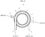
- FIG. 3 is a schematic sectional view of the heat exchanger shown in FIG. 2 .
- the heat exchanger 20 is formed in a double pipe type including a first refrigerant pipe 21 and a second refrigerant pipe 22.
- the first refrigerant pipe 21 defines a first passage 30 thereinside, through which the high pressure refrigerant discharged from the gas cooler 12 flows.
- the first refrigerant pipe 21 and the second refrigerant pipe 22 define a second passage 40 therebetween, through which the low pressure refrigerant discharged from the evaporator 14 flows.
- the first passage 30 and the second passage 40 are arranged so that the refrigerant from the gas cooler 12 and the refrigerant from the evaporator 14 can be heat-exchanged with each other.
- the double pipe type heat exchanger 20 may have a helical structure to increase a heat exchange area.
- an inlet 31 of the first passage 30 is formed at an upper portion of the heat exchanger 20, and an outlet 32 of the first passage 30 is formed at a lower portion of the heat exchanger 20. That is, the high pressure refrigerant discharged from the gas cooler 12 flows into the first passage 30 through the upper inlet 31, and flows out of the heat exchanger 20 through the lower outlet 32.
- an inlet 41 of the second passage 40 is formed at the lower portion of the heat exchanger 20, and an outlet 42 of the second passage 40 is formed at the upper portion of the heat exchanger 20. That is, the low pressure refrigerant discharged from the evaporator 14 flows into the second passage 40 through the lower inlet 41, and flows out of the heat exchanger 20 through the upper outlet 42.
- the heat exchanger 20 of the refrigerant cycle device 1 is configured such that the refrigerant in the first passage 30 flows downward and the refrigerant in the second passage 40 flows upward, when a surplus liquid refrigerant is discharged from the evaporator 14, the second passage 40 of the heat exchanger 20 temporarily stores the liquid refrigerant in its lower portion, just like an accumulator. Accordingly, the inflow of the liquid refrigerant into the compressor 11 can be prevented without installing an additional accumulator, and the more stable refrigerant cycle device 1 can be achieved.
- the low temperature refrigerant flowing through the second passage 40 heat-exchanges with the high temperature refrigerant flowing through the first passage 30, even when the liquid refrigerant is discharged from the evaporator 14, the liquid refrigerant is totally phase-changed into a gas refrigerant, and the gas refrigerant is sucked into the compressor 11.
- the refrigerant in the first passage 30 flows downward, the liquid refrigerant, which may be generated by a temperature condition of outdoor air in a supercritical state, gathers in a downstream side of the first passage 30, i.e., in the expansion valve 13. Therefore, the first passage 30 extending downward serves as a reservoir tank. As a result, the generation of a flash gas can be prevented. Further, since the refrigerant in the first passage 30 is cooled by being heat-exchanged with the refrigerant in the second passage 40, the generation of the flash gas can be further prevented, and thus the deterioration of performance of the expansion valve 13 can be prevented. As a result, the refrigerant cycle device can be operated stably.
- CO2 carbon dioxide
- the refrigerant cycle device 1 In the refrigerant cycle device 1 according to the present invention, carbon dioxide (CO2), which is a natural refrigerant having environment-friendly, non-combustible and nontoxic features, is used as the refrigerant, and the high pressure side is set to a supercritical pressure.
- the refrigerant introduced into the first passage 30 flows from up to down in the first passage 30. At this time, the refrigerant flowing in the first passage 30 is cooled by transferring heat to the refrigerant flowing in the second passage 40.
- the refrigerant is converted into a gas/liquid two-phase refrigerant by a pressure drop in the expansion valve 13, and is introduced into the evaporator 14. While flowing through the evaporator 14, the refrigerant is evaporated, and absorbs heat from air, thereby performing a cooling action.
- the refrigerant discharged from the evaporator is introduced into the inlet 41 of the second passage 40 formed between the first refrigerant pipe 21 and the second refrigerant pipe 22 of the heat exchanger 20, and flows from down to up in the second passage 40 between the first refrigerant pipe 21 and the second refrigerant pipe 22.
- the low temperature refrigerant discharged from the evaporator 14 after being evaporated therein is not a perfect gas phase, but is a gas-liquid mixed phase. If the gas-liquid mixed refrigerant flows in the second passage 40 of the heat exchanger 20 and is heat-exchanged with the refrigerant flowing in the first passage 30, the gas-liquid mixed refrigerant is heated such that superheating of the refrigerant is obtained. Accordingly, the gas-liquid mixed refrigerant is converted into a perfect gas refrigerant. The gas refrigerant is discharged from the heat exchanger 20, and flows to a suction port of the compressor 11 via the refrigerant suction pipe 6.
- the embodiments of the present invention can prevent the liquid refrigerant from being sucked into the compressor without installing an additional accumulator, and can keep the compressor from being broken.
- the heat exchanger 20 including the first passage 30 permitting the inflow of the refrigerant from the gas cooler 12 and the second passage 40 arranged in heat exchangeable relation with the first passage 30 and permitting the inflow of the refrigerant from the evaporator 14, the temperature of the refrigerant flowing into the expansion valve 13 from the gas cooler 12 is lowered, and the entropy difference in the evaporator 14 is increased, thereby enhancing the cooling capacity. Even when the heat radiation of the refrigerant is not achieved sufficiently in the gas cooler 12, the deterioration of performance of the expansion device due to the generation of a flash gas can be prevented by the heat exchanger 20.
- the refrigerant discharged from the evaporator 14 is converted into a perfect gas refrigerant while flowing through the heat exchanger 20 and the liquid refrigerant is temporarily stored in the lower portion of the inlet of the second passage 40, it is unnecessary to install an accumulator to temporarily store the liquid refrigerant. Accordingly, the refrigerant cycle device can be made compact, and manufacturing costs can be saved.
- the refrigerant cycle device according to the embodiment of the present invention as structured above has enhanced reliability and cooling capacity.
- first passage is formed in the first refrigerant pipe and the second passage is formed between the first refrigerant pipe and the second refrigerant pipe
- second passage is formed in the first refrigerant pipe and the first passage is formed between the first refrigerant pipe and the second refrigerant pipe.
- the heat exchanger 20 is formed in a double-pipe structure including the first refrigerant pipe 21 and the second refrigerant pipe 22, however the heat exchanger 20 is not restricted thereto.
- the heat exchanger 20 may be formed in a structure of stacking steel plates having two passages thereinside.
- one passage defined as a first passage and the other passage defined as a second passage should be arranged in a heat exchangeable relation with each other.
- it should be configured such that the refrigerant in the first passage flows from up to down and the refrigerant in the second passage flows from down to up.
- the pressure reducing device in this embodiment is configured as the expansion valve 13, however this is not restricted thereto.
- the pressure reducing device may be configured as an electric type or mechanical type expansion valve.
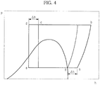
- FIG. 4 is a p-h diagram of the refrigerant cycle of the refrigerant cycle device according to the first embodiment of the present invention.
- the vertical axis refers to a pressure
- the horizontal axis refers to an enthalpy
- the compressor 11 If the compressor 11 is driven, the low pressure gas refrigerant is sucked into the compressor 11, and is compressed into a gas refrigerant of high temperature and high pressure. At this time, the refrigerant is compressed to a supercritical pressure shown by a point "b" in FIG. 4 . The gas refrigerant of high temperature and high pressure is discharged from the compressor 11.
- the refrigerant of high temperature and high pressure is introduced into the gas cooler 12, and heat is radiated.
- the refrigerant is converted into a state shown by point "c" in FIG. 4 , and flows into the inlet 31 of the first passage 30 of the heat exchanger 20.
- the refrigerant of high temperature and high pressure introduced into the heat exchanger 20 is cooled by being heat-exchanged with the refrigerant of low temperature and low pressure introduced into the second passage 40 from the evaporator 14, and is converted into a state shown by a point "d” in FIG. 4 .
- the high pressure refrigerant discharged from the heat exchanger 20 after being cooled in the heat exchanger 20 is introduced into the expansion valve 13. While flowing through the expansion valve 13, the pressure of the refrigerant drops, and the refrigerant is converted into a liquid/gas two-phase refrigerant as shown by point "e" in FIG. 4 . Then, the refrigerant is introduced into the evaporator 14, and absorbs heat from air, thereby performing a cooling action.
- the enthalpy difference in the evaporator 14 is increased, and thus the cooling capacity of the evaporator 14 can be enhanced.
- the refrigerant discharged from the evaporator 14 is converted into a state shown by point "f" in FIG. 4 , and flows into the inlet 41 of the second passage 40 of the heat exchanger 20.
- the low temperature refrigerant heat-exchanged in the evaporator 14 is in the liquid/gas two-phase state.
- Such a two-phase refrigerant is heat-exchanged while flowing through the second passage 40 of the heat exchanger 20, and is phase-changed into a perfect gas refrigerant as shown by point "a” in FIG. 4 , thereby obtaining superheating. Accordingly, since only the gas refrigerant is introduced into the compressor 11, the problem of breakage of the compressor due to the inflow of the liquid refrigerant into the compressor can be prevented.
- the refrigerant heated by the heat exchanger 20 is sucked into the compressor 11, and circulates through the above refrigerant circuit of the refrigerant cycle device.
- both supercooling and superheating are increased.
- the increased supercooling prevents deterioration of performance of the evaporator 14, and the increased superheating prevents the inflow of the liquid refrigerant into the compressor 11, thereby enhancing the reliability of the compressor 11.
- FIG. 5 is a schematic perspective view illustrating a connecting structure of a heat exchanger and an evaporator in a refrigerant cycle device according to a second embodiment of the present invention.
- a heat exchanger of the refrigerant cycle device according to the second embodiment is generally the same as the heat exchanger of the refrigerant cycle device according to the first embodiment.
- the evaporator 14 and the heat exchanger 20 are arranged such that the outlet of the evaporator 14 is provided at a higher position than the inlet 41 of the second passage 40 of the heat exchanger 20.
- the evaporator 14 and the heat exchanger 20 are arranged such that the outlet of the evaporator 14 is positioned at the substantially same height as the outlet 42 of the second passage 40.
- a refrigerant pipe 5' connecting the outlet of the evaporator 14 and the inlet 41 of the second passage 40 is inclined down toward the inlet 41 of the second passage 40.
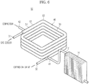
- FIG. 6 is a schematic perspective view illustrating a connecting structure of a heat exchanger and an evaporator in a refrigerant cycle device according to a third embodiment of the present invention
- FIG. 7 is a schematic sectional view of the heat exchanger shown in FIG. 6 .
- a heat exchanger 50 of this embodiment is formed in a double pipe type, and has a substantially rectangular helical structure.
- the heat exchanger 50 is formed with bent portions 53 which are bent with a predetermined interval therebetween.
- double pipe type first and second refrigerant pipes 51 and 52 are contacted with each other at each bent portion 53, thereby forming a contact portion 54.
- first refrigerant pipe 51 and the second refrigerant pipe 52 are contacted with each other at an inner portion of each bent portion 53 which is bent at a substantially right angle.
- the refrigerant cycle device according to the third embodiment has the same constitution and operational effects as the refrigerant cycle device according to the second embodiment.
- a heat exchanger 60 can be configured such that a first refrigerant pipe 61 and a second refrigerant pipe 62 surrounding the first refrigerant pipe 61 are bent in a concave-convex shape. Accordingly, each of bent portions 63 of the concave-convex structure is formed with a contact portion 64, by which the relative movement of the first and second refrigerant pipes 61 and 62 are prevented. As a result, even when vibration is generated at the first and second refrigerant pipes 61 and 62, noise and wear due to the relative movement of the first and second refrigerant pipes 61 and 62 can be prevented.
- a refrigerant cycle device has the same refrigerant circuit as the refrigerant cycle device according to the first embodiment.
- the refrigerant cycle device according to the fourth embodiment has basically the same constitution as the first embodiment, except that a heat exchanger of the fourth embodiment has a substantially rectangular helical structure and an orifice is provided between a first refrigerant pipe and a second refrigerant pipe.
- the same elements as the first embodiment are denoted by the same reference numerals, and the detailed explanation thereof is omitted.
- FIG. 9 is a perspective view illustrating a heat exchanger included in a refrigerant cycle device according to the fourth embodiment of the present invention
- FIG. 10 is a sectional view of portion "A" in FIG. 9 .
- a heat exchanger 20' of the fourth embodiment has a substantially rectangular helical shape.
- the heat exchanger 20' is formed with bending portions which are bent with a predetermined interval therebetween.
- An orifice 80 is provided in the second passage 40 formed between a first refrigerant pipe 71 and a second refrigerant pipe 72, to change a flow rate of the refrigerant.
- the orifice 80 is provided at an inner surface of the second refrigerant pipe 72, and is positioned near the inlet 41 of the second passage 40 to reduce a sectional area of the inlet 41 of the second passage 40. Accordingly, the pressure of the refrigerant flowing through the orifice 80 drops.
- the orifice 80 is provided at the inner surface of the second refrigerant pipe 72, while the refrigerant introduced into the second passage 40 flows through a small sectional area portion 81 formed by the orifice 80, the pressure of the refrigerant drops. Then, while flowing from down to up in the second passage 40 between the first refrigerant pipe 71 and the second refrigerant pipe 72, the refrigerant is heat-exchanged with the refrigerant in the first passage 30.
- the low temperature refrigerant discharged from the evaporator 14 after being evaporated in the evaporator 14 is not a perfect gas refrigerant, but is a gas/liquid mixed refrigerant.
- the gas/liquid mixed refrigerant discharged from the evaporator 14 flows through the second passage 40 of the heat exchanger 20', and is heat-exchanged with the refrigerant flowing through the first passage 30.
- the refrigerant is heated such that the superheating of the refrigerant is obtained, and is converted into a perfect gas refrigerant.
- the gas refrigerant is discharged from the heat exchanger 20', and flows to the suction port of the compressor 11 via the refrigerant suction pipe 6.
- the pressure of the refrigerant passing through the small sectional area portion 81 formed by the orifice 80 is decreased when compared to the related art. Accordingly, a pressure difference between the suction port and the discharge port of the compressor 11 becomes large, and thus the temperature of the refrigerant at the discharge port of the compressor becomes high.
- the refrigerant cycle device when the refrigerant cycle device according to the embodiments of the present invention is applied to a water heater, the temperature of hot water can be increased, thereby enhancing the performance of the water heater.
- FIG. 11 is a p-h diagram of a refrigerant cycle of the refrigerant cycle device according to the fourth embodiment of the present invention.
- a vertical axis refers to a pressure
- a horizontal axis refers to an enthalpy
- the compressor 11 If the compressor 11 is driven, the low pressure gas refrigerant is sucked into the compressor 11, and is compressed into a gas refrigerant of high temperature and high pressure. At this time, the refrigerant is compressed to a supercritical pressure shown by point "b"' in FIG. 11 . The gas refrigerant of high temperature and high pressure is discharged from the compressor 11.
- the refrigerant of high temperature and high pressure is introduced into the gas cooler 12, and heat is radiated.
- the refrigerant is converted into a state shown by point "c"' in FIG. 11 , and flows into the inlet 31 of the first passage 30 of the heat exchanger 20'.
- the refrigerant of high temperature and high pressure introduced into the heat exchanger 20' is cooled by being heat-exchanged with the refrigerant of low temperature and low pressure introduced into the second passage 40 from the evaporator 14, and is converted into a state shown by point "d"' in FIG. 11 .
- the high pressure refrigerant discharged from the heat exchanger 20' after being cooled in the heat exchanger 20' is introduced into the expansion valve 13. While flowing through the expansion valve 13, the pressure of the refrigerant drops, and the refrigerant is converted into a liquid/gas two-phase refrigerant as shown by point "e"' in FIG. 11 . Then, the refrigerant is introduced into the evaporator 14, and absorbs heat from air, thereby performing a cooling action.
- the enthalpy difference in the evaporator 14 is increased, and thus the cooling capacity of the evaporator 14 can be enhanced.
- the refrigerant discharged from the evaporator 14 is converted into a state shown by point "f"' in FIG. 11 , and flows into the inlet 41 of the second passage 40 of the heat exchanger 20'. While passing through the orifice 80 in the inlet 41 of the second passage 40, the pressure of the refrigerant drops.
- the liquid/gas two-phase refrigerant is heat-exchanged while flowing through the second passage 40 of the heat exchanger 20', and is phase-changed into a perfect gas refrigerant as shown by point "a"' in FIG. 11 , thereby obtaining superheating.
- the enthalpy difference ⁇ h is increased more than an enthalpy difference ⁇ h1 in a heat exchanger of the related art. Accordingly, when compared to the related art, heat exchange efficiency is increased, and the heat exchanger with a shorter length can be manufactured, thereby saving manufacturing cost.
- the refrigerant cycle device according to the present invention when applied to a water heater, the temperature of hot water can be increased.
- the refrigerant cycle device can increase heat exchange efficiency without installing an additional accumulator and can be manufactured compactly with low cost, by heat-exchanging the refrigerant in the low pressure side passage and the refrigerant in the high pressure side passage in the heat exchanger while making the refrigerant in the low pressure side passage flow upward and the refrigerant in the high pressure side passage flow downward.
- the outlet of the evaporator is disposed at a higher position than the inlet of the low pressure side passage of the heat exchanger, even when a large amount of surplus liquid refrigerant is discharged from the evaporator, the refrigerant pipe between the outlet of the evaporator and the inlet of the low pressure side passage serves as an accumulator. Accordingly, the inflow of the liquid refrigerant into the compressor can be prevented.
- the double pipe type heat exchanger is formed with the contact portions between the first refrigerant pipe and the second refrigerant pipe, even when vibration is generated, noise and wear due to relative movement of the first and second refrigerant pipes can be prevented.
- the orifice is provided in the inlet of the second passage to decrease the pressure of the refrigerant flowing through the second passage to decrease the pressure of the refrigerant flowing through the second passage, heat exchange efficiency of the heat exchanger can be improved, and the temperature at the discharge port of the compressor can be increased.
Description
- The present invention relates to a refrigerant cycle device, and more particularly to a refrigerant cycle device in which carbon dioxide is used as a refrigerant.
- A conventional refrigerant cycle device includes a refrigerant cycle configured such that a compressor, a gas cooler, a pressure reducing device (e.g., expansion valve) and an evaporator are sequentially pipe-connected to each other in a closed loop.
- Freon (R11, R12, R134a, etc.) has been commonly used as a refrigerant of a refrigerant cycle device. However, because freon discharged in the atmosphere causes problems of global warming, disruption of the ozone layer and the like, there has been research related to the use of a natural refrigerant having little influence on the environment, e.g., oxygen (02), carbon dioxide (CO2), hydrocarbon (HC), ammonia (NH3), or water (H20) as a refrigerant.
- Of the above natural refrigerants, because oxygen and water have low pressure, it is difficult to use these compounds as a refrigerant. Because ammonia and hydrocarbon are combustible, these materials are difficult to handle. Accordingly, there is being developed a device using a transcritical cycle in which carbon dioxide (CO2) is used as a refrigerant and a high pressure side is set to a supercritical pressure.
- A transcritical cycle device is constituted such that an accumulator is mounted to a low pressure side between an outlet of an evaporator and a suction port of a compressor to prevent inflow of a liquid refrigerant into the compressor, and the liquid refrigerant is accumulated in the accumulator, so that only a gas refrigerant is sucked into the compressor.
- However, the conventional refrigerant cycle device has problems such that the charging amount of refrigerant is increased due to the installation of the accumulator and the refrigerant cycle device cannot be made compact.
- To solve the above problems, Korean Patent Laid-Open Publication No.
2006-0041722 - The above-disclosed refrigerant cycle device is a transcritical cycle device in which a compressor, a gas cooler, a pressure reducing device and an evaporator are connected to each other in a closed loop, carbon dioxide is used as a refrigerant, and a high pressure side is set to a supercritical pressure. The disclosed refrigerant cycle device includes an internal heat exchanger to heat-exchange a refrigerant discharged from the gas cooler and a refrigerant discharged from the evaporator. The internal heat exchanger includes a high pressure side passage through which the refrigerant discharged from the gas cooler flows, and a low pressure side passage through which the refrigerant discharged from the evaporator flows. The high pressure side passage and the low pressure side passage are arranged so as to be heat-exchanged with each other. The refrigerant in the high pressure side passage flows from down to up, and the refrigerant in the low pressure side passage flows from up to down.
- By making the refrigerant in the high pressure side passage flow from down to up and the refrigerant in the low pressure side passage flow from up to down, a surplus refrigerant is accumulated in the high pressure side passage, and the amount of surplus refrigerant flowing into the low pressure side passage is reduced. Accordingly, the above-disclosed refrigerant cycle device shows an effect of preventing inflow of a liquid refrigerant into the compressor to a certain extent. However, if a large amount of surplus liquid refrigerant is included in the refrigerant flowing through the evaporator because a temperature around the evaporator is low, the inflow of the liquid refrigerant into the compressor cannot be perfectly prevented by the constitution such that the refrigerant from the evaporator flows from up to down in the low pressure side passage.
- Also because the refrigerant in the high pressure side passage flows from down to up, the liquid refrigerant flowing to the expansion valve is evaporated, and flash gas is generated, which causes deterioration of the performance of the expansion valve.
- Further, because a first refrigerant pipe and a second refrigerant pipe of the internal heat exchanger are spaced apart from each other, when the refrigerant flows through the internal heat exchanger or when vibration by the operation of the compressor is transmitted, the first refrigerant pipe of the internal heat exchanger vibrates to be contacted with the second refrigerant pipe, thereby generating noise. If the first and second refrigerant pipes get worn by the successive contact, operational reliability of the refrigerant cycle device is deteriorated.
- Still further, when a temperature of the refrigerant at the outlet of the evaporator rises, a heat exchange area of the internal heat exchanger should be increased in order to achieve a sufficient heat exchange effect. To fulfill such a requirement, a length of the double pipe type internal heat exchanger should be increased, which results in increase in cost of the internal heat exchanger. There is also a limitation in improving the performance of the refrigeration cycle due to the insufficient heat exchange.
-
JP 2006097911 A -
JP 2002130963 A - Therefore, it is an aspect of the invention to provide a refrigerant cycle device which can prevent inflow of a liquid refrigerant into a compressor and can be manufactured compactly.
- It is another aspect of the invention to provide a refrigerant cycle device using carbon dioxide as a refrigerant, which can reduce noise and improve reliability.
- It is yet another aspect of the invention to provide a refrigerant cycle device which can improve heat exchange efficiency.
- Additional aspects and/or advantages of the invention will be set forth in part in the description which follows and, in part, will be apparent from the description, or may be learned by practice of the invention.
- The foregoing and/or other aspects of the present invention are achieved by providing a refrigerant cycle device comprising: a compressor; a gas cooler; a pressure reducing device; an evaporator, the compressor, the gas cooler, the pressure reducing device and the evaporator being in fluid communication to form a closed loop; and a heat exchanger to heat-exchange a refrigerant discharged from the gas cooler and a refrigerant discharged from the evaporator. The heat exchanger includes a first passage connected to an outlet of the gas cooler and containing the refrigerant discharged from the gas cooler and a second passage connected to an outlet of the evaporator and containing the refrigerant discharged from the evaporator. The refrigerant in the first passage flows downward, and the refrigerant in the second passage flows upward.
- The outlet of the evaporator is disposed at a higher position than an inlet of the second passage.
- The outlet of the evaporator may be connected to the inlet of the second passage by a refrigerant pipe which is inclined downward.
- The heat exchanger may be formed in a double pipe type including a first refrigerant pipe and a second refrigerant pipe surrounding the first refrigerant pipe.
- The first passage may be formed in the first refrigerant pipe, and the second passage may be formed between the first refrigerant pipe and the second refrigerant pipe.
- The heat exchanger may be formed with bending portions with a predetermined interval therebetween, and the bending portions may be formed with contact portions between the first refrigerant pipe and the second refrigerant pipe.
- The heat exchanger may have a substantially rectangular helical shape, and the contact portions may be formed at edge portions of the heat exchanger to prevent relative movement of the first refrigerant pipe and the second refrigerant pipe.
- The refrigerant cycle device may use carbon dioxide as the refrigerant.
- The refrigerant cycle device may further comprise an orifice provided in the second passage to change a flow rate of the refrigerant.
- The orifice may be provided in the inlet of the second passage.
- The first passage may have an outlet and an inlet disposed at a higher position than the outlet of the first passage, and the second passage has an outlet and an inlet disposed at a lower position than the outlet of the second passage.
- The inlet of the first passage may be positioned at the substantially same height as the outlet of the second passage, and the outlet of the first passage may be positioned at the substantially same height as the inlet of the second passage.
- The refrigerant in the first passage may flow upward, and the refrigerant in the second passage may flow downward.
- The heat exchanger may be formed in a double pipe type including a first refrigerant pipe and a second refrigerant pipe surrounding the first refrigerant pipe. The first passage may be formed in the first refrigerant pipe, and the second passage may be formed between the first refrigerant pipe and the second refrigerant pipe.
- The refrigerant cycle device may further comprise an orifice to decrease a pressure of the refrigerant flowing through the second passage.
- The heat exchanger may be formed with at least one contact portion between the first refrigerant pipe and the second refrigerant pipe to prevent relative movement of the first refrigerant pipe and the second refrigerant pipe.
- These and/or other aspects and advantages of the exemplary embodiments of the invention will become apparent and more readily appreciated from the following description of the embodiments, taken in conjunction with the accompanying drawings, of which:
-
FIG. 1 is a refrigerant circuit diagram of a refrigerant cycle device in accordance with the first embodiment of the present invention; -
FIG. 2 is a perspective view illustrating a heat exchanger included in a refrigerant cycle device in accordance with the first embodiment of the present invention; -
FIG. 3 is a schematic sectional view of the heat exchanger shown inFIG. 2 ; -
FIG. 4 is a p-h diagram of a refrigerant cycle of the refrigerant cycle device in accordance with the first embodiment of the present invention; -
FIG. 5 is a schematic perspective view illustrating a connecting structure of a heat exchanger and an evaporator in a refrigerant cycle device in accordance with a second embodiment of the present invention; -
FIG. 6 is a schematic perspective view illustrating a connecting structure of a heat exchanger and an evaporator in a refrigerant cycle device in accordance with a third embodiment of the present invention; -
FIG. 7 is a schematic sectional view of the heat exchanger shown inFIG. 6 ; -
FIG. 8 is a schematic sectional view of a portion of a heat exchanger in accordance with a modified embodiment of the present invention; -
FIG. 9 is a perspective view illustrating a heat exchanger included in a refrigerant cycle device in accordance with a fourth embodiment of the present invention; -
FIG. 10 is a sectional view of portion "A" inFIG. 9 ; and -
FIG. 11 is a p-h diagram of a refrigerant cycle of the refrigerant cycle device in accordance with the fourth embodiment of the present invention. - Reference will now be made in detail to exemplary embodiments of the present invention, examples of which are illustrated in the accompanying drawings, wherein like reference numerals refer to like elements throughout. The embodiments are described below to explain the present invention by referring to the figures.
-
FIG. 1 is a refrigerant circuit diagram of a refrigerant cycle device in accordance with a first embodiment of the present invention. - A refrigerant cycle device according to the embodiment of the present invention is used in an air conditioner, a refrigerator, a display case, or the like.
- As shown in
FIG. 1 , arefrigerant cycle device 1 according to the first embodiment of the present invention is constituted such that acompressor 11, agas cooler 12, an expansion valve 13 (pressure reducing device), and anevaporator 14 are connected to each other in a closed loop. - The
compressor 11 is provided between thegas cooler 12 and theevaporator 14. Thecompressor 11 compresses a gas refrigerant of a low temperature and a low pressure into a gas refrigerant of a high temperature and a high pressure. Various types of compressors, such as a hermetic reciprocating compressor, a rotary compressor, a scroll compressor or the like, can be used. - An inlet of the
gas cooler 12 is connected with arefrigerant discharge pipe 2 extending from thecompressor 11. Apipe 3 connected with an outlet of thegas cooler 12 is connected to aninlet 31 of afirst passage 30 forming a passage for a high pressure refrigerant in aheat exchanger 20. - The
heat exchanger 20 heat-exchanges the high pressure refrigerant discharged from thegas cooler 12 and the low pressure refrigerant discharged from theevaporator 14. Apipe 4 connected with anoutlet 32 of thefirst passage 30 of theheat exchanger 20 is connected to theevaporator 14 via theexpansion valve 13. Apipe 5 connected with an outlet of theevaporator 14 is connected to aninlet 41 of asecond passage 40 forming a passage for a low pressure refrigerant in theheat exchanger 20. - The refrigerant heated while flowing through the
second passage 40 of theheat exchanger 20 is sucked into thecompressor 11 through arefrigerant suction pipe 6, and circulates through the above refrigerant circuit of the refrigerant cycle device. -
FIG. 2 is a perspective view illustrating the heat exchanger included in the refrigerant cycle device according to the first embodiment of the present invention, andFIG. 3 is a schematic sectional view of the heat exchanger shown inFIG. 2 . - As shown in
FIGS. 2 and3 , theheat exchanger 20 is formed in a double pipe type including a firstrefrigerant pipe 21 and a secondrefrigerant pipe 22. The firstrefrigerant pipe 21 defines afirst passage 30 thereinside, through which the high pressure refrigerant discharged from thegas cooler 12 flows. The firstrefrigerant pipe 21 and the secondrefrigerant pipe 22 define asecond passage 40 therebetween, through which the low pressure refrigerant discharged from theevaporator 14 flows. In other words, thefirst passage 30 and thesecond passage 40 are arranged so that the refrigerant from thegas cooler 12 and the refrigerant from theevaporator 14 can be heat-exchanged with each other. - The double pipe
type heat exchanger 20 may have a helical structure to increase a heat exchange area. - In order to make the refrigerant in the
first passage 30 flow from up to down, aninlet 31 of thefirst passage 30 is formed at an upper portion of theheat exchanger 20, and anoutlet 32 of thefirst passage 30 is formed at a lower portion of theheat exchanger 20. That is, the high pressure refrigerant discharged from thegas cooler 12 flows into thefirst passage 30 through theupper inlet 31, and flows out of theheat exchanger 20 through thelower outlet 32. - In order to make the refrigerant in the
second passage 40 flow from down to up, aninlet 41 of thesecond passage 40 is formed at the lower portion of theheat exchanger 20, and anoutlet 42 of thesecond passage 40 is formed at the upper portion of theheat exchanger 20. That is, the low pressure refrigerant discharged from theevaporator 14 flows into thesecond passage 40 through thelower inlet 41, and flows out of theheat exchanger 20 through theupper outlet 42. - Accordingly, since the refrigerant flowing through the
first passage 30 and the refrigerant flowing through thesecond passage 40 flow in opposite directions, heat exchange efficiency of theheat exchanger 20 is enhanced. - Since the
heat exchanger 20 of therefrigerant cycle device 1 according to the first embodiment is configured such that the refrigerant in thefirst passage 30 flows downward and the refrigerant in thesecond passage 40 flows upward, when a surplus liquid refrigerant is discharged from theevaporator 14, thesecond passage 40 of theheat exchanger 20 temporarily stores the liquid refrigerant in its lower portion, just like an accumulator. Accordingly, the inflow of the liquid refrigerant into thecompressor 11 can be prevented without installing an additional accumulator, and the more stablerefrigerant cycle device 1 can be achieved. Also, since the low temperature refrigerant flowing through thesecond passage 40 heat-exchanges with the high temperature refrigerant flowing through thefirst passage 30, even when the liquid refrigerant is discharged from theevaporator 14, the liquid refrigerant is totally phase-changed into a gas refrigerant, and the gas refrigerant is sucked into thecompressor 11. - Because the refrigerant in the
first passage 30 flows downward, the liquid refrigerant, which may be generated by a temperature condition of outdoor air in a supercritical state, gathers in a downstream side of thefirst passage 30, i.e., in theexpansion valve 13. Therefore, thefirst passage 30 extending downward serves as a reservoir tank. As a result, the generation of a flash gas can be prevented. Further, since the refrigerant in thefirst passage 30 is cooled by being heat-exchanged with the refrigerant in thesecond passage 40, the generation of the flash gas can be further prevented, and thus the deterioration of performance of theexpansion valve 13 can be prevented. As a result, the refrigerant cycle device can be operated stably. - In the
refrigerant cycle device 1 according to the present invention, carbon dioxide (CO2), which is a natural refrigerant having environment-friendly, non-combustible and nontoxic features, is used as the refrigerant, and the high pressure side is set to a supercritical pressure. - The refrigerant introduced into the
first passage 30 flows from up to down in thefirst passage 30. At this time, the refrigerant flowing in thefirst passage 30 is cooled by transferring heat to the refrigerant flowing in thesecond passage 40. - The high pressure refrigerant cooled in the
heat exchanger 20 and discharged from thelower outlet 32 flows to theexpansion valve 13. The refrigerant is converted into a gas/liquid two-phase refrigerant by a pressure drop in theexpansion valve 13, and is introduced into theevaporator 14. While flowing through theevaporator 14, the refrigerant is evaporated, and absorbs heat from air, thereby performing a cooling action. - In the above process, since the temperature of the refrigerant flowing into the
expansion valve 13 from thegas cooler 12 can be lowered by theheat exchanger 20, an entropy difference in theevaporator 14 is increased, and thus the cooling capacity of theevaporator 14 can be enhanced. - The refrigerant discharged from the evaporator is introduced into the
inlet 41 of thesecond passage 40 formed between the firstrefrigerant pipe 21 and the secondrefrigerant pipe 22 of theheat exchanger 20, and flows from down to up in thesecond passage 40 between the firstrefrigerant pipe 21 and the secondrefrigerant pipe 22. - The low temperature refrigerant discharged from the
evaporator 14 after being evaporated therein is not a perfect gas phase, but is a gas-liquid mixed phase. If the gas-liquid mixed refrigerant flows in thesecond passage 40 of theheat exchanger 20 and is heat-exchanged with the refrigerant flowing in thefirst passage 30, the gas-liquid mixed refrigerant is heated such that superheating of the refrigerant is obtained. Accordingly, the gas-liquid mixed refrigerant is converted into a perfect gas refrigerant. The gas refrigerant is discharged from theheat exchanger 20, and flows to a suction port of thecompressor 11 via therefrigerant suction pipe 6. - Accordingly, the embodiments of the present invention can prevent the liquid refrigerant from being sucked into the compressor without installing an additional accumulator, and can keep the compressor from being broken.
- As described above, by installing the
heat exchanger 20 including thefirst passage 30 permitting the inflow of the refrigerant from thegas cooler 12 and thesecond passage 40 arranged in heat exchangeable relation with thefirst passage 30 and permitting the inflow of the refrigerant from theevaporator 14, the temperature of the refrigerant flowing into theexpansion valve 13 from thegas cooler 12 is lowered, and the entropy difference in theevaporator 14 is increased, thereby enhancing the cooling capacity. Even when the heat radiation of the refrigerant is not achieved sufficiently in thegas cooler 12, the deterioration of performance of the expansion device due to the generation of a flash gas can be prevented by theheat exchanger 20. - Further, since the refrigerant discharged from the
evaporator 14 is converted into a perfect gas refrigerant while flowing through theheat exchanger 20 and the liquid refrigerant is temporarily stored in the lower portion of the inlet of thesecond passage 40, it is unnecessary to install an accumulator to temporarily store the liquid refrigerant. Accordingly, the refrigerant cycle device can be made compact, and manufacturing costs can be saved. - Still further, since it is possible to accumulate the surplus refrigerant discharged from the
first passage 30 in theexpansion valve 13, the generation of a flash gas can be prevented. - The refrigerant cycle device according to the embodiment of the present invention as structured above has enhanced reliability and cooling capacity.
- Although this embodiment has shown that the first passage is formed in the first refrigerant pipe and the second passage is formed between the first refrigerant pipe and the second refrigerant pipe, it can be modified such that the second passage is formed in the first refrigerant pipe and the first passage is formed between the first refrigerant pipe and the second refrigerant pipe.
- The
heat exchanger 20 is formed in a double-pipe structure including the firstrefrigerant pipe 21 and the secondrefrigerant pipe 22, however theheat exchanger 20 is not restricted thereto. Theheat exchanger 20 may be formed in a structure of stacking steel plates having two passages thereinside. - Also in such a case, one passage defined as a first passage and the other passage defined as a second passage should be arranged in a heat exchangeable relation with each other. In addition, it should be configured such that the refrigerant in the first passage flows from up to down and the refrigerant in the second passage flows from down to up.
- The pressure reducing device in this embodiment is configured as the
expansion valve 13, however this is not restricted thereto. The pressure reducing device may be configured as an electric type or mechanical type expansion valve. - Next, the operation of the
refrigerant cycle device 1 according to the first embodiment of the present invention as structured above will be explained. -
FIG. 4 is a p-h diagram of the refrigerant cycle of the refrigerant cycle device according to the first embodiment of the present invention. - In
FIG. 4 , the vertical axis refers to a pressure, and the horizontal axis refers to an enthalpy. - If the
compressor 11 is driven, the low pressure gas refrigerant is sucked into thecompressor 11, and is compressed into a gas refrigerant of high temperature and high pressure. At this time, the refrigerant is compressed to a supercritical pressure shown by a point "b" inFIG. 4 . The gas refrigerant of high temperature and high pressure is discharged from thecompressor 11. - The refrigerant of high temperature and high pressure is introduced into the
gas cooler 12, and heat is radiated. The refrigerant is converted into a state shown by point "c" inFIG. 4 , and flows into theinlet 31 of thefirst passage 30 of theheat exchanger 20. The refrigerant of high temperature and high pressure introduced into theheat exchanger 20 is cooled by being heat-exchanged with the refrigerant of low temperature and low pressure introduced into thesecond passage 40 from theevaporator 14, and is converted into a state shown by a point "d" inFIG. 4 . - In other words, since the high pressure refrigerant flowing toward the
expansion valve 13 from thegas cooler 12 is heat-exchanged with the low pressure refrigerant in thesecond passage 40 by theheat exchanger 20, the temperature of the high pressure refrigerant can be effectively decreased. Accordingly, an enthalpy of the refrigerant introduced into theexpansion valve 13 drops by a value of Δh, and the refrigerant attains the state shown by point "d" inFIG. 4 . - The high pressure refrigerant discharged from the
heat exchanger 20 after being cooled in theheat exchanger 20 is introduced into theexpansion valve 13. While flowing through theexpansion valve 13, the pressure of the refrigerant drops, and the refrigerant is converted into a liquid/gas two-phase refrigerant as shown by point "e" inFIG. 4 . Then, the refrigerant is introduced into theevaporator 14, and absorbs heat from air, thereby performing a cooling action. - Because the temperature of the refrigerant introduced into the
evaporator 14 drops by the heat exchanging operation of theheat exchanger 20, the enthalpy difference in theevaporator 14 is increased, and thus the cooling capacity of theevaporator 14 can be enhanced. - The refrigerant discharged from the
evaporator 14 is converted into a state shown by point "f" inFIG. 4 , and flows into theinlet 41 of thesecond passage 40 of theheat exchanger 20. At this time, the low temperature refrigerant heat-exchanged in theevaporator 14 is in the liquid/gas two-phase state. Such a two-phase refrigerant is heat-exchanged while flowing through thesecond passage 40 of theheat exchanger 20, and is phase-changed into a perfect gas refrigerant as shown by point "a" inFIG. 4 , thereby obtaining superheating. Accordingly, since only the gas refrigerant is introduced into thecompressor 11, the problem of breakage of the compressor due to the inflow of the liquid refrigerant into the compressor can be prevented. - The refrigerant heated by the
heat exchanger 20 is sucked into thecompressor 11, and circulates through the above refrigerant circuit of the refrigerant cycle device. - As a result, in the
refrigerant cycle device 1 according to the first embodiment of the present invention, both supercooling and superheating are increased. The increased supercooling prevents deterioration of performance of theevaporator 14, and the increased superheating prevents the inflow of the liquid refrigerant into thecompressor 11, thereby enhancing the reliability of thecompressor 11. - Hereinafter, a refrigerant cycle device according to a second embodiment of the present invention will be described.
- The same elements as the first embodiment are denoted by the same reference numerals, and a detailed explanation thereof is omitted.
-
FIG. 5 is a schematic perspective view illustrating a connecting structure of a heat exchanger and an evaporator in a refrigerant cycle device according to a second embodiment of the present invention. - A heat exchanger of the refrigerant cycle device according to the second embodiment is generally the same as the heat exchanger of the refrigerant cycle device according to the first embodiment.
- However, the
evaporator 14 and theheat exchanger 20 are arranged such that the outlet of theevaporator 14 is provided at a higher position than theinlet 41 of thesecond passage 40 of theheat exchanger 20. Specifically, theevaporator 14 and theheat exchanger 20 are arranged such that the outlet of theevaporator 14 is positioned at the substantially same height as theoutlet 42 of thesecond passage 40. - Therefore, a refrigerant pipe 5' connecting the outlet of the
evaporator 14 and theinlet 41 of thesecond passage 40 is inclined down toward theinlet 41 of thesecond passage 40. - By virtue of the above constitution, even when a large amount of surplus liquid refrigerant is discharged from the
evaporator 14 because a temperature around theevaporator 14 is specifically low, the lower portion of thesecond passage 40 and the refrigerant pipe 5' between the outlet of theevaporator 14 and theinlet 41 of thesecond passage 40 serve as an accumulator. As a result, the effect of preventing breakage of the compressor can be more enhanced. - Hereinafter, a refrigerant cycle device according to a third embodiment of the present invention will be described.
- The same elements as the second embodiment are denoted by the same reference numerals, and the detailed explanation thereof is omitted.
-
FIG. 6 is a schematic perspective view illustrating a connecting structure of a heat exchanger and an evaporator in a refrigerant cycle device according to a third embodiment of the present invention, andFIG. 7 is a schematic sectional view of the heat exchanger shown inFIG. 6 . - As shown in
FIGS. 6 and7 , aheat exchanger 50 of this embodiment is formed in a double pipe type, and has a substantially rectangular helical structure. In order for theheat exchanger 50 to have a rectangular helical structure, theheat exchanger 50 is formed withbent portions 53 which are bent with a predetermined interval therebetween. - By the above configuration of bending the
heat exchanger 50, double pipe type first and secondrefrigerant pipes bent portion 53, thereby forming acontact portion 54. In other words, the firstrefrigerant pipe 51 and the secondrefrigerant pipe 52 are contacted with each other at an inner portion of eachbent portion 53 which is bent at a substantially right angle. - Accordingly, even when vibration is generated at the first and second
refrigerant pipes compressor 11, since the first and secondrefrigerant pipes contact portion 54, noise and wear due to relative movement of the first and secondrefrigerant pipes - Except for the above structural features, the refrigerant cycle device according to the third embodiment has the same constitution and operational effects as the refrigerant cycle device according to the second embodiment.
- Also, as shown in
FIG. 8 , aheat exchanger 60 can be configured such that a firstrefrigerant pipe 61 and a secondrefrigerant pipe 62 surrounding the firstrefrigerant pipe 61 are bent in a concave-convex shape. Accordingly, each ofbent portions 63 of the concave-convex structure is formed with acontact portion 64, by which the relative movement of the first and secondrefrigerant pipes refrigerant pipes refrigerant pipes - Hereinafter, a refrigerant cycle device according to a fourth embodiment of the present invention will be described.
- A refrigerant cycle device according to the fourth embodiment has the same refrigerant circuit as the refrigerant cycle device according to the first embodiment. The refrigerant cycle device according to the fourth embodiment has basically the same constitution as the first embodiment, except that a heat exchanger of the fourth embodiment has a substantially rectangular helical structure and an orifice is provided between a first refrigerant pipe and a second refrigerant pipe. The same elements as the first embodiment are denoted by the same reference numerals, and the detailed explanation thereof is omitted.
-
FIG. 9 is a perspective view illustrating a heat exchanger included in a refrigerant cycle device according to the fourth embodiment of the present invention, andFIG. 10 is a sectional view of portion "A" inFIG. 9 . - A heat exchanger 20' of the fourth embodiment has a substantially rectangular helical shape. In order for the heat exchanger 20' to have a rectangular helical structure, the heat exchanger 20' is formed with bending portions which are bent with a predetermined interval therebetween.
- An
orifice 80 is provided in thesecond passage 40 formed between a firstrefrigerant pipe 71 and a secondrefrigerant pipe 72, to change a flow rate of the refrigerant. - The
orifice 80 is provided at an inner surface of the secondrefrigerant pipe 72, and is positioned near theinlet 41 of thesecond passage 40 to reduce a sectional area of theinlet 41 of thesecond passage 40. Accordingly, the pressure of the refrigerant flowing through theorifice 80 drops. - Since the
orifice 80 is provided at the inner surface of the secondrefrigerant pipe 72, while the refrigerant introduced into thesecond passage 40 flows through a smallsectional area portion 81 formed by theorifice 80, the pressure of the refrigerant drops. Then, while flowing from down to up in thesecond passage 40 between the firstrefrigerant pipe 71 and the secondrefrigerant pipe 72, the refrigerant is heat-exchanged with the refrigerant in thefirst passage 30. - At this time, the low temperature refrigerant discharged from the
evaporator 14 after being evaporated in theevaporator 14 is not a perfect gas refrigerant, but is a gas/liquid mixed refrigerant. The gas/liquid mixed refrigerant discharged from theevaporator 14 flows through thesecond passage 40 of the heat exchanger 20', and is heat-exchanged with the refrigerant flowing through thefirst passage 30. The refrigerant is heated such that the superheating of the refrigerant is obtained, and is converted into a perfect gas refrigerant. The gas refrigerant is discharged from the heat exchanger 20', and flows to the suction port of thecompressor 11 via therefrigerant suction pipe 6. - The pressure of the refrigerant passing through the small
sectional area portion 81 formed by theorifice 80 is decreased when compared to the related art. Accordingly, a pressure difference between the suction port and the discharge port of thecompressor 11 becomes large, and thus the temperature of the refrigerant at the discharge port of the compressor becomes high. - By virtue of the above effect, when the refrigerant cycle device according to the embodiments of the present invention is applied to a water heater, the temperature of hot water can be increased, thereby enhancing the performance of the water heater.
-
FIG. 11 is a p-h diagram of a refrigerant cycle of the refrigerant cycle device according to the fourth embodiment of the present invention. - In
FIG. 11 , a vertical axis refers to a pressure, and a horizontal axis refers to an enthalpy. - Next, the operation of the refrigerant cycle device according to the embodiments of the present invention as structured above will be explained with reference to
FIGS. 1 and9 to 11 . - If the
compressor 11 is driven, the low pressure gas refrigerant is sucked into thecompressor 11, and is compressed into a gas refrigerant of high temperature and high pressure. At this time, the refrigerant is compressed to a supercritical pressure shown by point "b"' inFIG. 11 . The gas refrigerant of high temperature and high pressure is discharged from thecompressor 11. - The refrigerant of high temperature and high pressure is introduced into the
gas cooler 12, and heat is radiated. The refrigerant is converted into a state shown by point "c"' inFIG. 11 , and flows into theinlet 31 of thefirst passage 30 of the heat exchanger 20'. The refrigerant of high temperature and high pressure introduced into the heat exchanger 20' is cooled by being heat-exchanged with the refrigerant of low temperature and low pressure introduced into thesecond passage 40 from theevaporator 14, and is converted into a state shown by point "d"' inFIG. 11 . - In other words, since the high pressure refrigerant flowing toward the
expansion valve 13 from thegas cooler 12 is heat-exchanged with the low pressure refrigerant in thesecond passage 40 by the heat exchanger 20', the temperature of the high pressure refrigerant can be effectively decreased. Accordingly, an enthalpy of the refrigerant introduced into theexpansion valve 13 drops by a value of Δh, and the refrigerant becomes the state shown by point "d"' inFIG. 11 . - The high pressure refrigerant discharged from the heat exchanger 20' after being cooled in the heat exchanger 20' is introduced into the
expansion valve 13. While flowing through theexpansion valve 13, the pressure of the refrigerant drops, and the refrigerant is converted into a liquid/gas two-phase refrigerant as shown by point "e"' inFIG. 11 . Then, the refrigerant is introduced into theevaporator 14, and absorbs heat from air, thereby performing a cooling action. - Because the temperature of the refrigerant introduced into the
evaporator 14 drops by the heat exchanging operation of the heat exchanger 20', the enthalpy difference in theevaporator 14 is increased, and thus the cooling capacity of theevaporator 14 can be enhanced. - The refrigerant discharged from the
evaporator 14 is converted into a state shown by point "f"' inFIG. 11 , and flows into theinlet 41 of thesecond passage 40 of the heat exchanger 20'. While passing through theorifice 80 in theinlet 41 of thesecond passage 40, the pressure of the refrigerant drops. The liquid/gas two-phase refrigerant is heat-exchanged while flowing through thesecond passage 40 of the heat exchanger 20', and is phase-changed into a perfect gas refrigerant as shown by point "a"' inFIG. 11 , thereby obtaining superheating. Since the refrigerant in thesecond passage 40, whose pressure drops while flowing through theorifice 80, is heat-exchanged with the refrigerant in thefirst passage 30, the enthalpy difference Δh is increased more than an enthalpy difference Δh1 in a heat exchanger of the related art. Accordingly, when compared to the related art, heat exchange efficiency is increased, and the heat exchanger with a shorter length can be manufactured, thereby saving manufacturing cost. - Also, since the pressure of the suction port of the
compressor 11 is decreased by the refrigerant whose pressure is decreased while flowing through theorifice 80, a pressure difference between the suction port and the discharge port of thecompressor 11 is increased when compared to the related art. Accordingly, the temperature of the refrigerant at the discharge port of thecompressor 11 becomes high. - As a result, when the refrigerant cycle device according to the present invention is applied to a water heater, the temperature of hot water can be increased.
- As apparent from the above description, the refrigerant cycle device according to the embodiments of the present invention can increase heat exchange efficiency without installing an additional accumulator and can be manufactured compactly with low cost, by heat-exchanging the refrigerant in the low pressure side passage and the refrigerant in the high pressure side passage in the heat exchanger while making the refrigerant in the low pressure side passage flow upward and the refrigerant in the high pressure side passage flow downward.
- Further, since the outlet of the evaporator is disposed at a higher position than the inlet of the low pressure side passage of the heat exchanger, even when a large amount of surplus liquid refrigerant is discharged from the evaporator, the refrigerant pipe between the outlet of the evaporator and the inlet of the low pressure side passage serves as an accumulator. Accordingly, the inflow of the liquid refrigerant into the compressor can be prevented.
- Further, since the double pipe type heat exchanger is formed with the contact portions between the first refrigerant pipe and the second refrigerant pipe, even when vibration is generated, noise and wear due to relative movement of the first and second refrigerant pipes can be prevented.
- Still further, since the orifice is provided in the inlet of the second passage to decrease the pressure of the refrigerant flowing through the second passage, heat exchange efficiency of the heat exchanger can be improved, and the temperature at the discharge port of the compressor can be increased.
- Although embodiments of the present invention have been shown and described, it would be appreciated by those skilled in the art that changes may be made in these embodiments without departing from the principles of the invention, the scope of which is defined in the claims and their equivalents.
Claims (13)
- A refrigerant cycle device comprising:a compressor (11);a gas cooler (12);a pressure reducing device (13);an evaporator (14), the compressor, the gas cooler, the pressure reducing device and the evaporator being in fluid communication to form a closed loop; anda heat exchanger (20, 20', 50, 60) to heat-exchange a refrigerant discharged from the gas cooler (12) and a refrigerant discharged from the evaporator (14), the heat exchanger including a first passage (30) connected to an outlet of the gas cooler and containing the refrigerant discharged from the gas cooler and a second passage (40) connected to an outlet of the evaporator and containing the refrigerant discharged from the evaporator,wherein the refrigerant in the first passage (30) flows downward, and the refrigerant in the second passage (40) flows upward, characterized in thatthe outlet of the evaporator (14) is disposed at a higher position than an inlet (41) of the second passage (40).
- The refrigerant cycle device according to claim 1, further comprising a refrigerant pipe (5,5'), wherein the outlet of the evaporator (14) is connected to an inlet (41) of the second passage (40) by the refrigerant pipe,
and wherein the refrigerant pipe (5,5') is inclined downward. - The refrigerant cycle device according to claim 1, wherein the heat exchanger (20, 20', 50, 60) is a double pipe type heat exchanger including a first refrigerant pipe (21, 51, 61, 71) and a second refrigerant pipe (22, 52, 62, 72) surrounding the first refrigerant pipe.
- The refrigerant cycle device according to claim 3, wherein the first passage (30) is formed in the first refrigerant pipe, and the second passage (40) is formed between the first refrigerant pipe and the second refrigerant pipe.
- The refrigerant cycle device according to claim 3, wherein the heat exchanger (20', 50, 60) comprises bent portions (53, 63) with a predetermined interval therebetween,
and the bent portions are each formed with contact portions (54, 64), at least one contact portion being in contact with the first refrigerant. - The refrigerant cycle device according to claim 5, wherein the heat exchanger (20', 50) has a substantially rectangular helical shape, and the contact portions (54) are formed at edge portions of the heat exchanger to prevent relative movement of the first refrigerant pipe and the second refrigerant pipe.
- The refrigerant cycle device according to claim 1, wherein the refrigerant is carbon dioxide.
- The refrigerant cycle device according to claim 1, further comprising:an orifice (80, 81) provided in the second passage (40) to change a flow rate of the refrigerant.
- The refrigerant cycle device according to claim 8, wherein the orifice (80, 81) is provided in an inlet (41) of the second passage (40).
- The refrigerant cycle device according to claim 1,
wherein the first passage (30) has an outlet (32) and an inlet (31) disposed at a higher position than the outlet (32) of the first passage, and the second passage (40) has an outlet (42) and an inlet (41) disposed at a lower position than the outlet (42) of the second passage. - The refrigerant cycle device according to claim 10, wherein the inlet (31) of the first passage (30) is positioned at a substantially same height as the outlet (42) of the second passage (40), and the outlet (32) of the first passage (30) is positioned at a substantially same height as the inlet (41) of the second passage.
- The refrigerant cycle device according to claim 10, wherein the heat exchanger (20, 20', 50, 60) is a double pipe type heat exchanger including a first refrigerant pipe (21, 51, 61) and a second refrigerant pipe (22, 52, 62) surrounding the first refrigerant pipe, the first passage (30) is formed in the first refrigerant pipe, and the second passage (40) is formed between the first refrigerant pipe and the second refrigerant pipe.
- The refrigerant cycle device according to claim 10, further comprising:an orifice (80, 81) defined in the second passage (40) to decrease a pressure of the refrigerant flowing through the second passage.
Applications Claiming Priority (2)
| Application Number | Priority Date | Filing Date | Title |
|---|---|---|---|
| KR1020070034442A KR100836824B1 (en) | 2007-04-06 | 2007-04-06 | Refrigerant cycle device |
| KR1020070034443A KR100839078B1 (en) | 2007-04-06 | 2007-04-06 | Refrigerant cycle device |
Publications (3)
| Publication Number | Publication Date |
|---|---|
| EP1978317A2 EP1978317A2 (en) | 2008-10-08 |
| EP1978317A3 EP1978317A3 (en) | 2010-04-21 |
| EP1978317B1 true EP1978317B1 (en) | 2017-09-06 |
Family
ID=39591467
Family Applications (1)
| Application Number | Title | Priority Date | Filing Date |
|---|---|---|---|
| EP08152370.6A Expired - Fee Related EP1978317B1 (en) | 2007-04-06 | 2008-03-06 | Refrigerant cycle device |
Country Status (3)
| Country | Link |
|---|---|
| US (1) | US8099977B2 (en) |
| EP (1) | EP1978317B1 (en) |
| JP (1) | JP2008256350A (en) |
Families Citing this family (9)
| Publication number | Priority date | Publication date | Assignee | Title |
|---|---|---|---|---|
| FR2928997B1 (en) * | 2008-03-20 | 2014-06-20 | Valeo Systemes Thermiques | HEAT EXCHANGER AND INTEGRATED AIR CONDITIONING ASSEMBLY COMPRISING SUCH AN EXCHANGER. |
| EP2275757B1 (en) * | 2008-03-31 | 2018-02-28 | Mitsubishi Electric Corporation | Air-conditioning and hot water complex system |
| IT1391184B1 (en) * | 2008-07-23 | 2011-11-18 | Dayco Fluid Tech S P A | ADDUCTION GROUP FOR A CONDITIONED AIR CIRCUIT WITH A HEAT EXCHANGER |
| KR101280381B1 (en) * | 2009-11-18 | 2013-07-01 | 엘지전자 주식회사 | Heat pump |
| JP2011112351A (en) * | 2009-11-30 | 2011-06-09 | Sanyo Electric Co Ltd | Refrigerating device |
| NO335450B1 (en) * | 2011-06-30 | 2014-12-15 | Aker Subsea As | Seabed compression device |
| CN108224830A (en) * | 2017-12-27 | 2018-06-29 | 安徽环球星新能源科技有限公司 | A kind of CO 2 trans-critical heat pump gas cooler |
| EP3767201B1 (en) * | 2018-03-13 | 2023-08-16 | E . T . L Corporation | Heating and cooling system |
| EP3964372A1 (en) * | 2020-09-03 | 2022-03-09 | TI Automotive Technology Center GmbH | Tube assembly for transporting temperature control media |
Family Cites Families (16)
| Publication number | Priority date | Publication date | Assignee | Title |
|---|---|---|---|---|
| JPH11183062A (en) | 1997-12-18 | 1999-07-06 | Maruyasu Ind Co Ltd | Double piped heat exchanger |
| DE19944951B4 (en) * | 1999-09-20 | 2010-06-10 | Behr Gmbh & Co. Kg | Air conditioning with internal heat exchanger |
| JP2002130849A (en) * | 2000-10-30 | 2002-05-09 | Calsonic Kansei Corp | Cooling cycle and its control method |
| JP2002130963A (en) | 2000-10-30 | 2002-05-09 | Mitsubishi Heavy Ind Ltd | Intercooler and air conditioning device for co2 refrigerant vehicle |
| JP2002156162A (en) * | 2000-11-16 | 2002-05-31 | Mitsubishi Heavy Ind Ltd | Intercooler and air conditioner for vehicle using co2 refrigerant |
| JP2003106784A (en) * | 2001-09-28 | 2003-04-09 | Calsonic Kansei Corp | Heat exchanger |
| JP2004142701A (en) * | 2002-10-28 | 2004-05-20 | Zexel Valeo Climate Control Corp | Refrigeration cycle |
| JP4196774B2 (en) | 2003-07-29 | 2008-12-17 | 株式会社デンソー | Internal heat exchanger |
| US7131294B2 (en) * | 2004-01-13 | 2006-11-07 | Tecumseh Products Company | Method and apparatus for control of carbon dioxide gas cooler pressure by use of a capillary tube |
| TWI324242B (en) | 2004-02-12 | 2010-05-01 | Sanyo Electric Co | Refrigerant cycle apparatus |
| JP2005337700A (en) * | 2004-04-28 | 2005-12-08 | Fuji Electric Retail Systems Co Ltd | Refrigerant cooling circuit |
| JP2005345074A (en) | 2004-06-07 | 2005-12-15 | Mitsubishi Heavy Ind Ltd | Multi-wound type double pipe heat exchanger and air conditioner |
| JP2006097911A (en) | 2004-09-28 | 2006-04-13 | Calsonic Kansei Corp | Heat exchanger |
| CN1862151A (en) | 2005-05-12 | 2006-11-15 | 乐金电子(天津)电器有限公司 | Air conditioner for regenerative cooling circulation system |
| JP2006336943A (en) | 2005-06-02 | 2006-12-14 | Matsushita Electric Ind Co Ltd | Refrigeration system, and cold insulation box |
| US20080202156A1 (en) * | 2007-02-26 | 2008-08-28 | Youngkee Baek | Air-conditioning system for vehicles |
-
2008
- 2008-03-06 EP EP08152370.6A patent/EP1978317B1/en not_active Expired - Fee Related
- 2008-03-10 US US12/073,812 patent/US8099977B2/en not_active Expired - Fee Related
- 2008-03-19 JP JP2008072449A patent/JP2008256350A/en active Pending
Non-Patent Citations (1)
| Title |
|---|
| None * |
Also Published As
| Publication number | Publication date |
|---|---|
| US20080245098A1 (en) | 2008-10-09 |
| JP2008256350A (en) | 2008-10-23 |
| EP1978317A2 (en) | 2008-10-08 |
| EP1978317A3 (en) | 2010-04-21 |
| US8099977B2 (en) | 2012-01-24 |
Similar Documents
| Publication | Publication Date | Title |
|---|---|---|
| EP1978317B1 (en) | Refrigerant cycle device | |
| US7225635B2 (en) | Refrigerant cycle apparatus | |
| JP3948475B2 (en) | Air conditioner | |
| US7464563B2 (en) | Air-conditioner having a dual-refrigerant cycle | |
| EP1804011A2 (en) | Refrigerator | |
| CN104024782B (en) | Heat exchanger and refrigerating plant | |
| JP4363997B2 (en) | Refrigeration equipment | |
| CN108361884A (en) | Air-conditioning system | |
| KR100836824B1 (en) | Refrigerant cycle device | |
| JP5202726B2 (en) | Load-side relay unit and combined air conditioning and hot water supply system | |
| JP3877207B2 (en) | Hot water supply system for CO2 refrigeration cycle | |
| CN102713156B (en) | Volume type expander and refrigeration cycle device using the volume type expander | |
| JP6643627B2 (en) | Heat generation unit | |
| CN115014003B (en) | Regenerator, refrigerating system and refrigerating equipment | |
| CN105264304B (en) | Air conditioner | |
| KR100883600B1 (en) | Air conditioner | |
| JP5163161B2 (en) | Auxiliary heating unit and air conditioner | |
| KR100839078B1 (en) | Refrigerant cycle device | |
| KR101418155B1 (en) | An air conditioner | |
| JP7008178B2 (en) | Refrigeration cycle device and hot water generator equipped with it | |
| JPWO2013027237A1 (en) | Two-stage compressor and heat pump device | |
| JPH10220911A (en) | Air conditioner | |
| CN216205569U (en) | Capillary tube component and heat exchange device with same | |
| JP4983878B2 (en) | Heat exchanger, refrigerator equipped with this heat exchanger, and air conditioner | |
| KR101425041B1 (en) | Outdoor heat exchanger |
Legal Events
| Date | Code | Title | Description |
|---|---|---|---|
| PUAI | Public reference made under article 153(3) epc to a published international application that has entered the european phase |
Free format text: ORIGINAL CODE: 0009012 |
|
| AK | Designated contracting states |
Kind code of ref document: A2 Designated state(s): AT BE BG CH CY CZ DE DK EE ES FI FR GB GR HR HU IE IS IT LI LT LU LV MC MT NL NO PL PT RO SE SI SK TR |
|
| AX | Request for extension of the european patent |
Extension state: AL BA MK RS |
|
| PUAL | Search report despatched |
Free format text: ORIGINAL CODE: 0009013 |
|
| AK | Designated contracting states |
Kind code of ref document: A3 Designated state(s): AT BE BG CH CY CZ DE DK EE ES FI FR GB GR HR HU IE IS IT LI LT LU LV MC MT NL NO PL PT RO SE SI SK TR |
|
| AX | Request for extension of the european patent |
Extension state: AL BA MK RS |
|
| 17P | Request for examination filed |
Effective date: 20100917 |
|
| 17Q | First examination report despatched |
Effective date: 20101020 |
|
| AKX | Designation fees paid |
Designated state(s): DE FR IT |
|
| RAP1 | Party data changed (applicant data changed or rights of an application transferred) |
Owner name: SAMSUNG ELECTRONICS CO., LTD. |
|
| GRAP | Despatch of communication of intention to grant a patent |
Free format text: ORIGINAL CODE: EPIDOSNIGR1 |
|
| INTG | Intention to grant announced |
Effective date: 20170316 |
|
| GRAS | Grant fee paid |
Free format text: ORIGINAL CODE: EPIDOSNIGR3 |
|
| GRAA | (expected) grant |
Free format text: ORIGINAL CODE: 0009210 |
|
| AK | Designated contracting states |
Kind code of ref document: B1 Designated state(s): DE FR IT |
|
| REG | Reference to a national code |
Ref country code: DE Ref legal event code: R096 Ref document number: 602008051981 Country of ref document: DE |
|
| REG | Reference to a national code |
Ref country code: DE Ref legal event code: R097 Ref document number: 602008051981 Country of ref document: DE |
|
| PLBE | No opposition filed within time limit |
Free format text: ORIGINAL CODE: 0009261 |
|
| STAA | Information on the status of an ep patent application or granted ep patent |
Free format text: STATUS: NO OPPOSITION FILED WITHIN TIME LIMIT |
|
| 26N | No opposition filed |
Effective date: 20180607 |
|
| PG25 | Lapsed in a contracting state [announced via postgrant information from national office to epo] |
Ref country code: FR Free format text: LAPSE BECAUSE OF NON-PAYMENT OF DUE FEES Effective date: 20180331 |
|
| PGFP | Annual fee paid to national office [announced via postgrant information from national office to epo] |
Ref country code: DE Payment date: 20190322 Year of fee payment: 12 Ref country code: IT Payment date: 20190312 Year of fee payment: 12 |
|
| REG | Reference to a national code |
Ref country code: DE Ref legal event code: R119 Ref document number: 602008051981 Country of ref document: DE |
|
| PG25 | Lapsed in a contracting state [announced via postgrant information from national office to epo] |
Ref country code: DE Free format text: LAPSE BECAUSE OF NON-PAYMENT OF DUE FEES Effective date: 20201001 |
|
| PG25 | Lapsed in a contracting state [announced via postgrant information from national office to epo] |
Ref country code: IT Free format text: LAPSE BECAUSE OF NON-PAYMENT OF DUE FEES Effective date: 20200306 |