CN100382910C - Method of producing individualized vehicle parts, particularly individualized vehicle body skin parts consisting of series-produced vehicle body skin parts, as well as vehicle body skin parts manufact - Google Patents
Method of producing individualized vehicle parts, particularly individualized vehicle body skin parts consisting of series-produced vehicle body skin parts, as well as vehicle body skin parts manufact Download PDFInfo
- Publication number
- CN100382910C CN100382910C CNB2004800144869A CN200480014486A CN100382910C CN 100382910 C CN100382910 C CN 100382910C CN B2004800144869 A CNB2004800144869 A CN B2004800144869A CN 200480014486 A CN200480014486 A CN 200480014486A CN 100382910 C CN100382910 C CN 100382910C
- Authority
- CN
- China
- Prior art keywords
- standard component
- shaping jig
- mandrel shape
- finishing
- outer casing
- Prior art date
- Legal status (The legal status is an assumption and is not a legal conclusion. Google has not performed a legal analysis and makes no representation as to the accuracy of the status listed.)
- Expired - Lifetime
Links
- 238000000034 method Methods 0.000 title claims description 85
- 238000004519 manufacturing process Methods 0.000 claims abstract description 15
- 238000007493 shaping process Methods 0.000 claims description 48
- 238000007730 finishing process Methods 0.000 claims description 19
- 239000000463 material Substances 0.000 claims description 19
- 230000008569 process Effects 0.000 claims description 19
- 238000012545 processing Methods 0.000 claims description 10
- 230000008859 change Effects 0.000 claims description 8
- 230000008093 supporting effect Effects 0.000 claims description 8
- 239000004033 plastic Substances 0.000 claims description 7
- 229920003023 plastic Polymers 0.000 claims description 7
- 239000002994 raw material Substances 0.000 claims description 5
- 238000005452 bending Methods 0.000 claims description 2
- 238000005096 rolling process Methods 0.000 claims description 2
- 229920001169 thermoplastic Polymers 0.000 claims description 2
- 239000004416 thermosoftening plastic Substances 0.000 claims description 2
- 238000000748 compression moulding Methods 0.000 claims 1
- 230000000694 effects Effects 0.000 claims 1
- 238000004049 embossing Methods 0.000 abstract 1
- 238000000465 moulding Methods 0.000 description 33
- 238000013461 design Methods 0.000 description 7
- 230000001050 lubricating effect Effects 0.000 description 6
- 239000011248 coating agent Substances 0.000 description 4
- 238000000576 coating method Methods 0.000 description 4
- 238000005516 engineering process Methods 0.000 description 4
- 238000003825 pressing Methods 0.000 description 4
- 238000007634 remodeling Methods 0.000 description 4
- 229910000831 Steel Inorganic materials 0.000 description 3
- 230000008901 benefit Effects 0.000 description 3
- 239000012530 fluid Substances 0.000 description 3
- 230000012447 hatching Effects 0.000 description 3
- 238000010438 heat treatment Methods 0.000 description 3
- 238000012805 post-processing Methods 0.000 description 3
- 239000010959 steel Substances 0.000 description 3
- 208000034189 Sclerosis Diseases 0.000 description 2
- 239000013078 crystal Substances 0.000 description 2
- 238000003698 laser cutting Methods 0.000 description 2
- 238000003754 machining Methods 0.000 description 2
- 238000005192 partition Methods 0.000 description 2
- 238000005498 polishing Methods 0.000 description 2
- 239000000047 product Substances 0.000 description 2
- 239000013589 supplement Substances 0.000 description 2
- 238000012360 testing method Methods 0.000 description 2
- 230000003044 adaptive effect Effects 0.000 description 1
- 238000010923 batch production Methods 0.000 description 1
- 244000309464 bull Species 0.000 description 1
- 239000002537 cosmetic Substances 0.000 description 1
- 238000005520 cutting process Methods 0.000 description 1
- 238000010586 diagram Methods 0.000 description 1
- 230000004069 differentiation Effects 0.000 description 1
- 230000002045 lasting effect Effects 0.000 description 1
- 239000010687 lubricating oil Substances 0.000 description 1
- 239000003973 paint Substances 0.000 description 1
- 238000013138 pruning Methods 0.000 description 1
- 239000004576 sand Substances 0.000 description 1
- 239000011265 semifinished product Substances 0.000 description 1
- 230000035807 sensation Effects 0.000 description 1
- 238000005480 shot peening Methods 0.000 description 1
- 239000007921 spray Substances 0.000 description 1
- 230000003746 surface roughness Effects 0.000 description 1
- 230000007704 transition Effects 0.000 description 1
- LENZDBCJOHFCAS-UHFFFAOYSA-N tris Chemical compound OCC(N)(CO)CO LENZDBCJOHFCAS-UHFFFAOYSA-N 0.000 description 1
Images


Classifications
-
- B—PERFORMING OPERATIONS; TRANSPORTING
- B21—MECHANICAL METAL-WORKING WITHOUT ESSENTIALLY REMOVING MATERIAL; PUNCHING METAL
- B21D—WORKING OR PROCESSING OF SHEET METAL OR METAL TUBES, RODS OR PROFILES WITHOUT ESSENTIALLY REMOVING MATERIAL; PUNCHING METAL
- B21D22/00—Shaping without cutting, by stamping, spinning, or deep-drawing
- B21D22/14—Spinning
- B21D22/18—Spinning using tools guided to produce the required profile
-
- B—PERFORMING OPERATIONS; TRANSPORTING
- B21—MECHANICAL METAL-WORKING WITHOUT ESSENTIALLY REMOVING MATERIAL; PUNCHING METAL
- B21D—WORKING OR PROCESSING OF SHEET METAL OR METAL TUBES, RODS OR PROFILES WITHOUT ESSENTIALLY REMOVING MATERIAL; PUNCHING METAL
- B21D22/00—Shaping without cutting, by stamping, spinning, or deep-drawing
- B21D22/20—Deep-drawing
- B21D22/26—Deep-drawing for making peculiarly, e.g. irregularly, shaped articles
-
- B—PERFORMING OPERATIONS; TRANSPORTING
- B21—MECHANICAL METAL-WORKING WITHOUT ESSENTIALLY REMOVING MATERIAL; PUNCHING METAL
- B21D—WORKING OR PROCESSING OF SHEET METAL OR METAL TUBES, RODS OR PROFILES WITHOUT ESSENTIALLY REMOVING MATERIAL; PUNCHING METAL
- B21D53/00—Making other particular articles
- B21D53/88—Making other particular articles other parts for vehicles, e.g. cowlings, mudguards
Abstract
Disclosed is a method for producing vehicle parts, particularly shell parts for vehicles, according to which a three-dimensionally preformed semi-finished or finished standard part, especially a standard shell part, is produced for a serially manufactured vehicle type. An individualized part is then produced from the preformed standard part (1) by subsequently embossing a three-dimensional contour (2) into the standard part by means of a spike-type reshaping tool (14) which is pressed against the standard part from one side while being displaced relative to said standard part.
Description
Technical field
The present invention relates to method and a kind of outer casing member of according to said method making that a kind of manufacturing is used for the outer casing member of automobile.
Background technology
Body of a motor car spare as hood, roof, beater or beat-up, gusset spare, luggage-boot lid or the like, is made by flat material plate by the pull and stretch mode usually.The mould of pull and stretch forcing press is very expensive as everyone knows, and therefore can only under the situation of big relatively number of packages, use be only profitable.The sheet material geometry that this external its complexity aspect can be made with traditional pull and stretch forcing press is limited.Yet the Automobile Design personnel require more and more wide design space, and these can not be met with traditional cupping tool always.Modern Automobile Design is honor with the transition between member section convex and spill and with (stark akzenturieren) characteristic curve of giving prominence to strongly or the seamed edge that has the very little radius of curvature of part for example.May run into the limit of manufacturing technology in this with traditional method for drawing people.
So-called " no mould-moulding-technology " is a kind of diverse method, and it is for example by US6,216, and 508B1 is known.As its name suggests, plate forming is that " no mould " carries out, and that is to say the traditional pattern of neither one.In no mould-moulding, as at US 6,216, to describe among the 508B1, a flat slab is clamped in its fringe region in the clamping device.Use a forming core shaft to be used for processing, this mandrel is substantially perpendicular to the slab setting of clamping, and removable at X and Y direction.Feed motion in the Z direction maybe can be moved by the vertical of slab that clamps in clamping device by moving maybe of feeding mandrel.
The basic principle of mould-free forming is, as by US 6,216,508B1 is known, and a flat slab that is to say that not preformed sheet material is molded into the member of a three-dimensional by means of forming core shaft.Forming core shaft is pressed towards slab for this reason.By back-shaped or spirality pressed whole steel plate, produce the member of a three-dimensional by the mode of the increment feeding of forming core shaft by flat slab.The advantage of comparing Moldless molding method using no mold with traditional method for drawing is that very Fu Za member geometry also can create.
Yet at US 6,216, a remarkable weakness of the Moldless molding method using no mold of describing among the 508B1 is the very long production time.If want to produce the plate of a big complexity with Moldless molding method using no mold by a flat slab, a vehicle body spare using of automobile for example, this is extremely consuming time.By US6,216, in the Moldless molding method using no mold that 508B1 describes, forming core shaft must one profile then pressed to the back-shaped or spirality in profile ground whole slab, this compares the time grown very much of continuing with traditional pull and stretch.Make a body of a motor car spare, for example a hood continues several seconds or part second with traditional method for drawing.If attempt with the complete basis of such vehicle body spare as at US6,216, the Moldless molding method using no mold of describing among the 508B1 is made, and this will continue a lot of minutes so, according to the different situations even the lasting several hrs of member.
An other problem that occurs when making whole member by the use Moldless molding method using no mold is, when the incremental deformation of sheet material, just when " one curve is followed a curve " moulding, very strong variation occurs in the crystal structure of sheet material.Test shows, can produce very strong surface roughness when making complicated vehicle body spare by " mould-free forming " fully by flat just not preformed material plate.The roughness of component surface often is so strong, to such an extent as to plate generally can not directly be painted after creating, but must carry out finishing before japanning consuming timely, for example scrapes the surface or by other " smooth processing " of smearing and polish.In a word up to now for non-mould moulding process, also will be in the face of countless an open questions.Therefore Moldless molding method using no mold particularly all can not be implemented when producing vehicle body spare in batches in auto manufacturing up to now.
Mentioned as top, had dilemma, can not carry out complicated arbitrarily vehicle body design with traditional method for drawing.An other problem is, method for drawing since expensive mould only when producing in enormous quantities, just in batches minimum from what determine, be only profitable.
Particularly in high-grade automobile, many clients have very special Equipment Requirement, and these Equipment Requirements can not satisfy with the special equipment program (Sonderausstattungsprogramm) that provides usually always.Therefore present many automakers provide so-called " personalization or small lot automobile " for single vehicle.But these personalizations or small lot automobile are often as broad as long or a small amount of difference only arranged with normal automobile in batches in the vehicle body scope.Reason to this is that up to the present the personalized design of body shell can not satisfy cost.The material of the cancellation (ausgefallener) that often is confined to be provided for inner room and the color of having cancelled are compared in " personalization " in such automobile at present with traditional batch automobile.
Summary of the invention
The purpose of this invention is to provide a kind of method, with this method can and make member at an easy rate simultaneously according to personalized ground, customer demand ground, especially for the outer casing member of automobile and particularly those are used for the outer casing member of small lot or minimum batch automobile, and a kind of outer casing member that satisfies these requirements is proposed.
According to the present invention, the method that a kind of manufacturing is used for the outer casing member of automobile is proposed, wherein, three-dimensional preformed semifinished or finished goods standard component by a vehicle that is used to produce in batches of a kind of raw material manufacturing, it is characterized in that: the part of making a kind of personalization by preformed standard component, its mode is, shaping jig by means of a mandrel shape is pressed into a three-D profile in the standard component afterwards, this shaping jig to standard component and move with respect to standard component simultaneously, and is made afterwards three-D profile to be made in standard component by once moving of mandrel shape shaping jig from a side pressure in time processing.
According to the present invention, a kind of outer casing member is also proposed, it is made by method of the present invention by a kind of standard component.
The basic principle of Moldless molding method using no mold itself is known, as already mentioned, and the US 6,216 that for example mentioned in beginning, describe among the 508B1.What spell out is, US6, and 216, the whole technology contents among the 508B1 should be contained in the content of present patent application, even the present invention is not meant at US 6,216 method of describing among the 508B1 on core.So in the examination procedure of the present patent application, trace back to all when needing at US 6,216, disclosed feature among the 508B1, these features propose separately or with US 6,216, the further feature of 508B1 or this paper combines.Therefore the method for mould-free forming itself needn't at large make an explanation with all details in this article.
Though same back description of the invention relates generally to the modular housing spare of being made by sheet material, what spell out is that the present invention is not limited to the workpiece of being made by sheet material.The present invention can be applicable to all types of members, for example structural member in principle.The present invention also is not limited to the member of being made by sheet material.More precisely, the present invention also can be applicable to the workpiece, the particularly part of being made by thermoplastic or other materials that are made of plastics.
Core of the present invention mainly is, by carrying out finishing with one " shaping jig ", " modular housing spare (Serienau β enhautteil) " to a batch process carries out " personalization " processing, this shaping jig is pressed to modular housing spare and is moved with respect to modular housing spare, comes satisfying personalized customer demand.
With US 6,216, the essential distinction of 508B1 is, finishing is carried out on one " preformed standard component ", this standard component is not that basis is at US 6 at it on the whole fully, 216, the method described among the 508B1 is made, but by for example method for drawing manufacturing of a kind of diverse manufacture method.This preformed standard component have only a subregion or a plurality of subregion but be not whole standard component with above the shaping jig finishing mentioned.
Preformed " standard component (Serienteil) ", this standard component itself can be exactly a semifinished or finished goods body in white spare, additionally suppresses " geometry " or " profile " that is different from the conventional batch automobile by " finishing " before in being installed to body in white.Semifinished or finished goods body in white spare is as protecgulum, bonnet, car door, gusset spare, beater or beat-up, roof or the like pressing characteristics line, sign or suchlike in this way.Pull and stretch or the intensification again of characteristic curve that in standard component, has existed in addition or member seamed edge, thereby and can clearly show next than characteristic curve or member seamed edge at the modular housing spare that is used for traditional batch automobile, can produce infinite many design variation by carry out such finishing with a shaping jig by traditional modular housing spare, and so cheap, people think also that until the present this is impossible.By the client that provides the automobile of similar batch, people to satisfy better particularly in battle wagon, to exist with the form of small lot or as personalized automobile demand to personalization.Automobile obtains a kind of " design-characteristics " of personalization by a kind of such difference, and therefore from visually manifesting different with all the other automobiles of corresponding vehicle significantly.
Test shows, with by as at US 6,216, the mould-free forming mode of describing among the 508B1 is made whole plate difference by flat material plate, described cosmetic issue can not occur starting under the situation of the plate (modular housing spare) of " preformed " in finishing only.Under the situation of " slightly " finishing, for example under the situation of manufacturing feature line or outstanding existing element structure, less variation only appears in the crystal structure of sheet material promptly particularly.Surface quality in such characteristic curve zone of making by finishing by the present invention is enough good, to such an extent as to surperficial post processing consuming time is unnecessary, and this is essential in the prior art.So member can directly be imported into traditional japanning process after finishing.
Clear and definite is that the present invention is not limited to and makes the outer casing member that is used for small lot or personalized automobile.Automobile often carries out " vehicle remodeling (Modell ü berarbeitung) "-so-called " more novel type " in its product life cycle.Sometimes the outer casing member of automobile also will be revised or be configured to noticeable within the specific limits in the framework of vehicle remodeling.Up to the present this is essential in this case, buys new operated pressing tool or according to the adaptive existing mold of new design, this generally can be related to very high die cost.Can revise now or the finishing produced outer casing member of " old " operated pressing tool with the following method that also will explain in detail.Can be pressed into additional characteristic curve, indent or the like in " old outer casing member " in this way, this just can carry out " vehicle remodeling " with the expense than up to the present situation much less.
An other important advantage of the present invention is that a corresponding finishing station can be integrated in the existing streamline no problem.Standard component carries out finishing on " finishing station ", these standard components are used for private car or are used for personalized automobile or are used for vehicle remodeling.The standard component that the conventional batch automobile is used passes finishing station, does not carry out finishing.Certainly it also is possible carrying out finishing by the present invention in the streamline outside on independent machine table.
As already mentioned, be, be pressed in the plate by means of the profile of a shaping jig that for example can be designed to the mandrel shape with a three-dimensional by the basic principle of method of the present invention.Shaping jig is also referred to as below and is " forming core shaft ", yet this can not be interpreted as a kind of definite tool shape with limiting to.
When member of finishing, " forming core shaft " presses to member with its end, and this end for example can be configured to top or do circular top.Member and forming core shaft move relative to each other simultaneously.Therefore produce one " depression or outstanding " according to the geometry of the end of forming core shaft and " clamping and bearing state " of depending on thrust and treating the member of finishing or produce the profile of a three-dimensional in general.Profile to be made for example can be the shape of a groove, a projection or other shape.
The present invention had both comprised a kind of " simple curve finishing ", also comprised a kind of " increment finishing " within the specific limits.
In " simple curve finishing ", the shaping jig of use is placed on the member for the treatment of finishing, presses to member, and and then shaping jig moves with respect to member by a unique moving movement.Therefore finishing is performed such, promptly move by shaping jig " in a process ", and desirable thus geometry, for example an indent, a characteristic curve etc. are pressed in the member.
Relative therewith, shaping jig repeatedly moves with respect to the member for the treatment of finishing in " increment finishing ", and the increment feeding.A geometry of making in finishing first time process, for example an indent can be deepened in a further finishing process by corresponding feed motion (being substantially perpendicular to the member for the treatment of finishing), that is to say that compacting is come out more consumingly.Alternatively or as a supplement, a geometry of in finishing first time process, making, indent for example, can be by shaping jig with respect to member and extend substantially transversely to for the first time that a small amount of the moving of the moving direction of finishing process is broadened, and in this way more consumingly compacting come out.By be directed to core barrel or outstanding, for example " power dome " or the general protuberance of Ya Zhi air intake duct, hood back-shapedly by repeatedly pressing close " the processing track " that be arranged side by side also can produce bigger three-dimensional.
Yet as explaining, core of the present invention does not also lie in as at US 6,216, makes whole vehicle body spare with Moldless molding method using no mold among the 508B1; This is very consuming time and uneconomic.Core of the present invention is the individual areas of " afterwards " processing or personalized semifinished or finished goods member or rather, and described member is body in white spare especially.
" finished product " meaning here is that body in white spare itself has been ready for and has painted, but also will carry out finishing a member region or in a plurality of member region before.But also can imagine in principle, finish the modular housing spare of japanning by the present invention by finishing personalization or differentiation." semi-finished product " expression, body in white spare also will further carry out post processing after by finishing of the present invention, and for example and then the pruning on post processing, the member limit by the surface or flange, boring, cutting thread etc. just paint then.
By the present invention, before finishing, modular housing spare or body in white spare are clamped in the clamping device.Clamping device for example can be made of a plurality of independent " bites " or " gripping section ".It also is feasible using the clamping element of sucker shape.The advantage of the clamping element of sucker shape is, when clamping and reduced to damage the danger, the particularly danger on damaged member surface of shell plate in process, because workpiece is not to be clamped between two clamping elements, but fixes by negative pressure.
Preferably, workpiece just modular housing spare clamps before finishing like this, so that the geometry in its fringe region can be owing to finishing changes.Clear and definite in addition is that size for connection that obtains when outer casing member is installed in the body in white later on or gap size finishing should be unable to change owing to finishing with respect to " normal automobile in batches ".
According to " afterwards " member geometric complexity to be made, modular housing spare is fixed by means of a clamping device in the finishing process or only, for example at its fringe region.In the member geometry of complexity or have under the situation of three-D profile of very big face gradient, particularly under the situation of " sharp-pointed " seamed edge relatively, can use one or more " supports " or supporting member.Such support or supporting member from opposed that side of forming core shaft, just " from behind " presses to modular housing spare." supporting member " prism shape or arch can be used as support.In addition, support also can adopt the shape of " die ", should " die " have one with three-D profile to be made " former " accordingly.But need not use such support.
If use two supports, preferably, it is neighbouring in the left side of shaping jig moving direction that one of them support is arranged on geometry to be made, and another support is arranged on the right side of moving direction.By select or change support each other distance and the distance by the side direction between support and the geometry to be made can influence geometry to be made, this also can explain in the back in detail.
Forming core shaft for example can have a tool tip smooth, convex bending.It can be a symmetry or asymmetric.Tool tip also can be made of the spheroid of a rotatable supporting, and this spheroid rolls on modular housing spare when the processing criterion outer casing member, and the mechanical stress of the modular housing spare in deformed region has reduced thus.In addition, also can use one " rolling mandrel ", wherein tool tip constitutes by a wheel or by a roller.Also can use the forming core shaft of bull mandrel (Mehrfachdorne) or multi-arm.It is that but forming core shaft needn't necessarily have a circle or do circular top.Also can use or rather and have a top forming core shaft that constitutes relative wedge angle.In addition, toply also can be that extend on the plane, colyliform, plow-shape or be similar to hull.Having a forming core shaft of wearing into faceted tool tip also can imagine.
Forming core shaft also needn't be made by steel or mould steel.Forming core shaft is made also and can be imagined by plastics, timber, ice, sand, concrete or other materials.The tool tip of forming core shaft can be by sclerosis, non-sclerous, coating or non-coating.It can for example be provided with a wear-resisting single or mixed coating.Forming core shaft can draw until six roots of sensation spindle guide with respect to member at this, so that obtain " the shape result " of a hope.The tool tip of forming core shaft or forming core shaft also can be around the longitudinal axis rotation or the vibration of forming core shaft in the finishing process.
Having or do not have lubricated forming core shaft can use.For example can be integrated into a lubricating system in the forming core shaft.Lubricating system also can be arranged on the forming core shaft outside.Lubricating system is responsible for giving " Working position ", and the position of the modular housing spare of forming core shaft contact just provides enough lubricating fluids constantly.Lubricating oil can be used as lubricating fluid.
Also can use such forming core shaft in addition, its tool tip is adjustable in the finishing process.For example can stipulate that tool tip can change in process transverse to the width of instrument mandrel moving direction.In a unique course of work, can produce the geometry that " width " changes in this way.
Forming core shaft needs not to be constant with respect to the translational speed of modular housing spare motion in the finishing process.Or rather, translational speed can change along with instantaneous " degree of deformation " of modular housing spare.Under the situation of less degree of deformation, can select a higher translational speed, under the situation of bigger degree of deformation, can select a less translational speed.
Not only forming core shaft but also " workpiece " can heat or cool off in process when needed, or are in environment temperature.For the modular housing spare of making by sheet material, particularly advantageously for " workpiece " that be made of plastics, the tool tip of hot briquetting mandrel or forming core shaft in the process of modular housing spare.The heating of forming core shaft can cause heat to enter in the zone to be formed of workpiece, improves its ductility thus, and this makes moulding become simple.Particularly make moulding become simple by this way for plastic part.
Alternatively or as a supplement, modular housing spare also can directly carry out preheating or heating in the finishing process.Modular housing spare can heat by hot-air, heat radiator, laser or by other thermals source.Modular housing spare in the finishing process, can be preheating to a little less than specific " softening temperature " of material and/or by means of a forming core shaft that heated or point-like add heating, local heat is to suitable " forming temperature " on application point.
Also can be before finishing by other method pre-treated workpiece.For example can shot-peening, coating, etch, sclerosis, hacking, smooth, polishing, spray lubricating fluid or polishing.Before finishing, also can carry out preliminary treatment by sandblast.
Preferably, carry out to the finishing Automatic Control of modular housing spare.Forming core shaft can or constitute the machining tool of CNC lathe, and this is similar at US 6,216, the situation among the 508B1, or be arranged on the arm of machining robot of corresponding programming.Certain such " machine table " can have other " instrument ", and for example a laser cutting device can also additionally be sheared the shell plate with this laser cutting device.
Description of drawings
Explain the present invention in detail by means of accompanying drawing below.Wherein:
Fig. 1 has the outer casing member by the moulding projection of making by finishing of the present invention;
The profile of Fig. 2,3 outer casing members shown in Figure 1;
Fig. 4 is by the basic principle of finishing modular housing spare of the present invention;
Fig. 5 presses the basic principle of finishing of the present invention under the situation of using die shape support;
Fig. 6-8 is pressed into the different cross-sectional view of the moulding projection in the prefabricated components afterwards;
Fig. 9-11 embodiment treats that wherein the member of finishing passes through bracket supports;
The schematic diagram of the moving movement of a kind of possible shaping jig of Figure 12;
The embodiment of a finishing protecgulum of Figure 13;
The support of a die shape of Figure 14.
The specific embodiment
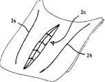
Fig. 1 illustrates a modular housing plate 1 of automobile.The modular housing plate 1 of Fig. 1 is one " door skin "." afterwards " a moulding projection 2 is worked in the modular housing plate 1, this also will explain in detail by means of subsequent drawings.
Fig. 2 illustrates the profile of outer casing member shown in Figure 11 along hatching A-A.The length of moulding projection 2 is l, and the degree of depth is t.The degree of depth t of moulding projection 2 reaches its maximum in the z of Fig. 2 axle zone, and reduces gradually towards the end of moulding projection 2.
Fig. 3 illustrates the profile of outer casing member 1 along the hatching B-B of Fig. 1.Be apparent that moulding projection 2 is relative wedge angles.Strong so outstanding characteristic curve is very difficult or may not create with traditional method for drawing.
Fig. 4 has illustrated to describe the finishing process of modular housing spare 1.Modular housing spare 1 is clamped in the clamping device that does not show in detail here 3 or is fixed on the clamping device 3.Among the embodiment that illustrates here, have only the fringe region of outer casing member 1 to be fixed on the clamping device 3.And then a forming core shaft 4 is moved on the modular housing spare 1, and pushes modular housing spare 1 with predetermined thrust.In next step, forming core shaft 4 moves with respect to the direction of modular housing spare 1 along arrow 5.Forming core shaft 4 carries out " feed motion " with respect to modular housing spare 1 simultaneously, top 6 of moulding projection 2 usefulness forming core shafts 4 is pressed in the modular housing spare 1 thus.
Fig. 5 illustrates an embodiment, wherein by means of the support 7 of a die shape from modular housing spare 1 with forming core shaft 4 opposed those side back-pressure outer casing members.Be support 7 supportings of outer casing member 1 by the die shape.This profile that makes no problem ground make wedge angle as shown in Figure 5 becomes possibility.The support of die shape can be mould or " the omnipotent mould " of a member special use, and the latter also can use in the personalization of other batch casing components is produced.
Fig. 6-8 illustrates varying cross-section figure A-A, B-B and the C-C that afterwards is pressed into the moulding projection 2 in the modular housing spare 1.
Fig. 6 b illustrates along the cross-sectional view of hatching A-A.Fig. 6 a, 6b illustrate an embodiment, and one of them outstanding strongly moulding projection 2 is pressed in the modular housing spare 1 afterwards, and " top " of wherein moulding projection 2 be rounding mildly.
Fig. 7 b illustrates cross section B-B.Moulding projection 2 is outstanding slightly in this zone." top " of moulding projection 2 compared with Fig. 6 b here has bigger radius of curvature.
Fig. 8 b illustrates cross section C-C.Moulding projection 2 is stronger outstanding in this zone.Similar to Fig. 6 b, " top " of moulding projection 2 has less relatively radius of curvature.
Fig. 9 illustrates an embodiment, wherein in the finishing process support 8,9 of two substantially the same width from forming core shaft 4 opposed those side bearing modular housing spares 1.Profile with the modular housing spare before Reference numeral 1 ' the represent finishing." top " of forming core shaft 4 is more outstanding than forming core shaft shown in Figure 10 4 here.Support 8 is arranged to and " the top partition distance L1 of " center " or forming core shaft 4, the support 9 partition distance L2 of moulding projection to be made.Therefore the distance L 3 between the support 8,9 equals the summation of distance L 1 and L2.L1 is here less than L2.So support the top position with respect to forming core shaft 4 asymmetricly.Can change the supporting or the clamped condition of modular housing spare 1 by changing distance L 1, L2 or L3, and also can change the shape of moulding projection to be made thus according to condition.
Figure 10 illustrates an embodiment, and its medium-height trestle 8 is wideer than support 9.Only slightly support with respect to the top of forming core shaft 4 here asymmetricly.Be that L1 only is a bit larger tham L2 here.Compare the top more blunt of forming core shaft 4 here with Fig. 9, produce a corresponding outstanding slightly moulding projection like this.
Figure 11 illustrates an embodiment, and its medium- height trestle 8,9 is arranged to be spaced from each other a less distance L 3 mutually.As can obviously finding out from accompanying drawing, this makes relatively large degree of deformation and produces stronger outstanding moulding projection becomes possibility.
Figure 12 illustrates the mobile alignment of shaping jig, is example with a modular housing spare 1 as hood, compacting two characteristic curve 2a, 2b on this hood.From a spatial point 10, this spatial point is called " starting point " of moving movement here, and the shaping jig (not shown) at first drops on the modular housing spare 1.Shaping jig is pressed under the situation of modular housing spare 1 and is moved along characteristic curve 2a to be made applying a suitable thrust then.Be enhanced producing characteristic curve 2a aftershaping instrument, and arrive spatial point 11.Shaping jig moves to spatial point 12 from there.And then it drops on the modular housing spare 1 again, and moves along characteristic curve 2b to be made.Be enhanced producing characteristic curve 2b aftershaping instrument, and arrive spatial point 13.
Figure 13 is illustrated in " hood " 1 that produces the Figure 12 behind characteristic curve 2a and the 2b.According to identical method a central protuberance 2c is pressed on the engine hood panel in addition, this projection hood protruding upward, in Fig. 6-8, show similar.
Figure 14 illustrates a die 14, and this die is used to make a moulding projection, as the moulding projection 2c of Figure 13.Die 14 is pressed towards modular housing spare (not shown at this), and be from shaping jig 4 opposed those sides.Die 14 is used to bear part and is applied to power on the modular housing spare from shaping jig 4.Die 14 can to similar the taking the shape of the letter U that show among Figure 14, just a side opening.It also can seal in addition, and caing be compared to is a flat board that has a slotted hole.But the present invention is limited to certain die shape anything but, but comprises all die shapes.As ise apparent from FIG. 14, the interior seamed edge of die 14 tiltedly scabbles in that shaping jig 4 " entering the zone " is lean-in.Opposite inward flange is substantially perpendicular to the bearing- surface 17,18 of die 14 in the side regions 16 of die 14, and these bearing-surfaces " from following " in the finishing process are pressed to modular housing spare, and bear the power that is applied by shaping jig at this.Need mention the mobile alignment 19 of shaping jig for the reason of integrality, it extends at the center of two sides of die 14 basically.
Claims (33)
1. a manufacturing is used for the method for the outer casing member of automobile, wherein, three-dimensional preformed semifinished or finished goods standard component (1) by a vehicle that is used to produce in batches of a kind of raw material manufacturing, it is characterized in that: the outer casing member of making a kind of personalization by preformed standard component (1), its mode is, shaping jig (4) by means of a mandrel shape is pressed into a three-D profile (2) in the standard component (1) afterwards, this shaping jig to standard component (1) and move with respect to standard component (1) simultaneously, and once moves in time processing manufacturing three-D profile (2) to be made in standard component (1) afterwards by mandrel shape shaping jig (4) from a side pressure.
2. method according to claim 1 is characterized in that: raw material are a kind of sheet material, and the outer casing member of standard component (1) and manufacturing thus is respectively a plate.
3. method according to claim 1 is characterized in that: raw material are a kind of plastic materials, and the outer casing member of standard component (1) and manufacturing thus is respectively a working of plastics.
4. according to claim 1 or 3 described methods, it is characterized in that: raw material are a kind of thermoplastics.
5. method according to claim 1 is characterized in that: in the deformation process that is produced by mandrel shape shaping jig (4), standard component (1) is fixed by a clamping device in its fringe region.
6. method according to claim 5 is characterized in that: clamping device has a plurality of bites.
7. method according to claim 6 is characterized in that: some bites are set, and these bites are made of the clamping element of a sucker shape respectively, and these clamping elements fix standard component by negative pressure.
8. according to the described method of one of claim 5 to 7, it is characterized in that: in the deformation process that produces by mandrel shape shaping jig (4), standard component (1) is only fixed by clamping device in its fringe region, and neither supports also in the member region between fringe region and fix without other modes.
9. according to the described method of one of claim 5 to 7, it is characterized in that: in the deformation process that produces by mandrel shape shaping jig (4), standard component (1) is fixed by clamping device, and in the member region between fringe region at least on a position by a support (7) supporting, this support be arranged on standard component (1) with opposed that side of mandrel shape shaping jig (4) on.
10. method according to claim 9 is characterized in that: support (7) is the member of a die shape, and this member plays the effect of former with respect to three-D profile to be made.
11. method according to claim 1 is characterized in that: mandrel shape shaping jig (4) has a tool tip smooth, convex bending.
12. method according to claim 11 is characterized in that: the tool tip of mandrel shape shaping jig (4) is made of the spheroid of a rotatable supporting, and this spheroid is gone up rolling at standard component (1) when processing criterion part (1).
13. method according to claim 1, it is characterized in that: mandrel shape shaping jig (4) has an adjustable tool tip, and the width of this tool tip moving direction transverse to mandrel shape shaping jig (4) in process changes with respect to standard component (1).
14., it is characterized in that: in the deformation process of standard component (1), in the tool tip zone, mandrel shape shaping jig is heated at least according to the described method of one of claim 11 to 13.
15. method according to claim 1 is characterized in that: standard component (1) is heated by a thermal source in deformation process or is heated.
16. method according to claim 1 is characterized in that: shaping jig longitudinal axis around shaping jig in the deformation process of standard component (1) rotates.
17. method according to claim 1 is characterized in that: forming core shaft longitudinal axis around forming core shaft in the deformation process of standard component (1) vibrates.
18. method according to claim 1 is characterized in that: the shaping jig (4) with the mandrel shape also is pressed into some feature contours relevant with outward appearance, wire in the standard component (1).
19. according to claim 1,2 or 5 described methods, it is characterized in that: standard component is a rolled-up stock, and this rolled-up stock is made by means of a compression moulding instrument.
20. according to claim 1,2 or 5 described methods, it is characterized in that: standard component is a plate of making by the pull and stretch mode.
21. method according to claim 1 is characterized in that: the three-D profile that has existed in standard component carries out finishing by pull and stretch or intensification again by the shaping jig (4) with the mandrel shape.
22. method according to claim 1 is characterized in that: standard component (1) is protecgulum, bonnet, car door, gusset spare, beater or beat-up or a roof.
23. method according to claim 1 is characterized in that: the shaping jig of mandrel shape (4) is arranged on the arm of a robot.
24. method according to claim 1 is characterized in that: the shaping jig of mandrel shape is the part of CNC lathe.
25. according to the described method of one of claim 11 to 13, it is characterized in that: in the process of processing criterion part (1), therefore the shaping jig of mandrel shape produces a kind of contact of creeping into friction that is similar to around its longitudinal axis rotation between the top and standard component (1) of forming core shaft.
26. method according to claim 8, it is characterized in that: standard component (1) is fixed in deformation process like this, make its geometry in its fringe region not change with respect to reset condition, the standard component when just making the size for connection that obtains when after this being installed in the body in white or gap size with respect to reset condition does not change.
27. method according to claim 1 is characterized in that: standard component (1) is a modular housing spare.
28. method according to claim 1 is characterized in that: three-D profile (2) to be made is made by repeatedly moving with the increment feeding of mandrel shape shaping jig (4) in standard component (1) afterwards.
29. method according to claim 28, it is characterized in that: the shaping jig of mandrel shape (4) from finishing process to finishing process next time with respect to standard component (1) vertical feed, so that to finishing process next time profile is deepened from a finishing process.
30. according to claim 28 or 29 described methods, it is characterized in that: the shaping jig of mandrel shape (4) from a finishing process to the moving direction feeding of finishing process next time, so that to finishing process next time profile is widened from a finishing process transverse to shaping jig (4).
31. an outer casing member, it is made by the described method of one of claim 1 to 30 by a kind of standard component (1).
32. outer casing member according to claim 31 is characterized in that: standard component (1) is made by sheet material.
33. outer casing member according to claim 31 is characterized in that: standard component (1) is made of plastics.
Applications Claiming Priority (2)
| Application Number | Priority Date | Filing Date | Title |
|---|---|---|---|
| DE10324244.9 | 2003-05-28 | ||
| DE10324244A DE10324244A1 (en) | 2003-05-28 | 2003-05-28 | Process for the production of individualized outer skin sheet metal parts from series production of outer skin sheet metal parts for vehicles as well as outer skin sheet metal parts manufactured according to this process |
Publications (2)
| Publication Number | Publication Date |
|---|---|
| CN1795066A CN1795066A (en) | 2006-06-28 |
| CN100382910C true CN100382910C (en) | 2008-04-23 |
Family
ID=33482249
Family Applications (1)
| Application Number | Title | Priority Date | Filing Date |
|---|---|---|---|
| CNB2004800144869A Expired - Lifetime CN100382910C (en) | 2003-05-28 | 2004-02-14 | Method of producing individualized vehicle parts, particularly individualized vehicle body skin parts consisting of series-produced vehicle body skin parts, as well as vehicle body skin parts manufact |
Country Status (8)
| Country | Link |
|---|---|
| US (1) | US20060090530A1 (en) |
| EP (1) | EP1626824B1 (en) |
| JP (1) | JP2007512960A (en) |
| KR (1) | KR20060014060A (en) |
| CN (1) | CN100382910C (en) |
| DE (2) | DE10324244A1 (en) |
| ES (1) | ES2309499T3 (en) |
| WO (1) | WO2004105976A1 (en) |
Families Citing this family (17)
| Publication number | Priority date | Publication date | Assignee | Title |
|---|---|---|---|---|
| DE102005024378B4 (en) * | 2005-05-27 | 2016-02-18 | Fraunhofer-Gesellschaft zur Förderung der angewandten Forschung e.V. | Method for incremental forming of thin-walled workpieces and device |
| DE102005048220C5 (en) * | 2005-09-29 | 2018-01-18 | Magna Exteriors (Germany) Gmbh | Method for producing a trim part variant for a motor vehicle and trim part |
| DE102006016460A1 (en) * | 2006-04-07 | 2007-10-11 | Bayerische Motoren Werke Ag | Device for processing sheet metal in the manufacture of outer skin parts for vehicles comprises a drive unit which rotates a tool holder and a deforming tool having a middle longitudinal axis which is offset from the axis of rotation |
| DE102007009705B3 (en) * | 2007-02-28 | 2007-10-31 | Audi Ag | Press tool assembly for automotive body panels has standard base frame for clamp and standard base frame for press tool |
| DE102008004051A1 (en) | 2008-01-11 | 2009-07-16 | Bayerische Motoren Werke Aktiengesellschaft | A method of forming a sheet metal part and apparatus for carrying out the method |
| DE102008016999A1 (en) * | 2008-04-03 | 2009-10-08 | Bayerische Motoren Werke Aktiengesellschaft | Tool for postforming deep-drawn sheet metal part for body of motor vehicle, has embossing die supported in press base or pressure pad and moved from withdrawn position to plunged position in sheet metal part |
| CN102000722A (en) * | 2009-08-31 | 2011-04-06 | 扬州恒德模具有限公司 | Upper rolling-rib die for rotating station of numerically-controlled turret punch |
| US8783078B2 (en) | 2010-07-27 | 2014-07-22 | Ford Global Technologies, Llc | Method to improve geometrical accuracy of an incrementally formed workpiece |
| JP5696682B2 (en) * | 2012-04-05 | 2015-04-08 | トヨタ自動車株式会社 | Metal plate forming method |
| JP6072433B2 (en) * | 2012-05-23 | 2017-02-01 | 株式会社アミノ | Sequential molding method and apparatus |
| DE102014006683A1 (en) | 2014-05-08 | 2015-11-12 | GM Global Technology Operations LLC (n. d. Gesetzen des Staates Delaware) | Production line for processing at least one surface component and method for processing the at least one surface component in the production line |
| DE102014219021A1 (en) * | 2014-09-22 | 2016-03-24 | Volkswagen Aktiengesellschaft | press tool |
| DE102014221878A1 (en) | 2014-10-28 | 2016-04-28 | Bayerische Motoren Werke Aktiengesellschaft | Press tool for producing a sheet metal part having at least one sharp-edged sheet metal part edge and sheet metal part produced therewith |
| US20180214927A1 (en) * | 2017-01-31 | 2018-08-02 | Ford Motor Company | Method for production of sheet metal components |
| EP3648908A1 (en) * | 2017-07-06 | 2020-05-13 | Bobst Mex Sa | A method of creasing sheets |
| US11628484B2 (en) * | 2019-03-28 | 2023-04-18 | Honda Motor Co., Ltd. | Press forming method |
| CN111114649B (en) * | 2019-11-28 | 2023-10-20 | 无锡曙光模具有限公司 | Automobile engine cabin covering shell part and processing technology thereof |
Citations (5)
| Publication number | Priority date | Publication date | Assignee | Title |
|---|---|---|---|---|
| CN2053203U (en) * | 1989-04-04 | 1990-02-21 | 沈阳重型机器厂 | Vacuum suction cup |
| DE4034625A1 (en) * | 1990-10-31 | 1992-05-07 | Doege Eckart | DRAWING PROCEDURE |
| US6216508B1 (en) * | 1998-01-29 | 2001-04-17 | Amino Corporation | Apparatus for dieless forming plate materials |
| JP2002102944A (en) * | 2000-09-25 | 2002-04-09 | Honda Motor Co Ltd | Incremental stretch forming method |
| JP2003053436A (en) * | 2001-08-08 | 2003-02-26 | Amino:Kk | Dieless sheet forming method and device |
Family Cites Families (12)
| Publication number | Priority date | Publication date | Assignee | Title |
|---|---|---|---|---|
| US1899347A (en) * | 1929-05-15 | 1933-02-28 | Clark Equipment Co | Axle |
| US2560822A (en) * | 1945-11-08 | 1951-07-17 | Walton S Robinson | Means and method for making seamless pipe elbows |
| US2556738A (en) * | 1949-04-21 | 1951-06-12 | City Auto Stamping Co | Method of forming automobile body fenders |
| US3966260A (en) * | 1975-01-07 | 1976-06-29 | Eaton Corporation | Prestressed axle beam |
| EP0299111B1 (en) * | 1987-07-13 | 1994-06-01 | Wilhelm Hegenscheidt Gesellschaft mbH | Method and apparatus for straightening unbalanced workpieces |
| DE4208160A1 (en) * | 1992-03-13 | 1993-09-16 | Zeppelin Metallwerke Gmbh | Press used for shaping metal - has workpiece tensioned on peripheral side and given necessary bend by pressure roller, roller and workpiece moving w.r.t. one another. |
| JP3475551B2 (en) * | 1995-02-27 | 2003-12-08 | 松下電器産業株式会社 | Shaft forming method from metal plate |
| JP3753608B2 (en) * | 2000-04-17 | 2006-03-08 | 株式会社日立製作所 | Sequential molding method and apparatus |
| US6532786B1 (en) * | 2000-04-19 | 2003-03-18 | D-J Engineering, Inc. | Numerically controlled forming method |
| DE10119839C2 (en) * | 2001-04-23 | 2003-09-11 | Benteler Automobiltechnik Gmbh | Method for manufacturing an axle element for motor vehicles |
| DE10135561C1 (en) * | 2001-07-20 | 2003-03-13 | Audi Ag | Special model bodywork component manufacturing process, for vehicle, involves deep drawing and deforming under pressure |
| US6668612B2 (en) * | 2002-02-21 | 2003-12-30 | General Motors Corporation | Device for holding a sheet metal blank in a forming press |
-
2003
- 2003-05-28 DE DE10324244A patent/DE10324244A1/en not_active Ceased
-
2004
- 2004-02-14 JP JP2006529659A patent/JP2007512960A/en active Pending
- 2004-02-14 EP EP04711311A patent/EP1626824B1/en not_active Expired - Lifetime
- 2004-02-14 WO PCT/EP2004/001403 patent/WO2004105976A1/en active IP Right Grant
- 2004-02-14 KR KR1020057022445A patent/KR20060014060A/en not_active Application Discontinuation
- 2004-02-14 CN CNB2004800144869A patent/CN100382910C/en not_active Expired - Lifetime
- 2004-02-14 ES ES04711311T patent/ES2309499T3/en not_active Expired - Lifetime
- 2004-02-14 DE DE502004007843T patent/DE502004007843D1/en not_active Expired - Lifetime
-
2005
- 2005-11-28 US US11/287,203 patent/US20060090530A1/en not_active Abandoned
Patent Citations (5)
| Publication number | Priority date | Publication date | Assignee | Title |
|---|---|---|---|---|
| CN2053203U (en) * | 1989-04-04 | 1990-02-21 | 沈阳重型机器厂 | Vacuum suction cup |
| DE4034625A1 (en) * | 1990-10-31 | 1992-05-07 | Doege Eckart | DRAWING PROCEDURE |
| US6216508B1 (en) * | 1998-01-29 | 2001-04-17 | Amino Corporation | Apparatus for dieless forming plate materials |
| JP2002102944A (en) * | 2000-09-25 | 2002-04-09 | Honda Motor Co Ltd | Incremental stretch forming method |
| JP2003053436A (en) * | 2001-08-08 | 2003-02-26 | Amino:Kk | Dieless sheet forming method and device |
Also Published As
| Publication number | Publication date |
|---|---|
| US20060090530A1 (en) | 2006-05-04 |
| JP2007512960A (en) | 2007-05-24 |
| CN1795066A (en) | 2006-06-28 |
| EP1626824B1 (en) | 2008-08-13 |
| KR20060014060A (en) | 2006-02-14 |
| EP1626824A1 (en) | 2006-02-22 |
| DE10324244A1 (en) | 2004-12-30 |
| WO2004105976A1 (en) | 2004-12-09 |
| ES2309499T3 (en) | 2008-12-16 |
| DE502004007843D1 (en) | 2008-09-25 |
Similar Documents
| Publication | Publication Date | Title |
|---|---|---|
| CN100382910C (en) | Method of producing individualized vehicle parts, particularly individualized vehicle body skin parts consisting of series-produced vehicle body skin parts, as well as vehicle body skin parts manufact | |
| CN100471594C (en) | Method and apparatus for forming sheet metal | |
| CN100564006C (en) | Stir forming apparatus and method | |
| US7654124B2 (en) | Method of making a sheet metal part for motor vehicles | |
| EP1173299A1 (en) | Automated method and device for the non-cutting shaping of a body | |
| CN104487188B (en) | The manufacture method of die forging bent axle | |
| WO2009123538A1 (en) | Method of manufacturing a press-formed sheet-metal product | |
| JPH10510615A (en) | Method of manufacturing a joint housing | |
| US20070234859A1 (en) | Method of Punching an Opening into a Work Piece | |
| US9375778B2 (en) | Method for forming forged parts | |
| RU2353498C2 (en) | Method for manufacture of ball journals by cold plastic working | |
| CN105108460B (en) | Manufacturing method of cam plate with no need for grinding of outer contour | |
| CN106734443A (en) | Back-shaped groove framework processing method and a kind of series connection insert splicing bending mould | |
| KR100455081B1 (en) | A housing forming method | |
| Merklein et al. | Sheet-bulk metal forming–forming of functional components from sheet metals | |
| KR102435358B1 (en) | A method for producing a rotationally symmetrical shaped article | |
| CN104043764B (en) | Forging processing method and device thereof | |
| KR20010073024A (en) | Method for producing a gear rack, and a stamping device for carrying out the method | |
| CN108941318B (en) | Mirror image dieless machining method for metal sheet metal part | |
| JP2010504213A (en) | Method for forming hollow member | |
| Nakagawa | Recent manufacturing technologies for auto-body panel forming tools | |
| CN111699058B (en) | Forming tool and method for producing an edge on a component and method for producing such a forming tool | |
| JP2711156B2 (en) | Mold for stamping sheet metal parts | |
| Ruban et al. | Implementation of design for manufacturing in hot forging | |
| KR20230170405A (en) | progressive mold and shaving structure |
Legal Events
| Date | Code | Title | Description |
|---|---|---|---|
| C06 | Publication | ||
| PB01 | Publication | ||
| C10 | Entry into substantive examination | ||
| SE01 | Entry into force of request for substantive examination | ||
| C14 | Grant of patent or utility model | ||
| GR01 | Patent grant | ||
| CX01 | Expiry of patent term | ||
| CX01 | Expiry of patent term |
Granted publication date: 20080423 |