BRPI0919836B1 - MULTIPLE VORTEX SEPARATOR AND METHOD OF REMOVING AN AIR FLOW - Google Patents
MULTIPLE VORTEX SEPARATOR AND METHOD OF REMOVING AN AIR FLOW Download PDFInfo
- Publication number
- BRPI0919836B1 BRPI0919836B1 BRPI0919836-9A BRPI0919836A BRPI0919836B1 BR PI0919836 B1 BRPI0919836 B1 BR PI0919836B1 BR PI0919836 A BRPI0919836 A BR PI0919836A BR PI0919836 B1 BRPI0919836 B1 BR PI0919836B1
- Authority
- BR
- Brazil
- Prior art keywords
- refuse
- separator
- vortex separator
- multiple vortex
- conical cavity
- Prior art date
Links
Images


Classifications
-
- B—PERFORMING OPERATIONS; TRANSPORTING
- B04—CENTRIFUGAL APPARATUS OR MACHINES FOR CARRYING-OUT PHYSICAL OR CHEMICAL PROCESSES
- B04C—APPARATUS USING FREE VORTEX FLOW, e.g. CYCLONES
- B04C5/00—Apparatus in which the axial direction of the vortex is reversed
- B04C5/02—Construction of inlets by which the vortex flow is generated, e.g. tangential admission, the fluid flow being forced to follow a downward path by spirally wound bulkheads, or with slightly downwardly-directed tangential admission
- B04C5/04—Tangential inlets
-
- B—PERFORMING OPERATIONS; TRANSPORTING
- B01—PHYSICAL OR CHEMICAL PROCESSES OR APPARATUS IN GENERAL
- B01D—SEPARATION
- B01D45/00—Separating dispersed particles from gases or vapours by gravity, inertia, or centrifugal forces
- B01D45/12—Separating dispersed particles from gases or vapours by gravity, inertia, or centrifugal forces by centrifugal forces
-
- B—PERFORMING OPERATIONS; TRANSPORTING
- B01—PHYSICAL OR CHEMICAL PROCESSES OR APPARATUS IN GENERAL
- B01D—SEPARATION
- B01D50/00—Combinations of methods or devices for separating particles from gases or vapours
- B01D50/20—Combinations of devices covered by groups B01D45/00 and B01D46/00
-
- B—PERFORMING OPERATIONS; TRANSPORTING
- B04—CENTRIFUGAL APPARATUS OR MACHINES FOR CARRYING-OUT PHYSICAL OR CHEMICAL PROCESSES
- B04C—APPARATUS USING FREE VORTEX FLOW, e.g. CYCLONES
- B04C5/00—Apparatus in which the axial direction of the vortex is reversed
- B04C5/12—Construction of the overflow ducting, e.g. diffusing or spiral exits
- B04C5/13—Construction of the overflow ducting, e.g. diffusing or spiral exits formed as a vortex finder and extending into the vortex chamber; Discharge from vortex finder otherwise than at the top of the cyclone; Devices for controlling the overflow
-
- B—PERFORMING OPERATIONS; TRANSPORTING
- B04—CENTRIFUGAL APPARATUS OR MACHINES FOR CARRYING-OUT PHYSICAL OR CHEMICAL PROCESSES
- B04C—APPARATUS USING FREE VORTEX FLOW, e.g. CYCLONES
- B04C5/00—Apparatus in which the axial direction of the vortex is reversed
- B04C5/14—Construction of the underflow ducting; Apex constructions; Discharge arrangements ; discharge through sidewall provided with a few slits or perforations
- B04C5/15—Construction of the underflow ducting; Apex constructions; Discharge arrangements ; discharge through sidewall provided with a few slits or perforations with swinging flaps or revolving sluices; Sluices; Check-valves
-
- B—PERFORMING OPERATIONS; TRANSPORTING
- B04—CENTRIFUGAL APPARATUS OR MACHINES FOR CARRYING-OUT PHYSICAL OR CHEMICAL PROCESSES
- B04C—APPARATUS USING FREE VORTEX FLOW, e.g. CYCLONES
- B04C5/00—Apparatus in which the axial direction of the vortex is reversed
- B04C5/24—Multiple arrangement thereof
- B04C5/26—Multiple arrangement thereof for series flow
-
- B—PERFORMING OPERATIONS; TRANSPORTING
- B04—CENTRIFUGAL APPARATUS OR MACHINES FOR CARRYING-OUT PHYSICAL OR CHEMICAL PROCESSES
- B04C—APPARATUS USING FREE VORTEX FLOW, e.g. CYCLONES
- B04C9/00—Combinations with other devices, e.g. fans, expansion chambers, diffusors, water locks
-
- B—PERFORMING OPERATIONS; TRANSPORTING
- B64—AIRCRAFT; AVIATION; COSMONAUTICS
- B64D—EQUIPMENT FOR FITTING IN OR TO AIRCRAFT; FLIGHT SUITS; PARACHUTES; ARRANGEMENTS OR MOUNTING OF POWER PLANTS OR PROPULSION TRANSMISSIONS IN AIRCRAFT
- B64D11/00—Passenger or crew accommodation; Flight-deck installations not otherwise provided for
- B64D11/02—Toilet fittings
-
- B—PERFORMING OPERATIONS; TRANSPORTING
- B04—CENTRIFUGAL APPARATUS OR MACHINES FOR CARRYING-OUT PHYSICAL OR CHEMICAL PROCESSES
- B04C—APPARATUS USING FREE VORTEX FLOW, e.g. CYCLONES
- B04C5/00—Apparatus in which the axial direction of the vortex is reversed
- B04C5/12—Construction of the overflow ducting, e.g. diffusing or spiral exits
- B04C5/13—Construction of the overflow ducting, e.g. diffusing or spiral exits formed as a vortex finder and extending into the vortex chamber; Discharge from vortex finder otherwise than at the top of the cyclone; Devices for controlling the overflow
- B04C2005/136—Baffles in the vortex finder
-
- B—PERFORMING OPERATIONS; TRANSPORTING
- B04—CENTRIFUGAL APPARATUS OR MACHINES FOR CARRYING-OUT PHYSICAL OR CHEMICAL PROCESSES
- B04C—APPARATUS USING FREE VORTEX FLOW, e.g. CYCLONES
- B04C9/00—Combinations with other devices, e.g. fans, expansion chambers, diffusors, water locks
- B04C2009/004—Combinations with other devices, e.g. fans, expansion chambers, diffusors, water locks with internal filters, in the cyclone chamber or in the vortex finder
-
- Y—GENERAL TAGGING OF NEW TECHNOLOGICAL DEVELOPMENTS; GENERAL TAGGING OF CROSS-SECTIONAL TECHNOLOGIES SPANNING OVER SEVERAL SECTIONS OF THE IPC; TECHNICAL SUBJECTS COVERED BY FORMER USPC CROSS-REFERENCE ART COLLECTIONS [XRACs] AND DIGESTS
- Y02—TECHNOLOGIES OR APPLICATIONS FOR MITIGATION OR ADAPTATION AGAINST CLIMATE CHANGE
- Y02T—CLIMATE CHANGE MITIGATION TECHNOLOGIES RELATED TO TRANSPORTATION
- Y02T50/00—Aeronautics or air transport
- Y02T50/40—Weight reduction
-
- Y—GENERAL TAGGING OF NEW TECHNOLOGICAL DEVELOPMENTS; GENERAL TAGGING OF CROSS-SECTIONAL TECHNOLOGIES SPANNING OVER SEVERAL SECTIONS OF THE IPC; TECHNICAL SUBJECTS COVERED BY FORMER USPC CROSS-REFERENCE ART COLLECTIONS [XRACs] AND DIGESTS
- Y10—TECHNICAL SUBJECTS COVERED BY FORMER USPC
- Y10S—TECHNICAL SUBJECTS COVERED BY FORMER USPC CROSS-REFERENCE ART COLLECTIONS [XRACs] AND DIGESTS
- Y10S4/00—Baths, closets, sinks, and spittoons
- Y10S4/19—Liquid-solid separators
Abstract
equipamento de vórtice separador de refugo. um separador de vórtice para puxar um fluxo de ar substancialmente sem umidade a partir de um fluxo de refugo tendo um canal anular definindo um primeiro percurso de fluxo de vórtice para separar refugo líquido e sólido a partir desse fluxo de refugo e preferivelmente uma unidade de filtro com uma cavidade cônica invertida entre cones invertidos encaixados definindo um segundo percurso de fluxo de vórtice que é isolado do primeiro percurso de fluxo de vórtice para separar refugo líquido e sólido adicional a partir do fluxo de refugo antes de ele sair do separador de vórtice. em modalidades preferidas, o separador inclui um cartucho de unidade de filtro removível posicionado dentro do cone externo e um isolador em espiral para respectivamente fazer o uso do separador mais conveniente e mais eficiente.scrap separator vortex equipment. a vortex separator for pulling a substantially moisture-free air stream from a refuse stream having an annular channel defining a first vortex flow path to separate liquid and solid refuse from that refuse stream and preferably a filter unit with an inverted conical cavity between fitted inverted cones defining a second vortex flow path that is isolated from the first vortex flow path to separate additional liquid and solid waste from the waste stream before it exits the vortex separator. in preferred embodiments, the separator includes a removable filter unit cartridge positioned inside the outer cone and a spiral insulator to respectively make the use of the separator more convenient and more efficient.
Description
Esta invenção se refere aos sistemas para separar refugo de avião e, mais especificamente, a um equipamento de vórtice para remover refugo sólido e líquido a partir de um fluxo de refugo a partir de privadas ou outros receptáculos de avião enquanto retirando um fluxo de ar substancialmente livre de umidade sob sucção.This invention relates to systems for separating plane refuse and, more specifically, to vortex equipment for removing solid and liquid refuse from a refuse stream from toilets or other aircraft receptacles while substantially removing an air stream. free of moisture under suction.
Vários sistemas estão disponíveis na técnica os quais empregam um vácuo para suportar material de refugo líquido e sólido a partir de privadas de avião ou outros receptáculos para um tanque de refugo para armazenamento. 0 material de refugo que é transportado inclui excremento humano sólido, urina, água, opcionalmente substâncias químicas de limpeza e desinfetantes, ar, papel higiênico, alimento e frequentemente artigos descartados inesperados, todos os quais são retirados das privadas do avião ou outros receptáculos para um ou mais tanques de refugo. Os tanques de refugo, evidentemente, são esvaziados durante manutenção do avião no solo.Various systems are available in the art which employ a vacuum to support liquid and solid waste material from aircraft toilets or other receptacles for a refuse tank for storage. The refuse material that is transported includes solid human excrement, urine, water, optionally cleaning chemicals and disinfectants, air, toilet paper, food and often unexpected discarded items, all of which are taken from the toilet bowls or other receptacles to a or more refuse tanks. The refuse tanks, of course, are emptied during the aircraft's maintenance on the ground.
A sucção que transporta o material de refugo para um tanque de refugo normalmente é provida por um gerador de vácuo quando o avião está no solo ou em baixas altitudes. Em altitudes mais altas, o sistema tipicamente será ventilado para a atmosfera externa de pressão inferior, criando um diferencial de pressão entre a atmosfera exterior e o interior do avião para retirar o material de refugo a partir das privadas do avião ou outros receptáculos para transporte para o tanque de refugo para armazenamento.The suction that transports the refuse material to a refuse tank is usually provided by a vacuum generator when the plane is on the ground or at low altitudes. At higher altitudes, the system will typically be vented to the lower pressure outdoor atmosphere, creating a pressure differential between the outside atmosphere and the interior of the airplane to remove the scrap material from the airplane toilets or other transport receptacles for transport. the refuse tank for storage.
Quando o material de refugo é transportado para o tanque de refugo, o ar que é retirado junto com o material de refugo deve ser liberado para a atmosfera. Esse ar deve estar livre de umidade e sólidos particulados por razões sanitárias e por segurança. No que diz respeito às preocupações sanitárias, é obviamente indesejável liberar excremento humano em partículas na atmosfera, quer seja quando o avião está no ar ou quando ele está em terra. Adicionalmente, há o perigo de que se uma quantidade substancial de água escapar do avião a partir de tal sistema de coleta de refugo do avião acionado a vácuo, o mesmo pode se acumular na fuselagem do avião para formar gelo.When the waste material is transported to the waste tank, the air that is removed with the waste material must be released into the atmosphere. This air must be free of moisture and particulate solids for health and safety reasons. With regard to health concerns, it is obviously undesirable to release particulate human excrement into the atmosphere, either when the plane is in the air or when it is on the ground. Additionally, there is a danger that if a substantial amount of water escapes from the aircraft from such a vacuum-driven aircraft refuse collection system, it may accumulate in the aircraft's fuselage to form ice.
Os sistemas de separação de material de refugo de avião, convencionais, são grandes e assim exigem espaço excessivo no avião enquanto contribuindo desnecessariamente para o peso do avião, reduzindo a sua eficiência de combustível. Além disso, os sistemas convencionais de separação de material de refugo requerem manutenção frequente, o que frequentemente é difícil e demorado devido ao acesso inconveniente ao equipamento separador. Adicionalmente, os sistemas convencionais de separação de material de refugo tipicamente têm dois separadores, um na entrada e outro na saída dos sistemas. Finalmente, o equipamento convencional de separação, embora frequentemente eficaz na remoção de umidade a partir do material de refugo sob condições ótimas poderia, ainda assim, ser aperfeiçoado mediante garantia de que o equipamento evitasse, de forma consistente, o escape de umidade.Conventional aircraft refuse separation systems are large and thus require excessive space on the plane while contributing unnecessarily to the weight of the plane, reducing its fuel efficiency. In addition, conventional waste material separation systems require frequent maintenance, which is often difficult and time-consuming due to inconvenient access to the separator equipment. In addition, conventional waste material separation systems typically have two separators, one at the entrance and one at the exit of the systems. Finally, conventional separation equipment, although often effective in removing moisture from the waste material under optimal conditions, could still be improved by ensuring that the equipment consistently prevents moisture leakage.
Assim, existe a necessidade de um sistema de separação de material de refugo, aperfeiçoado, utilizando um único separador compondo um sistema global que é compacto e leve sem comprometer o seu desempenho. Ele deve ser efetivo de forma consistente na minimização ou prevenção do escape de umidade para o fluxo de ar de saída. Adicionalmente, o equipamento deve ser capaz de substituição fácil e segura com exposição mínima ao refugo coletado. Finalmente, o equipamento deve ser capaz de fácil instalação no espaço limitado disponível no avião. A presente invenção satisfaz todas essas exigências e também tem outras vantagens.Thus, there is a need for an improved waste material separation system, using a single separator, composing a global system that is compact and lightweight without compromising its performance. It must be consistently effective in minimizing or preventing the escape of moisture into the outlet air flow. Additionally, the equipment must be capable of easy and safe replacement with minimal exposure to the collected waste. Finally, the equipment must be capable of easy installation in the limited space available on the plane. The present invention satisfies all of these requirements and also has other advantages.
A presente invenção compreende um separador de vórtice múltiplo para retirar um fluxo de ar substancialmente livre de umidade a partir de um fluxo de refugo contendo refugo líquido e sólido. 0 separador é particularmente bem adaptado para uso em avião. 0 separador da invenção inclui um alojamento, o qual é de formato preferivelmente cilíndrico, e tem uma entrada de refugo para receber o fluxo de refugo. 0 tubo de entrada que leva à entrada de refugo preferivelmente será inclinado com relação ao plano horizontal para acrescentar um auxílio gravitacional ao fluxo de refugo que entra no separador. 0 topo do alojamento cilíndrico é encerrado e tem uma abertura de descarga para retirar o fluxo de ar substancialmente livre de umidade a partir do alojamento por intermédio da força de sucção provida pela pressão delta produzida por um gerador de vácuo ou, em elevadas altitudes, o diferencial de pressão entre a atmosfera exterior e o interior do avião.The present invention comprises a multiple vortex separator for drawing a substantially moisture-free air stream from a waste stream containing liquid and solid waste. The separator is particularly well suited for use in aircraft. The separator of the invention includes a housing, which is preferably cylindrical in shape, and has a refuse inlet to receive the refuse stream. The inlet tube leading to the refuse inlet will preferably be angled with respect to the horizontal plane to add gravitational aid to the refuse flow entering the separator. The top of the cylindrical housing is closed and has a discharge opening to remove the substantially moisture-free air flow from the housing through the suction force provided by the delta pressure produced by a vacuum generator or, at high altitudes, the pressure differential between the outside atmosphere and the interior of the airplane.
Um canal anular é posicionado ao longo da superfície interna da parede cilíndrica do alojamento. Esse canal define um primeiro percurso de vórtice para separar refugo líquido e sólido a partir do fluxo de refugo. 0 canal anular está em comunicação com a entrada de refugo.An annular channel is positioned along the inner surface of the housing's cylindrical wall. This channel defines a first vortex path to separate liquid and solid waste from the waste stream. The annular channel is in communication with the refuse input.
Uma unidade de filtro compreendendo um par de cones invertidos encaixados está localizada dentro do alojamento cilíndrico. Esses cones definem uma cavidade cônica invertida que está em comunicação com a abertura de descarga. Um segundo percurso de fluxo de vórtice que se forma dentro da cavidade cônica assim é isolado do primeiro percurso de vórtice. Em uma modalidade da invenção, a unidade de filtro pode ser configurada como um cartucho de unidade de filtro substituível.A filter unit comprising a pair of fitted inverted cones is located within the cylindrical housing. These cones define an inverted conical cavity that is in communication with the discharge opening. A second vortex flow path that forms within the conical cavity is thus isolated from the first vortex path. In one embodiment of the invention, the filter unit can be configured as a replaceable filter unit cartridge.
Consequentemente, um fluxo de refugo contendo refugo líquido e sólido é puxado para dentro do alojamento através da entrada de refugo por uma força de sucção aplicada à abertura de descarga. 0 fluxo de refugo que entra encontra o canal anular ao longo da superfície interna da parede de alojamento, se deslocando em um primeiro percurso de fluxo de vórtice no qual refugos líquidos e sólidos são separados do fluxo de refugo pela força centrífuga. Como resultado, os materiais de refugo mais pesados se deslocam para o exterior do canal anular e caem descendentemente para coleta conforme apropriado. Em uma modalidade preferida, o fluxo de ar mais leve restante entra na cavidade cônica invertida entre os cones encaixados em um segundo percurso de vórtice que é isolado do primeiro percurso de vórtice.Consequently, a waste stream containing liquid and solid waste is pulled into the housing through the waste inlet by a suction force applied to the discharge opening. The incoming refuse flow meets the annular channel along the inner surface of the housing wall, moving in a first vortex flow path in which liquid and solid wastes are separated from the refuse flow by the centrifugal force. As a result, the heavier scrap materials move outside the annular canal and fall downward for collection as appropriate. In a preferred embodiment, the lighter airflow remaining enters the inverted conical cavity between the cones fitted in a second vortex path that is isolated from the first vortex path.
Refugo líquido e sólido adicional é removido do fluxo de ar em movimento através da cavidade cônica outra vez por intermédio da força centrífuga para produzir um fluxo de ar substancialmente livre de umidade que sai do separador de vórtice através da abertura de descarga. A fonte de sucção será ou o diferencial de cabine/atmosfera em elevadas altitudes ou um gerador de vácuo em baixas altitudes.Additional liquid and solid waste is removed from the moving air flow through the tapered cavity again by means of centrifugal force to produce a substantially moisture-free air flow out of the vortex separator through the discharge opening. The suction source will be either the cabin / atmosphere differential at high altitudes or a vacuum generator at low altitudes.
Finalmente, um isolador em espiral pode ser provido na área externa da unidade de filtro para ajudar a impedir contaminação cruzada do fluxo de refugo caindo para o tanque de refugo para coleta e posterior descarte e o fluxo de ar substancialmente livre de refugo mais leve avançando para a unidade de filtro. 0 separador helicoidal inclui um elemento central oco fixado fora da unidade de filtro com um par de pás helicoidais se estendendo para fora da superfície interna do separador e defletores nas pás e na entrada para o elemento central para capturar e direcionar o refugo líquido e sólido no sentido para baixo enquanto bloqueando seu movimento no sentido para cima.Finally, a spiral insulator can be provided on the outside of the filter unit to help prevent cross contamination of the waste stream falling into the waste tank for collection and later disposal and the lighter, substantially litter-free air flow advancing to the filter unit. The helical separator includes a hollow central element fixed outside the filter unit with a pair of helical blades extending outside the inner surface of the separator and deflectors on the blades and at the entrance to the central element to capture and direct liquid and solid waste in the downwards while blocking its upward movement.
Em uma modalidade preferida, pás radialmente dispostas são posicionadas adjacentes à entrada da cavidade cônica. Essas pás são inclinadas em torno de seus eixos radiais para formar fendas angulares para induzir e aperfeiçoar o movimento giratório no fluxo de ar passando através das fendas para dentro da cavidade cônica.In a preferred embodiment, radially arranged blades are positioned adjacent to the entrance of the conical cavity. These blades are angled around their radial axes to form angular slits to induce and perfect the rotational movement in the air flow passing through the slits into the conical cavity.
A superfície interna do cone interno define uma câmara cônica interna. Uma barreira se estende entre os cones formando um fecho superior da cavidade cônica. Finalmente, ao menos uma abertura de interconexão está localizada nesse fecho superior se comunicando entre a cavidade cônica e a câmara cônica interna. Assim, o fluxo de ar se deslocando através do separador passa a partir da cavidade cônica para dentro da câmara cônica interna através da abertura de ligação.The inner surface of the inner cone defines an inner conical chamber. A barrier extends between the cones forming an upper closure of the conical cavity. Finally, at least one interconnection opening is located in this upper closure communicating between the conical cavity and the internal conical chamber. Thus, the air flow moving through the separator passes from the conical cavity into the internal conical chamber through the connection opening.
A câmara cônica interna pode ter uma válvula de retenção em sua parte inferior adaptada para abrir quando o separador não estiver puxando o fluxo de refugo para dentro do alojamento cilíndrico. Quando isso acontece, refugo líquido e sólido que se juntou na câmara cônica interna cairá a partir da câmara para ser coletado conforme apropriado. Além disso, um meio de filtro pode ser disposto na câmara para coalescer a umidade permanecendo no fluxo de ar que passa através da câmara.The internal conical chamber may have a check valve at its bottom adapted to open when the separator is not pulling the waste stream into the cylindrical housing. When this happens, liquid and solid waste that has joined in the internal conical chamber will fall from the chamber to be collected as appropriate. In addition, a filter medium can be arranged in the chamber to coalesce moisture while remaining in the air stream that passes through the chamber.
Finalmente, um elemento de descarga pode ser geralmente centrado na câmara cônica. 0 elemento de descarga tem uma prateleira anular posicionada acima da câmara e do fecho superior dos cones. 0 mesmo também tem uma porção tubular central que se projeta no sentido para baixo para dentro da câmara definindo um conduto de saída conduzindo a partir da câmara para o topo do alojamento cilíndrico do separador. Assim, o fluxo de ar saindo da câmara passará através da porção tubular antes de ser removido a partir do topo do alojamento por intermédio da abertura de descarga. Finalmente, um filtro desembaçador pode ser disposto através da abertura superior da porção tubular para ajudar a remover qualquer umidade restante no fluxo de ar de saída.Finally, a discharge element can generally be centered in the conical chamber. The discharge element has an annular shelf positioned above the chamber and the top closure of the cones. It also has a central tubular portion that projects downward into the chamber defining an outlet conduit leading from the chamber to the top of the separator cylindrical housing. Thus, the air flow from the chamber will pass through the tubular portion before being removed from the top of the housing through the discharge opening. Finally, a defroster filter can be arranged through the top opening of the tubular portion to help remove any remaining moisture in the outlet air flow.
Para auxiliar no entendimento da invenção, a mesma será descrita agora em conexão com suas modalidades exemplares com referência aos desenhos anexos nos quais designações numéricas semelhantes serão dadas aos aspectos semelhantes com referência aos desenhos anexos em que:To assist in understanding the invention, it will now be described in connection with its exemplary modalities with reference to the attached drawings in which similar numerical designations will be given to similar aspects with reference to the attached drawings in which:
A Figura 1 é uma vista em perspectiva do exterior de um tanque de refugo adaptado com um separador de vórtice de acordo com a presente invenção;Figure 1 is a perspective view from the outside of a refuse tank adapted with a vortex separator according to the present invention;
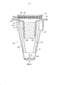
A Figura 2 é uma vista destacada parcial do separador de vórtice e tanque de refugo da Figura 1;Figure 2 is a partial detached view of the vortex separator and refuse tank of Figure 1;
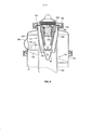
A Figura 3 é uma vista ampliada do separador de vórtice da Figura 1;Figure 3 is an enlarged view of the vortex separator of Figure 1;
A Figura 4 é uma vista em elevação destacada de um cartucho de unidade de filtro substituível que pode ser usado na prática da presente invenção;Figure 4 is a raised elevation view of a replaceable filter unit cartridge that can be used in the practice of the present invention;
A Figura 5 é uma vista explodida do cartucho de unidade de filtro da Figura 4;Figure 5 is an exploded view of the filter unit cartridge of Figure 4;
A Figura 6 é uma vista em perspectiva destacada de um separador de vórtice e tanque de refugo de acordo com a invenção tendo um cartucho de unidade de filtro no lugar;Figure 6 is an exploded perspective view of a vortex separator and refuse tank according to the invention having a filter unit cartridge in place;
A Figura 7 é uma vista em elevação lateral do exterior de um separador de vórtice e tanque de refugo de acordo com a invenção mostrando o tubo de entrada inclinado;Figure 7 is a side elevation view of the exterior of a vortex separator and refuse tank according to the invention showing the angled inlet pipe;
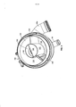
A Figura 8 é uma vista em elevação destacada do separador de vórtice e tanque de refugo da Figura 7 incluindo um isolador em espiral;Figure 8 is an elevated elevated view of the vortex separator and refuse tank of Figure 7 including a spiral insulator;
A Figura 9 é uma vista em perspectiva inferior do separador de vórtice e tanque de refugo da Figura 7 mostrando o isolador em espiral incluindo seus defletores; eFigure 9 is a bottom perspective view of the vortex separator and refuse tank of Figure 7 showing the spiral insulator including its deflectors; and
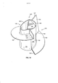
A Figura 10 é uma vista em perspectiva do isolador em espiral das Figuras 8 e 9.Figure 10 is a perspective view of the spiral insulator in Figures 8 and 9.
A modalidade da invenção descrita abaixo não pretende ser exaustiva ou limitar a invenção à estrutura e operação, exatas, reveladas. Mais propriamente, a modalidade descrita em detalhe abaixo foi escolhida e descrita para explicar os princípios da invenção e sua aplicação, operação e uso para melhor possibilitar que outros versados na técnica sigam os seus ensinamentos. Voltando-se agora para a Figura 1, é ilustrado o exterior de um tanque de refugo 10 tendo um separador de refugo de vértice 12 de acordo com a invenção. 0 separador de vórtice 12 inclui um alojamento 14 que é preferivelmente cilíndrico conforme mostrado e uma tampa de descarga 16 com um tubo de descarga 18 em cima do alojamento. A tampa de descarga pode ser presa de forma removível no topo do alojamento cilíndrico para permitir acesso ao interior do separador quando desejado e para permitir remoção e substituição de um cartucho de unidade de filtro em uma modalidade preferida da invenção. 0 tubo de descarga 18 será conectado conforme mostrado de forma diagramática a uma fonte de sucção compreendendo um gerador de vácuo 22 em baixas altitudes ou com a atmosfera externa em elevadas altitudes 24 para retirar o refugo a partir das privadas do avião ou outros receptáculos por intermédio do separador de vórtice. A comutação é obtida com uma válvula de retenção de desvio sensível à altitude 20. O separador de vórtice 12 tem um tubo de entrada 26 o qual em um avião funciona para transportar o fluxo de refugo a partir de uma privada de avião ou outro receptáculo para o separador. 0 tubo de entrada assim, por exemplo, recebe um fluxo de refugo compreendendo ar, papel higiênico, sólidos de refugo e outros materiais da privada do avião quando ela é descarregada. Esse fluxo, que é representado de forma diagramática pela seta WS1, é puxado para dentro do separador de vórtice 12 pela sucção provida ou pelo diferencial de pressão em elevadas altitudes ou pela operação de um gerador de vácuo em baixas altitudes aplicadas no tubo de descarga 18. Em altitudes abaixo de aproximadamente 4,88 kilometros (16.000 pés), o gerador de vácuo preferivelmente produzirá um vácuo de aproximadamente 3-9 polegadas de mercúrio. À medida que o avião sobe além de aproximadamente 4,88 kilometros (16.000 pés), o sistema comutará a partir do gerador de vácuo para o diferencial de cabine/atmosfera por intermédio da operação da válvula de retenção 20 para puxar o fluxo de refugo para dentro do separador. Quando o avião desce aquém de aproximadamente 4,88 kilometros (16.000 pés), o sistema comutará de volta para o gerador de vácuo. Finalmente, o tanque de refugo 10 inclui um tubo de drenagem 2 8 em sua parte inferior que será conectado a uma abertura de remoção de refugo no exterior do avião (não mostrado) através do qual o refugo coletado no tanque 10 será drenado durante manutenção do avião. Conforme pode ser visto na vista destacada da Figura 2 que ilustra a estrutura interna do separador de vórtice 12, o separador de vórtice 12 inclui um canal anular ótimo 30 em comunicação com o tubo de entrada 26 formado na superfície interna 31 da parede anular 32 do alojamento cilíndrico 14. Deve-se observar que a porção inferior 33 da parede 32 se estende para dentro do tanque de refugo 10 com uma borda anular externa 35 circundando a superfície externa 32A da parede se apoiando em uma borda correspondente 2 9 do tanque de modo que os dois podem ser presos juntos de forma removível (Figura 1).The embodiment of the invention described below is not intended to be exhaustive or to limit the invention to the exact structure and operation disclosed. More specifically, the modality described in detail below was chosen and described to explain the principles of the invention and its application, operation and use to better enable others versed in the technique to follow its teachings. Turning now to Figure 1, the exterior of a
Assim, o vácuo aplicado ao tubo de descarga 18 é transmitido através do separador de vórtice para puxar o fluxo WS1 para dentro do tubo de entrada 2 6 sob elevada velocidade. Esse fluxo de elevada velocidade é dirigido pelo tubo de entrada 26 para dentro do canal anular 30 que define um primeiro percurso de fluxo de vórtice VI. Quando o fluxo WS1 se desloca no percurso de fluxo VI um fluxo de ar mais leve WS2 migra para o centro do alojamento cilíndrico do separador quando a maior parte dos sólidos e líquidos mais pesados se desloca para o lado externo e caem do fluxo WS1 para o fundo do tanque de refugo 10. Em uma modalidade da invenção, o fluxo de ar WS2 pode ser retirado do separador através do tubo de descarga 18.Thus, the vacuum applied to the
É preferido, contudo, que uma unidade de filtro 27 seja provida tendo uma cavidade cônica truncada invertida 34 entre um cone interno invertido 36, encaixado dentro de um cone invertido externo 38. Assim, a superfície interna 3 7 do cone externo invertido 38 e a superfície externa 3 9 do cone interno invertido 36 definem a cavidade cônica invertida 34 que é geralmente centrada dentro do alojamento 14. Os cones encaixados 3 6 e 3 8 são montados abaixo da tampa de descarga 16, e são interligados por uma estrutura de suporte 40 na entrada para a cavidade cônica tendo pás 41 se estendendo radialmente no sentido para fora a partir de um cubo 43. As pás inclinadas em torno de seus eixos radiais para formar fendas angulares para induzir o movimento rotativo do fluxo de ar passando através das fendas para dentro da cavidade cônica 34 para o segundo percurso de vórtice. A estrutura de suporte 40 mantém o espaçamento entre os cones sem obstruir a passagem de material a partir da cavidade cônica no espaço entre as pás. Um funil 47 está localizado abaixo dos cones encaixados. 0 funil 47 posicionado abaixo dos cones encaixados tem um raio máximo menor que o raio mínimo do cone externo invertido 38 para divergir do fluxo de ar WS2 dentro da cavidade cônica 34. A superfície externa 51 do funil ajuda a desviar o fluxo de ar mais leve WS2 para dentro da cavidade cônica invertida 34.It is preferred, however, that a
Os cones truncados encaixados também definem uma abertura anular 45 (Figura 3) ao longo de sua borda inferior para dentro da qual é puxado o fluxo de ar WS2, e a partir da qual o material mais pesado cairá a partir da cavidade cônica 34 passando pelas pás 41 como será explicado em mais detalhe abaixo. Finalmente, a borda superior dos cones encaixados é geralmente fechada por um fecho superior anular 44 que tem uma ou mais aberturas ou cavidades 46 através das quais o fluxo de ar é transportado a partir da cavidade cônica. Segunda e terceira cavidades semelhantes estão localizadas separadas em 120°, mas estão ocultas da visão na Figura 2. O fluxo de ar WS2, portanto, é puxado através da cavidade cônica 34 pela força de sucção aplicada no tubo de descarga 18. Devido ao encaixe dos cones esse fluxo somente pode se deslocar entre as paredes dos cones. Como resultado da estrutura de esteio semelhante à ventoinha, opcional, o formato cônico da cavidade 34, e a elevada velocidade do fluxo se deslocando circularmente WS2, esse fluxo se deslocará através da cavidade 34 em um segundo percurso de fluxo de vórtice V2 o qual, como se pode ver na Figura 2, é isolado do percurso de fluxo de vórtice VI. 0 percurso de fluxo de vórtice V2 outra vez produz uma força centrifuga que faz com que os materiais mais pesados restantes (refugo particulado e líquido) se desloquem para o exterior onde ele cairá através da cavidade cônica 34 e da abertura anular 45 no fundo dos cones encaixados para dentro do tanque 10. Entretanto, o fluxo de ar mais leve restante WS3 passará para cima através das aberturas 46 no fecho superior 44 para ser puxado para baixo, para dentro de uma câmara cônica truncada invertida interna 50, definida pela superfície interna 48 do cone 36. Uma válvula de retenção de refugo 60 está localizada no fundo 54 da câmara 50. Essa válvula de retenção compreende uma membrana de borracha no formato de guarda- chuva invertido 52, sustentada abaixo da estrutura de esteio 56 por um elemento de travamento central projetado no sentido para cima 58 que é montado em um furo no centro da estrutura de esteio. A válvula de retenção permite que os sólidos e os líquidos caiam a partir da câmara cônica truncada 50 para o funil 4 7 e para fora da abertura de funil inferior 49 para o tanque de refugo 10, mas não permite que o ar contaminado a partir de baixo da válvula de retenção entre na câmara, conforme explicado abaixo. Conforme ilustrado diagramaticamente na Figura 3, a câmara 50 também contém um primeiro material de filtro 62 que ajuda a coalescer a umidade restante quando o fluxo se desloca através da câmara cônica truncada 50 para sair de uma porção adicional do fluxo de refugo WS3 com no máximo quantidades mínimas de umidade quando ele sai da câmara 50. O fluxo WS3 a seguir entra em um elemento de descarga 63 que tem uma prateleira anular 64 que se apóia no topo do cone 36 e uma porção tubular 66, centrada acima da câmara 50, com a porção tubular 66 se estendendo parcialmente para dentro da câmara e o flange anular sustentando o elemento de descarga através do topo dos cones encaixados. A prateleira 64 se apóia abaixo da tampa de descarga 16 do separador de vórtice. Preferivelmente, um material de filtro desembaçador 72 é disposto através da abertura superior da porção tubular 66 para reter a umidade e ajudar a remover a umidade arrastada na névoa que se desloca além da malha através da tampa 16 e para fora do tubo de descarga 18. Os dois materiais de filtro 62 e 72 preferivelmente estão na forma de uma malha trançada densa de metal, náilon ou propileno. Assim, o material de filtro 72 é posicionado para remover a maior parte, senão toda a umidade restante no fluxo WS3, de modo que o fluxo de ar se deslocando através do tubo de descarga 18 para a atmosfera externa estará livre de umidade. O dispositivo operará quando o ciclo de descarga da privada do avião é iniciado. Quando isso acontece, o fluxo de refugo WS1 será puxado a partir da privada através do tubo de entrada 2 6 para dentro do canal anular 3 0 e primeiro percurso de fluxo de vórtice VI no qual a força centrífuga resultante faz com que os componentes mais pesados da mistura de refugo se desloque para o exterior e caia dentro do tanque de refugo 10, conforme discutido anteriormente.The fitted truncated cones also define an annular opening 45 (Figure 3) along its lower edge into which the WS2 airflow is drawn, and from which the heavier material will fall from the
Entretanto, um fluxo compreendendo o vórtice em movimento rápido restante WS2 entra na cavidade cônica truncada invertida 34 através das fendas angulares entre as pás 41, e os sólidos restantes e a água são adicionalmente separados pela força centrífuga produzida em um segundo percurso de fluxo de vórtice V2 fazendo com que sólidos adicionais e água caiam dentro do tanque de refugo 10, deixando o fluxo de refugo restante WS3 como um fluxo de ar substancialmente livre de sólidos e com um nível de líquido substancialmente reduzido. 0 WS3 é então puxado a partir do centro do alojamento cilíndrico do separador para dentro da cavidade cônica 34 através das aberturas 46 ao longo do canal anular 55 do fecho 44 e para dentro da câmara cônica invertida onde ele passa para cima através do primeiro material de filtro 62 que ajuda a coalescer o líquido arrastado restante no fluxo WS3 de modo que ele se acumula e cai para o fundo da câmara cônica invertida. Como resultado, quando o vácuo no sistema não mais é aplicado, a válvula de retenção 6 0 abrirá sob o peso do material acumulado no fundo da câmara 6 0 de modo que esse material de refugo pode se deslocar além da válvula de retenção para dentro do funil 47 a partir do qual ela cairá através da abertura inferior do funil 49 para o fundo do tanque 10 se juntando ao refugo anteriormente separado.However, a flow comprising the remaining fast-moving vortex WS2 enters the inverted truncated
Deve-se observar que os vórtices VI e V2 não se intersectam. Isso é uma característica importante da invenção uma vez que a mistura dos fluxos de refugo de alta velocidade que se cruzam movendo através dos vórtices faria com que umidade e sólidos particulados adicionais fossem formados reduzindo significativamente a eficácia do separador. O fluxo restante WS3 passa a partir da porção tubular da câmara de descarga 66 do elemento de descarga 63 através do filtro desembaçador 72 onde ele passa através da tampa de descarga 16 para dentro do tubo de descarga 18 ou para o gerador de vácuo ou para a atmosfera se o avião estiver operando em elevada altitude. Tipicamente, o processo acima, a partir da aplicação do vácuo através da conclusão do processo de separação levará aproximadamente de 1 a 4 segundos.It should be noted that vortices VI and V2 do not intersect. This is an important feature of the invention since the mixture of the high-speed waste streams that intersect moving through the vortexes would cause additional particulate solids and moisture to be formed significantly reducing the efficiency of the separator. The remaining flow WS3 passes from the tubular portion of the
Em uma modalidade alternativa da invenção, a unidade de filtro 27 pode estar na forma de um cartucho de unidade de filtro removível 150, que é ilustrado nas Figuras 4 e 5. Esse cartucho é projetado para ser acessado mediante remoção da tampa 16 (Figura 6). Assim, periodicamente e com a tampa removida, o cartucho pode ser deslizado para fora do separador 12 onde ele se apóia sobre uma borda 162 no topo do separador (Figura 8) e substituído por um novo cartucho de unidade de filtro.In an alternative embodiment of the invention, the
O cartucho 150 inclui desse modo, um cone invertido interno 36A encaixado dentro de um cone invertido externo 38A com a superfície interna do cone invertido externo e a superfície externa do cone invertido interno definindo uma cavidade cônica invertida 34A. Preferivelmente, um filtro cônico 154 feito de material de filtro desembaçador se apóia dentro do cone 36A.The
Uma prateleira anular 156 está localizada no topo do cone 36A. Abaixo da prateleira está uma série de aberturas 158 providas por intermédio de cavidades circulares radialmente divergentes no sentido para fora 160 que circundam o cone. Nessa modalidade, duas das tais cavidades são visíveis, mas três cavidades igualmente separadas em 120° estão presentes. As bordas inferiores das cavidades se projetam no sentido para fora para formar uma prateleira inferior 162. Um flange superior 170 é geralmente perpendicular ao eixo longitudinal do cone e define o topo do cone externo assim como a superfície superior das cavidades. 0 cone 36A também tem uma estrutura de suporte de esteio 56A em sua entrada inferior.An
Uma válvula de retenção de refugo 60 está localizada abaixo da estrutura de suporte de esteio 56A do cone externo. Como nas modalidades anteriores, essa válvula de retenção compreende uma membrana de borracha no formato de guarda-chuva invertido sustentada abaixo da estrutura de esteio 56A por um membro de travamento projetado no sentido para cima, central 58 que é montado no centro da estrutura de suporte de esteio. O cartucho 150 inclui também um elemento superior 168 tendo o flange superior 170 que se apóia na prateleira 156 do cartucho de filtro. 0 elemento superior 168 inclui uma porção tubular orientada no sentido para baixo 172 que ajuda a posicionar o elemento superior e manter o elemento de filtro tubular 176 (descrito abaixo) no lugar no cartucho completamente montado. 0 elemento superior inclui também uma depressão anular orientada no sentido para baixo 174 correspondendo geralmente em diâmetro ao diâmetro interno do cone 36A para ajudar a manter o elemento superior dentro do cone interno 36A. O primeiro elemento de filtro tubular 176 feito de material de filtro desembaçador é encaixado por pressão na porção tubular 162 do elemento superior 168. O elemento superior 168 inclui também uma cavidade anular estendida no sentido para acima 180 estabelecida por uma parede vertical circular 184. Três filtros desembaçadores circulares 186, 188, e 190 são posicionados na cavidade 180. Evidentemente, qualquer número desejado de tais filtros desembaçador pode ser usado. Os filtros circulares desembaçador são travados no lugar por intermédio de um anel de plástico 182 que pode ser colado ou empilhado a calor no lugar contra a parede 184.A
Voltando-se a seguir para a Figura 6, o separador de vórtice da invenção é mostrado com o cartucho 150 no lugar no cone externo 3 8A que sustenta um funil 4 7 como na modalidade das Figuras 1-3. Essa figura também mostra um prendedor 192 para facilitar a remoção da tampa 16 para substituir o cartucho e um anel-0 194 para manter a vedação entre a tampa e o topo do separador de vórtice quando a tampa é travada no lugar. Esta figura também mostra um grampo 102 para facilitar a fixação removível junto com a borda anular externa do separador de vórtice com uma borda anular externa correspondente do tanque de refugo.Turning now to Figure 6, the vortex separator of the invention is shown with the
A Figura 7 ilustra uma modalidade preferida da invenção na qual o tubo de entrada 2 6A está em um ângulo "A" com relação ao plano horizontal. 0 ângulo "A" deve ser de pelo menos aproximadamente 10° e pode ser maior, desde que folga suficiente esteja disponível. A inclinação do tubo de entrada acrescenta um auxílio gravitacional para o refugo se deslocando para dentro do separador de vórtice para entregar o refugo num fluxo de ar em espiral no sentido para baixo do separador de vórtice.Figure 7 illustrates a preferred embodiment of the invention in which the
Preferivelmente, o separador de vórtice inclui também um isolador em espiral 120 o qual é mostrado isolado (e invertido para fins de ilustração) na Figura 10, e mostrado no lugar no separador de vórtice nas vistas em elevação e inferior das Figuras 8 e 10. 0 isolador em espiral 120 compreende assim um elemento central geralmente cilíndrico 122 que é ligado na superfície externa 110 do cone externo 3 8A. O isolador em espiral inclui uma primeira pá helicoidal 126 que se projeta para longe da superfície externa 128 do elemento cilíndrico 122 até a superfície interna 31 do separador e um primeiro defletor lateral orientado geralmente no sentido para baixo 130 (se projetando no sentido para cima na Figura 10 para fins de ilustração) no ponto final inferior 132 da pá. 0 defletor 130 é preferivelmente inclinado com relação à vertical definida pelo eixo central do isolador em espiral. Por exemplo, a pá pode estar inclinada em aproximadamente 10° com relação ao eixo central. O isolador em espiral inclui também uma segunda pá helicoidal 134 também se projetando para longe da superfície externa 128 até a superfície interna 31 do separador. A pá helicoidal 134 tem um segundo defletor lateral direcionado geralmente no sentido para baixo 136 no ponto final inferior 138 dessa pá. As bordas opostas 140 e 142 das pás que são diametralmente opostas em lados opostos do elemento cilíndrico 122 são abertas de modo a não impedir o material de chegada ou o fluxo de ar. Além disso, preferivelmente as pás 126 e 134 em conjunto se estendem em 360° em torno do elemento cilíndrico 122. A borda inferior 147 do defletor 130 preferivelmente será espaçada da borda inferior 149 da abertura de saída 148 para garantir folga do fluxo de ar na parte inferior do isolador em espiral. Esse espaçamento deve ser de pelo menos aproximadamente meia polegada (1,27 cm).Preferably, the vortex separator also includes a
Finalmente, um defletor inferior 144 está localizado na abertura de saída 146 do membro central 122 do separador helicoidal. Esse defletor é inclinado em pelo menos 10° com relação ao eixo longitudinal do membro central para ajudar a impedir que o refugo entre na saída 148 da abertura de saída. Se o refugo não entrar na abertura durante a operação de descarga, ele será capaz de drenar para fora entre as descargas devido a essa estrutura. O isolador em espiral 120 ajuda a garantir que o refugo no fluxo de refugo WS2 e o percurso de fluxo de vórtice V2 continue seu movimento em espiral no sentido para baixo sem se tornar arrastado no fluxo de ar para dentro da cavidade cônica 34A entre os cones encaixados eliminando assim ou minimizando o acúmulo de refugo sobre as superfícies cônicas 37 e 39. Desse modo, preferivelmente, a superfície superior 151 da pá de isolador 126 será posicionada exatamente abaixo do ponto de entrada através do tubo de entrada 2 6A que é rotulado "153" na Figura 8. Os defletores laterais 130 e 136 por sua vez permitem que o refugo saia da espiral. 0 defletor inferior 144 limita a área para escapamento do ar do tanque do sistema. As espiras e os defletores laterais e inferiores desse modo isolam a descarga de ar a partir do tanque do refugo que está caindo dentro do tanque. O objetivo da presente invenção é o de puxar o fluxo de refugo contendo refugo líquido e sólido, remover o refugo líquido e sólido do fluxo de ar e produzir um fluxo de ar de descarga livre de líquido. A estrutura da presente invenção alcança esse objetivo de uma forma eficiente, segura e efetiva.Finally, a
Todas as referências, incluindo publicações, pedidos de patente, e patentes, aqui citadas e aqui incorporadas mediante referência na mesma amplitude como se cada referência fosse individualmente especificamente indicada para ser incorporada, mediante referência, e onde apresentada aqui em sua totalidade. O uso dos termos "um" e "uma" e "o" e referentes similares no contexto da descrição da invenção (especialmente no contexto das reivindicações a seguir) devem ser considerados como abrangendo o singular e o plural, a menos que aqui de outro modo indicado ou claramente contradito pelo contexto. A citação aqui de faixas de valores pretende apenas servir como um método abreviado de se referir individualmente a cada valor separado compreendido na faixa, a menos que de outro modo aqui indicado, e cada valor separado é incorporado no relatório descritivo como se fosse aqui individualmente citado. Todos os métodos aqui descritos podem ser realizados em qualquer ordem adequada a menos que de outro modo aqui indicado ou de outro modo claramente contradito pelo contexto. 0 uso de qualquer um ou de todos os exemplos, ou linguagem exemplar (por exemplo, "tal como") aqui provida, pretende apenas iluminar melhor a invenção e não apresenta uma limitação ao escopo da invenção a menos que de outro modo reivindicado. Nenhuma linguagem no relatório descritivo deve ser considerada como indicando qualquer elemento não reivindicado como essencial para a prática da invenção.All references, including publications, patent applications, and patents, cited and incorporated herein by reference in the same amplitude as if each reference were individually specifically indicated to be incorporated, by reference, and where presented here in their entirety. The use of the terms "one" and "one" and "o" and similar referents in the context of the description of the invention (especially in the context of the following claims) should be considered as encompassing the singular and the plural, unless here of another indicated or clearly contradicted by the context. The quote here of ranges of values is only intended to serve as an abbreviated method of referring individually to each separate value included in the range, unless otherwise indicated here, and each separate value is incorporated into the specification as if it were individually quoted here . All methods described herein can be performed in any suitable order unless otherwise indicated herein or otherwise clearly contradicted by the context. The use of any or all of the examples, or exemplary language (for example, "as is") provided herein, is only intended to further illuminate the invention and does not present a limitation on the scope of the invention unless otherwise claimed. No language in the specification should be considered to indicate any element not claimed as essential to the practice of the invention.
Modalidades preferidas dessa invenção são descritas 5 aqui, incluindo o melhor modo conhecido pelos inventores para a realização da invenção. Deve-se entender que as modalidades ilustradas são apenas exemplares, e não devem ser consideradas como limitando o escopo da invenção.Preferred embodiments of this invention are described here, including the best way known to the inventors for carrying out the invention. It should be understood that the illustrated modalities are only exemplary, and should not be considered as limiting the scope of the invention.
Claims (17)
Applications Claiming Priority (3)
| Application Number | Priority Date | Filing Date | Title |
|---|---|---|---|
| US12/245,541 | 2008-10-03 | ||
| US12/245,541 US7998250B2 (en) | 2008-10-03 | 2008-10-03 | Multiple vortex waste separator apparatus |
| PCT/US2009/059358 WO2010040039A1 (en) | 2008-10-03 | 2009-10-02 | Vortex waste separator apparatus |
Publications (2)
| Publication Number | Publication Date |
|---|---|
| BRPI0919836A2 BRPI0919836A2 (en) | 2015-12-15 |
| BRPI0919836B1 true BRPI0919836B1 (en) | 2020-10-06 |
Family
ID=42073905
Family Applications (1)
| Application Number | Title | Priority Date | Filing Date |
|---|---|---|---|
| BRPI0919836-9A BRPI0919836B1 (en) | 2008-10-03 | 2009-10-02 | MULTIPLE VORTEX SEPARATOR AND METHOD OF REMOVING AN AIR FLOW |
Country Status (8)
| Country | Link |
|---|---|
| US (1) | US7998250B2 (en) |
| EP (2) | EP2767345B1 (en) |
| JP (1) | JP4969703B2 (en) |
| CN (2) | CN102170947B (en) |
| BR (1) | BRPI0919836B1 (en) |
| CA (1) | CA2736436C (en) |
| RU (1) | RU2452552C1 (en) |
| WO (1) | WO2010040039A1 (en) |
Families Citing this family (37)
| Publication number | Priority date | Publication date | Assignee | Title |
|---|---|---|---|---|
| US7998250B2 (en) * | 2008-10-03 | 2011-08-16 | B/E Aerospace, Inc. | Multiple vortex waste separator apparatus |
| DE102008058750B4 (en) * | 2008-11-24 | 2019-04-11 | Airbus Operations Gmbh | cyclone |
| JP2010269210A (en) * | 2009-05-19 | 2010-12-02 | Tosei Kk | Cyclone dust collector |
| CN101890261B (en) * | 2010-07-22 | 2011-12-28 | 中科华核电技术研究院有限公司 | Containment sump filter and filter cartridge structure thereof |
| US8419833B2 (en) * | 2011-02-03 | 2013-04-16 | Haven Technology | Apparatus and method for gas-liquid separation |
| US8771393B1 (en) | 2011-08-29 | 2014-07-08 | Exelis, Inc. | Integrated polar cap for a vacuum waste tank system |
| US8864863B1 (en) | 2011-08-29 | 2014-10-21 | Exelis Inc. | Three-stage separator for a vacuum waste tank system |
| GB201208169D0 (en) * | 2012-05-10 | 2012-06-20 | Norgren Ltd C A | Gas/liquid separator |
| CN104508190B (en) | 2012-05-25 | 2017-12-15 | 索尔伏打电流公司 | Concentric flow reactor |
| CN102772955B (en) * | 2012-08-27 | 2015-08-19 | 北京雪迪龙科技股份有限公司 | A kind of steam trap |
| CN103357233B (en) * | 2013-07-04 | 2015-10-07 | 上海大学 | Three-phase oil mist fluid acquisition separation method and device |
| JP2015074523A (en) * | 2013-10-08 | 2015-04-20 | 東洋ハイテック株式会社 | Pneumatic transportation device |
| DE202013011431U1 (en) * | 2013-12-20 | 2015-03-23 | Evac Gmbh | Vacuum toilet with centrifugal separator |
| CN104399341B (en) * | 2014-10-17 | 2016-04-27 | 河海大学 | A kind of oil mist treatment device of multistage cold former |
| JP6624819B2 (en) * | 2015-06-18 | 2019-12-25 | ヤマシンフィルタ株式会社 | Return filter |
| CN105498987B (en) * | 2015-12-01 | 2017-04-12 | 东北石油大学 | Three-phase separation cyclone separator |
| CN107138291B (en) * | 2016-08-26 | 2020-05-08 | 汪开泉 | Continuous automatic separation type spiral filtering centrifuge |
| JP2018198902A (en) * | 2017-05-30 | 2018-12-20 | 三菱電機株式会社 | Vacuum cleaner with cyclone separator |
| US10724437B2 (en) | 2017-06-28 | 2020-07-28 | General Electric Company | Systems and methods for particle separator in a gas turbine engine |
| KR102482234B1 (en) * | 2017-09-19 | 2022-12-28 | 삼성전자주식회사 | Filter unit and air cleaner having the same |
| CN107999288B (en) * | 2018-02-01 | 2020-08-11 | 中国科学院青岛生物能源与过程研究所 | Novel outlet structure's hydrocyclone |
| US10953412B2 (en) * | 2018-07-23 | 2021-03-23 | Contech Engineered Solutions LLC | Hydrodynamic separator |
| CN108636623A (en) * | 2018-07-24 | 2018-10-12 | 山东泰溥建材科技有限公司 | Cyclone cylinder efficient cyclone |
| US11504484B2 (en) * | 2018-09-19 | 2022-11-22 | Arthur Formanek | Inline microgravity air trap device and an intravenous assembly incorporating an inline microgravity air trap device |
| US10737018B2 (en) * | 2018-09-19 | 2020-08-11 | Arthur Formanek | Inline microgravity air trap device and an intravenous assembly incorporating an inline microgravity air trap device |
| US20200179856A1 (en) * | 2018-12-10 | 2020-06-11 | Bendix Commercial Vehicle Systems Llc | Effluent Processing Apparatus and Method for a Vehicle Air Brake Charging System |
| US10478753B1 (en) | 2018-12-20 | 2019-11-19 | CH International Equipment Ltd. | Apparatus and method for treatment of hydraulic fracturing fluid during hydraulic fracturing |
| CA3125549A1 (en) | 2018-12-20 | 2020-06-25 | Haven Technology Solutions Llc | Apparatus and method for gas-liquid separation of multi-phase fluid |
| CN109675392A (en) * | 2018-12-26 | 2019-04-26 | 深圳市贝克科技有限公司 | A kind of oil-free unit and its application |
| US11123677B2 (en) | 2019-02-20 | 2021-09-21 | B/E Aerospace, Inc. | Integrated vortex separator |
| US11351492B2 (en) | 2019-02-20 | 2022-06-07 | B/E Aerospace, Inc. | Inline vortex demister |
| US11001382B2 (en) | 2019-02-20 | 2021-05-11 | B/E Aerospace, Inc. | Bypass flow regulator |
| NL2023332B1 (en) * | 2019-06-17 | 2021-01-25 | Mst Nl B V | Filter device for removing particles from a fluid |
| CN112999701B (en) * | 2019-12-20 | 2023-08-11 | 台湾积体电路制造股份有限公司 | Apparatus for removing bubbles from viscous fluids |
| KR102203139B1 (en) * | 2020-03-19 | 2021-01-21 | 남숭호 | Apparatus for purifying exhaust gas using rotational force |
| CN112973359B (en) * | 2021-03-18 | 2022-03-29 | 中国石油大学(北京) | Sectional liquid discharge type combined coalescent filter element |
| US11674396B2 (en) | 2021-07-30 | 2023-06-13 | General Electric Company | Cooling air delivery assembly |
Family Cites Families (50)
| Publication number | Priority date | Publication date | Assignee | Title |
|---|---|---|---|---|
| US2187646A (en) * | 1935-08-16 | 1940-01-16 | Bbc Brown Boveri & Cie | Separator |
| US2708033A (en) | 1951-06-12 | 1955-05-10 | Prater Pulverizer Company | Fractionator |
| DE1069116B (en) * | 1952-09-24 | 1959-11-19 | Nichols Engineering S. Research Corporation, New- York, N. Y. (V.St.A.) | Method and device for separating fibrous suspensions containing solids on a hydrocyclone |
| US3616617A (en) | 1969-01-13 | 1971-11-02 | United Aircraft Prod | Liquid separator |
| US3902876A (en) | 1972-07-21 | 1975-09-02 | Gen Electric | Gas-liquid vortex separator |
| JPS52149666A (en) * | 1976-06-07 | 1977-12-12 | Kobe Steel Ltd | Cyclone classifier |
| JPS592540B2 (en) * | 1976-10-28 | 1984-01-19 | 新明和工業株式会社 | Cyclone |
| US4200415A (en) * | 1978-08-03 | 1980-04-29 | Conair, Inc. | Material loading device |
| DE2918765A1 (en) | 1979-05-10 | 1980-11-13 | Kloeckner Humboldt Deutz Ag | Centrifugal dust separator system with several stages |
| US4385912A (en) * | 1981-09-30 | 1983-05-31 | The Boeing Company | Apparatus for extracting liquid and foam from gas |
| US4469497A (en) | 1982-02-04 | 1984-09-04 | Linhardt & Associates, Inc. | Axisymmetrical separator for separating particulate matter from a fluid carrying medium |
| US4566883A (en) * | 1983-04-08 | 1986-01-28 | Shell Oil Company | Apparatus for gas/liquid separation |
| JPS6128473A (en) * | 1984-07-20 | 1986-02-08 | Giken Eng:Kk | Double liquid cyclone |
| US4612120A (en) | 1984-11-01 | 1986-09-16 | United States Steel Corporation | Axisymmetrical separator for separating solids and gas from a fluid medium |
| CA1286345C (en) * | 1986-06-19 | 1991-07-16 | Llewellyn Ernest Depew | Feed and separation device |
| US4968325A (en) | 1987-08-24 | 1990-11-06 | Centre Quebecois De Valorisation De La Biomasse | Fluidized bed gasifier |
| JPH01148266A (en) * | 1987-12-04 | 1989-06-09 | Terumo Corp | Blood filter |
| US5002592A (en) * | 1988-02-26 | 1991-03-26 | Oy Wartsila Ab | Waste tank for a vacuum sewage system |
| JP2609168B2 (en) * | 1989-12-16 | 1997-05-14 | 秩父小野田株式会社 | Rectifying member and cyclone |
| FR2665468B1 (en) * | 1990-08-03 | 1992-11-27 | Lebozec & Gautier | SANITARY INSTALLATION WITH LOW PRESSURE PROVIDED WITH A GAS FLUID PURIFIER. |
| US5026407A (en) * | 1990-09-06 | 1991-06-25 | The Boeing Company | External separator for vacuum waste system |
| US5538546A (en) * | 1992-10-27 | 1996-07-23 | E. I. Du Pont De Nemours And Company | Waste tank for vacuum sewage system |
| US5447630A (en) * | 1993-04-28 | 1995-09-05 | Rummler; John M. | Materials treatment process and apparatus |
| US5510019A (en) * | 1993-07-30 | 1996-04-23 | Mitsubishi Oil Co., Ltd. | Bubble separating apparatus |
| FI93667C (en) * | 1993-09-21 | 1995-05-10 | Evac Ab | Vacuum Drainage Device |
| RU2091123C1 (en) * | 1994-07-18 | 1997-09-27 | Центральный научно-исследовательский институт "Гидроприбор" | Filter for cleaning liquids |
| JPH0893439A (en) * | 1994-09-22 | 1996-04-09 | Tokai Rubber Ind Ltd | Oil mist particle separation growing device and oil mist separation recovering device using it |
| AU5194096A (en) * | 1995-04-27 | 1996-11-07 | William C. Rose | Liquid separator and polishing filter thereof |
| US6019825A (en) * | 1995-10-18 | 2000-02-01 | Gnesys, Inc. | Hydrocyclone gas separator |
| US6206943B1 (en) * | 1997-09-10 | 2001-03-27 | Edo Fiber Science | Separator system for aircraft waste system |
| JPH11179240A (en) * | 1997-12-25 | 1999-07-06 | Sharp Corp | Rotational gas-liquid separator and gas-liquid separation system |
| WO1999033570A1 (en) | 1997-12-25 | 1999-07-08 | Sharp Kabushiki Kaisha | Swing type gas-liquid separator and gas-liquid separation system |
| DE19811090A1 (en) * | 1998-03-13 | 1999-09-16 | Georg Klas | Cyclone separator for effluent household gray water |
| GB9926009D0 (en) * | 1999-11-04 | 2000-01-12 | Vax Ltd | Dust filter |
| GB2362341B (en) | 2000-05-16 | 2002-12-04 | Samsung Kwangju Electronics Co | Upright-type vacuum cleaner |
| GB2363744B (en) | 2000-06-24 | 2002-11-13 | Samsung Kwangju Electronics Co | Upright type vacuum cleaner having a cyclone-type dust collector |
| US20020145080A1 (en) | 2001-04-07 | 2002-10-10 | Frank Renken | Suction conveying system, such as a vacuum wastewater system for an aircraft |
| US7776213B2 (en) | 2001-06-12 | 2010-08-17 | Hydrotreat, Inc. | Apparatus for enhancing venturi suction in eductor mixers |
| AUPR912001A0 (en) | 2001-11-27 | 2001-12-20 | Rmg Services Pty. Ltd. | Advanced liquid vortex separation system |
| NO321638B1 (en) * | 2003-05-08 | 2006-06-12 | Aibel As | Inlet device and a method for controlling the introduction of a fluid into a separator |
| US7413669B2 (en) * | 2004-04-06 | 2008-08-19 | Intevep, S.A. | Separator for liquids and/or multiphase fluids |
| JP3976750B2 (en) * | 2004-06-04 | 2007-09-19 | 三立機器株式会社 | Vacuum cleaner |
| WO2006026414A2 (en) * | 2004-08-26 | 2006-03-09 | Euro-Pro Operating, Llc | Cyclonic separation device for a vacuum cleaner |
| JP2006061897A (en) * | 2004-08-27 | 2006-03-09 | Masuki Takasu | Two-stage separation apparatus |
| US7559965B2 (en) * | 2005-01-25 | 2009-07-14 | Samsung Gwangju Electronics Co., Ltd. | Cyclonic separating apparatus for vacuum cleaner which is capable of separately collecting water from dust |
| DE102006016507B4 (en) * | 2006-04-07 | 2010-07-29 | Airbus Deutschland Gmbh | Drainage device for a sanitary basin in an aircraft |
| KR20070101056A (en) * | 2006-04-10 | 2007-10-16 | 삼성전자주식회사 | A cyclone and a cyclone air purifier |
| RU2319533C1 (en) * | 2006-11-17 | 2008-03-20 | Шамиль Халикович Ахметзянов | Method of separation of gas-liquid mediums |
| CN200987936Y (en) * | 2006-12-29 | 2007-12-12 | 中国石油大学(华东) | Novel cyclone filter combined separator |
| US7998250B2 (en) * | 2008-10-03 | 2011-08-16 | B/E Aerospace, Inc. | Multiple vortex waste separator apparatus |
-
2008
- 2008-10-03 US US12/245,541 patent/US7998250B2/en active Active
-
2009
- 2009-10-02 EP EP13197541.9A patent/EP2767345B1/en active Active
- 2009-10-02 RU RU2011117276/05A patent/RU2452552C1/en active
- 2009-10-02 CN CN200980138862.8A patent/CN102170947B/en active Active
- 2009-10-02 CN CN201410048381.0A patent/CN103934122B/en active Active
- 2009-10-02 WO PCT/US2009/059358 patent/WO2010040039A1/en active Application Filing
- 2009-10-02 EP EP09818557.2A patent/EP2358456B1/en active Active
- 2009-10-02 BR BRPI0919836-9A patent/BRPI0919836B1/en active IP Right Grant
- 2009-10-02 CA CA2736436A patent/CA2736436C/en active Active
- 2009-10-02 JP JP2011530264A patent/JP4969703B2/en active Active
Also Published As
| Publication number | Publication date |
|---|---|
| JP4969703B2 (en) | 2012-07-04 |
| EP2358456B1 (en) | 2014-02-19 |
| RU2452552C1 (en) | 2012-06-10 |
| EP2358456A4 (en) | 2012-05-23 |
| CA2736436A1 (en) | 2010-04-08 |
| CN103934122A (en) | 2014-07-23 |
| CA2736436C (en) | 2012-08-07 |
| CN103934122B (en) | 2016-08-17 |
| BRPI0919836A2 (en) | 2015-12-15 |
| EP2767345B1 (en) | 2018-12-05 |
| CN102170947B (en) | 2014-03-12 |
| US7998250B2 (en) | 2011-08-16 |
| JP2012504495A (en) | 2012-02-23 |
| EP2358456A1 (en) | 2011-08-24 |
| EP2767345A2 (en) | 2014-08-20 |
| WO2010040039A1 (en) | 2010-04-08 |
| CN102170947A (en) | 2011-08-31 |
| EP2767345A3 (en) | 2015-03-11 |
| US20100084352A1 (en) | 2010-04-08 |
Similar Documents
| Publication | Publication Date | Title |
|---|---|---|
| BRPI0919836B1 (en) | MULTIPLE VORTEX SEPARATOR AND METHOD OF REMOVING AN AIR FLOW | |
| US7998251B2 (en) | Vortex waste separator apparatus | |
| ES2253991B1 (en) | "CYCLONE DUST SEPARATOR APPARATUS FOR VACUUM CLEANER AND VACUUM CLEANER." | |
| KR100767122B1 (en) | Cyclone dust collecting apparatus for vacuum cleaner | |
| US7025890B2 (en) | Dual stage centrifugal liquid-solids separator | |
| ES2356570T3 (en) | CYCLONE SEPARATION APPARATUS. | |
| CA2687349C (en) | Induced vortex particle separator | |
| BRPI0609243A2 (en) | separator for separating a flow into a first fluid, a second fluid denser than the first fluid, and solids as well as a system including the separator | |
| CN101730495A (en) | Cyclonic utility vacuum | |
| CN111050921B (en) | Cyclone separator | |
| JP2012520170A (en) | Cyclone separator | |
| US4385912A (en) | Apparatus for extracting liquid and foam from gas | |
| JP2021501861A (en) | How to use the filtration device and brake dust to separate and collect it | |
| US20130312609A1 (en) | Apparatus and methods for filtration of solid particles and separation of liquid droplets and liquid aerosols from a gas stream | |
| EP3698879B1 (en) | Integrated vortex separator | |
| US5234483A (en) | Negative pressure sanitary installation equipped with a purifier of gaseous fluids | |
| ES2702628T3 (en) | Separation system for wet vacuum cleaners | |
| US6206943B1 (en) | Separator system for aircraft waste system | |
| KR20180090281A (en) | Cyclone system | |
| US8864863B1 (en) | Three-stage separator for a vacuum waste tank system | |
| KR20050056817A (en) | Dust removing apparatus for vacuum cleaner | |
| CN208642995U (en) | A kind of cyclone separator for long distance gas pipeline | |
| US11872879B2 (en) | Fuel pick-up device | |
| KR101872512B1 (en) | Cyclone separating apparatus | |
| RU2150986C1 (en) | Oil and water separator |
Legal Events
| Date | Code | Title | Description |
|---|---|---|---|
| B06F | Objections, documents and/or translations needed after an examination request according [chapter 6.6 patent gazette] | ||
| B06U | Preliminary requirement: requests with searches performed by other patent offices: procedure suspended [chapter 6.21 patent gazette] | ||
| B06G | Technical and formal requirements: other requirements [chapter 6.7 patent gazette] | ||
| B07A | Application suspended after technical examination (opinion) [chapter 7.1 patent gazette] | ||
| B09A | Decision: intention to grant [chapter 9.1 patent gazette] | ||
| B16A | Patent or certificate of addition of invention granted [chapter 16.1 patent gazette] |
Free format text: PRAZO DE VALIDADE: 10 (DEZ) ANOS CONTADOS A PARTIR DE 06/10/2020, OBSERVADAS AS CONDICOES LEGAIS. |