JP2018198902A - Vacuum cleaner with cyclone separator - Google Patents

Vacuum cleaner with cyclone separator Download PDF

Info

Publication number
JP2018198902A
JP2018198902A JP2017106135A JP2017106135A JP2018198902A JP 2018198902 A JP2018198902 A JP 2018198902A JP 2017106135 A JP2017106135 A JP 2017106135A JP 2017106135 A JP2017106135 A JP 2017106135A JP 2018198902 A JP2018198902 A JP 2018198902A
Authority
JP
Japan
Prior art keywords
swirl chamber
dust
vacuum cleaner
port
inflow
Prior art date
Legal status (The legal status is an assumption and is not a legal conclusion. Google has not performed a legal analysis and makes no representation as to the accuracy of the status listed.)
Pending
Application number
JP2017106135A
Other languages
Japanese (ja)
Inventor
茉莉花 服巻
Marika Fukumaki
茉莉花 服巻
浩志郎 ▲高▼野
浩志郎 ▲高▼野
Koshiro Takano
近藤 大介
Daisuke Kondo
大介 近藤
Current Assignee (The listed assignees may be inaccurate. Google has not performed a legal analysis and makes no representation or warranty as to the accuracy of the list.)
Mitsubishi Electric Home Appliance Co Ltd
Mitsubishi Electric Corp
Original Assignee
Mitsubishi Electric Home Appliance Co Ltd
Mitsubishi Electric Corp
Priority date (The priority date is an assumption and is not a legal conclusion. Google has not performed a legal analysis and makes no representation as to the accuracy of the date listed.)
Filing date
Publication date
Application filed by Mitsubishi Electric Home Appliance Co Ltd, Mitsubishi Electric Corp filed Critical Mitsubishi Electric Home Appliance Co Ltd
Priority to JP2017106135A priority Critical patent/JP2018198902A/en
Publication of JP2018198902A publication Critical patent/JP2018198902A/en
Pending legal-status Critical Current

Links

Images

Abstract

To provide a vacuum cleaner in which the routing performance of a main body can be secured without reducing suction power.SOLUTION: A vacuum cleaner 1 includes a hose 5 coming in communication with a cyclone separator 6 through a connection port 10 formed in a main body 7 equipped with the cyclone separator 6 and making dust-containing air circulate inside. The cyclone separator 6 includes: a cylindrical swirling chamber 13 formed of an inflow port 18 and an exhaust port 19, swirling the dust-containing air and separating it into air and dust; an inflow pipe 15 for making the dust-containing air flow into the swirling chamber 13 through the inflow port 18; and an exhaust pipe 16 for exhausting the air from the inside of the swirling chamber 13 through the exhaust port 19. The connection port 10 is formed downward more than the center of the height direction of the main body 7. An opening surface of the connection port 10 is opposed to the opening surface of the upstream end of the inflow pipe 15, and is arranged adjacently. The inflow port 18 is arranged in the axial lower part of the swirling chamber 13 more than the exhaust port 19. The inflow pipe 15 is slanted to the axial direction of the swirling chamber 13.SELECTED DRAWING: Figure 2

Description

本発明は、サイクロン分離装置を備えた電気掃除機に関する。   The present invention relates to a vacuum cleaner provided with a cyclone separator.

サイクロン分離装置を備えた従来の電気掃除機においては、掃除機本体の前面下方にホース接続口を形成し、ホース接続口とサイクロン分離装置の流入口とを繋ぐ吸入風路をサイクロン分離装置の下部に配置することで、掃除機本体の小型化を実現している(例えば、特許文献1)。   In a conventional vacuum cleaner equipped with a cyclone separator, a hose connection port is formed below the front surface of the vacuum cleaner body, and a suction air passage connecting the hose connection port and the inlet of the cyclone separator is connected to the lower part of the cyclone separator. Therefore, the vacuum cleaner main body can be downsized (for example, Patent Document 1).

特開2015−231580号公報Japanese Patent Laying-Open No. 2015-231580

上記した従来の電気掃除機では、流入口がサイクロン分離装置の軸方向上方に形成されているため、吸入風路は長くなり、また曲げ部が生じる。これにより、吸入風路での圧力損失が増加し、掃除機の吸引力が低下してしまう。そこで、吸入風路での圧力損失を低減するために、掃除機本体の前面上方にホース接続口が形成され、吸入風路が直線的に形成されたものが知られている。しかし、掃除機本体の前面上方にホースが接続された場合、掃除機本体の引き回し性が悪くなるという問題がある。   In the above-described conventional vacuum cleaner, since the inlet is formed in the axial direction of the cyclone separator, the intake air passage becomes long and a bent portion is generated. As a result, the pressure loss in the suction air passage increases and the suction force of the vacuum cleaner decreases. Therefore, in order to reduce pressure loss in the suction air passage, a hose connection port is formed above the front surface of the cleaner body, and the suction air passage is formed linearly. However, when a hose is connected to the upper front of the cleaner body, there is a problem that the routeability of the cleaner body is deteriorated.

本発明は上記した問題点を解決するためになされたものであり、サイクロン分離装置を備えた電気掃除機において、吸引力を低下させずに、かつ本体の引き回し性を確保できる電気掃除機を提供することを目的とする。   The present invention has been made to solve the above-described problems, and provides an electric vacuum cleaner equipped with a cyclone separation device that can secure the drawability of the main body without reducing the suction force. The purpose is to do.

本発明に係る電気掃除機は、サイクロン分離装置を搭載した本体と、本体に形成された接続口を介してサイクロン分離装置と連通し、内部に含塵空気を流通させるホースと、を備え、サイクロン分離装置は、流入口および排出口が形成され、含塵空気を旋回させて空気と塵埃とに分離する筒状の旋回室と、流入口を介して旋回室に含塵空気を流入させる流入管と、排出口を介して旋回室内から空気を排出する排出管と、を備え、接続口は、本体の高さ方向の中心よりも下方に形成され、接続口の開口面は、流入管の上流側端部の開口面と対向し、かつ隣接して配置され、流入口は、排出口よりも旋回室の軸方向下方に配置され、流入管が、旋回室の軸方向に対して傾斜している。   A vacuum cleaner according to the present invention includes a main body on which a cyclone separator is mounted, and a hose that communicates with the cyclone separator through a connection port formed in the main body and circulates dust-containing air therein. The separation device has an inlet and an outlet, and has a cylindrical swirl chamber that swirls dust-containing air into air and dust, and an inlet pipe that flows dust-containing air into the swirl chamber through the inlet And a discharge pipe for discharging air from the swirl chamber through the discharge port, the connection port is formed below the center in the height direction of the main body, and the opening surface of the connection port is upstream of the inflow tube. The inflow port is disposed below the discharge port in the axial direction of the swirl chamber, and the inflow pipe is inclined with respect to the axial direction of the swirl chamber. Yes.

本発明の電気掃除機では、接続口と流入口とが掃除機本体の下方に隣接して配置されるため、ホースと流入管とを繋ぐ風路が短く構成されるので吸引力の低下を抑制でき、かつ本体の引き回し性を確保することができる。   In the vacuum cleaner of the present invention, since the connection port and the inlet are arranged adjacent to the lower part of the vacuum cleaner body, the air passage connecting the hose and the inflow pipe is configured to be short, so that a reduction in suction force is suppressed. It is possible to secure the drawability of the main body.

本発明の実施の形態1に係る電気掃除機の斜視図である。It is a perspective view of the vacuum cleaner which concerns on Embodiment 1 of this invention. 本発明の実施の形態1に係る電気掃除機の図1におけるA−A断面図である。It is AA sectional drawing in FIG. 1 of the vacuum cleaner which concerns on Embodiment 1 of this invention. 本発明の実施の形態1に係る電気掃除機の図1に集塵ユニットの断面図である。FIG. 1 is a cross-sectional view of the dust collection unit in FIG. 1 of the electric vacuum cleaner according to Embodiment 1 of the present invention. 本発明の実施の形態1に係る電気掃除機の図3におけるB−B断面図である。It is BB sectional drawing in FIG. 3 of the vacuum cleaner which concerns on Embodiment 1 of this invention. 本発明の実施の形態1に係る電気掃除機の図3におけるC−C断面図である。It is CC sectional drawing in FIG. 3 of the vacuum cleaner which concerns on Embodiment 1 of this invention. 本発明の実施の形態1に係る電気掃除機の上面図である。It is a top view of the vacuum cleaner which concerns on Embodiment 1 of this invention. 本発明の実施の形態2に係る電気掃除機の集塵ユニットの断面図である。It is sectional drawing of the dust collection unit of the vacuum cleaner which concerns on Embodiment 2 of this invention. 本発明の実施の形態3に係る電気掃除機の集塵ユニットの断面図である。It is sectional drawing of the dust collection unit of the vacuum cleaner which concerns on Embodiment 3 of this invention. 本発明の実施の形態3に係る電気掃除機の図8におけるD−D断面図である。It is DD sectional drawing in FIG. 8 of the vacuum cleaner which concerns on Embodiment 3 of this invention. 本発明の実施の形態3に係る電気掃除機の集塵ユニットの変形例を示す断面図である。It is sectional drawing which shows the modification of the dust collection unit of the vacuum cleaner which concerns on Embodiment 3 of this invention. 本発明の実施の形態4に係る電気掃除機の集塵ユニットの断面図である。It is sectional drawing of the dust collection unit of the vacuum cleaner which concerns on Embodiment 4 of this invention. 本発明の実施の形態5に係る電気掃除機の集塵ユニットの断面図である。It is sectional drawing of the dust collection unit of the vacuum cleaner which concerns on Embodiment 5 of this invention. 本発明の実施の形態5に係る電気掃除機の図12におけるE−E断面図である。It is EE sectional drawing in FIG. 12 of the vacuum cleaner which concerns on Embodiment 5 of this invention. 本発明の実施の形態5に係る電気掃除機の集塵ユニットの変形例を示す断面図である。It is sectional drawing which shows the modification of the dust collection unit of the vacuum cleaner which concerns on Embodiment 5 of this invention. 本発明の実施の形態6に係る電気掃除機の集塵ユニットの側面図である。It is a side view of the dust collection unit of the vacuum cleaner which concerns on Embodiment 6 of this invention. 本発明の実施の形態6に係る電気掃除機の図15におけるF−F断面図である。It is FF sectional drawing in FIG. 15 of the vacuum cleaner which concerns on Embodiment 6 of this invention. 本発明の実施の形態1から6に係る電気掃除機の変形例を示す上面図である。It is a top view which shows the modification of the vacuum cleaner which concerns on Embodiment 1 to 6 of this invention. 本発明の実施の形態1から6に係る電気掃除機の変形例を示す断面図である。It is sectional drawing which shows the modification of the vacuum cleaner which concerns on Embodiment 1 to 6 of this invention.

実施の形態1.
図1を参照して、本発明の実施の形態1に係る電気掃除機の概略構成について説明する。本実施の形態1における電気掃除機は、キャニスタータイプである。
Embodiment 1 FIG.
With reference to FIG. 1, schematic structure of the vacuum cleaner which concerns on Embodiment 1 of this invention is demonstrated. The electric vacuum cleaner in Embodiment 1 is a canister type.

掃除機本体1は、吸込具2と、吸引パイプ3と、接続パイプ4と、吸引ホース5と、集塵ユニット6を搭載した本体ユニット7とを備えている。吸込具2から吸引された含塵空気は、吸引パイプ3と、接続パイプ4と、吸引ホース5とを順次経由して本体ユニット7に吸引される。ここで、含塵空気とは、塵埃を含む空気を示す。   The vacuum cleaner main body 1 includes a suction tool 2, a suction pipe 3, a connection pipe 4, a suction hose 5, and a main body unit 7 on which a dust collection unit 6 is mounted. The dust-containing air sucked from the suction tool 2 is sucked into the main unit 7 via the suction pipe 3, the connection pipe 4, and the suction hose 5 in order. Here, the dust-containing air indicates air containing dust.

吸込具2は、下向きに形成された開口から含塵空気を吸い込むためのものである。吸引パイプ3の一端は、吸込具2に接続されている。接続パイプ4は、一端を吸引パイプ3に、他端を吸引ホース5に接続されている。接続パイプ4には、取っ手8が設けられている。取っ手8は、使用者が清掃時に把持するためのものである。取っ手8の前面には、掃除機本体1の運転を操作するための操作スイッチ9が設けられている。吸引ホース5の他端は、本体ユニット7の前面下方に形成された本体吸引口10に接続されている。吸引ホース5は、例えば矩形筒状を呈する可撓性のホースである。なお、吸引ホース5が本発明におけるホースに相当する。また、本体ユニット7が本発明における本体に相当する。さらに、本体吸引口10が本発明における接続口に相当する。   The suction tool 2 is for sucking dust-containing air from an opening formed downward. One end of the suction pipe 3 is connected to the suction tool 2. The connection pipe 4 has one end connected to the suction pipe 3 and the other end connected to the suction hose 5. The connection pipe 4 is provided with a handle 8. The handle 8 is for a user to hold at the time of cleaning. An operation switch 9 for operating the operation of the cleaner body 1 is provided on the front surface of the handle 8. The other end of the suction hose 5 is connected to a main body suction port 10 formed below the front surface of the main body unit 7. The suction hose 5 is a flexible hose having a rectangular cylindrical shape, for example. The suction hose 5 corresponds to the hose in the present invention. The main unit 7 corresponds to the main body in the present invention. Further, the main body suction port 10 corresponds to the connection port in the present invention.

本体ユニット7は、集塵ユニット6において含塵空気から塵埃を分離し、清浄空気を本体ユニット7の外部へ排出する。ここで、清浄空気とは、塵埃が取り除かれた空気を示す。集塵ユニット6は、本体ユニット7の前方に着脱可能に取り付けられている。集塵ユニット6は、内部に取り込んだ含塵空気を旋回させ、遠心力によって含塵空気から塵埃を分離し、分離した塵埃を一時的に溜めておくためのものである。すなわち、集塵ユニット6は、サイクロン分離機能を有する。集塵ユニット6については、後段で詳細な構造及び機能について説明する。なお、集塵ユニット6が本発明におけるサイクロン分離装置に相当する。   The main unit 7 separates dust from the dust-containing air in the dust collection unit 6 and discharges clean air to the outside of the main unit 7. Here, clean air refers to air from which dust has been removed. The dust collection unit 6 is detachably attached to the front of the main unit 7. The dust collection unit 6 is for swirling the dust-containing air taken inside, separating the dust from the dust-containing air by centrifugal force, and temporarily storing the separated dust. That is, the dust collection unit 6 has a cyclone separation function. The detailed structure and function of the dust collection unit 6 will be described later. The dust collection unit 6 corresponds to the cyclone separator in the present invention.

次に、図2を参照して、吸引ホース5と集塵ユニット6との関係について説明する。集塵ユニット6には、ユニット流入口11が形成されている。ユニット流入口11は、集塵ユニット6が本体ユニット7に取り付けられた状態で、集塵ユニット6の前面下方に形成されている。このとき、ユニット流入口11の開口面と本体吸引口10の開口面とが対向し、かつ隣接して配置されている。また、ユニット流入口11は本体吸引口10と連通している。すなわち、集塵ユニット6は、本体吸引口10及びユニット流入口11を介して吸引ホース5と連通している。なお、ユニット流入口11と本体吸引口10との間にはパッキン等の部材が設けられていてもよい。すなわち、ユニット流入口11と本体吸引口10とが近隣関係にあればよい。なお、ユニット流入口11は本体吸引口10と同様に本体ユニット7の前方下方に配置されているとよい。   Next, the relationship between the suction hose 5 and the dust collection unit 6 will be described with reference to FIG. A unit inlet 11 is formed in the dust collection unit 6. The unit inlet 11 is formed below the front surface of the dust collection unit 6 in a state where the dust collection unit 6 is attached to the main body unit 7. At this time, the opening surface of the unit inlet 11 and the opening surface of the main body suction port 10 face each other and are arranged adjacent to each other. The unit inlet 11 communicates with the main body suction port 10. That is, the dust collection unit 6 communicates with the suction hose 5 through the main body suction port 10 and the unit inflow port 11. A member such as packing may be provided between the unit inlet 11 and the main body suction port 10. That is, the unit inlet 11 and the main body suction port 10 need only be in a neighboring relationship. It should be noted that the unit inlet 11 may be disposed in the lower front of the main unit 7 like the main body suction port 10.

このような構成により、吸込具2と、吸引パイプ3と、接続パイプ4と、吸引ホース5と、集塵ユニット6とが連通し、吸込具2から集塵ユニット6の内部に至る吸気風路が形成される。   With such a configuration, the suction tool 2, the suction pipe 3, the connection pipe 4, the suction hose 5, and the dust collection unit 6 communicate with each other, and the intake air path from the suction tool 2 to the inside of the dust collection unit 6. Is formed.

次に、集塵ユニット6と本体ユニット7との関係について説明する。集塵ユニット6には、ユニット排出口12が形成されている。ユニット排出口12は、集塵ユニット6が本体ユニット7に取り付けられた状態で、集塵ユニット6の後面上方に形成されている。また、ユニット排出口12は、本体ユニット7の内部と連通している。すなわち、集塵ユニット6は、ユニット排出口12を介して本体ユニット7の内部と連通している。   Next, the relationship between the dust collection unit 6 and the main unit 7 will be described. A unit discharge port 12 is formed in the dust collection unit 6. The unit discharge port 12 is formed above the rear surface of the dust collection unit 6 in a state where the dust collection unit 6 is attached to the main body unit 7. The unit discharge port 12 communicates with the inside of the main unit 7. That is, the dust collection unit 6 communicates with the inside of the main unit 7 via the unit discharge port 12.

本体ユニット7には、本体ユニット7の内部と外部とを連通する排気口(図示せず)が形成されている。本体ユニット7の内部には、ユニット排出口12から排気口に至る排気風路が形成されている。すなわち、排気風路は、集塵ユニット6から本体ユニット7の外部に至り形成されている。   The main unit 7 is formed with an exhaust port (not shown) that communicates the inside and the outside of the main unit 7. An exhaust air passage from the unit discharge port 12 to the exhaust port is formed inside the main unit 7. That is, the exhaust air passage is formed from the dust collection unit 6 to the outside of the main unit 7.

また、本体ユニット7は、それぞれ図示しない電動送風機と、回路基板と、コードリールとを内部に備えている。電動送風機は、吸気風路及び排気風路に気流を発生させるためのものである。   The main unit 7 includes an electric blower (not shown), a circuit board, and a cord reel. The electric blower is for generating an air flow in the intake air passage and the exhaust air passage.

ここで、電気掃除機1の基本的な動作について説明する。まず、操作スイッチ9に対する操作に応じて電動送風機が駆動すると、吸気風路に吸引力が作用し、吸込具2から含塵空気が吸い込まれる。吸込具2に吸い込まれた含塵空気は、吸気風路を通過して集塵ユニット6の内部に取り込まれる。集塵ユニット6では、含塵空気から塵埃が分離される。集塵ユニット6により塵埃が除去された清浄空気は、排気風路を通過して排気口から本体ユニット7の外部に排出される。   Here, the basic operation of the vacuum cleaner 1 will be described. First, when the electric blower is driven in accordance with an operation on the operation switch 9, a suction force acts on the intake air passage, and dust-containing air is sucked from the suction tool 2. The dust-containing air sucked into the suction tool 2 passes through the intake air passage and is taken into the dust collection unit 6. In the dust collection unit 6, dust is separated from the dust-containing air. The clean air from which dust has been removed by the dust collection unit 6 passes through the exhaust air passage and is discharged from the exhaust port to the outside of the main unit 7.

次に、図3を参照して集塵ユニット6の構造について詳細に説明する。集塵ユニット6は、旋回室13と、1次集塵室14と、流入管15と、排出管16とを備えている。   Next, the structure of the dust collection unit 6 will be described in detail with reference to FIG. The dust collection unit 6 includes a swirl chamber 13, a primary dust collection chamber 14, an inflow pipe 15, and a discharge pipe 16.

旋回室13は、円筒形状を呈している。旋回室13の軸線は、図3において一点鎖線Xで示されており、軸線Xは上下方向に延びている。なお、本発明において旋回室13の軸方向とは、軸線Xが延びる方向のうち上方を向くものを指し、図3において軸線Xの矢印が示す方向を指す。   The swirl chamber 13 has a cylindrical shape. The axis of the swirl chamber 13 is indicated by a one-dot chain line X in FIG. 3, and the axis X extends in the vertical direction. In the present invention, the axial direction of the swirl chamber 13 refers to the upward direction of the direction in which the axis X extends, and refers to the direction indicated by the arrow of the axis X in FIG.

旋回室13の軸方向上方の端面は開口し、1次開口17を形成している。旋回室13の軸方向下方の端面13aは、集塵ユニット6が電気掃除機1に搭載された状態で塞がれている。旋回室13の軸方向下方の側面には流入口18が形成されている。流入口18には、掃除機本体1の運転停止中にユニット流入口11を閉塞する弁(図示せず)が設けられている。 旋回室13は、流入口18から流入した含塵空気を旋回させることで含塵空気から塵埃を分離する。   The axially upper end surface of the swirl chamber 13 is opened to form a primary opening 17. The axially lower end surface 13 a of the swirl chamber 13 is closed with the dust collection unit 6 mounted on the electric vacuum cleaner 1. An inflow port 18 is formed on the side surface of the swirl chamber 13 on the lower side in the axial direction. The inlet 18 is provided with a valve (not shown) for closing the unit inlet 11 when the operation of the cleaner body 1 is stopped. The swirl chamber 13 separates dust from the dust-containing air by swirling the dust-containing air flowing in from the inlet 18.

また、端面13aは、流入口18から流入した含塵空気の下流側に向かうに従って、含塵空気が旋回室13の軸方向上方に向かうように傾斜して形成されている。すなわち、端面13aは、旋回室13の軸に対して傾斜している。   Further, the end face 13 a is formed so as to be inclined so that the dust-containing air is directed upward in the axial direction of the swirl chamber 13 toward the downstream side of the dust-containing air flowing in from the inlet 18. That is, the end surface 13 a is inclined with respect to the axis of the swirl chamber 13.

1次集塵室14は、旋回室13の軸方向上方及び側方の少なくとも一部を覆うように形成されている。1次集塵室14は、1次開口17を介して旋回室13と連通している。   The primary dust collection chamber 14 is formed so as to cover at least a part of the upper side and the side of the swirl chamber 13 in the axial direction. The primary dust collection chamber 14 communicates with the swirl chamber 13 through the primary opening 17.

流入管15は、旋回室13の軸方向下方の側面に設けられている。流入管15は、一端が流入口18に接続され、他端が開口してユニット流入口11を形成している。流入管15は、流入口18を介して旋回室13に含塵空気を流入させる。また、流入管15は、下流側に形成された流入口18に向かうに従って、含塵空気が旋回室13の軸方向上方に向かうように傾斜して形成されている。すなわち、流入管15の上流側端部は、下流側端部よりも旋回室13の軸方向下方に配置される。このとき、流入管15は、旋回室13の軸に対して傾斜している。流入管15の軸線は、旋回室13の軸に対して傾斜している。   The inflow pipe 15 is provided on the side surface of the swirl chamber 13 on the lower side in the axial direction. The inflow pipe 15 has one end connected to the inflow port 18 and the other end opened to form the unit inflow port 11. The inflow pipe 15 allows dust-containing air to flow into the swirl chamber 13 through the inflow port 18. Further, the inflow pipe 15 is formed so as to be inclined so that the dust-containing air is directed upward in the axial direction of the swirl chamber 13 toward the inflow port 18 formed on the downstream side. That is, the upstream end portion of the inflow pipe 15 is disposed below the swirl chamber 13 in the axial direction than the downstream end portion. At this time, the inflow pipe 15 is inclined with respect to the axis of the swirl chamber 13. The axis of the inflow pipe 15 is inclined with respect to the axis of the swirl chamber 13.

排出管16は、L字状に曲げられた筒状を呈する。排出管16は、旋回室13内の空気を本体ユニット7へ排出するためのものである。排出管16における上流側の端部16aは、旋回室13の軸方向上方の端面中央から旋回室13の内部に突出するように設けられている。また、端部16aには排出口19が形成されている。   The discharge pipe 16 has a cylindrical shape bent into an L shape. The discharge pipe 16 is for discharging the air in the swirl chamber 13 to the main unit 7. An upstream end 16 a of the discharge pipe 16 is provided so as to protrude into the inside of the swirl chamber 13 from the center of the end surface in the axial direction above the swirl chamber 13. A discharge port 19 is formed in the end portion 16a.

端部16aは、集塵ユニット6が電気掃除機1に搭載された状態で、流入口18よりも旋回室13の軸方向上方に配置される。すなわち、流入口18は、集塵ユニット6が電気掃除機1に搭載された状態で、排出口19よりも旋回室13の軸方向下方に配置される。   The end portion 16 a is disposed above the inflow port 18 in the axial direction of the swirl chamber 13 in a state where the dust collection unit 6 is mounted on the vacuum cleaner 1. That is, the inflow port 18 is disposed below the discharge port 19 in the axial direction of the swirl chamber 13 in a state where the dust collection unit 6 is mounted on the vacuum cleaner 1.

排出管16における下流側の端部16bは、側方を向いて開口し、ユニット排出口12を形成している。すなわち、排出管16は、集塵ユニット6の内部と本体ユニット7の内部とを接続している。このとき、流入管15及び排出管16は、旋回室13の同一端面側には設けられていない。すなわち、流入管15及び排出管16は、旋回室13の軸方向に垂直な面において対向して設けられていない。流入管15及び排出管16は、それぞれ旋回室13の異なる軸方向端面側に配置されている。   The downstream end 16 b of the discharge pipe 16 opens sideways to form a unit discharge port 12. That is, the discharge pipe 16 connects the inside of the dust collection unit 6 and the inside of the main unit 7. At this time, the inflow pipe 15 and the discharge pipe 16 are not provided on the same end face side of the swirl chamber 13. That is, the inflow pipe 15 and the discharge pipe 16 are not provided facing each other on a plane perpendicular to the axial direction of the swirl chamber 13. The inflow pipe 15 and the discharge pipe 16 are respectively arranged on different axial end face sides of the swirl chamber 13.

次に、集塵ユニット6の機能を具体的に説明する。含塵空気は、ユニット流入口11から流入管15内に流入し、流入口18を通過して旋回室13の接線方向から旋回室13へと流入する。このとき、流入管15及び旋回室13の軸方向下方の端面13aが旋回室13の軸線に対して傾斜しているため、含塵空気は旋回室13の軸方向に対して斜め上方向に向かって旋回室13内へ流入する。旋回室13の内周面に沿うように旋回室13内へ流入した含塵空気は、旋回室13の内壁面に沿って旋回しながら上昇する。このとき、含塵空気は旋回室13の軸線Xを中心として旋回する。すなわち、旋回室13の軸線Xは旋回気流の軸線と一致する。   Next, the function of the dust collection unit 6 will be specifically described. The dust-containing air flows into the inflow pipe 15 from the unit inlet 11, passes through the inlet 18, and flows into the swirl chamber 13 from the tangential direction of the swirl chamber 13. At this time, since the axially lower end surface 13 a of the inflow pipe 15 and the swirl chamber 13 is inclined with respect to the axis of the swirl chamber 13, the dust-containing air is directed obliquely upward with respect to the axial direction of the swirl chamber 13. Into the swirl chamber 13. The dust-containing air that has flowed into the swirl chamber 13 along the inner peripheral surface of the swirl chamber 13 rises while swirling along the inner wall surface of the swirl chamber 13. At this time, the dust-containing air swirls around the axis X of the swirl chamber 13. That is, the axis X of the swirl chamber 13 coincides with the axis of the swirling airflow.

この旋回気流において、含塵空気に含まれる塵埃に遠心力が作用し、含塵空気から塵埃が分離され、1次集塵室14に捕集される。塵埃が取り除かれた清浄空気は、排出口19から排出管16内へ流入し、ユニット排出口12から本体ユニット7内の排気風路に流入する。排気風路に流入した清浄空気は、排気口から外部へ排出される。   In this swirling airflow, centrifugal force acts on the dust contained in the dust-containing air, and the dust is separated from the dust-containing air and collected in the primary dust collection chamber 14. The clean air from which the dust has been removed flows into the discharge pipe 16 from the discharge port 19 and flows into the exhaust air passage in the main unit 7 from the unit discharge port 12. The clean air that has flowed into the exhaust air passage is discharged from the exhaust port to the outside.

次に、図4を参照して1次集塵室14及び流入管15の構造について説明する。1次集塵室14の少なくとも一部は、旋回室13の周囲に形成されている。1次集塵室14は、例えば楕円筒状を呈している。なお、1次集塵室14の形状はこれに限定されない。流入管15は、内部を流通する含塵空気が、旋回室13の接線方向から旋回室13の内部に流入するように、旋回室13の側方に接続されている。   Next, the structure of the primary dust collection chamber 14 and the inflow pipe 15 will be described with reference to FIG. At least a part of the primary dust collection chamber 14 is formed around the swirl chamber 13. The primary dust collection chamber 14 has, for example, an elliptical cylindrical shape. The shape of the primary dust collection chamber 14 is not limited to this. The inflow pipe 15 is connected to the side of the swirl chamber 13 so that the dust-containing air flowing through the inside flows into the swirl chamber 13 from the tangential direction of the swirl chamber 13.

次に、図5を参照して排出管16の配置について説明する。端部16aの軸中心は、旋回室13の軸中心Oと一致するように配置されている。なお、この軸中心Oは旋回室13の軸線X上にある。   Next, the arrangement of the discharge pipe 16 will be described with reference to FIG. The axial center of the end portion 16 a is arranged so as to coincide with the axial center O of the swirl chamber 13. The axis center O is on the axis X of the swirl chamber 13.

次に、図6を参照して、本体ユニット7と旋回室13との位置関係について説明する。図6中の破線は、集塵ユニット6の内部に備えられる旋回室13、流入管15、及び排出管16の端部16aの位置を示す。また、図6中の一点鎖線Zは本体ユニット7の幅方向の中心線を示す。本体吸引口10は、本体ユニット7の幅方向中央に配置されている。また、本体ユニット7の高さ方向から見て、本体吸引口10と流入管15の中心軸は一致し、本体吸引口10と流入管15とは略一直線上に配置されている。また、旋回室13の軸中心Oは本体吸引口10及び流入管15の中心軸と重ならない。すなわち、旋回室13の軸中心Oは、本体ユニット7の幅方向中央からずれた位置に配置されている。   Next, the positional relationship between the main unit 7 and the swirl chamber 13 will be described with reference to FIG. The broken lines in FIG. 6 indicate the positions of the swirl chamber 13, the inflow pipe 15, and the end 16 a of the discharge pipe 16 provided in the dust collection unit 6. In addition, an alternate long and short dash line Z in FIG. 6 indicates a center line in the width direction of the main unit 7. The main body suction port 10 is disposed at the center in the width direction of the main body unit 7. Further, when viewed from the height direction of the main unit 7, the central axes of the main body suction port 10 and the inflow pipe 15 coincide with each other, and the main body suction port 10 and the inflow pipe 15 are arranged on a substantially straight line. Further, the axial center O of the swirl chamber 13 does not overlap with the central axes of the main body suction port 10 and the inflow pipe 15. That is, the axis center O of the swirl chamber 13 is arranged at a position shifted from the center in the width direction of the main unit 7.

本実施の形態では、吸引ホース5が接続される本体吸引口10を本体ユニット7の高さ方向下方に配置し、流入口18が排出口19よりも旋回室13の軸方向下方に形成され、本体吸引口10とユニット流入口11とが隣接して配置されるため、本体吸引口10と流入口18とを繋ぐ風路が短く構成されるので吸引力の低下を抑制でき、かつ本体の引き回し性を確保することができる。   In the present embodiment, the main body suction port 10 to which the suction hose 5 is connected is disposed below the main body unit 7 in the height direction, and the inflow port 18 is formed below the discharge port 19 in the axial direction of the swirl chamber 13. Since the main body suction port 10 and the unit inlet 11 are disposed adjacent to each other, the air passage connecting the main body suction port 10 and the inlet 18 is configured to be short, so that a reduction in suction force can be suppressed and the main body can be routed. Sex can be secured.

また、流入管15を、流入口18に向かうに従って含塵空気が旋回室13の軸方向上方に向かうように傾斜させたので、塵埃に上向きの流れを与えることが可能となる。このような構成により、重力の影響を受けて下方に落ちやすい塵埃を、旋回室13の軸方向上方に形成された1次開口17へ運び1次集塵室14へ捕集することで捕集効率を向上させることができる。   Moreover, since the dust-containing air is inclined so that the inflow pipe 15 is directed upward in the axial direction of the swirl chamber 13 toward the inflow port 18, an upward flow can be given to the dust. With such a configuration, dust that tends to fall downward due to the influence of gravity is carried to the primary opening 17 formed axially above the swirl chamber 13 and collected in the primary dust collection chamber 14. Efficiency can be improved.

さらに、旋回室13の軸方向下方の端面13aを、下流側に向かうに従って含塵空気が旋回室13の軸方向上方に向かうように傾斜して形成したので、塵埃に上向きの流れを与えることが可能となる。このような構成により、重力の影響を受けて下方に落ちやすい塵埃を、旋回室13の軸方向上方に形成された1次開口17へ運び1次集塵室14へ捕集することで捕集効率を向上させることができる。   Furthermore, since the dust-containing air is inclined so that the axially lower end surface 13a of the swirl chamber 13 is directed toward the downstream side in the axial direction, the upward flow can be given to the dust. It becomes possible. With such a configuration, dust that tends to fall downward due to the influence of gravity is carried to the primary opening 17 formed axially above the swirl chamber 13 and collected in the primary dust collection chamber 14. Efficiency can be improved.

また、本体吸引口10及びユニット流入口11を電気掃除機1の下方に形成したので、本体吸引口10とユニット流入口とを繋ぐ風路を短く構成することが可能となり、これにより本体ユニット7を小型にすることができる。   Further, since the main body suction port 10 and the unit inlet 11 are formed below the vacuum cleaner 1, the air path connecting the main body suction port 10 and the unit inlet can be configured to be short. Can be reduced in size.

さらに、流入口18に、掃除機本体1の運転停止中に流入口18を閉塞する弁を設けたので、収納や持ち運びのために本体ユニット7を傾ける場合、あるいは捕集した塵埃を捨てるために集塵ユニット6を本体ユニット7から脱着する際に、集塵ユニット6内の塵埃が逆流して流入口18から外部へこぼれることを抑制することができる。なお、この弁は流入管15の内部またはユニット流入口11に設けてもよい。   Further, since the inlet 18 is provided with a valve that closes the inlet 18 when the operation of the vacuum cleaner main body 1 is stopped, when the main body unit 7 is tilted for storage or carrying, or to collect the collected dust. When the dust collection unit 6 is detached from the main body unit 7, it is possible to prevent dust in the dust collection unit 6 from flowing backward and spilling out from the inlet 18. This valve may be provided inside the inflow pipe 15 or in the unit inlet 11.

また、本体吸引口10と流入管15とを略一直線上に配置したので、吸引ホース5と旋回室13とを繋ぐ風路における圧力損失を低減し、電気掃除機1の吸引力の低下を抑制することができる。   In addition, since the main body suction port 10 and the inflow pipe 15 are arranged substantially in a straight line, pressure loss in the air passage connecting the suction hose 5 and the swirl chamber 13 is reduced, and a reduction in suction force of the vacuum cleaner 1 is suppressed. can do.

実施の形態2.
次に、本発明の実施の形態2に係る集塵ユニット100について、図7を用いて説明する。本実施の形態2は、流入管15の傾斜方向が実施の形態1と異なる。以下、特に説明しない限り、実施の形態1と同一の構成には同一の符号を付し、説明を繰り返さない。
Embodiment 2. FIG.
Next, a dust collection unit 100 according to Embodiment 2 of the present invention will be described with reference to FIG. The second embodiment is different from the first embodiment in the inclination direction of the inflow pipe 15. Hereinafter, unless otherwise described, the same reference numerals are given to the same components as those in the first embodiment, and description thereof will not be repeated.

旋回室13の軸方向下方の端面は、流入口18から旋回室13内に流入した直後の含塵空気が旋回室13の軸方向下方に向かい、その後上方に向かうように傾斜している。 また、流入管15は、下流側に形成された流入口18に向かうに従って、含塵空気が旋回室13の軸方向下方に向かうように傾斜している。すなわち、流入管15の上流側端部は、下流側端部よりも旋回室13の軸方向上方に配置される。   The axially lower end surface of the swirl chamber 13 is inclined such that the dust-containing air immediately after flowing into the swirl chamber 13 from the inlet 18 is directed downward in the axial direction of the swirl chamber 13 and then directed upward. Further, the inflow pipe 15 is inclined so that the dust-containing air is directed downward in the axial direction of the swirl chamber 13 toward the inflow port 18 formed on the downstream side. That is, the upstream end portion of the inflow pipe 15 is disposed above the swirl chamber 13 in the axial direction from the downstream end portion.

このような構成により、ユニット流入口11から流入管15内に流入した含塵空気は、旋回室13の軸方向に対して斜め下方向に向かって旋回室13内へ流入する。旋回室13に流入した直後は、旋回室13の軸方向下方の端面が下方に傾斜しているので、端面の傾斜に沿って下方に向かって流れる。次に、途中で端面が上方に傾斜しているので、端面の傾斜に沿って上方に向かって流れる。その後は、旋回室13の内壁面に沿って旋回しながら上昇する。   With such a configuration, the dust-containing air flowing into the inflow pipe 15 from the unit inlet 11 flows into the swirl chamber 13 obliquely downward with respect to the axial direction of the swirl chamber 13. Immediately after flowing into the swirl chamber 13, the axially lower end surface of the swirl chamber 13 is inclined downward, so that it flows downward along the inclination of the end surface. Next, since the end face is inclined upward in the middle, it flows upward along the inclination of the end face. After that, ascending along the inner wall surface of the swirl chamber 13 rises.

このように構成された電気掃除機100にあっても、実施の形態1と同様の効果が得られる。   Even in the vacuum cleaner 100 configured as described above, the same effect as in the first embodiment can be obtained.

また、流入管15を、流入口18に向かうに従って含塵空気が旋回室13の軸方向下方に向かうように傾斜させたので、含塵空気を旋回室13の軸方向下方の端面に衝突させて塵埃に上向きの流れを与えることが可能となる。このような構成により、重力の影響を受けて下方に落ちやすい塵埃を、旋回室13の軸方向上方に形成された1次開口17へ運び1次集塵室14へ捕集することで捕集効率を向上させることができる。   Further, since the dust-containing air is inclined so that the dust-containing air is directed downward in the axial direction of the swirl chamber 13 toward the inlet 18, the dust-containing air is caused to collide with the axially lower end surface of the swirl chamber 13. It becomes possible to give an upward flow to the dust. With such a configuration, dust that tends to fall downward due to the influence of gravity is carried to the primary opening 17 formed axially above the swirl chamber 13 and collected in the primary dust collection chamber 14. Efficiency can be improved.

さらに、旋回室13の軸方向下方の端面を、下流側に向かうに従って含塵空気が旋回室13の軸方向下方に向かうように傾斜して形成したので、含塵空気を旋回室13の最下端に衝突させて塵埃に上向きの流れを与えることが可能となる。このような構成により、重量の影響を受けて下方に落ちやすい塵埃を、旋回室13の軸方向上方に形成された1次開口17へ運ぶことで捕集効率を向上させることができる。   Furthermore, since the dust-containing air is inclined so that the axially lower end surface of the swirl chamber 13 is directed downward in the axial direction of the swirl chamber 13 toward the downstream side, the dust-containing air is formed at the lowermost end of the swirl chamber 13. It is possible to apply an upward flow to the dust. With such a configuration, it is possible to improve the collection efficiency by transporting dust that tends to fall downward under the influence of weight to the primary opening 17 formed in the axially upper direction of the swirl chamber 13.

また、ユニット流入口11が流入口18よりも旋回室13の軸方向上方に配置されるので、収納や持ち運びのために本体ユニット7を傾ける場合や、捕集した塵埃を捨てるために集塵ユニット6を本体ユニット7から脱着する際に、集塵ユニット6内の塵埃が逆流してユニット流入口11から外部へこぼれることを抑制することができる。   Further, since the unit inlet 11 is disposed above the inlet 18 in the axial direction of the swirl chamber 13, when the main unit 7 is tilted for storage and carrying, or in order to throw away the collected dust, the dust collecting unit When detaching 6 from the main unit 7, it is possible to suppress dust in the dust collection unit 6 from flowing backward and spilling out from the unit inlet 11.

実施の形態3.
次に、本発明の実施の形態3に係る集塵ユニット200について、図8及び図9を用いて説明する。本実施の形態3は、旋回室13の構造及び排出管16の配置が、実施の形態1と異なる。以下、特に説明しない限り、実施の形態1と同一の構成には同一の符号を付し、説明を繰り返さない。
Embodiment 3 FIG.
Next, a dust collection unit 200 according to Embodiment 3 of the present invention will be described with reference to FIGS. The third embodiment is different from the first embodiment in the structure of the swirl chamber 13 and the arrangement of the discharge pipe 16. Hereinafter, unless otherwise described, the same reference numerals are given to the same components as those in the first embodiment, and description thereof will not be repeated.

図8に示すように、旋回室13は、円筒部13bと円錐部13cとから構成されている。円筒部13bは、中空の円筒状を呈する。円筒部13bは、中心軸が上下方向を向くように配置される。円錐部13cは、先端部が切り取られた中空の円錐状を呈する。円錐部13cは、中心軸が円筒部13bの中心軸と一致するように、上下方向に配置される。円錐部13cは、下端部が円筒部13bの上端部に接続され、上方に向かうに従って径が小さくなるように、円筒部13b上端部から上方に延びるように設けられている。このため、円錐部13cの上端部は、上方を向いて開口する。円錐部13cの上端部に形成されたこの開口が、1次開口17である。   As shown in FIG. 8, the swirl chamber 13 includes a cylindrical portion 13b and a conical portion 13c. The cylindrical portion 13b has a hollow cylindrical shape. The cylindrical portion 13b is arranged so that the central axis is directed in the vertical direction. The conical portion 13c has a hollow conical shape with a tip portion cut off. The conical portion 13c is arranged in the vertical direction so that the central axis coincides with the central axis of the cylindrical portion 13b. The conical part 13c is provided so that the lower end part is connected to the upper end part of the cylindrical part 13b and extends upward from the upper end part of the cylindrical part 13b so that the diameter decreases toward the upper side. For this reason, the upper end portion of the conical portion 13c opens upward. This opening formed at the upper end of the conical portion 13 c is the primary opening 17.

排出管16は、上流側の端部16aが旋回室13の軸方向上方を向いて開口し、排出口19を形成している。端部16aは、旋回室13の軸方向下方から旋回室13の内部に突出するように設けられている。端部16aは、集塵ユニット200が電気掃除機1に搭載された状態で、流入口18よりも旋回室13の軸方向上方に配置される。すなわち、流入口18は、集塵ユニット200が電気掃除機1に搭載された状態で、排出口19よりも旋回室13の軸方向下方に配置される。   The discharge pipe 16 has an upstream end 16 a that opens upward in the axial direction of the swirl chamber 13 to form a discharge port 19. The end portion 16 a is provided so as to protrude into the swirl chamber 13 from below the swirl chamber 13 in the axial direction. The end portion 16 a is arranged above the inflow port 18 in the axial direction of the swirl chamber 13 in a state where the dust collection unit 200 is mounted on the vacuum cleaner 1. That is, the inflow port 18 is disposed below the discharge port 19 in the axial direction of the swirl chamber 13 in a state where the dust collection unit 200 is mounted on the electric vacuum cleaner 1.

排出管16の下流側の端部16bは、側方を向いて開口し、ユニット排出口12を形成している。流入管15及び排出管16は、旋回室13の軸方向下方に配置されている。すなわち、流入管15及び排出管16は、旋回室13の同一端面側に配置されている。   An end portion 16 b on the downstream side of the discharge pipe 16 opens sideways to form a unit discharge port 12. The inflow pipe 15 and the discharge pipe 16 are disposed below the swirl chamber 13 in the axial direction. That is, the inflow pipe 15 and the discharge pipe 16 are disposed on the same end face side of the swirl chamber 13.

次に、図9を参照して排出管16の配置について説明する。端部16aの軸中心は、旋回室13の軸中心Oと一致するように配置されている。また、流入管15及び排出管16が、旋回室13の軸方向に垂直な面において対向している。   Next, the arrangement of the discharge pipe 16 will be described with reference to FIG. The axial center of the end portion 16 a is arranged so as to coincide with the axial center O of the swirl chamber 13. Further, the inflow pipe 15 and the discharge pipe 16 are opposed to each other on a plane perpendicular to the axial direction of the swirl chamber 13.

次に、集塵ユニット200の機能を具体的に説明する。ユニット流入口11から斜め上方向に向けて旋回室13内に流入した含塵空気は、旋回室13の内壁面に沿って旋回しながら上昇する。このとき、含塵空気は円筒部13b及び円錐部13cを順次通過する。この旋回気流において、含塵空気に含まれる塵埃に遠心力が作用し、含塵空気から塵埃が分離され、1次集塵室14に捕集される。   Next, the function of the dust collection unit 200 will be specifically described. The dust-containing air that has flowed into the swirl chamber 13 from the unit inlet 11 toward the obliquely upward direction rises while swirling along the inner wall surface of the swirl chamber 13. At this time, the dust-containing air sequentially passes through the cylindrical portion 13b and the conical portion 13c. In this swirling airflow, centrifugal force acts on the dust contained in the dust-containing air, and the dust is separated from the dust-containing air and collected in the primary dust collection chamber 14.

塵埃が取り除かれた清浄空気は、旋回しながら旋回室13の最上部に到達し、1次集塵室14の上方壁面に衝突して進行方向を下方に変更する。清浄空気は旋回室13の軸に沿って下降し、排出口19から排出管16へ流入する。   The clean air from which dust has been removed reaches the uppermost part of the swirl chamber 13 while swirling, collides with the upper wall surface of the primary dust collection chamber 14 and changes the traveling direction downward. The clean air descends along the axis of the swirl chamber 13 and flows into the discharge pipe 16 from the discharge port 19.

このように構成された集塵ユニット200にあっても、実施の形態1と同様の効果が得られる。   Even in the dust collection unit 200 configured as described above, the same effects as those of the first embodiment can be obtained.

また、旋回室13の一部を円錐部13cで構成し、旋回力が低下する旋回室13の下流側で円錐部13cの径を小さくしたので、旋回室13内の下流側まで遠心力を維持することができ、塵埃の分離及び捕集性能を向上させることができる。   Further, a part of the swirl chamber 13 is configured by the conical portion 13c, and the diameter of the conical portion 13c is reduced on the downstream side of the swirl chamber 13 where the swirl force is reduced. It is possible to improve dust separation and collection performance.

さらに、流入管15及び排出管16を旋回室13の同一端面側に配置し、旋回室13内に発生する旋回気流が1次集塵室14の上方壁面に衝突して進行方向を下方に変更するようにしたので、1次集塵室14への気流の流入を抑制することができる。これにより、1次集塵室14内に捕集した塵埃が巻き上げられて旋回室13内に戻る再飛散現象の発生が抑制され、塵埃の分離及び捕集性能の低下を抑制することができる。   Furthermore, the inflow pipe 15 and the discharge pipe 16 are arranged on the same end face side of the swirl chamber 13, and the swirling airflow generated in the swirl chamber 13 collides with the upper wall surface of the primary dust collection chamber 14 to change the traveling direction downward. Thus, the inflow of airflow into the primary dust collection chamber 14 can be suppressed. Thereby, the occurrence of the re-scattering phenomenon in which the dust collected in the primary dust collection chamber 14 is rolled up and returned to the swirl chamber 13 is suppressed, and the separation of dust and the reduction in the collection performance can be suppressed.

なお、図10に示すように、流入管15を、流入口18に向かうに従って含塵空気が旋回室13の軸方向下方に向かうように傾斜させ、旋回室13の軸方向下方の端面を、流入口18から旋回室13内に流入した直後の含塵空気が旋回室13の軸方向下方に向かい、その後上方に向かうように傾斜させてもよい。   As shown in FIG. 10, the inflow pipe 15 is inclined so that the dust-containing air is directed downward in the axial direction of the swirl chamber 13 toward the inflow port 18, and the axially lower end surface of the swirl chamber 13 is The dust-containing air immediately after flowing into the swirl chamber 13 from the inlet 18 may be inclined so as to be directed downward in the axial direction of the swirl chamber 13 and then directed upward.

実施の形態4.
次に、本発明の実施の形態4に係る集塵ユニット300について、図11を用いて説明する。本実施の形態4は、旋回室13の端面の形状が実施の形態3と異なる。以下、特に説明しない限り、実施の形態1と同一の構成には同一の符号を付し、説明を繰り返さない。
Embodiment 4 FIG.
Next, a dust collection unit 300 according to Embodiment 4 of the present invention will be described with reference to FIG. The fourth embodiment is different from the third embodiment in the shape of the end surface of the swirl chamber 13. Hereinafter, unless otherwise described, the same reference numerals are given to the same components as those in the first embodiment, and description thereof will not be repeated.

旋回室13の軸方向下方の端面は、下流側に向かうにつれて含塵空気が旋回室13の軸方向上方に向かうように、旋回室13の軸を中心とする螺旋状曲面を有する。螺旋傾斜して形成されている。すなわち、旋回室13の下面は平面ではなく、同一面内に高さの異なる部分を有している。   The axially lower end surface of the swirl chamber 13 has a spiral curved surface centered on the swirl chamber 13 axis so that the dust-containing air moves upward in the axial direction of the swirl chamber 13 as it goes downstream. It is formed with a spiral inclination. That is, the lower surface of the swirl chamber 13 is not a flat surface, but has portions with different heights in the same plane.

このように構成された集塵ユニット300にあっても、実施の形態1と同様の効果が得られる。   Even in the dust collection unit 300 configured as described above, the same effects as those of the first embodiment can be obtained.

また、旋回室13の下面を、下流側に向かうにつれて含塵空気が旋回室13の軸方向上方に向かうように螺旋傾斜して形成したので、含塵空気の風路が形成され、上向きの流れが強められる。すなわち、重力の影響を受けて下方に落ちやすい塵埃が、旋回室13の上方に形成された1次開口17へ運ばれ1次集塵室14に捕集されやすくなるので、塵埃の捕集効率を向上させることができる。   Further, the lower surface of the swirl chamber 13 is formed so as to be spirally inclined so that the dust-containing air is directed upward in the axial direction of the swirl chamber 13 toward the downstream side, so that an air passage for the dust-containing air is formed and the upward flow Is strengthened. That is, dust that tends to fall downward due to the influence of gravity is easily carried to the primary opening 17 formed above the swirl chamber 13 and collected in the primary dust collection chamber 14, so that dust collection efficiency is improved. Can be improved.

なお、流入管15を、流入口18に向かうに従って含塵空気が旋回室13の軸方向下方に向かうように傾斜させ、旋回室13の軸方向下方の端面を、流入口18から旋回室13内に流入した直後の含塵空気が旋回室13の軸方向下方に向かい、その後上方に向かうように傾斜させてもよい。   The inflow pipe 15 is inclined so that the dust-containing air is directed downward in the axial direction of the swirl chamber 13 toward the inflow port 18, and the axially lower end surface of the swirl chamber 13 extends from the inflow port 18 into the swirl chamber 13. The dust-containing air immediately after flowing in may be inclined downward in the axial direction of the swirl chamber 13 and then upward.

実施の形態5.
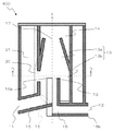
次に、本発明の実施の形態5に係る集塵ユニット400について、図12及び図13を用いて説明する。本実施の形態5は、旋回室13の構造が実施の形態4とは異なる。以下、特に説明しない限り、実施の形態1と同一の構成には同一の符号を付し、説明を繰り返さない。
Embodiment 5. FIG.
Next, a dust collection unit 400 according to Embodiment 5 of the present invention will be described with reference to FIGS. 12 and 13. The fifth embodiment is different from the fourth embodiment in the structure of the swirl chamber 13. Hereinafter, unless otherwise described, the same reference numerals are given to the same components as those in the first embodiment, and description thereof will not be repeated.

図12に示すように、旋回室13の側壁には、0次開口20が形成されている。0次開口20は、円筒部13b及び円錐部13cの間に形成されている。0次開口20は、1次集塵室14よりも旋回室13の軸方向下方に形成されている。すなわち、0次開口20は旋回室13の下流側の側面に形成されている。   As shown in FIG. 12, a zero-order opening 20 is formed on the side wall of the swirl chamber 13. The zero-order opening 20 is formed between the cylindrical portion 13b and the conical portion 13c. The zero-order opening 20 is formed below the primary dust collection chamber 14 in the axial direction of the swirl chamber 13. That is, the zero-order opening 20 is formed on the downstream side surface of the swirl chamber 13.

集塵ユニット400は、例えば円筒形状を呈する0次集塵室21を備えている。なお、0次集塵室21の形状はこれに限定されない。0次集塵室21は、旋回室13の外周に設けられている。0次集塵室21の少なくとも一部は、1次集塵室14よりも旋回室13の軸方向下方に設けられている。0次集塵室21は、0次開口20を介して旋回室13の内部と連通し、0次開口20から流入した塵埃を捕集する。   The dust collection unit 400 includes a zero-order dust collection chamber 21 having a cylindrical shape, for example. The shape of the zero-order dust collection chamber 21 is not limited to this. The zero-order dust collection chamber 21 is provided on the outer periphery of the swirl chamber 13. At least a part of the zero-order dust collection chamber 21 is provided below the primary dust collection chamber 14 in the axial direction of the swirl chamber 13. The zero-order dust collection chamber 21 communicates with the inside of the swirl chamber 13 through the zero-order opening 20 and collects dust flowing in from the zero-order opening 20.

次に、図13を参照して0次開口20と0次集塵室21との配置について説明する。0次開口20は旋回室13の一部を開口して形成されている。0次集塵室21は、旋回室13の外周に設けられている。   Next, the arrangement of the zero-order opening 20 and the zero-order dust collection chamber 21 will be described with reference to FIG. The zero-order opening 20 is formed by opening a part of the swirl chamber 13. The zero-order dust collection chamber 21 is provided on the outer periphery of the swirl chamber 13.

次に、集塵ユニット400の機能を具体的に説明する。ユニット流入口11から斜め上方向に向けて旋回室13内に流入した含塵空気は、旋回室13の内壁面に沿って旋回しながら上昇する。このとき、円筒部13bで比較的嵩の大きな塵埃が分離される。分離された塵埃は、0次開口20を通過して0次集塵室21に捕集される。そして、円錐部13cでは嵩の小さな塵埃が分離され、1次開口17を通過して1次集塵室14に捕集される。   Next, the function of the dust collection unit 400 will be specifically described. The dust-containing air that has flowed into the swirl chamber 13 from the unit inlet 11 toward the obliquely upward direction rises while swirling along the inner wall surface of the swirl chamber 13. At this time, relatively bulky dust is separated by the cylindrical portion 13b. The separated dust passes through the zeroth order opening 20 and is collected in the zeroth order dust collection chamber 21. Then, dust having a small volume is separated at the conical portion 13c, passes through the primary opening 17, and is collected in the primary dust collection chamber 14.

このように構成された集塵ユニット400にあっても、実施の形態1と同様の効果が得られる。   Even in the dust collection unit 400 configured as described above, the same effects as those of the first embodiment can be obtained.

また、0次開口20を、1次開口17よりも旋回室13の軸方向下方の側面に形成したので、重力の影響を受けて下方に落ちやすい塵埃が、0次開口20から0次集塵室21に捕集されるので、捕集効率を向上させることができる。   Further, since the zero-order opening 20 is formed on the side surface of the swirl chamber 13 below the primary opening 17 in the axial direction, dust that tends to fall down due to the influence of gravity is collected from the zero-order opening 20 to the zero-order dust collection. Since it is collected in the chamber 21, the collection efficiency can be improved.

なお、図14に示すように、流入管15を、流入口18に向かうに従って含塵空気が旋回室13の軸方向下方に向かうように傾斜させ、旋回室13の軸方向下方の端面を、流入口18から旋回室13内に流入した直後の含塵空気が旋回室13の軸方向下方に向かい、その後上方に向かうように傾斜させてもよい。   As shown in FIG. 14, the inflow pipe 15 is inclined so that the dust-containing air is directed downward in the axial direction of the swirl chamber 13 toward the inlet 18, and the axially lower end surface of the swirl chamber 13 is The dust-containing air immediately after flowing into the swirl chamber 13 from the inlet 18 may be inclined so as to be directed downward in the axial direction of the swirl chamber 13 and then directed upward.

また、0次集塵室21が円筒形状を呈する例について説明したが、例えば四角柱等の多角形、あるいは楕円筒状等の形状としてもよい。   Moreover, although the example in which the zero-order dust collection chamber 21 has a cylindrical shape has been described, the shape may be, for example, a polygonal shape such as a quadrangular prism or an elliptical cylindrical shape.

実施の形態6.
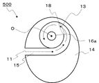
次に、本発明の実施の形態6に係る集塵ユニット500について、図15及び図16を用いて説明する。本実施の形態6は、流入管15の構造が実施の形態5とは異なる。以下、特に説明しない限り、実施の形態1と同一の構成には同一の符号を付し、説明を繰り返さない。
Embodiment 6 FIG.
Next, a dust collection unit 500 according to Embodiment 6 of the present invention will be described with reference to FIGS. 15 and 16. In the sixth embodiment, the structure of the inflow pipe 15 is different from that of the fifth embodiment. Hereinafter, unless otherwise described, the same reference numerals are given to the same components as those in the first embodiment, and description thereof will not be repeated.

図15に示すように、流入管15は、旋回室13の側壁に沿う湾曲した形状として構成されている。このとき、流入管15は旋回室13の軸を中心とする螺旋形状を有する。流入管15は、下流側に向かうにつれて旋回室13の軸方向上方に向かうように傾斜して形成されている。また、図16に示すように、流入管15は旋回室13の外周を覆うように形成されている。   As shown in FIG. 15, the inflow pipe 15 is configured as a curved shape along the side wall of the swirl chamber 13. At this time, the inflow pipe 15 has a spiral shape centering on the axis of the swirl chamber 13. The inflow pipe 15 is formed to be inclined so as to go upward in the axial direction of the swirl chamber 13 toward the downstream side. As shown in FIG. 16, the inflow pipe 15 is formed so as to cover the outer periphery of the swirl chamber 13.

このように構成された集塵ユニット500にあっても、実施の形態1と同様の効果が得られる。   Even in the dust collection unit 500 configured in this way, the same effect as in the first embodiment can be obtained.

また、流入管15を旋回室13の側壁に沿う湾曲した形状として構成したので、含塵空気の風路が形成され、上向きの流れが強められる。すなわち、重力の影響を受けて下方に落ちやすい塵埃が、旋回室13の上方に形成された1次開口17へ運ばれ1次集塵室14に捕集されやすくなるので、塵埃の捕集効率を向上させることができる。   Moreover, since the inflow pipe 15 is configured as a curved shape along the side wall of the swirl chamber 13, a wind path for dust-containing air is formed, and the upward flow is strengthened. That is, dust that tends to fall downward due to the influence of gravity is easily carried to the primary opening 17 formed above the swirl chamber 13 and collected in the primary dust collection chamber 14, so that dust collection efficiency is improved. Can be improved.

なお、上記した実施の形態1及び2では、旋回室13が円筒状を呈する例について説明したが、それぞれ旋回室13が円筒部13b及び円錐部13cで構成されるものとしてもよい。   In Embodiments 1 and 2, the example in which the swirl chamber 13 has a cylindrical shape has been described. However, the swirl chamber 13 may include a cylindrical portion 13b and a conical portion 13c, respectively.

また、上記した実施の形態3から6では、旋回室が円筒部13b及び円錐部13cで構成される例について説明したが、旋回室13全体が円筒状を呈するものとしてもよい。   Moreover, in above-mentioned Embodiment 3-6, although the turning chamber demonstrated the example comprised by the cylindrical part 13b and the cone part 13c, the turning room 13 whole is good also as what exhibits a cylindrical shape.

さらに、上記した実施の形態3から6では、排出管16における上流側の端部16aが、旋回室13の軸方向下方の端面から旋回室13の内部に突出するように設けられている例について説明したが、端部16aが旋回室13の軸方向上方の端面から旋回室13の内部に突出するように設けられるものとしてもよい。   Furthermore, in the above-described third to sixth embodiments, an example in which the upstream end 16a of the discharge pipe 16 is provided so as to protrude from the axially lower end surface of the swirl chamber 13 into the swirl chamber 13 is provided. Although described, the end portion 16a may be provided so as to protrude from the end surface in the axial direction of the swirl chamber 13 into the swirl chamber 13.

また、上記した実施の形態1から6において、排出管16が円筒部及び円錐部を有し、壁面に通気を行なうための微細孔が形成されていてもよい。この微細孔が排出口19となる。   In the above-described first to sixth embodiments, the discharge pipe 16 may have a cylindrical portion and a conical portion, and fine holes for venting the wall surface may be formed. This fine hole becomes the discharge port 19.

さらに、上記した実施の形態1から6において、旋回室13の軸方向下方の端面及び流入管15の両方が旋回室13の軸に対して傾斜している例について説明したが、いずれか一方を傾斜させるものとしてもよい。   Further, in the first to sixth embodiments described above, the example in which both the axially lower end surface of the swirl chamber 13 and the inflow pipe 15 are inclined with respect to the shaft of the swirl chamber 13 has been described. It may be inclined.

また、上記した実施の形態1から6において、旋回室13の中心軸Oが本体ユニット7の幅方向中央からずれた位置に配置されている例について説明したが、図17に示すように中心軸Oが本体ユニット7の幅方向中央に配置されるものとしてもよい。   In the first to sixth embodiments described above, the example in which the central axis O of the swirl chamber 13 is arranged at a position shifted from the center in the width direction of the main unit 7 has been described. However, as shown in FIG. O may be arranged at the center in the width direction of the main unit 7.

さらに、上記した実施の形態1から6において、旋回室13の軸線Xが鉛直方向に延びるように集塵ユニット6を本体ユニット7に搭載する例について説明したが、図18に示すように、旋回室13の軸線Xが鉛直方向に対して傾斜するように集塵ユニット6を配置するものとしてもよい。すなわち、本体ユニット7の高さ方向に対して、旋回室13の軸線Xが傾斜するものとしてもよい。このとき、流入口18および排出口19の位置関係は、傾斜した軸線Xの方向に基づいて判断される。   Furthermore, in Embodiments 1 to 6 described above, the example in which the dust collection unit 6 is mounted on the main unit 7 so that the axis X of the swirl chamber 13 extends in the vertical direction has been described. As shown in FIG. The dust collection unit 6 may be arranged so that the axis X of the chamber 13 is inclined with respect to the vertical direction. That is, the axis X of the swirl chamber 13 may be inclined with respect to the height direction of the main unit 7. At this time, the positional relationship between the inlet 18 and the outlet 19 is determined based on the direction of the inclined axis X.

さらに、上記した実施の形態1から6において、キャニスタータイプの電気掃除機の例について説明したが、本発明を他のタイプの電気掃除機に適用してもよい。   Furthermore, in Embodiment 1-6 mentioned above, although the example of the canister type vacuum cleaner was demonstrated, you may apply this invention to another type of vacuum cleaner.

1 掃除機本体(電気掃除機)、2 吸込具、3 吸引パイプ、4 接続パイプ、5 吸引ホース(ホース)、6 集塵ユニット(サイクロン分離装置)、7 本体ユニット(本体)、8 取っ手、9 操作スイッチ、10 本体吸引口(接続口)、11 ユニット流入口、12 ユニット排出口、13 旋回室、13a 端面、13b 円筒部、13c 円錐部、14 1次集塵室、15 流入管、16 排出管、17 1次開口、18 流入口、19 排出口、20 0次開口、21 0次集塵室、100 集塵ユニット、200 集塵ユニット、300 集塵ユニット、400 集塵ユニット、500 集塵ユニット DESCRIPTION OF SYMBOLS 1 Vacuum cleaner body (electric vacuum cleaner), 2 suction tool, 3 suction pipe, 4 connection pipe, 5 suction hose (hose), 6 dust collecting unit (cyclone separator), 7 body unit (main body), 8 handle, 9 Operation switch, 10 Main body suction port (connection port), 11 Unit inflow port, 12 Unit discharge port, 13 Swivel chamber, 13a End surface, 13b Cylindrical portion, 13c Conical portion, 14 Primary dust collection chamber, 15 Inlet pipe, 16 Discharge Pipe, 17 Primary opening, 18 Inlet, 19 Outlet, 20 0th order opening, 210 0th order dust collection chamber, 100 Dust collection unit, 200 Dust collection unit, 300 Dust collection unit, 400 Dust collection unit, 500 Dust collection unit

Claims (11)

サイクロン分離装置を搭載した本体と、前記本体に形成された接続口を介して前記サイクロン分離装置と連通し、内部に含塵空気を流通させるホースと、を備えた電気掃除機において、
前記サイクロン分離装置は、
流入口および排出口が形成され、前記含塵空気を旋回させて空気と塵埃とに分離する筒状の旋回室と、
前記流入口を介して前記旋回室に前記含塵空気を流入させる流入管と、
前記排出口を介して前記旋回室内から前記空気を排出する排出管と、を備え、
前記接続口は、前記本体の高さ方向の中心よりも下方に形成され、前記接続口の開口面は、前記流入管の上流側端部の開口面と対向し、かつ隣接して配置され、
前記流入口は、前記排出口よりも前記旋回室の軸方向下方に配置され、
前記流入管が、前記旋回室の軸方向に対して傾斜している電気掃除機。
In a vacuum cleaner comprising: a main body equipped with a cyclone separator; and a hose that communicates with the cyclone separator via a connection port formed in the main body and circulates dust-containing air therein.
The cyclone separator is
A cylindrical swirl chamber in which an inflow port and a discharge port are formed, and the dust-containing air is swirled and separated into air and dust;
An inflow pipe for allowing the dust-containing air to flow into the swirl chamber through the inflow port;
A discharge pipe for discharging the air from the swirl chamber through the discharge port,
The connection port is formed below the center in the height direction of the main body, the opening surface of the connection port is opposed to and is adjacent to the opening surface of the upstream end of the inflow pipe,
The inflow port is disposed below the discharge port in the axial direction of the swirl chamber,
A vacuum cleaner in which the inflow pipe is inclined with respect to the axial direction of the swirl chamber.
前記流入管の上流側端部が、前記流入口よりも前記旋回室の軸方向下方に配置される請求項1に記載の電気掃除機。   The vacuum cleaner according to claim 1, wherein an upstream end portion of the inflow pipe is disposed below the inflow port in an axial direction of the swirl chamber. 前記流入口または前記流入管に、前記電気掃除機の運転停止中に前記流入口または前記流入管を閉塞する弁が設けられた請求項2に記載の電気掃除機。   The vacuum cleaner according to claim 2, wherein the inlet or the inlet pipe is provided with a valve that closes the inlet or the inlet pipe when the vacuum cleaner is stopped. 前記流入管の上流側端部が、前記流入口よりも前記旋回室の軸方向上方に配置される請求項1に記載の電気掃除機。   The vacuum cleaner according to claim 1, wherein an upstream end portion of the inflow pipe is disposed above the swirl chamber in an axial direction with respect to the inflow port. サイクロン分離装置を搭載した本体と、前記本体に形成された接続口を介して前記サイクロン分離装置と連通し、内部に含塵空気を流通させるホースと、を備えた電気掃除機において、
前記サイクロン分離装置は、
流入口および排出口が形成され、前記含塵空気を旋回させて空気と塵埃とに分離する筒状の旋回室と、
前記流入口を介して前記旋回室に前記含塵空気を流入させる流入管と、
前記排出口を介して前記旋回室内から前記空気を排出する排出管と、を備え、
前記接続口は、前記本体の高さ方向の中心よりも下方に形成され、前記接続口の開口面は、前記流入管の上流側端部の開口面と対向し、かつ隣接して配置され、
前記流入口は、前記排出口よりも前記旋回室の軸方向下方に配置され、
前記旋回室の軸方向下方の端面が、前記旋回室の軸方向に対して傾斜している電気掃除機。
In a vacuum cleaner comprising: a main body equipped with a cyclone separator; and a hose that communicates with the cyclone separator via a connection port formed in the main body and circulates dust-containing air therein.
The cyclone separator is
A cylindrical swirl chamber in which an inflow port and a discharge port are formed, and the dust-containing air is swirled and separated into air and dust;
An inflow pipe for allowing the dust-containing air to flow into the swirl chamber through the inflow port;
A discharge pipe for discharging the air from the swirl chamber through the discharge port,
The connection port is formed below the center in the height direction of the main body, the opening surface of the connection port is opposed to and is adjacent to the opening surface of the upstream end of the inflow pipe,
The inflow port is disposed below the discharge port in the axial direction of the swirl chamber,
The vacuum cleaner in which an axially lower end surface of the swirl chamber is inclined with respect to the axial direction of the swirl chamber.
前記端面の少なくとも一部が、前記流入管から流入した含塵空気の下流側に向かうに従って、前記旋回室の軸方向上方に傾斜する請求項5に記載の電気掃除機。   The vacuum cleaner according to claim 5, wherein at least a part of the end surface is inclined upward in the axial direction of the swirl chamber as it goes downstream of the dust-containing air flowing in from the inflow pipe. 前記端面の少なくとも一部が、前記流入管から流入した含塵空気の下流側に向かうに従って、前記旋回室の軸方向下方に傾斜する請求項5または6に記載の電気掃除機。   The vacuum cleaner according to claim 5 or 6, wherein at least a part of the end face is inclined downward in the axial direction of the swirl chamber as it goes downstream of the dust-containing air flowing in from the inflow pipe. 前記端面が、前記旋回室の軸を中心とする螺旋状曲面を有する請求項5から7のいずれか一項に記載の電気掃除機。   The vacuum cleaner according to any one of claims 5 to 7, wherein the end surface has a spiral curved surface centering on an axis of the swirl chamber. 前記旋回室の側壁の一部に形成される0次開口と、前記0次開口を介して前記旋回室と連通し塵埃を捕集する0次集塵室とを更に備え、
前記0次集塵室が前記旋回室の外周部に設けられる請求項1から8のいずれか一項に記載の電気掃除機。
A zero-order opening formed in a part of the side wall of the swirl chamber, and a zero-order dust collection chamber that communicates with the swirl chamber through the zero-order opening and collects dust;
The vacuum cleaner according to any one of claims 1 to 8, wherein the zero-order dust collection chamber is provided on an outer peripheral portion of the swirl chamber.
前記流入管は、前記旋回室の軸を中心とする螺旋形状を有する請求項1から9のいずれか一項に記載の電気掃除機。   The vacuum cleaner according to any one of claims 1 to 9, wherein the inflow pipe has a spiral shape centering on an axis of the swirl chamber. 前記旋回室が円筒部と円錐部とを有している請求項1から10のいずれか一項に記載の電気掃除機。   The vacuum cleaner according to any one of claims 1 to 10, wherein the swirl chamber has a cylindrical portion and a conical portion.
JP2017106135A 2017-05-30 2017-05-30 Vacuum cleaner with cyclone separator Pending JP2018198902A (en)

Priority Applications (1)

Application Number Priority Date Filing Date Title
JP2017106135A JP2018198902A (en) 2017-05-30 2017-05-30 Vacuum cleaner with cyclone separator

Applications Claiming Priority (1)

Application Number Priority Date Filing Date Title
JP2017106135A JP2018198902A (en) 2017-05-30 2017-05-30 Vacuum cleaner with cyclone separator

Publications (1)

Publication Number Publication Date
JP2018198902A true JP2018198902A (en) 2018-12-20

Family

ID=64667452

Family Applications (1)

Application Number Title Priority Date Filing Date
JP2017106135A Pending JP2018198902A (en) 2017-05-30 2017-05-30 Vacuum cleaner with cyclone separator

Country Status (1)

Country Link
JP (1) JP2018198902A (en)

Citations (7)

* Cited by examiner, † Cited by third party
Publication number Priority date Publication date Assignee Title
JPS5584162U (en) * 1978-12-07 1980-06-10
JP2006192247A (en) * 2005-01-14 2006-07-27 Samsung Kwangju Electronics Co Ltd Cyclone dust-separating apparatus
JP2008272021A (en) * 2007-04-25 2008-11-13 Toshiba Corp Dust collection device and vacuum cleaner
JP2012504495A (en) * 2008-10-03 2012-02-23 ビーイー・エアロスペース・インコーポレーテッド Vortex separation device and method for taking air stream without moisture from waste stream
JP2013146318A (en) * 2012-01-18 2013-08-01 Hitachi Appliances Inc Vacuum cleaner
JP2014128393A (en) * 2012-12-28 2014-07-10 Toshiba Corp Vacuum cleaner and dust separating device
JP2014212865A (en) * 2013-04-24 2014-11-17 日立アプライアンス株式会社 Vacuum cleaner

Patent Citations (7)

* Cited by examiner, † Cited by third party
Publication number Priority date Publication date Assignee Title
JPS5584162U (en) * 1978-12-07 1980-06-10
JP2006192247A (en) * 2005-01-14 2006-07-27 Samsung Kwangju Electronics Co Ltd Cyclone dust-separating apparatus
JP2008272021A (en) * 2007-04-25 2008-11-13 Toshiba Corp Dust collection device and vacuum cleaner
JP2012504495A (en) * 2008-10-03 2012-02-23 ビーイー・エアロスペース・インコーポレーテッド Vortex separation device and method for taking air stream without moisture from waste stream
JP2013146318A (en) * 2012-01-18 2013-08-01 Hitachi Appliances Inc Vacuum cleaner
JP2014128393A (en) * 2012-12-28 2014-07-10 Toshiba Corp Vacuum cleaner and dust separating device
JP2014212865A (en) * 2013-04-24 2014-11-17 日立アプライアンス株式会社 Vacuum cleaner

Similar Documents

Publication Publication Date Title
JP6519665B2 (en) Electric vacuum cleaner
JP5306968B2 (en) Electric vacuum cleaner
US9155435B2 (en) Cyclone separation device and electric vacuum cleaner
JP4947161B2 (en) Cyclone separation device and vacuum cleaner
KR101073503B1 (en) Vacuum cleaner
KR100934668B1 (en) Dust collector of vacuum cleaner
JP4978685B2 (en) Electric vacuum cleaner
JP2011160820A (en) Cyclone separator device and vacuum cleaner
WO2020024537A1 (en) Spiral dust and gas separating device and gas purification device
JP6402365B2 (en) Electric vacuum cleaner
JP5376030B2 (en) Electric vacuum cleaner
JP2020506744A (en) Separation system for vacuum cleaner, and vacuum cleaner with separation system
JP5126274B2 (en) Cyclone separation device and vacuum cleaner
JP2018198902A (en) Vacuum cleaner with cyclone separator
JP5831519B2 (en) Cyclone separation device and vacuum cleaner
JP4968313B2 (en) Electric vacuum cleaner
JP5821980B2 (en) Centrifuge
JP5804033B2 (en) Cyclone separation device and vacuum cleaner
JP5472417B1 (en) Centrifuge
JP6443462B2 (en) Cyclone separation device and vacuum cleaner
JP5958632B2 (en) Electric vacuum cleaner
JP5958631B2 (en) Electric vacuum cleaner
JP5983800B2 (en) Cyclone separation device and vacuum cleaner
JP6128140B2 (en) Cyclone separation device and vacuum cleaner
KR20080022350A (en) Vaccum cleaner and dust seperating apparatus thereof

Legal Events

Date Code Title Description
RD04 Notification of resignation of power of attorney

Free format text: JAPANESE INTERMEDIATE CODE: A7424

Effective date: 20190909

A621 Written request for application examination

Free format text: JAPANESE INTERMEDIATE CODE: A621

Effective date: 20200318

A131 Notification of reasons for refusal

Free format text: JAPANESE INTERMEDIATE CODE: A131

Effective date: 20210202

A977 Report on retrieval

Free format text: JAPANESE INTERMEDIATE CODE: A971007

Effective date: 20210203

A02 Decision of refusal

Free format text: JAPANESE INTERMEDIATE CODE: A02

Effective date: 20210803