BRPI0820419B1 - air filter cartridges and air filter assemblies - Google Patents
air filter cartridges and air filter assemblies Download PDFInfo
- Publication number
- BRPI0820419B1 BRPI0820419B1 BRPI0820419-5A BRPI0820419A BRPI0820419B1 BR PI0820419 B1 BRPI0820419 B1 BR PI0820419B1 BR PI0820419 A BRPI0820419 A BR PI0820419A BR PI0820419 B1 BRPI0820419 B1 BR PI0820419B1
- Authority
- BR
- Brazil
- Prior art keywords
- housing
- air
- filter cartridge
- filter
- cartridge
- Prior art date
Links
Images


Classifications
-
- B—PERFORMING OPERATIONS; TRANSPORTING
- B01—PHYSICAL OR CHEMICAL PROCESSES OR APPARATUS IN GENERAL
- B01D—SEPARATION
- B01D46/00—Filters or filtering processes specially modified for separating dispersed particles from gases or vapours
- B01D46/52—Particle separators, e.g. dust precipitators, using filters embodying folded corrugated or wound sheet material
- B01D46/521—Particle separators, e.g. dust precipitators, using filters embodying folded corrugated or wound sheet material using folded, pleated material
- B01D46/525—Particle separators, e.g. dust precipitators, using filters embodying folded corrugated or wound sheet material using folded, pleated material which comprises flutes
- B01D46/526—Particle separators, e.g. dust precipitators, using filters embodying folded corrugated or wound sheet material using folded, pleated material which comprises flutes in stacked arrangement
-
- B—PERFORMING OPERATIONS; TRANSPORTING
- B01—PHYSICAL OR CHEMICAL PROCESSES OR APPARATUS IN GENERAL
- B01D—SEPARATION
- B01D46/00—Filters or filtering processes specially modified for separating dispersed particles from gases or vapours
- B01D46/0002—Casings; Housings; Frame constructions
- B01D46/0004—Details of removable closures, lids, caps or filter heads
-
- B—PERFORMING OPERATIONS; TRANSPORTING
- B01—PHYSICAL OR CHEMICAL PROCESSES OR APPARATUS IN GENERAL
- B01D—SEPARATION
- B01D46/00—Filters or filtering processes specially modified for separating dispersed particles from gases or vapours
- B01D46/0002—Casings; Housings; Frame constructions
- B01D46/0005—Mounting of filtering elements within casings, housings or frames
-
- B—PERFORMING OPERATIONS; TRANSPORTING
- B01—PHYSICAL OR CHEMICAL PROCESSES OR APPARATUS IN GENERAL
- B01D—SEPARATION
- B01D46/00—Filters or filtering processes specially modified for separating dispersed particles from gases or vapours
- B01D46/10—Particle separators, e.g. dust precipitators, using filter plates, sheets or pads having plane surfaces
-
- B—PERFORMING OPERATIONS; TRANSPORTING
- B01—PHYSICAL OR CHEMICAL PROCESSES OR APPARATUS IN GENERAL
- B01D—SEPARATION
- B01D46/00—Filters or filtering processes specially modified for separating dispersed particles from gases or vapours
- B01D46/24—Particle separators, e.g. dust precipitators, using rigid hollow filter bodies
- B01D46/2403—Particle separators, e.g. dust precipitators, using rigid hollow filter bodies characterised by the physical shape or structure of the filtering element
- B01D46/2411—Filter cartridges
- B01D46/2414—End caps including additional functions or special forms
-
- B—PERFORMING OPERATIONS; TRANSPORTING
- B01—PHYSICAL OR CHEMICAL PROCESSES OR APPARATUS IN GENERAL
- B01D—SEPARATION
- B01D46/00—Filters or filtering processes specially modified for separating dispersed particles from gases or vapours
- B01D46/56—Filters or filtering processes specially modified for separating dispersed particles from gases or vapours with multiple filtering elements, characterised by their mutual disposition
- B01D46/62—Filters or filtering processes specially modified for separating dispersed particles from gases or vapours with multiple filtering elements, characterised by their mutual disposition connected in series
-
- B—PERFORMING OPERATIONS; TRANSPORTING
- B01—PHYSICAL OR CHEMICAL PROCESSES OR APPARATUS IN GENERAL
- B01D—SEPARATION
- B01D2271/00—Sealings for filters specially adapted for separating dispersed particles from gases or vapours
- B01D2271/02—Gaskets, sealings
- B01D2271/027—Radial sealings
-
- Y—GENERAL TAGGING OF NEW TECHNOLOGICAL DEVELOPMENTS; GENERAL TAGGING OF CROSS-SECTIONAL TECHNOLOGIES SPANNING OVER SEVERAL SECTIONS OF THE IPC; TECHNICAL SUBJECTS COVERED BY FORMER USPC CROSS-REFERENCE ART COLLECTIONS [XRACs] AND DIGESTS
- Y10—TECHNICAL SUBJECTS COVERED BY FORMER USPC
- Y10T—TECHNICAL SUBJECTS COVERED BY FORMER US CLASSIFICATION
- Y10T156/00—Adhesive bonding and miscellaneous chemical manufacture
- Y10T156/10—Methods of surface bonding and/or assembly therefor
Abstract
ARRANJOS, CONJUNTOS E MÉTODOS DE FILTRO DE AR. São descritos conjuntos limpadores de ar e componentes destes. E descrito um primeiro cartucho de filtro ou principal exemplar que inclui um pacote de meio que compreende tiras de material estriado preso em folhas de revestimento orientadas em uma pilha. O pacote de meio define revestimentos do fluxo de entrada e de saída opostos, com estrias se estendendo em uma direção entre eles. O pacote de meio é preso de forma no removível em um alojamento do cartucho de filtro, em um local entre seções opostas de um invólucro, tipicamente, preso a ele com um adesivo. O invólucro também define uma extremidade fechada, espaçada, mas em sobreposição com o revestimento de extremidade de saída do pacote de meio. Tipicamente, a extremidade fechada é curva e, tipicamente, o invólucro provê tanto uma forma de d/b quanto uma forma de u. O filtro inclui um elemento de extremidade, com um arranjo de abertura do fluxo de saída, permitindo o fluxo de saída do cartucho de filtro em uma direção, no geral, ortogonal ao fluxo de ar através do pacote de meio.O conjunto limpador de ar inclui um alojamento com recursos para recepção (...).AIR FILTER ARRANGEMENTS, SETS AND METHODS. Air cleaner assemblies and components thereof are described. A first exemplary filter or main cartridge is described which includes a medium pack comprising strips of striated material attached to coating sheets oriented in a stack. The media pack defines opposing inlet and outlet liners, with streaks extending in a direction between them. The media pack is non-removably attached to a filter cartridge housing, in a location between opposite sections of a housing, typically attached to it with an adhesive. The enclosure also defines a closed, spaced end, but in overlap with the outlet end liner of the media pack. Typically, the closed end is curved and, typically, the housing provides both a d / b shape and a u shape. The filter includes an end element, with an outlet flow opening arrangement, allowing the filter cartridge to flow out in a direction, generally orthogonal to the air flow through the media pack. includes accommodation with reception facilities (...).
Description
[001] Este pedido está sendo depositado em 13 de novembro de 2008, como um pedido de patente internacional PCT em nome de Donaldson Company, Inc., uma empresa nacional dos EUA, requerente da designação de todos os países, exceto os EUA, e Benny Kevin Nelson, John David Kuhn, Donald Duane Larson e David Wayne Nelson, todos cidadãos dos EUA, requerentes da designação nos EUA somente, e reivindica a prioridade ao pedido provisório de patente US 61/003.215, depositado em 15 de novembro de 2007, e pedido provisório de patente US 61/130.790, depositado em 2 de junho de 2008, ambos os quais são aqui incorporados pela referência.[001] This application is being filed on November 13, 2008, as an international PCT patent application in the name of Donaldson Company, Inc., a US national company, applicant for designation of all countries except the USA, and Benny Kevin Nelson, John David Kuhn, Donald Duane Larson and David Wayne Nelson, all US citizens, applicants for the US designation only, and claims priority to provisional US patent application 61 / 003,215, filed on November 15, 2007, and provisional patent application US 61 / 130,790, filed on June 2, 2008, both of which are incorporated herein by reference.
[002] A presente divulgação diz respeito a arranjos de filtro para uso na filtragem de ar. Particularmente, a divulgação diz respeito a arranjo de filtro com meios filtrantes que usam meio de filtro-z da forma aqui caracterizada. Mais especificamente, a divulgação diz respeito a tais meios filtrantes e sua inclusão em arranjos de cartucho de filtro de ar reparáveis, tipicamente, para uso em filtros de ar (conjuntos de filtro de ar). Arranjos de filtro de ar e métodos de montagem e uso também são descritos.[002] The present disclosure concerns filter arrangements for use in air filtration. In particular, the disclosure relates to filter arrangement with filter media that use z-filter medium in the manner characterized here. More specifically, the disclosure concerns such filter media and their inclusion in repairable air filter cartridge arrangements, typically for use in air filters (air filter assemblies). Air filter arrangements and methods of assembly and use are also described.
[003] Correntes de ar podem carregar material contaminante. Em muitos casos, é desejado filtrar parte ou todo o material contaminante da corrente de ar. Por exemplo, correntes de ar para motores (por exemplo, ar de combustão) para veículos motorizados ou para equipamento de geração de energia, correntes de gás para sistemas de turbina a gás e correntes de ar para vários fornos de combustão carregam particulado contaminante que deve ser filtrado. É preferível em tais sistemas que material contaminante seleciona- do seja removido do (ou tenha seu nível reduzido no) ar. Uma variedade de arranjos de filtro de ar foi desenvolvida para coleta de contaminante. Melhorias são procuradas.[003] Drafts can carry contaminating material. In many cases, it is desired to filter some or all of the contaminating material from the air stream. For example, drafts for engines (for example, combustion air) for motor vehicles or for power generation equipment, gas streams for gas turbine systems and drafts for various combustion furnaces carry contaminant particulate which must be filtered. It is preferable in such systems that the selected contaminant material is removed from (or reduced in air) level. A variety of air filter arrangements have been developed for collecting contaminants. Improvements are sought.
[004] De acordo com a presente divulgação, conjuntos (arranjos) de filtro de ar e componentes destes são descritos. Como um exemplo, é descrito um primeiro cartucho de filtro de ar usado como um componente de manutenção no conjunto de filtro de ar. No geral, o primeiro cartucho de filtro de ar compreende um meio filtrante posicionado em um alojamento do cartucho de filtro. Tipicamente, o meio filtrante fica posicionado de forma não removível no alojamento do cartucho de filtro.[004] In accordance with the present disclosure, air filter assemblies and components thereof are described. As an example, a first air filter cartridge used as a maintenance component in the air filter assembly is described. In general, the first air filter cartridge comprises a filter medium positioned in a filter cartridge housing. Typically, the filter medium is positioned non-removably in the housing of the filter cartridge.
[005] Tipicamente, o meio filtrante é um meio filtrante de filtro-z e tem uma face de fluxo de entrada e uma face oposta de fluxo de saída. O meio filtrante fica posicionado em um invólucro ou elemento de invólucro do alojamento do cartucho de filtro com a face de fluxo de saída voltada para a direção de uma extremidade fechada do invólucro; o invólucro tendo primeira e segunda seções laterais e uma seção de extremidade fechada. Os invólucros exemplares representados têm tanto uma forma de d/b quanto uma forma de u. Em cada caso, tipicamente, o invólucro tem lados abertos, fechados no alojamento do cartucho de filtro por um primeiro e um segundo elementos de extremidade opostos.[005] Typically, the filter medium is a z-filter medium and has an incoming flow face and an opposite outgoing flow face. The filter medium is positioned in a housing or housing element of the filter cartridge housing with the outlet flow face facing towards a closed end of the housing; the housing having first and second side sections and a closed end section. The exemplary wrappings depicted have both a d / b shape and a u shape. In each case, typically, the housing has open sides, closed in the filter cartridge housing by an opposing first and second end member.
[006] O primeiro elemento de extremidade fica posicionado sobre um primeiro lado do meio filtrante e do invólucro. No geral, o primeiro elemento de extremidade: inclui um arranjo de saída do fluxo de ar através de si, em comunicação fluídica com um volume de ar limpo definido entre a extremidade fechada do invólucro e a face de fluxo de saída do meio filtrante; e fecha um pri- meiro lado do meio filtrante.[006] The first end element is positioned on a first side of the filter medium and the housing. In general, the first end element: includes an airflow outlet arrangement through itself, in fluid communication with a clean air volume defined between the closed end of the housing and the outlet flow face of the filter medium; and closes the first side of the filter medium.
[007] O segundo elemento de extremidade fica posicionado oposto ao primeiro elemento de extremidade e fecha um segundo lado do invólucro e do meio filtrante, oposto ao primeiro lado. Tipicamente, o segundo elemento de extremidade é fechado para a passagem de ar através de si.[007] The second end element is positioned opposite the first end element and closes a second side of the casing and filter medium, opposite the first side. Typically, the second end member is closed for air to pass through it.
[008] O cartucho de filtro resultante pode ser provido com um arranjo de vedação do alojamento ao redor do arranjo de saída do fluxo de ar. Em um exemplo, o arranjo de vedação do alojamento compreende um arranjo de vedação radial moldado no local como parte da primeira modalidade; um exemplo específico sendo um arranjo de vedação radial direcionado para dentro, embora alternativas sejam possíveis.[008] The resulting filter cartridge can be provided with a housing sealing arrangement around the airflow outlet arrangement. In one example, the housing sealing arrangement comprises a radial sealing arrangement molded in place as part of the first embodiment; a specific example being an inward-facing radial seal arrangement, although alternatives are possible.
[009] Também, em certas modalidades descritas, o segundo elemento inclui um elemento de vedação do alojamento periférico, orientado para encaixar e vedar em uma parede lateral interior de um alojamento de filtro de ar.[009] Also, in certain described modalities, the second element includes a sealing element of the peripheral housing, oriented to fit and seal in an inner side wall of an air filter housing.
[010] Um conjunto de filtro de ar é configurado para receber operativamente o cartucho de filtro. Um alojamento de filtro de ar exemplar inclui um arranjo de entrada (ou entrada), um corpo do alojamento e um arranjo de saída do fluxo de ar (ou saída) orientado através do alojamento em uma direção do fluxo de ar, no geral, ortogonal a uma direção do fluxo de ar para o interior da extremidade de entrada. O alojamento pode incluir um flange ao redor do arranjo de saída, através do alojamento. O flange pode ficar posicionado para encaixe de vedação com um arranjo de vedação do alojamento no cartucho de filtro, orientado em associação com uma saída do fluxo de ar do cartucho de filtro.[010] An air filter assembly is configured to operatively receive the filter cartridge. An exemplary air filter housing includes an inlet (or inlet) arrangement, a housing body, and an airflow outlet (or outlet) arrangement oriented through the housing in a generally orthogonal airflow direction in a direction of air flow into the inlet end. The housing may include a flange around the outlet arrangement, through the housing. The flange can be positioned for sealing fit with a sealing arrangement of the housing on the filter cartridge, oriented in association with an outlet of the air flow from the filter cartridge.
[011] Um cartucho de filtro secundário ou de segurança opcional pode ficar posicionado vedado no alojamento, e se projetando para o interior do volume de ar limpo do primeiro cartucho de filtro.[011] An optional secondary or safety filter cartridge can be positioned sealed in the housing, and projecting into the clean air volume of the first filter cartridge.
[012] Em um melhor arranjo aqui caracterizado, a seção de extremidade fechada do invólucro inclui um arranjo de abertura de drenagem para permitir a drenagem de água de uma extremidade à jusante do cartucho de filtro. Em uma modalidade exemplar, interiormente em relação ao invólucro, o meio de filtro fica posicionado sobre o arranjo de abertura, já que o arranjo de abertura fica através do invólucro, no lado do ar limpo do cartucho de filtro. Assim, o meio de filtro fecha o invólucro neste local.[012] In a better arrangement characterized here, the closed end section of the housing includes a drain opening arrangement to allow water to drain from one end downstream of the filter cartridge. In an exemplary embodiment, internally in relation to the housing, the filter medium is positioned over the opening arrangement, since the opening arrangement is through the housing, on the clean air side of the filter cartridge. Thus, the filter means closes the housing at this location.
[013] Uma variedade de recursos específicos é descrita e mostrada.[013] A variety of specific features are described and shown.
[014] Percebe-se que não há exigência de que o conjunto ou componentes incluam todos os recursos individuais aqui caracterizados, a fim de obter alguma vantagem de acordo com a presente divulgação.[014] It is noticed that there is no requirement that the set or components include all the individual features featured here, in order to obtain any advantage in accordance with the present disclosure.
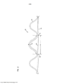
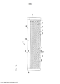
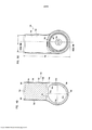
[015] A figura 1 é uma vista em perspectiva fragmentária, esquemática do meio de filtro-z exemplar usado em arranjos de acordo com a US 61/003.215.[015] Figure 1 is a fragmentary, schematic view of the exemplary z-filter medium used in arrangements in accordance with US 61 / 003.215.
[016] A figura 2 é uma vista seccional transversal ampliada esquemática de uma parte do meio representado na figura 1.[016] Figure 2 is an enlarged schematic cross-sectional view of a part of the middle shown in Figure 1.
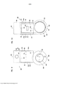
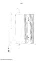
[017] A figura 3 inclui vistas esquemáticas de exemplos de várias definições de meio corrugado.[017] Figure 3 includes schematic views of examples of various definitions of corrugated medium.
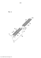
[018] A figura 4 é uma vista esquemática de um processo para fabricar meio de acordo com a presente divulgação.[018] Figure 4 is a schematic view of a process for manufacturing medium in accordance with the present disclosure.
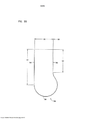
[019] A figura 5 é uma vista esquemática seccional transversal de uma sutura de extremidade opcional para estrias do meio usada nos arranjos aqui descritos.[019] Figure 5 is a schematic cross-sectional view of an optional end suture for middle striations used in the arrangements described here.
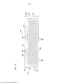
[020] A figura 6 é uma representação esquemática de uma etapa de criação um meio filtrante de filtro-z empilhado.[020] Figure 6 is a schematic representation of a step of creating a stacked z-filter media.
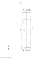
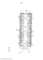
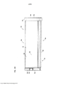
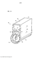
[021] A figura 7 é uma vista elevada lateral esquemática de um conjunto de filtro de ar que inclui recursos de acordo com a presente divulgação.[021] Figure 7 is a schematic side elevation view of an air filter assembly that includes features in accordance with the present disclosure.
[022] A figura 8 é uma vista plana de base esquemática do conjunto de filtro de ar da figura 7.[022] Figure 8 is a schematic plan view of the air filter assembly in Figure 7.
[023] A figura 9 é uma vista de saída e elevada esquemática do conjunto de filtro de ar da figura 7.[023] Figure 9 is an outlet and schematic elevation view of the air filter assembly in figure 7.
[024] A figura 10 é uma vista de acesso de extremidade elevada esquemática do conjunto de filtro de ar da figura 7; a vista da figura 10 estando voltada para uma extremidade oposta daquela da figura 9.[024] Figure 10 is a schematic high end access view of the air filter assembly of Figure 7; the view of figure 10 being facing an opposite end to that of figure 9.
[025] A figura 11 é uma vista plana de topo esquemática do conjunto de filtro de ar da figura 7.[025] Figure 11 is a schematic top plan view of the air filter assembly in Figure 7.
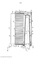
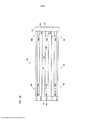
[026] A figura 12 é uma vista esquemática seccional transversal tomada ao longo da linha 12-12 da figura 8.[026] Figure 12 is a schematic cross-sectional view taken along line 12-12 in figure 8.
[027] A figura 12A é uma vista esquemática seccional transversal tomada, no geral, ao longo da linha 12A-12A da figura 12.[027] Figure 12A is a schematic cross-sectional view taken, in general, along
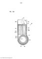
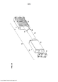
[028] A figura 13 é uma vista em perspectiva explodida esquemática do conjunto de filtro de ar da figura 7 tomada como uma seção transversal análoga à figura 12.[028] Figure 13 is a schematic exploded perspective view of the air filter assembly of figure 7 taken as a cross section analogous to figure 12.
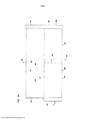
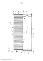
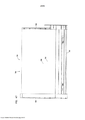
[029] A figura 14 é uma vista elevada lateral esquemática de um cartucho de filtro componente do conjunto das figuras 7-13.[029] Figure 14 is a schematic side elevation view of a filter cartridge component of the set of figures 7-13.
[030] A figura 15 é uma vista plana de base esquemática do cartucho de filtro da figura 14.[030] Figure 15 is a schematic plan view of the filter cartridge in figure 14.
[031] A figura 16 é uma vista plana de topo esquemática do cartucho de filtro da figura 14.[031] Figure 16 is a schematic top plan view of the filter cartridge in Figure 14.
[032] A figura 17 é uma vista elevada de extremidade de saída es- quemática do cartucho de filtro da figura 14.[032] Figure 17 is an elevated view of the schematic outlet end of the filter cartridge in Figure 14.
[033] A figura 18 é uma vista elevada de extremidade esquemática tomada na direção de uma extremidade oposta do cartucho da figura 14, a partir da vista da figura 17.[033] Figure 18 is a schematic end elevation taken in the direction of an opposite end of the cartridge in figure 14, from the view in figure 17.
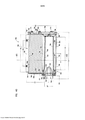
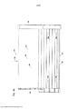
[034] A figura 19 é uma vista esquemática seccional transversal do cartucho de filtro da figura 14, tomado, no geral, na orientação correspondente à vista seccional transversal da figura 12 e, no geral, ao longo da linha 19-19 da figura 15.[034] Figure 19 is a schematic cross-sectional view of the filter cartridge in Figure 14, taken, in general, in the orientation corresponding to the cross-sectional view in Figure 12 and, in general, along line 19-19 in Figure 15 .
[035] A figura 20 é uma vista esquemática seccional transversal tomada, no geral, ao longo da linha 20-20 da figura 19.[035] Figure 20 is a schematic cross-sectional view taken, in general, along line 20-20 of figure 19.
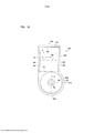
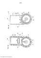
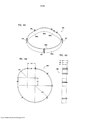
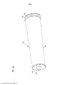
[036] A figura 21 é uma vista elevada lateral esquemática de um cartucho de filtro de segurança ou secundário usado no conjunto de filtro de ar das figuras 7-13.[036] Figure 21 is a schematic side elevation view of a safety or secondary filter cartridge used in the air filter assembly of figures 7-13.
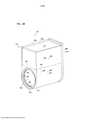
[037] A figura 22 é uma vista em perspectiva de topo esquemática da extremidade de saída de uma segunda modalidade de um conjunto de filtro de ar de acordo com a US 61/003.215.[037] Figure 22 is a schematic top perspective view of the outlet end of a second embodiment of an air filter assembly in accordance with US 61 / 003.215.
[038] A figura 23 é uma vista em perspectiva de topo esquemática da extremidade da cobertura de acesso do conjunto de filtro de ar da figura 22.[038] Figure 23 is a schematic top perspective view of the end of the access cover of the air filter assembly in Figure 22.
[039] A figura 24 é uma vista em perspectiva de base esquemática da extremidade de saída do conjunto de filtro de ar da figura 22.[039] Figure 24 is a schematic base perspective view of the outlet end of the air filter assembly in Figure 22.
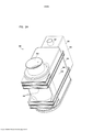
[040] A figura 25 é uma vista em perspectiva de topo esquemática, explodida da cobertura de acesso do conjunto de filtro de ar da figura 22.[040] Figure 25 is a schematic top perspective view, exploded from the access cover of the air filter assembly in Figure 22.
[041] A figura 26 é uma vista em perspectiva de topo esquemática, explodida da extremidade de saída do conjunto de filtro de ar da figura 22.[041] Figure 26 is a schematic top perspective view, exploded from the outlet end of the air filter assembly in Figure 22.
[042] A figura 27 é uma vista em perspectiva de topo, esquemática da extremidade fechada de um cartucho de filtro usado no conjunto de filtro de ar das figuras 22-26.[042] Figure 27 is a top perspective view, schematic of the closed end of a filter cartridge used in the air filter assembly of figures 22-26.
[043] A figura 28 é uma vista em perspectiva de topo esquemática da extremidade de saída do cartucho de filtro da figura 27.[043] Figure 28 is a schematic top perspective view of the outlet end of the filter cartridge in Figure 27.
[044] A figura 29 é uma vista elevada de extremidade de saída esquemática do cartucho de filtro das figuras 27-28.[044] Figure 29 is a schematic elevated end view of the filter cartridge of figures 27-28.
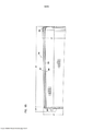
[045] A figura 30 é uma vista elevada lateral esquemática do cartucho de filtro das figuras 27-28, com linhas tracejadas indicando alguns detalhes internos.[045] Figure 30 is a schematic side elevation view of the filter cartridge in figures 27-28, with dashed lines indicating some internal details.
[046] A figura 31 é uma vista esquemática elevada de uma extremidade fechada do cartucho de filtro das figuras 27-30, com linhas tracejadas indicando, no geral, detalhes internos.[046] Figure 31 is a schematic elevated view of a closed end of the filter cartridge in figures 27-30, with dashed lines indicating, in general, internal details.
[047] A figura 32 é uma vista elevada esquemática da extremidade de acesso de uma terceira modalidade de um conjunto de filtro de ar de acordo com a presente divulgação.[047] Figure 32 is a schematic elevated view of the access end of a third embodiment of an air filter assembly in accordance with the present disclosure.
[048] A figura 33 é uma vista elevada esquemática da extremidade de saída do conjunto de filtro de ar da figura 32.[048] Figure 33 is a schematic elevated view of the outlet end of the air filter assembly in Figure 32.
[049] A figura 34 é uma vista elevada lateral esquemática do conjunto de filtro de ar das figuras 32 e 33, com partes rompidas para mostrar detalhes internos.[049] Figure 34 is a schematic side elevation view of the air filter assembly in figures 32 and 33, with broken parts to show internal details.
[050] A figura 35 é uma vista plana esquemática de topo da extremidade de acesso do conjunto de filtro de ar das figuras 32-34.[050] Figure 35 is a schematic top plan view of the access end of the air filter assembly of figures 32-34.
[051] A figura 36 é um vista plana esquemática da extremidade de base do conjunto de filtro de ar das figuras 32-35.[051] Figure 36 is a schematic plan view of the base end of the air filter assembly of figures 32-35.
[052] A figura 37 é uma segunda vista elevada lateral correspondente à figura 34.[052] Figure 37 is a second elevated side view corresponding to figure 34.
[053] A figura 38 é um vista em perspectiva esquemática da extremi- dade de topo de um conjunto de filtro de ar de acordo com as figuras 32-37.[053] Figure 38 is a schematic perspective view of the top end of an air filter assembly according to figures 32-37.
[054] A figura 39 é um vista em perspectiva esquemática, explodida do conjunto de filtro de ar da figura 38.[054] Figure 39 is a schematic perspective view, exploded of the air filter assembly in Figure 38.
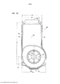
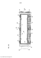
[055] A figura 40 é uma vista esquemática seccional transversal do conjunto de filtro de ar das figuras 32-39.[055] Figure 40 is a schematic cross-sectional view of the air filter assembly in figures 32-39.
[056] A figura 41 é uma vista esquemática seccional transversal tomada, no geral, ao longo da linha 41-41 da figura 40; Na figura 41, uma linha seccional transversal 40-40 indicando a vista da figura 40.[056] Figure 41 is a schematic cross-sectional view taken, in general, along line 41-41 of figure 40; In figure 41, a cross-sectional line 40-40 indicating the view in figure 40.
[057] A figura 42 é um vista elevada esquemática de extremidade fechada do cartucho de filtro usado no conjunto de filtro de ar das figuras 32-41.[057] Figure 42 is a schematic elevated view of the closed end of the filter cartridge used in the air filter assembly of figures 32-41.
[058] A figura 43 é uma vista elevada esquemática da extremidade aberta do cartucho da figura 42; a figura 43 ficando voltada para a direção de uma extremidade oposta àquela da figura 42.[058] Figure 43 is a schematic elevated view of the open end of the cartridge in Figure 42; figure 43 facing the direction of an opposite end to that of figure 42.
[059] A figura 44 é uma vista plana de topo esquemática do cartucho de filtro das figuras 42 e 43.[059] Figure 44 is a schematic top plan view of the filter cartridge in figures 42 and 43.
[060] A figura 45 é uma vista plana de base esquemática do cartucho de filtro das figuras 42-44.[060] Figure 45 is a schematic plan view of the filter cartridge in figures 42-44.
[061] A figura 46 é uma vista elevada lateral esquemática do cartucho de filtro das figuras 42-45.[061] Figure 46 is a schematic side elevation view of the filter cartridge in figures 42-45.
[062] A figura 47 é uma segunda vista elevada lateral esquemática do cartucho de filtro da figura 46, voltada para a direção de um lado oposto da vista da figura 46.[062] Figure 47 is a second schematic side elevation view of the filter cartridge of figure 46, facing away from the side of the view in figure 46.
[063] A figura 48A é uma vista esquemática seccional transversal do cartucho de filtro representado nas figuras 42-47.[063] Figure 48A is a schematic cross-sectional view of the filter cartridge shown in figures 42-47.
[064] A figura 48B é um vista fragmentária esquemática ampliada de uma parte selecionada da figura 48A.[064] Figure 48B is an enlarged schematic fragmentary view of a selected part of Figure 48A.
[065] A figura 49 é uma vista esquemática seccional transversal tomada, no geral, ao longo da linha 49-49, da figura 48.[065] Figure 49 is a schematic cross-sectional view taken, in general, along line 49-49, of figure 48.
[066] A figura 50 é uma vista elevada esquemática da extremidade aberta do cartucho de filtro da figura 46, a linha 48A-48A indicando a vista seccional transversal da figura 48A.[066] Figure 50 is a schematic elevated view of the open end of the filter cartridge of figure 46,
[067] A figura 51 é uma vista em perspectiva de topo esquemática do cartucho de filtro das figuras 42-47; a figura 51 ficando voltada, no geral, para a direção de uma extremidade fechada do cartucho de filtro.[067] Figure 51 is a schematic top perspective view of the filter cartridge of figures 42-47; figure 51 facing, in general, towards the closed end of the filter cartridge.
[068] A figura 52 é uma vista em perspectiva de topo esquemática do cartucho de filtro da figura 51, a vista da figura 52 ficando voltada para a direção de uma extremidade de saída.[068] Figure 52 is a schematic top perspective view of the filter cartridge of figure 51, the view of figure 52 facing the direction of an outlet end.
[069] A figura 53 é uma vista fragmentária esquemática ampliada da parte selecionada da figura 52.[069] Figure 53 is an enlarged schematic fragmentary view of the selected part of figure 52.
[070] A figura 54 é um vista esquemática explodida do cartucho de filtro da figura 52; na figura 54, uma vista em perspectiva é provida, no geral, a partir da mesma orientação da figura 52.[070] Figure 54 is an exploded schematic view of the filter cartridge of Figure 52; in figure 54, a perspective view is provided, in general, from the same orientation as in figure 52.
[071] A figura 55 é uma vista elevada de extremidade esquemática de um invólucro componente da figura 54.[071] Figure 55 is a schematic end elevation of a component housing of Figure 54.
[072] A figura 56 é uma vista elevada lateral esquemática do invólucro componente da figura 55.[072] Figure 56 is a schematic side elevation view of the component housing of Figure 55.
[073] A figura 57 é uma vista em perspectiva esquemática de uma cobertura de extremidade da pré-forma componente da figura 54.[073] Figure 57 is a schematic perspective view of an end cover of the component preform of Figure 54.
[074] A figura 58 é uma vista em perspectiva esquemática interna da cobertura de extremidade componente da figura 57.[074] Figure 58 is a schematic internal perspective view of the component end cover of Figure 57.
[075] A figura 59 é uma vista plana esquemática externa da cobertura de extremidade componente da figura 57.[075] Figure 59 is a schematic external plan view of the component end cover of figure 57.
[076] A figura 60 é uma vista esquemática seccional transversal tomada, no geral, ao longo da linha 60-60 da figura 59.[076] Figure 60 is a schematic cross-sectional view taken, in general, along line 60-60 of figure 59.
[077] A figura 61 é uma vista em perspectiva esquemática de um anel de suporte de vedação componente da figura 54.[077] Figure 61 is a schematic perspective view of a component seal support ring of Figure 54.
[078] A figura 62 é uma vista plana esquemática do componente da figura 61.[078] Figure 62 is a schematic plan view of the component in Figure 61.
[079] A figura 63 é uma vista elevada lateral esquemática do componente da figura 62.[079] Figure 63 is a schematic side elevation view of the component of Figure 62.
[080] A figura 64 é uma vista em perspectiva esquemática de um cartucho de filtro de segurança secundário do conjunto de filtro de ar das figuras 32-39.[080] Figure 64 is a schematic perspective view of a secondary safety filter cartridge from the air filter assembly of figures 32-39.
[081] A figura 65 é uma vista elevada lateral do cartucho de filtro secundário da figura 64, com partes mostradas em seção transversal.[081] Figure 65 is a side elevation view of the secondary filter cartridge in Figure 64, with parts shown in cross section.
[082] Meio de filtro estriado pode ser usado para prover construções de filtro de fluido de uma variedade de maneiras. Uma maneira bem conhecida é aqui caracterizada como uma construção de filtro-z. Entende-se que, da forma aqui usada, o termo "construção de filtro-z" diz respeito a uma construção de filtro na qual estrias de filtro corrugadas, dobradas ou de outra maneira formadas individuais são usadas para definir conjuntos de estrias de filtro de entrada e de saída longitudinais, tipicamente, paralelos para fluxo de fluido através do meio; o fluido fluindo ao longo do comprimento das estrias entre extremidades de fluxo (ou faces de fluxo) de entrada e de saída opostas do meio. Alguns exemplos de meio de filtro-z são providos ou usados nas patentes US 5.820.646, 5.772.883, 5.902.364, 5.792.247, 5.895.574, 6.210.469, 6.190.432, 6.179.890, 6.235.195, Des. 399.944, Des. 428.128, Des. 396.098, Des. 398.046 e Des. 437.401; cada uma destas quinze referências citadas sendo aqui incorporada pela referência.[082] Striated filter media can be used to provide fluid filter constructions in a variety of ways. A well-known way is characterized here as a z-filter construction. It is understood that, as used herein, the term "z-filter construction" refers to a filter construction in which individual corrugated, folded, or otherwise formed filter streaks are used to define sets of filter strips of longitudinal inlet and outlet, typically parallel for fluid flow through the medium; the fluid flowing along the length of the grooves between flow ends (or flow faces) opposite inlet and outlet of the medium. Some examples of z-filter media are provided or used in US patents 5,820,646, 5,772,883, 5,902,364, 5,792,247, 5,895,574, 6,210,469, 6,190,432, 6,179,890, 6,235,195 , Des. 399,944, Des. 428.128, Des. 396,098, Des. 398,046 and Des. 437,401; each of these fifteen references cited being incorporated herein by reference.
[083] Um tipo de meio de filtro-z utiliza dois componentes de meio específicos unidos para formar a construção do meio. Os dois componentes são: (1) uma folha de meio estriada (algumas vezes corrugada); e (2) uma folha de meio de revestimento. Tipicamente, a folha de meio de revestimento é não corrugada, entretanto, ela pode ser corrugada, por exemplo, perpendicularmente à direção da estria, da forma descrita no pedido provisório US 60/543.804, depositado em 11 de fevereiro de 2004, e publicado como PCT WO 05/077487 em 25 de agosto de 2005, aqui incorporado pela referência.[083] One type of z-filter medium uses two specific medium components joined together to form the medium construction. The two components are: (1) a sheet of striated medium (sometimes corrugated); and (2) a sheet of coating medium. Typically, the coating medium sheet is non-corrugated, however, it can be corrugated, for example, perpendicular to the direction of the groove, as described in
[084] A folha de meio estriada (algumas vezes corrugada) e a folha de meio de revestimento, juntas, são usadas para definir meio com estrias de entrada e de saída paralelas. Em alguns casos, a folha estriada e a folha de revestimento são presas juntas e, então, são bobinadas para formar uma construção de meio de filtro-z. Tais arranjos são descritos, por exemplo, em US 6.235.195 e 6.179.890, cada um dos quais é aqui incorporado pela referência. Em certos outros arranjos, algumas seções ou tiras não bobinadas de meio estriado (algumas vezes corrugado) presas no meio de revestimento são empilhadas uma na outra para criar uma construção de filtro. Um exemplo disto é descrito na figura 11 do 5.820.646, aqui incorporado pela referência.[084] The striated medium sheet (sometimes corrugated) and the coating medium sheet together are used to define medium with parallel inlet and outlet grooves. In some cases, the ribbed sheet and the liner sheet are attached together and then are wound to form a z-filter media construction. Such arrangements are described, for example, in US 6,235,195 and 6,179,890, each of which is incorporated herein by reference. In certain other arrangements, some striated (sometimes corrugated) sections or strips stuck in the coating medium are stacked together to create a filter construction. An example of this is described in figure 11 of 5,820,646, incorporated here by reference.
[085] Aqui, tiras do material que compreende folha estriada presa na folha corrugada, que, então, é montado em pilhas para formar meios filtrantes, são algumas vezes referidas como "tiras revestidoras únicas". Entende-se que o termo "tira revestidora única" e variantes deste, diz respeito ao fato de que uma face, isto é, uma única face da folha estriada (algumas vezes corrugada), é revestida pela folha de revestimento, na tira.[085] Here, strips of material comprising striated sheet attached to the corrugated sheet, which are then assembled in piles to form filter media, are sometimes referred to as "single coating strips". It is understood that the term "single coating strip" and variants thereof, refers to the fact that a face, that is, a single face of the striated sheet (sometimes corrugated), is coated by the coating sheet, on the strip.
[086] Entende-se que o termo "corrugado", aqui usado para dizer respeito à estrutura no meio, diz respeito a uma estrutura de estria resultante da passagem do meio entre dois cilindros de corrugação, isto é, no interior de uma linha de contato ou mordedura entre dois cilindros, cada um dos quais tendo recursos de superfície apropriados para ocasionar um efeito de corruga- ção no meio resultante. Não entende-se que o termo "corrugação" diz respeito a estrias que são formadas pelas técnicas que não envolvem a passagem de meio para o interior de uma mordedura entre cilindros de corrugação. Entretanto, entende-se que o termo "corrugado" se aplica mesmo se o meio for adicionalmente modificado ou deformado depois da corrugação, por exemplo, pelas técnicas de dobramento descritas em PCT WO 04/007054, publicado em 22 de janeiro de 2004, aqui incorporado pela referência.[086] It is understood that the term "corrugated", used here to refer to the structure in the middle, refers to a striated structure resulting from the passage of the medium between two corrugation cylinders, that is, inside a line of contact or bite between two cylinders, each of which has appropriate surface resources to cause a corrugating effect on the resulting medium. The term "corrugation" is not understood to refer to stretch marks that are formed by techniques that do not involve the passage of medium into a bite between corrugation cylinders. However, it is understood that the term "corrugated" applies even if the medium is further modified or deformed after corrugation, for example, by the folding techniques described in PCT WO 04/007054, published on January 22, 2004, here incorporated by reference.
[087] Meio corrugado é uma forma específica de meio estriado. Meio estriado é meio que tem estrias individuais (por exemplo, formadas por corru- gação ou dobramento) que se estendem através de si.[087] Corrugated medium is a specific form of striated medium. Striated media is media that has individual streaks (for example, formed by corrugation or folding) that extend through you.
[088] Entende-se que o termo "construção de meio de filtro-z", e variantes deste, da forma aqui usada, sem mais, diz respeito a todo ou qualquer um de uma trama de meio corrugado ou de outra forma estriado preso no (revestindo) meio com vedação apropriada para permitir a definição de estrias ou faces de fluxo de entrada e de saída; ou um meio filtrante construído ou formado a partir de tal meio em uma rede tridimensional de estrias de entrada e de saída; e/ou um cartucho de filtro ou construção que inclui um meio filtrante como este.[088] It is understood that the term "construction of z-filter medium", and variants of it, as used herein, without further ado, refers to any or all of a corrugated or otherwise striated trap web in the (covering) medium with appropriate sealing to allow the definition of grooves or faces of inlet and outlet flow; or a filter medium constructed or formed from such medium in a three-dimensional network of inlet and outlet grooves; and / or a filter cartridge or construction that includes a filter medium like this.
[089] Na figura 1, é mostrado um exemplo do meio 1 usado no meio de filtro-z. O meio 1 é formado por uma folha estriada, neste caso corrugada, 3 e uma folha de revestimento 4. Uma construção tal como o meio 1 é aqui referido como um revestidor único ou tira revestidora única.[089] In figure 1, an example of medium 1 used in the z-filter medium is shown. Medium 1 is formed by a fluted sheet, in this case corrugated, 3 and a coating sheet 4. A construction such as medium 1 is referred to herein as a single coating or single coating strip.
[090] No geral, a folha corrugada 3 da figura 1 é de um tipo aqui ca-racterizado, no geral, com um padrão regular, curvo, de onda de estrias ou cor- rugações 7. Neste contexto, entende-se que o termo "padrão de onda" diz respeito a uma estria ou padrão corrugado de sulcos 7b e cumes 7a alternados. Neste contexto, entende-se que o termo "regular" diz respeito ao fato de que os pares de sulcos e cumes (7b, 7a) alternam, no geral, com as mesmas forma e tamanho de repetição da corrugação (ou estria) (Também, tipicamente, em uma configuração regular, cada sulco 7b é, substancialmente, o inverso de cada cume 7a.). Assim, entende-se que o termo "regular" indica que o padrão de corrugação (ou estria) compreende sulcos e cumes, com cada par (compreendendo um sulco e cume adjacentes) repetindo, sem modificação substancial no tamanho e forma das corrugações ao longo de pelo menos 70 % do comprimento das estrias. Neste contexto, o termo "substancial", diz respeito a uma modificação resultante de uma mudança no processo ou forma usados para criar a folha corrugada ou estriada, em oposição a menores variações provenientes do fato de que a folha de meio 3 é flexível. Em relação à caracterização de um padrão de repetição, não entende-se que, em qualquer dada construção de filtro, um número igual de cumes e sulcos está necessariamente presente. O meio 1 pode ser terminado, por exemplo, entre um par que compreende um cume e um sulco, ou parcialmente ao longo de um par que compreende um cume e um sulco (Por exemplo, na figura 1, o meio 1 representado em vista fragmentária tem oito cumes completos 7a e sete sulcos completos 7b.). Também, as extremidades de estria opostas (extremidades dos sulcos e cumes) podem variar de uma para a outra. Tais variações nas extremidades são des- consideradas nestas definições, a menos que especificamente declarado. Isto é, pretende-se que variações nas extremidades de estrias sejam cobertas pelas definições expostas.[090] In general, the
[091] No contexto da caracterização de um padrão de corrugações de onda “curvo”, entende-se que o termo "curvo" diz respeito a um padrão de corrugação que não é o resultado de uma forma dobrada ou enrugada provida no meio, mas, em vez disto, o ápice 7a de cada cume e a base 7b de cada sulco são formados ao longo de uma curva raiada. Um raio típico para tal meio de filtro-z será pelo menos 0,25 mm e, tipicamente, será não mais que 3 mm.[091] In the context of the characterization of a "curved" wave corrugation pattern, it is understood that the term "curved" refers to a corrugation pattern that is not the result of a folded or wrinkled shape provided in the middle, but instead, the apex 7a of each ridge and the base 7b of each groove are formed along a striped curve. A typical radius for such a z-filter medium will be at least 0.25 mm and will typically be no more than 3 mm.
[092] Uma característica adicional do padrão regular, curvo, em onda em particular representado na figura 1, para a folha corrugada 3, é que aproxi-madamente em um ponto médio 30 entre cada sulco e cada cume adjacente, ao longo da maior parte do comprimento das estrias 7, fica localizado uma região de transição onde a curvatura inverte. Por exemplo, visualizando lado posterior ou face 3a da figura 1, o sulco 7b é uma região côncava, e o cume 7a é uma região convexa. Certamente, quando visualizado na direção do lado frontal ou face 3b, o sulco 7b do lado 3a forma um cume; e o cume 7a da face 3a forma um sulco (Em alguns casos, a região 30 pode ser um segmento reto, em vez de um ponto, com curvatura invertida nas extremidades do segmento 30.).[092] An additional feature of the regular, curved, wave pattern in particular shown in Figure 1, for
[093] Uma característica da folha estriada em padrão de onda regular (neste caso corrugado) 3 em particular mostrada na figura 1, é que as cor- rugações individuais são, no geral, retas. Neste contexto, entende-se por "reto", que em pelo menos 70 %, tipicamente, pelo menos 80 %, do comprimento entre bordas 8 e 9, os cumes 7a e os sulcos 7b não mudam, substancialmente, em seção transversal. O termo "reto" em relação ao padrão de corrugação mostrado na figura 1, em parte, distingue o padrão das estrias cônicas do meio corrugado descrito na figura 1 de WO 97/40918 e da Publicação PCT WO 03/47722, publicados em 12 de junho de 2003, aqui incorporado pela referência. Por exemplo, as estrias cônicas da figura 1 de WO 97/40918 serão um padrão de onda curvo, mas não um padrão “regular”, ou um padrão de estrias retas, da forma que os termos são aqui usados.[093] A characteristic of the striated sheet in a regular wave pattern (in this case corrugated) 3 in particular shown in figure 1, is that the individual corrugations are, in general, straight. In this context, "straight" is understood to mean that in at least 70%, typically at least 80%, of the length between
[094] Em relação à presente figura 1, e como exposto, o meio 1 tem primeira e segunda bordas opostas 8 e 9. Quando o meio 1 for formado em um meio filtrante, no geral, a borda 9 formará uma extremidade de entrada para o meio filtrante, e a borda 8 uma extremidade de saída, embora uma orientação oposta seja possível.[094] In relation to the present figure 1, and as explained, the medium 1 has first and second
[095] A borda adjacente 8 é provida com um filete de vedação 10, que veda a folha corrugada 3 e a folha de revestimento 4 juntas. Algumas vezes, o filete 10 será referido como um filete "revestidor único", já que ele é um filete entre a folha corrugada 3 e folha de revestimento 4, que forma o revesti- dor único ou tira de meio 1. O filete de vedação 10 veda a borda adjacente 8 das estrias individuais fechadas 11 em relação à passagem de ar a partir dali.[095] The
[096] A borda adjacente 9 é provida com um filete de vedação 14. No geral, o filete de vedação 14 fecha as estrias 15 em relação à passagem de fluido não filtrado para a borda adjacente 9. Tipicamente, o filete 14 será aplicado à medida que as tiras do meio 1 são presas uma na outra durante o empilhamento. Assim, o filete 14 formará uma vedação entre um lado posterior 17 da folha de revestimento 4 e o lado 18 da próxima folha corrugada adjacente 3. Quando o meio 1 for cortado em tiras e empilhado, em vez de bobinado, o filete 14 é referenciado como um "filete de empilhamento" (Quando o filete 14 for usado em um arranjo bobinado formado pelo meio 1, não aqui representado, ele é referenciado como um "filete de enrolamento").[096] The
[097] Em 20 da figura 1, é mostrado filete de adesão entre a folha estriada 3 e a folha de revestimento 4.[097] In 20 of figure 1, adhesion thread is shown between the
[098] Em relação à figura 1, uma vez que o meio 1 é incorporado em um meio filtrante, por exemplo, por empilhamento, ele pode ser operado como segue. Primeiro, ar na direção das setas 12 entrará nas estrias abertas 11 da extremidade adjacente 9. Em função do confinamento na extremidade 8, pelo filete 10, o ar passará através do meio, por exemplo, da forma mostrada pelas setas 13. Então, ele pode sair do meio filtrante, pela passagem através das extremidades abertas 15a das estrias 15, até a extremidade adjacente 8 do meio filtrante. Certamente, a operação pode ser conduzida com fluxo de ar na direção oposta.[098] In relation to figure 1, since the medium 1 is incorporated in a filter medium, for example, by stacking, it can be operated as follows. First, air in the direction of the
[099] Aqui, algumas vezes, um meio filtrante que compreende o meio 1 será referido com uma construção de fluxo “direto”, já que o ar a ser filtrado entra e sai do meio filtrante por meio das faces de fluxo opostas.[099] Here, sometimes, a filter medium comprising medium 1 will be referred to as a "direct" flow construction, since the air to be filtered enters and leaves the filter medium through the opposite flow faces.
[0100] Para o arranjo em particular aqui mostrado na figura 1, as cor- rugações paralelas 7a, 7b são, no geral, completamente retas através do meio, da borda 8 até a borda 9. Estrias ou corrugações retas podem ser deformadas ou dobradas em locais selecionados, especialmente, nas extremidades. Modificações nas extremidades de estria para confinamento são, no geral, desconsideradas nas definições expostas de "regular", "curvo" e "padrão de onda".[0100] For the particular arrangement shown here in figure 1, the parallel corrugations 7a, 7b are, in general, completely straight through the middle, from
[0101] Construções de filtro-z que não utilizam formas de corrugação retas em padrão de onda curvo regular são conhecidas. Por exemplo, em US 5.562.825 de Yamada et al., são mostrados padrões de corrugação que utilizam estrias de entrada um tanto semicirculares (em seção transversal) adjacentes às estrias de saída estreitas em forma de V (com lados curvos) (veja figuras 1 e 3, de 5.562.825). Em US 5.049.326 de Matsumoto et al., são mos- tradas estrias circulares ou tubulares (em seção transversal) definidas por uma folha com meios tubos anexados em uma outra folha com meios tubos, com regiões chatas entre as estrias retas paralelas resultantes, veja figura 2 da '326 de Matsumoto. Em US 4.925.561 de Ishii, et al. (figura 1), são mostradas estrias dobradas para ter uma seção transversal retangular, em que as estrias afunilam ao longo de seus comprimentos. Em WO 97/40918 (figura 1), são mostradas estrias ou corrugações paralelas que têm padrões de onda curvos (dos sulcos convexo e côncavo curvos adjacentes), mas que afunilam ao longo de seus comprimentos (e, assim, não são retas). Também, em WO 97/40918, são mostradas estrias que têm padrões de onda curvos, mas com cumes e sulcos de diferente tamanhos.[0101] Z-filter constructions that do not use straight corrugated forms in a regular curved wave pattern are known. For example, in US 5,562,825 by Yamada et al., Corrugation patterns are shown that use somewhat semicircular inlet grooves (in cross section) adjacent to the narrow V-shaped outlet grooves (with curved sides) (see figures 1 and 3, of 5,562,825). In US 5,049,326 by Matsumoto et al., Circular or tubular grooves (in cross section) are shown, defined by a sheet with half tubes attached to another sheet with half tubes, with flat regions between the resulting parallel straight grooves. see figure 2 of Matsumoto's' 326. In US 4,925,561 to Ishii, et al. (figure 1), ribs are shown folded to have a rectangular cross section, in which the ribs taper along their lengths. In WO 97/40918 (figure 1), parallel streaks or corrugations are shown that have curved wave patterns (from adjacent curved convex and concave grooves), but that taper along their lengths (and thus are not straight). Also, in WO 97/40918, streaks are shown that have curved wave patterns, but with ridges and grooves of different sizes.
[0102] No geral, o meio de filtro é um material relativamente flexível, tipicamente, um material fibroso não tecido (de fibras de celulose, fibras sintéticas ou ambas) que, frequentemente, inclui uma resina, algumas vezes, tratado com materiais adicionais. Assim, ele pode ser conformado ou configurado nos vários padrões corrugados, sem dano inaceitável do meio. Também, ele pode ser prontamente bobinado ou de outra forma configurado para uso, novamente, sem dano inaceitável do meio. Certamente, ele deve ser de uma natureza tal que mantenha a configuração corrugada exigida durante o uso.[0102] In general, the filter medium is a relatively flexible material, typically a fibrous non-woven material (cellulose fibers, synthetic fibers or both) that often includes a resin, sometimes treated with additional materials. Thus, it can be conformed or configured in the various corrugated patterns, without unacceptable damage to the medium. Also, it can be readily wound or otherwise configured for use, again, without unacceptable damage to the medium. Certainly, it must be of a nature that maintains the corrugated configuration required during use.
[0103] No processo de corrugação, uma deformação inelástica é ocasionada no meio. Isto impede que o meio retorne para sua forma original. Entretanto, uma vez que a tensão é liberada, a estria ou as corrugações tenderão a saltar para fora, recuperando somente uma parte do estiramento e curvando aquele que ocorreu. Algumas vezes, a folha de meio de revestimento é pregada na folha de meio estriada para inibir este salto para fora da folha corrugada. Tal pregagem é mostrada em 20.[0103] In the corrugation process, an inelastic deformation is caused in the middle. This prevents the medium from returning to its original form. However, once the tension is released, the streak or corrugations will tend to bounce outward, recovering only part of the stretch and curving the one that occurred. Sometimes, the coating medium sheet is nailed to the ribbed medium sheet to inhibit this leap out of the corrugated sheet. Such nailing is shown in 20.
[0104] Também, tipicamente, o meio contém uma resina. Durante o processo de corrugação, o meio pode ser aquecido até acima o ponto de transição vítrea da resina. Então, quando a resina resfria, isto ajuda a manter as formas estriadas.[0104] Also, typically, the medium contains a resin. During the corrugation process, the medium can be heated up to the glass transition point of the resin. So, when the resin cools, it helps to keep the striated shapes.
[0105] O meio da folha corrugada 3, da folha de revestimento 4 ou de ambas, pode ser provido com um fino material de fibra em um ou ambos os lados destes, por exemplo, de acordo com US 6.673.136, aqui incorporado pela referência. Em alguns casos, quando tal fino material de fibra for usado, pode ser desejável prover a fina fibra no lado à montante do material e no interior das estrias. Quando isto ocorre, tipicamente, o fluxo do ar durante a filtragem ficará no interior da borda que compreende o filete de empilhamento.[0105] The medium of the
[0106] Um problema em relação às construções de filtro-z diz respeito a confinamento das extremidades de estria individuais. Embora alternativas sejam possíveis, tipicamente, um selante ou adesivo é provido para realizar o confinamento. Como fica aparente a partir da discussão exposta, no meio de filtro-z típico, especialmente aquele que usa estrias retas em oposição às estrias cônicas e selante para vedar as estrias, grandes áreas de superfície (e volume) de selante tanto na extremidade à montante quanto na extremidade à jusante são necessárias. Vedações de alta qualidade nestes locais são críticas para a operação apropriada da estrutura do meio que resulta. Os altos volume e área de selante criam problemas em relação a isto.[0106] One problem with the z-filter constructions concerns the confinement of the individual spline ends. Although alternatives are possible, typically a sealant or adhesive is provided to carry out the containment. As is apparent from the discussion above, in the typical z-filter medium, especially one that uses straight grooves as opposed to conical grooves and sealant to seal the grooves, large surface areas (and volume) of sealant both at the upstream end as at the downstream end they are necessary. High quality seals in these locations are critical for the proper operation of the resulting media structure. The high volume and area of sealant create problems in this regard.
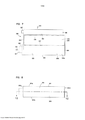
[0107] Atenção é agora direcionada para a figura 2, na qual é es-quematicamente representada uma construção de meio de filtro-z 40 que utiliza uma folha corrugada com padrão regular, curvo, em onda 43 e uma folha chata não corrugada 44, isto é, uma tira revestidora única. A distância D1, entre os pontos 50 e 51, define a extensão do meio chato 44 na região 52 subjacente a uma dada estria corrugada 53. O comprimento D2 do meio arqueado para a estria corrugada 53, na mesma distância D1 é, certamente, maior que D1, em função da forma da estria corrugada 53. Para um meio de forma regular típico usado em aplicações de filtro estriado, o comprimento linear D2 do meio 53 entre os pontos 50 e 51 será, frequentemente, pelo menos 1,2 vez D1. Tipicamente, D2 estará na faixa de 1,2 - 2,0 vezes D1, inclusive. Um arranjo particularmente conveniente para filtros de ar tem uma configuração na qual D2 é de cerca de 1,25 - 1,35 x D1. Por exemplo, tal meio foi comercialmente usado em arranjos de filtro-z Donaldson PowercoreTM. Um outro tamanho potencialmente conveniente será um no qual D2 é cerca de 1,4 - 1,6 vez Di. Aqui, o razão D2 / D1 será, algumas vezes, caracterizada como razão estria / plano ou meio esticado pelo meio corrugado.[0107] Attention is now directed to figure 2, in which a construction of z-
[0108] Na indústria de papelão corrugado, vários padrões de estrias foram definidos. Por exemplo, estria padrão E, estria padrão X, estria padrão B, estria padrão C e estria padrão A. A figura 3, anexa, em conjunto com a Tabela A, a seguir, provê definições destas estrias.[0108] In the corrugated cardboard industry, several streak patterns have been defined. For example, streak pattern E, streak pattern X, streak pattern B, streak pattern C and streak pattern A. Figure 3, attached, together with Table A, below, provides definitions of these streaks.
[0109] Donaldson Company, Inc., (DCI) o cessionário da presente divulgação, usou variações das estrias padrão A e padrão B em uma variedade de arranjos de filtro-z. Estas estrias também são definidas na Tabela A e na figura 3.

[0110] Certamente, outras definições de padrões de estrias da indústria de caixa corrugada são conhecidas.[0110] Certainly, other definitions of streak standards in the corrugated box industry are known.
[0111] No geral, configurações de padrão de estria da indústria de caixa corrugada podem ser usadas para definir formas de corrugação ou formas de corrugação aproximadas para o meio corrugado. Comparações expostas entre a estria DCI A e a estria DCI B e as estrias padrão A e padrão B da indústria de corrugação indicam algumas variações convenientes.[0111] In general, corrugated box industry streak pattern settings can be used to define forms of corrugation or approximate forms of corrugation for the corrugated medium. Comparisons exposed between the DCI A groove and the DCI B groove and the corrugation industry's Standard A and Standard B grooves indicate some convenient variations.
[0112] Definições de estria alternativas, tais como aquelas descritas nos pedidos provisórios US: 60/899.311, depositado em 2 de fevereiro de 2007; e 60/937.162, depositado em 26 de junho de 2007 podem ser utilizadas em arranjos de acordo com a presente divulgação. Cada um destes dois pedidos provisórios US é aqui incorporado pela referência.[0112] Alternative streak definitions, such as those described in provisional US orders: 60 / 899,311, filed on February 2, 2007; and 60 / 937,162, deposited on June 26, 2007 can be used in arrangements in accordance with the present disclosure. Each of these two provisional US orders is hereby incorporated by reference.
[0113] Na figura 4, é mostrado um exemplo de um processo de fabricação para fazer uma tira de meio correspondente à tira 1 da figura 1. No geral, a folha de revestimento 64 e a folha estriada (corrugada) 66 com estrias 68 são juntadas para formar uma trama do meio 69, com um filete adesivo localizado entre elas em 70. O filete adesivo 70 formará um filete revestidor único 14 da figura 1.[0113] In figure 4, an example of a manufacturing process for making a strip of medium corresponding to strip 1 of figure 1 is shown. In general, the
[0114] Entende-se que o termo "filete revestidor único" diz respeito a um filete de vedação posicionado entre camadas de um revestidor único, isto é, entre a folha estriada e a folha de revestimento.[0114] It is understood that the term "single coating film" refers to a sealing film positioned between layers of a single film coating, that is, between the striated sheet and the covering sheet.
[0115] Um processo de sutura opcional ocorre na estação 71, para formar seção suturada central 72 localizada no meio da trama. O meio de filtro- z ou a tira de meio-z 74 pode ser cortado ou fendido em 75, ao longo do filete 70, para criar duas peças 76, 77 de meio de filtro-z 74, cada uma das quais tendo uma borda com uma tira de selante (filete revestidor único) que se estende entre a corrugação e a folha de revestimento. Certamente, se o processo de sutura opcional for usado, a borda com uma tira de selante (filete revestidor único) também terá um conjunto de estrias suturadas neste local. Então, as tiras ou peças 76, 77 podem ser cortadas em tiras revestidoras únicas para empilhamento, da forma descrita a seguir em relação à figura 6.[0115] An optional suturing process takes place at station 71, to form a central sutured section 72 located in the middle of the weft. The z-filter medium or the z-strip strip 74 can be cut or slit at 75, along the
[0116] Técnicas para conduzir um processo caracterizado em relação à figura 4 são descritas em PCT WO 04/007054, publicado em 22 de janeiro de 2004, aqui incorporado pela referência.[0116] Techniques for conducting a process characterized in relation to figure 4 are described in PCT WO 04/007054, published on January 22, 2004, incorporated herein by reference.
[0117] Ainda em relação à figura 4, antes de o meio de filtro-z 74 ser colocado através da estação de sutura 71, o meio 74 deve ser formado. Na representação esquemática mostrada na figura 4, isto é feito pela passagem de uma folha de meio chata 92 através de um par de cilindros de corrugação 94, 95. Na representação esquemática mostrada na figura 4, a folha de meio chata 92 é desenrolada de um rolo 96, enrolada ao redor dos cilindros de tensão 98 e, então, passada através de uma linha de contato ou mordedura 102 entre os cilindros de corrugação 94, 95. Os cilindros de corrugação 94, 95 têm dentes 104 que darão a forma geral desejada das corrugações depois de a folha chata 92 passar através da linha de contato 102. Depois de passar através da linha de contato 102, a folha chata 92 fica corrugada, e é referenciada em 66 como a folha corrugada. Então, a folha de meio corrugada (isto é, estriada) 66 é presa na folha do meio de revestimento 64 (O processo de corrugação pode envolver aquecer o meio, em alguns casos.).[0117] Still in relation to figure 4, before the z-filter medium 74 is placed through the suture station 71, the medium 74 must be formed. In the schematic representation shown in figure 4, this is done by passing a flat sheet 92 through a pair of corrugation cylinders 94, 95. In the schematic representation shown in figure 4, the flat sheet 92 is unrolled from one roller 96, wrapped around tension rollers 98 and then passed through a contact or
[0118] Ainda em relação à figura 4, o processo também mostra a folha de revestimento 64 sendo roteada até o processo da estação de sutura 71. A folha de revestimento 64 é representada armazenada em um rolo 106 e, então, direcionada até a folha corrugada 66, para formar o meio-z 74. A folha corrugada 66 e a folha de revestimento 64 são presas juntas pelo adesivo ou por outro meio (por exemplo, por solda sônica).[0118] Still in relation to figure 4, the process also shows the
[0119] Em relação à figura 4, uma linha adesiva 70 é mostrada usada para prender a folha corrugada 66 e a folha de revestimento 64 juntas, co mo o filete de vedação. Alternativamente, o filete de vedação para formar o filete de revestimento pode ser aplicado da forma mostrada em 70a. Se o selante for aplicado em 70a, pode ser desejável colocar uma folga no cilindro de corru- gação 95 e, possivelmente, em ambos os cilindros de corrugação 94, 95, para acomodar o filete 70a.[0119] With reference to figure 4, an
[0120] O tipo de corrugação provida no meio corrugado é uma questão de escolha, e será indicado pela corrugação ou dentes de corrugação dos cilindros de corrugação 94, 95. Um tipo típico de estria padrão será um corru- gação com padrão de onda regular tipicamente curvo, de estrias retas, da forma aqui definida anteriormente. Um típico padrão de onda curva regular usado será um no qual a distância D2, supradefinida, em um padrão corrugado é pelo menos 1,2 vezes a distância D1 supradefinida. Em uma aplicação típica, tipicamente, D2 = 1,25 - 1,35 x D1; em uma outra, D2 = 1,4 - 1,6 x D1. Em alguns casos as técnicas podem ser aplicadas com padrões de onda curvos que não são "regulares", incluindo, por exemplo, aqueles que não usam estrias retas.[0120] The type of corrugation provided in the corrugated medium is a matter of choice, and will be indicated by the corrugation or corrugation teeth of the corrugation cylinders 94, 95. A typical type of standard groove will be a corrugation with a regular wave pattern typically curved, with straight grooves, as previously defined. A typical regular curved wave pattern used will be one in which the distance D2, suprefined, in a corrugated pattern is at least 1.2 times the distance D1 suprefined. In a typical application, typically, D2 = 1.25 - 1.35 x D1; in another, D2 = 1.4 - 1.6 x D1. In some cases the techniques can be applied with curved wave patterns that are not "regular", including, for example, those that do not use straight streaks.
[0121] Como descrito, o processo mostrado na figura 4 pode ser usado para criar a seção suturada central 72. A figura 5 mostra, em seção transversal, uma das estrias 68 depois da sutura e do fendimento.[0121] As described, the process shown in figure 4 can be used to create the central sutured section 72. Figure 5 shows, in cross section, one of the grooves 68 after suture and fissure.
[0122] Um arranjo de dobra 118 pode ser visto formando uma estria suturada 120 com quatro rugas 121a, 121b, 121c, 121d. O arranjo de dobra 118 inclui uma primeira camada ou parte chata 122 que é presa na folha de revestimento 64. Uma segunda camada ou parte 124 é mostrada pressionada contra a primeira camada ou parte 122. Preferivelmente, a segunda camada ou parte 124 é formada pelo dobramento de extremidades externas opostas 126, 127 da primeira camada ou parte 122.[0122] A
[0123] Ainda em relação à figura 5, no geral, duas das dobras ou ru- gas 121a, 121b serão aqui referidas como dobras ou rugas “superiores, direcionadas para dentro”. Neste contexto, entende-se que o termo "superior" indica que as rugas ficam em uma parte superior da íntegra da dobra 120, quando a dobra 120 for visualizada na orientação da figura 5. Entende-se que o termo "direcionado para dentro" diz respeito ao fato de que a linha da dobra ou linha da ruga de cada ruga 121a, 121b são voltadas uma para a direção da outra.[0123] Still in relation to figure 5, in general, two of the folds or
[0124] Na figura 5, no geral, as rugas 121c, 121d serão aqui referidas como rugas “inferiores, direcionadas para fora”. Neste contexto, o termo "inferior" diz respeito ao fato de que as rugas 121c, 121d não estão localizadas no topo, como estão as rugas 121a, 121b, na orientação da figura 5. Entende- se que o termo "direcionado para fora" indica que as linhas de dobra das rugas 121c, 121d são direcionadas uma para longe da outra.[0124] In figure 5, in general,
[0125] Entende-se que os termos "superior" e "inferior", da forma usada neste contexto, dizem respeito, especificamente, à dobra 120, quando visualizada a partir da orientação da figura 5. Isto é, não entende-se que eles sejam de outra forma indicativos da direção, quando a dobra 120 for orientada em um produto real para uso.[0125] It is understood that the terms "upper" and "lower", as used in this context, specifically refer to fold 120, when viewed from the orientation of figure 5. That is, it is not understood that they are otherwise indicative of the direction when
[0126] Com base nestas caracterizações e revisão da figura 5, pode- se ver que um arranjo de dobra regular exemplar 118, de acordo com a figura 5 desta divulgação, é um que inclui pelo menos duas "rugas superiores, direcionadas para dentro". Estas rugas direcionadas para dentro são exclusivas e ajudam a prover um arranjo geral no qual a dobramento não ocasiona uma significativa intrusão nas estrias adjacentes.[0126] Based on these characterizations and revision of figure 5, it can be seen that an exemplary
[0127] Uma terceira camada ou parte 128 também pode ser vista pressionada contra a segunda camada ou parte 124. A terceira camada ou parte 128 é formada peo dobramento das extremidades internas opostas 130, 131 da terceira camada 128.[0127] A third layer or
[0128] Uma outra maneira de visualizar o arranjo de dobra 118 é em relação à geometria dos cumes e sulcos alternados da folha corrugada 66. A primeira camada ou parte 122 é formada por um cume invertido. A segunda camada ou parte 124 corresponde a um pico duplo (depois da inversão do cume) que é dobrado na direção do cume invertido e, em arranjos preferidos, dobrado contra ele.[0128] Another way of visualizing the
[0129] Técnicas para prover a sutura opcional descrita em conjunto com a figura 5 de uma maneira preferida são descritas em PCT WO 04/007054, aqui incorporado pela referência. Percebe-se que uma variedade de fechamentos de extremidade dobrada alternativos nas estrias pode ser usada.[0129] Techniques for providing the optional suture described together with figure 5 in a preferred manner are described in PCT WO 04/007054, incorporated herein by reference. It is realized that a variety of alternative folded-end closures on the grooves can be used.
[0130] Técnicas aqui descritas são bem adaptadas para o uso dos meios filtrantes que resultam dos arranjos que, em vez de ser formados por bobinamento, são formados a partir de uma pluralidade de tiras do revestidor único.[0130] Techniques described here are well adapted for the use of filter media that result from arrangements that, instead of being formed by winding, are formed from a plurality of strips of the single coat.
[0131] Extremidades de fluxo ou faces de fluxo opostas do meio filtrante podem ser providas com uma variedade de diferentes definições. Em muitos arranjos, no geral, as extremidades são chatas e perpendiculares uma em relação à outra.[0131] Flow ends or opposite flow faces of the filter medium can be provided with a variety of different definitions. In many arrangements, in general, the ends are flat and perpendicular to each other.
[0132] As vedações da estria (filete revestidor único, filete de enrolamento ou filete de empilhamento) podem ser formadas a partir de uma variedade de materiais. Em várias das referências citadas e incorporadas, vedações de fusão a quente ou de poliuretano são descritas como possíveis para várias aplicações. Estas são usadas para as aplicações aqui descritas.[0132] The groove seals (single coating thread, winding thread or stacking thread) can be formed from a variety of materials. In several of the cited and incorporated references, hot melt or polyurethane seals are described as possible for various applications. These are used for the applications described here.
[0133] Na figura 6, é esquematicamente mostrada uma etapa de formar um meio filtrante de filtro-z empilhado a partir das tiras de meio de filtro- z, cada tira sendo uma folha estriada presa em uma folha de revestimento. Em relação à figura 6, a tira revestidora única 200 está sendo mostrada adicionada em uma pilha 201 de tiras 202 análogas à tira 200. A tira 200 pode ser cortada a partir de ambas as tiras 76, 77 da figura 4. Em 205, figura 6, é mostrada a aplicação de um filete de empilhamento 206 entre cada camada correspondente a uma tira 200, 202 em uma borda oposta do filete revestidor único ou da vedação (Empilhamento também pode ser feito com cada camada sendo adicionada na base da pilha, em oposição ao topo.).[0133] In figure 6, a step is shown schematically of forming a z-filter media stacked from the z-filter media strips, each strip being a striated sheet attached to a covering sheet. With reference to figure 6, the
[0134] Em relação à figura 6, cada tira 200, 202 tem bordas frontal e posterior 207, 208 e bordas laterais opostas 209a, 209b. No geral, estrias de entrada e de saída da combinação de folha corrugada / folha de revestimento que compreende cada tira 200, 202 se estendem entre as bordas frontal e posterior 207, 208, e paralelas às bordas laterais 209a, 209b.[0134] With reference to figure 6, each
[0135] Ainda em relação à figura 6, no meio filtrante 201 que está sendo formado, faces de fluxo opostas são indicadas em 210, 211. A seleção de qual das faces 210, 211 é a face de extremidade de entrada e qual é a face de extremidade de saída durante a filtragem é uma questão de escolha. Em alguns casos, o filete de empilhamento 206 é posicionado adjacente à face à montante ou de entrada 211; em outros, o oposto é verdadeiro. As faces de fluxo 210, 211 se estendem em entre faces laterais opostas 220, 221.[0135] Still in relation to figure 6, in the
[0136] Algumas vezes, o meio filtrante empilhado 201, mostrado sendo formado na figura 6, é aqui referido como um meio filtrante empilhado "em bloco". Neste contexto, o termo "em bloco" é uma indicação de que o arranjo é formado em um bloco retangular no qual todos as faces ficam em 90 ° em relação a todas as faces de parede unidas. Configurações alternativas são possíveis. Por exemplo, em alguns casos a pilha pode ser criada com cada tira 200 sendo ligeiramente deslocada do alinhamento com uma tira adjacente, para criar uma forma de bloco paralelogramo ou inclinado, com a face de entrada e a face de saída paralelas uma em relação à outra, mas não perpendicular às superfícies superior e de base.[0136] Sometimes the
[0137] Em alguns casos, o meio filtrante 201 será referenciado com uma forma de paralelogramo em qualquer seção transversal, significando que quaisquer duas faces laterais opostas se estendem, no geral, paralelas uma em relação à outra.[0137] In some cases, filter
[0138] Percebe-se que um arranjo empilhado em bloco correspondente à figura 6 é descrito na tecnologia anterior da US 5.820.646, aqui incorporada pela referência. Também percebe-se que arranjos empilhados são descritos na US 5.772.883; 5.792.247; US PCT WO 04/071616, publicado em 26 de agosto de 2004; e US 7.282.075. Cada uma destas quatro últimas referências é aqui incorporada pela referência em suas íntegras. Percebe-se que o arranjo empilhado mostrado em US 7.282.075 é um arranjo empilhado inclinado.[0138] It is noticed that an arrangement stacked in block corresponding to figure 6 is described in the previous technology of US 5,820,646, incorporated herein by reference. It is also noted that stacked arrangements are described in US 5,772,883; 5,792,247; US PCT WO 04/071616, published on August 26, 2004; and US 7,282,075. Each of these last four references is hereby incorporated by the reference in its entirety. It is realized that the stacked arrangement shown in US 7,282,075 is an inclined stacked arrangement.
[0139] Aqui, nas figuras 7-21, um primeiro conjunto de filtro de ar e componentes exemplares descritos aqui e em US 61/003.215 são representados esquematicamente. Em relação à figura 7, o conjunto de filtro de ar 300 é representado em vista lateral elevada. O conjunto de filtro de ar 300 inclui alojamento 301 com um lado de entrada 302 e extremidade de saída 303.[0139] Here, in figures 7-21, a first set of air filter and exemplary components described here and in US 61 / 003.215 are represented schematically. In relation to figure 7, the
[0140] O arranjo pré-filtro 306 fica posicionado sobre o lado de en- trada 302. Por exemplo, o pré-filtro 306 pode incluir uma pluralidade de tubos pré-separadores, tais como tubos separadores ciclônicos, não representados na figura 7. Tipicamente, um pré-filtro como este terá uma saída do fluxo de poeira, que permite tanto a remoção por gravidade da poeira separada pelo pré-filtro 306 quanto a anexação de uma mangueira de descontaminação. Uma saída 307 para uma mangueira de descontaminação é indicada em um local opcional.[0140] The
[0141] No geral, ar a ser filtrado passa para o interior do conjunto de filtro de ar 301 pela primeira passagem para o interior (opcional) do pré-filtro 306, na direção da seta 310. Depois da passagem através do pré-filtro 306, o ar entra no alojamento de filtro de ar 301, através do lado de entrada 302. No alojamento 301, é posicionado um cartucho de filtro de ar que inclui um meio filtrante que compreende uma pilha de tiras de filtro-z, no geral, de acordo com descrições prévias. Isto é, tipicamente, cada tira compreenderá uma folha estriada presa em uma folha de revestimento, com as tiras arranjadas em uma pilha com vedação apropriada para garantir que o ar que passa para o interior de uma face de fluxo passe através do meio antes de ele passar através da face de fluxo oposta. Princípios discutidos acima em conjunto com as figuras 16 podem ser usados para isto.[0141] In general, air to be filtered passes into the
[0142] Em relação à figura 7, um meio filtrante de filtro-z 315 é representado esquematicamente em linhas tracejadas posicionadas, no geral, da forma orientada no interior do alojamento 301. O meio filtrante 315 tem uma face de fluxo de entrada 316 e uma face de fluxo de saída oposto 317. O meio filtrante 315 tem primeiro lado e lado oposto 318, 319 que se estendem entre as faces de fluxo 316, 317. Então, o meio filtrante 315 pode compreender uma pilha de tiras do meio de filtro-z, com estrias se estendendo em uma direção entre a face de fluxo de entrada 316 e a face de fluxo de saída 317. Então, à medida que o ar sai da face de fluxo 317, ele terá sido filtrado pelo meio filtrante de filtro-z 315.[0142] With reference to figure 7, a z-
[0143] Depois de sair do meio filtrante 315, o ar filtrado entra em uma parte da região de ar limpo 320 e, consequentemente, deixa o alojamento de filtro 301 por meio de um arranjo de saída do alojamento de filtro de ar ou saída 321, na extremidade de saída 303. Em alguns casos, um elemento de segurança opcional ou elemento secundário é provido na região 320, através da qual o ar deve passar antes de ele sair pela saída 321. Ar filtrado que sai pela saída 321 é indicado, no geral, pela seta 311.[0143] After leaving the
[0144] Novamente, a figura 7 é, no geral, esquemática. Pretende-se que a figura proporcione um entendimento geral de uma orientação de um arranjo de acordo com a presente divulgação.[0144] Again, figure 7 is, in general, schematic. It is intended that the figure provides a general understanding of an orientation of an arrangement in accordance with the present disclosure.
[0145] Como ficará aparente a partir das discussões a seguir, o meio filtrante 315 é preso de forma não removível em um alojamento do cartucho de filtro, discutido a seguir. O cartucho de filtro de ar, que compreende a combinação do meio filtrante 315 e de um alojamento do cartucho de filtro de ar, é uma parte de manutenção, posicionada em um interior 301i do alojamento de filtro de ar 301.[0145] As will be apparent from the discussions below, the
[0146] Percebe-se que o filtro de ar 300 é representado, na figura 7, em uma orientação vertical, com o lado de entrada 302 direcionado para cima. Um filtro de ar que usa princípios análogos pode ser diferente, por exemplo, ele pode ser orientado com uma extremidade de entrada 302 voltada para a direção de um lado em vez de para cima. Orientações alternativas para o conjunto 300 podem ser beneficiadas por locais alternativos para a saída da poeira pela saída 307 do pré-filtro opcional 306.[0146] It is noticed that the
[0147] Atenção é direcionada para a figura 8, uma vista esquemática plana de base tomada, no geral, na direção da extremidade 312 do alojamento 301, figura 7. A figura 8 é provida, em parte, para orientar a vista seccional transversal da figura 12, discutida a seguir. Em relação à figura 8, o alojamento 301 pode ser visto com primeiro e segundo lados opostos 301a, 301b, e primeira e segunda extremidades opostas 301c, 301d. Como ficará aparente a partir das discussões a seguir, o lado 301d compreende uma cobertura de acesso removível, para acesso de manutenção ao interior 301i do alojamento 301.[0147] Attention is directed to figure 8, a schematic plan view of the base taken, in general, towards the
[0148] Agora, a atenção é direcionada para a figura 9. A figura 9 é um vista elevada da extremidade de saída tomada, no geral, na direção da extremidade de saída 303, figura 7. Em relação à figura 9, a saída do filtro de ar 303 é visualizável. Também é visualizável o pré-filtro 306 posicionado sobre a entrada 302 do alojamento 301. O meio filtrante internamente posicionado 315, com a face de fluxo de entrada 316 e a face de fluxo de saída oposta 317, é representado em linhas tracejadas.[0148] Now, attention is directed to figure 9. Figure 9 is an elevated view of the outlet end taken, in general, towards the
[0149] Ainda em relação à figura 9, pode-se ver que o alojamento de filtro de ar exemplar 301 inclui, no geral, primeira e segunda seções laterais opostas 301a, 301b, com as partes 321, 322, respectivamente, se estendendo, no geral, paralelas uma em relação à outra, na extensão da face de entrada 302 na direção de uma extremidade do alojamento de filtro de ar 312 oposta à face de entrada 302. Para o alojamento exemplar em particular 301 representado, a extremidade 312 é uma extremidade curva 325 e tem uma dimensão maior D1, através de si, do que uma distância D2 entre seções laterais opostas 321, 322. No exemplo mostrado, a extremidade curva 325 é posicionada com a seção lateral 322 que encaixa na região curva 325, no geral, tangencialmente. Entretanto, no exemplo representado, a seção lateral 321 não encaixa na ex- tremidade curva 325 tangencialmente.[0149] Still in relation to figure 9, it can be seen that the exemplary
[0150] Em relação à figura 9, entende-se que a região de ar limpo 320 fica posicionada, no geral, na região curva fechada 325 do alojamento 301.[0150] In relation to figure 9, it is understood that the region of
[0151] Agora, a atenção é direcionada para a figura 10. Na figura 10, é provida uma vista elevada lateral tomada, no geral, na direção do lado 301d, figura 8. Assim, a vista lateral da figura 10 é um lado ou extremidade oposta 301d da extremidade 301c, visualizável na figura 9. No geral, a extremidade 301d visualizável na figura 10 é referida como uma extremidade de acesso 330. A extremidade de acesso 330 inclui uma cobertura de acesso ao alojamento de filtro de ar removível 331 presa sobre ele. Um método exemplar de prisão da cobertura de acesso será o uso de trincos, indicado esquematicamente em 333. Uma abordagem alternativa usada para prisão é discutida a seguir em conjunto com a modalidade das figuras 22-31.[0151] Now, attention is directed to figure 10. In figure 10, an elevated side view is provided, in general, in the direction of
[0152] Em 335, é representada uma região de projeção na cobertura de acesso 331, na direção do visualizador. Um lado de projeção oposto 335 compreende uma região receptora ou recesso de cabo, para recepção de uma parte de cabo opcional de um cartucho de filtro que pode passar por manutenção, conforme discutido a seguir.[0152] In 335, a projection region is represented in the
[0153] Na figura 11, um vista plana de topo do conjunto de filtro de ar 300 é representada. A vista da figura 11 é tomada, no geral, na direção do pré- filtro 306. Tubos separadores ciclônicos individuais 338 são esquematicamente representados. Em operação, à medida que o ar entra nos tubos ciclônicos 338 (figura 11), um padrão de fluxo ciclônico é gerado em cada um deles, com parte da poeira sendo separada e removida através da saída 307. Então, o ar restante é direcionado para o interior do alojamento de filtro de ar 301 para filtragem, pela passagem através do meio filtrante 315, conforme previamente refe- renciado.[0153] In figure 11, a top plan view of the
[0154] Recursos interiores do conjunto de filtro de ar 300 podem ser entendidos pela revisão da figura 12, uma vista seccional transversal tomada, no geral, ao longo da linha 12-12, figura 8.[0154] Interior features of the air filter set 300 can be understood by revising figure 12, a cross-sectional view taken, in general, along line 12-12, figure 8.
[0155] Em relação à figura 12, percebe-se que o pré-filtro 306 não é representado com tubos separadores 338, por conveniência. Tudo que é visua- lizável na figura 12 é o invólucro ou alojamento externos 306a do pré-filtro 306.[0155] In relation to figure 12, it is noticed that the pre-filter 306 is not represented with
[0156] Ainda em relação à figura 12, a cobertura de acesso 331 é removível do restante do alojamento 301, para acesso de manutenção ao interior 301i do alojamento 301. No interior 301i são posicionados um primeiro cartucho de filtro ou principal 340 e um cartucho de filtro de segurança ou secundário opcional 341. O primeiro cartucho de filtro ou principal 340 inclui um alojamento do cartucho de filtro de ar 342 com um meio filtrante 315, com uma face de fluxo de entrada 316 e uma face de fluxo de saída oposto 317, preso de forma não removível a ele. Isto é, o cartucho de filtro principal 340, o meio filtrante 315 é preso de forma não removível em um alojamento do cartucho de filtro 342.[0156] Still in relation to figure 12, the
[0157] Embora alternativas sejam possíveis para o conjunto exemplar representado, o alojamento do cartucho de filtro 342 inclui uma extremidade ou face de entrada 345 em alinhamento com a face de fluxo de entrada 316 do meio filtrante 315. Neste contexto, por "em alinhamento", entende-se que o fluxo de ar exemplar que entra no alojamento do cartucho de filtro 342 através da extremidade de entrada 345 entrará no fluxo de entrada 316 do meio filtrante 315, sem virar.[0157] Although alternatives are possible for the exemplary set shown, the
[0158] Por outro lado, para o exemplo representado, o alojamento do cartucho de filtro 342 inclui um arranjo de saída 346 no alojamento 340 orien- tado de maneira tal que o ar que sai da face de fluxo de saída 317 do cartucho 315 deva virar, no geral, ortogonalmente em relação ao fluxo através do meio filtrante de filtro 315 e, assim, sair do alojamento de filtro de ar 301 através da saída 321. Assim, embora o meio filtrante 315 seja "direto" em relação a fluxo de ar através de si, o cartucho de filtro 340 não é. Em vez disto, no exemplo, o cartucho de filtro 340 é configurado de forma que, na passagem da entrada 345 para a saída 346, depois da passagem através do meio filtrante 315, o ar deva virar para sair em uma direção, no geral, ortogonal ao fluxo para o interior do lado de entrada 345.[0158] On the other hand, for the example shown, the
[0159] Ainda em relação à figura 12, em termos gerais, o cartucho de filtro 340 inclui um alojamento 342 que define um interior 343 no qual o meio filtrante 315 fica posicionado. Mais especificamente, o alojamento exemplar do cartucho de filtro 342 é definido por um elemento de invólucro 344 e primeiro e segundo elementos laterais opostos 350, 351, respectivamente. O meio filtrante 315 é preso de forma não removível no elemento de invólucro 344 e, assim, no alojamento do cartucho de filtro 342, por exemplo, com um adesivo ou selante. Os elementos de extremidade 350, 351, conforme discutido a seguir, são montados em lados opostos 318, 319 do meio filtrante 315, vedando e fechando os lados 318, 319, e, também, são montados sobre os lados ou extremidades opostos do invólucro 344, conforme discutido a seguir.[0159] Still in relation to figure 12, in general terms, the
[0160] Atenção é direcionada ao elemento lateral 350. O elemento lateral 350 inclui uma primeira seção 352 que inclui um lado 318 do meio filtrante 315 vedado desse modo. O elemento lateral 350 inclui adicionalmente uma seção 355 com arranjo de saída do fluxo de ar (abertura) 346, para saída do fluxo do cartucho 340. Isto é adicionalmente a seguir em conjunto com outras figuras.[0160] Attention is directed to the
[0161] O elemento de extremidade 351 inclui uma seção 362 que, no geral, confina: um lado 319 do meio filtrante 315 oposto ao lado 318; e um lado do elemento de invólucro 344. A projeção 363 no elemento de extremidade 351, que se projeta em uma direção oposta ao elemento de extremidade 350, compreende um elemento de cabo opcional, para manipulação do cartucho 340. O elemento de cabo 363 pode ter uma variedade de formas, e, em alguns casos, pode incluir uma abertura através de si ou um rebaixo, para facilitar a pega. Para o cartucho exemplar em particular 340 representado, o cabo 363 é uma projeção sem aberturas através de si e sem rebaixos.[0161] The
[0162] Ainda em relação à figura 12, o elemento lateral 351 inclui adicionalmente parte periférica ou perímetro 364, adicionalmente discutido a seguir. É provido um arranjo de projeção 366, que se estende através da região 365 e, assim, fechando o elemento lateral 351. O arranjo de projeção 366 inclui uma parte 366b, fechada pela extremidade 366e, que se projeta para o interior do cartucho interior 340, conforme discutido a seguir. O arranjo de projeção 366 compreende um suporte do cartucho de filtro secundário, orientado para encaixar e suportar uma extremidade do cartucho secundário opcional 341, conforme discutido a seguir. O arranjo de projeção exemplar 366 representado inclui um acesso de recepção central que se projeta axialmente para fora 367, se projetando, no geral, para longe do arranjo de saída 346.[0162] Still with reference to figure 12,
[0163] A projeção 366 pode compreender um elemento pré-formado, preso no elemento lateral 351, quando o restante do elemento lateral 351 for moldado ou formado, por exemplo, quando o elemento 351 for moldado no local. Isto também é adicionalmente discutido a seguir.[0163] The
[0164] Em relação à figura 12, é provido, à jusante do primeiro cartucho de filtro de ar 340, o cartucho secundário opcional 341 que inclui o meio 371, no exemplo, circundando um filtro interior aberto 372. Em termos gerais, o cartucho secundário ou de segurança 341 é posicionado sobre a saída 321, de forma que o ar que sai da face de fluxo de saída 317 do meio filtrante 315 deva passar através do meio 371 do filtro de segurança opcional 341, antes de o ar poder sair da abertura de saída 321.[0164] In relation to figure 12, an optional
[0165] Para o arranjo exemplar em particular representado, o filtro secundário ou de segurança 341 tem primeira extremidade aberta 341b e segunda extremidade fechada 341a. A extremidade aberta 341b permite o fluxo do ar filtrado do cartucho secundário ou de segurança 341 para fora, através da saída do fluxo de ar 321 no alojamento de filtro de ar 301. No geral, a segunda extremidade fechada 341a não permite a passagem de ar através de si.[0165] For the particular arrangement shown, the secondary or
[0166] Para o cartucho de filtro secundário ou de segurança exemplar 341 em particular representado, o meio 371 é provido em uma forma, no geral, cônica, que afunila para baixo na extensão da extremidade 341b até a extremidade 341a. Na extremidade aberta 341b, é posicionado um arranjo de vedação 375, discutido a seguir. O arranjo de vedação 375 é orientado para formar uma vedação direcionada contra uma parte de alojamento 301. Na extremidade 341a, o cartucho de filtro secundário 341 inclui tampa de extremidade 376 com uma projeção axial para fora 377, que é recebida de uma maneira conjugada e suportada, no recesso 367. Aqui, entende-se que o termo "axial", quando usado em conjunto com a projeção 377, diz respeito, no geral, a uma projeção 377 orientada, no geral, alinhada com um eixo geométrico central M através do cartucho de filtro secundário 341. Entende-se que o termo "para fora", em conjunto com a projeção axial, diz respeito a uma direção de projeção, no geral, para longe do elemento de extremidade 341b.[0166] For the exemplary secondary or
[0167] Ainda em relação à figura 12, o alojamento de filtro de ar 301 inclui flange direcionado para dentro 470. O flange 470 inclui uma superfície externa 470o e uma superfície interna 470i. Para o conjunto 300 em particular representado na figura 12, o elemento de vedação 346 do alojamento do cartucho de filtro 342 é configurado para encaixar e vedar na superfície externa 470o do flange do alojamento 470. Também, o elemento de vedação 375 no cartucho de filtro secundário ou de segurança 341 é configurado para encaixar e vedar contra a superfície interna 470i do flange 470. No geral, o flange 470 pode ser caracterizado como flange de vedação que circunda a saída 321.[0167] Still referring to figure 12, the
[0168] Agora, a atenção é direcionada para a figura 12A, uma vista seccional transversal esquemática, tomada ao longo da linha 12A-12A, figura 12. Em relação à figura 12A, em relação ao pré-filtro 306, tubos separadores ciclônicos internos não são representados, mas, em vez disto, meramente o externo invólucro 306a é representado. O cartucho 340 é posicionado com a face de fluxo de entrada 345 direcionado para cima. Também, o meio filtrante 315 é orientado com a face de fluxo 316 direcionada para cima, correspondente (isto é, em alinhamento com) à extremidade de entrada 345 do cartucho 340. A face de saída 317 do meio filtrante 320 é mostrado direcionado para baixo, isto é, em uma direção oposta à face de fluxo de entrada 316. Entretanto, o cartucho de filtro de ar 340, previamente discutido, não inclui uma extremidade de saída oposta à extremidade de entrada 345. Em vez disto, o arranjo de saída para o cartucho de filtro 340, conforme indicado na figura 12 em 346, é uma saída lateral, e não uma saída em uma direção oposta à entrada 345.[0168] Now, attention is directed to figure 12A, a schematic cross-sectional view, taken along
[0169] Agora, a atenção é direcionada para a figura 13, uma vista esquemática explodida do conjunto 300. Aqui, o cartucho 340, incluindo o meio filtrante 315, é mostrado separado do interior 301i do alojamento 300, com o cartucho de segurança 341 retido no lugar. Em relação ao cartucho 340, pode- se ver que a extremidade do fluxo de entrada do 345 e à face de fluxo de entrada do meio filtrante 316 ficam, no geral alinhados, em sobreposição. Entretanto, a face de fluxo de saída 317 do meio filtrante 320 não fica alinhado em sobreposição com a saída 346 do cartucho 340. Isto é, a entrada 345 do cartucho 340 não aponta para a saída 346, em alinhamento. Em vez disto, o cartucho 340 inclui um volume interno de ar limpo 380. O volume de ar limpo 380 é dimensionado para receber, ali se projetando, o meio filtrante 371 do cartucho de filtro secundário 341 durante a instalação.[0169] Now, attention is directed to figure 13, an exploded schematic view of the
[0170] Em termos gerais, e ainda em relação à figura 13, o cartucho de filtro de ar 340 compreende um alojamento do cartucho de filtro de ar 342 com um meio filtrante 315 preso de forma não removível, da forma previamente caracterizada. O cartucho 340 é adicionalmente configurado para definir o volume de ar limpo 380 adjacente à face de fluxo de saída 317 do meio filtrante 320. O espaço 380 é definido, no geral, entre a face de fluxo de saída do meio filtrante 317 e a extremidade fechada 344a do invólucro 344. O espaço 380 ocupa uma parte da região 320, figura 7, quando o cartucho 340 estiver instalado.[0170] In general terms, and still in relation to figure 13, the
[0171] Oposta à extremidade fechada 344a, o invólucro 344 define a extremidade aberta 345.[0171] Opposite
[0172] Em relação à figura 13, pode-se ver que o ar que entra na face de fluxo 316 (isto é face de entrada 345 de cartucho 340) é filtrado pelo meio filtrante 315, e sai da face 317. Então, o ar é direcionado pelo invólucro 344 até a saída 346. Quando o cartucho 340 for instalado no alojamento 301, a saída 346 é alinhada com a saída 321, para passagem do fluxo de ar a partir do conjunto de filtro de ar 300. A região 380 no invólucro 344 é dimensionada suficientemente grande para receber o elemento de segurança opcional 341, quando usado.[0172] In relation to figure 13, it can be seen that the air that enters the flow face 316 (i.e.
[0173] Ainda em relação à figura 13, percebe-se que o elemento de extremidade 351 define o elemento de vedação do perímetro 364. O elemento de vedação do perímetro 364 é dimensionado para vedar contra a região de extremidade 301x de alojamento interior 301i, adjacente à abertura do acesso de manutenção do alojamento 301y, quando o cartucho 340 for operativamente instalado. A compressão contra a superfície 301x, pela vedação do perímetro periférico do alojamento 364, para realizar a vedação, é provida quando a cobertura de acesso 331 for pressionada contra o elemento de extremidade 351 na direção geral da seta 420, figura 13. Isto é, à medida que o flange do perímetro 331x na cobertura de acesso 331 pressiona contra a extremidade 364x da região 364, o elemento 364 é pressionado para dentro, e expande ou salienta-se radialmente para fora, na direção de seta 421. Isto será suficiente para formar a vedação na região 301x, da forma descrita.[0173] Still in relation to figure 13, it can be seen that the
[0174] Agora, a atenção é direcionada para a figura 14. A figura 14 é uma vista do cartucho 340, a orientação sendo, no geral, análoga à orientação do alojamento 301, figura 7. Assim, a extremidade do fluxo de entrada 345 é mostrada, com a seta 310 indicando o fluxo de entrada. O meio filtrante interiormente recebido 315 é representado em linhas tracejadas. A região de ar limpo à jusante 380 é representada no interior do alojamento do cartucho de filtro 342. O fluxo de ar de saída do cartucho de filtro 340 e, assim, do alojamento do cartucho de filtro 342 é indicado, no geral, em 311.[0174] Now, attention is directed to figure 14. Figure 14 is a view of
[0175] O cartucho 340 é uma parte de manutenção ou parte de substituição. Isto é, quando o filtro de ar 300 for usado, no momento oportuno, o meio filtrante 315 ficará suficientemente carregado com poeira, justificando a restauração ou substituição. Isto é feito pela substituição da íntegra do cartu- cho 340, para o exemplo mostrado.[0175] The 340 cartridge is a maintenance part or a replacement part. That is, when the
[0176] Ainda em relação à figura 14, o cartucho 340 compreende o alojamento do cartucho de filtro 342, definido pelo elemento de invólucro 344, e primeiro e segundo elementos de extremidade 350, 351.[0176] Still in relation to figure 14, the
[0177] No geral, o invólucro 344 enrola ao redor da parte de meio filtrante 315 e da região 380, mas não se estende através da extremidade de entrada 345, na vista representada. Assim, o invólucro 344 inclui seção de extremidade fechada 344a que se estende através da extremidade de saída 317 do meio filtrante 315, e espaçada dela. O invólucro 344 inclui adicionalmente um primeiro lado 415 na direção do visualizador, na figura 14, e uma segunda seção lateral oposta 416 longe do visualizador, na figura 14. A seção lateral oposta 416 é visualizável na figura 15.[0177] In general, the
[0178] Em relação à figura 15, a vista é tomada na direção da seção de extremidade fechada 344a do invólucro 344. Aqui, os lados opostos 415, 416 são indicados.[0178] With reference to figure 15, the view is taken in the direction of the
[0179] Agora, a atenção é direcionada para a figura 16, um vista plana de topo do cartucho 340. Aqui, o meio filtrante 315 é visualizável, exposta uma extremidade de entrada 345 do cartucho 340. Assim, na figura 16, a extremidade de entrada 316 do meio filtrante 315 é visualizável. A representação é esquemática, e não há esforço específico feito para representar estrias de entrada e estrias de saída individuais do meio filtrante 320.[0179] Now, attention is directed to figure 16, a top plan view of the
[0180] Percebe-se que o cartucho 340 pode incluir uma tela, que se estende através da face de cartucho 345, e face de meio filtrante 316. Uma tela sendo representada pelas linhas tracejadas 430. Adicional ou alternativamente, um arranjo de grade ou outro arranjo podem ser providos neste local.[0180] It is realized that the
[0181] Ainda em relação à figura 16, elementos de extremidade opostos 350, 351 são visualizáveis. Percebe-se que o lado do invólucro 416 inclui uma seção de projeção externa ou de base 416x, discutida a seguir.[0181] Still in relation to figure 16,
[0182] Tipicamente, o meio filtrante 315 será preso na bordas de extremidade opostas 415y, 416y, do invólucro 344, ao longo das regiões 440, 441 por um adesivo, por exemplo, um selante fundido a quente ou outro material selante. Isto garantirá o não vazamento de ar não filtrado entre o meio filtrante 315 e o elemento de invólucro 344.[0182] Typically, the
[0183] Agora, a atenção é direcionada para a figura 17. A figura 17 é uma vista elevada do primeiro cartucho de filtro ou principal 340 tomada, no geral, na direção do elemento de extremidade 350. No geral, a vista é através da abertura de saída 345 para a região 380. Em 366a, é mostrada a superfície de projeção interna fechada 366 da figura 12. Em 367, é mostrado o recesso de projeção axialmente para fora da figura 12.[0183] Now, attention is directed to figure 17. Figure 17 is an elevated view of the first filter cartridge or main 340 taken, in general, towards the
[0184] Na figura 17, o meio filtrante é indicado em 315 por linhas tracejadas. Em relação à vista da figura 17, no geral, ar a ser filtrado entrará no cartucho 340, com a direção da seta 310, e sairá do cartucho através da abertura 316, na direção do visualizador.[0184] In figure 17, the filter medium is indicated at 315 by dashed lines. In relation to the view of figure 17, in general, air to be filtered will enter the
[0185] Agora, a atenção é direcionada para a figura 18, uma vista elevada lateral de cartucho 340, tomada, no geral, na direção do elemento de extremidade 351. O elemento de vedação do perímetro 364 é mostrado se estendendo completamente ao redor de um perímetro de elemento de extremidade 351. O cabo 363 é visualizável, se projetando na direção do visualizador. Em 366, o suporte do cartucho de filtro secundário é visualizável, com o recesso 367 se projetando na direção do visualizador.[0185] Now, attention is directed to figure 18, a side elevation view of
[0186] Em relação a cada uma das figuras 17 e 18, pode-se ver que, a partir do lado, ou em seção transversal, o cartucho 340, em particular, o alo- jamento 342 e o invólucro 344, no geral, tem uma forma de "d" ou de "b", de-pendendo de qual lado é visualizado. Aqui, algumas vezes, esta forma será aqui referida como uma "forma de d/b", ou por termos similares. Pretende-se que o termo "forma de d/b" seja aplicável, mesmo embora a forma real, na figura 17 e 18, incluam uma parte curva 344a, pendente para baixo de uma extremidade de uma parte lateral reta. Apesar disto, a forma geral é semelhante a um "d" ou de "b", e, assim, os termos são usados.[0186] In relation to each of the figures 17 and 18, it can be seen that, from the side, or in cross section, the
[0187] Mais especificamente, e em relação à figura 18, a seção de invólucro 415 encaixa tangencialmente na seção de extremidade curva ou arredondada 344a. Este não é o caso para a seção de invólucro 416, que provê a seção curva para fora 416x na transição na direção da seção de extremidade curva 344a. Isto provê a forma de "b" e/ou de "d" referenciada ao invólucro 402. Uma forma como esta é usada, no geral, quando a dimensão Y do meio filtrante 315 da figura 18 for menor que a dimensão X necessária através da região 380, para acomodar o cartucho de segurança opcional 341, figura 13, ou para prover uma saída de tamanho desejável 346, figura 17.[0187] More specifically, and in relation to figure 18, the
[0188] Aqui, em termos gerais, a dimensão X diz respeito a uma dimensão entre a extremidade de saída 317 do meio filtrante 315 e uma extremidade fechada 344a do invólucro 344 (ou alojamento do cartucho de filtro 342). A dimensão Y é uma dimensão geral através do meio filtrante 315 em uma direção tanto ortogonal a uma direção geral do fluxo de ar através de si quanto através das camadas ou tiras de meio individuais do meio filtrante.[0188] Here, in general terms, dimension X refers to a dimension between the
[0189] Aqui, a dimensão "Z" é usada para dizer respeito a uma distância entre os lados opostos 415, 416 do cartucho de filtro 342 (ou invólucro 344). Tipicamente, a dimensão Z terá aproximadamente a mesma dimensão Y.[0189] Here, the "Z" dimension is used to refer to a distance between the
[0190] Em uma aplicação típica, a dimensão X é pelo menos 50 % de cada uma das dimensões Y e Z; usualmente, pelo menos 75 % e, frequentemente, pelo menos 90 %. em muitos casos, a dimensão X será igual ou maior que as dimensões Y e Z. Assim, frequentemente, as razões X/Y ou X/Z serão pelo menos 1,0, usualmente, cada razão (X/Y e X/Z) fica na faixa de 1,0 - 1,7, inclusive. Tipicamente, 1,0 - 1,5, inclusive.[0190] In a typical application, the X dimension is at least 50% of each of the Y and Z dimensions; usually at least 75% and often at least 90%. in many cases, the X dimension will be equal to or greater than the Y and Z dimensions. Thus, the X / Y or X / Z ratios will often be at least 1.0, usually each ratio (X / Y and X / Z ) is in the range of 1.0 - 1.7, inclusive. Typically, 1.0 - 1.5, inclusive.
[0191] Agora, a atenção é direcionada para a figura 19, uma vista seccional do cartucho 340, tomada, no geral, ao longo da linha 19-19, figura 15. No geral, a vista seccional transversal do cartucho 340, figura 19, é análoga à vista seccional transversal da figura 12.[0191] Now, attention is directed to figure 19, a sectional view of
[0192] Então, na figura 19, o meio filtrante internamente preso 315, com face de entrada 316 e face de saída 317, é visualizável preso no alojamento do cartucho de filtro 342. A face de entrada 316 é mostrado alinhado com a face de entrada 345 do cartucho 340. A região de ar limpo 380 é visuali- zável, definida sob o invólucro 344, em particular, pela seção de extremidade do invólucro 344a. Peças de extremidade opostas 350, 351 são mostradas moldadas no local. A peça de extremidade 350 define a abertura 346, no arranjo de vedação 460. O arranjo de vedação 460 é suportado pelo anel de suporte de vedação 461, para formar uma vedação radial direcionada para dentro. Esta vedação é dimensionada e configurada para formar uma vedação em uma superfície externa 470o de flange 470 no alojamento, e ao redor dela, figura 12.[0192] Then, in figure 19, the internally attached
[0193] Ainda em relação à figura 19, a peça de extremidade 351 é fechada, com: perímetro de vedação externo 364, cabo 363 e projeção 366, com o recesso 367 se projetando axialmente para longe da saída 346.[0193] Still in relation to figure 19,
[0194] Agora, a atenção é direcionada para a figura 20, um vista seccional transversal esquemática tomada, no geral, na direção da linha 20-20, figura 19. Aqui, a vista seccional transversal é tomada através do alojamento 342 e, assim, seções 415, 416 podem ser diretamente examinadas, bem como a projeção 416x adjacente à seção de extremidade 344a do invólucro 344.[0194] Now, attention is directed to figure 20, a schematic cross-sectional view taken, in general, in the direction of line 20-20, figure 19. Here, the cross-sectional view is taken through
[0195] Na figura 21, é provida uma vista elevada lateral ampliada de cartucho de segurança 341 da figura 12. O cartucho 341 da figura 21 inclui o meio 341 que se estende entre as peças de extremidade 375, 376. A peça de extremidade 375 inclui uma superfície externa 375y com a região de vedação 355, que formará uma vedação quando impulsionada para uma superfície interior do flange 470, figura 12. A região de extremidade 376 inclui a projeção 377, que é dimensionada para ser encaixada pelo suporte 366 no cartucho 350, e suportada por ele.[0195] In figure 21, an enlarged side elevation view of
[0196] A referência 500, figura 22, representa uma segunda modalidade de um conjunto de filtro de ar de acordo com a presente divulgação. O conjunto de filtro de ar 500 inclui um pré-filtro 501 e um conjunto de filtro de ar principal 502.[0196]
[0197] Na figura 22, o conjunto de filtro de ar 500 é representado em uma orientação típica para uso. Entretanto percebe-se que os princípios descritos podem ser aplicados com um conjunto de filtro de ar em uma orientação diferente, por exemplo, em seu lado.[0197] In figure 22, the
[0198] Em relação à figura 22, o pré-filtro 501 inclui um alojamento 505, que define uma extremidade de entrada 506, e uma saída do ejetor de poeira 507. No exemplo representado, a saída do ejetor de poeira 507 não é orientada direcionada para baixo e, assim, tipicamente, será anexada em um sistema de descontaminação de poeira a vácuo, para arrastar a poeira coletada para fora do conjunto pré-filtro 501.[0198] With reference to figure 22, the pre-filter 501 includes a
[0199] Ainda em relação à figura 22, o pré-filtro 501 inclui uma pluralidade de tubos separadores ciclônicos 508. Os tubos podem ser convencionais para uso em conjuntos pré-filtro. Tipicamente, ar entrará no conjunto 500, na direção da seta 510. Isto direcionará o ar para o interior da extremidade de entrada 506 do pré-filtro 501. Em particular, o ar entrará nos tubos ciclônicos 508 e no pré-filtro 501. Os tubos ciclônicos 508 removerão por separação uma parte da poeira, que sairá o pré-filtro 501 através da saída 507. Então, o ar, depois da passagem através do pré-filtro opcional, se moverá para o interior do conjunto de filtro de ar principal 502 na direção geral da seta 511. No conjunto de filtro de ar principal 502, o ar passa através de um cartucho de filtro principal, com filtragem. Então, ar passa opcionalmente através de um cartucho de filtro secundário ou de segurança. No geral, o ar filtrado é direcionado para fora do conjunto de filtro de ar principal 502 através da saída 515.[0199] Still with reference to figure 22, the pre-filter 501 includes a plurality of
[0200] Em termos gerais, o conjunto de filtro de ar principal 502 inclui um alojamento 516. Para os exemplos mostrados, o alojamento 516 é provido com um arranjo de plataforma de montagem 518, pelo qual o conjunto de filtro de ar 500 pode ser montado em um veículo ou outro equipamento.[0200] Generally speaking, the main
[0201] Ainda em relação à figura 22, no geral, a vista orientada como uma vista em perspectiva lateral de topo (entrada) e de saída.[0201] Still in relation to figure 22, in general, the view oriented as a side perspective view from the top (entrance) and exit.
[0202] Agora, a atenção é direcionada para a figura 23, uma segunda vista em perspectiva de topo do conjunto 500. Aqui, a vista é tomada na direção de um lado 520 oposto à saída 515. Em particular, a vista é tomada na direção do lado 520, que inclui uma cobertura de acesso ou de manutenção removível 521.[0202] Now, attention is directed to figure 23, a second top perspective view of the
[0203] Assim, a cobertura de acesso 521 é removível, para permitir acesso de manutenção a um cartucho de filtro internamente recebido.[0203] Thus, the
[0204] A cobertura de acesso 521 é mostrada com um receptor do cabo 525. O receptor do cabo 525 inclui um recesso na superfície interior da cobertura de acesso 520, para receber, ali se projetando, um elemento de cabo de um cartucho de filtro internamente recebido, em uso.[0204] The
[0205] Agora, a atenção é direcionada para a figura 24, uma vista plana de base do conjunto 500. Novamente, o pré-filtro 501 é visualizável montado no filtro de ar principal 502 e, em particular, em uma extremidade de entrada 519 do alojamento 516. A saída 515 é visualizável, para a saída do ar filtrado do conjunto de filtro de ar 500.[0205] Now, attention is directed to figure 24, a basic plan view of the
[0206] Agora, a atenção é direcionada para a figura 25, vista em perspectiva explodida do conjunto de filtro de ar 500, figuras 22-24. A vista da figura 25 é, no geral, análoga em orientação à vista da figura 23. Pode-se ver que o pré-filtro 501 compreende um invólucro 505, no geral, montável sobre a entrada 519 do alojamento 516. Percebe-se que, para o alojamento em particular 516 representado, a entrada 519 é orientada de forma que o fluxo de ar através de si seja, no geral, ortogonal ao fluxo de saída através da saída 515.[0206] Now, attention is directed to figure 25, exploded perspective view of the air filter set 500, figures 22-24. The view in figure 25 is, in general, analogous in orientation to the view in figure 23. It can be seen that the pre-filter 501 comprises a
[0207] Em relação à figura 25, o alojamento de filtro de ar 516 define, no geral, o interior 516i, no qual é recebido pelo menos um conjunto do cartucho de filtro principal 540 e, em alguns casos, um conjunto do cartucho de segurança opcional 541, através da abertura de acesso 516o. Para o conjunto em particular representado, a cobertura de acesso 521 é mostrada.[0207] With reference to figure 25, the
[0208] A cobertura de acesso 521 é mostrada com uma extremidade superior 544 com uma pluralidade de aberturas 545 através de si. As aberturas 545 são alinhadas para se posicionar sobre as projeções 546, ao longo da borda superior 516x do alojamento 516. Assim, a cobertura de acesso 521 pode ser enforcada pelo encaixe entre as projeções 546 e os receptores 544. Então, confinamento por trinco pode ser realizado com o elemento de trinco 550.[0208] The
[0209] O cartucho de filtro principal 540 é uma parte de manutenção, isto é, o cartucho 540 é configurado para ser removido do conjunto 500 e ser substituído, ou restaurado, no momento oportuno. Em particular, o cartucho de filtro principal 540 inclui um meio de filtro, que, posteriormente, ficará carregado com contaminante. Suficientemente carregado, o cartucho 540 é removido e é tanto restaurado quanto substituído. Tipicamente, ele é substituído por um novo, mas análogo, cartucho de filtro 540.[0209] The
[0210] Ainda em relação à figura 25, no geral, o cartucho de filtro principal 540 inclui um meio filtrante, indicado, no geral, em 630 com uma face de fluxo de entrada 631 e uma face de fluxo de saída oposto 632. O meio filtrante 630 pode ser, no geral, análogo ao meio filtrante 515, conforme previamente discutido.[0210] Still in relation to figure 25, in general, the
[0211] Ainda em relação à figura 25, o cartucho 540 inclui uma extremidade de entrada 555. A extremidade de entrada 555 é um lado de cartucho 540 no interior do qual ar de entrada é direcionado para filtragem. O meio filtrante de filtro 630, discutido a seguir, é posicionado no cartucho 540, para receber ar de entrada através da entrada 555. Tipicamente, o meio filtrante será permanentemente (isto é, de forma não removível) preso em um alojamento do cartucho de filtro principal externo 600 do cartucho 540, discutido a seguir.[0211] Still in relation to figure 25, the
[0212] Ainda em relação à figura 25, o cartucho de filtro principal 540 inclui um elemento de vedação do alojamento do perímetro 557 ao redor de um lado fechado 558 deste, posicionado para vedar contra o interior 516i do alojamento 516, quando instalado, adjacente à abertura de acesso do filtro de ar 516o. A compressão da cobertura de acesso 521 contra a borda 557x do elemento de vedação 557 facilitará isto. Isto é adicionalmente discutido a seguir.[0212] Still with respect to figure 25, the
[0213] Agora, a atenção é direcionada para a figura 26, um segundo vista em perspectiva de topo explodida do conjunto 500, neste caso, a orientação, no geral, correspondente àquela da figura 22. Na figura 26, o cartucho 540 é visualizável com a extremidade de entrada 555. A saída 560 para ar filtrado do cartucho de filtro 540 também é representada. Pode-se ver que, no cartucho de filtro exemplar 540, o ar entra através da extremidade 555 e sai através de um segundo local 560, no geral, ortogonal à entrada. Isto é adicionalmente discutido a seguir.[0213] Now, attention is directed to figure 26, a second exploded top perspective view of the
[0214] Também é visualizável na figura 26 um cartucho secundário ou de segurança opcional 541 que compreende meio 565 que se estende entre as tampas de extremidade opostas 566, 567. No exemplo representado, a tampa de extremidade 566 é fechada, isto é ela não inclui nenhuma abertura através de si. Entretanto, a tampa de extremidade 567 é aberta e define uma abertura 568 através de si em comunicação fluídica de gás com um interior 565i circundado pelo meio 565. A tampa de extremidade 567 inclui um perímetro externo 569 configurado para formar um arranjo de vedação do alojamento 570, posicionado para encaixar em uma parte do alojamento 516 e vedar contra ela, em uso, conforme discutido a seguir.[0214] An optional secondary or
[0215] Analogamente, e conforme discutido a seguir, a abertura 560 no cartucho de filtro principal 540 é uma superfície interior 573 configurada para definir uma vedação do alojamento 575. A vedação 575 é configurada para encaixar e vedar contra a parte do alojamento 516, em uso.[0215] Similarly, and as discussed below, opening 560 in
[0216] Em uma operação típica, ar entrará no cartucho de filtro 540, no geral, na direção da seta 580. No cartucho 540, o ar passará através de um meio filtrante 630, usando o meio do tipo previamente discutido e, no geral, da forma mostrada e discutida a seguir, e será filtrado por ele. Então, ar filtrado sairá do elemento de filtro principal 540 através da abertura 560. Quando o cartucho principal 540 for instalado no alojamento 516, e quando o cartucho opcional 541 estiver presente, no geral, o cartucho 541 se projetará para o interior 540i do cartucho principal 540 em um local à jusante do meio filtrante 630. Quando este for o caso, antes de o ar sair da abertura 560, ele passa através do meio 565 para o interior aberto 565i. Então, à medida que o ar passa para fora, através da abertura 560, ele também passa através da abertura 568, para deixar o alojamento 516 através da saída 515.[0216] In a typical operation, air will enter
[0217] Ainda em relação à figura 26, o recesso 525r definido pela projeção 525, figura 23, é visualizável. O recesso 525r é dimensionado e modelado para receber, ali se projetando, um elemento de cabo do cartucho de filtro 590, não visualizável na figura 26. O elemento de cabo 590 é visualizável na figura 25.[0217] Still in relation to figure 26, the
[0218] Agora, a atenção é direcionada para a figura 27. Na figura 27, o cartucho 540 é visualizável. No geral, o cartucho 540 compreende um alojamento do cartucho de filtro principal 600 com uma parede lateral 601 definida por um invólucro 602. O invólucro 602 define uma extremidade aberta 603 correspondente à extremidade aberta 555 do cartucho 540 e à face de entrada 631 de meio filtrante 630. O alojamento 600 inclui primeiro e segundo elementos de extremidade 605, 606. Na figura 27, o elemento de extremidade 606 pode ser visualizado com elemento de cabo opcional 550. O elemento de extremidade 606 também inclui elemento de vedação do alojamento periférico 610.[0218] Now, attention is directed to figure 27. In figure 27, the 540 cartridge is visible. In general, the
[0219] No geral, o invólucro 602 tem primeiro e segundo lados opostos 615, 616 e uma seção de extremidade fechada 617. Na figura 27, o meio filtrante 630 é esquematicamente representado no alojamento 600, isto é, invólucro 602. O meio filtrante 630 é representado em uma face de fluxo de entrada 631 e em uma face de fluxo de saída oposto 632. Tipicamente, o meio filtrante 630 será adesivamente preso e, tipicamente, vedado nas seções laterais opostas 615, 616 do invólucro 602, ao longo das bordas 615a, 616a, respectivamente. Assim, tipicamente, o meio filtrante 630 é preso de forma não removível no alojamento do cartucho de filtro 600.[0219] In general,
[0220] Agora, a atenção é direcionada para a figura 28. Aqui, o cartucho 540 é novamente visualizável, a vista sendo tomada, no geral, na direção da extremidade 605 do alojamento 600. A extremidade 605 pode ser um elemento moldado no local. A extremidade 605 pode compreender, por exemplo, um elemento de poliuretano expandido moldado no local.[0220] Now, attention is directed to figure 28. Here, the
[0221] Em relação à figura 28, a extremidade 605 é visualizada com a abertura 560 que define a superfície interior 573, com arranjo de vedação do alojamento 575 nesta. O interior 540i do cartucho principal 540 é designado. Na região 670, uma região de ar limpo no interior 540i é designada. No geral, a região de ar limpo 670 é orientada entre a face de fluxo de entrada 632 do meio 630 e o invólucro 602, em particular, a extremidade fechada 617 de invólucro 602.[0221] In relation to figure 28, the
[0222] Agora, a atenção é direcionada para a figura 29, uma vista elevada de extremidade tomada na direção do elemento de extremidade 605, figura 28. Pelo exame da figura 29, pode-se ver que o elemento de invólucro 602, definido pelas peças laterais opostas 615, 616 e pela extremidade fechada 617, para o exemplo mostrado, define, no geral, uma forma de "u". O meio filtrante 630 fica posicionado entre as seções laterais opostas 615, 615, tipicamente, preso a elas com um adesivo, por exemplo, um selante. O elemento de extremidade 605 pode ser um elemento de extremidade moldado no local, fechando uma extremidade lateral do meio filtrante e um lado do invólucro de extremidade 602, mas, para passagem da abertura 560 através de si, para o interior da região de ar limpo 670.[0222] Now, attention is directed to figure 29, an elevated end view taken in the direction of
[0223] No geral, as dimensões X, Y e Z podem ser da forma previamente definida para as modalidades supradescritas.[0223] In general, the dimensions X, Y and Z can be as previously defined for the modes described above.
[0224] Na figura 30, uma vista elevada lateral de cartucho 540 é re-presentada. A vista é tomada, no geral, na direção do lado 615 do invólucro 602. A dimensão X, que se estende através da região de ar limpo 670, entre a face de fluxo de saída 632 do cartucho interiormente recebido 630 e a extremidade fechada 617 do invólucro 602, é esquematicamente mostrada.[0224] In figure 30, a side elevation view of
[0225] Em relação à figura 30, o elemento de extremidade 606 é re-presentado com uma projeção interna mostrada em linhas tracejadas, em 690. A projeção interna 690 se projeta para o interior da região de ar limpo 670, a partir do restante de elemento de extremidade 606. A projeção 690 pode ser moldada no interior do elemento de extremidade 606, ou pode compreender uma pré-forma feita e, então, colocada no lugar, no elemento de extremidade 606, quando o elemento de extremidade 606 for moldado no local. O elemento de extremidade 606 pode compreender poliuretano expandido moldado no local, e, em alguns casos, a projeção 690 pode compreender uma pré-forma, por exemplo, um elemento de plástico embutido em um elemento restante 606, quando formado. No geral, a projeção 690 compreende um elemento de suporte de cartucho secundário, e encaixará, figura 26, na extremidade 566 do cartucho secundário 541 durante a instalação, para suportar a extremidade 566. Isto pode ser conduzido, por exemplo, pela projeção 690 que se estende ao redor da extremidade 566, ou pela projeção 590 sendo dimensionada para se projetar para o interior de um recesso formado na extremidade 566.[0225] In relation to figure 30, the
[0226] Em termos gerais, o elemento lateral 605, figura 30, será refe- rido como "aberto", em função da abertura 560 que se estende através de si como uma abertura do fluxo de saída do cartucho de filtro. Por outro lado, no geral, o elemento de extremidade 606 será caracterizado como um elemento "fechado", já que ele não tem aberturas através de si.[0226] In general terms, the
[0227] Quando os elementos de extremidade 605, 606 forem moldados no local, tipicamente, eles incluem, ali embutidos, respectivamente, lados opostos 630a, 630b do meio filtrante 630. Assim, os elementos de extremidade 605, 605 vedam os lados fechados 630a, 630b do meio filtrante 630.[0227] When the
[0228] Ainda em relação à figura 30, elemento de vedação periférico 610 inclui uma superfície de extremidade externa 610x. Quando a cobertura de acesso 521, figura 26, for impulsionada para o local, a superfície 610 é encaixada e comprimirá, salientando a região 610 radialmente para fora, na direção mostrada, no geral, na seta 695. Isto facilitará a vedação contra a superfície interna 516i do alojamento 516, figura 25, de uma maneira análoga àquela previamente discutida para uma modalidade supradescrita.[0228] Still with reference to figure 30, peripheral sealing
[0229] Na figura 31, uma vista tomada na direção do elemento de ex-tremidade 606 é representada.[0229] In figure 31, a view taken in the direction of the
[0230] Por exemplo, o conjunto de cartucho 540 será análogo àquele do cartucho 340, como segue. O meio filtrante 630 será pré-formado. O invólucro 602 será provido na forma selecionada, por exemplo, forma de u, e o meio filtrante 630 será posicionado entre as seções laterais 615, 616, tipicamente, nelas vedado com um adesivo. Então, esta combinação resultante será usada em um processo de moldagem, para formar o elemento lateral oposto 605, 606. Qualquer um dos elementos laterais 605, 606 pode ser formado primeiro.[0230] For example, the
[0231] Um poliuretano expandido usado para partes de elementos 605, 606 moldadas no local (e elementos análogos na modalidade supradescri- ta) pode compreender um material formado com densidade moldada de não mais que 0,46 g/cm3 (30 lbs/pé3), tipicamente, não mais que 0,24 g/cm3 (15 lbs/pé3) e, algumas vezes, não mais que 0,16 g/ cm3 (10 lbs/pé3). Tipicamente, o material resultante geral será formado com uma dureza shore A de não mais que 30, tipicamente, não mais que 25 e, frequentemente, na faixa de 12-20. Percebe-se que, am algumas aplicações, densidades e durezas alternativas podem ser usadas. Entretanto, as faixas declaradas serão típicas, para muitas aplicações.[0231] An expanded polyurethane used for parts of
[0232] O número de referência 700, figura 32, designa, no geral, um melhor conjunto de filtro de ar de acordo com a presente divulgação. No geral, o conjunto de filtro de ar 700 compreende um alojamento 701. O alojamento 701 inclui: primeiro e segundo lados opostos 702, 703; uma cobertura de extremidade de acesso 704; e uma extremidade de saída 705 oposta, não visua- lizável na figura 32. A superfície do alojamento inclui uma extremidade de entrada (topo) 706, normalmente, direcionada, no geral, para cima, quando o alojamento 700 for instalado; e uma extremidade de entrada oposta à extremidade fechada (base) 706, a extremidade fechada sendo indicada, no geral, em 707. Tipicamente, a extremidade fechada 707 será direcionada para baixo, ou substancialmente para baixo, na instalação.[0232]
[0233] Ainda em relação à figura 32, percebe-se que o conjunto de filtro de ar 700 em particular representado não inclui um pré-filtro posicionado sobre a extremidade da entrada 706. Em algumas aplicações e técnicas descritas em relação ao conjunto de filtro de ar 700, um pré-filtro pode ser usado. O pré-filtro pode ser de acordo com o pré-filtro aqui previamente discutido, embora alternativas sejam possíveis.[0233] Still in relation to figure 32, it is noticed that the air filter set 700 in particular does not include a pre-filter positioned on the end of the
[0234] Como será entendido a partir dos desenhos adicionais e descrição a seguir, o conjunto de filtro de ar 700 pode ser, no geral, de acordo com os conjuntos de filtro de ar aqui supradescritos.[0234] As will be understood from the additional drawings and description below, the air filter set 700 can, in general, be in accordance with the air filter sets described above.
[0235] Ainda em relação à figura 32, tipicamente, a cobertura de extremidade de acesso 704 é provida com uma cobertura de acesso removível 710 que, quando removida, provê acesso de manutenção ao interior do alojamento 701. A cobertura de acesso 710 em particular representada é presa no local por um arranjo de trinco, no exemplo representado, compreendendo uma pluralidade de trincos 711, embora alternativas sejam possíveis. Também, a cobertura de acesso 710 em particular representada é completamente removível do restante de alojamento 701 durante a manutenção, embora alternativas sejam possíveis.[0235] Still in relation to figure 32, typically, the
[0236] Ainda em relação à figura 32, percebe-se que, quando orientado com a entrada 706 representada para cima e a extremidade fechada oposta 707 direcionada para baixo, quando visualizado a partir do lado, no geral, o alojamento 701 tem uma forma de b/d, (ou modelado em b/d). Para o alojamento exemplar 701 em particular representado, quando visualizado a partir da cobertura de extremidade de acesso 704, a forma é, no geral, uma "forma de d". Certamente, formas alternativas, incluindo, por exemplo, formas de u, são possíveis.[0236] Still in relation to figure 32, it is noticed that, when oriented with the
[0237] Agora, a atenção é direcionada para a figura 33, na qual uma vista elevada lateral de conjunto de filtro de ar 700 é tomada em uma extremidade oposta àquela visualizável na figura 32. Assim, na figura 33, a vista é tomada na direção da extremidade de saída 705. Sendo voltada para a direção de uma extremidade oposta da figura 32, para o conjunto exemplar em particular 700 representado, a vista de extremidade da figura 33 mostra, no geral, uma "forma de b" para o alojamento 701.[0237] Now, attention is directed to figure 33, in which an elevated side view of the
[0238] Na figura 33, algumas dimensões exemplares são providas como segue: AA = 164,4 mm; AB = 116,1 mm; AC = 350 mm; AD = 61 mm e AE = 200 mm.[0238] In figure 33, some exemplary dimensions are provided as follows: AA = 164.4 mm; AB = 116.1 mm; AC = 350 mm; AD = 61 mm and AE = 200 mm.
[0239] Percebe-se que, por toda a descrição da modalidade da figura 32-65, algumas dimensões exemplares serão providas, correspondentes à unidade representada. Também percebe-se que dimensões e configurações alternativas podem ser usadas com os princípios aqui descritos.[0239] It is noticed that, throughout the description of the modality of figure 32-65, some exemplary dimensions will be provided, corresponding to the represented unit. It is also clear that alternative dimensions and configurations can be used with the principles described here.
[0240] Ainda em relação à figura 33, a extremidade de saída 705 inclui uma saída do fluxo de ar 720, para que ar filtrado deixe o conjunto de filtro de ar 700 e seja direcionado para equipamento à jusante, tal como, consequentemente, uma entrada de ar para um motor de combustão interna.[0240] Still with respect to figure 33, the
[0241] Comparando com as figuras 32 e 33, pode-se ver que a extremidade de base 707 inclui uma projeção inferior central 707p. Entende-se a partir da descrição adicional a seguir que a projeção central 707p se estende, no geral, através do alojamento 701 entre as extremidades 704, 705, e provê um sulco inferior no alojamento 701. Comparando as figuras 32 e 33, pode-se ver que é razoável caracterizar a forma do alojamento como uma "forma de d/b", apesar da presença da projeção 707p; e o termo "forma de d/b" e variantes deste, da forma aqui usada, é entendido incluindo em seu escopo uma configuração tal como aquela mostrada nas figuras 32 e 33.[0241] Comparing with figures 32 and 33, it can be seen that the
[0242] Na figura 34, é provida uma vista elevada lateral do conjunto de filtro de ar 700, a vista sendo tomada, no geral, na direção do lado 703, com partes de lado 703 sendo rompidas para representar detalhe interno.[0242] In figure 34, an elevated side view of the
[0243] Em relação à figura 34, é mostrado o arranjo da plataforma da montagem 725 usado para montagem do conjunto de filtro de ar 700 em posi- ção no equipamento com o qual ele usado. Tipicamente, o alojamento 701 será um componente de plástico moldado e, assim, nervuras de reforço 726 são mostradas no alojamento 701.[0243] In relation to figure 34, the arrangement of the mounting
[0244] Ainda em relação à figura 34, na extremidade de entrada de topo 706 é provida entrada do fluxo de ar 730, para que o ar seja filtrado entrando no alojamento 701. Da forma previamente indicada, o conjunto de filtro de ar 700 é representado sem nenhum pré-filtro associado consigo. Se um pré- filtro fosse usado, tipicamente, ele seria posicionado sobre a entrada do fluxo de ar 730, analogamente às modalidades supradescritas.[0244] Still in relation to figure 34, at the
[0245] Em relação ao detalhe interno representado na figura 34, o elemento de armação 732 sobre a parte interior da saída 720 é visualizável. Uma parte do cartucho de filtro de ar principal internamente posicionado 735 também é visualizável, já que ela é uma parte do cartucho de segurança de filtro internamente recebido 736.[0245] Regarding the internal detail shown in figure 34, the
[0246] Em termos gerais, o elemento de armação 732 se projeta para dentro do alojamento 700, a partir da saída 720. O elemento de armação 732 compreende uma pluralidade de suportes espaçados 732a, afunilando na extremidade estreita 732b, em extensão da saída 720 para dentro de alojamento 701. O elemento de armação 732 pode auxiliar na centralização da extremidade aberta de um elemento de segurança 736 ou de um cartucho de filtro principal 735 inserido no alojamento de filtro de ar 701 através da extremidade 704, quando a cobertura de acesso 710 for removida.[0246] In general terms, the
[0247] Na figura 34, algumas dimensões exemplares são indicadas como segue: BA = 513,7 mm; BB = 350 mm; BC = 299,9 mm; BD = 25 mm; BE = 415,9 mm; BF = 114,3 mm; BG = 40 mm; BH = 225 mm; BI = 450 mm; e BJ = 639,2 mm.[0247] In figure 34, some exemplary dimensions are indicated as follows: BA = 513.7 mm; BB = 350 mm; BC = 299.9 mm; BD = 25 mm; BE = 415.9 mm; BF = 114.3 mm; BG = 40 mm; BH = 225 mm; BI = 450 mm; and BJ = 639.2 mm.
[0248] Agora, a atenção é direcionada para a figura 35, uma vista do conjunto de filtro de ar 700 tomada, no geral, na direção da extremidade de entrada de topo 706.[0248] Now, attention is directed to figure 35, a view of the
[0249] Em relação à figura 35, a vista é tomada, no geral, através da entrada 730 até o interior 701i do alojamento 701. A vista é esquemática e, na extremidade de entrada, recursos para um cartucho de filtro internamente recebido 735 não são detalhados no interior da entrada 730. Entretanto, o número de referência 735 é usado para indicar o local geral do cartucho de filtro internamente recebido.[0249] In relation to figure 35, the view is taken, in general, through the
[0250] Agora, a atenção é direcionada para a figura 36, uma vista plana de base do conjunto de filtro de ar 700; a vista da figura 36, no geral, tomada a partir de uma direção oposta àquela da figura 35. Em relação à figura 36, percebe-se que o alojamento 701 inclui uma seção de base 739, compreendendo projeção 707p com um arranjo de abertura de drenagem 740. For o alojamento exemplar 701 em particular representado, o arranjo de abertura de drenagem 740 compreende primeira e segunda aberturas de drenagem espaçadas 741, embora número alternativo de aberturas de drenagem e locais alternativos de aberturas de drenagem possam ser usados.[0250] Now, attention is directed to figure 36, a plan view of the base of the
[0251] No geral, o arranjo de abertura de drenagem 740 compreende uma ou mais aberturas de drenagem 741 através da base 739 do alojamento 701. Caso água seja coletada no interior 701i do alojamento 701, no geral, ela será drenada na direção da projeção 707p, ao longo do interior da base 739, e para fora, através do arranjo de abertura de drenagem 740. As aberturas 741 representadas são posicionadas em extremidades opostas aproximadas da base 739, de forma que, se o alojamento 701 for inclinado na direção de um lado ou do outro, dos lados 704, 705, a água ainda será drenada.[0251] In general, the
[0252] Na figura 37, uma segunda vista análoga à figura 34 é provida, sem linhas de dimensão, para mais fácil inspeção. Recursos previamente identificados são indicados pelos mesmos números de referência.[0252] In figure 37, a second view analogous to figure 34 is provided, without dimension lines, for easier inspection. Previously identified resources are indicated by the same reference numbers.
[0253] Na figura 38, o conjunto de filtro de ar 700 é representado em um vista em perspectiva de topo, no geral, voltada para a direção da extremidade de acesso 704. Recursos previamente identificados são indicados por números de referência iguais.[0253] In figure 38, the
[0254] Na figura 39, uma vista em perspectiva explodida esquemática do conjunto de filtro de ar 700 é tomada, no geral, na direção da entrada superior 706 e também na direção da extremidade de acesso 704. Componentes individuais representados na figura 39 incluem alojamento 701 (indicado como um restante do alojamento menos a cobertura de acesso 710), cobertura de acesso 710, cartucho de filtro principal 735 e cartucho de filtro de segurança ou secundário 736.[0254] In figure 39, a schematic exploded perspective view of the
[0255] Na figura 40, uma vista seccional transversal de conjunto de filtro de ar 700 é representada.[0255] In figure 40, a cross sectional view of the
[0256] Em relação à figura 40, como nas modalidades supradescri- tas, o cartucho de filtro principal 735 pode ser visto compreendendo um alojamento do cartucho 744 que inclui um meio filtrante 745 com uma face ou extremidade do fluxo de entrada 746 e uma extremidade de saída de face de fluxo oposta 747. No geral, o alojamento do cartucho 744 compreende: elementos de extremidade opostos 748, 749, e invólucro externo 750. No geral, o alojamento do cartucho 744 define um volume interior 744i no qual o meio filtrante 745 fica posicionado, e o espaço interior da extremidade de saída 751 dimensionado e posicionado para receber o cartucho de segurança 736 que ali se projeta. Isto é análogo às modalidades supradescritas (O meio filtrante 745 po- de ser um meio filtrante empilhado em bloco, como supradescrito).[0256] Referring to figure 40, as in the above described modes, the
[0257] Em relação à figura 40, dimensões exemplares são indicadas como segue: CA = 513,7 mm; CB = 350 mm; CC = 299,9 m; CD = 25 mm; CE = 415,9 mm; CF 114,3 mm; CG = 40 mm; CH = 225 mm; CI = 450; e CJ = 639,2 mm.[0257] In relation to figure 40, exemplary dimensions are indicated as follows: CA = 513.7 mm; CB = 350 mm; CC = 299.9 m; CD = 25 mm; EC = 415.9 mm; CF 114.3 mm; CG = 40 mm; CH = 225 mm; CI = 450; and CJ = 639.2 mm.
[0258] Ainda em relação à figura 40, no geral, ar a ser filtrado será direcionado para o interior da face de entrada 746 do meio filtrante 745. No geral, o meio filtrante 745 pode compreender um meio filtrante empilhado de tiras de filtro-z, da forma supradescrita. O ar será filtrado à medida que ele flui através das estrias que se estendem entre as faces 746, 747, já que as estrias (meio filtrante) serão apropriadamente vedadas para fazer com que o ar precise passar através do meio para sair da face de fluxo de saída 747. Então, o ar que sai da face de fluxo de saída 747, será direcionado para o interior 736i de cartucho de segurança 736, pela passagem através do meio 755 do cartucho secundário ou de segurança 736. Então, ar é direcionado, no geral, na direção da seta 759, para fora, através da saída do alojamento do cartucho 760 e através da saída do alojamento de filtro de ar 720. Percebe-se que esta direção do fluxo de ar também é através do elemento de suporte 732.[0258] Still in relation to figure 40, in general, air to be filtered will be directed into the
[0259] Da forma indicada, fluxo de saída do conjunto de filtro de ar 700, também envolve o fluxo de saída através da extremidade de saída 760 do alojamento do cartucho 744 do cartucho de filtro principal 735, e através da extremidade de saída 761 de cartucho secundário ou de segurança 736. Estes recursos serão adicionalmente descritos a seguir.[0259] As indicated, outflow from the
[0260] Ainda em relação à figura 40, percebe-se que, quando a cobertura de acesso 710 for removida, pela liberação dos trincos 711, a extremidade fechada 749 do cartucho de filtro principal 735 ficará visualizável. Pela pega do elemento de cabo 765, o cartucho 735 pode ser removido do interior 701i do alojamento 701. Isto deixará o cartucho de segurança 736 no lugar durante a manutenção, se desejado. Certamente, o cartucho de segurança 736 também pode ser removido do alojamento 701, se desejado.[0260] Still in relation to figure 40, it is noticed that, when the
[0261] Percebe-se que a cobertura 710 inclui um recesso de cabo 765r, para projeção do cabo do cartucho 765.[0261] It is noticed that the
[0262] Ainda em relação à figura 40, percebe-se que, quando a cobertura de acesso 704 for removida, o alojamento 701 define uma extremidade de saída 767, que provê uma extremidade de acesso de manutenção para instalação ou remoção do cartucho 735 e do cartucho secundário 736. Também percebe-se que, conforme discutido a seguir, na extremidade fechada 749, o cartucho de filtro principal 735 inclui um elemento de vedação periférico 770 que, sob compressão da cobertura de acesso 710, pelos trincos 711, pressionará contra a cobertura de acesso ao alojamento 710 e a extremidade do alojamento 767, ali formando uma vedação, inibindo vazamento de ar e ainda outros para o alojamento interior 701i, durante o uso.[0262] Still in relation to figure 40, it is noticed that, when the
[0263] Na figura 40, um flange de vedação do alojamento 705, ou arranjo de flange, no alojamento 701, em particular, na extremidade 705, para vedar os cartuchos 735, 736, é visualizável em seção transversal.[0263] In figure 40, a sealing flange of the
[0264] Tais recursos foram aqui supradescritos para uma modalidade supradescrita.[0264] Such resources have been superscribed here for an aforementioned modality.
[0265] Agora, a atenção é direcionada para a figura 41, uma vista seccional transversal tomada, no geral, ao longo da linha 41-41, figura 40. Percebe-se que, na figura 41, uma linha seccional transversal que indica a seção transversal da figura 40, (isto é, linha 40-40) é representada.[0265] Now, attention is directed to figure 41, a cross sectional view taken, in general, along line 41-41, figure 40. It is noticed that, in figure 41, a cross sectional line that indicates the cross section of figure 40, (ie, line 40-40) is represented.
[0266] Em relação à figura 41, o invólucro 750 do alojamento 744 do cartucho de filtro principal 735 é visualizável. O invólucro 750 (e, assim, o alojamento 744) pode ser visto com lados opostos 775, 776, e uma extremidade curva ou arqueada 777 (A extremidade 777 será considerada arqueada, mesmo se ela compreender curtas seções retas arranjadas em um arco). O invólucro adicional 775 define uma extremidade de acesso aberta 778 oposta à extremidade curva 777, que permite a entrada do fluxo de ar no interior da face de entrada 746 do meio filtrante 745. A extremidade curva 777 pode ser vista arqueada e com uma base 777b e lados ou partes laterais opostos curvos para cima 777c.[0266] Referring to figure 41, the
[0267] Analogamente às modalidades supradescritas, e em relação à figura 41, no geral, a dimensão D6 corresponde a uma dimensão X através de uma seção de extremidade fechada 751 do elemento de invólucro 744, à jusante do meio filtrante 745. A dimensão D5 corresponde, no geral, a uma dimensão Z entre uma seção lateral oposta 775, 776 do elemento de invólucro 750, em que o elemento de invólucro encaixa no meio filtrante 745, assim, ela também corresponde a uma dimensão Y através do meio filtrante 745 em uma direção perpendicular a fluxo de gás através de si e, também, perpendicular às tiras de meio. Neste arranjo supradescrito, a dimensão X (correspondente a D6, figura 41) em um arranjo típico é pelo menos 50 % de uma dimensão D5 (correspondente às dimensões Y ou Z supradescritas). Usualmente, a razão de X/Y ou X/Z é pelo menos 0,5, usualmente, pelo menos 0,75 e, tipicamente, pelo menos 0,9. Em arranjos típicos, X/Z será pelo menos 1,0 e não mais que 1,7, e, usualmente, uma quantidade na faixa de 1-1,5, embora alternativas sejam possíveis. Para o invólucro exemplar em particular 750, figura 41, a dimensão X/Z (isto é, D6/D5 é aproximadamente 1,3).[0267] Similarly to the aforementioned modalities, and in relation to figure 41, in general, the dimension D6 corresponds to a dimension X through a
[0268] Para o invólucro exemplar em particular 750 representado, o lado 775 é, no geral, tangencial à extremidade curva 777, entretanto, o lado 776 não é tangencial à extremidade curva 777. Isto resulta na "forma de b" ou "forma de d" (isto é, forma de d/b ou forma de b/d) em uma vista lateral do invólucro 750, isto é, uma extremidade do cartucho 735 ou alojamento do cartucho 744.[0268] For the particular
[0269] Ainda em relação à figura 41, percebe-se que, na região aberta 751 do invólucro 750, que é uma região de ar limpo à jusante da face de saída 747 do meio filtrante 745, uma parte do cartucho de segurança 736 é mostrada em seção transversal.[0269] Still in relation to figure 41, it can be seen that, in the
[0270] Também em relação à figura 41, a extremidade de base 739, na qual o arranjo de drenagem 740, figura 36, é representado, pode ser vista como uma seção ou sulco mais inferior, rebaixada, 707p.[0270] Also in relation to figure 41, the
[0271] Na figura 41, algumas dimensões exemplares são providas como segue: DA = 164,4 mm; DB = 116,1 mm; DC = 350 mm; DD = 61 mm e DE = 200 mm.[0271] In figure 41, some exemplary dimensions are provided as follows: DA = 164.4 mm; DB = 116.1 mm; DC = 350 mm; DD = 61 mm and DE = 200 mm.
[0272] Agora, a atenção é direcionada para a figura 42, na qual é mostrada uma representação elevada de extremidade do cartucho de filtro de ar principal 735. A vista da figura 42 é direcionada, no geral, para a extremidade fechada 749. A extremidade fechada 749 inclui uma parte de sobremolde (moldada no local) 775 e uma parte de pré-forma fechada 776. Tipicamente, a parte de sobremolde 775 será moldada no local, por exemplo, a partir de um material, tal como um poliuretano expandido. Quando a parte do sobremolde 775 for moldada no local, no geral, ela vedará uma extremidade de um meio filtrante confinado, e fechará uma extremidade do invólucro, ainda prendendo parte de confinamento da extremidade da pré-forma 776 no lugar. No geral, o poliuretano usado para a parte de sobremolde 775 compreenderá um poliure- tano expandido aqui previamente caracterizado para o elemento 605, 606, do cartucho 540.[0272] Now, attention is directed to figure 42, in which an elevated representation of the end of the main
[0273] Ainda em relação à figura 42, o elemento de extremidade 749 inclui uma parte de cabo direcionada para fora 765, se projetando para fora, na direção do visualizador, na vista da figura 42. A parte de sobremolde adicional 775 inclui região do aro periférico 778, adjacente à extremidade 749.[0273] Still in relation to figure 42, the
[0274] Recursos gerais do cartucho 735, figura 42, são como segue: o cartucho 735 inclui um alojamento do cartucho 744 com uma extremidade de entrada 780 e uma extremidade oposta (base) 781, um primeiro lado 782 e um segundo lado oposto 783. A extremidade 780 corresponde a uma entrada para o interior da qual ar é direcionado durante a entrada no cartucho 735. O fluxo de saída do cartucho 735 é através do elemento de extremidade 748 oposto ao elemento de extremidade 749.[0274] General features of
[0275] Percebe-se que, em relação à figura 42, o cartucho de filtro principal 735 tem uma forma geral, quando visualizado a partir de uma extremidade, correspondente à forma b/d (ou d/b). Percebe-se que formas alternativas, por exemplo, uma forma de u, podem ser usadas.[0275] It can be seen that, in relation to figure 42, the
[0276] Agora, a atenção é direcionada para a figura 43, uma vista voltada para a direção do cartucho de filtro 735 e do alojamento cartucho 744, a partir de uma extremidade 748 oposta à extremidade 749. A extremidade 748 inclui uma parte de sobremolde (moldada no local) 785. A parte de sobremolde 785 fecha uma extremidade do meio filtrante 745 adjacente a ela, fecha uma extremidade do invólucro 750 adjacente a ela e define a abertura do fluxo de saída 760. Em particular, a abertura do fluxo de saída 760 é circundada pelo elemento de vedação 790, que forma o elemento de vedação do alojamento no cartucho 735. No geral, o elemento de vedação do alojamento 790 forma uma vedação com o alojamento 701, ao redor da abertura do fluxo de saída do cartucho 760, quando o cartucho 735 for apropriadamente instalado no alojamento 701.[0276] Now, attention is directed to figure 43, a view towards the direction of the
[0277] Em relação à figura 43, o elemento de vedação do alojamento 790 em particular representado é configurado para formar uma vedação direcionada para dentro contra a superfície da vedação radial direcionada para dentro 791 da parte 790. Adicionalmente, a superfície 791 não define simplesmente um perímetro circular, mas, em vez disto, uma forma de superfície de vedação de perímetro que inclui uma seção arqueada 791c, em um lado, com um lado oposto 791d que inclui um vértice central 791v oposto ao centro da seção arqueada 791c e encaixado na seção arqueada 791c pelas duas seções laterais tangenciais retas 791, 791b que se estendem, aproximadamente, em ângulos retos uma em relação à outra, para longe do vértice central 791v.[0277] With reference to figure 43, the sealing element of the
[0278] Esta forma da superfície e região 790 de vedação 791 compreende, no geral: um lado arqueado e um lado oposto com vértice central com duas seções retas que encaixam no lado arqueado, provendo uma abertura relativamente grande do fluxo de saída 760, para escape de ar filtrado do interior 735i do cartucho 735.[0278] This shape of the sealing surface and
[0279] Ainda em relação às figuras 42 e 43, percebe-se que o lado 782 se estende, no geral, tangencialmente, com a seção de base curva 795 do cartucho 735 (e alojamento 744), e o lado 783 não encaixa tangencialmente na seção de base curva 795. Certamente, possibilidades alternativas podem ser usadas, incluindo, por exemplo, uma forma de u, da forma supradiscutida.[0279] Still in relation to figures 42 and 43, it is noticed that the
[0280] Agora, a atenção é direcionada para a figura 44, uma vista plana de topo do cartucho de filtro 735 do alojamento do cartucho principal 744. Então, no geral, a vista é voltada para a direção da extremidade ou entrada de topo 781. Será provido um meio filtrante 745, figura 40, posicionado na extremidade de entrada 781. Em particular, a superfície visualizável será a face de fluxo de entrada ou a extremidade de entrada 746 do meio filtrante 745, recursos detalhados do meio filtrante 745 não sendo desenhados na representação esquemática da figura 44. No geral, o meio filtrante 745 compreende tiras de material revestidor único que se estendem entre os elementos de extremidade opostos 748, 749, e com lados opostos vedados por eles.[0280] Now, attention is directed to figure 44, a top plan view of the
[0281] Na figura 44, uma parte de invólucro 750, para o cartucho 735, é representada se estendendo entre os elementos de extremidade 748, 749.[0281] In figure 44, a
[0282] Na figura 45, uma vista plana de base do cartucho 735 e do alojamento do cartucho principal 744 é mostrada. Aqui, uma parte de invólucro 750 também é vista se estendendo entre os elementos de extremidade 748, 749. No geral, a parte do elemento de invólucro 750 corresponde a uma base curva 795, adjacente à base 781 do cartucho 735.[0282] In figure 45, a plan view of the base of the
[0283] Ainda em relação à figura 45, percebe-se que a base curva 795 inclui um arranjo de abertura 796 através de si, o arranjo de abertura 796 representado compreendendo aberturas 796. Percebe-se que o arranjo de abertura 796 compreende um primeiro arranjo 796a posicionado, no geral, adjacente ao elemento de extremidade 748, e dele espaçado, e um segundo arranjo 796b posicionado adjacente à extremidade 749, e dele espaçado.[0283] Still in relation to figure 45, it is noticed that the
[0284] No geral, o arranjo de abertura 796 é configurado para permitir a drenagem de água, que pode ser coletada no interior de invólucro 750, para fora dele. Percebe-se que as aberturas 796 se estendem através do invólucro 750, em uma região interior correspondente a uma região de ar limpo do cartucho 735, à jusante de meio filtrante 745.[0284] In general, opening
[0285] Ainda em relação à figura 45, percebe-se que cada um dos arranjos 796a e 796b inclui uma abertura mais na base, aberturas 796x, 796y, respectivamente, e cada um dos arranjos 795a, 795b inclui aberturas adicionais 795c posicionadas nas partes (isto é, partes laterais curvas 777c, figura 41) do invólucro 750 curvas para cima a partir da base 795. As aberturas adicionais 795c provêm garantias de que a drenagem ocorrerá, mesmo se o cartucho 735 for inclinado em relação a uma orientação vertical real, figuras 42 e 43. A aberturas centrais de base 796x, 796y garantirão que a drenagem ocorre quando o cartucho 735 for verticalmente orientado, da forma mostrada nas figuras 42 e 43. Posicionar o arranjo de aberturas adjacente ao, mas espaçado do, elemento de extremidade oposto 748, 749 garante que a drenagem ocorrerá, mesmo se o cartucho 735 for inclinado para baixo, na direção da extremidade 748, ou inclinado para baixo, na direção da extremidade 749.[0285] Still in relation to figure 45, it can be seen that each of the
[0286] Na figura 46, uma vista elevada lateral de cartucho 735 é provida. Uma parte de invólucro 750 pode ser vista se estendendo entre os elementos de extremidade 748, 749. As aberturas 796c podem ser vistas. No geral, a vista da figura 46 é na direção do lado 783, figura 43.[0286] In figure 46, a side elevated view of
[0287] Na figura 47, uma vista elevada lateral de cartucho 735, tomada na direção do lado 782, isto é, o lado oposto 783, é visualizada. Aberturas 796c são visualizáveis.[0287] In figure 47, a side elevation view of
[0288] Na figura 48A, uma vista seccional transversal do cartucho 735 é visualizável. Aqui, meio filtrante 745 com extremidade de entrada 746 e extremidade de saída 747 é visualizável, posicionado no invólucro 750 do cartucho de filtro principal 744 e se estendendo entre os lados 748, 749.[0288] In figure 48A, a cross-sectional view of the
[0289] Em relação à figura 48A, a superfície de vedação 791 pode ser vista cônica, com um degrau central ou recurso de nervura 791r, que prove- rá máxima compressão, quando impulsionado sobre um tubo de saída de alojamento 701. Também percebe-se que é provido um anel de suporte 800 embutido na vedação do alojamento 790. O anel de suporte 800 formará um reforço de pressão para a superfície de vedação 791, quando impulsionado ao redor de um tubo de saída.[0289] In relation to figure 48A, the sealing
[0290] Ainda em relação à figura 48A, pode-se ver que o elemento 748, compreendendo sobremolde 785, pode ser contínuo na extremidade de fechamento 745x da seção de formação 804 do meio filtrante 745; e a parte de vedação do alojamento 790, que define uma saída para ar limpo do interior 735i do cartucho 735 (ou interior 744i do alojamento do cartucho 744).[0290] Still in relation to figure 48A, it can be seen that the
[0291] Também em relação à figura 48A, o elemento de extremidade 749 pode ser visto compreendendo o sobremolde 775, que define a vedação do perímetro externo 778 e o elemento de cabo 765, também prendendo a pré- forma 776 no lugar.[0291] Also in relation to figure 48A, the
[0292] Em relação à figura 48A, atenção é agora direcionada para a pré-forma 776. A pré-forma 776 compreende uma projeção de suporte secundária que inclui uma parede lateral externa 776s (ou anel periférico que se projeta para dentro), que se projeta para o interior 735i do cartucho 735, em particular, para o interior do volume de ar limpo 750i definido pela extremidade curva 795 do invólucro 750. A parte interior central da pré-forma 776 é uma extremidade fechada da projeção de suporte, voltada para a direção da saída do filtro de ar 760, que inclui um recesso central que forma um receptor axialmente direcionado para fora 776r circundado pela parede lateral 776s e direcionado para longe da saída 780. O receptor 776r é posicionado para receber, nele se projetando, uma parte de projeção em um cartucho de segurança ou secundário, quando instalado na região 776x, conforme discutido a seguir.[0292] With reference to figure 48A, attention is now directed to preform 776.
[0293] Na figura 48A, algumas dimensões exemplares são providas, como segue: EA = 593,8 mm; EB = 533,8 mm; EC = 175 mm; ED = 86,9 mm.[0293] In figure 48A, some exemplary dimensions are provided, as follows: EA = 593.8 mm; EB = 533.8 mm; EC = 175 mm; ED = 86.9 mm.
[0294] Agora, a atenção é direcionada para a figura 48B, uma vista fragmentária ampliada de uma parte selecionada da figura 48A. Aqui, o anel de suporte de vedação 800 é mostrado embutido na região 790. Também é mostrado que o anel de suporte 800 encaixa em uma extremidade ou parte de borda lateral 750e do invólucro 750, criando um mancal axial do anel 800 contra o invólucro 750, nas extremidades deste.[0294] Now, attention is directed to figure 48B, an enlarged fragmentary view of a selected part of figure 48A. Here, the sealing
[0295] Agora, a atenção é direcionada para a figura 49, uma vista seccional transversal do cartucho 735, tomada, no geral, ao longo da linha 4949, figura 48A. Aqui, a abertura do fluxo de saída 760 é visualizável, com uma forma com um lado curvo ou arqueado 791c, e um lado oposto com um vértice central 791v, e seções laterais (retas) 791a, 791c. No geral, os lados 791a, 791c encaixam tangencialmente no lado arqueado 791c. Dito alternativamente, a vista da figura 49 é da abertura de saída 760 de um interior 735i do cartucho 730.[0295] Now, attention is directed to figure 49, a cross-sectional view of
[0296] Ainda em relação à figura 49, o invólucro 750 pode ser visto com lados opostos correspondentes aos lados do cartucho 782, 783; o lado 782 encaixando tangencialmente na base curva 795 do invólucro 750, e o lado 783 não encaixando tangencialmente na base curva 795, mas se estendendo, no geral, paralelo ao lado 782. Novamente, formas alternativas são possíveis.[0296] Still in relation to figure 49, the
[0297] Ainda em relação à figura 49, o meio filtrante 745 com face ou extremidade de fluxo de entrada 746 e face ou extremidade de fluxo de saída 747, oposta à extremidade 746, é visualizável posicionado no interior 735i do cartucho 735 (ou interior 744i do alojamento do cartucho principal 744). Percebe-se que, adjacente à superfície 746, em regiões indicadas, no geral, em 805, tipicamente, o meio filtrante 745 será envasado, isto é, vedado, nos lados 782, 783 do invólucro 750. Certamente, nas extremidades opostas, no geral, o meio filtrante 745 será embutido em partes moldadas no local dos elementos de extremidade 748, 749.[0297] Still in relation to figure 49, the
[0298] Agora, a atenção é direcionada para a figura 50, uma vista elevada lateral do cartucho 735 voltado, no geral, para a direção da extremidade 748. Aqui, é indicada a linha seccional transversal 48A-48A, para a figura 48A.[0298] Now, attention is directed to figure 50, a side elevation view of the
[0299] Na figura 50, as dimensões exemplares indicadas são como segue: FA = 137,5 mm; e FB = 377,5 mm.[0299] In figure 50, the exemplary dimensions indicated are as follows: FA = 137.5 mm; and FB = 377.5 mm.
[0300] Na figura 51, o cartucho 735 é visualizável em uma vista em perspectiva, no geral, na direção do lado 749 e da extremidade de topo ou de entrada 780. A pré-forma 776 é visualizável no sobremolde 775. A pré-forma 776 pode ser vista com um cone direcionado para fora 810, que define um receptor interior 776r, figura 48A. O flange 811 é provido se estendendo na direção do cabo 765, a partir da projeção 18. No geral, o flange 811 provê a indexação durante uma etapa de fabricação.[0300] In figure 51, the
[0301] Ainda em relação à figura 51, percebe-se que o elemento de cabo 765 é mostrado com aberturas 765a.[0301] Still in relation to figure 51, it is noticed that the
[0302] Ainda em relação à figura 51, o invólucro 750 (e o alojamento do cartucho principal 744) pode ser visualizado com lados opostos correspondentes aos lados 782, 783 do cartucho 735, e seção curva inferior 795 correspondente à base 781.[0302] Still in relation to figure 51, the casing 750 (and the main cartridge housing 744) can be viewed with opposite sides corresponding to the
[0303] Agora, a atenção é direcionada para a figura 52, uma vista do cartucho 735 tomada, no geral, na direção da entrada 780 e da extremidade de saída 748. A abertura de saída 760 pode ser vista no elemento de extremidade 748, permitindo uma visualização da parte de interior 735i. Aberturas selecionadas do arranjo de abertura 796 também são visualizáveis no invólucro 750.[0303] Now, attention is directed to figure 52, a view of the
[0304] Em relação ao interior 735i, seção de meio 820 é mostrada posicionada no interior 735i e, em particular, no invólucro 750, ao longo do interior 750i deste, em uma posição que sobrepõe as aberturas 796 (Uma segunda tira de meio análoga será posicionada adjacente à extremidade 749). O meio 820 fechará a abertura 796 para o fluxo de ar não filtrado através de si, para o interior 735i, a partir de um ambiente exterior. O meio 820 pode ser visualizado como um remendo do meio, preso no interior 750i do invólucro 750, em um local apropriado. O remendo do meio 820 pode ser feito de meio similar àquele usado para o meio filtrante 745, mas, tipicamente, não corrugado, estriado ou dobrado. Por exemplo, uma tira de camada única 821 pode ser presa no local por solda sônica, adesivo fundido a quente ou outro meio.[0304] Regarding interior 735i,
[0305] Na figura 53, uma vista fragmentária ampliada de uma parte da figura 50 é visualizável, permitindo inspeção adicional do meio 820 na forma de tira 821.[0305] In figure 53, an enlarged fragmentary view of part of figure 50 is visible, allowing for additional inspection of the medium 820 in the form of
[0306] Novamente em relação à figura 52, percebe-se que a forma da saída, para a saída 760, com lado curvo 791c, e vértice 791v, com lados 791a, 791b se estendendo a partir dali em ângulos retos, é visualizável. Também é visualizável, na figura 52, o recesso 830, posicionado no lado 781a, voltado para a direção da extremidade 780. O recesso 830 provê um entalhe relacionado à indexação do anel de suporte 800.[0306] Again in relation to figure 52, it is noticed that the shape of the exit, for
[0307] Na figura 54, uma vista explodida do cartucho 735 é visuali- zável. O meio filtrante 745 pode ser visto com face de entrada 746 oposta à face de saída 747 e à extremidade lateral 785x, 785y, que são peças embutidas e moldadas no local 748, 749, respectivamente, para vedação. Também percebe-se que o meio filtrante 745 inclui superfícies laterais opostas 745a, 746b, que se estendem entre os lados 745x, 745y, e superfícies de extremidade 746, 747. Os lados 745a, 745b são encaixados pelo invólucro 750, quando o cartucho 735 for instalado. Tipicamente, da forma supradiscutida, um material de envasamento ou de vedação é posicionado entre os lados 745a, 745b, e o invólucro 750, usualmente adjacente à face de entrada 746, quando o meio filtrante 745 estiver posicionado no invólucro 750.[0307] In figure 54, an exploded view of the 735 cartridge is visible. The
[0308] Ainda em relação à figura 54, o invólucro 750 pode ser visto com lados 782, 783 e base curva 795. A base curva 795 pode ser vista com o arranjo de abertura 791 através de si, coberto, em uma superfície interior 750i, pelo remendo do meio 820.[0308] Still in relation to figure 54, the
[0309] Ainda em relação à figura 54, pode-se ver que o sobremolde 748 prenderá o anel de suporte 800 no lugar. O elemento de extremidade 748 também vedará o lado fechado 745x e uma extremidade 750x do invólucro 750. Certamente, o elemento de extremidade 748 proverá o elemento de vedação 790 e aberturas de fluxo 760. Também é visualizável na figura 54 a pré- forma 776, que será posicionada na extremidade 750y do invólucro 750, antes de o sobremolde 749 ser posicionado. O sobremolde 749 fechará a extremidade 750y de invólucro 750 e vedará a extremidade fechada 745y do meio filtrante 745, uma vez instalado.[0309] Still in relation to figure 54, it can be seen that the
[0310] Na figura 55, um vista elevada lateral (extremidade) do invólucro 750 é visualizável. Dimensões exemplares são providas na figura 55, como segue: GA = 137,5 mm; GB = 2,2 mm; GC = 271,4 mm; e GD = 175,5 mm.[0310] In figure 55, a side elevation (end) view of the
[0311] Na figura 56, uma vista elevada lateral de invólucro 750 é provida. A dimensão GE indicada é 565,8 mm.[0311] In figure 56, a side elevation view of
[0312] Percebe-se que, tipicamente, o elemento de invólucro 750 se- rá fabricado de material de folha de fibra de celulose, metal ou plástico, da forma supradescrita para outras modalidades. Entretanto, uma variedade de materiais alternativos pode ser usada para o invólucro 750.[0312] It is noticed that, typically, the
[0313] Na figura 57, é mostrada uma vista em perspectiva exterior da pré-forma 776. Percebe-se que, adjacente à borda externa 776o, a pré-forma 776 inclui projeção radial direcionada para fora 775p. As projeções 775p são orientadas para encaixar no invólucro 750, quando a pré-forma 776a for posicionado no local, ao longo daquelas partes da pré-forma 776 que encaixam no invólucro 750. Também são providas projeções 775x, que são orientadas para ficar embutidas no sobremolde 749, e para sobrepor o meio filtrante 745.[0313] In figure 57, an external perspective view of the
[0314] Na figura 58, é provida uma vista em perspectiva voltada para a direção do interior da pré-forma 776.[0314] In figure 58, a perspective view facing the direction of the interior of the
[0315] Na figura 59, uma vista plana do exterior da pré-forma 776 é provida.[0315] In figure 59, a plan view of the exterior of the
[0316] Na figura 60, uma vista seccional transversal tomada ao longo da linha 60-60, figura 59, é visualizável. Aqui, o recesso 776r é prontamente visualizável.[0316] In figure 60, a cross sectional view taken along line 60-60, figure 59, is visible. Here, the 776r recess is readily viewable.
[0317] Agora, a atenção é direcionada para a figura 61, na qual o anel de suporte 800 é representado em vista em perspectiva. O anel de suporte 800 pode ser visto compreendendo uma seção curva 800c, que compreende um lado oposto a um vértice 800v. O suporte 800 também inclui seções laterais 800a, 800b que se estendem para fora do vértice central 800b em ângulos retos aproximados e, no geral, encaixando tangencialmente no lado curvo 800c. Assim, o suporte 800 é configurado para circundar a abertura 760, figura 43, e para prover suporte para a vedação 791, com uma forma similar. Percebe-se que o anel de suporte 800 inclui uma superfície externa 800o com uma plurali- dade de flanges para fora 840, que são posicionados para sobrepor e encostar no invólucro 750.[0317] Now, attention is directed to figure 61, in which the
[0318] Na figura 62, um vista plana do suporte 800 é representada. Na figura 62, as dimensões indicadas são como segue: HA = 38,2 mm; HB = 48,5 mm de raio; HC = 38,2 mm; e HD = 86,6 mm de raio.[0318] In figure 62, a plan view of the
[0319] Na figura 63, uma vista elevada lateral do suporte 800 é representada. Na figura 63, as dimensões indicadas são como segue: IA = 27 mm; IB = 25 mm e IC =22 mm.[0319] In figure 63, a side elevation view of the
[0320] Na figura 64, o cartucho de segurança 736 é representado. O cartucho 736 compreende um meio filtrante 850 que se estende entre as extremidades opostas 851, 852. No geral, a extremidade 851 é formada por um polímero duro moldado no local, tal como um poliuretano duro, com projeção cônica central direcionada para fora 853. A projeção 853 é dimensionada para ser recebida e suportada pelo receptor 776r, figura 60. Isto é mostrado, por exemplo, na seção transversal da figura 40. Tipicamente, a tampa de extremidade 842 é moldada no local a partir de um poliuretano que é macio e comprimível, por exemplo, análogo àquele usado para o elemento de vedação 750. A vedação 852 inclui uma superfície de vedação externa 855 configurada para formar uma vedação radial com o alojamento 701 da figura 40.[0320] In figure 64, the
[0321] Comparando o filtro de segurança 736, figura 64 e o cartucho de filtro principal 735, figura 43, entende-se que a superfície de vedação 855 do cartucho de segurança 736 é definida em um perímetro, no geral, circular, enquanto que a superfície de vedação 791 do cartucho de filtro principal 735 define um padrão supradescrito de um lado arqueado 791c e um lado oposto com um vértice central 791v e seções laterais 791, 791b que se estendem para fora dali. Assim, duas superfícies de vedação 790, 855 não podem ser comple- tamente vedadas ao longo dos lados opostos de um único flange de vedação. Em relação à figura 40, um conjunto em vista seccional transversal, atenção é direcionada para o flange de vedação do alojamento 858. Na seção transversal em particular representada, o elemento de vedação 790 e o elemento de vedação 855 são mostrados vedados em lados opostos do flange 858. Em algumas partes, espera-se que o flange 858 tenha uma parte circular, para a superfície de vedação 855, e uma parte não circular, para o vértice central e os lados de vedação 790.[0321] Comparing the
[0322] Novamente em relação à figura 64, percebe-se que o meio filtrante 850 tem uma forma, no geral, cônica, diminuindo em diâmetro seccional transversal, do elemento de extremidade 852 para o elemento de extremidade 851. Tipicamente, o meio filtrante 850 compreenderá meio posicionado entre um revestimento de suporte interno 860 e um revestimento de suporte externo 861. Materiais em malha ou expandidos podem ser usados para os revestimentos 860, 861.[0322] Again in relation to figure 64, it is noticed that the filter medium 850 has a generally conical shape, decreasing in cross sectional diameter, from the
[0323] Na figura 65, o cartucho 736 é mostrado em vista elevada lateral, com uma parte mostrada em seção transversal. Aqui, os elementos 860, 861 podem ser vistos em lados opostos do meio 864. Na figura 65, dimensões exemplares são indicadas como segue: JA = 31 mm; JB = 531,8 mm; JC = 128 mm; e JD = 150,9 mm.[0323] In figure 65, the
[0324] Percebe-se que o conjunto de acordo com as figuras 32-65 pode ser provido com alguns dos recursos aqui previamente caracterizados, em relação às modalidades supradescritas. E as modalidades supradescritas podem ser providas com alguns dos recursos aqui caracterizados da modalidade das figuras 32-65. Adicionalmente, terminologia usada na descrição de várias modalidades, para recursos e operações análogas, também podem ser aplicadas às outras modalidades representadas.[0324] It can be seen that the set according to figures 32-65 can be provided with some of the resources previously described here, in relation to the modes described above. And the above-described modalities can be provided with some of the resources here characterized from the modality of figures 32-65. In addition, terminology used in the description of various modalities, for similar resources and operations, can also be applied to the other represented modalities.
[0325] Percebe-se que não há exigência específica de que um conjunto inclua todos os recursos de conjunto 700, ou componentes deste, a fim de obter algum benefício de acordo com a presente divulgação.[0325] It is noticed that there is no specific requirement that a set includes all the resources of the
[0326] De acordo com um aspecto da presente divulgação, um primeiro cartucho de filtro de ar ou cartucho de filtro de ar principal é provido, usado como uma parte de manutenção em um conjunto de filtro de ar. No geral, o cartucho de filtro de ar inclui um meio filtrante posicionado de forma não removível (preso) em um alojamento do cartucho de filtro. Embora alternativas sejam possíveis, tipicamente, o meio filtrante compreende uma pilha das tiras de meio que define uma face de fluxo de entrada e uma face de fluxo de saída oposto. Um meio filtrante como este define uma pluralidade de estrias que se estendem em uma direção, no geral, entre as faces de fluxo de entrada e de saída; e o meio filtrante é fechado (vedado) em relação à passagem de ar não filtrado através de si, sem passagem através do meio no meio filtrante. O meio filtrante inclui primeiro e segundo lados opostos que se estendem entre as faces de fluxo de entrada e de saída. Em um arranjo típico, as tiras de meio compreendem uma tira de meio estriado presa em uma tira do meio de reves-timento.[0326] In accordance with one aspect of the present disclosure, a first air filter cartridge or main air filter cartridge is provided, used as a maintenance part in an air filter assembly. In general, the air filter cartridge includes a filter medium positioned non-removably (stuck) in a housing of the filter cartridge. Although alternatives are possible, typically, the filter medium comprises a stack of the medium strips that define an incoming flow face and an opposite outgoing flow face. A filter medium such as this defines a plurality of grooves that extend in one direction, in general, between the inlet and outlet flow faces; and the filter medium is closed (sealed) with respect to the passage of unfiltered air through itself, without passage through the medium in the filter medium. The filter medium includes first and second opposing sides that extend between the inlet and outlet flow faces. In a typical arrangement, the strips of medium comprise a strip of striated medium attached to a strip of the coating medium.
[0327] O alojamento do cartucho de filtro inclui um elemento de invólucro. O elemento de invólucro inclui o meio filtrante preso, e inclui uma parte de extremidade fechada que define um volume de ar limpo adjacente à face de fluxo de saída do meio filtrante. Elementos de invólucro exemplares são descritos, cada um dos quais tendo primeira e segunda seções laterais opostas e uma parte de extremidade fechada. Tipicamente, a seção de extremidade fe- chada tem uma base e lados curvos opostos. Em alguns exemplos, o elemento de invólucro tem uma forma de d/b. Em um outro exemplo, o elemento de invólucro tem uma forma de u.[0327] The filter cartridge housing includes a housing element. The housing element includes the attached filter medium, and includes a closed end portion that defines a volume of clean air adjacent the outlet flow face of the filter medium. Exemplary enclosure elements are described, each of which has first and second opposite side sections and a closed end part. Typically, the closed end section has an opposing base and curved sides. In some examples, the housing element has a d / b shape. In another example, the housing element has a u-shape.
[0328] A parte ou seção de extremidade fechada do elemento de invólucro pode incluir um arranjo de abertura de drenagem. Tipicamente, um arranjo de meio de filtro será posicionado sobre o arranjo de abertura de drenagem, para garantir que ar não filtrado não se mova para o interior do volume de ar limpo definido na parte de extremidade fechada do elemento de invólucro. O arranjo de abertura de drenagem pode incluir um primeiro arranjo de abertura posicionado adjacente a uma primeira extremidade ou elemento de extremidade do elemento de invólucro do cartucho de filtro, e espaçado dele, e um segundo arranjo de abertura posicionado adjacente a um segundo elemento de extremidade do elemento de invólucro do cartucho de filtro, e espaçado dele. Tipicamente, a parte de extremidade fechada do cartucho de filtro compreende uma parte de base com lados curvos opostos. Tipicamente, o arranjo de abertura de drenagem incluirá pelo menos uma abertura na parte de base e, em um exemplo aqui descrito, pelo menos uma abertura em cada um dos lados curvos opostos da parte de extremidade fechada.[0328] The closed end part or section of the housing element may include a drain opening arrangement. Typically, a filter medium arrangement will be positioned over the drain opening arrangement, to ensure that unfiltered air does not move into the clean air volume defined at the closed end portion of the housing element. The drain opening arrangement may include a first opening arrangement positioned adjacent and spaced a first end or end element of the filter cartridge housing element, and a second opening arrangement positioned adjacent a second end element of the filter cartridge housing element, and spaced from it. Typically, the closed end portion of the filter cartridge comprises a base part with opposite curved sides. Typically, the drain opening arrangement will include at least one opening in the base part and, in an example described herein, at least one opening on each of the opposite curved sides of the closed end part.
[0329] O alojamento do cartucho de filtro inclui um primeiro elemento de extremidade posicionado ao longo do primeiro lado do meio filtrante, confinando um lado do elemento de invólucro. Tipicamente, o primeiro elemento de extremidade é moldado no local e inclui um primeiro lado do meio filtrante embutido e vedado desse modo.[0329] The filter cartridge housing includes a first end element positioned along the first side of the filter medium, abutting one side of the housing element. Typically, the first end element is molded in place and includes a first side of the filter media embedded and sealed in this way.
[0330] O primeiro elemento de extremidade inclui um arranjo de saída do fluxo de ar através de si, em comunicação com um volume de ar limpo do cartucho definido entre a face de fluxo de saída do meio filtrante e a extre- midade fechada do elemento de invólucro. Tipicamente, o primeiro elemento de extremidade é moldado no local e inclui um primeiro lado do meio filtrante embutido e vedado desse modo.[0330] The first end element includes an airflow outlet arrangement through it, in communication with a clean volume of cartridge air defined between the outlet flow face of the filter medium and the closed end of the element wrapper. Typically, the first end element is molded in place and includes a first side of the filter media embedded and sealed in this way.
[0331] O segundo elemento de extremidade se estende ao longo do segundo lado do meio filtrante e um lado do elemento de invólucro oposto ao primeiro elemento de extremidade. Tipicamente, o segundo elemento de extremidade é fechado para a passagem de ar através de si. Tipicamente, o segundo elemento de extremidade é moldado no local, com o segundo lado do meio filtrante embutido e vedado desse modo.[0331] The second end element extends along the second side of the filter medium and one side of the housing element opposite the first end element. Typically, the second end member is closed for air to pass through it. Typically, the second end member is molded in place, with the second side of the filter medium embedded and sealed in this way.
[0332] Em um arranjo típico, o primeiro elemento de extremidade do alojamento do cartucho de filtro de ar inclui um primeiro arranjo de vedação do alojamento de filtro de ar, orientado circundando o arranjo de saída de fluxo. Um arranjo de vedação do alojamento exemplar compreende uma vedação radial direcionada para dentro. É descrita e representada uma vedação radial direcionada para dentro exemplar, que inclui um suporte de vedação. Em um arranjo típico, o primeiro elemento de extremidade é um elemento de extremidade moldado no local, com o primeiro arranjo de vedação do alojamento de filtro de ar moldado integral com ele. Em um exemplo, o primeiro elemento de extremidade compreende poliuretano expandido moldado no local com um anel de suporte de vedação embutido, circundando o arranjo de vedação do alojamento.[0332] In a typical arrangement, the first end element of the air filter cartridge housing includes a first sealing arrangement of the air filter housing, oriented around the flow outlet arrangement. An exemplary housing sealing arrangement comprises an inwardly directed radial seal. An exemplary inwardly directed radial seal, which includes a sealing support, is described and depicted. In a typical arrangement, the first end element is an end element molded in place, with the first sealing arrangement of the molded air filter housing integral with it. In one example, the first end element comprises expanded polyurethane molded in place with a built-in sealing support ring, surrounding the sealing arrangement of the housing.
[0333] A vedação radial direcionada para dentro ou a superfície de vedação radial do arranjo de vedação do alojamento podem definir um perímetro, no geral, circular. Em um exemplo alternativo aqui descrito, é definida uma forma ou perímetro da superfície de vedação que, como um lado arqueado e um segundo lado com um vértice central, tem duas seções laterais opostas se estendendo a partir dali.[0333] The inward radial seal or the radial seal surface of the housing seal arrangement may define a generally circular perimeter. In an alternative example described here, a shape or perimeter of the sealing surface is defined which, like an arcuate side and a second side with a central apex, has two opposite side sections extending from there.
[0334] Nos exemplos descritos, o segundo elemento de extremidade do alojamento do cartucho de filtro de ar também inclui um elemento de vedação do alojamento periférico. O elemento de vedação do alojamento periférico é orientado para encaixar em uma parte de um alojamento de filtro de ar, e vedar contra ela, quando o cartucho de filtro de ar for instalado para uso. O segundo elemento de extremidade pode compreender um elemento de extremidade moldado no local, por exemplo, um elemento de poliuretano expandido.[0334] In the examples described, the second end element of the air filter cartridge housing also includes a sealing element of the peripheral housing. The sealing element of the peripheral housing is oriented to fit into a part of an air filter housing, and to seal against it, when the air filter cartridge is installed for use. The second end element may comprise an end molded in place, for example, an expanded polyurethane element.
[0335] Em um exemplo, o segundo elemento de extremidade moldado no local inclui uma projeção de suporte do cartucho de filtro secundário, que se estende para o interior do volume de ar limpo. Em um exemplo específico descrito, a projeção tem uma periferia externa, no geral, circular e uma extremidade interna fechada, a extremidade interna incluindo recesso central axialmente direcionado para fora. O recesso é orientado para encaixar e suportar uma extremidade de um cartucho de filtro secundário, quando o cartucho de filtro de ar for instalado em um conjunto de filtro de ar (para uso), que também inclui um cartucho de filtro secundário.[0335] In one example, the second end member molded in place includes a projection supporting the secondary filter cartridge, which extends into the volume of clean air. In a specific example described, the projection has an outer periphery, generally circular, and an inner end closed, the inner end including central recess axially directed outward. The recess is oriented to fit and support one end of a secondary filter cartridge, when the air filter cartridge is installed in an air filter assembly (for use), which also includes a secondary filter cartridge.
[0336] Em um outro exemplo, a projeção do segundo elemento de extremidade inclui um anel periférico projetado para dentro, dimensionado e modelado para encaixar e suportar um cartucho de filtro de segurança ou se-cundário.[0336] In another example, the projection of the second end element includes a peripheral ring designed inward, dimensioned and shaped to fit and support a safety or secondary filter cartridge.
[0337] Em um exemplo descrito, a projeção de suporte do cartucho de filtro secundário compreende uma peça de pré-forma, isto é, peça separadamente formada e, então, presa no segundo elemento de extremidade por moldagem no local.[0337] In an example described, the support projection of the secondary filter cartridge comprises a preform part, i.e., a separately formed part and then fastened to the second end element by molding in place.
[0338] Em arranjos exemplares representados, no geral, a seção de extremidade fechada do elemento de invólucro é arqueada. A seção de extremidade fechada do elemento de invólucro define um volume de ar limpo do cartucho de filtro com uma dimensão X através de si, da face de fluxo de saída do meio filtrante até a seção de extremidade fechada do invólucro, correspondente a pelo menos 50 % de uma dimensão Y através do meio filtrante em uma direção perpendicular ao fluxo de gás através de si e perpendicular às tiras de meio. Alternativamente declarado, a dimensão X em um arranjo típico é pelo menos 50 % de uma dimensão Z entre as seções laterais opostas do elemento de invólucro. Tipicamente, a dimensão Y e a dimensão Z são aproximadamente as mesmas.[0338] In exemplary arrangements represented, in general, the closed end section of the housing element is arched. The closed end section of the housing element defines a volume of clean air from the filter cartridge with an X dimension through it, from the outlet flow face of the filter medium to the closed end section of the housing, corresponding to at least 50 % of a dimension Y through the filter medium in a direction perpendicular to the gas flow through itself and perpendicular to the strips of medium. Alternatively stated, the X dimension in a typical arrangement is at least 50% of a Z dimension between the opposite side sections of the housing element. Typically, the Y dimension and the Z dimension are approximately the same.
[0339] Usualmente, uma razão de X/Y ou X/Z é pelo menos 0,5, usualmente, pelo menos 0,75 e, tipicamente, pelo menos 0,9. Em arranjos típicos, a razão X/Z será pelo menos 1,0 e não mais que 1,7, usualmente, uma quantidade na faixa de 1-1,5, embora alternativas sejam possíveis.[0339] Usually, an X / Y or X / Z ratio is at least 0.5, usually at least 0.75 and, typically, at least 0.9. In typical arrangements, the X / Z ratio will be at least 1.0 and no more than 1.7, usually an amount in the range of 1-1.5, although alternatives are possible.
[0340] Em um arranjo típico, o meio filtrante é meio filtrante em bloco empilhado, embora alternativas sejam possíveis. Também, tipicamente, um elemento de invólucro é selecionado do grupo que consiste, essencialmente, em material em folha de fibra de celulose (placa), plástico e metal, embora alternativas sejam possíveis.[0340] In a typical arrangement, the filter medium is a stacked block filter medium, although alternatives are possible. Also, typically, a wrapping element is selected from the group consisting essentially of cellulose fiber sheet (plate) material, plastic and metal, although alternatives are possible.
[0341] O segundo elemento de extremidade do alojamento do cartucho de filtro pode ser provido com uma superfície externa com uma projeção de cabo, para facilitar a pega do cartucho de filtro.[0341] The second end element of the filter cartridge housing can be provided with an external surface with a cable projection, to facilitate the grip of the filter cartridge.
[0342] Não há exigência específica de que um cartucho de filtro de ar inclua todos os recursos aqui caracterizados, a fim de obter algum benefício, de acordo com a presente divulgação.[0342] There is no specific requirement that an air filter cartridge include all the features featured here, in order to obtain any benefit, in accordance with the present disclosure.
[0343] Em uma segunda caracterização de um primeiro cartucho de filtro de ar ou cartucho de filtro de ar principal, de acordo com a presente divulgação, novamente, um meio filtrante é preso de forma não removível em um alojamento do cartucho de filtro que compreende um elemento de invólucro com primeira e segunda seções laterais opostas e uma primeira seção de extremidade fechada. Embora alternativas sejam possíveis, tipicamente, o meio filtrante compreende uma pilha de tiras, da forma supradescrita, e é preso de forma não removível no elemento de invólucro em uma posição entre a primeira e a segunda seções laterais, e o elemento de invólucro define um volume de ar limpo entre a seção de extremidade fechada do elemento de invólucro e o meio filtrante, o volume de ar limpo com uma dimensão X através de si respondendo a pelo menos 50 % de uma dimensão Z entre as primeira e segunda seções laterais opostas do elemento de invólucro. Tipicamente, a dimensão X é da forma previamente caracterizada, em relação à dimensão Z.[0343] In a second characterization of a first air filter cartridge or main air filter cartridge, according to the present disclosure, again, a filter medium is attached non-removably in a housing of the filter cartridge comprising a housing element with opposing first and second side sections and a first closed end section. Although alternatives are possible, the filter medium typically comprises a stack of strips, as described above, and is non-removably attached to the wrapping element in a position between the first and second side sections, and the wrapping element defines a volume of clean air between the closed end section of the housing element and the filter medium, the volume of clean air with an X dimension through it responding to at least 50% of a Z dimension between the first and second opposite side sections of the housing element. Typically, dimension X is as previously characterized, in relation to dimension Z.
[0344] Nesta segunda caracterização, o alojamento do cartucho de filtro inclui um primeiro elemento de extremidade que fecha um primeiro lado do meio filtrante e o elemento de invólucro. O primeiro elemento de extremidade inclui uma abertura do fluxo de ar através de si, em comunicação fluídica com o volume de ar limpo, e o primeiro elemento de extremidade define um elemento de vedação da saída do alojamento, ao redor da abertura do fluxo de ar.[0344] In this second characterization, the filter cartridge housing includes a first end element that closes a first side of the filter medium and the housing element. The first end element includes an opening of the air flow through it, in fluid communication with the volume of clean air, and the first end element defines a sealing element of the outlet of the housing, around the opening of the air flow .
[0345] Nesta segunda caracterização, o alojamento do cartucho de filtro inclui um segundo elemento de extremidade montado oposto ao primeiro elemento de extremidade e fechando o segundo lado do meio filtrante e elemento de invólucro. Tipicamente, o segundo elemento de extremidade é fechado para o fluxo de ar através de si.[0345] In this second characterization, the filter cartridge housing includes a second end member mounted opposite the first end member and closing the second side of the filter medium and housing element. Typically, the second end member is closed to the flow of air through it.
[0346] Arranjos de acordo com a segunda caracterização podem incluir vários recursos e modificações, da forma supradiscutida.[0346] Arrangements according to the second characterization may include several features and modifications, as discussed above.
[0347] Também, de acordo com a presente divulgação, um conjunto de filtro de ar é provido. No geral, o conjunto de filtro de ar compreende um alojamento com uma parede lateral que define um interior e incluindo: um lado de entrada do fluxo de ar e um arranjo de saída do fluxo de ar. Em um exemplo representado, o arranjo de saída do fluxo de ar é orientado na parede lateral do alojamento para prover uma direção do fluxo de saída, no geral, ortogonal a uma direção de entrada do fluxo de ar. O alojamento inclui uma abertura de acesso com uma cobertura de acesso removível sobre ela, ao longo de um lado da parede lateral do alojamento oposto ao arranjo de saída do fluxo de ar.[0347] Also, according to the present disclosure, an air filter set is provided. In general, the air filter assembly comprises a housing with a side wall that defines an interior and including: an airflow inlet side and an airflow outlet arrangement. In one example shown, the airflow outlet arrangement is oriented on the side wall of the housing to provide an outlet flow direction, generally orthogonal to an airflow inlet direction. The housing includes an access opening with a removable access cover over it, along one side of the side wall of the housing opposite the airflow outlet arrangement.
[0348] Em um conjunto de filtro de ar exemplar aqui descrito, o alojamento do conjunto de filtro de ar inclui uma base com um arranjo de drenagem através de si, para água coletada no alojamento durante o uso.[0348] In an exemplary air filter set described here, the air filter set housing includes a base with a drainage arrangement through it, for water collected in the housing during use.
[0349] Um primeiro cartucho de filtro de ar removível e substituível é posicionado no interior do alojamento. O primeiro cartucho de filtro de ar pode ser configurado, no geral, da forma supradescrita, e é dimensionado para passar através da abertura de acesso quando a cobertura de acesso for removida. O primeiro cartucho de filtro de ar é orientado com: uma face de fluxo de entrada do meio filtrante orientado na direção de um lado de entrada fluxo de ar do alojamento de filtro de ar; o arranjo de saída do fluxo de ar do primeiro elemento de extremidade do cartucho de filtro direcionado para o arranjo de saída do fluxo de ar do alojamento de filtro de ar, e em alinhamento de fluxo de ar com ele, e o segundo elemento de extremidade do primeiro cartucho de filtro de ar voltado para a direção da cobertura de acesso do alojamento de filtro de ar.[0349] A first removable and replaceable air filter cartridge is positioned inside the housing. The first air filter cartridge can be configured, in general, as described above, and is sized to pass through the access opening when the access cover is removed. The first air filter cartridge is oriented with: an inlet flow face of the filter medium oriented towards an air flow inlet side of the air filter housing; the airflow outlet arrangement of the first filter cartridge end element directed towards the airflow outlet arrangement of the air filter housing, and in airflow alignment therewith, and the second end element of the first air filter cartridge facing the direction of the access cover of the air filter housing.
[0350] Em um arranjo típico, é provido um cartucho de filtro secundário que é separável de cada um do alojamento de filtro de ar e do primeiro cartucho de filtro de ar. O cartucho de filtro secundário pode compreender meio que circunda um volume de ar aberto. O cartucho de filtro secundário é montado de forma removível no alojamento de ar limpo sobre o arranjo de saída do fluxo de ar do alojamento e se projetando através do primeiro elemento de extremidade do primeiro cartucho de filtro para o interior do primeiro volume do filtro do cartucho de filtro de ar.[0350] In a typical arrangement, a secondary filter cartridge is provided that is separable from each of the air filter housing and the first air filter cartridge. The secondary filter cartridge may comprise a medium surrounding an open air volume. The secondary filter cartridge is removably mounted in the clean air housing over the airflow outlet arrangement of the housing and protruding through the first end element of the first filter cartridge into the first volume of the cartridge filter air filter.
[0351] Tipicamente, o cartucho de filtro secundário tem uma extremidade fechada remota do arranjo de saída do fluxo de ar. O segundo elemento de extremidade do primeiro cartucho de filtro pode incluir uma projeção interna em encaixe de suporte com uma extremidade fechada do cartucho de filtro secundário.[0351] Typically, the secondary filter cartridge has a remote closed end of the airflow outlet arrangement. The second end member of the first filter cartridge may include an internal projection in support housing with a closed end of the secondary filter cartridge.
[0352] Em um arranjo exemplar descrito, a extremidade fechada do cartucho de filtro secundário inclui a projeção axial central voltada para a direção de um elemento fechado do primeiro cartucho de filtro, quando instalado. O elemento de extremidade fechada do primeiro cartucho de filtro inclui um recesso dimensionado e modelado para receber a projeção axial central na extremidade fechada do cartucho de filtro secundário que ali se projeta.[0352] In an exemplary arrangement described, the closed end of the secondary filter cartridge includes the central axial projection facing the direction of a closed element of the first filter cartridge, when installed. The closed-end element of the first filter cartridge includes a recess dimensioned and shaped to receive the central axial projection at the closed end of the secondary filter cartridge projecting there.
[0353] Diversos cartuchos de filtro secundários exemplares são descritos. Em um, uma forma, no geral, cônica é provida, com uma maior extremidade aberta encaixando no arranjo do fluxo de fluido do alojamento de filtro de ar. Em um segundo, uma forma, no geral, cilíndrica é mostrada, com uma extremidade aberta encaixando no arranjo de saída do alojamento de filtro de ar.[0353] Several exemplary secondary filter cartridges are described. In one, a generally tapered shape is provided, with a larger open end fitting into the fluid flow arrangement of the air filter housing. In a second, a generally cylindrical shape is shown, with an open end fitting into the outlet arrangement of the air filter housing.
[0354] Em um arranjo típico, o arranjo de saída do fluxo de ar do alojamento de filtro de ar é circundado por um flange de vedação com uma superfície interna e uma superfície externa. O primeiro elemento de extremidade do primeiro cartucho de filtro inclui um elemento de vedação do alojamento que circunda o arranjo de saída do fluxo de ar, o elemento de vedação do aloja- mento do primeiro cartucho de filtro de ar sendo vedado de forma removível na superfície externa do flange de vedação. Tipicamente, o cartucho de filtro secundário inclui uma extremidade aberta com uma superfície externa com um elemento de vedação, que é vedado de forma removível na superfície interna do flange de vedação do alojamento.[0354] In a typical arrangement, the airflow outlet arrangement of the air filter housing is surrounded by a sealing flange with an inner surface and an outer surface. The first end element of the first filter cartridge includes a housing sealing element that surrounds the airflow outlet arrangement, the housing sealing element of the first air filter cartridge being removably sealed to the surface. sealing flange. Typically, the secondary filter cartridge includes an open end with an outer surface with a sealing member, which is removably sealed to the inner surface of the housing sealing flange.
[0355] Em um arranjo exemplar descrito, o primeiro cartucho de filtro de ar inclui um elemento de vedação do perímetro do alojamento periférico no segundo elemento de extremidade. O primeiro cartucho de filtro de ar é posicionado no alojamento de filtro com o elemento de vedação do perímetro do alojamento periférico vedado no alojamento de filtro de ar em um local adjacente à abertura de acesso ao alojamento. A vedação pode ser realizada, por exemplo, pela formação de um elemento de vedação do perímetro do alojamento periférico a partir de um material macio comprimível moldado no local, tal como um poliuretano expandido, e pela compressão do elemento de vedação periférico com uma cobertura de acesso do alojamento de filtro de ar, fazendo com que o elemento de vedação saliente para fora, para encaixar na superfície de vedação do alojamento.[0355] In an exemplary arrangement described, the first air filter cartridge includes a perimeter sealing element in the peripheral housing in the second end element. The first air filter cartridge is positioned in the filter housing with the perimeter sealing element of the peripheral housing sealed in the air filter housing in a location adjacent to the housing access opening. The sealing can be carried out, for example, by forming a sealing element on the perimeter of the peripheral housing from a soft compressible material molded in place, such as an expanded polyurethane, and by squeezing the peripheral sealing element with a cover of access of the air filter housing, making the sealing element protrude outwards, to fit on the housing sealing surface.
[0356] Em um arranjo exemplar descrito, o primeiro cartucho de filtro de ar inclui um elemento de cabo posicionado no segundo elemento de extremidade e se projetando em uma direção para longe do primeiro elemento de extremidade. A cobertura de acesso ao alojamento inclui um recesso do elemento de cabo, para o interior do qual o elemento de cabo no primeiro cartucho de filtro de ar se projeta.[0356] In an exemplary arrangement described, the first air filter cartridge includes a cable element positioned on the second end element and projecting in a direction away from the first end element. The housing access cover includes a recess in the cable element, into which the cable element in the first air filter cartridge protrudes.
[0357] Em um arranjo aqui descrito, a abertura de saída do alojamento de filtro inclui um arranjo de projeção que se estende para o interior do alojamento a partir dali. O arranjo de projeção pode ser usado como um guia para posicionar o cartucho de filtro principal e o cartucho de filtro de segurança durante a instalação.[0357] In an arrangement described here, the outlet opening of the filter housing includes a projection arrangement that extends into the housing from there. The projection arrangement can be used as a guide to position the main filter cartridge and the safety filter cartridge during installation.
[0358] Também, de acordo com a presente divulgação, são descritos métodos de formação e uso de um cartucho de filtro de ar. No geral, os métodos de formação envolvem anexar um elemento de invólucro supradescrito em um meio filtrante, da forma supradescrita, tipicamente, prendendo o meio filtrante de forma não removível no elemento de invólucro, por exemplo, com um adesivo se estendendo entre eles. Primeiro e segundo elementos de extremidade são posicionados sobre as extremidades abertas do elemento de invólucro, para formar o cartucho de filtro. Cada um dos dois elementos de extremidade pode ser posicionado primeiro.[0358] Also, according to the present disclosure, methods of forming and using an air filter cartridge are described. In general, forming methods involve attaching an aforementioned enclosure element to a filter medium, as described above, typically by securely attaching the filter medium to the enclosure element, for example, with an adhesive extending between them. First and second end elements are positioned over the open ends of the housing element, to form the filter cartridge. Each of the two end elements can be positioned first.
[0359] No geral, o elemento de invólucro é escolhido para definir um volume de ar limpo entre uma extremidade fechada deste, através da face de fluxo de saída do meio filtrante, e dele espaçado. O volume de ar limpo pode ser dimensionado da forma previamente descrita.[0359] In general, the enclosure element is chosen to define a volume of clean air between a closed end of it, through the outflow face of the filter medium, and spaced from it. The volume of clean air can be dimensioned as previously described.
[0360] Quando o primeiro elemento de extremidade estiver preso na posição, ele é configurado com uma abertura do fluxo de ar através de si, em comunicação com o volume de ar limpo. O primeiro elemento de extremidade pode ser moldado no local, e inclui um elemento de vedação do alojamento integral moldado, circundando o arranjo do fluxo de saída.[0360] When the first end element is locked in position, it is configured with an opening of the air flow through it, in communication with the volume of clean air. The first end element can be molded in place, and includes a sealing element of the integral molded housing, surrounding the outlet flow arrangement.
[0361] Tipicamente, o segundo elemento de extremidade é fechado, e pode incluir um arranjo de vedação do alojamento periférico. O segundo elemento pode incluir adicionalmente um elemento de cabo, se projetando em uma direção para longe do primeiro elemento de extremidade.[0361] Typically, the second end member is closed, and may include a sealing arrangement of the peripheral housing. The second element may additionally include a cable element, projecting in a direction away from the first end element.
[0362] No geral, um método de uso do cartucho de filtro envolve instalar o cartucho de filtro em um alojamento de filtro de ar, da forma previamente descrita e direcionar o ar a ser filtrado para o interior do alojamento de filtro de ar através da entrada do alojamento, e através do meio filtrante do cartucho de filtro. Então, o ar sairá do meio filtrante e entrará no volume de ar limpo do cartucho de filtro. Então, ele é virado e direcionado para fora através do arranjo de saída do fluxo de ar no primeiro elemento de extremidade. Em alguns casos, o método pode ser praticado com um cartucho de filtro secundário que se projeta para o interior do volume de ar limpo do primeiro cartucho de filtro de ar limpo, da forma supradiscutida.[0362] In general, one method of using the filter cartridge involves installing the filter cartridge in an air filter housing, as previously described and directing the air to be filtered into the air filter housing through the entrance of the housing, and through the filter medium of the filter cartridge. Then, the air will leave the filter medium and enter the clean air volume of the filter cartridge. Then, it is turned and directed outward through the airflow outlet arrangement on the first end element. In some cases, the method can be practiced with a secondary filter cartridge that protrudes into the clean air volume of the first clean air filter cartridge, as discussed above.
[0363] Não há exigência específica de que um conjunto de filtro de ar, componentes destes, métodos de montagem ou uso, inclua todos os recursos detalhados aqui descritos, a fim de obter algum benefício da presente divulgação.[0363] There is no specific requirement that an air filter assembly, components thereof, methods of assembly or use, include all the detailed resources described here, in order to obtain any benefit from the present disclosure.
Claims (33)
Applications Claiming Priority (5)
| Application Number | Priority Date | Filing Date | Title |
|---|---|---|---|
| US321507P | 2007-11-15 | 2007-11-15 | |
| US61/003,215 | 2007-11-15 | ||
| US13079008P | 2008-06-02 | 2008-06-02 | |
| US61/130.790 | 2008-06-02 | ||
| PCT/US2008/083416 WO2009064894A1 (en) | 2007-11-15 | 2008-11-13 | Air filter arrangements; assemblies; and, methods |
Publications (2)
| Publication Number | Publication Date |
|---|---|
| BRPI0820419A2 BRPI0820419A2 (en) | 2015-05-19 |
| BRPI0820419B1 true BRPI0820419B1 (en) | 2021-03-09 |
Family
ID=40328371
Family Applications (1)
| Application Number | Title | Priority Date | Filing Date |
|---|---|---|---|
| BRPI0820419-5A BRPI0820419B1 (en) | 2007-11-15 | 2008-11-13 | air filter cartridges and air filter assemblies |
Country Status (10)
| Country | Link |
|---|---|
| US (6) | US8216334B2 (en) |
| EP (1) | EP2231302B1 (en) |
| JP (1) | JP2011502782A (en) |
| CN (2) | CN103721481B (en) |
| AU (2) | AU2008320948B2 (en) |
| BR (1) | BRPI0820419B1 (en) |
| MX (1) | MX342896B (en) |
| RU (1) | RU2010124005A (en) |
| WO (1) | WO2009064894A1 (en) |
| ZA (1) | ZA201003411B (en) |
Families Citing this family (45)
| Publication number | Priority date | Publication date | Assignee | Title |
|---|---|---|---|---|
| US7520913B2 (en) | 2005-02-04 | 2009-04-21 | Donaldson Company, Inc. | Non-cylindrical filter elements, and methods |
| WO2008045326A2 (en) | 2006-10-06 | 2008-04-17 | Donaldson Company, Inc. | Air cleaner, replaceable filter cartridges, and methods |
| US8066791B2 (en) | 2007-07-20 | 2011-11-29 | Donaldson Company, Inc. | Air cleaner arrangements with internal and external support for cartridge; components; and, methods |
| EP2190554B1 (en) | 2007-09-07 | 2013-01-09 | Donaldson Company, Inc. | Air filter assembly |
| CN103721481B (en) | 2007-11-15 | 2016-01-06 | 唐纳森公司 | Air filter arrangement, assembly and method |
| CA2995098C (en) | 2008-07-22 | 2021-01-05 | Donaldson Company, Inc. | Air cleaner assembly and components therefor |
| US8317890B2 (en) | 2008-08-29 | 2012-11-27 | Donaldson Company, Inc. | Filter assembly; components therefor; and, methods |
| IT1396360B1 (en) * | 2009-10-30 | 2012-11-19 | Valtek Spa | FILTER FOR GASEOUS FUELS, ESPECIALLY METHANE AND LPG. |
| WO2011115973A2 (en) | 2010-03-17 | 2011-09-22 | Baldwin Filters, Inc. | Fluid filter |
| WO2011115979A2 (en) | 2010-03-17 | 2011-09-22 | Baldwin Filters, Inc. | Fluid filter |
| CA2796531C (en) * | 2010-04-20 | 2018-11-06 | Fibracast Ltd. | Formed sheet membrane element and filtration system |
| US8984753B2 (en) * | 2010-05-20 | 2015-03-24 | 3M Innovative Properties Company | Method of making filter cartridge having roll-based housing sidewall |
| US8752533B2 (en) * | 2011-02-11 | 2014-06-17 | Briggs & Stratton Corporation | Air filter assembly for an engine |
| EP2768604A4 (en) | 2011-10-20 | 2015-09-02 | Fibracast Ltd | Coating device and process for coating formed sheet membrane element |
| US9387425B2 (en) | 2011-10-26 | 2016-07-12 | Donaldson Company, Inc. | Filter assemblies; components and features thereof; and, methods of use and assembly |
| RU2641818C2 (en) | 2011-10-26 | 2018-01-22 | Дональдсон Компани, Инк. | Assembled filters, their elements and distinctive features, methods of their use and assembly |
| US9611822B2 (en) * | 2011-12-30 | 2017-04-04 | Walker Design, Inc. | Air filter and silencer |
| USD749641S1 (en) * | 2012-02-08 | 2016-02-16 | Joerg Menssen | Air filter |
| WO2013139992A1 (en) * | 2012-03-23 | 2013-09-26 | Mann+Hummel Gmbh | Filter element and air filter |
| US8734572B2 (en) | 2012-04-03 | 2014-05-27 | Bha Altair, Llc | Quick engagement method for gas turbine inlet filter installation and replacement |
| CN108412645B (en) | 2013-05-22 | 2020-10-16 | 唐纳森公司 | Air cleaner and filter element |
| CN107223069B (en) * | 2014-12-27 | 2021-06-22 | 唐纳森公司 | A filter cartridge; an air cleaner assembly; a housing; characteristic; a component; and method |
| US10132277B2 (en) | 2015-02-25 | 2018-11-20 | Element 1 Engineering Ltd. | Vehicle air intake housing |
| EP3265209B1 (en) * | 2015-03-02 | 2021-02-24 | Donaldson Company, Inc. | Air filter cartridge and air cleaner assembly |
| JP6452540B2 (en) * | 2015-05-07 | 2019-01-16 | タイガースポリマー株式会社 | Air cleaner |
| USD786935S1 (en) | 2015-11-20 | 2017-05-16 | Baldwin Filters, Inc. | Filter element |
| AU2016259419B2 (en) | 2015-11-30 | 2020-12-10 | Parker-Hannifin Corporation | Engine Panel Filter and Housing System |
| DE102016103342A1 (en) * | 2016-02-25 | 2017-08-31 | Aesculap Ag | Gas-permeable filter cassette for a sterile container |
| EP3471856B1 (en) | 2016-06-17 | 2022-07-27 | Donaldson Company, Inc. | Air cleaner assemblies and cartridge |
| JP7050010B2 (en) * | 2016-07-06 | 2022-04-07 | ドナルドソン カンパニー,インコーポレイティド | Air purifier assembly |
| US10898141B2 (en) | 2016-09-16 | 2021-01-26 | Intelomed, Inc. | System and method for characterizing respiratory stress |
| WO2018102712A2 (en) | 2016-12-01 | 2018-06-07 | Donaldson Company, Inc. | Filter elements, air cleaner assemblies, and methods of use and assembly |
| IT201600130256A1 (en) * | 2016-12-22 | 2018-06-22 | Wamgroup Spa | DUST REMOVER FOR GASEOUS FLUIDS AND METHOD OF REALIZING IT |
| GB201701105D0 (en) | 2017-01-23 | 2017-03-08 | Parker Hannifin Mfg (Uk) Ltd | A filter element |
| EP3401000A1 (en) | 2017-05-09 | 2018-11-14 | Donaldson Company, Inc. | Adapter and air filter cartridge being adapted for use with such an adapter |
| KR102587484B1 (en) | 2017-06-05 | 2023-10-11 | 도날드슨 컴파니, 인코포레이티드 | Air Cleaner Assembly and How to Use |
| AU2018313187B2 (en) | 2017-08-09 | 2023-11-09 | Donaldson Company, Inc. | Filter cartridges; air cleaner assemblies; housings; features; components; and, methods |
| EP3572138B1 (en) | 2018-05-22 | 2021-12-22 | MANN+HUMMEL GmbH | Fluid filter with secondary filter element of lightweight construction |
| US11406924B2 (en) | 2018-06-15 | 2022-08-09 | Parker-Hannifin Corporation | Filter with protective/supportive flow face grating |
| USD1002792S1 (en) | 2019-02-05 | 2023-10-24 | Donaldson Company, Inc. | Filter cartridge |
| US11118545B2 (en) | 2019-03-26 | 2021-09-14 | Caterpillar Inc. | Precleaner system |
| US11224833B2 (en) * | 2019-03-27 | 2022-01-18 | Donaldson Company, Inc. | Particle separator filter with an axially extending flow face |
| US11666844B2 (en) | 2020-09-30 | 2023-06-06 | Caterpillar Inc. | Filtration device having a latch mechanism adapter |
| DE102021116212A1 (en) * | 2021-06-23 | 2022-12-29 | Vaillant Gmbh | Heater, method for its operation and use of a particle separation device |
| CN115217687B (en) * | 2022-01-27 | 2024-01-23 | 广州汽车集团股份有限公司 | Air filter |
Family Cites Families (152)
| Publication number | Priority date | Publication date | Assignee | Title |
|---|---|---|---|---|
| US4242115A (en) | 1979-02-05 | 1980-12-30 | Donaldson Company, Inc. | Air cleaner assembly |
| DE8019041U1 (en) | 1980-07-16 | 1981-04-16 | Filterwerk Mann & Hummel Gmbh, 7140 Ludwigsburg | INTAKE AIR FILTER OF INTERNAL COMBUSTION ENGINES |
| US4410427A (en) | 1981-11-02 | 1983-10-18 | Donaldson Company, Inc. | Fluid filtering device |
| US4476021A (en) | 1982-06-22 | 1984-10-09 | Alexander Souza | Rust, scale and foreign particle arrester |
| GB2159434B (en) | 1984-06-01 | 1988-05-18 | Coopers Filters Ltd | Air cleaner for i.c. engine |
| US4746340A (en) | 1986-10-28 | 1988-05-24 | Donaldson Company, Inc. | Air cleaner apparatus |
| US4925561A (en) | 1988-03-31 | 1990-05-15 | Tsuchiya Mfg. Co., Ltd. | Composite planar and triangularly pleated filter element |
| JP2830080B2 (en) | 1988-07-08 | 1998-12-02 | 株式会社デンソー | Filter element and manufacturing method thereof |
| GB8821717D0 (en) | 1988-09-16 | 1988-10-19 | Atomic Energy Authority Uk | Air filter |
| USD326706S (en) | 1989-12-06 | 1992-06-02 | Ab Ph. Nederman & Co. | Air filter housing for use in a factory, laboratory or the like |
| US5222488A (en) | 1991-07-11 | 1993-06-29 | Donaldson Company, Inc. | Respirator air filter cartridge with a replaceable filter element |
| JP3362453B2 (en) | 1993-05-21 | 2003-01-07 | 株式会社デンソー | Filtration element |
| JP3299622B2 (en) * | 1994-03-11 | 2002-07-08 | 豊田紡織株式会社 | Air cleaner device |
| US5613992A (en) | 1994-11-23 | 1997-03-25 | Donaldson Company, Inc. | Reverse flow air filter arrangement and method |
| DE19654188C5 (en) * | 1995-12-26 | 2010-09-23 | Toyoda Boshoku Corp., Kariya-shi | Filter element and method for its production |
| US5902364A (en) | 1996-04-26 | 1999-05-11 | Donaldson Company, Inc. | Conical filter |
| US5895574A (en) | 1996-04-26 | 1999-04-20 | Donaldson Company, Inc. | Rolled liquid filter using fluted media |
| US5772883A (en) | 1996-04-26 | 1998-06-30 | Donaldson Company, Inc. | Slanted inline filter |
| US5792247A (en) | 1996-04-26 | 1998-08-11 | Donaldson Company, Inc. | Integrated resonator and filter apparatus |
| DE69722933T2 (en) | 1996-04-26 | 2004-05-13 | Donaldson Co., Inc., Minneapolis | FOLDED FILTER MATERIAL |
| USD398046S (en) | 1996-04-26 | 1998-09-08 | Donaldson Company, Inc. | Combined filter element and frame therefor |
| USD417268S (en) | 1996-04-26 | 1999-11-30 | Donaldson Company, Inc. | Oval filter |
| US5820646A (en) | 1996-04-26 | 1998-10-13 | Donaldson Company, Inc. | Inline filter apparatus |
| USD399944S (en) | 1996-04-26 | 1998-10-20 | Donaldson Company, Inc. | Conical filter |
| EP0941141B1 (en) | 1996-12-01 | 2003-09-03 | Clifford Roy Warner | A magnetic decontamination device |
| US5800581A (en) | 1997-04-07 | 1998-09-01 | Air-Maze Corporation | Air cleaner having filter element integrally formed with housing end cap |
| IN189834B (en) | 1997-04-18 | 2003-04-26 | Mann & Hummel Filter | |
| US6051042A (en) | 1997-09-12 | 2000-04-18 | Donaldson Company, Inc. | Air cleaner assembly |
| RU2132283C1 (en) | 1998-04-29 | 1999-06-27 | Открытое акционерное общество "ГАЗ" | Fixed trunnion-to-rotating hub air supply device |
| JP3298052B2 (en) | 1998-08-21 | 2002-07-02 | 豊田紡織株式会社 | Air filter |
| US6210469B1 (en) | 1999-02-26 | 2001-04-03 | Donaldson Company, Inc. | Air filter arrangement having first and second filter media dividing a housing and methods |
| USD447549S1 (en) | 1999-02-26 | 2001-09-04 | Donaldson Company, Inc. | Filter frame holding flexible, irregular media |
| USD450827S1 (en) | 1999-02-26 | 2001-11-20 | Donaldson Company, Inc. | Filter element having sealing system |
| USD437401S1 (en) | 1999-02-26 | 2001-02-06 | Donaldson Company, Inc. | In-line air cleaner |
| US6221122B1 (en) | 1999-02-26 | 2001-04-24 | Donaldson Company, Inc. | Filter element and methods |
| USD461003S1 (en) | 1999-02-26 | 2002-07-30 | Donaldson Company, Inc. | Filter element having sealing system |
| US6235195B1 (en) | 1999-02-26 | 2001-05-22 | Donaldson Company, Inc. | Filter element incorporating a handle member |
| US6190432B1 (en) | 1999-02-26 | 2001-02-20 | Donaldson Company, Inc. | Filter arrangement; sealing system; and methods |
| US6179890B1 (en) | 1999-02-26 | 2001-01-30 | Donaldson Company, Inc. | Air cleaner having sealing arrangement between media arrangement and housing |
| US6348084B1 (en) | 1999-11-05 | 2002-02-19 | Donaldson Company, Inc. | Filter element, air cleaner, and methods |
| USD444219S1 (en) | 1999-11-05 | 2001-06-26 | Donaldson Company, Inc. | Centerpiece for filter element |
| USD437402S1 (en) | 1999-11-05 | 2001-02-06 | Donaldson Company, Inc. | Filter element with centerpiece |
| US6572667B1 (en) | 1999-11-09 | 2003-06-03 | Filterwerk Mann & Hummel Gmbh | Filter system |
| US6348085B1 (en) | 1999-11-10 | 2002-02-19 | Donaldson Company, Inc. | Filter arrangement and methods |
| US6416605B1 (en) | 1999-11-24 | 2002-07-09 | Donaldson Company, Inc. | Method for manufacturing fluted media |
| DE10026437A1 (en) | 2000-05-29 | 2001-12-06 | Mann & Hummel Filter | Filter device |
| USD450828S1 (en) | 2000-06-13 | 2001-11-20 | Donaldson Company, Inc. | Fluted filter element having a handle |
| US6368374B1 (en) | 2000-06-13 | 2002-04-09 | Donaldson Company, Inc. | Filter arrangement and methods |
| US6673136B2 (en) | 2000-09-05 | 2004-01-06 | Donaldson Company, Inc. | Air filtration arrangements having fluted media constructions and methods |
| USD477659S1 (en) | 2000-12-04 | 2003-07-22 | Donaldson Company, Inc. | Air filter element for engine air cleaner |
| USD471623S1 (en) | 2000-12-04 | 2003-03-11 | Donaldson Company, Inc. | Safety filter element for engine air cleaner |
| US6652614B2 (en) | 2000-12-04 | 2003-11-25 | Donaldson Company, Inc. | Filter system; element configuration; and methods |
| US6568540B1 (en) * | 2000-12-13 | 2003-05-27 | Nelson Industries, Inc. | Low force closure filter with integral seal |
| US6743317B2 (en) | 2000-12-19 | 2004-06-01 | Robert M. Wydeven | Method of sealing, housing and constructing honeycomb filters |
| ATE501777T1 (en) | 2000-12-22 | 2011-04-15 | Mann & Hummel Gmbh | FILTER SYSTEM |
| JP3562474B2 (en) | 2001-02-07 | 2004-09-08 | 株式会社デンソー | Engine control module cooling mechanism |
| US6571962B2 (en) | 2001-04-30 | 2003-06-03 | Fleetguard, Inc. | Cartridge filter element with housing seal retainer |
| USD460169S1 (en) | 2001-06-06 | 2002-07-09 | Donaldson Company Inc. | Filter element having an inlet grid |
| US6852141B2 (en) | 2001-06-06 | 2005-02-08 | Donaldson Company, Inc. | Filter element having center piece and methods |
| US6610126B2 (en) | 2001-06-06 | 2003-08-26 | Donaldson Company, Inc. | Filter element having sealing members and methods |
| US6517598B2 (en) | 2001-06-06 | 2003-02-11 | Donaldson Company, Inc. | Filter element having flange and methods |
| JP4388375B2 (en) | 2001-12-03 | 2009-12-24 | ドナルドソン カンパニー,インコーポレイティド | Filter elements using corrugated media sheets |
| USD473637S1 (en) | 2001-12-03 | 2003-04-22 | Donaldson Company, Inc. | Fluted filter element |
| USD464129S1 (en) | 2001-12-20 | 2002-10-08 | Donaldson Company, Inc. | Filter element with pinched seal |
| USD483459S1 (en) | 2002-01-23 | 2003-12-09 | Donaldson Company, Inc. | Air filter element for engine |
| US6966940B2 (en) | 2002-04-04 | 2005-11-22 | Donaldson Company, Inc. | Air filter cartridge |
| ATE535295T1 (en) | 2002-05-09 | 2011-12-15 | Donaldson Co Inc | AIR FILTER WITH CORRUPTED FILTER MEDIUM |
| DE10222800B4 (en) | 2002-05-23 | 2013-06-27 | Mann + Hummel Gmbh | Filter in a filter housing |
| DE60336060D1 (en) | 2002-07-10 | 2011-03-31 | Donaldson Co Inc | FOLDED FILTER MATERIAL AND METHOD FOR THE PRODUCTION THEREOF |
| ATE529171T1 (en) | 2002-10-28 | 2011-11-15 | Donaldson Co Inc | AIR FILTER; REPLACEABLE FILTER CARTRIDGE |
| US7537631B2 (en) | 2002-10-28 | 2009-05-26 | Donaldson Company, Inc. | Filter cartridges; air cleaners; and methods |
| USD481101S1 (en) | 2002-11-07 | 2003-10-21 | Donaldson Company, Inc. | Filter element |
| USD497202S1 (en) | 2002-11-22 | 2004-10-12 | Donaldson Company, Inc. | Filter for engine |
| CN100443143C (en) | 2002-12-11 | 2008-12-17 | 唐纳森公司 | Z-filter media with reverse-flow cleaning systems and methods |
| USD484584S1 (en) | 2003-01-22 | 2003-12-30 | Donaldson Company, Inc. | Filter element for engine |
| CA2516007C (en) | 2003-02-11 | 2014-09-02 | Donaldson Company, Inc. | Air cleaner arrangements; serviceable filter elements; and, methods |
| EP1608453B1 (en) | 2003-03-18 | 2010-06-02 | Donaldson Company, Inc. | Improved process for coiling z-filter media |
| KR100559420B1 (en) | 2003-09-25 | 2006-03-10 | 현대자동차주식회사 | Air pre-cleaner |
| WO2005040593A1 (en) | 2003-10-17 | 2005-05-06 | Donaldson Company, Inc. | Precleaner arrangement for use in air filtration, method of operation of precleaner and air cleaner comprising the precleaner arrangement |
| EP2316557B1 (en) | 2003-11-12 | 2017-04-26 | Donaldson Company, Inc. | Air filter with slide mount for filtering element |
| US20050130508A1 (en) | 2003-12-10 | 2005-06-16 | Sheng-Hsing Yeh | Structure of connector |
| CN101693158B (en) | 2003-12-22 | 2013-02-20 | 唐纳森公司 | Filter element comprising a seal arrangement and method for making the same |
| WO2005077487A1 (en) | 2004-02-10 | 2005-08-25 | Donaldson Company, Inc. | Media arrangement; filter constructions; and, methods |
| WO2005079954A1 (en) | 2004-02-17 | 2005-09-01 | Donaldson Company, Inc. | Air cleaner arrangements; serviceable filter elements; and, methods |
| USD506539S1 (en) | 2004-03-24 | 2005-06-21 | Donaldson Company, Inc. | Filter cartridge |
| BRPI0507946A (en) | 2004-03-24 | 2007-07-24 | Donaldson Co Inc | filter elements, air filter, assembly and methods |
| US20050229563A1 (en) * | 2004-04-19 | 2005-10-20 | Holzmann Mark V | Filter element |
| US7905936B2 (en) | 2004-04-30 | 2011-03-15 | Donaldson Company, Inc. | Filter arrangements; housing; assemblies; and, methods |
| ES2355832T3 (en) | 2004-06-08 | 2011-03-31 | Donaldson Company, Inc. | FILTER MEDIA PACKAGING PROVISION Z. |
| US7186282B2 (en) * | 2004-06-08 | 2007-03-06 | Kwang Yang Motor Co., Ltd. | Motor-vehicle air cleaner |
| WO2005123222A1 (en) | 2004-06-14 | 2005-12-29 | Donaldson Company, Inc. | Air filter arrangement; assembly; and, methods |
| US8048188B2 (en) | 2004-06-18 | 2011-11-01 | Donaldson Company, Inc. | Air cleaner arrangements; serviceable filter cartridge; and, methods |
| DE602005019417D1 (en) | 2004-07-20 | 2010-04-01 | Donaldson Co Inc | Z-FILTERMEDIENPACKUNGSANORDNUNG, FILTERPATRONE, AIR CLEANING DEVICE ARRANGEMENT AND METHOD |
| GB0417462D0 (en) | 2004-08-05 | 2004-09-08 | Domnick Hunter Ltd | Filter element |
| EP2239039B1 (en) | 2004-08-06 | 2021-10-06 | Donaldson Company, Inc. | Air filter cartridge |
| BRPI0514607B1 (en) | 2004-08-25 | 2019-10-01 | Donaldson Company, Inc. | SUITABLE AIR FILTER CARTRIDGE FOR REMOVABLE INSTALLATION AND AIR FILTER ASSEMBLY UNDERSTANDING THE SAME |
| DE102005010443A1 (en) | 2004-09-21 | 2006-03-23 | Mann + Hummel Gmbh | filter element |
| US7569090B2 (en) | 2004-11-12 | 2009-08-04 | Donaldson Company, Inc. | Method of forming filter arrangements; and, apparatus |
| USD520619S1 (en) | 2004-12-15 | 2006-05-09 | Donaldson Company, Inc. | Air cleaner for engine |
| CN102512889B (en) | 2005-01-13 | 2015-11-25 | 唐纳森公司 | Air filter cartridge and air cleaner assembly |
| EP1838414B1 (en) * | 2005-01-13 | 2012-03-07 | Donaldson Company, Inc. | Air filter arrangement |
| US7520913B2 (en) | 2005-02-04 | 2009-04-21 | Donaldson Company, Inc. | Non-cylindrical filter elements, and methods |
| US8083825B2 (en) | 2005-02-28 | 2011-12-27 | Donaldson Company, Inc. | Filter arrangement and method |
| US7524349B2 (en) | 2005-05-03 | 2009-04-28 | Donaldson Company, Inc. | Air cleaner; air filter cartridge and method of manufacturing |
| US7608124B2 (en) | 2005-06-28 | 2009-10-27 | Geyer Iii Robert E | Particulate filtration system |
| EP1754525B1 (en) | 2005-08-16 | 2011-01-19 | Donaldson Company, Inc. | Air cleaner having anti-rotational arrangement and method |
| KR101463630B1 (en) | 2005-10-11 | 2014-11-19 | 도날드슨 컴파니, 인코포레이티드 | Air filter arrangement, assembly, and methods |
| WO2007047433A2 (en) | 2005-10-12 | 2007-04-26 | Kohler Co. | Air cleaner assembly |
| US8409316B2 (en) | 2005-11-09 | 2013-04-02 | Donaldson Company, Inc. | Seal arrangement for filter element; filter element assembly; and, methods |
| US7708797B2 (en) * | 2006-01-20 | 2010-05-04 | Donaldson Company, Inc. | Air cleaner configured for receipt of various sized filter cartridges; components thereof; and, methods |
| US7753982B2 (en) | 2006-02-17 | 2010-07-13 | Baldwin Filters, Inc. | Filter with drained jacket, seal indicator/lock means, and seal baffle |
| JP2007275786A (en) * | 2006-04-07 | 2007-10-25 | Aisan Ind Co Ltd | Fuel filter |
| EP1852637B1 (en) | 2006-05-01 | 2012-07-18 | MANN+HUMMEL GmbH | Filter with a radial sealing system |
| USD600790S1 (en) | 2006-05-10 | 2009-09-22 | Donaldson Company, Inc. | Filter cartridge |
| US7625419B2 (en) | 2006-05-10 | 2009-12-01 | Donaldson Company, Inc. | Air filter arrangement; assembly; and, methods |
| DE102006025236A1 (en) | 2006-05-29 | 2008-01-10 | Mann + Hummel Gmbh | Air filter housing for an air filter element |
| DE102006025235A1 (en) | 2006-05-29 | 2008-01-10 | Mann + Hummel Gmbh | Axially permeable filter element |
| DE102006028159B4 (en) | 2006-06-16 | 2015-11-12 | Mann + Hummel Gmbh | Compact air filter element |
| US7713321B2 (en) * | 2006-06-22 | 2010-05-11 | Donaldson Company, Inc. | Air cleaner arrangements; components thereof; and, methods |
| CN103084021B (en) | 2006-06-22 | 2015-07-01 | 唐纳森公司 | Air cleaner arrangements, parts and method thereof |
| JP4744391B2 (en) * | 2006-08-09 | 2011-08-10 | 株式会社Roki | Air cleaner |
| WO2008045326A2 (en) | 2006-10-06 | 2008-04-17 | Donaldson Company, Inc. | Air cleaner, replaceable filter cartridges, and methods |
| CN102743937B (en) | 2007-02-02 | 2015-09-16 | 唐纳森公司 | Air filtration media bag, filter element, air filtration media and method |
| CN101646479B (en) | 2007-02-26 | 2012-10-17 | 唐纳森公司 | Air filter arrangement |
| US8414675B2 (en) | 2007-04-03 | 2013-04-09 | Donaldson Company, Inc. | Air cleaner; air filter cartridge and method of manufacturing |
| EP2471586A1 (en) | 2007-04-27 | 2012-07-04 | Donaldson Company, Inc. | Liquid filter assembly |
| EP2829310A1 (en) | 2007-06-26 | 2015-01-28 | Donaldson Company, Inc. | Filtration media pack |
| US8292984B2 (en) | 2007-07-20 | 2012-10-23 | Donaldson Company, Inc. | Air cleaner arrangments with end support for cartridge; components; and, methods |
| US8066791B2 (en) | 2007-07-20 | 2011-11-29 | Donaldson Company, Inc. | Air cleaner arrangements with internal and external support for cartridge; components; and, methods |
| EP2190554B1 (en) | 2007-09-07 | 2013-01-09 | Donaldson Company, Inc. | Air filter assembly |
| EP2072796B1 (en) | 2007-09-10 | 2012-09-19 | Honda Motor Co., Ltd. | Air cleaner device for internal combustion engine and internal combustion engine |
| JP4578511B2 (en) | 2007-09-10 | 2010-11-10 | 本田技研工業株式会社 | Air cleaner device for internal combustion engine |
| CN103721481B (en) * | 2007-11-15 | 2016-01-06 | 唐纳森公司 | Air filter arrangement, assembly and method |
| CN101910601B (en) | 2008-02-14 | 2013-11-06 | 唐纳森公司 | Raincap precleaner, motor vechile having a raincap precleaner, and method for precleaning air |
| USD635233S1 (en) | 2008-06-02 | 2011-03-29 | Donaldson Company, Inc. | Filter cartridge |
| US8048187B2 (en) | 2008-06-30 | 2011-11-01 | Baldwin Filters, Inc. | Filter frame attachment and fluted filter having same |
| CA2995098C (en) | 2008-07-22 | 2021-01-05 | Donaldson Company, Inc. | Air cleaner assembly and components therefor |
| EP2323749A1 (en) | 2008-08-06 | 2011-05-25 | Donaldson Company, Inc. | Z-media having flute closures, methods and apparatus |
| DE202008015440U1 (en) | 2008-11-20 | 2010-04-08 | Mann+Hummel Gmbh | Intake air filter for internal combustion engines |
| DE202008017059U1 (en) | 2008-12-23 | 2010-05-12 | Mann + Hummel Gmbh | Filter device for internal combustion engines |
| US8506668B2 (en) | 2009-03-30 | 2013-08-13 | Baldwin Filters, Inc. | Fluted filter with axial seal |
| DE112012000984T5 (en) | 2011-02-25 | 2014-02-20 | Donaldson Company, Inc. | Air filter cartridges; Components of these; and air cleaner assemblies |
| US8475556B2 (en) | 2011-10-05 | 2013-07-02 | Mann + Hummel Gmbh | Filter cartridge system |
| RU2641818C2 (en) | 2011-10-26 | 2018-01-22 | Дональдсон Компани, Инк. | Assembled filters, their elements and distinctive features, methods of their use and assembly |
| DE102012000490A1 (en) | 2012-01-13 | 2013-07-18 | Mann + Hummel Gmbh | Air filter element and air filter |
| WO2013139992A1 (en) | 2012-03-23 | 2013-09-26 | Mann+Hummel Gmbh | Filter element and air filter |
| DE102012005732A1 (en) | 2012-03-23 | 2013-09-26 | Mann + Hummel Gmbh | Flat filter element and air filter |
| US20140039237A1 (en) | 2012-08-06 | 2014-02-06 | Ming-Hsin Li | Medication dispensing device |
| CN108412645B (en) | 2013-05-22 | 2020-10-16 | 唐纳森公司 | Air cleaner and filter element |
| US10376822B2 (en) | 2013-07-19 | 2019-08-13 | Donaldson Company, Inc. | Filter element, air cleaner, and methods |
| US9500164B2 (en) | 2014-08-29 | 2016-11-22 | Caterpillar, Inc. | Air filter element and filter housing |
| US11117079B2 (en) | 2017-01-20 | 2021-09-14 | Champion Laboratories, Inc. | Filter packs, processes for making filter packs, and air filters comprising filter packs |
-
2008
- 2008-11-13 CN CN201310705735.XA patent/CN103721481B/en active Active
- 2008-11-13 AU AU2008320948A patent/AU2008320948B2/en active Active
- 2008-11-13 BR BRPI0820419-5A patent/BRPI0820419B1/en active IP Right Grant
- 2008-11-13 CN CN200880124788.XA patent/CN101909719B/en active Active
- 2008-11-13 WO PCT/US2008/083416 patent/WO2009064894A1/en active Application Filing
- 2008-11-13 RU RU2010124005/05A patent/RU2010124005A/en not_active Application Discontinuation
- 2008-11-13 MX MX2010005382A patent/MX342896B/en active IP Right Grant
- 2008-11-13 EP EP08848734.3A patent/EP2231302B1/en active Active
- 2008-11-13 JP JP2010534180A patent/JP2011502782A/en not_active Withdrawn
- 2008-11-14 US US12/291,893 patent/US8216334B2/en active Active
-
2010
- 2010-05-14 ZA ZA2010/03411A patent/ZA201003411B/en unknown
-
2012
- 2012-07-09 US US13/544,033 patent/US8663355B2/en active Active
-
2013
- 2013-11-15 AU AU2013257502A patent/AU2013257502B2/en active Active
-
2014
- 2014-03-03 US US14/195,092 patent/US9289712B2/en active Active
-
2016
- 2016-03-21 US US15/075,319 patent/US9943797B2/en active Active
-
2018
- 2018-03-12 US US15/918,664 patent/US10569212B2/en active Active
-
2020
- 2020-02-20 US US16/795,928 patent/US11185809B2/en active Active
Also Published As
| Publication number | Publication date |
|---|---|
| CN101909719A (en) | 2010-12-08 |
| EP2231302B1 (en) | 2016-04-13 |
| CN101909719B (en) | 2014-01-22 |
| US20160199770A1 (en) | 2016-07-14 |
| WO2009064894A1 (en) | 2009-05-22 |
| CN103721481B (en) | 2016-01-06 |
| RU2010124005A (en) | 2011-12-20 |
| US20180200660A1 (en) | 2018-07-19 |
| US10569212B2 (en) | 2020-02-25 |
| JP2011502782A (en) | 2011-01-27 |
| US20130036718A1 (en) | 2013-02-14 |
| ZA201003411B (en) | 2011-03-30 |
| AU2008320948B2 (en) | 2013-08-15 |
| EP2231302A1 (en) | 2010-09-29 |
| US8663355B2 (en) | 2014-03-04 |
| US20090223187A1 (en) | 2009-09-10 |
| MX342896B (en) | 2016-10-18 |
| CN103721481A (en) | 2014-04-16 |
| US20140237959A1 (en) | 2014-08-28 |
| MX2010005382A (en) | 2010-06-01 |
| US8216334B2 (en) | 2012-07-10 |
| AU2008320948A2 (en) | 2010-07-01 |
| AU2008320948A1 (en) | 2009-05-22 |
| US9289712B2 (en) | 2016-03-22 |
| US20200289972A1 (en) | 2020-09-17 |
| US11185809B2 (en) | 2021-11-30 |
| US9943797B2 (en) | 2018-04-17 |
| BRPI0820419A2 (en) | 2015-05-19 |
| AU2013257502B2 (en) | 2016-11-03 |
Similar Documents
| Publication | Publication Date | Title |
|---|---|---|
| BRPI0820419B1 (en) | air filter cartridges and air filter assemblies | |
| BR112020003970A2 (en) | filter cartridges; air purifier assemblies; Accommodation; resources; components; and methods | |
| BRPI0617353A2 (en) | Air Filter Arrangement, Mounting and Methods | |
| RU2741961C2 (en) | Filtering elements, air cleaning units and methods of application and assembly | |
| CN102258918B (en) | Filtration device structure; Shell; Assembly and method | |
| BR0008458B1 (en) | filter sealing system. | |
| BR122020018481B1 (en) | FILTER CARTRIDGES AND AIR PURIFIER ASSEMBLIES | |
| BR112020002658A2 (en) | filter cartridges; air purifier assemblies; Accommodation; resources, components and methods | |
| JP4956557B2 (en) | Filter with drainage jacket, seal indicator / locking means, and seal baffle | |
| BR122022010023B1 (en) | AIR FILTER CARTRIDGE | |
| BRPI0916516B1 (en) | AIR FILTER CARTRIDGE AND AIR FILTER ASSEMBLY | |
| BR112012008989B1 (en) | Air filter cartridges and gasket for use with a filter cartridge | |
| BRPI0711759B1 (en) | air filter cartridge and air scrubber assembly | |
| US8961637B2 (en) | Filter element; components thereof; and methods | |
| BRPI0606625B1 (en) | AIR FILTER CARTRIDGE AND AIR FILTER ASSEMBLY | |
| CN109689180B (en) | Air cleaner assembly and filter element | |
| BRPI0618563A2 (en) | aerosol separator and method of use | |
| US20180236391A1 (en) | Filter with shield features | |
| WO2020163756A1 (en) | Filter element, air cleaner assembly, and methods | |
| BR112018012466B1 (en) | FILTER CARTRIDGES AND AIR PURIFIER ASSEMBLIES | |
| BRPI0507946B1 (en) | Air filter cartridge, and method for making such a cartridge |
Legal Events
| Date | Code | Title | Description |
|---|---|---|---|
| B06F | Objections, documents and/or translations needed after an examination request according [chapter 6.6 patent gazette] | ||
| B06T | Formal requirements before examination [chapter 6.20 patent gazette] | ||
| B07A | Application suspended after technical examination (opinion) [chapter 7.1 patent gazette] | ||
| B09A | Decision: intention to grant [chapter 9.1 patent gazette] | ||
| B16A | Patent or certificate of addition of invention granted [chapter 16.1 patent gazette] |
Free format text: PRAZO DE VALIDADE: 10 (DEZ) ANOS CONTADOS A PARTIR DE 09/03/2021, OBSERVADAS AS CONDICOES LEGAIS. |