JP4956557B2 - Filter with drainage jacket, seal indicator / locking means, and seal baffle - Google Patents
Filter with drainage jacket, seal indicator / locking means, and seal baffle Download PDFInfo
- Publication number
- JP4956557B2 JP4956557B2 JP2008555317A JP2008555317A JP4956557B2 JP 4956557 B2 JP4956557 B2 JP 4956557B2 JP 2008555317 A JP2008555317 A JP 2008555317A JP 2008555317 A JP2008555317 A JP 2008555317A JP 4956557 B2 JP4956557 B2 JP 4956557B2
- Authority
- JP
- Japan
- Prior art keywords
- filter
- jacket
- seal
- sleeve
- filter element
- Prior art date
- Legal status (The legal status is an assumption and is not a legal conclusion. Google has not performed a legal analysis and makes no representation as to the accuracy of the status listed.)
- Active
Links
- 239000000463 material Substances 0.000 claims description 35
- 238000011144 upstream manufacturing Methods 0.000 claims description 28
- 239000012530 fluid Substances 0.000 claims description 17
- 238000007789 sealing Methods 0.000 claims description 14
- 230000005484 gravity Effects 0.000 claims description 9
- XLYOFNOQVPJJNP-UHFFFAOYSA-N water Substances O XLYOFNOQVPJJNP-UHFFFAOYSA-N 0.000 claims description 5
- 238000003780 insertion Methods 0.000 claims description 3
- 230000037431 insertion Effects 0.000 claims description 3
- 230000001070 adhesive effect Effects 0.000 description 16
- 239000000853 adhesive Substances 0.000 description 15
- 239000006260 foam Substances 0.000 description 9
- JOYRKODLDBILNP-UHFFFAOYSA-N Ethyl urethane Chemical compound CCOC(N)=O JOYRKODLDBILNP-UHFFFAOYSA-N 0.000 description 8
- 239000011324 bead Substances 0.000 description 8
- 238000000465 moulding Methods 0.000 description 8
- 239000013618 particulate matter Substances 0.000 description 7
- 238000000034 method Methods 0.000 description 6
- 230000008901 benefit Effects 0.000 description 4
- 230000008569 process Effects 0.000 description 4
- 239000012945 sealing adhesive Substances 0.000 description 4
- 230000015572 biosynthetic process Effects 0.000 description 3
- 239000000356 contaminant Substances 0.000 description 3
- 238000001914 filtration Methods 0.000 description 3
- 230000006870 function Effects 0.000 description 3
- 239000003566 sealing material Substances 0.000 description 3
- 238000010276 construction Methods 0.000 description 2
- 230000006872 improvement Effects 0.000 description 2
- 230000004048 modification Effects 0.000 description 2
- 238000012986 modification Methods 0.000 description 2
- 230000003014 reinforcing effect Effects 0.000 description 2
- 229920002678 cellulose Polymers 0.000 description 1
- 239000001913 cellulose Substances 0.000 description 1
- 239000011248 coating agent Substances 0.000 description 1
- 238000000576 coating method Methods 0.000 description 1
- 238000002485 combustion reaction Methods 0.000 description 1
- 238000009833 condensation Methods 0.000 description 1
- 230000005494 condensation Effects 0.000 description 1
- 230000008878 coupling Effects 0.000 description 1
- 238000010168 coupling process Methods 0.000 description 1
- 238000005859 coupling reaction Methods 0.000 description 1
- 239000006261 foam material Substances 0.000 description 1
- 238000005187 foaming Methods 0.000 description 1
- 239000003292 glue Substances 0.000 description 1
- 238000009434 installation Methods 0.000 description 1
- 230000001788 irregular Effects 0.000 description 1
- 238000004519 manufacturing process Methods 0.000 description 1
- 230000013011 mating Effects 0.000 description 1
- 230000007246 mechanism Effects 0.000 description 1
- 239000005445 natural material Substances 0.000 description 1
- 230000000737 periodic effect Effects 0.000 description 1
- 230000002093 peripheral effect Effects 0.000 description 1
- 238000010248 power generation Methods 0.000 description 1
- 238000003825 pressing Methods 0.000 description 1
- 230000000630 rising effect Effects 0.000 description 1
- 230000003319 supportive effect Effects 0.000 description 1
- 208000024891 symptom Diseases 0.000 description 1
- 229920002994 synthetic fiber Polymers 0.000 description 1
- 238000011179 visual inspection Methods 0.000 description 1
- 239000011800 void material Substances 0.000 description 1
Images


Classifications
-
- B—PERFORMING OPERATIONS; TRANSPORTING
- B01—PHYSICAL OR CHEMICAL PROCESSES OR APPARATUS IN GENERAL
- B01D—SEPARATION
- B01D46/00—Filters or filtering processes specially modified for separating dispersed particles from gases or vapours
- B01D46/52—Particle separators, e.g. dust precipitators, using filters embodying folded corrugated or wound sheet material
- B01D46/521—Particle separators, e.g. dust precipitators, using filters embodying folded corrugated or wound sheet material using folded, pleated material
- B01D46/525—Particle separators, e.g. dust precipitators, using filters embodying folded corrugated or wound sheet material using folded, pleated material which comprises flutes
- B01D46/527—Particle separators, e.g. dust precipitators, using filters embodying folded corrugated or wound sheet material using folded, pleated material which comprises flutes in wound arrangement
-
- B—PERFORMING OPERATIONS; TRANSPORTING
- B01—PHYSICAL OR CHEMICAL PROCESSES OR APPARATUS IN GENERAL
- B01D—SEPARATION
- B01D46/00—Filters or filtering processes specially modified for separating dispersed particles from gases or vapours
- B01D46/0002—Casings; Housings; Frame constructions
- B01D46/0004—Details of removable closures, lids, caps or filter heads
-
- B—PERFORMING OPERATIONS; TRANSPORTING
- B01—PHYSICAL OR CHEMICAL PROCESSES OR APPARATUS IN GENERAL
- B01D—SEPARATION
- B01D46/00—Filters or filtering processes specially modified for separating dispersed particles from gases or vapours
- B01D46/0002—Casings; Housings; Frame constructions
- B01D46/0005—Mounting of filtering elements within casings, housings or frames
-
- B—PERFORMING OPERATIONS; TRANSPORTING
- B01—PHYSICAL OR CHEMICAL PROCESSES OR APPARATUS IN GENERAL
- B01D—SEPARATION
- B01D2271/00—Sealings for filters specially adapted for separating dispersed particles from gases or vapours
- B01D2271/02—Gaskets, sealings
-
- Y—GENERAL TAGGING OF NEW TECHNOLOGICAL DEVELOPMENTS; GENERAL TAGGING OF CROSS-SECTIONAL TECHNOLOGIES SPANNING OVER SEVERAL SECTIONS OF THE IPC; TECHNICAL SUBJECTS COVERED BY FORMER USPC CROSS-REFERENCE ART COLLECTIONS [XRACs] AND DIGESTS
- Y10—TECHNICAL SUBJECTS COVERED BY FORMER USPC
- Y10T—TECHNICAL SUBJECTS COVERED BY FORMER US CLASSIFICATION
- Y10T442/00—Fabric [woven, knitted, or nonwoven textile or cloth, etc.]
- Y10T442/10—Scrim [e.g., open net or mesh, gauze, loose or open weave or knit, etc.]
- Y10T442/102—Woven scrim
- Y10T442/159—Including a nonwoven fabric which is not a scrim
- Y10T442/16—Two or more nonwoven layers
Description
本発明は、一般に、フィルタエレメントに関し、より詳しくは、そのようなフィルタエレメントのジャケットおよび/またはシールに関する。 The present invention relates generally to filter elements, and more particularly to jackets and / or seals of such filter elements.
ガスストリームは、しばしば、その中に粒子状物質を伴う。多くの事例では、ガス流ストリームから粒子状物質の幾分かまたはすべてを取り除くことが望ましい。たとえば、自動車両のエンジンまたは発電機器への空気吸気ストリーム、ガスタービンに向かって導かれるガスストリーム、さまざまな燃焼炉への空気ストリームは、しばしば、その中に粒子状物質を含んでいる。粒子状物質は、それに関わるさまざまなメカニズムの内部工作物にまで到達すれば、その損傷を引き起こす可能性がある。したがって、そのようなシステムは、エンジン、タービン、炉またはそれらに関わる他の機器の上流におけるガス流ストリームから粒子状物質を取り除くことが望ましい。さまざまな空気フィルタまたはガスフィルタの構成が、粒子状物質の除去のために開発されている。 The gas stream is often accompanied by particulate matter therein. In many cases it is desirable to remove some or all of the particulate matter from the gas stream. For example, air intake streams to motor vehicle engines or power generation equipment, gas streams directed toward gas turbines, and air streams to various combustion furnaces often contain particulate matter therein. Particulate matter can cause damage if it reaches the internal workpiece of the various mechanisms involved. Accordingly, it is desirable for such a system to remove particulate matter from a gas stream stream upstream of an engine, turbine, furnace or other equipment associated therewith. Various air filter or gas filter configurations have been developed for the removal of particulate matter.
従来のフィルタエレメントは、典型的には、襞付きフィルタ媒体、深度フィルタ媒体または溝付きフィルタ媒体の何れかを用いる。 Conventional filter elements typically use either a wrinkled filter medium, a depth filter medium, or a grooved filter medium.
溝付きフィルタ媒体を用いるフィルタエレメントのさまざまな具体例は、それぞれに参照により本明細書に組み込まれるギィエセケ他(Gieseke, et al)による米国特許第6,190,432号、ギリンガム他(Gillingham, et al)による米国特許第5,820,646号、バウアー(Bauer)による米国特許第3,025,963号、およびウィデヴァン(Wydevan)による米国特許第4,589,983号に例示されている。‘646号特許および‘983号特許は、たとえば、軸方向流が貫通して流れる一体的に形成された不浸透性外側皮膜を持つフィルタエレメントを例示している。本明細書では、溝付きフィルタの構成の改善が開示される。 Various embodiments of filter elements using fluted filter media are described in US Pat. No. 6,190,432 by Gieseke, et al, US by Gillingham, et al, each incorporated herein by reference. Illustrated in US Pat. No. 5,820,646, US Pat. No. 3,025,963 by Bauer, and US Pat. No. 4,589,983 by Wydevan. The '646 and' 983 patents, for example, illustrate filter elements having an integrally formed impermeable outer coating through which an axial flow flows. Disclosed herein is an improvement in the construction of the fluted filter.
襞付きフィルタエレメントのさまざまな具体例は、たとえば、それぞれに参照により本明細書に組み込まれるエーレンバーグ(Ehrenberg)による米国特許第6,447,567号、ブラウン他(Brown, et al)による米国特許第5,484,466号、カールバウフ他(Kahlbaugh, et al)による米国特許第5,238,474号、およびエンゲル他(Engel, et al)による米国特許第4,720,292号に開示されている。これらの上記特許の各々において(溝付きおよび襞付きの両者のフィルタ特許に関して)示されたように、フィルタエレメントは、典型的には、フィルタがその中に取り付けられるハウジング、取り付けベースまたはダクトに対してフィルタエレメントを封止するよう構成された外部シールの形態を組み込んでいる。これらの特許によって例証されているように、発泡ウレタンシールを組み込んで外部シールを提供することもまた知られている。本明細書では、そのようなシールの構成の改善もまた開示される。 Various specific examples of ridged filter elements include, for example, US Pat. No. 6,447,567 by Ehrenberg, US Pat. No. 5,484,466 by Brown, et al, each incorporated herein by reference. U.S. Pat. No. 5,238,474 by Kahlbaugh et al. And U.S. Pat. No. 4,720,292 by Engel et al. As shown in each of these above-mentioned patents (with respect to both grooved and barbed filter patents), the filter element is typically relative to the housing, mounting base or duct in which the filter is mounted. And incorporates an external seal configuration configured to seal the filter element. As illustrated by these patents, it is also known to incorporate a urethane foam seal to provide an external seal. Also disclosed herein is an improvement in the construction of such a seal.
本発明の一つの態様による目的は、水または他のそのような流体が、独立したエンジンまたはフィルタダクトのハードウェアに依存する必要なしに、かつそれと同時にフィルタエレメントをジャケットにより被覆しつつ、フィルタエレメントの中において捕集されることがないことをより確実に保証することである。 It is an object according to one aspect of the present invention to provide a filter element in which water or other such fluid does not have to rely on independent engine or filter duct hardware, and at the same time the filter element is covered by a jacket. It is to ensure more reliably that it will not be collected inside.
本発明の別の態様による別の目的は、より確実なシール構造をフィルタエレメント上で実現するための一つ以上の構造を提供することである。 Another object according to another aspect of the present invention is to provide one or more structures for realizing a more secure sealing structure on the filter element.
他の目的は、確実かつ実用的なフィルタエレメントの製造の実用性および経済性に関する。 Another object relates to the practicality and economics of producing reliable and practical filter elements.
第一の目的によれば、本発明の一つの態様は、ジャケットにより被覆された排水機能付きの溝付きフィルタエレメントに関する。この態様によれば、フィルタエレメントは、湿気放出開口を備えたフィルタジャケット、溝付きフィルタ媒体、および内部シールを含む。フィルタジャケットは、フィルタジャケットの内側表面、上流端部および下流端部を画成する。湿気放出開口は、ジャケットの外側における環状の軸方向に延在する壁部を貫通して形成され、余分な水または他の流体を排出するための手段を提供する。溝付きフィルタ媒体は、フィルタジャケットの内部に存在し、フィルタ媒体の外側表面を画成する。溝付きフィルタ媒体は、複数の溝を備え、溝の幾つかが上流端部に近接して閉鎖され、溝の幾つかが下流端部に近接して閉鎖されるようにした。内部シールは、フィルタジャケットの内側表面とフィルタ媒体の外側表面との間に形成され、濾過されてない流体の短絡を防止する。湿気放出開口は、内部シールの上流に位置する。 According to a first object, one aspect of the invention relates to a grooved filter element with a drainage function covered by a jacket. According to this aspect, the filter element includes a filter jacket with a moisture discharge opening, a fluted filter media, and an internal seal. The filter jacket defines an inner surface, an upstream end, and a downstream end of the filter jacket. The moisture discharge opening is formed through an annular axially extending wall on the outside of the jacket and provides a means for draining excess water or other fluid. The fluted filter media is present inside the filter jacket and defines the outer surface of the filter media. The fluted filter media was provided with a plurality of grooves such that some of the grooves were closed close to the upstream end and some of the grooves were closed close to the downstream end. An internal seal is formed between the inner surface of the filter jacket and the outer surface of the filter media to prevent short circuiting of unfiltered fluid. The moisture release opening is located upstream of the inner seal.
第二の目的によれば、本発明の別の態様は、シールに係合する(たとえば、好ましい実施の形態では、発泡ウレタンシール材料の形成の上限となる)だけでなく、シールをロックしおよび/または有効なシール形成の表示を提供するための手段を提供する一つ以上の断続的なギャップをも提供するようにした不連続なフランジに関する。この態様によるフィルタエレメントは、フィルタ媒体の入口表面からフィルタ媒体の出口表面まで移動する流体を濾過するよう構成されたフィルタ媒体を含む。スリーブは、フィルタ媒体に取り付けられ、略環状のシールサポート部材と不連続な環状フランジとを含む。フランジは、その中に形成される少なくとも一つの開口を含む。適当なシール材料から構成されるシールは、シールサポート部材上に形成される。シールは、使用に際して適当なハウジング/ダクトに対する封止を形成するよう構成された環状封止表面を有する。シールは、一部が少なくとも一つのギャップの中へ少なくとも部分的に突出した状態で、不連続なフランジに係合する。 According to a second object, another aspect of the present invention not only engages the seal (e.g., in the preferred embodiment is the upper limit for the formation of urethane foam seal material), but also locks the seal and It relates to a discontinuous flange adapted to also provide one or more intermittent gaps that provide a means for providing an indication of effective seal formation. A filter element according to this aspect includes a filter medium configured to filter fluid that travels from the inlet surface of the filter medium to the outlet surface of the filter medium. The sleeve is attached to the filter media and includes a generally annular seal support member and a discontinuous annular flange. The flange includes at least one opening formed therein. A seal composed of a suitable seal material is formed on the seal support member. The seal has an annular sealing surface configured to form a seal to a suitable housing / duct in use. The seal engages the discontinuous flange with a portion at least partially protruding into the at least one gap.
また、第二の目的によれば、本発明の別の態様は、フィルタエレメントの中に組み込まれるバッフルを利用してフィルタエレメント上におけるシール材料の自由な隆起をより有効に制御することにも関する。この態様によれば、フィルタエレメントは、フィルタ媒体の入口表面からフィルタ媒体の出口表面まで移動する流体を濾過するよう構成されたフィルタ媒体を含む。スリーブは、溝付きフィルタ媒体に取り付けられる。スリーブは、略環状のシールサポート部材と、シールサポート部材に面して発泡シール材料の自由な隆起を案内する傾斜ガイド表面等の表面手段を有する略環状のバッフルとを含む。シールは、発泡シール材料によってシールサポート部材上に形成され、その発泡シール材料は、環状バッフルに近接した自由隆起表面を有する。 According to a second object, another aspect of the invention also relates to more effectively controlling the free bulging of the sealing material on the filter element using a baffle incorporated into the filter element. . According to this aspect, the filter element includes a filter media configured to filter fluid that travels from the filter media inlet surface to the filter media outlet surface. The sleeve is attached to the fluted filter media. The sleeve includes a generally annular seal support member and a generally annular baffle having surface means such as an inclined guide surface that faces the seal support member and guides a free bulge of the foam seal material. The seal is formed on the seal support member by a foam seal material, the foam seal material having a free raised surface proximate to the annular baffle.
本発明は、特には溝付きフィルタのアプリケーションおよび軸流タイプのフィルタに適用可能であるが、本発明のさまざまな態様を、他のタイプの溝付きフィルタ媒体と共に用いることができる。 Although the present invention is particularly applicable to grooved filter applications and axial flow type filters, various aspects of the present invention can be used with other types of grooved filter media.
本発明の他の態様、目的および利点は、添付図面と併せて考慮すれば、以下の詳細な説明からさらに明瞭になる。 Other aspects, objects and advantages of the present invention will become more apparent from the following detailed description when considered in conjunction with the accompanying drawings.
本発明は、特定の好ましい実施の形態に関連して記述されるが、それらの実施の形態に限定するようには意図されていない。それどころか、すべての代替案、修正案および均等物が、添付請求項によって規定される発明の精神および範囲の中に包含されるものとしてカバーされることを意図する。 While the invention will be described in connection with certain preferred embodiments, it is not intended to be limited to those embodiments. On the contrary, all alternatives, modifications and equivalents are intended to be covered as encompassed within the spirit and scope of the invention as defined by the appended claims.
図1を参照すると、たとえば、エンジンの中に入る空気を濾過するために使用され得るフィルタエレメント10が例示されている。このフィルタエレメント10は、上流および下流のダクトの間に直列に装着されるよう構成され、結果として、上流および下流のセクションの間におけるダクトの中間セクションを形成する。しかし、本発明は、フィルタハウジングの中に装着されて内包され得るフィルタの中において利用されるかまたはその他の様式で該フィルタの中に組み込まれてもよいと認識されるであろう。
Referring to FIG. 1, there is illustrated a
図1および図2で例示されるように、フィルタエレメント10は、フィルタジャケット12を備える。フィルタジャケット12は、フィルタエレメント10のためのサポート構造と、フィルタエレメントの取り付けに関連する構造とを提供する。ジャケット12は、好ましくは、以下でさらに詳細に記述されるように排水機能を提供する湿気放出開口14を含む。フィルタエレメント10は、さらに、溝付きフィルタ媒体16(または上述のような他の適当な形式の媒体)の形態を採り得る適当なフィルタ媒体パック、ジャケットとフィルタ媒体との間に形成される内部シール18、および外部シール20をも含む。
As illustrated in FIGS. 1 and 2, the
先ず初めにジャケット12の詳細を説明すると、図3および図5(フィルタ媒体を装着していないジャケットを示している)において最も良く示されているように、フィルタジャケット12は、概ね、フィルタジャケットの内側表面22、フィルタジャケットの外側表面24、重力底部26、上流端部28および下流端部30を画成する軸方向に延在する環状壁21を備える。フィルタジャケット12は、さまざまな材料から形成され得るものであるが、ジャケットは、好ましくは、比較的堅くサポート力があるプラスチック材料からモールド成形される。ジャケット12は、単一のコンポーネントから形成されてもよいが、好ましくは、ジャケットは、図12で示した第一のスリーブ94および第二のスリーブ96等の共に嵌合しあう複数のコンポーネント部分から構成される。各々のスリーブ94は、フィルタジャケット12の環状壁21の全体を集合的に形成する環状壁部を含む。図示した実施の形態では、フィルタジャケットは、内部シール18の下流では流体不浸透性であり、湿気放出開口14の故に内部シールの上流では流体浸透性である。したがって、全体として、フィルタジャケット12は湿気放出開口14の故に浸透性であるが、それと同時に、濾過されてない汚染された空気が清浄な側の出口に到達することを防止する。また、フィルタジャケット12は、上流端部28または下流端部30の何れから見ても略楕円形であるように示されているが、フィルタジャケットは、フィルタエレメントが装着されるハウジングまたはダクトの形状および寸法に応じて、さまざまな異なった輪郭を有することも可能である。好ましくは、そして、ジャケットの中のフィルタリング容量を最大化するために、ジャケット12の形状は、フィルタ媒体16の形状に整合する。フィルタエレメント10およびフィルタ媒体16は、エレメントを通過する軸方向流(たとえば、溝付きフィルタ媒体がその回りに巻回される溝付きフィルタ媒体16の中心軸に沿う)を提供するように形成される。
First, the details of the
フィルタジャケットの外側表面24は、複数の軸方向に離間した周方向の補強リブ32、エンジン(図示せず)の中におけるサポートに結合するよう構成されたボス34、36、およびダクトおよび/またはエンジン上のクランプを受容して支持するよう構成された突起38のうちの一つ以上を含むことができる。これらの構造の一つ以上のものは、フィルタエレメント10をエンジンまたはそのようなアプリケーションに対して位置決めするように供され、それ故、重力底部に近接して湿気放出開口14を位置決めするための手段をも提供し、フィルタの中に潜在的に入り得る(たとえば、結露、雨または雪の故に)すべての水分または大部分の水分の排水を容易にする。
The
フィルタジャケット12は、さらに、フィルタジャケット12の上流および下流の端部28、30に近接してそれぞれ配設される一つ以上の補強リブネットワーク40、42を含んでもよい。リブネットワーク40、42は、フィルタジャケットに対して組み込まれあるいは編入されて、追加的な強度を提供し、車両等の中にフィルタエレメントをガイドしおよび/または装着することを支援する。
The
図3、図5および図12を参照すると、フィルタジャケット12は、カム付きリブまたは円錐ガイド壁108のように、第一および第二のスリーブ94、96の間において溝付きフィルタ媒体16を中心配置しおよび/またはその設置を支援する一つ以上の手段を提供する。より詳細には、第一のスリーブ94は、上流端部28に近接して始まり下流端部30に向かって延在する内側表面22に沿って画成される複数の軸方向に延在する突起44を含む。これらの軸方向突起44は、フィルタ媒体が第一のスリーブの開放端部に挿入されるとき、フィルタ媒体16(図1)を位置合わせして中心配置するように役立つ角度付き内側カム表面を有する。第一のスリーブ94は、さらに、溝付きフィルタ媒体16の端部表面を位置決めするストッパ接合部として供される径方向内向きに突出する突起46をも含む。これらの突起46は、好ましくは、径方向内向きに突出するフランジ48から延在し、軸方向突起44に対してほぼ最高部上にかつ僅かに内側に位置合わせされる。フランジ48および突起46は、フィルタ媒体16をフィルタジャケット12の内部に確実に維持するよう構成される。
Referring to FIGS. 3, 5 and 12, the
第二のスリーブ96もまた、同様にして、円錐ガイド壁108として示されている中心配置および設置の支援手段を含む。溝付きフィルタ媒体16の巻回パックが第二のスリーブ96の中に軸方向に挿入されると、円錐ガイド壁108は、溝付きフィルタ媒体に係合することになり、それを中心配置してフィルタジャケット12の内部に同軸的に位置決めする。
The
図示した実施の形態では、そして、図12において最も良く示されているように、第一のスリーブ94は、溝付きフィルタ媒体16の入口端部に被せて取り付けられ、その一方で、第二のスリーブ96は、溝付きフィルタ媒体16の出口端部に被せて取り付けられる。例示されているように、第一のスリーブ94は、位置合わせノッチ98を含み、第二のスリーブは、位置合わせリブ100を含む。位置合わせノッチ98と位置合わせリブ100とは、第一のスリーブ94と第二のスリーブ96とを嵌合させるとともに、同軸的かつ角度的に位置合わせするように用いられる。好ましい実施の形態では、第一のスリーブ94の位置合わせノッチ98は、湿気放出開口14としても供される。二つのスリーブ94、96が完全に当接すると、位置合わせリブ100は、位置合わせノッチ98の中へ部分的にのみ突出するため、湿気放出開口14となる大きな開放空間が残され、それによってフィルタエレメントからの水分の排水を容易にする。湿気放出開口14を頂部スリーブ94上に配置することの利点は、湿気放出開口14が確実に内部シール18の上流に配置されるということである。
In the illustrated embodiment, and as best shown in FIG. 12, the
ジャケット12の組立てを容易にするために、第一のスリーブ94は挿入端部102を画成し、その一方で、第二のスリーブはそれに対応して寸法形成される広がったレセプタクル部分104を含む。二つのスリーブ94、96が係合するとき、端部102は、図13で示したように広がったレセプタクル部分104の内部に入れ子式に受容される。二つのスリーブ94、96は、端部102が湿気放出開口14の一部を形成するフランジ52の一方または両方に係合するまで、および/または円錐ガイド壁108の先端の縁部に突き当たるまで、共に押圧される。二つのスリーブ94、96の係合が湿気放出開口14を妨害せず、すなわち閉鎖しないので、フィルタジャケット12の内部に配置される流体は、二つのスリーブ94、96が接合されているときもなお、湿気放出開口14を通じて自由に流れることができる。
To facilitate assembly of the
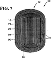
内部シール18は、概ね、上流端部28と下流端部30との間においてフィルタジャケット12の内部に配設される。好ましい実施の形態では、内部シール18は、周方向であり、上流端部28に最も接近して配設される(図2)。内部シール18の付近におけるフィルタジャケット12の断面図を例示する図7において示したように、内部シールは、フィルタジャケットの内側表面22とフィルタ媒体の外側表面72との間に介装され、好ましくは、それらの各々と封止的に係合する。内部シール18を形成する一つの有利な様式は、溝付きフィルタ媒体16が第二のスリーブ96の中に装着して配置された後(しかし、第一のスリーブは取り付けずに)、広がったレセプタクル部分104の中に封止接着剤のビードを連続的に供給することである。
The
溝付きフィルタ媒体16および第二のスリーブ96の組合せは、封止接着剤(硬化していない状態では幾分か粘着性の流体である)のビードを受容するためのレセプタクルを提供する連続的な環状溝を提供する。この接着剤のビードは、ジャケット12の内壁(より詳細には、第二のスリーブ96の広がったレセプタクル部分)、および溝付きフィルタ媒体パック16の外側表面の両者の全周および周辺に係合して完全に封止するに足るほど十分に厚い。結果として、接着剤は、一旦乾燥して硬化すると、内部シール18を形成し、濾過されてない流体がフィルタエレメントを通じて上流端部から下流端部まで短絡することを防止する。
The combination of
ジャケット12の二つのスリーブ94、96は、摩擦嵌合または他の適当なカップリングによって共に保持されることも可能であるが、好ましくは、二つのスリーブ94、96は、内部シール18によって一体的に接着され、共にジャケット12を形成する。封止接着剤の連続的なビードが溝(第二のスリーブ96と溝付きフィルタ媒体16との間に形成される)の中に供給された直後に、第一のスリーブ94は、第二のスリーブ96の中に入れ子式に(telescopically)挿入され、溝付きフィルタ媒体16を覆うので、それは接着剤に係合してスリーブコンポーネントを共に接着させる。空隙領域の中に接着剤を押し込んで押圧することによって、この構造は、さらに、ジャケットの内壁との間における完全な周方向接触をより有効に保証し、内部シール18をより確実に提供する。内部シール18は、好ましくは、ウレタンまたは糊等の接着剤から形成されるが、他の適当な封止接着剤材料から構成されてもよく、封止特性と接着特性の両方を提供する。開示したこの実施の形態の構造を使用すれば、接着剤の単一のビードが、このように、流体の短絡を防止するだけでなく、コンポーネントを共に接着するという二つの独立した機能を提供する。
The two
しかし、接着剤のビードは、あまり厚く塗布されるものではなく、湿気放出開口14の妨害にはならない。図4では強調されている湿気放出開口14は、流体(たとえば水)がフィルタエレメント10内部から排出されることを許容するよう構成される。図4および図5において集合的に例示されているように、湿気放出開口14は、好ましくは、オフセットしたフード50によってカバーされおよび/または覆われる。フード50は、ジャケット12の中において、好ましくは第一のスリーブ94の中において、構造体として一体的にモールド成形されてもよい。オフセットしたフード50は、概ね、一対のフランジ52によってジャケット12の外側周囲表面24から外側方向に離間され、カバー54は湿気放出開口14の上方で位置決めされる。それ故、湿気放出開口14は、通過する流体の流れを制限することなく、保護的にカバーされる。湿気放出開口14がこのような様式で保護されるので、フィルタエレメント10(図1)内の溝付きフィルタ媒体16は、開放された流路をなお残しつつ、穿刺、不正開封および他の損傷から安全である。
However, the adhesive bead is not very thickly applied and does not interfere with the
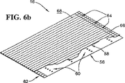
ジャケット12の中に装着されるフィルタ媒体16の形式は、さまざまな形態を採ってもよく、好ましくは、軸方向流形式のものである(深度媒体、溝付き媒体は、しばしば軸方向であり、襞付き媒体も軸方向流用として配置することができる)。高いフィルタリング能力を提供するという見地からの好ましい形態のうちの一つは、例示したような溝付きフィルタ媒体16である。前述の特許は、溝付きフィルタ媒体の方法および構造が周知であることを示している。したがって、本明細書における詳細は、追加の引例に関してはこれらの先行技術の特許文献が参照され得るので、比較的限定的である。好ましくはフィルタジャケット12の内部に配設される溝付きフィルタ媒体16は、図6Bでは巻回されていない状態で示されている。図示のように、溝付きフィルタ媒体16は、断続的に共に接着されその後に巻き上げられるフィルタ材料から構成される平面シート56および溝付きシート58を備える。好ましい一つの実施の形態では、平面シート56および溝付きシート58の一方または両方は、同じ材料で形成されるものであり、天然材料(たとえば、セルロース濾紙)および/または合成材料もよい。溝付きシート58は、波形成形することによって、すなわちシート濾紙において接近した折り目を形成することによって形成され得るものであり、交互の山と谷を形成する。
The format of the
溝付きフィルタ媒体16は、さまざまな異なった様式(たとえば巻回ボードの有無など)によって構成することができる。一つの具体例では、図6A−図6Cにおいて集合的かつ順番に例示されているように、ステッチ接着剤60が、平面シート56と溝付きシート58の間において断続的に中央に配置され、その一方で、別の接着剤62(たとえばウレタン)が、好ましくは平面シートおよび溝付きシートの縁部に近接して連続的に配置されて、「A」シール62を形成する。これらの接着剤は、二枚のシートが共に接合される前に、溝付きシート58および/または平面シート56の何れかの上においてビードとして塗布することができる。その後、平面シート56および溝付きシート58は、集合的に共に接合され、二枚のシートの間に接着剤材料を挟んで、二枚のシートを共に接着させる。
The
平面シート56および溝付きシート58が共に接着された後、好ましくは接着した平面シート56および溝付きシート58の縁部から幾分か離して、更なる接着剤66が溝付きシート58の頂部表面68上に配置される。一旦これが行われたならば、溝付きフィルタ媒体は、巻回されて巻き上げられ得ることになり、二枚のシート56、58の露出表面を互いに接触させる。この接着剤66は、平面シート56および溝付きシート58が併せて巻き上げられるとき、「B」シール64を形成する。必要に応じて、接着剤66に加えて、更なるステッチ接着剤(図示せず)が、平面シート56および/または溝付きシート58の何れかまたは両方の露出表面上に配置されてもよく、溝付きフィルタ媒体16の巻回したパックの構造の完全性を提供し、空気流および圧力に曝されるときの溝付きフィルタ媒体の伸縮(telescoping)または他の破損を防止する。
After the
接合した平面シート56および溝付きシート58が併せて巻回されおよび/または共に巻き付けられるので、複数の溝70(図1)を有する溝付きフィルタ媒体16が形成される。複数の溝70の中における溝の一つのグループは、上流端部28に近接して閉鎖され、その一方で、複数の溝の中における溝の別のグループは、下流端部30に近接して閉鎖される。上述の通り、好ましくは、それらの溝は、溝を閉じて封止することによって閉鎖されるが、それらの溝は、押し潰すかまたは他のそのような閉鎖手段によって閉鎖されてもよい。それに加えて、閉鎖および封止の場所は、フィルタ媒体16の端部に正確に配置されるかまたはそこから幾分か離間されてもよい(典型的には、図6A−図6Cで示すように、一方のシールビードは端部表面に配され、他方のものは幾分か凹部に配される)。近接とは、本明細書では、溝付きフィルタ媒体のすべてのさまざまな潜在的配置および構造を包含するように使用されている。
Because the joined
溝付きフィルタ媒体16が空気流に曝されるとき、空気は、入口表面において開口する溝70のグループの中に流れ込む。これらの溝70は、出口表面に近接して閉鎖されているので、空気は、濾紙を通じて、出口表面において開口した(入口表面に近接して閉鎖した)溝70の中に押し込まれ、フィルタ媒体パックから排出される。それ故、上流端部28から下流端部30まで溝付きフィルタ媒体16を通じて流れる汚染された空気は、溝付きフィルタ媒体を通じて押し込まれ、そのため、粒子状物質および汚染物質が開放入口溝の壁に沿って捕捉されて浄化される。
When the
内部シール18は、概ね、上流端部28と下流端部30との間においてフィルタジャケット12の内部に配設される。好ましい実施の形態では、内部シール18は、周形状であり、上流端部28に最も接近して配設される(図1)。内部シール18の付近におけるフィルタジャケット12の断面図を例示している図7において示したように、内部シールは、フィルタジャケットの内側表面22とフィルタ媒体の外側表面72との間に介装され、それらの各々と封止的に係合する。
The
図1において示したように、外部シール20は、略楕円形で好ましくは圧縮可能なシール材料であり、下流端部30に近接してフィルタジャケット12に固定される。外部シール20および内部シール18は、互いに離間した関係にあり、溝付きフィルタ媒体16は、フィルタジャケット12の内部に配設され、フィルタジャケット12によって取り囲まれる。
As shown in FIG. 1, the
シールは、予め形成したガスケットまたは他のそのようなフォームインプレイス・シール材料であってもよいが、開示した実施の形態は、モールド成形されて直接にフィルタジャケット12に取り付けられる、より詳細には環状のシールサポート部材74を介して第二のスリーブ96に取り付けられる、発泡ウレタンシールを利用する。図8における例示では、外部シール20が取り外されて、フィルタジャケット12上に一体的に形成される環状のシールサポート部材74を露出させている。環状のシールサポート部材74は、軸に対して傾斜し、異なって傾斜したセクションを含むことにより、径方向外向きに傾斜した部分76と径方向内向きに傾斜した部分78とを含んでいる。例示したように、径方向内向きに傾斜した部分78は、リブネットワーク42に近接して配設される。
The seal may be a preformed gasket or other such foam-in-place seal material, but the disclosed embodiment is molded and attached directly to the
径方向に傾斜した部分76は、その中に形成される複数の貫通孔80すなわち開口を含む。貫通孔80は、外部シール20を形成する自由隆起シール形成材料(たとえば発泡ウレタン等)を受容する。貫通孔80を貫通して突出するシール材料の各部分は、外部シール20を環状のシールサポート部材74に対してロックする。シール材料は、概ね、環状のシールサポート部材74の回りを流れるだけでなく、貫通孔80の中に流入しかつそれを通じて流れることをも許容される。その材料が硬化しあるいは凝固すると、貫通孔80の内部における固化しあるいは硬化した材料は、新しく形成された外部シール20をシールサポート部材74に対してロックしおよび/または固定する。
The radially inclined
図8および図9の両者を参照すると、第二のスリーブ96、したがってジャケット12もまた、不連続なフランジ82を含む。不連続なフランジ82は、下流端部30に近接したフィルタジャケット12の外側環状壁21から径方向外向きに延在する。不連続なフランジ82は、概ねフィルタジャケット12の回りに延在するが、封止用の当該フランジ内の断続的なギャップ84によって別個のセクションに分割される。封止用のフランジ82は、製造の間に利用されて、モールド成形の間に膨張して自由に隆起する性質がある発泡ウレタン材料のための上限すなわち境界を提供する。断続的なギャップ84は、自由隆起シール材料が当該ギャップを通じて、そして好ましくは封止用のフランジを越えて、上向きに膨張することを許容する。自由隆起シール形成材料が少なくとも部分的にギャップ84を通じて隆起するように許容することによって、外部シール20の適当であるかまたは好ましい構造が、視覚的検査によって確認され得ることになる。たとえば、さまざまなギャップ84を人が検査できることになり、シール材料は、ギャップの中にまで少なくとも部分的に突出していることが確認される。材料がそれらのギャップの中に到達するまで発泡しないならば、そのような徴候は、シールモールド成形プロセスに付随する潜在的な問題を表示し得ることになる。ギャップ84の別個の利点は、シール材料がギャップの中に達するまで突出し、それによってシールサポート部材74とは異なった場所および平面において外部シール20をフィルタジャケット12に対してロックすることである。さらに、それらのギャップのさらに別の潜在的な利点は、発泡タイプウレタンのモールド成形プロセスの間に形成されるガスの通気を可能にすることである。
With reference to both FIGS. 8 and 9, the
続いて、図10および図11を参照すると、フィルタジャケット12は、さらに、下流端部30に近接したバッフル90を含み、バッフル90はまた所望のシール形成の制御を支援する。バッフル90は、溝付きフィルタ媒体16の出口表面に被せて配設され、バッフル表面92はフィルタ媒体16から軸方向に離間する。図示の通り、バッフル90は、フィルタジャケットの内側表面22の近接個所から下流端部30に向かって径方向内向きに突出する。バッフル90は、外部シール20がモールド成形プロセスの間に形成されるとき、自由隆起シール材料の流れを案内するよう構成されて配置されるバッフル表面92を含む。詳細には、バッフル表面92は、シール形成材料の自由隆起表面に面して、膨張の間、材料をガイドする。
With continued reference to FIGS. 10 and 11, the
図示した実施の形態では、バッフル90は、フィルタジャケットの内側表面22に近接し、かつフィルタジャケットの内側表面22から径方向に離間していて、環状の自由隆起膨張領域および環状ガス通気孔110をそれらの間に形成する。図10および図11の両方において示すように、バッフル90は、リブネットワーク86のリブを径方向に延在させることによって、離間されて一体的に支持される。バッフル90とフィルタジャケットの内側表面22との間の環状膨張領域内では、シール材料は、(図11Aにおける方向矢印によって規定したように)発泡して、不規則な自由隆起表面112を形成することを許容される。これに対して、外部シールの残りの表面は、規則的であり、モールド成形された、従って形状を制御された表面114を形成する。このモールド成形表面114は、不連続なフランジ82において始まり、シールサポート部材74の回りに巻回される。モールド成形表面114の内側径方向表面は、公差が厳しいものでもあり、下流のダクトまたはハウジングの適当な封止表面に対するシールを形成するよう構成される径方向封止表面を提供するように形成される。
In the illustrated embodiment, the
この実施の形態では、バッフル90は、自由隆起表面が溝付きフィルタ媒体16の出口表面に向かって延在するとき、自由隆起表面112を径方向外向きに案内するように配置される。外部シール20のシール材料は、バッフル90に接触するかまたはそこから離間されてもよい。外部シール20のシール材料がシールモールド成形プロセスの間に隆起するとき、シール材料がバッフル表面92に係合した場合、シール材料は、環状通気孔110に向かって径方向外向きに押し出される。したがって、バッフル90は、シール材料を溝付きフィルタの端部表面から離すように案内し(かつ、自由隆起表面があまりに高く張り出した場合、フィルタ媒体の端部表面との接触を最小化し)、さらには、モールド成形表面114の内側径方向周面に沿って設けられる封止表面の完全性をも維持する。
In this embodiment, the
図9においても示したように、フィルタジャケット12は、溝付きフィルタ媒体16の端部表面の回りに延在してフィルタ媒体を(たとえば、濾過の間に発生する空気圧に対抗して)支持する下流端部30に近接したウェブネットワーク86を含む。ウェブネットワーク86は、流体が通ることをなお許容しつつ、溝付きフィルタ媒体16をフィルタジャケット12の内部に支持するよう構成される。ウェブネットワーク86は、概ね、一つ以上の個別のリブ88を含む。
As also shown in FIG. 9, the
車両内のインラインダクトの中に装着されるとき、突起38は、ダクト上のクランプと位置合わせされ、ボス34、36は、車両上のハウジングの嵌合部分と位置合わせされる。これは、湿気放出開口14が配置されるフィルタエレメント10の重力底部26が、重力の方向または引っ張りに対して適切に位置決めされることを保証する。その後、突起38の各々は、好ましくは、ダクトに対してクランプ留めされ、ボス34、36の各々は、車両のハウジングに対して固定され、フィルタエレメント10の位置を固定する。
When mounted in an in-line duct in the vehicle, the
運転に際して、フィルタエレメント10は、上流端部28に近接して、汚染された空気および/または汚れた空気の流れを受け入れる。汚れた空気は、上流端部28に近接して溝の中に入り、溝付きフィルタ媒体16を通り抜け、汚染物質は汚れた空気から取り除かれ、浄化されあるいは濾過された空気は、溝のうちの他のものによって下流端部30において排出される。何らかの湿気または水分が内部シール18の上流においてフィルタエレメント10の中に入ったとしても、その水分は、湿気放出開口14を通じて排水することができる。湿気放出開口14が、好ましくは、フィルタエレメント10の重力底部にあるいはその付近に位置決めされるので、重力は、その流体を自然に引っ張り、あるいは引き出すように利用される。それ故、内部シール18の上流においてフィルタジャケット12の内部に見出される何らかの水分は、排水され、あるいは浸出されることが許容される。
In operation, the
所定量の時間(すなわちフィルタ寿命)の後、フィルタエレメントを通り抜ける空気から取り除かれた汚染物質は、フィルタエレメントを消耗させ、フィルタエレメントの効率を低下させ、フィルタエレメントを目詰まりさせるようなことになる。これが生じると、フィルタエレメント10は、インラインダクトから取り外され、新しいフィルタエレメントと交換される。都合のよいことに、湿気放出開口14は、このように、フィルタエレメントが交換されるたびに、フィルタエレメントと共に交換される。したがって、湿気放出開口14は、フィルタエレメントの定期的な交換の故に、目詰まりしたり妨害を受けたりすることにはならないのである。
After a predetermined amount of time (ie, filter life), contaminants removed from the air passing through the filter element will wear the filter element, reduce the efficiency of the filter element, and clog the filter element. . When this occurs, the
本明細書に引用された、出版物、特許出願および特許を含む全ての参考文献は、その各々が引用により組み込まれるよう個別且つ具体的に示され、また、その全体が本明細書中に述べられたかのように引用により組み込まれる。 All references cited herein, including publications, patent applications and patents, are individually and specifically indicated to be incorporated by reference, and are set forth herein in their entirety. It is incorporated by reference as if it were.
本発明の説明の文脈で(特に特許請求の範囲の文脈で)用いられる名詞及び同様な指示語の使用は、本明細書中で特に指摘したり、明らかに文脈と矛盾したりしない限り、単数および複数の両方に及ぶものと解釈される。語句「備える」、「有する」、「含む」および「包含する」は、特に断りのない限り、オープンエンドターム(すなわち「〜を含むが限定しない」という意味)として解釈される。本明細書中の数値範囲の具陳は、本明細書中で特に指摘しない限り、単にその範囲内に該当する各値を個々に言及するための略記法としての役割を果たすことだけを意図しており、各値は、本明細書中で個々に列挙されるかのように、明細書に組み込まれる。本明細書中で説明されるすべての方法は、本明細書中で特に指摘したり、明らかに文脈と矛盾したりしない限り、あらゆる適切な順番で行うことができる。本明細書中で使用するあらゆる例または例示的な言い回し(例えば「など」)は、特に主張しない限り、単に本発明をよりよく説明することだけを意図し、本発明の範囲に対する制限を設けるものではない。明細書中の如何なる言い回しも、本発明の実施に不可欠である、特許請求の範囲に記載されていない要素を示すものとは解釈されないものとする。 The use of nouns and similar directives used in the context of the description of the present invention (especially in the context of the claims) is intended to be singular unless specifically indicated herein or otherwise contradicted by context. And to be interpreted as extending to both. The phrases “comprising”, “having”, “including” and “including” are to be interpreted as open-ended terms (ie, including but not limited to) unless otherwise specified. The use of numerical ranges in this specification is intended only to serve as a shorthand for referring individually to each value falling within that range, unless otherwise indicated herein. Each value is incorporated into the specification as if it were individually listed herein. All methods described herein can be performed in any suitable order unless otherwise indicated herein or otherwise clearly contradicted by context. Any examples or exemplary phrases used herein (eg, “etc.”) are intended only to better describe the invention, unless otherwise stated, and to limit the scope of the invention. is not. No language in the specification should be construed as indicating any non-claimed element as essential to the practice of the invention.
本明細書中では、発明を実施するため本発明者が知っている最良の形態を含め、本発明の好ましい実施の形態について説明している。当業者にとっては、上記説明を読んだ上で、これらの好ましい実施の形態の変形が明らかとなろう。本発明者は、熟練者がこのような変形を適宜用いるであろうことを予期し、本発明が本明細書中で具体的に説明される以外の方法で実施されることを意図している。従って本発明は、準拠法で許されているように、本明細書に添付された請求項に記載の主題の修正および均等物をすべて含む。さらに、本明細書中で特に指摘したり、明らかに文脈と矛盾したりしない限り、すべての考えられる変形における上記要素のいずれの組合せも本発明に包含される。 In the present specification, preferred embodiments of the present invention are described, including the best mode known to the inventors for carrying out the invention. Variations of these preferred embodiments will become apparent to those skilled in the art after reading the above description. The inventor anticipates that the skilled person will use such variations as appropriate, and that the present invention is intended to be practiced otherwise than as specifically described herein. . Accordingly, this invention includes all modifications and equivalents of the subject matter recited in the claims appended hereto as permitted by applicable law. Moreover, any combination of the above-described elements in all possible variations thereof is encompassed by the invention unless otherwise indicated herein or otherwise clearly contradicted by context.
本明細書の中に組み込まれ、かつその一部を形成する添付図面は、本発明の幾つかの態様を例示するものであり、さらには、その記述と共に、本発明の原理を説明するように供されるものでもある。 The accompanying drawings, which are incorporated in and form a part of this specification, illustrate several aspects of the present invention and, together with the description, explain the principles of the invention. It is also provided.
Claims (11)
前記外側壁部が前記フィルタジャケットの内側表面を画成し;
さらに、前記フィルタジャケットの内部に存在してフィルタ媒体外側表面を画成する、溝付きのフィルタ媒体であって、複数の溝を有し、前記複数の溝のうちの第一の選択がされたものは前記上流端部に近接して閉鎖され、前記複数の溝のうちの第二の選択がされたものは前記下流端部に近接して閉鎖される、溝付きのフィルタ媒体と;
前記フィルタジャケットの内側表面と前記フィルタ媒体外側表面との間に形成される内部シールであって、前記上流端部と前記下流端部との間に配設される内部シールと;
前記フィルタジャケットの前記外側壁部を貫通して形成され、前記内部シールの上流に配置される、重力により前記フィルタジャケット内の水分を排水する排水開口とを備え;
前記フィルタジャケットは、前記排水開口と位置合わせされるフードをさらに備え;
前記フードは、前記排水開口を保護的にカバーし;
前記フードは、フランジおよびカバーを有し;
前記フランジは、前記フィルタジャケットから径方向外向きに突出し;
前記カバーは、前記フィルタジャケットから径方向外向きに離間し、かつ前記フランジに結合する;
フィルタエレメント。A filter jacket having an outer wall extending between an upstream end and a downstream end;
The outer wall defines an inner surface of the filter jacket;
A grooved filter medium that is present within the filter jacket and defines an outer surface of the filter medium, the grooved filter medium having a plurality of grooves, the first of the plurality of grooves being selected. A grooved filter medium, wherein one is closed proximate to the upstream end and a second selected one of the plurality of grooves is closed proximate to the downstream end;
An internal seal formed between the inner surface of the filter jacket and the outer surface of the filter medium, the internal seal disposed between the upstream end and the downstream end;
Wherein said filter jacket through the outer wall portion is formed, is located upstream of the internal seal, Bei example a drainage opening for draining water in the filter jacket by gravity;
The filter jacket further comprises a hood aligned with the drain opening;
The hood protectively covers said drain openings;
The hood has a flange and a cover;
The flange projects radially outward from the filter jacket;
The cover is spaced radially outward from the filter jacket and is coupled to the flange;
Filter element.
前記第一のスリーブおよび前記第二のスリーブは、共に結合されて前記ジャケットを形成し;
前記内部シールの材料は、前記第一および第二のスリーブの間における境界に位置して前記第一および第二のスリーブを共に接着し;
前記第一のスリーブおよび前記第二のスリーブは、前記第一のスリーブおよび前記第二のスリーブのそれぞれ、または逆のそれぞれにおける位置合わせノッチおよび位置合わせリブにより、角度的に位置合わせされる;
請求項1に記載のフィルタエレメント。The filter jacket further comprises a first sleeve and a second sleeve;
The first sleeve and the second sleeve are joined together to form the jacket;
The material of the inner seal is located at a boundary between the first and second sleeves to bond the first and second sleeves together;
The first sleeve and the second sleeve are angularly aligned by alignment notches and alignment ribs in each of the first sleeve and the second sleeve, or vice versa;
The filter element according to claim 1.
請求項2に記載のフィルタエレメント。The alignment rib projects only partially into the alignment notch leaving an open gap forming the drainage opening;
The filter element according to claim 2 .
前記第一のスリーブおよび前記第二のスリーブは、共に結合されて前記ジャケットを形成し;
前記内部シールの材料は、前記第一および第二のスリーブの間における境界に位置して前記第一および第二のスリーブを共に接着し;
前記第一のスリーブは、入口端部に近接して配設され、前記第二のスリーブは、出口端部に近接して配設され、前記排水開口は、前記第一のスリーブにおいて形成される;
請求項1乃至請求項3のいずれか1項に記載のフィルタエレメント。The filter jacket further comprises a first sleeve and a second sleeve;
The first sleeve and the second sleeve are joined together to form the jacket;
The material of the inner seal is located at a boundary between the first and second sleeves to bond the first and second sleeves together;
The first sleeve is disposed proximate to the inlet end, the second sleeve is disposed proximate to the outlet end, and the drainage opening is formed in the first sleeve. ;
The filter element according to any one of claims 1 to 3 .
請求項1乃至請求項4のいずれか1項に記載のフィルタエレメント。The filter jacket is fluid permeable through the drain opening upstream of the inner seal and fluid impermeable downstream of the inner seal;
The filter element according to any one of claims 1 to 4 .
請求項1乃至請求項5のいずれか1項に記載のフィルタエレメント。The filter element further comprises an external seal attached to the filter jacket proximate to the downstream end;
The filter element according to any one of claims 1 to 5 .
前記貫通孔は、前記外部シールを形成するために用いられるシール形成材料を受容して固定するよう構成された;
請求項6に記載のフィルタエレメント。An annular seal support member includes a plurality of circumferentially spaced through holes extending from the filter jacket proximate to the downstream end;
The through hole is configured to receive and secure a seal-forming material used to form the outer seal;
The filter element according to claim 6 .
前記挿入端部は、前記外向きに広がったレセプタクル部分の中に入れ子式に受容される;
請求項1乃至請求項7のいずれか1項に記載のフィルタエレメント。The filter jacket is formed from a first sleeve having an insertion end and a second sleeve having an outwardly extending receptacle portion;
The insertion end is telescopically received in the outwardly extending receptacle portion;
The filter element according to any one of claims 1 to 7 .
請求項1乃至請求項8のいずれか1項に記載のフィルタエレメント。The filter jacket is formed of plastic and defines means for gravity positioning the drainage opening proximate to the gravity bottom of the inner surface of the filter jacket;
The filter element according to any one of claims 1 to 8 .
封止用の前記フランジは、一つ以上の断続的なギャップを画成し、外側シールが、前記封止用のフランジに係合し、前記一つ以上の断続的なギャップを通じて少なくとも部分的に突出する;
請求項1乃至請求項9のいずれか1項に記載のフィルタエレメント。The filter jacket includes an annular wall extending in the axial direction and a discontinuous flange extending outwardly from the annular wall adjacent to the downstream end;
The sealing flange defines one or more intermittent gaps, and an outer seal engages the sealing flange and is at least partially through the one or more intermittent gaps. Protrude;
The filter element according to any one of claims 1 to 9 .
前記バッフルは、前記下流端部に向かって前記フィルタジャケットの内側表面の近接個所から径方向内向きに突出し、前記バッフルは、シール形成材料の自由隆起表面に面して、前記シール形成材料の前記自由隆起表面の流れを案内するよう配置されたバッフル表面を有する;
請求項1乃至請求項10のいずれか1項に記載のフィルタエレメント。The filter jacket includes a baffle proximate to the downstream end;
The baffle projects radially inward from a proximal location on the inner surface of the filter jacket toward the downstream end, the baffle facing a free raised surface of the seal forming material, and the baffle of the seal forming material Having a baffle surface arranged to guide the flow of the free raised surface;
The filter element according to any one of claims 1 to 10 .
Applications Claiming Priority (3)
| Application Number | Priority Date | Filing Date | Title |
|---|---|---|---|
| US11/357,788 | 2006-02-17 | ||
| US11/357,788 US7753982B2 (en) | 2006-02-17 | 2006-02-17 | Filter with drained jacket, seal indicator/lock means, and seal baffle |
| PCT/US2007/003865 WO2007097954A2 (en) | 2006-02-17 | 2007-02-12 | Filter with drained jacket, seal indicator/lock means, and seal baffle |
Publications (2)
| Publication Number | Publication Date |
|---|---|
| JP2009526648A JP2009526648A (en) | 2009-07-23 |
| JP4956557B2 true JP4956557B2 (en) | 2012-06-20 |
Family
ID=38426753
Family Applications (1)
| Application Number | Title | Priority Date | Filing Date |
|---|---|---|---|
| JP2008555317A Active JP4956557B2 (en) | 2006-02-17 | 2007-02-12 | Filter with drainage jacket, seal indicator / locking means, and seal baffle |
Country Status (7)
| Country | Link |
|---|---|
| US (1) | US7753982B2 (en) |
| EP (1) | EP1996309B1 (en) |
| JP (1) | JP4956557B2 (en) |
| AU (1) | AU2007217983B2 (en) |
| BR (1) | BRPI0707760A8 (en) |
| CA (1) | CA2641786C (en) |
| WO (1) | WO2007097954A2 (en) |
Cited By (2)
| Publication number | Priority date | Publication date | Assignee | Title |
|---|---|---|---|---|
| US10359011B2 (en) | 2013-05-22 | 2019-07-23 | Donaldson Company, Inc. | Vertical air intake system; air cleaner; and filter element |
| US11185809B2 (en) | 2007-11-15 | 2021-11-30 | Donaldson Company, Inc. | Air filter arrangements; assemblies; and, methods |
Families Citing this family (64)
| Publication number | Priority date | Publication date | Assignee | Title |
|---|---|---|---|---|
| EP0904143B1 (en) * | 1996-04-26 | 2003-06-18 | Donaldson Company, Inc. | Fluted filter media |
| KR20050098922A (en) | 2003-02-11 | 2005-10-12 | 도널드선 컴파니 인코포레이티드 | Air cleaner arrangements; serviceable filter elements;and,method |
| US8226786B2 (en) | 2003-03-18 | 2012-07-24 | Donaldson Company, Inc. | Process and materials for coiling z-filter media, and/or closing flutes of filter media; and, products |
| CN101816872B (en) | 2004-03-24 | 2013-12-11 | 唐纳森公司 | Filter elements, air cleaner, assembly, and methods |
| US7993434B2 (en) * | 2004-04-06 | 2011-08-09 | Oscar Moreno A | Disposable air filter assembly |
| GB0409548D0 (en) * | 2004-04-29 | 2004-06-02 | King S College London | Robotic hand |
| AU2005240577B2 (en) | 2004-04-30 | 2010-11-04 | Donaldson Company, Inc. | Filter arrangements; housings; assemblies; and, methods |
| US7905936B2 (en) | 2004-04-30 | 2011-03-15 | Donaldson Company, Inc. | Filter arrangements; housing; assemblies; and, methods |
| EP1781397B1 (en) | 2004-06-18 | 2013-06-12 | Donaldson Company, Inc. | Air cleaner arrangements and methods |
| ATE457810T1 (en) | 2004-07-20 | 2010-03-15 | Donaldson Co Inc | Z-FILTER MEDIA PACKING ASSEMBLY, FILTER CARTRIDGE, AIR PURIFICATION DEVICE ASSEMBLY AND METHOD |
| US20110197556A1 (en) | 2004-11-02 | 2011-08-18 | Baldwin Filters, Inc. | Filter element |
| US7931725B2 (en) | 2004-11-02 | 2011-04-26 | Baldwin Filters, Inc. | Fluted filter apparatus |
| US7318851B2 (en) | 2004-11-02 | 2008-01-15 | Baldwin Filters, Inc. | Filter element |
| US7909954B2 (en) * | 2004-11-03 | 2011-03-22 | Baldwin Filters, Inc. | Method and apparatus for winding a filter media pack |
| US7569090B2 (en) | 2004-11-12 | 2009-08-04 | Donaldson Company, Inc. | Method of forming filter arrangements; and, apparatus |
| DE102004059279B4 (en) * | 2004-12-09 | 2018-05-03 | Mann + Hummel Gmbh | air filter |
| RU2008117336A (en) | 2005-10-11 | 2009-11-20 | Дональдсон Компани, Инк. (Us) | AIR FILTER CARTRIDGE AND AIR CLEANER |
| DE102006001126A1 (en) | 2006-01-09 | 2007-07-12 | Kettenbach Gmbh & Co. Kg | Dental impression compounds, hardened products prepared therefrom and use of surfactants for the production of dental impression compounds |
| US7736410B2 (en) | 2006-01-20 | 2010-06-15 | Donaldson Company, Inc. | Air cleaner configured for receipt of various sized filter cartridges; components thereof; and, methods |
| US7753982B2 (en) | 2006-02-17 | 2010-07-13 | Baldwin Filters, Inc. | Filter with drained jacket, seal indicator/lock means, and seal baffle |
| JP4661677B2 (en) * | 2006-04-25 | 2011-03-30 | トヨタ紡織株式会社 | Air filter and manufacturing method thereof |
| JP2009541643A (en) | 2006-06-22 | 2009-11-26 | ドナルドソン カンパニー,インコーポレイティド | AIR CLEANER COMPOSITION, ITS COMPONENT, AND ITS MANUFACTURING METHOD |
| US7713321B2 (en) | 2006-06-22 | 2010-05-11 | Donaldson Company, Inc. | Air cleaner arrangements; components thereof; and, methods |
| US9757676B2 (en) | 2006-12-06 | 2017-09-12 | Baldwin Filters, Inc. | Method and apparatus for winding a filter element |
| US10040020B2 (en) * | 2006-12-06 | 2018-08-07 | Baldwin Filters, Inc. | Fluid filter apparatus having filter media wound about a winding frame |
| US8460420B2 (en) * | 2007-09-07 | 2013-06-11 | Parker-Hannifin Corporation | Filter element |
| US8728193B2 (en) * | 2007-09-07 | 2014-05-20 | Donaldson Company, Inc. | Air filter assembly; components thereof and methods |
| US9545593B2 (en) | 2007-11-01 | 2017-01-17 | Baldwin Filters, Inc. | Winding core pressure relief for fluted filter |
| US7959703B2 (en) | 2008-06-30 | 2011-06-14 | Baldwin Filters, Inc. | Fluted filter with integrated frame |
| US8048187B2 (en) | 2008-06-30 | 2011-11-01 | Baldwin Filters, Inc. | Filter frame attachment and fluted filter having same |
| CN104524873B (en) * | 2008-07-22 | 2017-07-21 | 唐纳森公司 | Air cleaner assembly and its part |
| WO2010099317A2 (en) | 2009-02-27 | 2010-09-02 | Donaldson Company, Inc. | Filter cartridge; components thereof; and methods |
| US8506668B2 (en) | 2009-03-30 | 2013-08-13 | Baldwin Filters, Inc. | Fluted filter with axial seal |
| US8287614B2 (en) * | 2009-08-10 | 2012-10-16 | Mann+Hummel Gmbh | Supplemental filter media support insert for an air cleaner |
| US9174160B2 (en) * | 2009-08-19 | 2015-11-03 | Baldwin Filters, Inc. | Collapsible core, filter, and method |
| EP2547419A4 (en) | 2010-03-17 | 2013-08-28 | Baldwin Filters Inc | Fluid filter |
| WO2011115979A2 (en) | 2010-03-17 | 2011-09-22 | Baldwin Filters, Inc. | Fluid filter |
| WO2012037433A1 (en) | 2010-09-16 | 2012-03-22 | Cummins Filtration Ip Inc. | Filter element with features to improve pre-cleaning performance, sealing, and structural support |
| US8562722B2 (en) | 2010-12-22 | 2013-10-22 | Cooper Technologies Company | Structural reinforcements for filter assemblies |
| CA2987984C (en) | 2010-12-22 | 2019-12-31 | Cooper Technologies Company | Pre-filtration and maintenance sensing for explosion-proof enclosures |
| KR20140030131A (en) * | 2011-01-11 | 2014-03-11 | 만 운트 훔멜 게엠베하 | Air cleaner assembly and filter element providing improved dynamic wall stiffness |
| US8721986B2 (en) * | 2011-09-09 | 2014-05-13 | Mann+Hummel Gmbh | Freshening clip cabin air cleaner |
| US9970394B2 (en) | 2012-07-25 | 2018-05-15 | Baldwin Filters, Inc. | Filter housing, fluted filter and safety filter |
| EP2885063A4 (en) | 2012-08-20 | 2016-03-09 | Ecolab Usa Inc | Mercury sorbents |
| DE102013019327B4 (en) * | 2013-11-20 | 2023-06-01 | Mann+Hummel Gmbh | Filter element with filter bellows and use of the filter element |
| EP3204140A4 (en) * | 2014-10-10 | 2018-09-05 | Baldwin Filters, Inc. | Filter media and filter element with adhesive reinforcing |
| USD786935S1 (en) * | 2015-11-20 | 2017-05-16 | Baldwin Filters, Inc. | Filter element |
| WO2017087325A1 (en) * | 2015-11-20 | 2017-05-26 | Baldwin Filters, Inc. | Adhesive flute support while winding fluted pack |
| USD798907S1 (en) * | 2015-11-20 | 2017-10-03 | Baldwin Filters, Inc. | Filter element |
| US10682597B2 (en) | 2016-04-14 | 2020-06-16 | Baldwin Filters, Inc. | Filter system |
| EP3311902B1 (en) * | 2016-10-24 | 2020-06-24 | Donaldson Company, Inc. | Air filter element and method for producing same |
| US11235275B2 (en) * | 2017-03-16 | 2022-02-01 | Cummins Filtration Ip, Inc. | Filtration sealing system |
| USD852345S1 (en) * | 2017-04-07 | 2019-06-25 | Champion Laboratories, Inc. | Filter |
| MX2020001477A (en) | 2017-08-09 | 2020-03-20 | Donaldson Co Inc | Filter cartridges; air cleaner assemblies; housings; features; components; and, methods. |
| USD885546S1 (en) * | 2017-08-09 | 2020-05-26 | Donaldson Company, Inc. | Filter cartridge |
| USD885545S1 (en) * | 2017-08-09 | 2020-05-26 | Donaldson Company, Inc. | Filter cartridge |
| WO2019113152A1 (en) | 2017-12-08 | 2019-06-13 | Cummins Filtration Ip, Inc. | Oval seal with stabilization contour |
| CN111757776B (en) | 2018-01-12 | 2022-01-25 | 康明斯滤清系统知识产权公司 | Air filter easy to maintain |
| US10918978B2 (en) | 2018-05-08 | 2021-02-16 | Cummins Filtration Ip, Inc. | Oval filter with exterior elliptical radial seal and internal support structure |
| USD884866S1 (en) | 2018-05-08 | 2020-05-19 | Cummins Filtration Ip, Inc. | Filter element |
| USD1002792S1 (en) | 2019-02-05 | 2023-10-24 | Donaldson Company, Inc. | Filter cartridge |
| CN113727771B (en) * | 2019-02-08 | 2023-09-26 | 唐纳森公司 | Filter element, air cleaner assembly and method |
| USD969289S1 (en) | 2020-03-05 | 2022-11-08 | Cummins Filtration Inc. | Filter element |
| US20240042361A1 (en) * | 2022-08-06 | 2024-02-08 | Baldwin Filters, Inc. | Embedding variable slit width embossed filter media packs |
Family Cites Families (141)
| Publication number | Priority date | Publication date | Assignee | Title |
|---|---|---|---|---|
| US1947066A (en) | 1932-12-14 | 1934-02-13 | Samuel M Langston Co | Corrugator |
| US1954881A (en) | 1933-03-23 | 1934-04-17 | Samuel M Langston Co | Corrugator |
| US1943080A (en) | 1933-04-21 | 1934-01-09 | Samuel M Langston | Corrugator |
| US3025963A (en) * | 1958-03-13 | 1962-03-20 | Russell H Curtis | Products useful as filtering devices and methods of making them |
| US3255889A (en) | 1961-04-10 | 1966-06-14 | American Mach & Foundry | Wound filter |
| SE302235B (en) | 1966-02-08 | 1968-07-08 | Svenska Flaektfabriken Ab | |
| GB1121896A (en) | 1966-07-21 | 1968-07-31 | Gen Motors Ltd | Air filters |
| US3676247A (en) | 1969-02-03 | 1972-07-11 | Australian Paper Manufacturers | Corrugating paperboard |
| US3679057A (en) | 1970-09-11 | 1972-07-25 | Damasco Rodolfo Adelto Perez | Screen filter pack and method for making same |
| US4253228A (en) | 1978-09-14 | 1981-03-03 | Filterspun, Inc. | Apparatus and system for forming wound filters |
| US4252591A (en) | 1979-05-02 | 1981-02-24 | Pall Corporation | Corrugating apparatus and process |
| US4257790A (en) | 1979-10-10 | 1981-03-24 | Henningsen Foods, Inc. | Quick change filter bag arrangement |
| EP0152513B1 (en) * | 1981-02-23 | 1991-01-09 | Nippondenso Co., Ltd. | Filter element for fluid cleaner systems |
| US4410427A (en) * | 1981-11-02 | 1983-10-18 | Donaldson Company, Inc. | Fluid filtering device |
| US4579698A (en) | 1982-05-28 | 1986-04-01 | Amf, Inc. | Process for producing a microporous polymeric filter membrane with adjacent non-porous edge layers and a pleated filter element formed from the membrane |
| SE452598B (en) | 1985-06-20 | 1987-12-07 | Flodins Filter Ab | PROCEDURE AND DEVICE FOR FILTER MANUFACTURING |
| US4747944A (en) * | 1986-04-29 | 1988-05-31 | Midwest Conservation Specialties, Inc. | Recirculating filter system |
| US4720292B1 (en) * | 1986-07-14 | 1991-09-10 | Cylindrical air filter with lightweight housing and radially directed seal | |
| GB8621660D0 (en) * | 1986-09-09 | 1986-10-15 | Domnick Hunter Filters Ltd | Filter element |
| SE455378B (en) | 1986-11-17 | 1988-07-11 | Flodins Filter Ab | PROCEDURE FOR MANUFACTURING FILTERS |
| DE8810295U1 (en) * | 1988-08-13 | 1988-10-13 | Stanelle, Karl-Heinz, 7129 Gueglingen, De | |
| US5346675A (en) | 1988-12-16 | 1994-09-13 | Usui Kokusai Sangyo Kabushiki Kaisha | Exhaust gas cleaning apparatus |
| US4976857A (en) | 1989-05-03 | 1990-12-11 | Newport Filters, Inc. | Filter element and fabrication methodology |
| JPH038568U (en) * | 1989-06-14 | 1991-01-28 | ||
| US5238474A (en) * | 1990-10-19 | 1993-08-24 | Donaldson Company, Inc. | Filtration arrangement |
| US5213275A (en) | 1991-07-17 | 1993-05-25 | General Dynamics Corporation, Space Systems Division | Reeding edge for securing in place fiber band during filament winding operation |
| US5245897A (en) | 1991-11-25 | 1993-09-21 | E. I. Du Pont De Nemours And Company | System and method for advancing the leading edge of a corrugated web |
| DE59207005D1 (en) | 1992-03-04 | 1996-10-02 | Ciba Geigy Ag | Method and device for winding windable substrates |
| JP3239517B2 (en) | 1992-06-17 | 2001-12-17 | 株式会社デンソー | Manufacturing method of filtration element |
| DE4223723C2 (en) | 1992-07-18 | 1996-08-29 | Mann & Hummel Filter | Method and device for producing a zigzag folded filter |
| US5484466A (en) * | 1994-02-14 | 1996-01-16 | Baldwin Filters, Inc. | Air filter element with radial seal sealing gasket |
| JPH07236803A (en) * | 1994-02-28 | 1995-09-12 | Tsuchiya Mfg Co Ltd | Disposable oil filter for internal combustion engine |
| SE506017C2 (en) | 1994-05-10 | 1997-11-03 | Volvo Ab | Air Filter |
| WO1995035202A1 (en) | 1994-06-21 | 1995-12-28 | Miller Ray R | Method of bonding laminates and resulting laminates |
| US5938804A (en) * | 1994-11-23 | 1999-08-17 | Donaldson Company, Inc. | Reverse flow air filter arrangement and method |
| US5588945A (en) | 1995-02-21 | 1996-12-31 | Corrugated Gear & Services, Inc. | Method and device for spacing a corrugating finger relative to a corrugating roll |
| US5685985A (en) | 1995-12-20 | 1997-11-11 | Baldwin Filters, Inc. | Environmentally friendly filter cartridge |
| DE19654188C5 (en) | 1995-12-26 | 2010-09-23 | Toyoda Boshoku Corp., Kariya-shi | Filter element and method for its production |
| EP0904143B1 (en) | 1996-04-26 | 2003-06-18 | Donaldson Company, Inc. | Fluted filter media |
| US5792247A (en) | 1996-04-26 | 1998-08-11 | Donaldson Company, Inc. | Integrated resonator and filter apparatus |
| US5772883A (en) | 1996-04-26 | 1998-06-30 | Donaldson Company, Inc. | Slanted inline filter |
| US5895574A (en) * | 1996-04-26 | 1999-04-20 | Donaldson Company, Inc. | Rolled liquid filter using fluted media |
| US5820646A (en) * | 1996-04-26 | 1998-10-13 | Donaldson Company, Inc. | Inline filter apparatus |
| US5902364A (en) * | 1996-04-26 | 1999-05-11 | Donaldson Company, Inc. | Conical filter |
| US6022305A (en) | 1998-03-11 | 2000-02-08 | Aaf International | Pleating apparatus |
| ES2179599T3 (en) * | 1998-11-04 | 2003-01-16 | Rohm & Haas | PROCEDURE FOR PRODUCTION WITH HIGH PERFORMANCE OF METHYL METHYLRATE OR METACRYLIC ACID. |
| US6210469B1 (en) | 1999-02-26 | 2001-04-03 | Donaldson Company, Inc. | Air filter arrangement having first and second filter media dividing a housing and methods |
| US6179890B1 (en) * | 1999-02-26 | 2001-01-30 | Donaldson Company, Inc. | Air cleaner having sealing arrangement between media arrangement and housing |
| US6221122B1 (en) * | 1999-02-26 | 2001-04-24 | Donaldson Company, Inc. | Filter element and methods |
| US6235195B1 (en) * | 1999-02-26 | 2001-05-22 | Donaldson Company, Inc. | Filter element incorporating a handle member |
| BR0008458B1 (en) * | 1999-02-26 | 2010-11-30 | filter sealing system. | |
| US6190432B1 (en) | 1999-02-26 | 2001-02-20 | Donaldson Company, Inc. | Filter arrangement; sealing system; and methods |
| USD450827S1 (en) | 1999-02-26 | 2001-11-20 | Donaldson Company, Inc. | Filter element having sealing system |
| USD461003S1 (en) | 1999-02-26 | 2002-07-30 | Donaldson Company, Inc. | Filter element having sealing system |
| DE19935297A1 (en) | 1999-07-27 | 2001-02-01 | Mahle Filtersysteme Gmbh | Filter body of a fluid filter, especially an air filter |
| USD437402S1 (en) | 1999-11-05 | 2001-02-06 | Donaldson Company, Inc. | Filter element with centerpiece |
| US6348084B1 (en) | 1999-11-05 | 2002-02-19 | Donaldson Company, Inc. | Filter element, air cleaner, and methods |
| US6348085B1 (en) | 1999-11-10 | 2002-02-19 | Donaldson Company, Inc. | Filter arrangement and methods |
| US6416605B1 (en) | 1999-11-24 | 2002-07-09 | Donaldson Company, Inc. | Method for manufacturing fluted media |
| US6290739B1 (en) * | 1999-12-29 | 2001-09-18 | Donaldson Company, Inc. | Aerosol separator; and method |
| US6436162B1 (en) | 2000-03-22 | 2002-08-20 | Nelson Industries, Inc. | Twist and lock filter housing with anti-rotation stop |
| DE10023427A1 (en) | 2000-05-12 | 2001-11-15 | Mann & Hummel Filter | Liquid filter comprises housing which holds filter cartridge, lid, and inlet and outlet |
| US6946012B1 (en) | 2000-05-18 | 2005-09-20 | Fleetguard, Inc. | Filter and forming system |
| USD450828S1 (en) | 2000-06-13 | 2001-11-20 | Donaldson Company, Inc. | Fluted filter element having a handle |
| US6368374B1 (en) | 2000-06-13 | 2002-04-09 | Donaldson Company, Inc. | Filter arrangement and methods |
| US6673136B2 (en) * | 2000-09-05 | 2004-01-06 | Donaldson Company, Inc. | Air filtration arrangements having fluted media constructions and methods |
| US6743273B2 (en) | 2000-09-05 | 2004-06-01 | Donaldson Company, Inc. | Polymer, polymer microfiber, polymer nanofiber and applications including filter structures |
| US6800117B2 (en) * | 2000-09-05 | 2004-10-05 | Donaldson Company, Inc. | Filtration arrangement utilizing pleated construction and method |
| US6402798B1 (en) | 2000-09-19 | 2002-06-11 | Nelson Industries, Inc. | Twist and lock filter housing with nontorsional anti-rotation stop |
| US6511599B2 (en) | 2000-12-18 | 2003-01-28 | Nelson Industries, Inc. | Multi-element cylindrical filter with equalized flow |
| US6743317B2 (en) * | 2000-12-19 | 2004-06-01 | Robert M. Wydeven | Method of sealing, housing and constructing honeycomb filters |
| US6797027B2 (en) * | 2001-04-11 | 2004-09-28 | Donaldson Company, Inc. | Filter assemblies and systems for intake air for fuel cells |
| US6447567B1 (en) * | 2001-05-14 | 2002-09-10 | Baldwin Filters, Inc. | Air filter element with integral radial seal gasket |
| RU2300543C2 (en) | 2001-05-31 | 2007-06-10 | Дональдсон Компани, Инк. | Fine fiber compositions, methods for preparation thereof, and a method of manufacturing fine-fiber material |
| USD460169S1 (en) | 2001-06-06 | 2002-07-09 | Donaldson Company Inc. | Filter element having an inlet grid |
| US6517598B2 (en) * | 2001-06-06 | 2003-02-11 | Donaldson Company, Inc. | Filter element having flange and methods |
| US6610126B2 (en) | 2001-06-06 | 2003-08-26 | Donaldson Company, Inc. | Filter element having sealing members and methods |
| US6852141B2 (en) | 2001-06-06 | 2005-02-08 | Donaldson Company, Inc. | Filter element having center piece and methods |
| DE10152552A1 (en) * | 2001-10-24 | 2003-05-08 | Mann & Hummel Filter | Filter element, in particular for the filtration of liquids |
| JP3946027B2 (en) * | 2001-10-29 | 2007-07-18 | 和興フィルタテクノロジー株式会社 | air cleaner |
| USD473637S1 (en) | 2001-12-03 | 2003-04-22 | Donaldson Company, Inc. | Fluted filter element |
| DE60236887D1 (en) | 2001-12-03 | 2010-08-12 | Donaldson Co Inc | FILTER ELEMENTS WITH FOLDED FILTER MEDIA |
| USD483459S1 (en) | 2002-01-23 | 2003-12-09 | Donaldson Company, Inc. | Air filter element for engine |
| US6966940B2 (en) * | 2002-04-04 | 2005-11-22 | Donaldson Company, Inc. | Air filter cartridge |
| US6851569B2 (en) | 2002-04-22 | 2005-02-08 | Plastican, Inc. | Reusable lid and container |
| ATE541632T1 (en) | 2002-05-09 | 2012-02-15 | Donaldson Co Inc | SIDE ACCESS AIR CLEANER HOUSING |
| US7168573B2 (en) | 2002-06-07 | 2007-01-30 | Baldwin Filters, Inc. | Environmentally friendly filter cartridge |
| DE10227050B3 (en) | 2002-06-17 | 2004-01-29 | Albert Frey Verpackungsentwicklungen Und Vertriebs-Gmbh | Corrugated cardboard with tear line |
| EP1521627B1 (en) | 2002-07-10 | 2011-02-16 | Donaldson Company, Inc. | Fluted filter medium and process for its manufacture |
| US6703675B1 (en) * | 2002-08-20 | 2004-03-09 | Memx, Inc. | Particle filter for partially enclosed microelectromechanical systems |
| US6959819B2 (en) | 2002-10-08 | 2005-11-01 | Pti Technologies, Inc. | Fatigue rated glass filled plastic filter assembly incorporating a coreless plastic filter element with integral seal |
| US7537631B2 (en) * | 2002-10-28 | 2009-05-26 | Donaldson Company, Inc. | Filter cartridges; air cleaners; and methods |
| USD497202S1 (en) * | 2002-11-22 | 2004-10-12 | Donaldson Company, Inc. | Filter for engine |
| US7282075B2 (en) | 2002-12-11 | 2007-10-16 | Donaldson Company, Inc. | Z-filter media with reverse-flow cleaning systems and methods |
| US6887343B2 (en) | 2002-12-20 | 2005-05-03 | Fleetguard, Inc. | Filter coating, winding, finishing and manufacturing system |
| USD484584S1 (en) | 2003-01-22 | 2003-12-30 | Donaldson Company, Inc. | Filter element for engine |
| KR20050098922A (en) | 2003-02-11 | 2005-10-12 | 도널드선 컴파니 인코포레이티드 | Air cleaner arrangements; serviceable filter elements;and,method |
| US8226786B2 (en) | 2003-03-18 | 2012-07-24 | Donaldson Company, Inc. | Process and materials for coiling z-filter media, and/or closing flutes of filter media; and, products |
| US7008465B2 (en) | 2003-06-19 | 2006-03-07 | Donaldson Company, Inc. | Cleanable high efficiency filter media structure and applications for use |
| US7458468B2 (en) | 2003-08-05 | 2008-12-02 | Purolator Filters Na Llc | Fuel filter diverter |
| US20070137152A1 (en) | 2003-10-17 | 2007-06-21 | Jian Xu | Precleaner arrangement for use in air filtration, method of operation of precleaner and air cleaner comprising the precleaner arrangement |
| EP2316557B1 (en) | 2003-11-12 | 2017-04-26 | Donaldson Company, Inc. | Air filter with slide mount for filtering element |
| WO2005058461A1 (en) | 2003-12-16 | 2005-06-30 | Donaldson Company, Inc. | Air cleaner arrangement and methods |
| CA2550734C (en) | 2003-12-22 | 2015-06-30 | Donaldson Company, Inc. | Filter element comprising a seal arrangement and method for making the same |
| WO2005082484A1 (en) | 2004-02-09 | 2005-09-09 | Donaldson Company, Inc. | Pleated corrugated filter media |
| WO2005077487A1 (en) | 2004-02-10 | 2005-08-25 | Donaldson Company, Inc. | Media arrangement; filter constructions; and, methods |
| ATE477041T1 (en) | 2004-02-17 | 2010-08-15 | Donaldson Co Inc | AIR PURIFIER ASSEMBLY, SERVICEABLE FILTER ELEMENTS AND METHODS |
| US7311748B2 (en) * | 2004-03-02 | 2007-12-25 | Parker-Hannifin Corporation | Air filter assembly system and method |
| CN101816872B (en) * | 2004-03-24 | 2013-12-11 | 唐纳森公司 | Filter elements, air cleaner, assembly, and methods |
| USD506539S1 (en) | 2004-03-24 | 2005-06-21 | Donaldson Company, Inc. | Filter cartridge |
| US7905936B2 (en) | 2004-04-30 | 2011-03-15 | Donaldson Company, Inc. | Filter arrangements; housing; assemblies; and, methods |
| CN100484601C (en) | 2004-06-08 | 2009-05-06 | 唐纳森公司 | Z-filter media pack arrangements and methods |
| WO2005123222A1 (en) | 2004-06-14 | 2005-12-29 | Donaldson Company, Inc. | Air filter arrangement; assembly; and, methods |
| EP1781397B1 (en) | 2004-06-18 | 2013-06-12 | Donaldson Company, Inc. | Air cleaner arrangements and methods |
| ATE457810T1 (en) * | 2004-07-20 | 2010-03-15 | Donaldson Co Inc | Z-FILTER MEDIA PACKING ASSEMBLY, FILTER CARTRIDGE, AIR PURIFICATION DEVICE ASSEMBLY AND METHOD |
| WO2006014941A2 (en) | 2004-07-26 | 2006-02-09 | Donaldson Company, Inc. | Z-filter media pack arrangement; and, methods |
| GB0417458D0 (en) * | 2004-08-05 | 2004-09-08 | Domnick Hunter Ltd | Filter assembly |
| MX2007001427A (en) | 2004-08-06 | 2007-04-02 | Donaldson Co Inc | Air filter arrangement; assembly; and, methods. |
| US20060091064A1 (en) | 2004-11-02 | 2006-05-04 | Baldwin Filters, Inc. | Filter apparatus with separable seal support frame |
| US20060091061A1 (en) | 2004-11-02 | 2006-05-04 | Baldwin Filters, Inc. | Filter assembly with sealing system |
| US8042694B2 (en) | 2004-11-02 | 2011-10-25 | Baldwin Filters, Inc. | Gathered filter media for an air filter and method of making same |
| US7318851B2 (en) * | 2004-11-02 | 2008-01-15 | Baldwin Filters, Inc. | Filter element |
| US20060091084A1 (en) | 2004-11-02 | 2006-05-04 | Baldwin Filters, Inc. | Fluted filter media with intermediate flow restriction and method of making same |
| US20070186528A1 (en) * | 2006-02-15 | 2007-08-16 | Baldwin Filters, Inc. | Fluted filter apparatus |
| US7255300B2 (en) | 2004-11-03 | 2007-08-14 | Baldwin Filters, Inc. | Method and apparatus for winding a filter media pack |
| EP1838414B1 (en) | 2005-01-13 | 2012-03-07 | Donaldson Company, Inc. | Air filter arrangement |
| CN102512889B (en) | 2005-01-13 | 2015-11-25 | 唐纳森公司 | Air filter cartridge and air cleaner assembly |
| US8083825B2 (en) | 2005-02-28 | 2011-12-27 | Donaldson Company, Inc. | Filter arrangement and method |
| WO2007009039A1 (en) | 2005-07-13 | 2007-01-18 | Donaldson Company, Inc. | Air filter cartridge and air filter |
| RU2008117336A (en) | 2005-10-11 | 2009-11-20 | Дональдсон Компани, Инк. (Us) | AIR FILTER CARTRIDGE AND AIR CLEANER |
| CN102302880A (en) | 2005-11-09 | 2012-01-04 | 唐纳森公司 | Seal arrangement for filter element |
| US7736410B2 (en) | 2006-01-20 | 2010-06-15 | Donaldson Company, Inc. | Air cleaner configured for receipt of various sized filter cartridges; components thereof; and, methods |
| US7753982B2 (en) | 2006-02-17 | 2010-07-13 | Baldwin Filters, Inc. | Filter with drained jacket, seal indicator/lock means, and seal baffle |
| US7625419B2 (en) | 2006-05-10 | 2009-12-01 | Donaldson Company, Inc. | Air filter arrangement; assembly; and, methods |
| WO2007145939A2 (en) | 2006-06-12 | 2007-12-21 | Donaldson Company, Inc. | Rolled axial flow filter and methods |
| US7713321B2 (en) | 2006-06-22 | 2010-05-11 | Donaldson Company, Inc. | Air cleaner arrangements; components thereof; and, methods |
| JP2009541643A (en) | 2006-06-22 | 2009-11-26 | ドナルドソン カンパニー,インコーポレイティド | AIR CLEANER COMPOSITION, ITS COMPONENT, AND ITS MANUFACTURING METHOD |
| WO2008045325A2 (en) | 2006-10-06 | 2008-04-17 | Donaldson Company, Inc. | Air cleaner assembly, air cleaner filter cartridge, and method of servicing an air cleaner assembly |
| EP2514506B1 (en) | 2007-02-02 | 2019-08-14 | Donaldson Company, Inc. | Air filtration media pack and methods |
| US20100233048A1 (en) | 2007-02-09 | 2010-09-16 | Donaldson Company, Inc | Combination filter element |
| JP5385792B2 (en) | 2007-02-26 | 2014-01-08 | ドナルドソン カンパニー,インコーポレイティド | Filter composition, air cleaner assembly and method |
-
2006
- 2006-02-17 US US11/357,788 patent/US7753982B2/en active Active
-
2007
- 2007-02-12 WO PCT/US2007/003865 patent/WO2007097954A2/en active Application Filing
- 2007-02-12 AU AU2007217983A patent/AU2007217983B2/en active Active
- 2007-02-12 JP JP2008555317A patent/JP4956557B2/en active Active
- 2007-02-12 EP EP07750687.1A patent/EP1996309B1/en active Active
- 2007-02-12 CA CA 2641786 patent/CA2641786C/en active Active
- 2007-02-12 BR BRPI0707760A patent/BRPI0707760A8/en not_active Application Discontinuation
Cited By (2)
| Publication number | Priority date | Publication date | Assignee | Title |
|---|---|---|---|---|
| US11185809B2 (en) | 2007-11-15 | 2021-11-30 | Donaldson Company, Inc. | Air filter arrangements; assemblies; and, methods |
| US10359011B2 (en) | 2013-05-22 | 2019-07-23 | Donaldson Company, Inc. | Vertical air intake system; air cleaner; and filter element |
Also Published As
| Publication number | Publication date |
|---|---|
| JP2009526648A (en) | 2009-07-23 |
| US7753982B2 (en) | 2010-07-13 |
| BRPI0707760A2 (en) | 2011-05-10 |
| EP1996309A4 (en) | 2014-11-05 |
| AU2007217983A1 (en) | 2007-08-30 |
| EP1996309B1 (en) | 2019-05-01 |
| BRPI0707760A8 (en) | 2018-04-24 |
| US20070193236A1 (en) | 2007-08-23 |
| WO2007097954A3 (en) | 2008-01-17 |
| AU2007217983B2 (en) | 2011-02-03 |
| WO2007097954A2 (en) | 2007-08-30 |
| CA2641786C (en) | 2013-11-26 |
| EP1996309A2 (en) | 2008-12-03 |
| CA2641786A1 (en) | 2007-08-30 |
Similar Documents
| Publication | Publication Date | Title |
|---|---|---|
| JP4956557B2 (en) | Filter with drainage jacket, seal indicator / locking means, and seal baffle | |
| CA2642345C (en) | Fluted filter apparatus | |
| CN113153587B (en) | Filter element, air cleaner assembly, and methods of use and assembly | |
| US7318851B2 (en) | Filter element | |
| US7708796B2 (en) | Axial flow filter element | |
| EP1203609B1 (en) | Open flow filter with safety element | |
| US8048187B2 (en) | Filter frame attachment and fluted filter having same | |
| JP5133420B2 (en) | Filter element and filter system | |
| US7931725B2 (en) | Fluted filter apparatus | |
| CA2670487C (en) | Fluted filter with integrated frame | |
| US8673043B2 (en) | Fluid filter | |
| BR112018012466B1 (en) | FILTER CARTRIDGES AND AIR PURIFIER ASSEMBLIES | |
| MX2008010551A (en) | Fluted filter apparatus |
Legal Events
| Date | Code | Title | Description |
|---|---|---|---|
| A621 | Written request for application examination |
Free format text: JAPANESE INTERMEDIATE CODE: A621 Effective date: 20091124 |
|
| A977 | Report on retrieval |
Free format text: JAPANESE INTERMEDIATE CODE: A971007 Effective date: 20110722 |
|
| A131 | Notification of reasons for refusal |
Free format text: JAPANESE INTERMEDIATE CODE: A131 Effective date: 20110802 |
|
| A521 | Request for written amendment filed |
Free format text: JAPANESE INTERMEDIATE CODE: A523 Effective date: 20111024 |
|
| TRDD | Decision of grant or rejection written | ||
| A01 | Written decision to grant a patent or to grant a registration (utility model) |
Free format text: JAPANESE INTERMEDIATE CODE: A01 Effective date: 20120228 |
|
| A01 | Written decision to grant a patent or to grant a registration (utility model) |
Free format text: JAPANESE INTERMEDIATE CODE: A01 |
|
| A61 | First payment of annual fees (during grant procedure) |
Free format text: JAPANESE INTERMEDIATE CODE: A61 Effective date: 20120316 |
|
| R150 | Certificate of patent or registration of utility model |
Free format text: JAPANESE INTERMEDIATE CODE: R150 Ref document number: 4956557 Country of ref document: JP Free format text: JAPANESE INTERMEDIATE CODE: R150 |
|
| FPAY | Renewal fee payment (event date is renewal date of database) |
Free format text: PAYMENT UNTIL: 20150323 Year of fee payment: 3 |
|
| R250 | Receipt of annual fees |
Free format text: JAPANESE INTERMEDIATE CODE: R250 |
|
| R250 | Receipt of annual fees |
Free format text: JAPANESE INTERMEDIATE CODE: R250 |
|
| R250 | Receipt of annual fees |
Free format text: JAPANESE INTERMEDIATE CODE: R250 |
|
| R250 | Receipt of annual fees |
Free format text: JAPANESE INTERMEDIATE CODE: R250 |
|
| R250 | Receipt of annual fees |
Free format text: JAPANESE INTERMEDIATE CODE: R250 |
|
| R250 | Receipt of annual fees |
Free format text: JAPANESE INTERMEDIATE CODE: R250 |
|
| R250 | Receipt of annual fees |
Free format text: JAPANESE INTERMEDIATE CODE: R250 |
|
| R250 | Receipt of annual fees |
Free format text: JAPANESE INTERMEDIATE CODE: R250 |
|
| R250 | Receipt of annual fees |
Free format text: JAPANESE INTERMEDIATE CODE: R250 |
|
| R250 | Receipt of annual fees |
Free format text: JAPANESE INTERMEDIATE CODE: R250 |