BR122018000115B1 - Process for the production of paper rolls, and industrial installation for the production of paper rolls - Google Patents
Process for the production of paper rolls, and industrial installation for the production of paper rolls Download PDFInfo
- Publication number
- BR122018000115B1 BR122018000115B1 BR122018000115-1A BR122018000115A BR122018000115B1 BR 122018000115 B1 BR122018000115 B1 BR 122018000115B1 BR 122018000115 A BR122018000115 A BR 122018000115A BR 122018000115 B1 BR122018000115 B1 BR 122018000115B1
- Authority
- BR
- Brazil
- Prior art keywords
- coils
- rewinder
- transport unit
- cores
- accumulator
- Prior art date
Links
Images


Classifications
-
- B—PERFORMING OPERATIONS; TRANSPORTING
- B65—CONVEYING; PACKING; STORING; HANDLING THIN OR FILAMENTARY MATERIAL
- B65H—HANDLING THIN OR FILAMENTARY MATERIAL, e.g. SHEETS, WEBS, CABLES
- B65H19/00—Changing the web roll
- B65H19/22—Changing the web roll in winding mechanisms or in connection with winding operations
- B65H19/2238—The web roll being driven by a winding mechanism of the nip or tangential drive type
- B65H19/2269—Cradle
-
- B—PERFORMING OPERATIONS; TRANSPORTING
- B65—CONVEYING; PACKING; STORING; HANDLING THIN OR FILAMENTARY MATERIAL
- B65H—HANDLING THIN OR FILAMENTARY MATERIAL, e.g. SHEETS, WEBS, CABLES
- B65H18/00—Winding webs
-
- B—PERFORMING OPERATIONS; TRANSPORTING
- B65—CONVEYING; PACKING; STORING; HANDLING THIN OR FILAMENTARY MATERIAL
- B65H—HANDLING THIN OR FILAMENTARY MATERIAL, e.g. SHEETS, WEBS, CABLES
- B65H19/00—Changing the web roll
-
- B—PERFORMING OPERATIONS; TRANSPORTING
- B65—CONVEYING; PACKING; STORING; HANDLING THIN OR FILAMENTARY MATERIAL
- B65H—HANDLING THIN OR FILAMENTARY MATERIAL, e.g. SHEETS, WEBS, CABLES
- B65H2301/00—Handling processes for sheets or webs
- B65H2301/40—Type of handling process
- B65H2301/41—Winding, unwinding
- B65H2301/417—Handling or changing web rolls
- B65H2301/41704—Handling or changing web rolls involving layout of production or storage facility
Abstract
PROCESSO PARA A PRODUÇÃO DE ROLOS DE PAPEL, E INSTALAÇÃO INDUSTRIAL PARA A PRODUÇÃO DE ROLOS DE PAPEL Processo para a produção de rolos de papel, compreendendo uma etapa de produção de bobinas (L) de trama de papel mediante enrolamento de uma predeterminada quantidade de trama de papel (W) sobre um núcleo tubular (C) orientado transversalmente em relação a uma direção (PP) da entrada da trama de papel (W) numa rebobinadeira (R) em que o referido enrolamento é executado, e uma etapa de corte transversal das bobinas (L) para obter rolos (R) de comprimento predeterminado. Os núcleos (C) são produzidos por uma máquina de formação de tubos (T) cuja posição é interceptada pela direção (PP) do papel (W) que adentra na rebobinadeira (R).PROCESS FOR THE PRODUCTION OF PAPER ROLLS, AND INDUSTRIAL INSTALLATION FOR THE PRODUCTION OF PAPER ROLLS Process for the production of paper rolls, comprising a step of producing reels (L) of paper weft by winding a predetermined amount of weft of paper (W) on a tubular core (C) oriented transversely with respect to a direction (PP) of the entry of the paper web (W) in a rewinder (R) in which said winding is carried out, and a step of transverse cutting from the spools (L) to obtain rolls (R) of predetermined length. The cores (C) are produced by a tube forming machine (T) whose position is intercepted by the direction (PP) of the paper (W) that enters the rewinder (R).
Description
[0001] A presente invenção está relacionada a uma instalação industrial e a um processo para a produção de rolos de papel.[0001] The present invention is related to an industrial installation and a process for the production of paper rolls.
[0002] É sabido que a produção de bobinas de papel envolve a alimentação de uma trama de papel contínuo ao longo de um percurso predefinido. Num ponto predeterminado do referido percurso, um corte transversal descontínuo é feito no papel de modo a subdividi-lo em porções ou folhas possuindo cada uma um comprimento predeterminado.[0002] It is known that the production of paper reels involves feeding a web of continuous paper along a predefined path. At a predetermined point on said path, a discontinuous cross-section is made in the paper so as to subdivide it into portions or sheets each having a predetermined length.
[0003] Esta técnica conhecida envolve o uso de elementos tubulares constituídos de papelão, usualmente referidos como núcleos, sobre cuja superfície é distribuída uma quantidade predeterminada de cola para permitir a colagem da primeira folha da bobina a ser formada.[0003] This known technique involves the use of tubular elements made of cardboard, usually referred to as cores, on whose surface a predetermined amount of glue is distributed to allow the gluing of the first sheet of the coil to be formed.
[0004] Esta técnica também proporciona a utilização de rolos bobinadores, posicionados e atuantes numa estação de formação de bobinas, os quais induzem a rotação do núcleo sobre o qual a trama de papel é enrolada. A formação de uma bobina é completada depois que uma quantidade predeterminada de papel é enrolada sobre o núcleo. Neste ponto, outra bobina é formada. No final do processo de formação de bobinas é necessário colar a última folha de cada bobina numa outra subjacente, a fim de evitar o desenrolamento espontâneo da trama de papel. Máquinas de corte são em seguida usadas para subdividir cada bobina em vários rolos de comprimento menor a serem embalados.[0004] This technique also provides the use of winding rolls, positioned and acting in a coil forming station, which induce the rotation of the core on which the paper web is wound. The formation of a bobbin is completed after a predetermined amount of paper is wound onto the core. At this point, another coil is formed. At the end of the reel forming process, it is necessary to glue the last sheet of each reel to an underlying one, in order to avoid spontaneous unwinding of the paper web. Slitting machines are then used to subdivide each coil into several smaller length rolls to be packaged.
[0005] De forma geral, a produção de rolos de papel de acordo com o esquema descrito acima exige que as máquinas de formação de tubos que produzem os núcleos e as máquinas de corte sejam orientadas de forma transversal relativamente ao percurso seguido pelo papel. Isso implica, no entanto, na necessidade de áreas muito grandes e, portanto, de altos investimentos, que são necessários para a aquisição das referidas áreas. Tipicamente, uma instalação industrial do tipo descrito acima, de fato ocupa uma superfície muito grande.[0005] In general, the production of paper rolls according to the scheme described above requires that the tube forming machines that produce the cores and the cutting machines are oriented transversely with respect to the path followed by the paper. This implies, however, the need for very large areas and, therefore, high investments, which are necessary for the acquisition of these areas. Typically, an industrial facility of the type described above does occupy a very large area.
[0006] O principal objetivo da presente invenção é o de propor uma instalação industrial e um processo para a produção de rolos de papel, permitindo uma redução notável do espaço necessário para a instalação das máquinas, sem comprometer a eficácia do processo ou a qualidade do produto acabado.[0006] The main objective of the present invention is to propose an industrial installation and a process for the production of paper rolls, allowing a notable reduction of the space needed for the installation of the machines, without compromising the efficiency of the process or the quality of the finished product.
[0007] Este resultado é conseguido em conformidade com o presente invento, mediante prover um sistema de uma instalação industrial e um processo com as características indicadas nas reivindicações independentes. Outras características da presente invenção são o objeto das reivindicações dependentes.[0007] This result is achieved in accordance with the present invention, by providing a system of an industrial plant and a process with the characteristics indicated in the independent claims. Other features of the present invention are the subject of the dependent claims.
[0008] Entre as principais vantagens oferecidas pela presente invenção está o fato de que, pela redução do espaço necessário para a instalação das máquinas, menos recursos econômicos são necessários, o que reflete positivamente também no custo do produto acabado. Além disso, uma vez que o ciclo de produção se altera apenas com referência a algumas fases operacionais, a instalação industrial pode ser controlada também por pessoal que normalmente opera os sistemas tradicionais. Uma vantagem adicional é o custo relativamente baixo das modificações necessárias para implementar a presente invenção no que diz respeito às instalações industriais e aos processos convencionais. Além disso, no caso de uma instalação industrial que compreende duas ou mais linhas de produção, devido à superfície menor ocupada por cada linha, as linhas podem ser dispostas próximas umas das outras e a instalação industrial ocupar uma área de menor extensão e, portanto, proporcionar a possibilidade de empregar menos operadores, em particular, um número menor de gestores de instalações industriais ou de supervisores, em comparação com uma instalação industrial convencional que tenha o mesmo número de linhas de produção.[0008] Among the main advantages offered by the present invention is the fact that, by reducing the space required for installing the machines, fewer economic resources are needed, which also reflects positively on the cost of the finished product. Furthermore, since the production cycle changes only with reference to certain operational phases, the industrial installation can also be controlled by personnel who normally operate traditional systems. An additional advantage is the relatively low cost of the modifications necessary to implement the present invention with respect to industrial facilities and conventional processes. Furthermore, in the case of an industrial installation comprising two or more production lines, due to the smaller surface occupied by each line, the lines can be arranged close to each other and the industrial installation occupies a smaller area and, therefore, provide the possibility of employing fewer operators, in particular a smaller number of industrial plant managers or supervisors, compared to a conventional industrial installation having the same number of production lines.
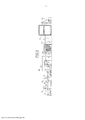
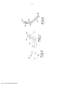
[0009] Estas e outras vantagens e características da presente invenção serão mais bem compreendidas por aquele usualmente versado na técnica, graças à descrição seguinte e aos desenhos anexos, fornecidos a título de exemplo, mas não para serem considerados no sentido limitativo, em que: A Figura 1 é uma vista esquemática de topo de uma instalação industrial de acordo com a presente invenção; A Figura 2 é uma vista esquemática lateral da instalação mostrada na Figura 1; A Figura 3 é uma vista semelhante àquela da Figura 2, mas se refere a outra modalidade da instalação industrial; A Figura 4 mostra o trajeto dos núcleos e das bobinas na área entre a rebobinadeira e a máquina de formação de tubos; A Figura 5 é um diagrama que mostra os movimentos dos núcleos na área entre a rebobinadeira e a máquina de formação de tubos; A Figura 6 mostra o percurso das bobinas e dos rolos cortados na área entre o acumulador para bobinas e a máquina de corte; As Figuras 7 a 9 representam esquematicamente uma parte da unidade de transporte de bobinas (LT); A Figura 10 é um detalhe ampliado da Figura 3.[0009] These and other advantages and features of the present invention will be better understood by one of ordinary skill in the art, thanks to the following description and the accompanying drawings, provided by way of example, but not to be considered in the limiting sense, in which: Figure 1 is a schematic top view of an industrial facility according to the present invention; Figure 2 is a schematic side view of the installation shown in Figure 1; Figure 3 is a view similar to that of Figure 2, but refers to another type of industrial installation; Figure 4 shows the path of cores and coils in the area between the rewinder and the tube forming machine; Figure 5 is a diagram showing the movements of cores in the area between the rewinder and the tube forming machine; Figure 6 shows the path of the bobbins and the cut rolls in the area between the bobbin accumulator and the cutting machine; Figures 7 to 9 schematically represent a part of the reel transport unit (LT); Figure 10 is an enlarged detail of Figure 3.
[00010] Reduzida à sua estrutura básica e com referência aos desenhos anexos, uma instalação industrial para a produção de rolos de papel (por exemplo, rolos de papel higiênico ou rolos de papel de cozinha), em conformidade com o presente invento compreende tipicamente: uma estação de desenrolamento (UP) com uma ou mais desbobinadeiras (no exemplo, as desbobinadeiras são em número de duas e estão indicadas por referências “U1” e “U2”) que suportam uma quantidade correspondente de rolos de papel (R1, R2) a partir de cada uma das quais uma camada de papel (V1, V2) desenrola; uma unidade (EG) para acoplamento das camadas de papel que chegam provenientes da estação de desenrolamento (UP), uma gravação em relevo em que as referidas camadas podem ser mutuamente gravadas e unidas por colagem para formar uma trama de papel de camada dupla (W); uma rebobinadeira (R) que num lado recebe a trama de papel (W) e no outro lado recebe os núcleos tubulares nos quais a trama de papel é enrolada de modo a formar as bobinas (L); uma máquina de formação de tubos (T), que produz os núcleos tubulares; um primeiro acumulador (CS), que recebe e acumula os núcleos produzidos pela máquina de formação de tubos (T) e alimenta a rebobinadeira (R); um segundo acumulador (LS), que recebe as bobinas produzidas pela rebobinadeira (R); uma unidade de transporte (LT), que recebe as bobinas que saem da rebobinadeira (R) e os transporta para o segundo acumulador (LS); uma máquina de corte (CM) que recebe as bobinas que chegam provenientes do segundo acumulador (LS) e as subdivide na forma de rolos de menor comprimento.[00010] Reduced to its basic structure and with reference to the accompanying drawings, an industrial plant for the production of paper rolls (e.g. toilet paper rolls or kitchen rolls) in accordance with the present invention typically comprises: an unwinding station (UP) with one or more unwinders (in the example, the unwinders are two in number and are indicated by references “U1” and “U2”) that support a corresponding number of paper rolls (R1, R2) from each of which a paper layer (V1, V2) unwinds; a unit (EG) for coupling incoming paper layers from the unwinding station (UP), an embossing in which said layers can be mutually embossed and glued together to form a double layer paper web (W ); a rewinder (R) which on one side receives the paper web (W) and on the other side receives the tubular cores on which the paper web is wound to form the bobbins (L); a tube forming machine (T), which produces the tubular cores; a first accumulator (CS), which receives and accumulates the cores produced by the tube forming machine (T) and feeds the rewinder (R); a second accumulator (LS), which receives the coils produced by the rewinder (R); a transport unit (LT), which receives the coils leaving the rewinder (R) and transports them to the second accumulator (LS); a cutting machine (CM) that receives the incoming coils from the second accumulator (LS) and subdivides them into shorter length rolls.
[00011] As desbobinadeiras (U1, U2) permitem o desenrolamento das camadas (V1, V2) a partir das bobinas (B1, B2). As referidas camadas são gravadas em relevo e coladas na estação (EG) que produz a banda (W) formada pelas camadas gravadas em relevo e coladas.[00011] The unwinders (U1, U2) allow the unwinding of the layers (V1, V2) from the coils (B1, B2). Said layers are embossed and glued at the station (EG) which produces the band (W) formed by the embossed and glued layers.
[00012] A trama alimenta a rebobinadeira (R) que proporciona o enrolamento de uma quantidade predeterminada da mesma em cada núcleo (C) que chega proveniente do primeiro acumulador (CS) e produzido pela máquina de formação de tubos (T).[00012] The weft feeds the rewinder (R) which provides the winding of a predetermined amount of it on each core (C) that arrives from the first accumulator (CS) and produced by the tube forming machine (T).
[00013] O núcleo (C) permite o enrolamento da trama (W) em torno de um eixo definido pelo eixo longitudinal do mesmo núcleo (C).[00013] The core (C) allows the winding of the weft (W) around an axis defined by the longitudinal axis of the same core (C).
[00014] As bobinas assim produzidas na rebobinadeira (R) chegam ao transportador (LT), que as transporta para o segundo acumulador (LS). Este último alimenta a máquina de corte (CM) que corta as bobinas de modo a obter rolos do comprimento desejado.[00014] The coils thus produced in the rewinder (R) arrive at the conveyor (LT), which transports them to the second accumulator (LS). The latter feeds the cutting machine (CM) which cuts the coils in order to obtain rolls of the desired length.
[00015] A máquina de formação de tubos (T) e a máquina de corte (CM) são orientadas transversalmente em relação ao percurso (PP), seguido pela trama de papel. Portanto, os núcleos produzidos pela máquina de formação de tubos (T) e que saem do último se movimentam ao longo de uma direção substancialmente perpendicular ao referido percurso (PP) e os rolos produzidos pela máquina de corte (CM) saem do último também numa direção substancialmente perpendicular ao referido percurso (PP).[00015] The tube forming machine (T) and the cutting machine (CM) are oriented transversely with respect to the path (PP), followed by the paper web. Therefore, the cores produced by the tube forming machine (T) and leaving the latter move along a direction substantially perpendicular to said path (PP) and the rolls produced by the cutting machine (CM) leave the latter also in a direction substantially perpendicular to said path (PP).
[00016] O primeiro acumulador (CS) recebe os núcleos produzidos pela máquina de formação de tubos (T) por meio de um transportador vertical (VC).[00016] The first accumulator (CS) receives the cores produced by the tube forming machine (T) through a vertical conveyor (VC).
[00017] As desbobinadeiras (U1, U2), a unidade de gravação em relevo e encolamento, a rebobinadeira, o acumulador para os núcleos, o acumulador para bobinas, a máquina de formação de tubos, os meios para transferir os núcleos das máquinas de formação de tubos para o primeiro acumulador, os meios para transferir as bobinas do segundo acumulador para a máquina de corte e a máquina de corte podem ser do tipo normalmente usado para a produção de rolos de papel.[00017] The decoilers (U1, U2), the embossing and sizing unit, the rewinder, the accumulator for cores, the accumulator for coils, the tube forming machine, the means for transferring the cores of the forming tubes for the first accumulator, the means for transferring the coils from the second accumulator to the slitting machine and slitting machine may be of the type normally used for the production of paper rolls.
[00018] As patentes europeia EP0454633 e norte-americana US6715709 divulgam rebobinadeiras; a patente internacional WO2011/089634 divulga um acumulador para núcleos tubulares de papelão; o documento internacional WO2004/01641 divulga uma máquina de formação de tubos; as patentes norte-americanas US3926299 e US3762582 revelam dispositivos para o manuseio e armazenamento de bobinas de papel.[00018] European patents EP0454633 and US US6715709 disclose rewinders; international patent WO2011/089634 discloses an accumulator for cardboard tubular cores; international document WO2004/01641 discloses a tube forming machine; US patents US3926299 and US3762582 disclose devices for handling and storing paper rolls.
[00019] De acordo com o exemplo apresentado na Figura 2, a máquina de formação de tubos (T) é colocada à jusante da máquina rebobinadeira (R) e fica posicionada sobre uma plataforma (1), sob a qual está disposta a unidade de transporte para as bobinas (LT). A máquina de corte (CM) é colocada à jusante do segundo acumulador (LS). Uma vez que a unidade de transporte (LT) impõe um desvio lateral para as bobinas enquanto elas se movimentam na direção ao segundo acumulador (LS), a máquina de corte (CM) pode ser posicionada dentro do contorno “A” da linha de produção, isto é, dentro da linha formada pelas desbobinadeiras, unidade de gravação em relevo e encolamento, rebobinadeira, primeiro acumulador e máquina de formação de tubos.[00019] According to the example presented in Figure 2, the tube forming machine (T) is placed downstream of the rewinder machine (R) and is positioned on a platform (1), under which the transport to the coils (LT). The cutting machine (CM) is placed downstream of the second accumulator (LS). Since the transport unit (LT) imposes a lateral deviation for the coils as they move towards the second accumulator (LS), the slitting machine (CM) can be positioned inside the “A” contour of the production line. , that is, within the line formed by the decoilers, embossing and sizing unit, rewinder, first accumulator and tube forming machine.
[00020] No exemplo, a unidade de transporte (LT) determina um desvio (LD) das bobinas para a esquerda, enquanto as bobinas avançam ao longo do percurso compreendido entre a rebobinadeira (R) e o segundo acumulador (LS).[00020] In the example, the transport unit (LT) determines a deviation (LD) of the coils to the left, while the coils advance along the path between the rewinder (R) and the second accumulator (LS).
[00021] Graças ao desvio lateral imposto às bobinas que se movem em direção ao segundo acumulador (LS), a máquina de corte (CM) pode ser disposta como descrito acima e isto reduz a largura total da linha de produção global em comparação com as instalações industriais tradicionais que contribuem para um avanço em linha reta das bobinas entre a rebobinadeira e o acumulador para as bobinas. Quando visto de cima, de acordo com o exemplo mostrado nos desenhos, a unidade de transporte para as bobinas (LT) é em forma-S.[00021] Thanks to the lateral deviation imposed on the coils moving towards the second accumulator (LS), the slitting machine (CM) can be arranged as described above and this reduces the overall width of the overall production line compared to the traditional industrial installations that contribute to a straight line advance of the coils between the rewinder and the accumulator for the coils. When viewed from above, according to the example shown in the drawings, the transport unit for the coils (LT) is S-shaped.
[00022] Fica entendido que, se necessário, quando visto de cima, a unidade de transporte de bobinas (LT) pode compreender uma primeira seção retilínea, uma segunda seção em forma-S, e uma terceira seção reta. De outro modo, quando vista de cima, a unidade de transporte para as bobinas (LT) pode incluir uma seção em forma-S precedida ou seguida por uma seção reta. Novamente, quando visto de cima, a unidade de transporte para as bobinas é retilínea, orientada com um ângulo predeterminado relativamente ao percurso (PP) supramencionado. Em qualquer caso, a seção de saída da unidade de transporte para as bobinas (LT) é lateralmente deslocada relativamente à linha central da rebobinadeira numa quantidade predeterminada “B”.[00022] It is understood that, if necessary, when viewed from above, the coil transport unit (LT) may comprise a first straight section, a second S-shaped section, and a third straight section. Otherwise, when viewed from above, the transport unit for the coils (LT) may include an S-shaped section preceded or followed by a straight section. Again, when viewed from above, the transport unit for the reels is rectilinear, oriented at a predetermined angle with respect to the aforementioned path (PP). In either case, the output section of the transport unit for the reels (LT) is laterally displaced with respect to the center line of the rewinder by a predetermined amount "B".
[00023] Observa-se que com os requisitos vigentes de produção, que se caracterizam pelas altas velocidades operacionais (taxa de produção de pelo menos 60 bobinas por minuto), o deslocamento lateral das bobinas (não combinado com o avanço) pode demandar uma superfície transportadora com um coeficiente de atrito extremamente alto o qual, todavia, implica em danos à superfície das bobinas.[00023] It is observed that with the current production requirements, which are characterized by high operating speeds (production rate of at least 60 coils per minute), the lateral displacement of the coils (not combined with the advance) can demand a surface conveyor with an extremely high coefficient of friction which, however, implies damage to the surface of the coils.
[00024] No passado, tal solução foi adotada, mas para taxas de produção menores (cerca de 20 bobinas por minuto). A combinação do avanço e do deslocamento lateral das bobinas implica num componente lateral de velocidade mais baixa sem impor qualquer redução das velocidades operacionais.[00024] In the past, such a solution was adopted, but for lower production rates (about 20 coils per minute). The combination of forward and lateral displacement of the coils implies a lower speed lateral component without imposing any reduction in operating speeds.
[00025] Com referência ao diagrama da Figura 1, numa instalação experimental construída pelos requerentes, a dimensão “A” era de cerca de 12,00 (doze) metros e dimensão “b” era de 2,265 metros. A instalação industrial experimental foi concebida para produzir bobinas possuindo um tamanho máximo de 2.850 milímetros.[00025] With reference to the diagram in Figure 1, in an experimental facility built by the applicants, dimension “A” was about 12.00 (twelve) meters and dimension “b” was 2.265 meters. The experimental industrial facility was designed to produce coils having a maximum size of 2,850 millimeters.
[00026] Com referência ao exemplo mostrado na Figura 3, o arranjo das máquinas (em particular, o arranjo das desbobinadeiras, unidade de gravação em relevo e encolamento, a rebobinadeira, acumuladores e máquina de corte) é o mesmo como no caso anterior, mas a máquina de formação de tubos (T) está na mesma base das demais máquinas, e a unidade de transporte (LT) tem uma seção ascendente para passar por sobre a máquina de formação de tubos (T).[00026] With reference to the example shown in Figure 3, the arrangement of the machines (in particular, the arrangement of the decoilers, embossing and gluing unit, the rewinder, accumulators and cutting machine) is the same as in the previous case, but the tube forming machine (T) is on the same base as the other machines, and the transport unit (LT) has an ascending section to go over the tube forming machine (T).
[00027] Também neste caso, a unidade de transporte (LT) obriga as bobinas a desviar lateralmente enquanto avançam no sentido ao segundo acumulador (LS).[00027] Also in this case, the transport unit (LT) forces the coils to deflect laterally as they advance towards the second accumulator (LS).
[00028] Na Figura 4 e Figura 6, onde os detalhes construtivos das máquinas individuais (em particular, os detalhes construtivos da rebobinadeira e do primeiro e segundo acumulador) não estão ilustrados, é mostrado o percurso dos núcleos (C) e as bobinas (L) na área entre a rebobinadeira (R) e a máquina de formação de tubos (T).[00028] In Figure 4 and Figure 6, where the constructive details of the individual machines (in particular, the constructive details of the rewinder and the first and second accumulator) are not illustrated, the path of the cores (C) and the coils ( L) in the area between the rewinder (R) and the tube forming machine (T).
[00029] Em particular, a Figura 4 mostra: uma primeira translação horizontal (1C) dos núcleos que saem da máquina de formação de tubos acima da unidade de transporte (LT); uma segunda translação horizontal (2C) dos núcleos (C), quando da introdução ao primeiro acumulador (CS), a segunda translação (2C) sendo ortogonal à primeira (1C); um terceiro movimento vertical ascendente (3C) de núcleos (C) num estágio anterior à saída deles a partir do primeiro acumulador (CS); um quarto movimento vertical descendente (4C) de núcleos (C) quando deixam o primeiro acumulador; uma quinta translação horizontal (5C) de núcleos (C) na direção oposta àquela do primeiro (1C); uma sexta translação horizontal (6C) de núcleos (C) quando entram na rebobinadeira (R); a unidade de transporte (LT) que determina o avanço e o simultâneo desvio lateral das bobinas (L). A Figura 5 mostra o percurso global seguido pelos núcleos (C).[00029] In particular, Figure 4 shows: a first horizontal translation (1C) of the cores leaving the tube forming machine above the transport unit (LT); a second horizontal translation (2C) of the cores (C), upon introduction to the first accumulator (CS), the second translation (2C) being orthogonal to the first (1C); a third upward vertical movement (3C) of nuclei (C) at a stage prior to their exit from the first accumulator (CS); a fourth downward vertical movement (4C) of cores (C) as they leave the first accumulator; a fifth horizontal translation (5C) of nuclei (C) in the opposite direction to that of the first (1C); a sixth horizontal translation (6C) of cores (C) as they enter the rewinder (R); the transport unit (LT) that determines the advance and the simultaneous lateral deviation of the coils (L). Figure 5 shows the global path followed by the cores (C).
[00030] A translação (1C) é determinada pela máquina de formação de tubos (T) que, durante a produção dos núcleos de (C), faz com que eles avancem; ou seja, força-os a se movimentar como mostrado na Figura 4 (seta “1C”). A translação (2C) é determinada pela seção de entrada do primeiro acumulador (CS), que é normalmente provida com uma seção de entrada que captura os núcleos provenientes da máquina de formação de tubos (T).[00030] The translation (1C) is determined by the tube forming machine (T) which, during the production of the cores of (C), makes them advance; that is, it forces them to move as shown in Figure 4 (arrow “1C”). The translation (2C) is determined by the inlet section of the first accumulator (CS), which is normally provided with an inlet section that captures the cores from the tube forming machine (T).
[00031] Dentro do primeiro acumulador (CS), os núcleos são suportados por barras moldadas que se movimentam ao longo de ma trajetória que consiste de uma sucessão de seções verticais e horizontais. A translação (3C) é a última volta dos núcleos (C) dentro do primeiro acumulador (CS).[00031] Inside the first accumulator (CS), the cores are supported by molded bars that move along a trajectory that consists of a succession of vertical and horizontal sections. The translation (3C) is the last turn of the nuclei (C) inside the first accumulator (CS).
[00032] A translação (4C) ocorre na saída dos núcleos (C) a partir do primeiro acumulador (CS) e termina com a deposição dos referidos núcleos num transportador de correia (CW) que recebe e transporta os núcleos determinando a quinta translação (5C).[00032] The translation (4C) occurs at the exit of the cores (C) from the first accumulator (CS) and ends with the deposition of said cores on a belt conveyor (CW) that receives and transports the cores determining the fifth translation ( 5C).
[00033] A sexta translação (6C) é determinada pelo fato de que o transportador (CW) é dotado, num modo já conhecido, de roletes cilíndricos inclinados (CR) que determinam o deslizamento dos núcleos (C) para a rebobinadeira: de fato os movimentos 5C e 6C são combinados mesmo se nos desenhos eles sejam representados como movimentos separados por uma questão de clareza.[00033] The sixth translation (6C) is determined by the fact that the conveyor (CW) is equipped, in a known way, with inclined cylindrical rollers (CR) that determine the sliding of the cores (C) towards the rewinder: in
[00034] Na Figura 6, onde os detalhes construtivos das máquinas individuais (em particular, os detalhes construtivos da rebobinadeira, do segundo acumulador e da máquina de corte) não estão ilustrados, é mostrado o percurso das bobinas (L) na área entre a rebobinadeira (R) e a máquina de corte (CM).[00034] In Figure 6, where the constructive details of the individual machines (in particular, the constructive details of the rewinder, the second accumulator and the cutting machine) are not illustrated, the path of the coils (L) in the area between the winder (R) and slitting machine (CM).
[00035] Em particular, a Figura 6 mostra, à jusante da unidade de transporte (LT) que, como mencionado acima, movimenta a bobina (L) ao longo de um percurso de avanço compreendendo um desvio lateral: uma primeira translação vertical ascendente (1L) de bobinas (L) quando adentrando ao segundo acumulador (LS); um segundo movimento descendente vertical (2L) de bobinas (L) num estágio antes da sua saída a partir do segundo acumulador (LS); uma terceira translação horizontal (3L) das bobinas (G), quando sai do segundo acumulador (LS); uma quarta translação horizontal (4L), ortogonal à terceira (3L), das bobinas numa etapa de avanço no sentido da lâmina da máquina de corte (CM).[00035] In particular, Figure 6 shows, downstream of the transport unit (LT) which, as mentioned above, moves the coil (L) along a forward path comprising a lateral deviation: a first upward vertical translation ( 1L) of coils (L) when entering the second accumulator (LS); a second vertical downward movement (2L) of coils (L) in a stage before their output from the second accumulator (LS); a third horizontal translation (3L) of the coils (G) when leaving the second accumulator (LS); a fourth horizontal translation (4L), orthogonal to the third (3L), of the coils in an advance step towards the cutting machine blade (CM).
[00036] Na Figura 6 os rolos produzidos pelo corte da bobina (L) por meio da máquina de corte (CM) são denotados pela referência “RO”. No interior do segundo acumulador (LS), as bobinas (L) são suportadas por barras moldadas que se movimentam ao longo da extensão de uma trajetória consistindo de uma sucessão de seções verticais e horizontais.[00036] In Figure 6 the rolls produced by cutting the coil (L) by means of the cutting machine (CM) are denoted by the reference “RO”. Inside the second accumulator (LS), the coils (L) are supported by molded bars that move along the length of a path consisting of a succession of vertical and horizontal sections.
[00037] Na sua parte terminal (parte voltada para a máquina de corte), o segundo acumulador (LS), que pode ser do tipo conhecido compreendendo uma série de barras de suporte de bobinas (PL) movimentadas por correntes, é estendido horizontalmente acima dos canais (CT) nos quais as bobinas normalmente deslizam quando ao entrar na máquina de corte.[00037] In its terminal part (part facing the cutting machine), the second accumulator (LS), which can be of the known type comprising a series of coil support bars (PL) moved by currents, is extended horizontally above of the channels (CT) in which the bobbins normally slide when entering the slitting machine.
[00038] Entre as barras de suporte de bobinas (PL) e os canais (CT) são interpostos os correspondentes assim chamados canais de pré-carga (CC) que recebem as bobinas provenientes das barras de suporte de bobinas (LS) e as descarregam por sobre os canais (CT) da máquina de corte em sincronia com os impulsores que atuam sobre as bobinas na máquina de corte de acordo com um processo já conhecido.[00038] Between the coil support bars (PL) and the channels (CT) the corresponding so-called preload channels (CC) are interposed, which receive the coils from the coil support bars (LS) and discharge them over the channels (CT) of the cutting machine in sync with the impellers that act on the coils in the cutting machine according to an already known process.
[00039] A unidade de transporte para as bobinas (LT) que fazem as bobinas a desviar lateralmente à medida que elas avançam no sentido da máquina de corte (CM) permite fazer uso de máquinas convencionais para constituir a instalação industrial e, ao mesmo tempo, permitir o posicionamento da máquina de corte (CM) e do formador de tubos (T) dentro do contorno da linha de produção disposta à montante e compreendendo a rebobinadeira (R), a unidade de gravação em relevo e encolamento (EG) e a unidade de desbobinadeira (UP).[00039] The transport unit for the coils (LT) that make the coils deflect laterally as they advance towards the cutting machine (CM) allows using conventional machines to form the industrial installation and, at the same time, , allow the positioning of the cutting machine (CM) and the tube former (T) within the contour of the production line arranged upstream and comprising the rewinder (R), the embossing and gluing unit (EG) and the uncoiler unit (UP).
[00040] A unidade de transporte para as bobinas (LT) consiste, por exemplo, de três correntes em ‘loop’ acionadas por motor constituídas por malhas (MC) mutuamente unidas por meio de articulações de bola (SM), contidas na guias (GC) possuindo a desejada orientação e equipadas, a intervalos regulares, com lâminas (PC) que em operação se destinam a ficarem em contato com a parte traseira das bobinas.[00040] The transport unit for the coils (LT) consists, for example, of three motor-driven 'loop' chains consisting of meshes (MC) mutually joined by means of ball joints (SM), contained in the guides ( GC) having the desired orientation and equipped, at regular intervals, with blades (PC) which, in operation, are intended to be in contact with the back of the coils.
[00041] Na prática, a unidade de transporte (LT) forma um desviador de fluxo para as bobinas (L), no sentido de que isso torna possível desviar o fluxo de bobinas que sai da rebobinadeira e posicionar a máquina de corte (CM) com seus canais de alimentação (CT) também numa posição defasada relativamente à rebobinadeira.[00041] In practice, the transport unit (LT) forms a flux diverter for the coils (L), in the sense that this makes it possible to divert the coil flux leaving the rewinder and position the slitting machine (CM) with its feed channels (CT) also in a position out of phase with the rewinder.
[00042] Como mostrado nos desenhos, a máquina de formação de tubos (T) está localizada dentro do contorno da linha de produção formada pelas desbobinadeiras, a unidade de gravação em relevo e encolamento e a rebobinadeira.[00042] As shown in the drawings, the tube forming machine (T) is located within the contour of the production line formed by the uncoilers, the embossing and sizing unit and the rewinder.
[00043] Em comparação com uma instalação industrial convencional, na qual a máquina de formação de tubos (T) é externa à linha de produção formada pelas desbobinadeiras, a unidade de gravação em relevo e encolamento e a rebobinadeira, há uma considerável economia de área de solo na montagem da unidade industrial de produção de bobinas. Por exemplo, para bobinas de tamanho máximo igual (comprimento de bobinas igual a 2850,00 mm) e, portanto, as mesmas máquinas usadas, num sistema tradicional a dimensão “A” anteriormente mencionado assume um valor de cerca de 20 metros. Por outro lado, tal como mencionado anteriormente, o posicionamento do tubo (T) como no diagrama da Figura 1, isto é, mediante posicionamento da máquina de formação de tubos (T) tal que ele é interceptado pela direção (PP) que representa o percurso do papel (W) proveniente das desbobinadeiras para a rebobinadeira, a dimensão “A” tem um valor de quase metade.[00043] Compared to a conventional industrial installation, in which the tube forming machine (T) is external to the production line formed by the decoilers, the embossing and gluing unit and the rewinder, there is a considerable saving in area of soil in the assembly of the industrial unit for the production of coils. For example, for reels of equal maximum size (coil length equal to 2850.00 mm) and, therefore, the same machines used, in a traditional system the aforementioned “A” dimension assumes a value of about 20 meters. On the other hand, as mentioned before, the positioning of the tube (T) as in the diagram of Figure 1, that is, by positioning the tube forming machine (T) such that it is intercepted by the direction (PP) that represents the paper path (W) from the unwinder to the winder, dimension “A” has a value of almost half.
[00044] Fica entendido que, onde a acumulação das bobinas (L) à montante da máquina de corte (CM) não é necessária, a unidade de transporte (LT) conecta diretamente a rebobinadeira (R) com a máquina de corte (CM).[00044] It is understood that where the accumulation of coils (L) upstream of the slitting machine (CM) is not necessary, the transport unit (LT) directly connects the rewinder (R) with the slitting machine (CM) .
[00045] A máquina de formação de tubos (T) pode ser colocada à jusante da rebobinadeira e à montante da máquina de corte, ou à montante da rebobinadeira.[00045] The tube forming machine (T) can be placed downstream of the winder and upstream of the slitting machine, or upstream of the winder.
[00046] Na prática, os detalhes de execução podem variar de acordo com o que diz respeito aos elementos individuais descritos e ilustrados, sem por isso se afastar do escopo da solução adotada e, portanto, mantendo-se dentro dos limites da proteção concedidos por essa patente.[00046] In practice, the execution details may vary according to what concerns the individual elements described and illustrated, without departing from the scope of the adopted solution and, therefore, keeping within the limits of the protection granted by this patent.
Claims (14)
Applications Claiming Priority (4)
| Application Number | Priority Date | Filing Date | Title |
|---|---|---|---|
| ITFI2014A000299 | 2014-12-20 | ||
| ITFI20140299 | 2014-12-20 | ||
| BR112017011248-5A BR112017011248B1 (en) | 2014-12-20 | 2015-11-11 | Process for the production of paper rolls, and industrial installation for the production of paper rolls |
| PCT/IT2015/000276 WO2016098135A1 (en) | 2014-12-20 | 2015-11-11 | Plant and process for the production of paper rolls |
Publications (2)
| Publication Number | Publication Date |
|---|---|
| BR122018000115A2 BR122018000115A2 (en) | 2019-09-10 |
| BR122018000115B1 true BR122018000115B1 (en) | 2022-03-22 |
Family
ID=52472395
Family Applications (2)
| Application Number | Title | Priority Date | Filing Date |
|---|---|---|---|
| BR112017011248-5A BR112017011248B1 (en) | 2014-12-20 | 2015-11-11 | Process for the production of paper rolls, and industrial installation for the production of paper rolls |
| BR122018000115-1A BR122018000115B1 (en) | 2014-12-20 | 2015-11-11 | Process for the production of paper rolls, and industrial installation for the production of paper rolls |
Family Applications Before (1)
| Application Number | Title | Priority Date | Filing Date |
|---|---|---|---|
| BR112017011248-5A BR112017011248B1 (en) | 2014-12-20 | 2015-11-11 | Process for the production of paper rolls, and industrial installation for the production of paper rolls |
Country Status (11)
| Country | Link |
|---|---|
| US (2) | US10597246B2 (en) |
| EP (2) | EP3233680B1 (en) |
| JP (3) | JP6570148B2 (en) |
| CN (2) | CN108298354B (en) |
| BR (2) | BR112017011248B1 (en) |
| ES (2) | ES2893122T3 (en) |
| PL (2) | PL3233680T3 (en) |
| RS (2) | RS62536B1 (en) |
| RU (2) | RU2721801C2 (en) |
| TR (1) | TR201901621T4 (en) |
| WO (1) | WO2016098135A1 (en) |
Families Citing this family (4)
| Publication number | Priority date | Publication date | Assignee | Title |
|---|---|---|---|---|
| IT201800003969A1 (en) * | 2018-03-26 | 2019-09-26 | Perini Fabio Spa | METHOD FOR TAKING MEASUREMENTS ON ROLLS IN A PRODUCTION LINE AND PRODUCTION LINE FOR THE IMPLEMENTATION OF THE METHOD |
| CN108557144B (en) * | 2018-05-11 | 2023-08-18 | 张福明 | Packaging machine for imitation hand packaging of cashing paper by gold/silver film |
| IT201900018080A1 (en) * | 2019-10-07 | 2021-04-07 | Plusline S R L | Plant for the production and packaging of paper rolls. |
| CN117645138B (en) * | 2024-01-30 | 2024-04-05 | 泸州市一圣鸿包装有限公司 | Intelligent raw paper feeding system and method |
Family Cites Families (22)
| Publication number | Priority date | Publication date | Assignee | Title |
|---|---|---|---|---|
| US3762582A (en) | 1972-06-06 | 1973-10-02 | Procter & Gamble | Transfer and accumulating apparatus |
| US3926299A (en) | 1974-07-29 | 1975-12-16 | Paper Converting Machine Co | Method for storage of wound rolls of paper |
| FI82432C (en) * | 1988-02-22 | 1991-03-11 | Ahlstroem Valmet | BANRULLNINGSANORDNING. |
| IT1238717B (en) | 1990-04-27 | 1993-09-01 | Perini Navi Spa | REWINDING MACHINE WITH MEANS TO VARY THE NUMBER OF PERFORATIONS WRAPPED ON EACH TRAINING ROLL |
| JP3098880B2 (en) * | 1993-01-27 | 2000-10-16 | 株式会社石津製作所 | Roll paper manufacturing method |
| WO1994024033A1 (en) * | 1993-04-13 | 1994-10-27 | The Black Clawson Company | Continuous winder for web materials |
| US5556052A (en) * | 1993-07-23 | 1996-09-17 | Knaus; Dennis A. | Method and apparatus for winding |
| US5344091A (en) * | 1993-08-20 | 1994-09-06 | Elsner Engineering Works, Inc. | Apparatus for winding stiffened coreless rolls and method |
| US6715709B2 (en) | 2002-04-30 | 2004-04-06 | Kimberly-Clark Worldwide, Inc. | Apparatus and method for producing logs of sheet material |
| ITFI20020119A1 (en) * | 2002-07-08 | 2004-01-08 | Fabio Perini | REWINDING MACHINE AND METHOD FOR MANUFACTURING VARIOUS SIZE PAPER STICKS |
| ITFI20030066A1 (en) * | 2003-03-13 | 2004-09-14 | Perini Fabio Spa | CHAIN ACCUMULATOR DEVICE FOR PRODUCTS AND VEHICLES |
| ITFI20020154A1 (en) | 2002-08-09 | 2004-02-10 | Fabio Perini | MACHINE AND METHOD FOR PRODUCING CARDBOARD TUBES |
| ITFI20030312A1 (en) * | 2003-12-05 | 2005-06-06 | Perini Fabio Spa | METHOD AND MACHINE FOR THE PRODUCTION OF ROLLS OF RIBBED MATERIAL. |
| US7222813B2 (en) * | 2005-03-16 | 2007-05-29 | Chan Li Machinery Co., Ltd. | Multiprocessing apparatus for forming logs of web material and log manufacture process |
| DE102006012972B4 (en) * | 2006-03-21 | 2008-02-28 | Texmag Gmbh Vertriebsgesellschaft Gmbh | Device for controlling the lateral offset of webs of material |
| ITFI20060140A1 (en) * | 2006-06-09 | 2007-12-10 | Perini Fabio Spa | METHOD AND PE DEVICE PRODUCING ROLLS OF MATTRESS MATCHING WITH A MECHANISM OF INTERRUPTION OF THE RIBBED MATERIAL OPERATED BY THE TRANSIT OF THE WRAPPING ANIMALS. |
| JP2010063796A (en) * | 2008-09-12 | 2010-03-25 | Oji Nepia Co Ltd | Method for manufacturing sanitary paper roll |
| JP5331526B2 (en) * | 2009-03-18 | 2013-10-30 | 王子ネピア株式会社 | Manufacturing method of rolled sanitary paper |
| IT1397062B1 (en) * | 2009-12-29 | 2012-12-28 | Perini Fabio Spa | CUTTING MACHINE FOR CUTTING ROLLS OF RIBBED MATERIAL |
| IT1397711B1 (en) | 2010-01-22 | 2013-01-24 | Perini Fabio Spa | ACCUMULATION LUNG FOR TUBULAR WINDING ANIME. |
| CN103072840B (en) * | 2013-01-24 | 2015-09-30 | 金红叶纸业集团有限公司 | core pipe application recovery system, method and core pipe recovery system |
| JP6188194B2 (en) * | 2013-03-29 | 2017-08-30 | 大王製紙株式会社 | Toilet roll manufacturing method and toilet roll |
-
2015
- 2015-11-11 JP JP2017532929A patent/JP6570148B2/en active Active
- 2015-11-11 BR BR112017011248-5A patent/BR112017011248B1/en active IP Right Grant
- 2015-11-11 RU RU2017146665A patent/RU2721801C2/en active
- 2015-11-11 RS RS20211243A patent/RS62536B1/en unknown
- 2015-11-11 TR TR2019/01621T patent/TR201901621T4/en unknown
- 2015-11-11 EP EP15817580.2A patent/EP3233680B1/en active Active
- 2015-11-11 EP EP17020583.5A patent/EP3323759B1/en active Active
- 2015-11-11 ES ES17020583T patent/ES2893122T3/en active Active
- 2015-11-11 RU RU2017125929A patent/RU2679050C2/en active
- 2015-11-11 BR BR122018000115-1A patent/BR122018000115B1/en active IP Right Grant
- 2015-11-11 WO PCT/IT2015/000276 patent/WO2016098135A1/en active Application Filing
- 2015-11-11 ES ES15817580T patent/ES2707981T3/en active Active
- 2015-11-11 CN CN201810043226.8A patent/CN108298354B/en active Active
- 2015-11-11 RS RS20190163A patent/RS58318B1/en unknown
- 2015-11-11 PL PL15817580T patent/PL3233680T3/en unknown
- 2015-11-11 PL PL17020583T patent/PL3323759T3/en unknown
- 2015-11-11 CN CN201580069556.9A patent/CN107108141B/en active Active
- 2015-11-11 US US15/537,641 patent/US10597246B2/en active Active
-
2018
- 2018-01-29 JP JP2018012732A patent/JP6917916B2/en active Active
- 2018-02-14 US US15/896,376 patent/US10800627B2/en active Active
-
2020
- 2020-03-17 JP JP2020046440A patent/JP6959382B2/en active Active
Also Published As
Similar Documents
| Publication | Publication Date | Title |
|---|---|---|
| BR122018000115B1 (en) | Process for the production of paper rolls, and industrial installation for the production of paper rolls | |
| ES2676838T3 (en) | Splice device | |
| DK2041011T3 (en) | Robot for handling rolls | |
| US9260266B2 (en) | Method for separating partial webs in a slitter winder | |
| JP2017538643A5 (en) | ||
| BR112016013875A2 (en) | EQUIPMENT FOR THE PRODUCTION OF CARDBOARD TUBES, AND METHOD FOR THE PRODUCTION OF CARDBOARD TUBES | |
| US9169095B2 (en) | Method and device for winding of fiber webs, especially of paper and board webs | |
| EP2669223A1 (en) | Method for winding fiber webs and device in a winder for winding fiber webs, especially for partial paper and board webs | |
| CN111573176B (en) | Reel transport rail system and method for transporting reels thereon | |
| ES2940734A1 (en) | Automatic paper changer to supply a production line simultaneously (Machine-translation by Google Translate, not legally binding) | |
| EP2664567B1 (en) | Method for web threading in a slitter-winder and a slitter-winder | |
| ES2395272B1 (en) | FILM BAND DEVATERING UNIT FROM COIL | |
| WO2012056095A1 (en) | Method and device for winding of fiber webs, especially of paper and board webs | |
| ITMI20091436A1 (en) | METHOD FOR REALIZING A SEMI-FINISHED PRODUCT FOR TUBULAR LABELS AND MODULAR UNITS TO MAKE A SEMI-FINISHED PRODUCT FOR TUBULAR LABELS | |
| ITFI20130060U1 (en) | MACHINE TO PRODUCE CARDBOARD TUBES. |
Legal Events
| Date | Code | Title | Description |
|---|---|---|---|
| B03A | Publication of a patent application or of a certificate of addition of invention [chapter 3.1 patent gazette] | ||
| B06U | Preliminary requirement: requests with searches performed by other patent offices: procedure suspended [chapter 6.21 patent gazette] | ||
| B06A | Patent application procedure suspended [chapter 6.1 patent gazette] | ||
| B09A | Decision: intention to grant [chapter 9.1 patent gazette] | ||
| B16A | Patent or certificate of addition of invention granted [chapter 16.1 patent gazette] |
Free format text: PRAZO DE VALIDADE: 20 (VINTE) ANOS CONTADOS A PARTIR DE 11/11/2015, OBSERVADAS AS CONDICOES LEGAIS. |