JP6570148B2 - Paper roll manufacturing method and plant - Google Patents
Paper roll manufacturing method and plant Download PDFInfo
- Publication number
- JP6570148B2 JP6570148B2 JP2017532929A JP2017532929A JP6570148B2 JP 6570148 B2 JP6570148 B2 JP 6570148B2 JP 2017532929 A JP2017532929 A JP 2017532929A JP 2017532929 A JP2017532929 A JP 2017532929A JP 6570148 B2 JP6570148 B2 JP 6570148B2
- Authority
- JP
- Japan
- Prior art keywords
- log
- machine
- core
- tube forming
- accumulator
- Prior art date
- Legal status (The legal status is an assumption and is not a legal conclusion. Google has not performed a legal analysis and makes no representation as to the accuracy of the status listed.)
- Active
Links
Images


Classifications
-
- B—PERFORMING OPERATIONS; TRANSPORTING
- B65—CONVEYING; PACKING; STORING; HANDLING THIN OR FILAMENTARY MATERIAL
- B65H—HANDLING THIN OR FILAMENTARY MATERIAL, e.g. SHEETS, WEBS, CABLES
- B65H19/00—Changing the web roll
- B65H19/22—Changing the web roll in winding mechanisms or in connection with winding operations
- B65H19/2238—The web roll being driven by a winding mechanism of the nip or tangential drive type
- B65H19/2269—Cradle
-
- B—PERFORMING OPERATIONS; TRANSPORTING
- B65—CONVEYING; PACKING; STORING; HANDLING THIN OR FILAMENTARY MATERIAL
- B65H—HANDLING THIN OR FILAMENTARY MATERIAL, e.g. SHEETS, WEBS, CABLES
- B65H18/00—Winding webs
-
- B—PERFORMING OPERATIONS; TRANSPORTING
- B65—CONVEYING; PACKING; STORING; HANDLING THIN OR FILAMENTARY MATERIAL
- B65H—HANDLING THIN OR FILAMENTARY MATERIAL, e.g. SHEETS, WEBS, CABLES
- B65H19/00—Changing the web roll
-
- B—PERFORMING OPERATIONS; TRANSPORTING
- B65—CONVEYING; PACKING; STORING; HANDLING THIN OR FILAMENTARY MATERIAL
- B65H—HANDLING THIN OR FILAMENTARY MATERIAL, e.g. SHEETS, WEBS, CABLES
- B65H2301/00—Handling processes for sheets or webs
- B65H2301/40—Type of handling process
- B65H2301/41—Winding, unwinding
- B65H2301/417—Handling or changing web rolls
- B65H2301/41704—Handling or changing web rolls involving layout of production or storage facility
Landscapes
- Replacement Of Web Rolls (AREA)
- Winding Of Webs (AREA)
- Sanitary Thin Papers (AREA)
Description
本発明は、ペーパーロールの製造方法及びプラントに関する。 The present invention relates to a paper roll manufacturing method and a plant.
ペーパーログの製造が予め設定した通路に沿って連続するペーパーウエブの供給を含むことは知られている。上記通路の所定のポイントにおいて、所定の長さを有する部分又はシートに分断するために横方向の不連続切断が行われる。 It is known that the production of paper logs involves a continuous paper web supply along a preset path. At a predetermined point in the passage, a transverse discontinuous cut is made to divide into parts or sheets having a predetermined length.
この公知の技術は、通常コアと呼ばれる管状厚紙部材の使用を含み、その表面には、形成されるログの最初のシートの糊付けを行うため所定量の糊が分配されている。この技術は、また、ペーパーウエブが巻き付けられるコアの回転を惹き起こし、ログ形成ステーションに位置しかつ作動する巻き取りローラの使用のために適用される。 This known technique involves the use of a tubular cardboard member, usually referred to as the core, on the surface of which a predetermined amount of glue is dispensed to glue the first sheet of logs to be formed. This technique also applies for the use of a take-up roller that is located and actuated at the log forming station, causing a rotation of the core around which the paper web is wound.
ログの形成は、所定量のペーパーがコアに巻かれた後に完了する。この点において、もう一つのログが形成される。ログ形成工程の終了点において、ペーパーウエブの自発的な巻き戻しを避けるために下に位置するログの上側の各ログの最後のシートに糊付けする必要がある。切断機械は、引き続いて、梱包される数個のより短尺のロールに各ログを小分けするために使用される。 The log formation is completed after a predetermined amount of paper is wound on the core. At this point, another log is formed. At the end of the log forming process, it is necessary to glue to the last sheet of each log above the underlying log to avoid spontaneous rewinding of the paper web. The cutting machine is subsequently used to subdivide each log into several shorter rolls to be packed.
一般に、上記した方法によるペーパーロールの製造は、コアを製造する管形成機械を必要とし、そして上記切断機械はペーパーが通過する通路に関して横方向に向けられている。このことは、しかしながら、非常に大きなスペースの必要性を意味し、従って、必要なスペースを入手するために大きな金融的な投資が必要とされる。典型的には、上記したタイプのプラントは、実際上非常に広い面積を占めるものである。 In general, the manufacture of paper rolls by the method described above requires a tube forming machine to manufacture the core, and the cutting machine is oriented transversely with respect to the path through which the paper passes. This, however, implies the need for a very large space and therefore a large financial investment is required to obtain the necessary space. Typically, a plant of the type described above occupies a very large area in practice.
本発明の主たる目的は、プロセスの効率性や最終製品の品質を損なうことなく、機械の設置に必要とされるスペースを大幅に減少することができるペーパーロールの製造方法及びプラントを提案することである。 The main object of the present invention is to propose a paper roll manufacturing method and plant that can significantly reduce the space required for machine installation without compromising process efficiency and final product quality. is there.
本発明によれば、独立請求項に示された特徴を有するシステム、プラント及び方法を提供することにより、上記目的が達成される。本発明の他の特徴は、従属請求項の主題である。 According to the invention, the object is achieved by providing a system, plant and method having the features indicated in the independent claims. Other features of the invention are the subject of the dependent claims.
本発明によって提供される主たる利点の内で、前記機械の設置のために必要とされるスペースを減少することによって、最終製品のコストに明確に反映される必要な経済的資源がより減少する。さらに、生産サイクルはいくつかの操作段階に関してのみ変更されるので、前記プラントは従来のシステムを正常に操作する個人によってもまた管理することが可能である。 Among the main advantages provided by the present invention, by reducing the space required for installation of the machine, the required economic resources that are clearly reflected in the cost of the final product are further reduced. Furthermore, since the production cycle is changed only with respect to a few operating steps, the plant can also be managed by individuals who normally operate conventional systems.
さらなる利点は、従来のプラントやプロセスに関して本発明を適用するに当たって必要とされる変更のコストが比較的低廉であることである。さらに、二つ又はそれ以上の生産ラインを有するプラントの場合には、各ラインによって占められる面積が少なくて済むことを考えると、前記各ラインは互いにより接近して配置されることが可能となり、そして前記プラントはより少ない領域を占めることとなり、従って、操作者の人数を減らすことが可能となり、特に同一の数の生産ラインを有する従来のプラントに比較して、プラント管理者や監督者の人数を減らすことができる。 A further advantage is that the cost of changes required to apply the present invention with respect to conventional plants and processes is relatively low. Further, in the case of a plant having two or more production lines, considering that the area occupied by each line can be reduced, the lines can be arranged closer to each other, And the plant will occupy less area, and thus the number of operators can be reduced, especially the number of plant managers and supervisors compared to conventional plants with the same number of production lines. Can be reduced.
本発明のこれらの利点及び特徴並びに他の利点及び特徴は、以下の説明から、限定的な意味で考慮されないが本発明の実用的な例示として与えられている添付図面の助けによって当業者に最良に理解されるであろう。 These and other advantages and features of the present invention will be best understood by those skilled in the art from the following description with the aid of the accompanying drawings, which are not considered in a limiting sense, but are provided as a practical illustration of the present invention. Will be understood.
本発明のペーパーロール(例えば、トイレットペーパーのロールやキッチンペーパーのロール)の製造用プラントは、基本的構造について添付図面に関連していえば、典型的には以下の構成を含んでいる:
−1台又はそれ以上の巻き戻し機(実施の形態においては、当該巻き戻し機は2台でありそして符号“U1”及び“U2”で示されている)を備えた巻き戻しステーション(UP)、当該巻き戻し機は対応する数のペーパーリール(R1,R2)を支持し、各ペーパーリールからペーパープライ(V1,V2)が巻き戻される;
−前記巻き戻しステーション(UP)から来るペーパープライを結合するためのユニット(EG)、前記プライがエンボスされかつ2枚ペーパーウエブ(W)を形成するために糊付けによって一緒に結合されるエンボス装置;
−ペーパーウエブ(W)を一側部で受け入れそしてログ(L)を形成するためにペーパーウエブ(W)が巻き付けられる管状コアを他側部で受け入れる巻き返し機(R);
−管状コアを製造する管形成機械(T);
−前記管形成機械によって製造されたコアを受け入れそして蓄積しそして前記巻き返し機(R)に供給する第1アキュムレータ(CS);
−前記巻き返し機(R)によって製造されたログを受け入れる第2アキュムレータ(LS);
−前記巻き返し機(R)から出て来る複数のログを受け入れそしてそれらのログを前記第2アキュムレータ(LS)に搬送する搬送ユニット(LT);
−前記第2アキュムレータ(LS)から来る複数のログを受け入れそしてそれらのログをより短尺のロールに細分する切断機械(CM)。
A plant for manufacturing paper rolls of the present invention (e.g., toilet paper rolls or kitchen paper rolls) typically includes the following arrangements in relation to the accompanying drawings for basic structure:
-Rewinding station (UP) with one or more rewinding machines (in the embodiment, the two rewinding machines are indicated by the symbols "U1" and "U2") The unwinder supports a corresponding number of paper reels (R1, R2), and the paper plies (V1, V2) are rewound from each paper reel;
A unit (EG) for joining paper plies coming from the unwinding station (UP), an embossing device in which the plies are embossed and joined together by gluing to form two paper webs (W);
A rewinder (R) for receiving the paper web (W) on one side and for receiving the tubular core on which the paper web (W) is wound to form a log (L) on the other side;
A tube forming machine (T) for producing a tubular core;
A first accumulator (CS) that receives and accumulates the core produced by the tube forming machine and feeds it to the rewinder (R);
A second accumulator (LS) that accepts a log produced by the rewinder (R);
A transport unit (LT) for receiving a plurality of logs coming out of the rewinder (R) and transporting them to the second accumulator (LS);
A cutting machine (CM) that accepts a plurality of logs coming from said second accumulator (LS) and subdivides them into shorter rolls.
前記巻き戻し機(U1,U2)は前記リール(R1,R2)から前記プライ(V1,V2)の巻き戻しを行う。前記プライはステーション(EG)においてエンボス処理及び糊付けされ、このステーションにおいてエンボス処理及び糊付けされたプライによって形成された前記ウエブ(W)が製造される。前記ウエブは前記巻き返し機(R)に送られ、当該巻き返し機は前記第1アキュムレータ(CS)から到着しかつ前記管形成機械(T)によって製造された各コアにウエブの所定量の巻き付けを行う。前記コア(C)は当該同一のコア(C)の長手方向軸によって規定された軸の周りに前記ウエブ(W)の巻き付けを行う。前記巻き返し機(R)においてこのように製造されたログはコンベア(LT)に到着し、このコンベアはそれらのログを第2アキュムレータ(LS)まで搬送する。ログは前記切断機械(CM)に供給され、そこで所望の長さのロールを得るために前記ログは切断される。 The rewinding machines (U1, U2) rewind the plies (V1, V2) from the reels (R1, R2). The ply is embossed and glued at a station (EG), and the web (W) formed by the embossed and glued ply at this station is produced. The web is sent to the rewinding machine (R), and the rewinding machine arrives from the first accumulator (CS) and winds a predetermined amount of the web around each core manufactured by the tube forming machine (T). . The core (C) winds the web (W) around an axis defined by the longitudinal axis of the same core (C). Logs thus produced in the rewinder (R) arrive at a conveyor (LT), which conveys the logs to a second accumulator (LS). The log is fed to the cutting machine (CM) where the log is cut to obtain a roll of the desired length.
前記管形成機械(T)及び前記切断機械(CM)はペーパーウエブ(W)が通る通路(PP)に対して横断するように方向付けられている。従って、前記管形成機械(T)によって製造されかつ当該管形成機械から出て来るコアは前記通路(PP)に実質的に垂直な方向に沿って移動しそして前記切断装置(CM)によって製造されたロールも前記通路(PP)に実質的に垂直な方向に向かって前記管形成機械から出て来る。 The tube forming machine (T) and the cutting machine (CM) are oriented transverse to the passage (PP) through which the paper web (W) passes. Accordingly, the core produced by and exiting from the tube forming machine (T) moves along a direction substantially perpendicular to the passage (PP) and is produced by the cutting device (CM). A roll also exits the tube forming machine in a direction substantially perpendicular to the passage (PP).
前記第1アキュムレータ(CS)は前記管形成機械(T)によって製造されたコアを縦方向コンベア(CV)手段によって受け入れる。 The first accumulator (CS) receives the core produced by the tube forming machine (T) by means of a longitudinal conveyor (CV).
前記巻き戻し機(U1,U2)、前記エンボス処理及び糊付けユニット、前記巻き返し機、前記コアに対するアキュムレータ、前記ログに対するアキュムレータ、前記管形成機械、前記コアを前記管形成機械から前記第1アキュムレータに搬送する手段、前記ログを前記第2アキュムレータから前記切断機械に搬送する手段、及び前記切断機械はペーパーロール製造に通常使用されるタイプのものが使用可能である。特許文献1及び2は巻き返し機を開示し;特許文献3は管状厚紙コアに対するアキュムレータを開示し;特許文献4は管形成機械を開示し;特許文献5及び6はペーパーログの取り扱い及び貯蔵装置を開示している。
The unwinder (U1, U2), the embossing and gluing unit, the rewinder, the accumulator for the core, the accumulator for the log, the tube forming machine, and the core from the tube forming machine to the first accumulator Means for transporting the log from the second accumulator to the cutting machine, and the cutting machine of the type normally used for paper roll manufacturing can be used.
図2に示された実施の形態によれば、前記管形成機械(T)は前記巻き返し機(R)の下流側に設置されそして前記ログに対する搬送ユニット(LT)が配置されているプラットホーム(1)に位置している。前記切断機械(CM)は前記第2アキュムレータ(LS)の下流側に設置されている。 According to the embodiment shown in FIG. 2, the tube forming machine (T) is installed on the downstream side of the rewinding machine (R) and the platform (1) on which the transport unit (LT) for the log is arranged. ). The cutting machine (CM) is installed on the downstream side of the second accumulator (LS).
前記搬送ユニット(LT)は、ログが第2アキュムレータ(LS)方向に移動する間にログが横方向に偏移させるので、前記切断機械(CM)は生産ラインの輪郭線“A”の中に位置し、即ち、前記巻き戻し機、前記エンボス処理及び糊付けユニット、前記巻き返し機、前記第1アキュムレータ及び前記管形成機械によって形成される線内に位置している。 The transport unit (LT) shifts the log laterally while the log moves in the direction of the second accumulator (LS), so that the cutting machine (CM) is in the contour line “A” of the production line. Located in the line formed by the unwinder, the embossing and gluing unit, the unwinder, the first accumulator and the tube forming machine.
上記実施の形態において、前記搬送ユニット(LT)は、ログが前記巻き返し機(R)と前記第2アキュムレータ(LS)の間を通る通路に沿って進行する間に、当該ログの左方向への偏移(LD)を規定する。前記第2アキュムレータ(LS)方向へ移動するログに生じる横方向への偏移のために、前記切断機械(CM)は上記したように配置されることが可能となり、そしてこれによって巻き返し機とログのアキュムレータの間のログの真直ぐな進行を行なわせる従来のプラントに比較して全体の生産ラインの全体の幅が減少する。 In the above embodiment, the transport unit (LT) moves the log to the left while the log travels along a path passing between the rewinder (R) and the second accumulator (LS). Define the deviation (LD). Due to the lateral shift that occurs in the log moving in the second accumulator (LS) direction, the cutting machine (CM) can be arranged as described above, and thereby the rewinder and log. The overall width of the entire production line is reduced compared to a conventional plant that provides a straight forward progression of logs between the accumulators.
上記説明の場合、図面に示された実施の形態によれば、ログに対する搬送ユニット(LT)は“S”型である。もし必要ならば、上記説明の場合、ログに対する搬送ユニット(LT)は、第1の直進セクション、第2の“S”型セクション、及び第3の直線セクションを含むことができる。別の態様としては、上記説明の場合のログに対する搬送ユニット(LT)は、直線セクションの前又は後に設けられる“S”型セクションを含むことが可能である。 In the case of the above description, according to the embodiment shown in the drawing, the transport unit (LT) for logs is of the “S” type. If necessary, in the case of the above description, the transport unit (LT) for logs can include a first straight section, a second “S” shaped section, and a third straight section. Alternatively, the transport unit (LT) for logs in the case of the above description can include an “S” shaped section provided before or after the straight section.
再度、上記説明の場合、ログに対する搬送ユニットは、直進状態でありそして上記した通路(PP)に関して所定の角度で方向付けされている。いずれの場合も、ログに対する搬送ユニット(LT)の排出セクションは、前記巻き返し機の中心線に関して所定量“B”だけ横方向に偏移している。 Again, in the case of the above description, the transport unit for the log is in a straight line and is oriented at a predetermined angle with respect to the passage (PP) described above. In any case, the discharge section of the transport unit (LT) for the log is laterally shifted by a predetermined amount “B” with respect to the centerline of the rewinder.
高い作業速度(少なくとも1分間に60ログの生産速度)によって特徴付けられる現在の生産状況において、ログの横方向偏移(ログの進行とは関係なく)はコンベア表面が極度に高い摩擦係数を有することを必要とするが、このことはログの表面が破損することを意味する。 In current production situations characterized by high working speeds (at least 60 log production rate per minute), the log lateral shift (regardless of log progress) has an extremely high coefficient of friction on the conveyor surface. This means that the log surface is damaged.
過去においては、ただ低い生産速度(1分間に約20ログ)が解決手段として採用されたに過ぎない。ログの進行と横方向への偏移の組み合わせは作業速度のいかなる低下も生じることなく低速の横方向成分を意味する。 In the past, only low production rates (about 20 logs per minute) have been adopted as a solution. The combination of log progression and lateral shift means a slow lateral component without any reduction in working speed.
図1のダイアグラムに関して、出願人によって作製された実験装置において、寸法“A”は約12.00(12)メートル及び寸法“B”は2.265(2−ポイント−2−100−60−5)メートルであった。当該実験プラントは最大サイズが2850mmのログを製造することを意図していた。 Referring to the diagram of FIG. 1, in the experimental device made by the applicant, the dimension “A” is about 12.00 (12) meters and the dimension “B” is 2.265 (2-point-2-100-60-5). ) Meters. The experimental plant was intended to produce logs with a maximum size of 2850 mm.
図3に示した実施の形態に関して、機械の配置(特に、巻き戻し機、エンボス―糊付けユニット、巻き返し機、アキュムレータ、及び切断機械の配置)は上述した構造と同一であるが、管形成機械(T)は他の機械と同一のベース上に設けられておりそして搬送ユニット(LT)は管形成機械(T)を乗り越えるための上りセクションを有している。また、この構成の場合には、前記搬送ユニット(LT)は、ログが前記第2アキュムレータ(LS)に向かって進行している間に当該ログを横に偏移させる。 With respect to the embodiment shown in FIG. 3, the arrangement of the machines (especially the arrangement of the unwinding machine, the embossing-gluing unit, the winding machine, the accumulator and the cutting machine) is the same as that described above, but the tube forming machine ( T) is provided on the same base as the other machines and the transport unit (LT) has an up section for getting over the tube forming machine (T). In the case of this configuration, the transport unit (LT) shifts the log laterally while the log is traveling toward the second accumulator (LS).
図4及び図6において、個別の機械の構造的詳細(特に、巻き返し機及び第1及び第2アキュムレータの構造的詳細)は図示されていないが、巻き返し機(R)と管形成機械(T)との間の領域におけるコア(C)及びログ(L)の通路は示されている。 4 and 6, the structural details of the individual machines (especially the structural details of the rewinding machine and the first and second accumulators) are not shown, but the rewinding machine (R) and the tube forming machine (T). The core (C) and log (L) paths in the region between are shown.
特に、図4は次の態様を示している:前記搬送ユニット(LT)の上方において管形成機械から離脱するコアの第1の水平方向移動(1C);コア(C)が第1アキュムレータ(CS)に入る際の当該コア(C)の第2の水平方向移動(2C),この第2アキュムレータ(LS)は前記第1の水平方向移動(1C)に直交している;前記第1アキュムレータ(CS)からのコア(C)の離脱の前にステージにおいて当該コア(C)の第3の上り垂直移動(3C);前記第1アキュムレータ(CS)からのコア(C)の離脱する場合の第4の下り垂直移動(4C);第1の水平方向移動(1C)の反対方向へのコア(C)の第5の水平移動(5C);コア(C)が前記巻き返し機(R)に入る場合における当該コア(C)の第6の水平移動(6C);前記ログ(L)の進行及び同時に起こる横方向偏移を規定する搬送ユニット(LT)。図5はコア(C)が通る全体の通路を示す。 In particular, FIG. 4 shows the following: a first horizontal movement (1C) of the core that disengages from the tube forming machine above the transport unit (LT); the core (C) is the first accumulator (CS). ) The second horizontal movement (2C) of the core (C) upon entering, the second accumulator (LS) is orthogonal to the first horizontal movement (1C); the first accumulator ( The third upward vertical movement (3C) of the core (C) in the stage before the release of the core (C) from the CS); the first case where the core (C) is released from the first accumulator (CS) 4 downward vertical movements (4C); 5th horizontal movement (5C) of the core (C) in the opposite direction of the first horizontal movement (1C); the core (C) enters the rewinder (R) The sixth horizontal movement of the core (C) in the case (6 ); Transport unit for defining the progress and concomitant lateral shift of said log (L) (LT). FIG. 5 shows the entire path through which the core (C) passes.
前記第1の水平方向移動(1C)は前記管形成機械(T)によって規制され、当該管形成機械(T)はコア(C)を製造する間にコアを前進させ、即ち、図4に示されるように(矢印“1C”)、コアを移動させる。前記第2の水平方向移動(2C)は前記第1アキュムレータ(CS)の入り口セクションによって規定され、そこには当該第1アキュムレータは前記管形成機械(T)からコアをピックアップする投入セクションが設けられている。 The first horizontal movement (1C) is regulated by the tube forming machine (T), which advances the core during manufacture of the core (C), ie as shown in FIG. As shown (arrow “1C”), the core is moved. The second horizontal movement (2C) is defined by the inlet section of the first accumulator (CS), where the first accumulator is provided with an input section for picking up the core from the tube forming machine (T). ing.
前記第1アキュムレータ(CS)内において、前記コアは垂直及び水平セクションの連続からなる軌道に沿って移動する成形バーによって支持されている。前記第3の上り垂直移動(3C)は前記第1アキュムレータ(CS)内における前記コア(C)の最後の走行である。前記第4の下り垂直移動(4C)は前記第1アキュムレータ(CS)からのコア(C)の排出部において行われ、そして前記第5の水平移動(5C)を規定するコアを受け入れかつ搬送するベルトコンベア(CW)上に当該コア(C)を投下することで終了する。 Within the first accumulator (CS), the core is supported by a forming bar that moves along a track consisting of a series of vertical and horizontal sections. The third upward vertical movement (3C) is the last run of the core (C) in the first accumulator (CS). The fourth downward vertical movement (4C) is performed at the discharge section of the core (C) from the first accumulator (CS) and receives and transports the core defining the fifth horizontal movement (5C). The process ends by dropping the core (C) onto the belt conveyor (CW).
前記第6の水平移動(6C)は、前記巻き返し機へのコア(C)の滑動を規定する傾斜した円筒状ロール(CR)が、それ自体既知の態様で、設けられるという事実によって規定されている:実際上、前記水平移動(5C)及び(6C)は図面においてさえ結合されており、明瞭化のために分離された移動として表現されている。 The sixth horizontal movement (6C) is defined by the fact that an inclined cylindrical roll (CR) is provided in a manner known per se, which defines the sliding of the core (C) on the rewinder. In fact: the horizontal movements (5C) and (6C) are even combined in the drawing and are represented as separate movements for clarity.
図6において、そこでは個別の機械の構造的詳細(特に、巻き返し機、第2アキュムレータ及びセダン機械の構造的詳細)は図示されていないが、前記巻き返し機(R)と前記切断機械(CM)との間の領域における前記ログ(L)の通路が示されている。 In FIG. 6, the structural details of the individual machines (especially the structural details of the rewinding machine, the second accumulator and the sedan machine) are not shown, but the rewinding machine (R) and the cutting machine (CM). The path of the log (L) in the area between is shown.
特に、図6は以下の各移動を示す。上記したように、横方向への偏移を含む進行路に沿って前記ログ(L)を移動させる搬送ユニット(LT)の下流側;前記第2アキュムレータ(LS)に入る際のログ(L)の第1上り垂直移動(1L);前記第2アキュムレータ(LS)から出る前のステージにおけるログ(L)の第2下り垂直移動(2L);前記第2アキュムレータ(LS)から出る際のログ(L)の第3水平移動(3L);前記切断機械(CM)のブレード方向へ進行する工程におけるログの、前記第3水平移動(3L)に直交する、第4水平移動(4L)。 In particular, FIG. 6 shows the following movements: As described above, the downstream side of the transport unit (LT) that moves the log (L) along a traveling path including a lateral shift; the log (L) when entering the second accumulator (LS) First upward vertical movement (1L); log (L) second downward vertical movement (2L) in the stage before exiting the second accumulator (LS); log exiting from the second accumulator (LS) ( L) third horizontal movement (3L); a fourth horizontal movement (4L) orthogonal to the third horizontal movement (3L) of the log in the process of moving in the blade direction of the cutting machine (CM).
図6において、前記切断機械(CM)による前記ログ(L)の切断によって製造された前記ロールは符号“RO”によって示されている。前記第2アキュムレータ(LS)の内部には、前記ログ(L)が垂直及び水平セクションの連続からなる軌道に沿って移動する成形バーによって支持されている。その終端部分(前記切断機械に面する部分)において、チェーンによって移動する一連のログ支持バー(PL)を含む(既知のタイプのものでもよい)第2アキュムレータ(LS)は、前記切断機械に入る際にログが通常は滑動するチャンネル(CT)の上方に水平方向に拡張している。 In FIG. 6, the roll produced by cutting the log (L) by the cutting machine (CM) is indicated by the reference “RO”. Inside the second accumulator (LS), the log (L) is supported by a forming bar that moves along a track composed of a series of vertical and horizontal sections. At its terminal part (the part facing the cutting machine), a second accumulator (LS) (which may be of a known type) comprising a series of log support bars (PL) moved by a chain enters the cutting machine. In some cases, the log extends horizontally above the normally sliding channel (CT).
前記ログ支持バー(PL)と前記チャンネル(CT)の間には、対応するいわゆる予荷重(プレロード)チャンネル(CC)が配置されており、当該チャンネル(CC)は前記第2アキュムレータ(LS)のログ支持バーからログを受け入れそしてそれ自体既知の工程に従って前記切断機械における前記ログに作用するプッシャと同期して前記切断機械のチャンネル(CT)上に前記ログを排出する。 A corresponding so-called preload channel (CC) is arranged between the log support bar (PL) and the channel (CT), and the channel (CC) is connected to the second accumulator (LS). The log is received from a log support bar and discharged on the cutting machine channel (CT) in synchronism with a pusher acting on the log in the cutting machine according to a process known per se.
前記ログが前記切断機械(CM)に向かって進行する間に前記ログ(L)を横方向に偏移させるログの搬送ユニット(LT)は、プラントを製作するため従来の機械を使用することを可能とし、そして同時に、上流側に配置されかつ巻き返し機(R)、エンボス−糊付けユニット(EG)及び巻き戻しユニット(UP)を含む生産ラインのアウトライン内に前記切断機械(CM)及び前記管形成機械(T)を設置することを可能とする。 A log transport unit (LT) that laterally shifts the log (L) while the log travels toward the cutting machine (CM) uses a conventional machine to fabricate the plant. And at the same time the cutting machine (CM) and the tube forming in the outline of the production line, which is arranged upstream and includes a rewinder (R), embossing-gluing unit (EG) and rewinding unit (UP) It is possible to install a machine (T).
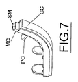
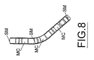
前記ログの搬送ユニット(LT)は、例えば、ガイド(GC)内に含まれかつボールジョイント(SM)によって一緒に結合されているメッシュ(MC)によって構成された3個のモータ駆動ループチェーンからなり、当該ガイド(GC)は所望の方向付けを有しそして作業中にログの背面と接触するように設定されるブレード(PC)が規則的な間隔で設けられている。 The log transport unit (LT) consists of, for example, three motor driven loop chains comprised of a mesh (MC) contained in a guide (GC) and joined together by a ball joint (SM). The guide (GC) has a desired orientation and is provided at regular intervals with blades (PC) set to contact the back of the log during operation.
実際上は、搬送ユニット(LT)はログ(L)に対する流れダイバータを形成し、この流れバイバータは前記巻き返し機からのログの流れを変えることができそしてまた前記巻き返し機に関してずれた位置において供給チャンネル(CT)を有する切断機械(CM)の設置を可能とする。 In practice, the transport unit (LT) forms a flow diverter for the log (L), which can change the flow of logs from the rewinder and also feed channels at offset positions with respect to the rewinder. Enables installation of a cutting machine (CM) having (CT).
図面に示したように、管形成機械(T)は巻き戻し機、エンボス―糊付けユニット及び巻き返し機によって形成される生産ラインの輪郭線内に位置している。 As shown in the drawings, the tube forming machine (T) is located within the outline of the production line formed by the unwinder, the embossing-gluing unit and the rewinder.
管形成機械(T)が、巻き戻し機、エンボス―糊付けユニット及び巻き返し機によって形成される生産ラインの外側に位置する従来のプラントと比較して、ログ生産プラントを建設する土地面積がかなり節約されている。例えば、ログの最大長さに等しい(2850.00mmに等しいログ長さ)場合、従って使用される同一の機械が使用される場合、従来のシステムにおいては、前記した寸法“A”は約20メートルの値をとる。 Compared to the conventional plant where the tube forming machine (T) is located outside the production line formed by the rewinder, embossing-gluing unit and rewinder, the land area to build the log production plant is considerably saved ing. For example, if the same length of log is used (the log length equal to 2850.00 mm), and therefore the same machine used is used, in the conventional system, the aforementioned dimension “A” is about 20 meters. Takes the value of
対照的に、前述したように、図1のダイアグラムにおけるように、前記管形成機械(T)を位置させること、即ち、前記巻き戻し機から前記巻き返し機へのペーパー(W)の通路を示す方向(PP)を遮るように前記管形成機械(T)を位置させることによって、前記寸法“A”はほとんど半分の値をとる。 In contrast, as described above, as in the diagram of FIG. 1, the tube forming machine (T) is positioned, ie, the direction indicating the path of the paper (W) from the unwinder to the unwinder. By positioning the tube forming machine (T) to block (PP) , the dimension “A” takes on almost half the value.
前記切断機械(CM)の上流側におけるログ(L)の蓄積は不要となり、前記搬送ユニット(LT)は切断機械(CM)を備えた巻き返し機(R)に直接接続しているのがわかる。 It can be seen that accumulation of the log (L) on the upstream side of the cutting machine (CM) is unnecessary, and the transport unit (LT) is directly connected to the rewinding machine (R) equipped with the cutting machine (CM).
前記管形成機械(T)は前記巻き返し機の下流側でかつ前記切断機械(CM)の上流側に設置するか又は前記巻き返し機の上流側に設置することが可能である。 The tube forming machine (T) can be installed downstream of the winder and upstream of the cutting machine (CM) or upstream of the winder.
実際上は、採用された解決手段から逸脱することなくかつ本特許によって付与された保護の範囲内に留まる限り、実施の詳細は記載されかつ図面に示された構成要素に関して如何なる均等の態様で変更することが可能である。 In practice, the implementation details have been changed in any equivalent manner with respect to the components described and shown in the drawings, without departing from the solutions employed and within the scope of protection conferred by this patent. Is possible.
A:輪郭線、寸法、B:所定量、寸法、C:コア、1C:第1の水平方向移動、2C:第2の水平方向移動、3C:第3の上り垂直移動、4C:第4の下り垂直移動、5C:第5の水平移動、6C:第6の水平移動、CC:予荷重(プレロード)チャンネル、CM:切断機械、CR:円筒状ロール、CS:第1アキュムレータ、CT:チャンネル、CV:縦方向コンベア、CW:ベルトコンベア、EG:エンボス−糊付けユニット、GC:ガイド、L:ログ、1L:第1上り垂直移動、2L:第2下り垂直移動、3L:第3水平移動、4L:第4水平移動、LD:偏移、LS:ログ用アキュムレータ、第2アキュムレータ、LT:搬送ユニット、コンベア、MC:メッシュ、PC:ブレード、PL:ログ支持バー、PP:方向、通路、R:巻き返し機、R1,R2:ペーパーリール、RO:ロール、SM:ボールジョイント、T:管形成機械、U1,U2:巻き戻し機、UP:巻き戻しステーション、V1,V2:ペーパープライ、W:ペーパーウエブ、ペーパー材料。 A: outline, dimension, B: predetermined amount, dimension, C: core, 1C: first horizontal movement, 2C: second horizontal movement, 3C: third upward vertical movement, 4C: fourth Downward vertical movement, 5C: Fifth horizontal movement, 6C: Sixth horizontal movement, CC: Preload channel, CM: Cutting machine, CR: Cylindrical roll, CS: First accumulator, CT: Channel, CV: Longitudinal conveyor, CW: Belt conveyor, EG: Emboss-gluing unit, GC: Guide, L: Log, 1L: First upward vertical movement, 2L: Second downward vertical movement, 3L: Third horizontal movement, 4L : 4th horizontal movement, LD: Deviation, LS: Log accumulator, 2nd accumulator, LT: Transfer unit, conveyor, MC: Mesh, PC: Blade, PL: Log support bar, PP: Direction, passage, R: roll Return machine, R1, R2: paper reel, RO: roll, SM: ball joint, T: tube forming machine, U1, U2: rewinding machine, UP: rewinding station, V1, V2: paper ply, W: paper web , Paper material.
Claims (16)
所定長さのロール(RO)を得るために前記ログ(L)を横方向に切断する工程とを含むペーパーロールの製造方法であって、
前記コア(C)が管形成機械(T)によって製造され、当該管形成機械が前記巻き返し機(R)に投入されるペーパーウエブ(W)の方向(PP)を遮る位置に設けられることを特徴とする製造方法。 By winding a predetermined amount of the paper web (W) around the tubular core (C) oriented transversely with respect to the direction (PP) of feeding the paper web (W) to the winding machine (R) where the winding is performed Manufacturing a log (L) of paper material;
A step of cutting the log (L) in a transverse direction to obtain a roll (RO) of a predetermined length,
The core (C) is manufactured by a pipe forming machine (T), and the pipe forming machine is provided at a position that blocks a direction (PP) of a paper web (W) to be fed into the rewinding machine (R). Manufacturing method.
かつ前記搬送する工程が横方向への偏移を含む通路に沿って前記ログ(L)を取り扱うことを含み、その結果、前記ログ(L)が進行するにつれて当該ログ(L)が前記横方向への偏移の影響を受けることを特徴とする請求項1記載の製造方法。 A step of conveying the log (L) from a rewinding machine (R) for manufacturing the log (L) toward a cutting machine (CM) for cutting the log (L) in a lateral direction,
And the conveying step includes handling the log (L) along a path including a lateral shift, so that as the log (L) progresses, the log (L) The manufacturing method according to claim 1, wherein the manufacturing method is affected by a shift toward
前記管形成機械(T)が巻き返し機(R)にペーパーウエブ(W)を投入する方向(PP)を遮る位置に設置されていることを特徴とするプラント。 A rewinding machine (R) for producing a log (L) of paper material (W) wound around a tubular core oriented transversely with respect to the direction (PP) of feeding the paper web (W) to the rewinding machine (R) And a tube forming machine (T) for producing the core (C), and a paper roll production plant comprising:
A plant characterized in that the tube forming machine (T) is installed at a position that blocks a direction (PP) of feeding a paper web (W) to a rewinding machine (R).
前記搬送ユニット(LT)が、ログが出口セクション方向に進行する間に当該ログに横方向の偏移を付加するために入口セクションと出口セクションの間に設けられた部分を含み、前記搬送ユニット(LT)の出口セクションが前記入口セクションに関して所定の値(B)だけ横方向にずれていることを特徴とするプラント。 A cutting machine (CM) that cuts the log (L) laterally to obtain a roll (RO) of a predetermined length, and the log (L) from the rewinder (R) toward the cutting machine (CM) A plant according to claim 8, comprising a transport unit (LT) provided for moving the transport, the transport unit (LT) comprising an inlet section and an outlet section for logs (L),
The transport unit (LT) includes a portion provided between an inlet section and an outlet section to add a lateral shift to the log while the log travels in the direction of the outlet section. LT) outlet section is offset laterally by a predetermined value (B) with respect to said inlet section.
前記管形成機械(T)が、前記方向(PP)に関して前記巻き返し機(R)の下流側でかつ前記切断機械(CM)の上流側に位置することを特徴とする請求項8記載のプラント。 In addition, including cutting machine (CM)
The plant according to claim 8, wherein the tube forming machine (T) is located downstream of the rewinder (R) and upstream of the cutting machine (CM) with respect to the direction (PP) .
Priority Applications (1)
| Application Number | Priority Date | Filing Date | Title |
|---|---|---|---|
| JP2018012732A JP6917916B2 (en) | 2014-12-20 | 2018-01-29 | Paper roll manufacturing method and plant |
Applications Claiming Priority (3)
| Application Number | Priority Date | Filing Date | Title |
|---|---|---|---|
| ITFI2014A000299 | 2014-12-20 | ||
| ITFI20140299 | 2014-12-20 | ||
| PCT/IT2015/000276 WO2016098135A1 (en) | 2014-12-20 | 2015-11-11 | Plant and process for the production of paper rolls |
Related Child Applications (1)
| Application Number | Title | Priority Date | Filing Date |
|---|---|---|---|
| JP2018012732A Division JP6917916B2 (en) | 2014-12-20 | 2018-01-29 | Paper roll manufacturing method and plant |
Publications (3)
| Publication Number | Publication Date |
|---|---|
| JP2017538643A JP2017538643A (en) | 2017-12-28 |
| JP2017538643A5 JP2017538643A5 (en) | 2019-04-04 |
| JP6570148B2 true JP6570148B2 (en) | 2019-09-04 |
Family
ID=52472395
Family Applications (3)
| Application Number | Title | Priority Date | Filing Date |
|---|---|---|---|
| JP2017532929A Active JP6570148B2 (en) | 2014-12-20 | 2015-11-11 | Paper roll manufacturing method and plant |
| JP2018012732A Active JP6917916B2 (en) | 2014-12-20 | 2018-01-29 | Paper roll manufacturing method and plant |
| JP2020046440A Active JP6959382B2 (en) | 2014-12-20 | 2020-03-17 | Paper roll manufacturing method and plant |
Family Applications After (2)
| Application Number | Title | Priority Date | Filing Date |
|---|---|---|---|
| JP2018012732A Active JP6917916B2 (en) | 2014-12-20 | 2018-01-29 | Paper roll manufacturing method and plant |
| JP2020046440A Active JP6959382B2 (en) | 2014-12-20 | 2020-03-17 | Paper roll manufacturing method and plant |
Country Status (11)
| Country | Link |
|---|---|
| US (2) | US10597246B2 (en) |
| EP (2) | EP3233680B1 (en) |
| JP (3) | JP6570148B2 (en) |
| CN (2) | CN108298354B (en) |
| BR (2) | BR112017011248B1 (en) |
| ES (2) | ES2893122T3 (en) |
| PL (2) | PL3233680T3 (en) |
| RS (2) | RS62536B1 (en) |
| RU (2) | RU2721801C2 (en) |
| TR (1) | TR201901621T4 (en) |
| WO (1) | WO2016098135A1 (en) |
Families Citing this family (4)
| Publication number | Priority date | Publication date | Assignee | Title |
|---|---|---|---|---|
| IT201800003969A1 (en) * | 2018-03-26 | 2019-09-26 | Perini Fabio Spa | METHOD FOR TAKING MEASUREMENTS ON ROLLS IN A PRODUCTION LINE AND PRODUCTION LINE FOR THE IMPLEMENTATION OF THE METHOD |
| CN108557144B (en) * | 2018-05-11 | 2023-08-18 | 张福明 | Packaging machine for imitation hand packaging of cashing paper by gold/silver film |
| IT201900018080A1 (en) * | 2019-10-07 | 2021-04-07 | Plusline S R L | Plant for the production and packaging of paper rolls. |
| CN117645138B (en) * | 2024-01-30 | 2024-04-05 | 泸州市一圣鸿包装有限公司 | Intelligent raw paper feeding system and method |
Family Cites Families (22)
| Publication number | Priority date | Publication date | Assignee | Title |
|---|---|---|---|---|
| US3762582A (en) | 1972-06-06 | 1973-10-02 | Procter & Gamble | Transfer and accumulating apparatus |
| US3926299A (en) | 1974-07-29 | 1975-12-16 | Paper Converting Machine Co | Method for storage of wound rolls of paper |
| FI82432C (en) * | 1988-02-22 | 1991-03-11 | Ahlstroem Valmet | BANRULLNINGSANORDNING. |
| IT1238717B (en) | 1990-04-27 | 1993-09-01 | Perini Navi Spa | REWINDING MACHINE WITH MEANS TO VARY THE NUMBER OF PERFORATIONS WRAPPED ON EACH TRAINING ROLL |
| JP3098880B2 (en) * | 1993-01-27 | 2000-10-16 | 株式会社石津製作所 | Roll paper manufacturing method |
| WO1994024033A1 (en) * | 1993-04-13 | 1994-10-27 | The Black Clawson Company | Continuous winder for web materials |
| US5556052A (en) * | 1993-07-23 | 1996-09-17 | Knaus; Dennis A. | Method and apparatus for winding |
| US5344091A (en) * | 1993-08-20 | 1994-09-06 | Elsner Engineering Works, Inc. | Apparatus for winding stiffened coreless rolls and method |
| US6715709B2 (en) | 2002-04-30 | 2004-04-06 | Kimberly-Clark Worldwide, Inc. | Apparatus and method for producing logs of sheet material |
| ITFI20020119A1 (en) * | 2002-07-08 | 2004-01-08 | Fabio Perini | REWINDING MACHINE AND METHOD FOR MANUFACTURING VARIOUS SIZE PAPER STICKS |
| ITFI20030066A1 (en) * | 2003-03-13 | 2004-09-14 | Perini Fabio Spa | CHAIN ACCUMULATOR DEVICE FOR PRODUCTS AND VEHICLES |
| ITFI20020154A1 (en) | 2002-08-09 | 2004-02-10 | Fabio Perini | MACHINE AND METHOD FOR PRODUCING CARDBOARD TUBES |
| ITFI20030312A1 (en) * | 2003-12-05 | 2005-06-06 | Perini Fabio Spa | METHOD AND MACHINE FOR THE PRODUCTION OF ROLLS OF RIBBED MATERIAL. |
| US7222813B2 (en) * | 2005-03-16 | 2007-05-29 | Chan Li Machinery Co., Ltd. | Multiprocessing apparatus for forming logs of web material and log manufacture process |
| DE102006012972B4 (en) * | 2006-03-21 | 2008-02-28 | Texmag Gmbh Vertriebsgesellschaft Gmbh | Device for controlling the lateral offset of webs of material |
| ITFI20060140A1 (en) * | 2006-06-09 | 2007-12-10 | Perini Fabio Spa | METHOD AND PE DEVICE PRODUCING ROLLS OF MATTRESS MATCHING WITH A MECHANISM OF INTERRUPTION OF THE RIBBED MATERIAL OPERATED BY THE TRANSIT OF THE WRAPPING ANIMALS. |
| JP2010063796A (en) * | 2008-09-12 | 2010-03-25 | Oji Nepia Co Ltd | Method for manufacturing sanitary paper roll |
| JP5331526B2 (en) * | 2009-03-18 | 2013-10-30 | 王子ネピア株式会社 | Manufacturing method of rolled sanitary paper |
| IT1397062B1 (en) * | 2009-12-29 | 2012-12-28 | Perini Fabio Spa | CUTTING MACHINE FOR CUTTING ROLLS OF RIBBED MATERIAL |
| IT1397711B1 (en) | 2010-01-22 | 2013-01-24 | Perini Fabio Spa | ACCUMULATION LUNG FOR TUBULAR WINDING ANIME. |
| CN103072840B (en) * | 2013-01-24 | 2015-09-30 | 金红叶纸业集团有限公司 | core pipe application recovery system, method and core pipe recovery system |
| JP6188194B2 (en) * | 2013-03-29 | 2017-08-30 | 大王製紙株式会社 | Toilet roll manufacturing method and toilet roll |
-
2015
- 2015-11-11 JP JP2017532929A patent/JP6570148B2/en active Active
- 2015-11-11 BR BR112017011248-5A patent/BR112017011248B1/en active IP Right Grant
- 2015-11-11 RU RU2017146665A patent/RU2721801C2/en active
- 2015-11-11 RS RS20211243A patent/RS62536B1/en unknown
- 2015-11-11 TR TR2019/01621T patent/TR201901621T4/en unknown
- 2015-11-11 EP EP15817580.2A patent/EP3233680B1/en active Active
- 2015-11-11 EP EP17020583.5A patent/EP3323759B1/en active Active
- 2015-11-11 ES ES17020583T patent/ES2893122T3/en active Active
- 2015-11-11 RU RU2017125929A patent/RU2679050C2/en active
- 2015-11-11 BR BR122018000115-1A patent/BR122018000115B1/en active IP Right Grant
- 2015-11-11 WO PCT/IT2015/000276 patent/WO2016098135A1/en active Application Filing
- 2015-11-11 ES ES15817580T patent/ES2707981T3/en active Active
- 2015-11-11 CN CN201810043226.8A patent/CN108298354B/en active Active
- 2015-11-11 RS RS20190163A patent/RS58318B1/en unknown
- 2015-11-11 PL PL15817580T patent/PL3233680T3/en unknown
- 2015-11-11 PL PL17020583T patent/PL3323759T3/en unknown
- 2015-11-11 CN CN201580069556.9A patent/CN107108141B/en active Active
- 2015-11-11 US US15/537,641 patent/US10597246B2/en active Active
-
2018
- 2018-01-29 JP JP2018012732A patent/JP6917916B2/en active Active
- 2018-02-14 US US15/896,376 patent/US10800627B2/en active Active
-
2020
- 2020-03-17 JP JP2020046440A patent/JP6959382B2/en active Active
Also Published As
Similar Documents
| Publication | Publication Date | Title |
|---|---|---|
| JP6959382B2 (en) | Paper roll manufacturing method and plant | |
| RU2567202C2 (en) | Rewinder and production of reels from roll material | |
| PL2041011T3 (en) | Robot for handling rolls | |
| JP2017538643A5 (en) | ||
| TW201309400A (en) | Device for transporting thin-layered web material of an amorphous material, arranged in several layers one over another | |
| EP2522608B1 (en) | Device for applying adhesive in a slitter-winder of fiber web machine | |
| EP2666739B1 (en) | Method of applying adhesive in a slitter-winder of fiber web machine | |
| ES2922350T3 (en) | Device for cutting a web of material into individual sheets with a web accumulator | |
| FI122538B (en) | Roller cutting machine for fiber web and method for longitudinal cutting of fiber web | |
| ITBO20070508A1 (en) | METHOD AND FEEDING SYSTEM OF TUBULAR SEMI-FINISHED PAPER SHEETS AT A ROLL CUTTING STATION. | |
| FI125686B (en) | Method and arrangement in connection with a fiber web roller cutter | |
| EP2664567B1 (en) | Method for web threading in a slitter-winder and a slitter-winder | |
| FI122980B (en) | Method and apparatus for winding fibrous webs, in particular paper and board | |
| CN102862847A (en) | Arrangement in a slitter-winder for a fiber web machine | |
| BR112014005574B1 (en) | method and system for forming spiral rolls |
Legal Events
| Date | Code | Title | Description |
|---|---|---|---|
| A521 | Request for written amendment filed |
Free format text: JAPANESE INTERMEDIATE CODE: A821 Effective date: 20170616 |
|
| A621 | Written request for application examination |
Free format text: JAPANESE INTERMEDIATE CODE: A621 Effective date: 20180319 |
|
| A977 | Report on retrieval |
Free format text: JAPANESE INTERMEDIATE CODE: A971007 Effective date: 20181119 |
|
| A131 | Notification of reasons for refusal |
Free format text: JAPANESE INTERMEDIATE CODE: A131 Effective date: 20181127 |
|
| A524 | Written submission of copy of amendment under article 19 pct |
Free format text: JAPANESE INTERMEDIATE CODE: A524 Effective date: 20190225 |
|
| TRDD | Decision of grant or rejection written | ||
| A01 | Written decision to grant a patent or to grant a registration (utility model) |
Free format text: JAPANESE INTERMEDIATE CODE: A01 Effective date: 20190726 |
|
| A61 | First payment of annual fees (during grant procedure) |
Free format text: JAPANESE INTERMEDIATE CODE: A61 Effective date: 20190802 |
|
| R150 | Certificate of patent or registration of utility model |
Ref document number: 6570148 Country of ref document: JP Free format text: JAPANESE INTERMEDIATE CODE: R150 |
|
| R250 | Receipt of annual fees |
Free format text: JAPANESE INTERMEDIATE CODE: R250 |
|
| R250 | Receipt of annual fees |
Free format text: JAPANESE INTERMEDIATE CODE: R250 |