EP3323759B1 - Plant and process for the production of paper rolls - Google Patents
Plant and process for the production of paper rolls Download PDFInfo
- Publication number
- EP3323759B1 EP3323759B1 EP17020583.5A EP17020583A EP3323759B1 EP 3323759 B1 EP3323759 B1 EP 3323759B1 EP 17020583 A EP17020583 A EP 17020583A EP 3323759 B1 EP3323759 B1 EP 3323759B1
- Authority
- EP
- European Patent Office
- Prior art keywords
- logs
- rewinder
- transport unit
- machine
- tube
- Prior art date
- Legal status (The legal status is an assumption and is not a legal conclusion. Google has not performed a legal analysis and makes no representation as to the accuracy of the status listed.)
- Active
Links
- 238000004519 manufacturing process Methods 0.000 title claims description 21
- 238000000034 method Methods 0.000 title description 7
- 230000008569 process Effects 0.000 title description 5
- 239000000123 paper Substances 0.000 claims description 28
- 238000011144 upstream manufacturing Methods 0.000 claims description 5
- 239000000463 material Substances 0.000 claims 1
- 230000032258 transport Effects 0.000 description 21
- 238000004513 sizing Methods 0.000 description 6
- 238000004026 adhesive bonding Methods 0.000 description 3
- 230000001174 ascending effect Effects 0.000 description 3
- 230000008901 benefit Effects 0.000 description 3
- 238000010586 diagram Methods 0.000 description 3
- 230000015572 biosynthetic process Effects 0.000 description 2
- 238000006073 displacement reaction Methods 0.000 description 2
- 238000004049 embossing Methods 0.000 description 2
- 239000003292 glue Substances 0.000 description 2
- 238000009434 installation Methods 0.000 description 2
- 230000009467 reduction Effects 0.000 description 2
- 238000004804 winding Methods 0.000 description 2
- 238000009825 accumulation Methods 0.000 description 1
- 230000008878 coupling Effects 0.000 description 1
- 238000010168 coupling process Methods 0.000 description 1
- 238000005859 coupling reaction Methods 0.000 description 1
- 238000005520 cutting process Methods 0.000 description 1
- 230000001419 dependent effect Effects 0.000 description 1
- 230000008021 deposition Effects 0.000 description 1
- 238000012986 modification Methods 0.000 description 1
- 230000004048 modification Effects 0.000 description 1
- 230000036316 preload Effects 0.000 description 1
- 230000002269 spontaneous effect Effects 0.000 description 1
- 238000003860 storage Methods 0.000 description 1
Images


Classifications
-
- B—PERFORMING OPERATIONS; TRANSPORTING
- B65—CONVEYING; PACKING; STORING; HANDLING THIN OR FILAMENTARY MATERIAL
- B65H—HANDLING THIN OR FILAMENTARY MATERIAL, e.g. SHEETS, WEBS, CABLES
- B65H19/00—Changing the web roll
- B65H19/22—Changing the web roll in winding mechanisms or in connection with winding operations
- B65H19/2238—The web roll being driven by a winding mechanism of the nip or tangential drive type
- B65H19/2269—Cradle
-
- B—PERFORMING OPERATIONS; TRANSPORTING
- B65—CONVEYING; PACKING; STORING; HANDLING THIN OR FILAMENTARY MATERIAL
- B65H—HANDLING THIN OR FILAMENTARY MATERIAL, e.g. SHEETS, WEBS, CABLES
- B65H18/00—Winding webs
-
- B—PERFORMING OPERATIONS; TRANSPORTING
- B65—CONVEYING; PACKING; STORING; HANDLING THIN OR FILAMENTARY MATERIAL
- B65H—HANDLING THIN OR FILAMENTARY MATERIAL, e.g. SHEETS, WEBS, CABLES
- B65H19/00—Changing the web roll
-
- B—PERFORMING OPERATIONS; TRANSPORTING
- B65—CONVEYING; PACKING; STORING; HANDLING THIN OR FILAMENTARY MATERIAL
- B65H—HANDLING THIN OR FILAMENTARY MATERIAL, e.g. SHEETS, WEBS, CABLES
- B65H2301/00—Handling processes for sheets or webs
- B65H2301/40—Type of handling process
- B65H2301/41—Winding, unwinding
- B65H2301/417—Handling or changing web rolls
- B65H2301/41704—Handling or changing web rolls involving layout of production or storage facility
Definitions
- the main purpose of the present invention is to propose a plant for the production of paper rolls allowing a remarkable reduction of the space required for the installation of the machines, without compromising the efficiency of the process or the quality of the finished product.
- a plant for the production of paper rolls typically comprises:
- the unwinders (U1, U2) allow the unwinding of the plies (V1, V2) from the reels (B1, B2). Said plies are embossed and glued in the station (EG) that produces the web (W) formed by the embossed and glued plies.
- the web feeds the rewinder (R) that provides for winding a predetermined amount thereof on each core (C) coming from the first accumulator (CS) and produced by the tube-forming machine (T).
- the core (C) allows the winding of the web (W) around an axis defined by the longitudinal axis of the same core (C).
- the logs thus produced in the rewinder (R) reach the conveyor (LT) which conveys them up to the second accumulator (LS).
- the latter feeds the cutting-off machine (CM) that cuts the logs to obtain rolls of the desired length.
- the tube-forming machine (T) and the cutting-off machine (CM) are oriented transversely to the path (PP) followed by the paper web. Therefore, the cores produced by the tube-forming machine (T) and exiting from the latter move along a direction substantially perpendicular to said path (PP) and the rolls produced by the cutting-off machine (CM) go out from the latter also in a direction substantially perpendicular to said path (PP).
- the first accumulator (CS) receives the cores produced by the tube-forming machine (T) by means of a vertical conveyor (VC).
- the unwinders (U1, U2), the embossing and sizing unit, the rewinder, the accumulator for the cores, the accumulator for the logs, the tube-forming machine, the means for transferring the cores from the tube-forming machine to the first accumulator, the means for transferring the logs from the second accumulator to the cutting-off machine, and the cutting-off machine can be of the type normally used for the production of paper rolls.
- EP0454633 and US6715709 disclose rewinders; WO2011/089634 discloses an accumulator for tubular cardboard cores; WO2004/014641 discloses a tube-forming machine; US3926299 and US3762582 disclose devices for handling and storage of paper logs.
- the tube-forming machine (T) is placed downstream of the rewinding machine (R) and is positioned on a platform (1) under which is arranged the transport unit for the logs (LT).
- the cutting-off machine (CM) is placed downstream of the second accumulator (LS). Since the transport unit (LT) imposes a lateral deviation to the logs while they move towards the second accumulator (LS), the cutting-off machine (CM) may be positioned within the outline "A" of the production line, that is, within line formed by the unwinders, the embossing-sizing unit, the rewinder, the first accumulator and the tube-forming machine.
- the transport unit of the logs (LT) when seen from above the transport unit of the logs (LT) can comprise a first rectilinear section, a second "S"-shaped section, and a third straight section. Otherwise, when seen from above the transport unit for the logs (LT) may include a "S"-shaped section preceded or followed by a straight section. Again, when seen from above the transport unit for the logs is rectilinear, oriented with a predetermined angle with respect to the above-mentioned path (PP). In any case, the output section of the transport unit for the logs (LT) is laterally displaced with respect to the centerline of the rewinder of a predetermined amount "B".
- the machines arrangement (in particular, the arrangement of the unwinders, the embossing-sizing unit, the rewinder, the accumulators and the cutting-off machine) is the same as in the previous case but the tube-forming machine (T) is on the same base of the other machines and the transport unit (LT) has an ascending section for passing over the tube-forming machine (T). Also in this case, the transport unit (LT) obliges the logs to deviate sideways while advancing towards the second accumulator (LS).
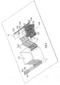
- Fig.4 and Fig.6 where the constructive details of the individual machines (in particular, the constructive details of the rewinder and the first and second accumulator) are not illustrated, it is shown the path of the cores (C) and the logs (L) in the area between the rewinder (R) and the tube-forming machine (T) .
- Fig.4 shows: a first horizontal translation (1C) of the cores leaving the tube-forming machine above the transport unit (LT); a second horizontal translation (2C) of the cores (C) when entering the first accumulator (CS), the second translation (2C) being orthogonal to the first (1C); a third ascending vertical movement (3C) of cores (C) in a stage prior to their exit from the first accumulator (CS); a fourth descending vertical movement (4C) of cores (C) when leaving the first accumulator; a fifth horizontal translation (5C) of cores (C) in the direction opposite to the first (1C); a sixth horizontal translation (6C) of cores (C) when they enter the rewinder (R); the transport unit (LT) that determines the advancement and the simultaneous lateral deviation of the logs (L).
- Fig.5 shows the overall path followed by cores (C).
- the translation (1C) is determined by the tube forming machine (T) that, while producing the cores (C), advances them, that is, forces them to move as shown in Fig.4 (arrow "1C").
- the translation (2C) is determined by the inlet section of the first accumulator (CS) which is normally provided with an input section that picks up the cores from the tube-forming machine (T).
- the cores are supported by shaped bars that move along a trajectory consisting of a succession of vertical and horizontal sections.
- the translation (3C) is the last run of the cores (C) within the first accumulator (CS).
- the translation (4C) takes place at the exit of the cores (C) from the first accumulator (CS) and ends with the deposition of the same cores on a belt conveyor (CW) that receives and transports the cores determining the fifth translation (5C).
- the sixth translation (6C) is determined by the fact that the conveyor (CW) is provided, in a per se known manner, of inclined cylindrical rollers (CR) that determine the sliding of the cores (C) towards the rewinder: actually, movements 5C and 6C are combined even if in the drawings they are represented as separated movements for the sake of clarity.
- Fig.6 where the constructive details of the individual machines (in particular, the constructive details of the rewinder, the second accumulator and the cutting-off machine) are not illustrated, it is shown the path of the logs (L) in the area between the rewinder (R) and the cutting-off machine (CM).
- Fig.6 shows, downstream of the transport unit (LT) that, as mentioned above, moves the log (L) along an advancing path comprising a lateral deviation: a first ascending vertical translation (1L) of logs (L) when entering the second accumulator (LS); a second descending vertical movement (2L) of logs (L) in a stage prior to their exit from the second accumulator (LS); a third horizontal translation (3L) of the logs (L) when exiting from the second accumulator (LS); a fourth horizontal translation (4L), orthogonal to the third (3L), of the logs in a step of advancing towards the blade of the cutting-off machine (CM).
- a first ascending vertical translation (1L) of logs (L) when entering the second accumulator (LS) a second descending vertical movement (2L) of logs (L) in a stage prior to their exit from the second accumulator (LS); a third horizontal translation (3L) of the logs (L) when exiting from the second accumulator (LS);
- the transport unit for the logs (LT) that makes the logs to deviate laterally while they advance towards the cutting-off machine (CM) allows to make use of conventional machines for making the plant and, at the same time, allows the positioning of the cutting-off machine (CM) and the tube-forming (T) within the outline of the production line arranged upstream and comprising the rewinder (R), the embossing-sizing unit (EG) and the unwinding unit (UP).
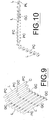
- the transport unit for the logs consists, for example, of three motor-driven loop chains constituted by meshes (MC) joined together by ball joints (SM), contained in guides (GC) having the desired orientation and equipped, at regular intervals, with blades (PC) that in operation are destined to be in contact with the back of the logs.
- MC meshes
- GC guides
- PC blades
- the transport unit (LT) forms a flow diverter for the logs (L), in the sense that it makes possible possible to divert the flow of logs exiting from the rewinder and place the cutting-off machine (CM) with its feeding channels (CT) also in an offset position with respect to the rewinder.
- CM cutting-off machine
- CT feeding channels
- the tube (T) as in the diagram of Fig.1 , that is, by placing the tube-forming machine (T) such that it is intercepted by the direction (PP) that represents the path of the paper (W) from the unwinders to the rewinder, the dimension "A" has a value almost halved. It is understood that, where the accumulation of the logs (L) upstream of the cutting-off machine (CM) is not required, the transport unit (LT) directly connects the rewinder (R) with the cutting-off machine (CM) .
- the tube-forming machine (T) can be placed downstream of the rewinder and upstream of the cutting-off machine, or upstream of the rewinder.
Description
- The present invention relates to a plant for the production of paper rolls. Such a plant is known from
US 2012/297944 A1 . It is known that the production of paper logs involves the feeding of a continuous paper web along a predefined path. At a preset point of said path, a transverse discontinuous cut is made on the paper to subdivide it into portions or sheets each having a predetermined length. This known technique involves the use of tubular cardboard elements, commonly said cores, on whose surface is distributed a predetermined amount of glue to allow the gluing of the first sheet of the log to be formed. This technique also provides for the use of winder rollers, positioned and acting in a logs forming station, which cause the rotation of the core on which the paper web is wound. The formation of a log is completed after that a predetermined amount of paper is wound on the core. At this point, another log is formed. At the end of the log formation process it is necessary to glue the last sheet of each log on the underlying one in order to avoid the spontaneous unwinding of the paper web. Cutting-off machines are subsequently used to subdivide each log into several rolls of smaller length to be packed. - Generally the production of paper rolls according to the scheme described above require that the tube-forming machines that produce the cores and the cutting-off machines are oriented transversely with respect to the path followed by the paper. This implies, however, the need for very large spaces and, therefore, high financial investments are required for the acquisition of the necessary spaces. Typically, a plant of the type described above, in fact occupies a very wide surface.
- The main purpose of the present invention is to propose a plant for the production of paper rolls allowing a remarkable reduction of the space required for the installation of the machines, without compromising the efficiency of the process or the quality of the finished product.
- This result is achieved in accordance with the present invention, by providing a system a plant having the features indicated in the independent claim. Other features of the present invention are the subject of the dependent claims.
- Among the main advantages offered by the present invention there is the fact that, by reducing the space required for the installation of the machines, less economic resources are required, which positively reflects also on the cost of the finished product. In addition, since the production cycle is changed only with reference to some operational phases, the plant can be managed also by personnel that normally operates the traditional systems. A further advantage is the relatively low cost of the modifications required to implement the present invention with respect to conventional plants and processes. Furthermore, in case of a plant comprising two or more production lines, given the lesser surface occupied by each line, the lines can be arranged closer to each other and the plant occupies a less extended area and therefore offers the possibility of using less operators , in particular a smaller number of plant managers or supervisors, compared to a conventional plant having the same number of production lines.
- These and other advantages and features of the present invention will be best understood by anyone skilled in the art thanks to the following description and to the attached drawings, provided by way of example but not to be considered in a limitative sense, wherein:
-
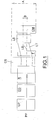
Fig.1 is a schematic top view of a plant in accordance with the present invention; -
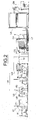
Fig.2 is a schematic side view of the plant shown inFig.1 ; -
Fig.3 is a view similar to that ofFig.2 but it refers to a further embodiment of the plant; -
Fig.4 shows the path of the cores and the logs in the area between the rewinder and the tube forming machine; -
Fig.5 is a diagram showing the movements of the cores in the area between the rewinder and the tube forming machine; -
Fig.6 shows the path of the logs and the cut rolls in the area between the accumulator for the logs and the cutting-off machine; -
Figs. 7-9 schematically represent a part of the logs transport unit (LT); -
Fig.10 is an enlarged detail ofFig.3 . - Reduced to its basic structure and with reference to the attached drawings, a plant for the production of paper rolls (for example, rolls of toilet paper or rolls of kitchen paper) in accordance with the present invention typically comprises:
- a paper unwinding station (UP) with one or more unwinders (in the example, the unwinders are two in number and are indicated by references "U1" and "U2") that support a corresponding number of paper reels (R1, R2) from each of which a paper ply (V1, V2) unwounds;
- a unit (EG) for coupling of the paper plies coming from the unwinding station (UP), with an embossing and gluing unit in which said plies can be be embossed and joined together by gluing to form a two-plies paper web (W) ;
- a rewinder (R) which on side receives the paper web (W) and on another side receives the tubular cores on which the paper web is wound to form the logs (L);
- a tube-forming machine (T) that produces the tubular cores;
- a first accumulator (CS), which receives and accumulates the cores produced by the tube-forming machine (T) and feeds the rewinder (R);
- a second accumulator (LS) which receives the logs produced by the rewinder (R);
- a transport unit (LT) which receives the logs outgoing from the rewinder (R) and transports them to the second accumulator (LS);
- a cutting-off machine (CM) which receives the logs coming from the second accumulator (LS) and subdivides them into rolls of lesser length.
- The unwinders (U1, U2) allow the unwinding of the plies (V1, V2) from the reels (B1, B2). Said plies are embossed and glued in the station (EG) that produces the web (W) formed by the embossed and glued plies. The web feeds the rewinder (R) that provides for winding a predetermined amount thereof on each core (C) coming from the first accumulator (CS) and produced by the tube-forming machine (T). The core (C) allows the winding of the web (W) around an axis defined by the longitudinal axis of the same core (C). The logs thus produced in the rewinder (R) reach the conveyor (LT) which conveys them up to the second accumulator (LS). The latter feeds the cutting-off machine (CM) that cuts the logs to obtain rolls of the desired length.
- The tube-forming machine (T) and the cutting-off machine (CM) are oriented transversely to the path (PP) followed by the paper web. Therefore, the cores produced by the tube-forming machine (T) and exiting from the latter move along a direction substantially perpendicular to said path (PP) and the rolls produced by the cutting-off machine (CM) go out from the latter also in a direction substantially perpendicular to said path (PP).
- The first accumulator (CS) receives the cores produced by the tube-forming machine (T) by means of a vertical conveyor (VC).
- The unwinders (U1, U2), the embossing and sizing unit, the rewinder, the accumulator for the cores, the accumulator for the logs, the tube-forming machine, the means for transferring the cores from the tube-forming machine to the first accumulator, the means for transferring the logs from the second accumulator to the cutting-off machine, and the cutting-off machine can be of the type normally used for the production of paper rolls.
EP0454633 andUS6715709 disclose rewinders;WO2011/089634 discloses an accumulator for tubular cardboard cores;WO2004/014641 discloses a tube-forming machine;US3926299 andUS3762582 disclose devices for handling and storage of paper logs. - According to the example shown in
Fig.2 , the tube-forming machine (T) is placed downstream of the rewinding machine (R) and is positioned on a platform (1) under which is arranged the transport unit for the logs (LT). The cutting-off machine (CM) is placed downstream of the second accumulator (LS). Since the transport unit (LT) imposes a lateral deviation to the logs while they move towards the second accumulator (LS), the cutting-off machine (CM) may be positioned within the outline "A" of the production line, that is, within line formed by the unwinders, the embossing-sizing unit, the rewinder, the first accumulator and the tube-forming machine. In the example, the transport unit (LT) determines a deviation (LD) of the logs to the left while the logs advance along the path comprised between the rewinder (R) and the second accumulator (LS). Thanks to the lateral deviation imposed to the logs that move towards the second accumulator (LS), the cutting-off machine (CM) can be arranged as described above and this reduces the overall width of the production line compared to the traditional plants that provide for a straight advancement of the logs between the rewinder and the accumulator for the logs. When seen from above, according to the example shown in the drawings, the transport unit for the logs (LT) is "S"-shaped. It is understood that, if required, when seen from above the transport unit of the logs (LT) can comprise a first rectilinear section, a second "S"-shaped section, and a third straight section. Otherwise, when seen from above the transport unit for the logs (LT) may include a "S"-shaped section preceded or followed by a straight section. Again, when seen from above the transport unit for the logs is rectilinear, oriented with a predetermined angle with respect to the above-mentioned path (PP). In any case, the output section of the transport unit for the logs (LT) is laterally displaced with respect to the centerline of the rewinder of a predetermined amount "B". - It is observed that with the current production requirements, characterized by high operating speeds (production rate of at least 60 logs per minute), the lateral displacement of the logs (not combined with the advancement) would require a conveyor surface with an extremely high friction coefficient which, however, implies damages to the surface of the logs. In the past, such a solution has been adopted but for lower production rates (about 20 logs per minute). The combination of the advancement and the lateral displacement of the logs implies a lower speed lateral component without imposing any reduction of the operating speeds.
- Referring to the diagram of
Figure 1 , in an experimental facility built by the applicant's the dimension "A" was about 12.00 (twelve) meters and dimension "B" was 2.265 (two-point-two-hundred-sixtyfive) meters. The experimental plant was intended to produce logs having a maximum size of 2850 mm. - With reference to the example shown in
Fig.3 , the machines arrangement (in particular, the arrangement of the unwinders, the embossing-sizing unit, the rewinder, the accumulators and the cutting-off machine) is the same as in the previous case but the tube-forming machine (T) is on the same base of the other machines and the transport unit (LT) has an ascending section for passing over the tube-forming machine (T). Also in this case, the transport unit (LT) obliges the logs to deviate sideways while advancing towards the second accumulator (LS). - In
Fig.4 andFig.6 , where the constructive details of the individual machines (in particular, the constructive details of the rewinder and the first and second accumulator) are not illustrated, it is shown the path of the cores (C) and the logs (L) in the area between the rewinder (R) and the tube-forming machine (T) . - In particular,
Fig.4 shows: a first horizontal translation (1C) of the cores leaving the tube-forming machine above the transport unit (LT); a second horizontal translation (2C) of the cores (C) when entering the first accumulator (CS), the second translation (2C) being orthogonal to the first (1C); a third ascending vertical movement (3C) of cores (C) in a stage prior to their exit from the first accumulator (CS); a fourth descending vertical movement (4C) of cores (C) when leaving the first accumulator; a fifth horizontal translation (5C) of cores (C) in the direction opposite to the first (1C); a sixth horizontal translation (6C) of cores (C) when they enter the rewinder (R); the transport unit (LT) that determines the advancement and the simultaneous lateral deviation of the logs (L).Fig.5 shows the overall path followed by cores (C). - The translation (1C) is determined by the tube forming machine (T) that, while producing the cores (C), advances them, that is, forces them to move as shown in
Fig.4 (arrow "1C"). The translation (2C) is determined by the inlet section of the first accumulator (CS) which is normally provided with an input section that picks up the cores from the tube-forming machine (T). Within the first accumulator (CS), the cores are supported by shaped bars that move along a trajectory consisting of a succession of vertical and horizontal sections. The translation (3C) is the last run of the cores (C) within the first accumulator (CS). The translation (4C) takes place at the exit of the cores (C) from the first accumulator (CS) and ends with the deposition of the same cores on a belt conveyor (CW) that receives and transports the cores determining the fifth translation (5C). The sixth translation (6C) is determined by the fact that the conveyor (CW) is provided, in a per se known manner, of inclined cylindrical rollers (CR) that determine the sliding of the cores (C) towards the rewinder: actually,movements - In
Fig.6 , where the constructive details of the individual machines (in particular, the constructive details of the rewinder, the second accumulator and the cutting-off machine) are not illustrated, it is shown the path of the logs (L) in the area between the rewinder (R) and the cutting-off machine (CM). - In particular,
Fig.6 shows, downstream of the transport unit (LT) that, as mentioned above, moves the log (L) along an advancing path comprising a lateral deviation: a first ascending vertical translation (1L) of logs (L) when entering the second accumulator (LS); a second descending vertical movement (2L) of logs (L) in a stage prior to their exit from the second accumulator (LS); a third horizontal translation (3L) of the logs (L) when exiting from the second accumulator (LS); a fourth horizontal translation (4L), orthogonal to the third (3L), of the logs in a step of advancing towards the blade of the cutting-off machine (CM). InFigure 6 the rolls produced by the cutting of the log (L) by means of the cutting-off machine (CM) are denoted by reference "RO". Inside the second accumulator (LS), the logs (L) are supported by shaped bars that move along a trajectory consisting of a succession of vertical and horizontal sections. In its terminal part (part facing the cutting-off machine), the second accumulator (LS), that can be of the known type comprising a series of log-supporting bars (PL) moved by chains, extends horizontally above the channels (CT) on which the logs normally slide when entering the cutting-off machine. Between the log-supporting bars (PL) and the channels (CT) are interposed corresponding so-called pre-load channels (CC) that receive the logs from the log-supporting bars of the accumulator (LS) and discharge them onto the channels (CT) of the cutting-off machine in synchronism with the pushers acting on the logs in the cutting-off machine according to a process known per se. - The transport unit for the logs (LT) that makes the logs to deviate laterally while they advance towards the cutting-off machine (CM) allows to make use of conventional machines for making the plant and, at the same time, allows the positioning of the cutting-off machine (CM) and the tube-forming (T) within the outline of the production line arranged upstream and comprising the rewinder (R), the embossing-sizing unit (EG) and the unwinding unit (UP).
- The transport unit for the logs (LT) consists, for example, of three motor-driven loop chains constituted by meshes (MC) joined together by ball joints (SM), contained in guides (GC) having the desired orientation and equipped, at regular intervals, with blades (PC) that in operation are destined to be in contact with the back of the logs.
- In practice, the transport unit (LT) forms a flow diverter for the logs (L), in the sense that it makes possible possible to divert the flow of logs exiting from the rewinder and place the cutting-off machine (CM) with its feeding channels (CT) also in an offset position with respect to the rewinder.
- As shown in the drawings, the tube-forming machine (T) is located within the outline of the production line formed by the unwinders, the embossing-sizing unit and the rewinder.
- Compared to a conventional plant, in which the tube-forming machine (T) is external to the production line formed by the unwinders, the embossing-sizing unit and the rewinder, there is a considerable saving of ground area in manufacturing the logs production plant. For example, for equal maximum size of the logs (logs length equal to 2850.00 mm) and hence the same machines used, in a traditional system the dimension "A" previously mentioned assumes a value of about 20 meters. By contrast, as mentioned earlier, positioning the tube (T) as in the diagram of
Fig.1 , that is, by placing the tube-forming machine (T) such that it is intercepted by the direction (PP) that represents the path of the paper (W) from the unwinders to the rewinder, the dimension "A" has a value almost halved. It is understood that, where the accumulation of the logs (L) upstream of the cutting-off machine (CM) is not required, the transport unit (LT) directly connects the rewinder (R) with the cutting-off machine (CM) . - The tube-forming machine (T) can be placed downstream of the rewinder and upstream of the cutting-off machine, or upstream of the rewinder.
Claims (6)
- Plant for the production of rolls of paper, comprising a rewinder (R) that produces logs (L) of paper material, a cutting-off machine (CM) that cuts the logs (L) transversely to obtain rolls (RO) of predefined length, and a transport unit (LT) arranged to move the logs (L) from the rewinder (R) toward the cutting-off machine (CM), wherein said transport unit (LT) comprises an inlet section and an outlet section for the logs (L), characterized in that said transport unit (LT) comprises a part between said logs input and output sections adapted to impose a lateral deviation to the same logs while they advance towards the outlet section, the output section of the transport unit (LT) being laterally offset by a predetermined value (B) with respect to the input section, the plant comprising a tube-forming machine (T) adapted to produce cardboard tubes each of which constitutes an internal core (C) of a respective log (L), the tube-forming machine (T) being located at a position that is intercepted by the direction (PP) that represents the path of the paper (W) from the unwinder to the rewinder.
- Plant according to claim 1, characterized in that, seen in plan view, said transport unit log (L) comprises a "S"-shaped part.
- Plant according to claims 1 and 2 characterized in that said logs transport unit (LT) comprises a part that passes beneath the tube-forming machine (T) which produces the cores (C).
- Plant according to claims 1 and 2 characterized in that said logs transport unit (LT) comprises a part that passes over the tube-forming machine (T) which produces the cores (C).
- Plant according to any of claims 1 to 4 characterized in that it comprises an accumulator for logs (LS) upstream of the cutting-off machine (CM), so that said logs transport unit is positioned between the rewinder (R) and the accumulator for logs (LS) and the latter supplies the cutting-off machine (CM).
- Plant according to any of claims 1 to 5, characterized in that the tube-forming machine (T) is located downstream of the rewinder (R) with respect to the path (PP) followed by the paper web (W) entering the same rewinder (R).
Priority Applications (2)
| Application Number | Priority Date | Filing Date | Title |
|---|---|---|---|
| PL17020583T PL3323759T3 (en) | 2014-12-20 | 2015-11-11 | Plant and process for the production of paper rolls |
| RS20211243A RS62536B1 (en) | 2014-12-20 | 2015-11-11 | Plant and process for the production of paper rolls |
Applications Claiming Priority (3)
| Application Number | Priority Date | Filing Date | Title |
|---|---|---|---|
| ITFI20140299 | 2014-12-20 | ||
| PCT/IT2015/000276 WO2016098135A1 (en) | 2014-12-20 | 2015-11-11 | Plant and process for the production of paper rolls |
| EP15817580.2A EP3233680B1 (en) | 2014-12-20 | 2015-11-11 | Plant and process for the production of paper rolls |
Related Parent Applications (2)
| Application Number | Title | Priority Date | Filing Date |
|---|---|---|---|
| EP15817580.2A Division EP3233680B1 (en) | 2014-12-20 | 2015-11-11 | Plant and process for the production of paper rolls |
| EP15817580.2A Division-Into EP3233680B1 (en) | 2014-12-20 | 2015-11-11 | Plant and process for the production of paper rolls |
Publications (2)
| Publication Number | Publication Date |
|---|---|
| EP3323759A1 EP3323759A1 (en) | 2018-05-23 |
| EP3323759B1 true EP3323759B1 (en) | 2021-08-25 |
Family
ID=52472395
Family Applications (2)
| Application Number | Title | Priority Date | Filing Date |
|---|---|---|---|
| EP17020583.5A Active EP3323759B1 (en) | 2014-12-20 | 2015-11-11 | Plant and process for the production of paper rolls |
| EP15817580.2A Active EP3233680B1 (en) | 2014-12-20 | 2015-11-11 | Plant and process for the production of paper rolls |
Family Applications After (1)
| Application Number | Title | Priority Date | Filing Date |
|---|---|---|---|
| EP15817580.2A Active EP3233680B1 (en) | 2014-12-20 | 2015-11-11 | Plant and process for the production of paper rolls |
Country Status (11)
| Country | Link |
|---|---|
| US (2) | US10597246B2 (en) |
| EP (2) | EP3323759B1 (en) |
| JP (3) | JP6570148B2 (en) |
| CN (2) | CN107108141B (en) |
| BR (2) | BR122018000115B1 (en) |
| ES (2) | ES2707981T3 (en) |
| PL (2) | PL3323759T3 (en) |
| RS (2) | RS58318B1 (en) |
| RU (2) | RU2679050C2 (en) |
| TR (1) | TR201901621T4 (en) |
| WO (1) | WO2016098135A1 (en) |
Families Citing this family (4)
| Publication number | Priority date | Publication date | Assignee | Title |
|---|---|---|---|---|
| IT201800003969A1 (en) * | 2018-03-26 | 2019-09-26 | Perini Fabio Spa | METHOD FOR TAKING MEASUREMENTS ON ROLLS IN A PRODUCTION LINE AND PRODUCTION LINE FOR THE IMPLEMENTATION OF THE METHOD |
| CN108557144B (en) * | 2018-05-11 | 2023-08-18 | 张福明 | Packaging machine for imitation hand packaging of cashing paper by gold/silver film |
| IT201900018080A1 (en) * | 2019-10-07 | 2021-04-07 | Plusline S R L | Plant for the production and packaging of paper rolls. |
| CN117645138B (en) * | 2024-01-30 | 2024-04-05 | 泸州市一圣鸿包装有限公司 | Intelligent raw paper feeding system and method |
Family Cites Families (22)
| Publication number | Priority date | Publication date | Assignee | Title |
|---|---|---|---|---|
| US3762582A (en) | 1972-06-06 | 1973-10-02 | Procter & Gamble | Transfer and accumulating apparatus |
| US3926299A (en) | 1974-07-29 | 1975-12-16 | Paper Converting Machine Co | Method for storage of wound rolls of paper |
| FI82432C (en) * | 1988-02-22 | 1991-03-11 | Ahlstroem Valmet | BANRULLNINGSANORDNING. |
| IT1238717B (en) | 1990-04-27 | 1993-09-01 | Perini Navi Spa | REWINDING MACHINE WITH MEANS TO VARY THE NUMBER OF PERFORATIONS WRAPPED ON EACH TRAINING ROLL |
| JP3098880B2 (en) * | 1993-01-27 | 2000-10-16 | 株式会社石津製作所 | Roll paper manufacturing method |
| WO1994024033A1 (en) * | 1993-04-13 | 1994-10-27 | The Black Clawson Company | Continuous winder for web materials |
| US5556052A (en) * | 1993-07-23 | 1996-09-17 | Knaus; Dennis A. | Method and apparatus for winding |
| US5344091A (en) * | 1993-08-20 | 1994-09-06 | Elsner Engineering Works, Inc. | Apparatus for winding stiffened coreless rolls and method |
| US6715709B2 (en) | 2002-04-30 | 2004-04-06 | Kimberly-Clark Worldwide, Inc. | Apparatus and method for producing logs of sheet material |
| ITFI20020119A1 (en) * | 2002-07-08 | 2004-01-08 | Fabio Perini | REWINDING MACHINE AND METHOD FOR MANUFACTURING VARIOUS SIZE PAPER STICKS |
| ITFI20030066A1 (en) | 2003-03-13 | 2004-09-14 | Perini Fabio Spa | CHAIN ACCUMULATOR DEVICE FOR PRODUCTS AND VEHICLES |
| ITFI20020154A1 (en) | 2002-08-09 | 2004-02-10 | Fabio Perini | MACHINE AND METHOD FOR PRODUCING CARDBOARD TUBES |
| ITFI20030312A1 (en) * | 2003-12-05 | 2005-06-06 | Perini Fabio Spa | METHOD AND MACHINE FOR THE PRODUCTION OF ROLLS OF RIBBED MATERIAL. |
| US7222813B2 (en) * | 2005-03-16 | 2007-05-29 | Chan Li Machinery Co., Ltd. | Multiprocessing apparatus for forming logs of web material and log manufacture process |
| DE102006012972B4 (en) * | 2006-03-21 | 2008-02-28 | Texmag Gmbh Vertriebsgesellschaft Gmbh | Device for controlling the lateral offset of webs of material |
| ITFI20060140A1 (en) * | 2006-06-09 | 2007-12-10 | Perini Fabio Spa | METHOD AND PE DEVICE PRODUCING ROLLS OF MATTRESS MATCHING WITH A MECHANISM OF INTERRUPTION OF THE RIBBED MATERIAL OPERATED BY THE TRANSIT OF THE WRAPPING ANIMALS. |
| JP2010063796A (en) * | 2008-09-12 | 2010-03-25 | Oji Nepia Co Ltd | Method for manufacturing sanitary paper roll |
| JP5331526B2 (en) * | 2009-03-18 | 2013-10-30 | 王子ネピア株式会社 | Manufacturing method of rolled sanitary paper |
| IT1397062B1 (en) * | 2009-12-29 | 2012-12-28 | Perini Fabio Spa | CUTTING MACHINE FOR CUTTING ROLLS OF RIBBED MATERIAL |
| IT1397711B1 (en) | 2010-01-22 | 2013-01-24 | Perini Fabio Spa | ACCUMULATION LUNG FOR TUBULAR WINDING ANIME. |
| CN103072840B (en) * | 2013-01-24 | 2015-09-30 | 金红叶纸业集团有限公司 | core pipe application recovery system, method and core pipe recovery system |
| JP6188194B2 (en) * | 2013-03-29 | 2017-08-30 | 大王製紙株式会社 | Toilet roll manufacturing method and toilet roll |
-
2015
- 2015-11-11 RS RS20190163A patent/RS58318B1/en unknown
- 2015-11-11 PL PL17020583T patent/PL3323759T3/en unknown
- 2015-11-11 RU RU2017125929A patent/RU2679050C2/en active
- 2015-11-11 RS RS20211243A patent/RS62536B1/en unknown
- 2015-11-11 RU RU2017146665A patent/RU2721801C2/en active
- 2015-11-11 EP EP17020583.5A patent/EP3323759B1/en active Active
- 2015-11-11 ES ES15817580T patent/ES2707981T3/en active Active
- 2015-11-11 BR BR122018000115-1A patent/BR122018000115B1/en active IP Right Grant
- 2015-11-11 CN CN201580069556.9A patent/CN107108141B/en active Active
- 2015-11-11 US US15/537,641 patent/US10597246B2/en active Active
- 2015-11-11 ES ES17020583T patent/ES2893122T3/en active Active
- 2015-11-11 PL PL15817580T patent/PL3233680T3/en unknown
- 2015-11-11 TR TR2019/01621T patent/TR201901621T4/en unknown
- 2015-11-11 EP EP15817580.2A patent/EP3233680B1/en active Active
- 2015-11-11 CN CN201810043226.8A patent/CN108298354B/en active Active
- 2015-11-11 JP JP2017532929A patent/JP6570148B2/en active Active
- 2015-11-11 WO PCT/IT2015/000276 patent/WO2016098135A1/en active Application Filing
- 2015-11-11 BR BR112017011248-5A patent/BR112017011248B1/en active IP Right Grant
-
2018
- 2018-01-29 JP JP2018012732A patent/JP6917916B2/en active Active
- 2018-02-14 US US15/896,376 patent/US10800627B2/en active Active
-
2020
- 2020-03-17 JP JP2020046440A patent/JP6959382B2/en active Active
Non-Patent Citations (1)
| Title |
|---|
| None * |
Also Published As
Similar Documents
| Publication | Publication Date | Title |
|---|---|---|
| US10800627B2 (en) | Plant and process for the production of paper rolls | |
| CN101505930B (en) | Machine for cutting paper logs | |
| EP3632226B1 (en) | Assembly method for producing cigarettes | |
| CA2294227A1 (en) | Slitter rewinder machine for producing reels of weblike material and associated method | |
| EP2916668B1 (en) | Cigarette manufacturing assembly machine, and relative assembly method | |
| EP3099481B1 (en) | Equipment and method for the production of cardboard tubes | |
| JP2017538643A5 (en) | ||
| CN202558346U (en) | Wide coiled material dividing and cutting device | |
| CN103213867A (en) | Slitting device and slitting method of wide coiling material | |
| EP2669223B1 (en) | Method for winding fiber webs and device in a winder for winding fiber webs, especially for partial paper and board webs | |
| EP1842815A1 (en) | Installation for paper production | |
| CN202704672U (en) | Slitting device for wide coiled material | |
| CN113428704B (en) | Winding process for high-speed operation reel change | |
| CN111573176B (en) | Reel transport rail system and method for transporting reels thereon | |
| CN202148073U (en) | Paper feed stabilizing system | |
| CN102862847A (en) | Arrangement in a slitter-winder for a fiber web machine | |
| WO2012056095A1 (en) | Method and device for winding of fiber webs, especially of paper and board webs |
Legal Events
| Date | Code | Title | Description |
|---|---|---|---|
| PUAI | Public reference made under article 153(3) epc to a published international application that has entered the european phase |
Free format text: ORIGINAL CODE: 0009012 |
|
| STAA | Information on the status of an ep patent application or granted ep patent |
Free format text: STATUS: THE APPLICATION HAS BEEN PUBLISHED |
|
| AC | Divisional application: reference to earlier application |
Ref document number: 3233680 Country of ref document: EP Kind code of ref document: P |
|
| AK | Designated contracting states |
Kind code of ref document: A1 Designated state(s): AL AT BE BG CH CY CZ DE DK EE ES FI FR GB GR HR HU IE IS IT LI LT LU LV MC MK MT NL NO PL PT RO RS SE SI SK SM TR |
|
| STAA | Information on the status of an ep patent application or granted ep patent |
Free format text: STATUS: REQUEST FOR EXAMINATION WAS MADE |
|
| 17P | Request for examination filed |
Effective date: 20181117 |
|
| RBV | Designated contracting states (corrected) |
Designated state(s): AL AT BE BG CH CY CZ DE DK EE ES FI FR GB GR HR HU IE IS IT LI LT LU LV MC MK MT NL NO PL PT RO RS SE SI SK SM TR |
|
| STAA | Information on the status of an ep patent application or granted ep patent |
Free format text: STATUS: EXAMINATION IS IN PROGRESS |
|
| 17Q | First examination report despatched |
Effective date: 20200403 |
|
| STAA | Information on the status of an ep patent application or granted ep patent |
Free format text: STATUS: EXAMINATION IS IN PROGRESS |
|
| GRAP | Despatch of communication of intention to grant a patent |
Free format text: ORIGINAL CODE: EPIDOSNIGR1 |
|
| STAA | Information on the status of an ep patent application or granted ep patent |
Free format text: STATUS: GRANT OF PATENT IS INTENDED |
|
| INTG | Intention to grant announced |
Effective date: 20210519 |
|
| GRAS | Grant fee paid |
Free format text: ORIGINAL CODE: EPIDOSNIGR3 |
|
| GRAA | (expected) grant |
Free format text: ORIGINAL CODE: 0009210 |
|
| STAA | Information on the status of an ep patent application or granted ep patent |
Free format text: STATUS: THE PATENT HAS BEEN GRANTED |
|
| AC | Divisional application: reference to earlier application |
Ref document number: 3233680 Country of ref document: EP Kind code of ref document: P |
|
| AK | Designated contracting states |
Kind code of ref document: B1 Designated state(s): AL AT BE BG CH CY CZ DE DK EE ES FI FR GB GR HR HU IE IS IT LI LT LU LV MC MK MT NL NO PL PT RO RS SE SI SK SM TR |
|
| REG | Reference to a national code |
Ref country code: CH Ref legal event code: EP |
|
| REG | Reference to a national code |
Ref country code: IE Ref legal event code: FG4D Ref country code: AT Ref legal event code: REF Ref document number: 1423593 Country of ref document: AT Kind code of ref document: T Effective date: 20210915 |
|
| REG | Reference to a national code |
Ref country code: DE Ref legal event code: R096 Ref document number: 602015072775 Country of ref document: DE |
|
| REG | Reference to a national code |
Ref country code: FI Ref legal event code: FGE |
|
| REG | Reference to a national code |
Ref country code: SE Ref legal event code: TRGR |
|
| REG | Reference to a national code |
Ref country code: LT Ref legal event code: MG9D |
|
| REG | Reference to a national code |
Ref country code: NL Ref legal event code: MP Effective date: 20210825 |
|
| REG | Reference to a national code |
Ref country code: AT Ref legal event code: MK05 Ref document number: 1423593 Country of ref document: AT Kind code of ref document: T Effective date: 20210825 |
|
| PG25 | Lapsed in a contracting state [announced via postgrant information from national office to epo] |
Ref country code: LT Free format text: LAPSE BECAUSE OF FAILURE TO SUBMIT A TRANSLATION OF THE DESCRIPTION OR TO PAY THE FEE WITHIN THE PRESCRIBED TIME-LIMIT Effective date: 20210825 Ref country code: AT Free format text: LAPSE BECAUSE OF FAILURE TO SUBMIT A TRANSLATION OF THE DESCRIPTION OR TO PAY THE FEE WITHIN THE PRESCRIBED TIME-LIMIT Effective date: 20210825 Ref country code: BG Free format text: LAPSE BECAUSE OF FAILURE TO SUBMIT A TRANSLATION OF THE DESCRIPTION OR TO PAY THE FEE WITHIN THE PRESCRIBED TIME-LIMIT Effective date: 20211125 Ref country code: HR Free format text: LAPSE BECAUSE OF FAILURE TO SUBMIT A TRANSLATION OF THE DESCRIPTION OR TO PAY THE FEE WITHIN THE PRESCRIBED TIME-LIMIT Effective date: 20210825 Ref country code: NO Free format text: LAPSE BECAUSE OF FAILURE TO SUBMIT A TRANSLATION OF THE DESCRIPTION OR TO PAY THE FEE WITHIN THE PRESCRIBED TIME-LIMIT Effective date: 20211125 Ref country code: PT Free format text: LAPSE BECAUSE OF FAILURE TO SUBMIT A TRANSLATION OF THE DESCRIPTION OR TO PAY THE FEE WITHIN THE PRESCRIBED TIME-LIMIT Effective date: 20211227 |
|
| REG | Reference to a national code |
Ref country code: ES Ref legal event code: FG2A Ref document number: 2893122 Country of ref document: ES Kind code of ref document: T3 Effective date: 20220208 |
|
| PG25 | Lapsed in a contracting state [announced via postgrant information from national office to epo] |
Ref country code: LV Free format text: LAPSE BECAUSE OF FAILURE TO SUBMIT A TRANSLATION OF THE DESCRIPTION OR TO PAY THE FEE WITHIN THE PRESCRIBED TIME-LIMIT Effective date: 20210825 Ref country code: GR Free format text: LAPSE BECAUSE OF FAILURE TO SUBMIT A TRANSLATION OF THE DESCRIPTION OR TO PAY THE FEE WITHIN THE PRESCRIBED TIME-LIMIT Effective date: 20211126 |
|
| PG25 | Lapsed in a contracting state [announced via postgrant information from national office to epo] |
Ref country code: NL Free format text: LAPSE BECAUSE OF FAILURE TO SUBMIT A TRANSLATION OF THE DESCRIPTION OR TO PAY THE FEE WITHIN THE PRESCRIBED TIME-LIMIT Effective date: 20210825 |
|
| PG25 | Lapsed in a contracting state [announced via postgrant information from national office to epo] |
Ref country code: DK Free format text: LAPSE BECAUSE OF FAILURE TO SUBMIT A TRANSLATION OF THE DESCRIPTION OR TO PAY THE FEE WITHIN THE PRESCRIBED TIME-LIMIT Effective date: 20210825 |
|
| REG | Reference to a national code |
Ref country code: DE Ref legal event code: R097 Ref document number: 602015072775 Country of ref document: DE |
|
| PG25 | Lapsed in a contracting state [announced via postgrant information from national office to epo] |
Ref country code: SM Free format text: LAPSE BECAUSE OF FAILURE TO SUBMIT A TRANSLATION OF THE DESCRIPTION OR TO PAY THE FEE WITHIN THE PRESCRIBED TIME-LIMIT Effective date: 20210825 Ref country code: SK Free format text: LAPSE BECAUSE OF FAILURE TO SUBMIT A TRANSLATION OF THE DESCRIPTION OR TO PAY THE FEE WITHIN THE PRESCRIBED TIME-LIMIT Effective date: 20210825 Ref country code: EE Free format text: LAPSE BECAUSE OF FAILURE TO SUBMIT A TRANSLATION OF THE DESCRIPTION OR TO PAY THE FEE WITHIN THE PRESCRIBED TIME-LIMIT Effective date: 20210825 Ref country code: CZ Free format text: LAPSE BECAUSE OF FAILURE TO SUBMIT A TRANSLATION OF THE DESCRIPTION OR TO PAY THE FEE WITHIN THE PRESCRIBED TIME-LIMIT Effective date: 20210825 Ref country code: AL Free format text: LAPSE BECAUSE OF FAILURE TO SUBMIT A TRANSLATION OF THE DESCRIPTION OR TO PAY THE FEE WITHIN THE PRESCRIBED TIME-LIMIT Effective date: 20210825 |
|
| PG25 | Lapsed in a contracting state [announced via postgrant information from national office to epo] |
Ref country code: MC Free format text: LAPSE BECAUSE OF FAILURE TO SUBMIT A TRANSLATION OF THE DESCRIPTION OR TO PAY THE FEE WITHIN THE PRESCRIBED TIME-LIMIT Effective date: 20210825 |
|
| REG | Reference to a national code |
Ref country code: CH Ref legal event code: PL |
|
| PLBE | No opposition filed within time limit |
Free format text: ORIGINAL CODE: 0009261 |
|
| STAA | Information on the status of an ep patent application or granted ep patent |
Free format text: STATUS: NO OPPOSITION FILED WITHIN TIME LIMIT |
|
| PG25 | Lapsed in a contracting state [announced via postgrant information from national office to epo] |
Ref country code: LU Free format text: LAPSE BECAUSE OF NON-PAYMENT OF DUE FEES Effective date: 20211111 Ref country code: BE Free format text: LAPSE BECAUSE OF NON-PAYMENT OF DUE FEES Effective date: 20211130 |
|
| REG | Reference to a national code |
Ref country code: BE Ref legal event code: MM Effective date: 20211130 |
|
| 26N | No opposition filed |
Effective date: 20220527 |
|
| PG25 | Lapsed in a contracting state [announced via postgrant information from national office to epo] |
Ref country code: SI Free format text: LAPSE BECAUSE OF FAILURE TO SUBMIT A TRANSLATION OF THE DESCRIPTION OR TO PAY THE FEE WITHIN THE PRESCRIBED TIME-LIMIT Effective date: 20210825 Ref country code: LI Free format text: LAPSE BECAUSE OF NON-PAYMENT OF DUE FEES Effective date: 20211130 Ref country code: CH Free format text: LAPSE BECAUSE OF NON-PAYMENT OF DUE FEES Effective date: 20211130 |
|
| PG25 | Lapsed in a contracting state [announced via postgrant information from national office to epo] |
Ref country code: IE Free format text: LAPSE BECAUSE OF NON-PAYMENT OF DUE FEES Effective date: 20211111 |
|
| PGFP | Annual fee paid to national office [announced via postgrant information from national office to epo] |
Ref country code: PL Payment date: 20221108 Year of fee payment: 8 |
|
| PGFP | Annual fee paid to national office [announced via postgrant information from national office to epo] |
Ref country code: ES Payment date: 20230125 Year of fee payment: 8 |
|
| PG25 | Lapsed in a contracting state [announced via postgrant information from national office to epo] |
Ref country code: HU Free format text: LAPSE BECAUSE OF FAILURE TO SUBMIT A TRANSLATION OF THE DESCRIPTION OR TO PAY THE FEE WITHIN THE PRESCRIBED TIME-LIMIT; INVALID AB INITIO Effective date: 20151111 |
|
| PG25 | Lapsed in a contracting state [announced via postgrant information from national office to epo] |
Ref country code: CY Free format text: LAPSE BECAUSE OF FAILURE TO SUBMIT A TRANSLATION OF THE DESCRIPTION OR TO PAY THE FEE WITHIN THE PRESCRIBED TIME-LIMIT Effective date: 20210825 |
|
| PGFP | Annual fee paid to national office [announced via postgrant information from national office to epo] |
Ref country code: GB Payment date: 20231123 Year of fee payment: 9 |
|
| PGFP | Annual fee paid to national office [announced via postgrant information from national office to epo] |
Ref country code: TR Payment date: 20231110 Year of fee payment: 9 Ref country code: SE Payment date: 20231120 Year of fee payment: 9 Ref country code: RS Payment date: 20231106 Year of fee payment: 9 Ref country code: RO Payment date: 20231102 Year of fee payment: 9 Ref country code: IT Payment date: 20231020 Year of fee payment: 9 Ref country code: FR Payment date: 20231120 Year of fee payment: 9 Ref country code: FI Payment date: 20231121 Year of fee payment: 9 Ref country code: DE Payment date: 20231121 Year of fee payment: 9 |
|
| PGFP | Annual fee paid to national office [announced via postgrant information from national office to epo] |
Ref country code: PL Payment date: 20231103 Year of fee payment: 9 |
|
| PGFP | Annual fee paid to national office [announced via postgrant information from national office to epo] |
Ref country code: ES Payment date: 20240129 Year of fee payment: 9 |