BR112021001649B1 - DEVICE TO UNROOL A STRIP AND MACHINE TO STAMP ELEMENTS IN THE SHAPE OF SHEET - Google Patents
DEVICE TO UNROOL A STRIP AND MACHINE TO STAMP ELEMENTS IN THE SHAPE OF SHEET Download PDFInfo
- Publication number
- BR112021001649B1 BR112021001649B1 BR112021001649-0A BR112021001649A BR112021001649B1 BR 112021001649 B1 BR112021001649 B1 BR 112021001649B1 BR 112021001649 A BR112021001649 A BR 112021001649A BR 112021001649 B1 BR112021001649 B1 BR 112021001649B1
- Authority
- BR
- Brazil
- Prior art keywords
- strip
- satellite
- central drum
- unwinding
- rotation
- Prior art date
Links
Images


Classifications
-
- B—PERFORMING OPERATIONS; TRANSPORTING
- B65—CONVEYING; PACKING; STORING; HANDLING THIN OR FILAMENTARY MATERIAL
- B65H—HANDLING THIN OR FILAMENTARY MATERIAL, e.g. SHEETS, WEBS, CABLES
- B65H20/00—Advancing webs
- B65H20/24—Advancing webs by looping or like devices
-
- B—PERFORMING OPERATIONS; TRANSPORTING
- B65—CONVEYING; PACKING; STORING; HANDLING THIN OR FILAMENTARY MATERIAL
- B65H—HANDLING THIN OR FILAMENTARY MATERIAL, e.g. SHEETS, WEBS, CABLES
- B65H16/00—Unwinding, paying-out webs
-
- B—PERFORMING OPERATIONS; TRANSPORTING
- B65—CONVEYING; PACKING; STORING; HANDLING THIN OR FILAMENTARY MATERIAL
- B65H—HANDLING THIN OR FILAMENTARY MATERIAL, e.g. SHEETS, WEBS, CABLES
- B65H2301/00—Handling processes for sheets or webs
- B65H2301/40—Type of handling process
- B65H2301/44—Moving, forwarding, guiding material
- B65H2301/449—Features of movement or transforming movement of handled material
- B65H2301/4491—Features of movement or transforming movement of handled material transforming movement from continuous to intermittent or vice versa
-
- B—PERFORMING OPERATIONS; TRANSPORTING
- B65—CONVEYING; PACKING; STORING; HANDLING THIN OR FILAMENTARY MATERIAL
- B65H—HANDLING THIN OR FILAMENTARY MATERIAL, e.g. SHEETS, WEBS, CABLES
- B65H2404/00—Parts for transporting or guiding the handled material
- B65H2404/10—Rollers
- B65H2404/15—Roller assembly, particular roller arrangement
- B65H2404/152—Arrangement of roller on a movable frame
- B65H2404/1521—Arrangement of roller on a movable frame rotating, pivoting or oscillating around an axis, e.g. parallel to the roller axis
Abstract
DISPOSITIVO PARA DESENROLAR UMA TIRA E MÁQUINA PARA ESTAMPAR ELEMENTOS NA FORMA DE FOLHA. A invenção refere-se a um dispositivo para desenrolar tira (10) para máquina de estampar (1), que permite acúmulo da tira a ser estampada (2) sob forma pré-desenrolada entre pelo menos carretel de estampagem (3) e prensa de placa (310) da máquina de estampar (1), caracterizada por o dispositivo para desenrolar uma tira (10) compreender: um tambor central (11) configurado para ser conduzido em rotação a uma velocidade de avanço variável, unido em rotação a um eixo do dispositivo para desenrolar a tira (10), um rolo satélite (14) que apresenta um eixo (11) construído paralelo ao eixo do tambor central (11), onde o rolo satélite (14) pode ser girado em torno do tambor central (11), e a tira pré-desenrolada pode ser enrolada em torno do tambor central (11) devido ao movimento do rolo satélite (14), e um dispositivo condutor planetário (15) para mover o rolo satélite (14) em torno do tambor central (11) como uma função da diferença das velocidades de rotação do tambor central (11) e de um anel externo (13) do dispositivo condutor planetário (15), configurado para ser conduzido em rotação a uma velocidade constante na direção de rotação contrária à direção de rotação do tambor central (11). A invenção também compreende uma máquina de estampar (1), configurada de modo a colocar sobre cada folha o filme dourado ou metálico de pelo menos uma tira a ser estampada (2).DEVICE FOR UNWINDING A STRIP AND MACHINE FOR STAMPING ELEMENTS IN THE SHAPE OF SHEET. The invention relates to a device for unwinding strip (10) for the printing machine (1), which allows the accumulation of the strip to be printed (2) in pre-unrolled form between at least the printing spool (3) and the printing press. plate (310) of the printing machine (1), characterized in that the device for unwinding a strip (10) comprises: a central drum (11) configured to be driven in rotation at a variable advance speed, connected in rotation to an axis of the device for unwinding the strip (10), a satellite roll (14) which has an axis (11) constructed parallel to the axis of the central drum (11), where the satellite roll (14) can be rotated around the central drum ( 11), and the pre-unrolled strip can be wound around the central drum (11) due to the movement of the satellite roll (14), and a planetary driving device (15) for moving the satellite roll (14) around the drum (11) as a function of the difference in rotation speeds of the central drum (11) and from one to outer ring (13) of the planetary driver device (15), configured to be driven in rotation at a constant speed in the direction of rotation opposite to the direction of rotation of the central drum (11). The invention also comprises an embossing machine (1), configured so as to place on each sheet the gold or metallic film of at least one strip to be embossed (2).
Description
[001] Esta invenção compreende um dispositivo para desenrolar uma tira para uma máquina para estampar elementos em forma de folha. A invenção também compreende uma máquina de estampar configurada de modo a colocar sobre cada folha o filme dourado ou metálico que é produzido a partir da pelo menos uma tira a ser estampada.[001] This invention comprises a device for unwinding a strip for a machine for stamping sheet-shaped elements. The invention also comprises an embossing machine configured so as to place on each sheet the gold or metallic film which is produced from the at least one strip to be embossed.
[002] É sabido como imprimir textos e/ou padrões por estampa gem, ou seja, colocando pressão sobre um suporte em forma de folha do filme colorido ou metálico produzido por uma ou várias tiras a serem estampadas, juntas chamadas tiras metálicas. Na indústria, tal operação de transferência é tradicionalmente realizada por meio de uma prensa de placa em que os suportes para a impressão são introduzidos folha por folha, enquanto cada tira a ser estampada é trazida de uma forma contínua.[002] It is known to print texts and/or patterns by stamping, that is, putting pressure on a sheet-shaped support of colored or metallic film produced by one or more strips to be stamped, together called metallic strips. In the industry, such a transfer operation is traditionally carried out by means of a plate press in which the supports for printing are introduced sheet by sheet, while each strip to be stamped is brought in in a continuous way.
[003] Cada tira a ser estampada é embalada na forma de um carretel, que é montado de forma móvel em rotação sobre a máquina, e que é desenrolado através do uso de um eixo que avança puxando diretamente a tira. Na prática, este eixo que avança é projetado para girar em uma velocidade variável, visto que o avanço da tira opera de forma sequencial dentro da prensa de placa. No entanto, uma vez que um carretel apresenta um peso elevado e, portanto, uma inércia relativamente significativa, torna-se particularmente difícil para ele seguir tal sucessão de acelerações, desacelerações e pausas.[003] Each strip to be stamped is packaged in the form of a spool, which is movably mounted in rotation on the machine, and which is unrolled through the use of a shaft that advances directly pulling the strip. In practice, this advancing shaft is designed to rotate at a variable speed, as the strip advance operates sequentially within the plate press. However, since a spool has a high weight and therefore a relatively significant inertia, it becomes particularly difficult for it to follow such a succession of accelerations, decelerations and pauses.
[004] Para remediar esta dificuldade, é imaginado desassociar a rotação do carretel daquela do eixo que avança, constituindo, assim, uma reserva de tira entre estes dois órgãos rotativos. Para isso, geralmente se usa um sistema para desenrolar a tira que é capaz de, ao mesmo tempo, acumular a tira em forma pré-desenrolada a jusante do carretel, e entregar um comprimento adequado de tira pré-desenrolada para cada solicitação do eixo que avança. A presença de uma tal reserva de tira em uma posição inserida permite, de forma vantajosa, o desenrolamento do carretel a uma velocidade aproximadamente constante permitindo, ao mesmo tempo, que o eixo que avança opere a uma velocidade variável.[004] To remedy this difficulty, it is imagined to decouple the rotation of the spool from that of the axis that advances, thus constituting a reserve of strip between these two rotating organs. For this purpose, a system for unwinding the strip is generally used that is capable of, at the same time, accumulating the strip in pre-unrolled form downstream of the spool, and delivering a suitable length of pre-unrolled strip for each axle demand that advances. The presence of such a strip reserve in an inserted position advantageously allows for the unwinding of the spool at an approximately constant speed while allowing the advancing shaft to operate at a variable speed.
[005] A este respeito, é conhecido um sistema a partir do documen to WO2012/116781 para desenrolar a tira que tem lugar entre o carretel e o eixo que avança, e que coloca em movimento duas séries de engrenagens em que a distância pode variar em função do avanço da tira. De modo concreto, as duas séries de engrenagens são colocadas de tal forma como para definir um trajeto para a circulação da tira, em que a forma descreve uma sucessão de ciclos que contorna cada engrenagem, respectivamente, ao passar alternadamente de uma série de engrenagens para a outra. Uma das séries de engrenagens é montada de forma móvel ao se mover de uma para a outra entre uma posição próxima, em que as séries de engrenagens são dispostas uma ao lado da outra, de forma a definir um trajeto de circulação da tira de comprimento mínimo, e uma posição a alguma distância, em que as referidas séries de engrenagens são dispostas a uma distância de forma a definir o trajeto de circulação de comprimento máximo.[005] In this regard, a system is known from the document WO2012/116781 for unwinding the strip that takes place between the spool and the advancing axis, and which sets in motion two series of gears in which the distance can vary depending on the advance of the strip. Concretely, the two series of gears are placed in such a way as to define a path for the circulation of the strip, in which the shape describes a succession of cycles that circumvent each gear, respectively, as it passes alternately from a series of gears to the other. One of the series of gears is movably mounted by moving from one to the other between a close position, where the series of gears are arranged next to each other, so as to define a strip circulation path of minimum length. , and a position at some distance, wherein said series of gears are arranged at a distance so as to define the circulation path of maximum length.
[006] Este sistema de desenrolar a tira pode, no entanto, gerar so bressaltos devido à inércia do carretel, nomeadamente no momento das fases de transição de partir e de parar a aceleração e desaceleração. Esses sobressaltos podem esticar a tira a ser estampada e danificá-la. Um dispositivo de frenagem de carretel é geralmente necessário para garantir a tensão ideal da tira e não desenrolar o carretel mais do que é necessário quando o eixo de avanço desacelera e para. Outra desvantagem do sistema é que pode se tornar difícil iniciar o movimento, em particular após alguma disfunção da produção. Outro problema também, é que o sistema terceirizado exige um local no solo e uma implantação da tira entre o carretel e a prensa, que não são desprezíveis. Este comprimento significativo da tira desenrolada pode prejudicar a precisão da remoção e aumentar o comprimento da tira que é consumida.[006] This strip unwinding system can, however, generate jerks due to the inertia of the spool, namely at the moment of the transition phases of starting and stopping the acceleration and deceleration. These bumps can stretch the strip to be stamped and damage it. A spool braking device is usually required to ensure optimal strip tension and not to unwind the spool more than is necessary when the feed shaft slows down and stops. Another disadvantage of the system is that it can become difficult to initiate movement, particularly after a production malfunction. Another problem, too, is that the outsourced system requires a location on the ground and an implantation of the strip between the spool and the press, which are not negligible. This significant length of unwound strip can impair removal accuracy and increase the length of strip that is consumed.
[007] Um dos objetivos desta invenção é propor um dispositivo para desenrolar uma tira para estampar, que permite a resolução pelo menos parcialmente, de pelo menos uma das desvantagens citadas acima.[007] One of the objectives of this invention is to propose a device for unrolling a strip for printing, which allows at least partially solving at least one of the disadvantages mentioned above.
[008] Para este fim, esta invenção tem como seu objetivo um dispositivo para desenrolar uma tira para uma máquina de estampar que permite uma acumulação da tira a ser estampada em uma forma pré- desenrolada, entre pelo menos um carretel de estampagem e uma prensa de placa da máquina de estampar, caracterizado por o dispositivo para desenrolar uma tira compreender: - um tambor central configurado para ser movido em rotação a uma velocidade de avanço variável, unido em rotação a um eixo do dispositivo para desenrolar uma tira, - um rolo satélite que apresenta um eixo construído paralelo ao eixo do tambor central, onde o rolo satélite pode ser girado em torno do tambor central e a tira pré-desenrolada pode ser enrolada em torno do tambor central devido ao movimento do rolo satélite, e - um dispositivo condutor planetário para mover o rolo satélite em torno do tambor central, como uma função da diferença das velocidades de rotação do tambor central e de um anel externo do dispositivo condutor planetário configurado para ser movido em rotação a uma velocidade constante na direção de rotação contrária à direção de rotação do tambor central.[008] To this end, this invention has as its object a device for unwinding a strip for a printing machine that allows an accumulation of the strip to be printed in a pre-rolled form, between at least one printing spool and a press. plate of the printing machine, characterized in that the device for unwinding a strip comprises: - a central drum configured to be moved in rotation at a variable advance speed, connected in rotation to an axis of the device for unwinding a strip, - a roll satellite which features a shaft constructed parallel to the axis of the central drum, where the satellite roll can be rotated around the central drum and the pre-unrolled strip can be wound around the central drum due to the movement of the satellite roll, and - a device planetary driver to move the satellite roll around the central drum, as a function of the difference in rotational speeds of the central drum and an outer ring of the drive device. planetary torquer configured to be moved in rotation at a constant speed in the direction of rotation opposite to the direction of rotation of the central drum.
[009] A tira a ser estampada pode, assim, ser pré-desenrolada a uma velocidade constante do carretel de estampagem, puxada pelo rolo satélite. A tira pode ser entregue na extremidade do dispositivo para desenrolar uma tira, a uma velocidade de avanço variável. O comprimento da tira a ser estampada que é acumulado, varia com o deslocamento angular do rolo satélite em torno do tambor central, o que, como um resultado do condutor planetário, varia como uma função da diferença das velocidades de rotação do tambor central e do anel externo. Assim, é possível acumular a tira a ser estampada e, em seguida, entregar a tira acumulada a ser estampada a cada solicitação do eixo de avanço.[009] The strip to be embossed can thus be pre-unrolled at a constant speed of the embossing spool, pulled by the satellite roller. The strip may be delivered to the end of the device for unwinding a strip at a variable feed rate. The length of the strip to be stamped which is accumulated varies with the angular displacement of the satellite roll around the central drum, which, as a result of the planetary conductor, varies as a function of the difference in the rotational speeds of the central drum and the outer ring. Thus, it is possible to accumulate the strip to be stamped and then deliver the accumulated strip to be stamped to each request of the feed axis.
[0010] O dispositivo para desenrolar uma tira é mais compacto do que um sistema "linear" do estado da arte anterior, porque ele pode ser integrado diretamente na máquina. Também é mais robusto e fácil de colocar em movimento. A distância entre o carretel e a prensa pode ser pequena, o que permite um aumento na precisão da colocação da tira e, assim, permite uma redução na quantidade de tira que é consumida.[0010] The device for unwinding a strip is more compact than a prior art "linear" system, because it can be integrated directly into the machine. It's also sturdier and easier to put on the move. The distance between the spool and the press can be small, which allows for an increase in strip placement accuracy and thus allows for a reduction in the amount of strip that is consumed.
[0011] De acordo com uma modalidade, o dispositivo conductor planetário compreende: - uma roda dentada central unida em rotação e coaxial ao tambor central, enquanto o anel externo é coaxial à roda dentada central, - uma porta satélite unida ao movimento do rolo satélite em torno do tambor central e coaxial ao tambor central, e - pelo menos uma roda dentada satélite montada na porta satélite, que engata o anel externo e a roda dentada central a ser conduzida em rotação em uma direção ou outra em torno do tambor central, como uma função da diferença de velocidades de rotação do tambor central e do anel externo.[0011] According to one embodiment, the planetary driving device comprises: - a central sprocket joined in rotation and coaxial with the central drum, while the outer ring is coaxial with the central sprocket, - a satellite port joined to the movement of the satellite roller around the central drum and coaxial with the central drum, and - at least one satellite sprocket mounted on the satellite carrier, which engages the outer ring and the central sprocket to be driven in rotation in one direction or another around the central drum, as a function of the difference in rotational speeds of the center drum and the outer ring.
[0012] De acordo com uma modalidade, o raio original da roda dentada central corresponde ao raio externo do tambor central.[0012] According to one embodiment, the original radius of the central sprocket corresponds to the outer radius of the central drum.
[0013] De acordo com uma modalidade, o diâmetro do rolo satellite tem uma dimensão inferior ao espaço radial situado entre o diâmetro original da tira externa e o diâmetro externo do tambor central.[0013] According to one embodiment, the diameter of the satellite roll has a dimension smaller than the radial space between the original diameter of the outer strip and the outer diameter of the central drum.
[0014] De acordo com uma modalidade, o rolo satélite é rotativo.[0014] According to one embodiment, the satellite roll is rotating.
[0015] Por exemplo, o dispositivo condutor planetário compreende,além disso, uma roda dentada montada na porta satélite, unida em movimento ao rolo satélite e que engata o anel externo.[0015] For example, the planetary driving device further comprises a gear wheel mounted on the satellite carrier, joined in motion to the satellite roller and which engages the outer ring.
[0016] Por exemplo, o raio original da roda dentada corresponde ao raio externo do rolo satélite.[0016] For example, the original radius of the sprocket corresponds to the outer radius of the satellite roll.
[0017] De acordo com outra modalidade, o rolo satélite é fixado em uma porta satélite do dispositivo condutor planetário e o rolo satélite é poroso, apresentando uma cavidade interna configurada para se comunicar com ar pressurizado, de modo a formar uma almofada de ar sob a tira a ser estampada.[0017] According to another embodiment, the satellite roller is fixed in a satellite port of the planetary conductor device and the satellite roller is porous, presenting an internal cavity configured to communicate with pressurized air, in order to form an air cushion under the strip to be printed.
[0018] De acordo com uma modalidade, o dispositivo condutor planetário compreende uma guia unida para mover o rolo satélite em torno do tambor central, com a guia podendo ser interposta entre dois fios da tira pré-desenrolada a fim de guiar um fio externo da referida tira.[0018] According to one embodiment, the planetary conductor device comprises a guide joined to move the satellite roll around the central drum, with the guide being able to be interposed between two strands of the pre-unrolled strip in order to guide an outer strand of the said strip.
[0019] De acordo com uma modalidade, a guia compreende entre um e dez rolo ou rolos satélites adicionais, tais como cinco, com o rolo ou rolos satélites adicionais e o rolo satélite descrevendo um círculo.[0019] According to one embodiment, the guide comprises between one and ten additional satellite roller or rollers, such as five, with the additional satellite roller or rollers and the satellite roller describing a circle.
[0020] O rolo satélite adicional, ou rolos, podem ser rotativos.[0020] The additional satellite roll, or rolls, can be rotatable.
[0021] Por exemplo, a guia consiste em adição, de tantas rodas dentadas quantos rolos satélites adicionais, com as rodas dentadas sendo montadas na porta satélite e unidas em rotação a um respectivo rolo satélite adicional e engatando o anel externo.[0021] For example, the guide consists of adding as many sprockets as additional satellite rollers, with the sprockets being mounted on the satellite carrier and linked in rotation to a respective additional satellite roller and engaging the outer ring.
[0022] De acordo com uma outra modalidade, a guia compreende um elemento metálico fixado à porta satélite, com o elemento metálico apresentando entre uma e dez dobras ou curvas, tal como cinco dobras ou curvas, com a dobra ou dobras, ou curva ou curvas, e o rolo satélite descrevendo um círculo.[0022] According to another embodiment, the guide comprises a metallic element fixed to the satellite carrier, with the metallic element presenting between one and ten folds or curves, such as five folds or curves, with the fold or folds, or curve or curves, and the satellite roll describing a circle.
[0023] De acordo com uma modalidade, o diâmetro do referido cír- culo corresponde ao diâmetro original do anel externo.[0023] According to one embodiment, the diameter of said circle corresponds to the original diameter of the outer ring.
[0024] De acordo com uma modalidade, o anel externo é configurado para ser conduzido em rotação a uma velocidade constante, aproxi-madamente igual ao valor médio da velocidade de avanço variável.[0024] According to one embodiment, the outer ring is configured to be driven in rotation at a constant speed, approximately equal to the average value of the variable feedrate.
[0025] De acordo com uma modalidade, o eixo do tambor central pode ser conduzido em rotação a uma velocidade de avanço variável por um motor do dispositivo para desenrolar uma tira para formar um eixo de avanço. O número de peças pode então ser reduzido.[0025] According to one embodiment, the axis of the central drum can be driven in rotation at a variable feed rate by a motor of the device to unwind a strip to form a feed shaft. The number of pieces can then be reduced.
[0026] A invenção também tem como objetivo uma máquina de estampar elementos em forma de folhas, configurada de forma a colocar, em cada folha, o filme dourado ou metálico formado por pelo menos uma tira a ser estampada, caracterizada por compreender, adicionalmente, pelo menos um dispositivo para desenrolar uma tira, como descrito acima.[0026] The invention also aims at a machine for stamping elements in the form of sheets, configured so as to place, on each sheet, the golden or metallic film formed by at least one strip to be stamped, characterized in that it additionally comprises at least one device for unwinding a strip, as described above.
[0027] Outras vantagens e características aparecerão através da leitura da descrição da invenção, bem como nas Figuras anexas, que representam um exemplo de uma modalidade não limitante da invenção e em que:[0027] Other advantages and characteristics will appear by reading the description of the invention, as well as in the attached figures, which represent an example of a non-limiting embodiment of the invention and in which:
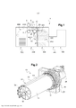
[0028] A Figura 1 ilustra muito esquematicamente um exemplo de uma máquina de estampar.[0028] Figure 1 very schematically illustrates an example of a stamping machine.
[0029] A Figura 2 mostra uma vista em perspectiva de um dispositivo para desenrolar uma tira da máquina de estampar da Figura 1 (com uma caixa transparente representada)[0029] Figure 2 shows a perspective view of a device for unrolling a strip from the printing machine of Figure 1 (with a transparent box shown)
[0030] A Figura 3 mostra outra vista do dispositivo para desenrolar uma tira da Figura 2.[0030] Figure 3 shows another view of the device for unrolling a strip of Figure 2.
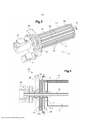
[0031] A Figura 4 mostra um corte longitudinal dos elementos do dispositivo para desenrolar uma tira da Figura 2.[0031] Figure 4 shows a longitudinal section of the elements of the device for unrolling a strip of Figure 2.
[0032] A Figura 5 mostra um corte transversal A-A dos elementos do dispositivo para desenrolar uma tira da Figura 4.[0032] Figure 5 shows an A-A cross-section of the elements of the device for unrolling a strip of Figure 4.
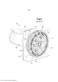
[0033] A Figura 6 mostra uma vista em perspectiva de um tambor central e uma roda dentada central do dispositivo para desenrolar uma tira da Figura 2.[0033] Figure 6 shows a perspective view of a central drum and a central sprocket of the device for unwinding a strip of Figure 2.
[0034] A Figura 7 mostra uma vista em perspectiva do anel externo e um suporte do dispositivo para desenrolar uma tira da Figura 2.[0034] Figure 7 shows a perspective view of the outer ring and a support of the device for unrolling a strip of Figure 2.
[0035] A Figura 8 mostra uma vista em perspectiva de um dispositivo condutor planetário do dispositivo para desenrolar uma tira da Figura 2.[0035] Figure 8 shows a perspective view of a planetary conductor device of the device for unwinding a strip of Figure 2.
[0036] A Figura 9 mostra outra vista do dispositivo condutor planetário da Figura 8.[0036] Figure 9 shows another view of the planetary driver device of Figure 8.
[0037] A Figura 10 mostra um corte transversal do dispositivo para desenrolar uma tira da Figura 2 enquanto desenrola uma tira a ser estampada, com o dispositivo para desenrolar a tira estando em uma primeira posição extrema.[0037] Figure 10 shows a cross-section of the device for unwinding a strip of Figure 2 while unwinding a strip to be stamped, with the device for unwinding the strip being in a first extreme position.
[0038] A Figura 11 mostra uma vista semelhante à da Figura 10 em uma segunda posição extrema.[0038] Figure 11 shows a view similar to Figure 10 in a second extreme position.
[0039] A Figura 12 mostra uma vista em perspectiva dos elementos de um dispositivo para desenrolar uma tira de acordo com uma segunda modalidade.[0039] Figure 12 shows a perspective view of the elements of a device for unwinding a strip according to a second embodiment.
[0040] Nessas Figuras, os elementos idênticos possuem os mesmos números de referência. As modalidades a seguir são exemplos. Mesmo que a descrição se refira a uma ou várias modalidades, isso não significa necessariamente que cada referência se refere à mesma modalidade, ou que as características se aplicam apenas a uma única modalidade. Características simples de diferentes modalidades também podem ser combinadas ou trocadas a fim de fornecer outras modalidades.[0040] In these Figures, identical elements have the same reference numbers. The following modalities are examples. Even if the description refers to one or more modalities, this does not necessarily mean that each reference refers to the same modality, or that the characteristics apply only to a single modality. Simple features of different modalities can also be combined or swapped to provide other modalities.
[0041] Os termos a montante e a jusante são definidos com referência à direção longitudinal de movimento das folhas (Figura 1). As folhas são colocadas de montante para jusante, geralmente seguindo o eixo longitudinal principal da máquina em um movimento, cujo ritmo é determinado por paradas periódicas.[0041] The upstream and downstream terms are defined with reference to the longitudinal direction of movement of the leaves (Figure 1). Sheets are placed from upstream to downstream, generally following the main longitudinal axis of the machine in a movement whose rhythm is determined by periodic stops.
[0042] Os termos "elementos em forma de folhas" e "folhas" serão considerados equivalentes, compreendendo também os elementos constituídos por cartão dobrado e por cartão plano, por papel ou por qualquer outro material correntemente utilizado na indústria de embalagens. É projetado que, em todo o texto, os termos "folha" ou "elemento em folhas" ou "elemento em forma de folhas" designem de forma muito geral, qualquer apoio para uma impressão em forma de folhas, tais como folhas de cartão, folhas de papel, folhas de material plástico, etc.[0042] The terms "elements in the form of sheets" and "sheets" will be considered equivalent, also comprising the elements constituted by folded cardboard and flat cardboard, paper or any other material commonly used in the packaging industry. It is intended that throughout the text the terms "sheet" or "sheet element" or "sheet element" designate very generally any support for a sheet-like print, such as sheets of cardboard, sheets of paper, sheets of plastic material, etc.
[0043] Os termos "acima", "abaixo", "baixo", "alto", "horizontal" e "vertical" são definidos em referência à colocação dos elementos em uma máquina de modelagem colocada no solo.[0043] The terms "above", "below", "low", "high", "horizontal" and "vertical" are defined in reference to the placement of elements in a modeling machine placed on the ground.
[0044] A Figura 1 representa uma modalidade de uma máquina de estampar 1 capaz de estabelecer, sobre cada folha, o filme, dourado ou metálico que é produzido por pelo menos uma tira de estampagem 2, em particular para a fabricação de embalagens.[0044] Figure 1 represents an embodiment of a
[0045] Esta máquina 1 é classicamente composta por várias estações de trabalho 100, 200, 300, 400, 500 que são justapostas, mas interdependentes entre si, para formar um conjunto unificado a fim de tratar uma sucessão de elementos em forma de folha.[0045] This
[0046] Assim, encontra-se um alimentador 100, um batente de margem 200, uma estação de estampagem 300, uma estação de alimentação de tira 400 e uma estação de recebimento 500. Um dispositivo de transferência 600 também é fornecido para mover individualmente cada folha da saída do batente de margem 200 até a estação de recebimento 500, inclusive através da estação de estampagem 300.[0046] Thus, there is a
[0047] Nesta modalidade particular, escolhida apenas como exemplo, as folhas são levantadas com sucesso do topo de uma pilha por meio de um órgão de agarramento de seção que as transporta até o batente de margem 200 diretamente adjacente.[0047] In this particular embodiment, chosen by way of example only, the sheets are successfully lifted from the top of a pile by means of a section gripping member which transports them to the directly
[0048] Ao nível do batente de margem 200, as folhas são colocadas em um tecido pelo órgão de pega de sucção, isto é, colocadas uma a seguir à outra de forma que se sobreponham parcialmente. O conjunto do tecido é então conduzido em movimento ao longo de um plano na direção da estação de estampagem 300 por meio de um mecanismo de transporte operado por correias. No final do tecido, a folha dianteira pode ser sistematicamente posicionada com precisão pelo uso de cunhas frontais e laterais ou por um sistema de nivelamento.[0048] At the level of the
[0049] A estação de trabalho situada logo após o batente de mesa 200 é, assim, a estação de estampagem 300. Esta última tem uma função de colocar sobre cada folha, por estampagem a quente, o filme metálico, que é feito por uma tira de estampagem 2. Para isso, ela usa uma prensa de placa 310 dentro da qual a operação de estampagem é executada de uma maneira clássica, entre uma placa de aquecimento superior 320 que é fixa, e uma placa inferior 330 que é montada para se mover seguindo um movimento vertical para frente e para trás.[0049] The workstation located just after the
[0050] A estação de alimentação para a tira 400 é carregada para garantir alimentação simultânea da máquina 1 na tira de estampagem 2, e a evacuação desta mesma tira 2 que foi usada, uma vez após ser passada para a estação de estampagem 300.[0050] The feeding station for the
[0051] O processo de tratamento das folhas na máquina de estampagem 1 é concluído na estação de recebimento 500, cuja função principal é a de reembalar as folhas que já foram tratadas em uma pilha. Para tal, o dispositivo de transporte 600 é, por exemplo, construído de forma a liberar automaticamente cada folha quando esta se encontra à direita desta nova pilha. Caso contrário, a folha cairia em ângulos retos no topo da pilha.[0051] The process of treating the sheets in the stamping
[0052] De uma maneira muito clássica, o conjunto de dispositivo de transporte 600 estabelece uma série de barras de pinça que é montada para ser móvel usando duas séries de correntes 620 colocadas lateralmente em cada lado da máquina de estampagem 1. Cada série de correntes 620 corre através de um circuito que permite que as barras de pinça sigam uma trajetória que passa sucessivamente através da estação de estampagem 300, da estação de alimentação de tiras 400 e da estação de recebimento 500.[0052] In a very classical manner, the
[0053] O conjunto das barras de pinça sairá de uma posição parada, acelerará, atingirá a velocidade máxima, desacelerará e depois parará, enquanto descreve um ciclo correspondente ao movimento de uma folha, desde uma estação de trabalho até a estação seguinte. As séries de correntes 620 se movem e param periodicamente de forma que, durante cada parada, todas as barras de pinça segurando uma folha são passadas de uma estação para a estação de trabalho adjacente a jusante. Cada estação faz seu trabalho sincronizado com este ciclo, que é chamado no total de um ciclo de máquina. As estações de trabalho iniciam um novo trabalho no início de cada ciclo de máquina.[0053] The set of gripper bars will leave a stopped position, accelerate, reach maximum speed, decelerate and then stop, while describing a cycle corresponding to the movement of a sheet, from one workstation to the next station. The series of
[0054] A estação de alimentação para a tira 400 compreende pelo menos um dispositivo para desenrolar uma tira 10, que pode ser acumulada a partir da tira de estampagem 2 em uma forma pré- desenrolada a jusante de pelo menos um carretel de estampagem 3 e pode entregar a tira pré-desenrolada sobre cada solicitação de um eixo de avanço da máquina 1.[0054] The feeding station for the
[0055] Para isso, o dispositivo para desenrolar uma tira 10 é interposto entre, pelo menos, um carretel de estampagem 3 e a prensa de placa 310 (Figura 1).[0055] For this, the device for unwinding a
[0056] Além disso, como se pode ver melhor, em particular nas Figuras 2 a 11, o dispositivo para desenrolar uma tira 10 compreende um tambor central 11, um rolo satélite 14 e um dispositivo planetário condutor 15.[0056] Furthermore, as can be seen better, particularly in Figures 2 to 11, the device for unwinding a
[0057] O tambor central 11 está configurado para ser conduzido em uma rotação com velocidade de avanço variável, unificado em sua rotação com um eixo 16 do dispositivo para desenrolar uma tira 10. A cada ciclo de máquina, a velocidade de avanço pilotada pela máquina 1 aumenta e então diminui (fala-se de "avanço") e então para. Esta etapa de avanço (avançar e depois parar) é feita para que a tira a ser estampada 2 coincida com uma folha para colocação por estampagem do filme metálico de acordo com um programa pré- definido na máquina 1. Os avanços podem ser idênticos ou diferentes entre cada parada, ou diferente entre pelo menos duas paradas sucessivas e periódicas.[0057] The
[0058] O rolo satélite 14 apresenta um eixo 21 construído paralelo ao eixo 16 do tambor central 11. O rolo satélite 14 pode girar em torno do tambor central 11.[0058]
[0059] Durante o funcionamento, a tira pré-desenrolada pode ser feita rolar em torno do tambor central 11 (por pelo menos uma rotação) pelo efeito do movimento do rolo satélite 14. Mais precisamente, a tira pré-desenrolada rola em torno do tambor central 11 depois de passar pelo rolo satélite 14, formando uma alavanca da tira pré-desenrolada (Figuras 10 e 11).[0059] During operation, the pre-unrolled strip can be rolled around the central drum 11 (for at least one rotation) by the effect of the movement of the
[0060] De acordo com uma modalidade, o dispositivo conductor planetário 15 compreende uma roda dentada central 12, um anel externo 13, uma porta satélite 17, e pelo menos uma roda dentada satélite 20 (Figuras 4 e 5).[0060] According to one embodiment, the
[0061] A roda dentada central 12 é unificada em sua rotação com o tambor central 11, e é coaxial ao tambor central 11 (Figura 6). Por exemplo, eles são fixados ao eixo 16 (Figura 4). Por exemplo, um mancal suporta a extremidade oposta do eixo 16.[0061] The
[0062] Por exemplo, o raio original da roda dentada central 12 cor responde ao raio externo do tambor central 11 (Figura 6).[0062] For example, the original radius of the
[0063] O anel externo 13 é denteado (Figura 7). É coaxial à roda dentada central 12 e está configurado para ser colocado em rotação a uma velocidade constante. "Constante" significa uma velocidade aproximadamente constante, ou seja, por exemplo, variando menos de +/- 10% de uma velocidade média. A velocidade constante é, por exemplo, apro-ximadamente igual a um valor médio da velocidade de avanço variável.[0063] The
[0064] A direção de rotação do anel externo 13 é oposta à direção de rotação do tambor central 11. A direção de rotação do anel externo 13 é escolhida de modo que a rotação do anel externo 13 desenrole o carretel de estampagem 3.[0064] The direction of rotation of the
[0065] Por exemplo, o anel externo 13 é suportado por um suporte 19 montado em rotação sobre o eixo 16 por meio de um mancal (Figura 4). Na direção axial, a roda dentada central 12 é interposta entre o tambor central 11 e o suporte 19 do anel externo 13.[0065] For example, the
[0066] O rolo satélite 14, por exemplo, apresenta um diâmetro menor em tamanho do que o espaço radial localizado entre o diâmetro original do anel externo 13 e o diâmetro externo do tambor central 11, o que permite que um fio interno da tira a ser estampada 2 seja enrolado sobre o tambor central 11 a ser interposto sem ser preso entre o rolo satélite 14 e o tambor central 11.[0066]
[0067] A porta satélite 17 está unida em movimento ao rolo satellite 14 em torno do tambor central 11 e coaxial ao tambor central 11. A porta satélite 17 é, por exemplo, montada em rotação no eixo 16 por meio de um mancal (Figura 4).[0067]
[0068] Como um exemplo, a porta satélite 17 é formada por um lado por um disco 17a, por exemplo sólido, que apresenta um mancal no centro, e por outro lado por um anel 17b fixado coaxialmente ao disco 17a e suportando mancais planos para os eixos da pelo menos uma roda dentada satélite 20, e conforme aplicável e como se verá mais tarde, das rodas dentadas 18 e 24 (Figuras 4, 8 e 9).[0068] As an example, the
[0069] A pelo menos uma roda dentada satélite 20 está montada sobre a porta satélite 17. Ela engata por um lado o anel externo 13 e, por outro lado, a roda dentada central 12, para ser colocada em rotação em uma direção ou outra do tambor central 11 como uma função da diferença de velocidades de rotação do tambor central 11 e do anel externo 13. O movimento da pelo menos uma roda dentada satélite 20 conduz o movimento do mancal satélite 14 em torno do tambor central 11, o que causa variação no comprimento da tira pré-desenrolada.[0069] The at least one
[0070] O dispositivo condutor planetário 15 compreende, por exemplo, quatro rodas dentadas satélites 20 montadas sobre a porta satélite 17, por exemplo, descritas em forma de uma cruz (Figuras 5, 8 e 9).[0070] The
[0071] As rodas dentadas satélites 20 transmitem a condução do anel externo 13 e da roda dentada central 12 para a porta satélite 17, unidas em seu movimento ao mancal satélite 14. As rodas dentadas satélites 20 não estão elas mesmas conectadas a qualquer mancal satélite.[0071]
[0072] O diâmetro da pelo menos uma roda dentada satélite 20 é, por exemplo, aproximadamente maior do que o diâmetro do mancal satélite 14.[0072] The diameter of the at least one
[0073] As rodas dentadas satélites 20, a roda dentada central 12 e o anel externo 13 são construídos em uma extremidade do eixo 16, aproximadamente sobre o mesmo plano. Elas são, por exemplo, recebidas em uma caixa 28 (Figuras 2 e 3). Esta construção dos itens engatados também é chamada de "trem epiciclóide" ou "guia planetária", com o "interior planetário" ou "sol" sendo a roda dentada central 12, e o "exterior planetário" ou "anel" sendo o anel externo 13 e o "satélite" que engata os dois planetários e girando em torno do seu eixo comum que é a roda dentada satélite 20, o "eixo comum" sendo o eixo 16.[0073]
[0074] De acordo com uma modalidade, o mancal satélite 14 é rotativo e pode girar sobre si mesmo em torno do seu eixo 21. A tira de estampagem 2 pode, assim, rolar sem esfregar em torno do mancal satélite 14.[0074] According to one embodiment, the
[0075] De acordo com uma modalidade, o dispositivo conductor planetário 15 consiste, em adição, de uma roda dentada 18 montada sobre a porta satélite 17, unida em movimento ao rolo satélite 14 e engatando o anel externo 13. A roda dentada 18 e o mancal satélite 14 são, por exemplo, montados sobre o eixo 21 em uma extremidade do mancal satélite 14 (Figura 4). Uma área de mancal plana suporta, por exemplo, a extremidade oposta do eixo 21 do mancal satélite 14. O raio original da roda dentada 18 corresponde, por exemplo, ao raio externo do mancal satélite 14. A velocidade de rotação circunferencial do mancal satélite 14, portanto, corresponde à velocidade de rotação do anel externo 13 ao qual a tira a ser estampada 2 é desenrolada do carretel de estampagem 3. A tira a ser estampada 2 pode, assim, ser conduzida pelo mancal satélite 14 na mesma velocidade que o desen- rolamento da bobina de estampagem 3.[0075] According to one embodiment, the
[0076] De acordo com outra modalidade, o rolo satélite 14 não é rotativo. Ele é, por exemplo, fixado à porta satélite 17. Neste caso, o rolo satélite 14 pode ser poroso, e apresentar uma cavidade interna configurada para ser colocada em comunicação com o ar pressurizado, de uma maneira a formar uma almofada de ar sob a tira a ser estampada 2, de modo que a tira a ser estampada 2 possa rolar ao redor do rolo satélite 14 sem esfregar.[0076] According to another embodiment, the
[0077] De acordo com uma modalidade, o dispositivo condutor planetário 15 compreende, além disso, uma guia 22 unida em movimento ao rolo satélite 14 em torno do tambor central 11 (Figuras 8 e 9).[0077] According to one embodiment, the
[0078] A guia 22 pode ser interposta entre dois fios da tira pré-desenrolada 2, com um fio interior da tira a ser estampada 2 estando contra o tambor central 11, e um fio exterior para guiar um fio exterior da tira (Figuras 10 e 11).[0078] The
[0079] De acordo com uma modalidade, a guia 22 compreende entre um e dez, tais como cinco, rolos satélites adicionais 23, com o rolo ou rolos satélites adicionais 23 e o rolo satélite 14 descrevendo um círculo C (Figura 9). Os rolos satélites adicionais 23 e o rolo satélite 14 são, por exemplo, regularmente espaçados, por exemplo, sobre um arco de um círculo inclusive entre 90° e 180°. A guia 22 também pode compreender um elemento de manutenção 34 para manter e guiar as extremidades opostas dos rolos satélites adicionais 23 em torno do eixo 16.[0079] According to one embodiment, the
[0080] O rolo satélite adicional ou rolos 23, podem ser rotativos. O fio exterior da tira pré-desenrolada pode, assim, deslizar sobre os rolos satélites rotativos adicionais 23 praticamente sem esfregar.[0080] The additional satellite roller or
[0081] No exemplo das Figuras 1 a 11, a guia 22 compreende entre um e dez, tais como cinco, rolos satélites rotativos adicionais 23 e quantas rodas dentadas 24 montadas sobre a porta satélite 17 (Figuras 5 e 8). As rodas dentadas 24 são unidas em sua rotação com seu respectivo rolo satélite adicional 23. Elas são montadas em uma extremidade axial de um rolo satélite adicional 23, respectivamente, e engatam no anel externo 13. Uma área de mancal plano pode suportar a extremidade oposta de cada rolo satélite adicional 23.[0081] In the example of Figures 1 to 11, the
[0082] Os rolos satélites adicionais 23 e as rodas dentadas 24 apresentam, por exemplo, diâmetros com dimensões semelhantes às do rolo satélite 14. O fio interior da tira a ser estampada 2 também pode ser interposto sem se prender entre, por um lado, o rolo satélite 14 e os rolos satélites adicionais 23 e, por outro lado, o tambor central 11.[0082] The additional satellite rolls 23 and the
[0083] O diâmetro do referido círculo C do anel externo 13 corresponde aproximadamente ao diâmetro original do anel externo 13. A velocidade de rotação circunferencial dos rolos satélites adicionais 23 corresponde à velocidade de rotação do anel externo 13, para o qual a tira a ser estampada 2 é desenrolada do carretel de estampagem 3. A tira a ser estampada 2 pode, assim, ser conduzida pelos rolos satélites adicionais 23 na mesma velocidade em que é desenrolada do carretel de estampagem 3.[0083] The diameter of said circle C of the
[0084] A tira a ser estampada 2 proveniente do carretel de estampagem 3 pode, assim, ser guiada pelos rolos satélites adicionais 23 de uma maneira que o fio externo segue aproximadamente o diâmetro original do anel externo 13, com o fio externo sendo aproximadamente paralelo ao fio interno da tira que rola em torno do tambor central 11. Além disso, existem rolos satélites adicionais 23, e a orientação do fio externo é próxima a um círculo, algo que permite evitar sobressaltos no desenrolar da tira.[0084] The strip to be embossed 2 from the
[0085] A guia 22 também pode compreender uma placa 32, ou elementos de uma placa, fixada à porta satélite 17 em um arco de um círculo, a fim de guiar o fio interno da tira a ser estampada 2 contra o tambor central 11 (Figuras 8 a 11).[0085] The
[0086] Entre o carretel de estampagem 3 e o dispositivo para desenrolar uma tira 10, a tira a ser estampada 2 é, por exemplo, orientada tangencial aos rolos satélites adicionais 23 pela alavanca de introdução 26. Ao deixar o dispositivo para desenrolar uma tira 10, a tira a ser estampada 2 pode ser alavancada para a posição horizontal por meio de uma alavanca de saída 27 a fim de guiar a tira 2 para um plano na prensa de placa 310 (Figura 1).[0086] Between the
[0087] De acordo com uma modalidade, está planejado que o dispositivo para desenrolar uma tira 10 compreende um motor 25 configurado para conduzir o eixo 16 do tambor central 11 a uma velocidade de avanço variável (Figuras 3 e 4). O motor 25 está, por exemplo, em uma conexão direta com a extremidade do eixo 16. O eixo 16, unido em rotação ao tambor central 11 para desenrolar a tira a ser estampada 2, forma assim também o eixo de avanço. O número de peças pode assim ser reduzido.[0087] According to one embodiment, it is planned that the device for unwinding a
[0088] O dispositivo para desenrolar uma tira 10 pode também compreender um rolo para avançar 29, que pressiona contra o tambor central 11 para garantir uma boa transmissão entre a tira a ser estampada 2 e o tambor central 11 (Figura 1).[0088] The device for unwinding a
[0089] O anel externo 13 pode ser conduzido em rotação a uma velocidade constante por um motor suplementar 31 do dispositivo para desenrolar uma tira 10 (Figura 3). O motor suplementar 31 conduz o anel externo 13, por exemplo, por meio de um sistema de polias.[0089] The
[0090] Em funcionamento, o anel externo 13 é conduzido em rotação a uma velocidade constante, por exemplo, a uma velocidade de rotação aproximadamente igual ao valor médio da velocidade de avanço variável (no sentido anti-horário no exemplo das Figuras 10 e 11).[0090] In operation, the
[0091] Quando a velocidade de avanço é zero (Figura 10), o rolo satélite 14 é conduzido (aqui no sentido de rotação anti-horário) em torno do tambor central 11 pelo anel externo 13. O movimento do rolo satélite 14 tem o efeito de aumentar o comprimento da tira pré- desenrolada e, portanto, a quantidade de reserva de tira que é acumulada. A Figura 10 ilustra assim uma primeira posição extrema do rolo satélite 14, para a qual a reserva da tira pré-desenrolada está em um máximo. Enquanto o rolo satélite 14 se move em torno do tambor central 11 para alcançar sua primeira posição extrema, o posicionamento do filme dourado ou metálico é realizado sobre uma folha na prensa de placa 310.[0091] When the feed speed is zero (Figure 10), the
[0092] Então, quando a velocidade de avanço aumenta (Figura 11), o tambor central 11 é levado à rotação na direção contrária à do anel externo 13 (no sentido horário na Figura 11) conduzindo a rotação do rolo satélite 14 na mesma direção, o que reduz o comprimento da tira pré-desenrolada que é entregue à estação de estampagem 400. A Figura 11 mostra um exemplo de uma segunda posição extrema do rolo satélite 14, para a qual a reserva da tira pré-desenrolada está em um mínimo.[0092] Then, when the feed speed increases (Figure 11), the
[0093] Então, a velocidade de avanço diminui até parar. Conse-quentemente, o rolo satélite 14 é conduzido (aqui no sentido anti- horário) em torno do tambor central 11 pelo anel externo 13 até o ponto onde ele volta à sua primeira posição extrema (Figura 10). Um novo ciclo de máquina é iniciado e prossegue.[0093] Then the feedrate slows to a stop. Consequently, the
[0094] A tira a ser estampada 2 pode, então, ser pré-desenrolado à velocidade constante do carretel de estampagem 3, trazida pelo rolo satélite 14. A tira pode ser entregue ao sair do dispositivo para desenrolar uma tira 10 na velocidade de avanço variável dada pelo tambor central 11. O comprimento acumulado do texto a ser estampado 2 varia de acordo com o movimento angular do rolo satélite 14 em torno do tambor central 11, o qual varia em torno dele, devido à condução planetária, como uma função da diferença das velocidades de rotação do tambor central 11 e do anel externo 13. É assim possível acumular a tira a ser estampada 2 e, em seguida, entregar a tira acumulada a ser estampada 2 a cada solicitação do eixo condutor.[0094] The strip to be embossed 2 can then be pre-unrolled at the constant speed of the
[0095] Vários carretéis 3 também podem ser desenrolados com o dispositivo para desenrolar uma tira 10, se estas forem entregues na estação de estampagem 300 com a mesma velocidade de avanço.[0095]
[0096] Entende-se que o dispositivo para desenrolar uma tira 10 é mais compacto do que um sistema "linear" do estado da arte anterior, porque ele pode ser integrado diretamente na máquina 1. É também mais robusto e mais fácil de configurar em movimento. A distância entre o carretel 3 e a prensa 310 pode ser pequena, o que permite um aumento na precisão da colocação da tira e, assim, permite uma redução na quantidade de tira consumida. O desenrolamento do carretel de estampagem 3 pode continuar a ser travado durante a produção por meio de um dispositivo de frenagem, a fim de garantir tensão mínima da tira de uma forma muito mais suave, algo que permite evitar sobressaltos que podem fazer com que a tira se deteriore.[0096] It is understood that the device for unwinding a
[0097] A Figura 12 ilustra outra modalidade do dispositivo para de- senrolar uma tira 10'.[0097] Figure 12 illustrates another embodiment of the device for unrolling a strip 10'.
[0098] Este exemplo difere do anterior pelo fato de aqui a guia 33 compreender um elemento metálico, tal como uma folha metálica ou uma peça de chapa metálica, que apresenta entre uma e dez, por exemplo cinco, dobras ou curvas 30.[0098] This example differs from the previous one in that the
[0099] Uma extremidade axial do elemento metálico é fixada à por ta satélite 17. A guia 33 também pode compreender um elemento de manutenção 34 para manter e guiar a extremidade oposta do elemento metálico em torno do eixo 16.[0099] An axial end of the metallic element is fixed to the
[00100] As dobras ou curvas 30 e o rolo satélite 14 (na direção radial como o eixo 16) descrevem um círculo, coaxial com o anel externo 13. O diâmetro do referido círculo corresponde, por exemplo, aproximadamente, ao diâmetro original do anel externo 13.[00100] The folds or bends 30 and the satellite roller 14 (in the radial direction as the axis 16) describe a circle, coaxial with the
[00101] As dobras ou curvas 30 são, por exemplo, regularmente espaçadas, por exemplo, sobre um círculo de um arco compreendido entre 90° e 180°.[00101] The folds or curves 30 are, for example, regularly spaced, for example on a circle of an arc comprised between 90° and 180°.
[00102] O fio externo da tira pré-desenrolada também pode deslizar sobre as dobras ou curvas 30 praticamente sem esfregar. A tira a ser estampada 2 proveniente do carretel de estampagem 3 pode, assim, ser guiada pelas dobras e curvas 30 em uma forma que o fio externo segue aproximadamente o diâmetro original do anel externo 13, com o fio externo sendo aproximadamente paralelo ao fio interno da tira que rola em torno do tambor central 11. Quanto mais dobras ou curvas 30, mais orientação do fio externo está próxima de um círculo, algo que permite evitar sobressaltos ao desenrolar a tira.[00102] The outer wire of the pre-unrolled strip can also slide over the folds or bends 30 with virtually no rubbing. The strip to be embossed 2 from the
Claims (17)
Applications Claiming Priority (3)
| Application Number | Priority Date | Filing Date | Title |
|---|---|---|---|
| EP18020442 | 2018-09-10 | ||
| EP18020442.2 | 2018-09-10 | ||
| PCT/EP2019/025298 WO2020052809A1 (en) | 2018-09-10 | 2019-09-06 | Device for unwinding strips and machine for stamping elements in sheet form |
Publications (2)
| Publication Number | Publication Date |
|---|---|
| BR112021001649A2 BR112021001649A2 (en) | 2021-05-04 |
| BR112021001649B1 true BR112021001649B1 (en) | 2022-07-26 |
Family
ID=63557198
Family Applications (1)
| Application Number | Title | Priority Date | Filing Date |
|---|---|---|---|
| BR112021001649-0A BR112021001649B1 (en) | 2018-09-10 | 2019-09-06 | DEVICE TO UNROOL A STRIP AND MACHINE TO STAMP ELEMENTS IN THE SHAPE OF SHEET |
Country Status (10)
| Country | Link |
|---|---|
| US (1) | US11180335B2 (en) |
| EP (1) | EP3810537B1 (en) |
| JP (1) | JP7119219B2 (en) |
| KR (1) | KR102320620B1 (en) |
| CN (1) | CN112654571B (en) |
| BR (1) | BR112021001649B1 (en) |
| ES (1) | ES2955716T3 (en) |
| RU (1) | RU2758611C1 (en) |
| TW (1) | TWI719628B (en) |
| WO (1) | WO2020052809A1 (en) |
Families Citing this family (2)
| Publication number | Priority date | Publication date | Assignee | Title |
|---|---|---|---|---|
| TWI804078B (en) * | 2020-12-17 | 2023-06-01 | 瑞士商巴柏斯特麥克斯合資公司 | Sheet processing machine |
| CN115724262A (en) * | 2021-08-31 | 2023-03-03 | 宁德时代新能源科技股份有限公司 | Roller assembly, manufacturing equipment of battery monomer and adjusting method of roller |
Family Cites Families (10)
| Publication number | Priority date | Publication date | Assignee | Title |
|---|---|---|---|---|
| CH292425A (en) * | 1950-01-10 | 1953-08-15 | Etudes De Machines Speciales | Device intended to be interposed between a member for feeding a strip or a flexible wire and a member for using this strip. |
| SU376247A1 (en) * | 1969-07-03 | 1973-04-05 | Проектно конструкторское бюро проектированию оборудовани производства пластических масс , синтетических смол | METHOD OF TRANSPORTATION OF BELT MATERIAL |
| CH690547A5 (en) * | 1995-05-08 | 2000-10-13 | Bobst Sa | Feed device of a band in the working station stopped, this band arriving continuously. |
| JPH09309645A (en) * | 1996-05-21 | 1997-12-02 | Citizen Watch Co Ltd | Sheet releasing device of automatic sheet feeder |
| RU2170209C1 (en) * | 2000-05-31 | 2001-07-10 | Зао "Стабо+" | Method of and device for making packages from thin tape material |
| PL1991376T3 (en) * | 2006-03-09 | 2012-04-30 | Sekisui Rib Loc Australia Pty Ltd | Method and apparatus for stabilising strip during winding |
| KR101242777B1 (en) | 2008-12-04 | 2013-03-12 | 봅스트 맥스 에스에이 | Device for supplying power to a conversion unit with a continuous strip substrate for a power supply station in a packaging production machine |
| US20130327235A1 (en) | 2011-02-28 | 2013-12-12 | Bobst Mex Sa | Foil unwinding device for stamping machine |
| CN105492354B (en) * | 2013-07-01 | 2017-11-17 | 鲍勃斯脱梅克斯股份有限公司 | The brake apparatus of band reel |
| CN108340663B (en) * | 2017-01-23 | 2020-02-07 | 长胜纺织科技发展(上海)有限公司 | Paperless transfer printing machine |
-
2019
- 2019-09-06 ES ES19769382T patent/ES2955716T3/en active Active
- 2019-09-06 KR KR1020217006562A patent/KR102320620B1/en active IP Right Grant
- 2019-09-06 WO PCT/EP2019/025298 patent/WO2020052809A1/en unknown
- 2019-09-06 BR BR112021001649-0A patent/BR112021001649B1/en active IP Right Grant
- 2019-09-06 US US17/274,344 patent/US11180335B2/en active Active
- 2019-09-06 JP JP2021512936A patent/JP7119219B2/en active Active
- 2019-09-06 EP EP19769382.3A patent/EP3810537B1/en active Active
- 2019-09-06 CN CN201980058931.8A patent/CN112654571B/en active Active
- 2019-09-06 RU RU2021109658A patent/RU2758611C1/en active
- 2019-09-09 TW TW108132447A patent/TWI719628B/en active
Also Published As
| Publication number | Publication date |
|---|---|
| KR20210032533A (en) | 2021-03-24 |
| US11180335B2 (en) | 2021-11-23 |
| BR112021001649A2 (en) | 2021-05-04 |
| ES2955716T3 (en) | 2023-12-05 |
| TW202017834A (en) | 2020-05-16 |
| CN112654571B (en) | 2022-03-08 |
| EP3810537B1 (en) | 2023-08-09 |
| JP2021527609A (en) | 2021-10-14 |
| CN112654571A (en) | 2021-04-13 |
| KR102320620B1 (en) | 2021-11-02 |
| RU2758611C1 (en) | 2021-11-01 |
| US20210245985A1 (en) | 2021-08-12 |
| JP7119219B2 (en) | 2022-08-16 |
| WO2020052809A1 (en) | 2020-03-19 |
| TWI719628B (en) | 2021-02-21 |
| EP3810537A1 (en) | 2021-04-28 |
Similar Documents
| Publication | Publication Date | Title |
|---|---|---|
| ES2663908T3 (en) | Rewinding machine and procedure for the production of rolls of web material | |
| ES2675312T3 (en) | Rewind machine and procedure | |
| ITFI960040A1 (en) | REWINDING MACHINE INCORPORATING A GLUER FOR THE COMPLETED ROLLS AND RELATIVE WINDING METHOD | |
| BR112021001649B1 (en) | DEVICE TO UNROOL A STRIP AND MACHINE TO STAMP ELEMENTS IN THE SHAPE OF SHEET | |
| JP2009512601A (en) | Method and apparatus for packaging a group of products arranged in one or more layers | |
| ITFI20060014A1 (en) | REWINDING MACHINE AND WINDING METHOD FOR THE PRODUCTION OF ROLLS | |
| US789707A (en) | Method of forming rolls of sheets of paper or other flexible material. | |
| JP5134731B2 (en) | Paper sheet storage and feeding device | |
| ITFI20100245A1 (en) | "REWINDING MACHINE AND WINDING METHOD" | |
| CN107364751A (en) | The machine and method of winding band with transverse cuts and anchor | |
| JPH0217459B2 (en) | ||
| BR112014024763B1 (en) | "DRIVING DEVICE FOR PRINTING STRIP, STRAINER MODULE AND STANDARD STAMPING MACHINE | |
| JP4445455B2 (en) | Tape drawing device for labeling machine and labeling machine | |
| US1837241A (en) | Sheet feeding mechanism | |
| CN110857157A (en) | Label loading attachment | |
| BR112014000967B1 (en) | method of breaking a moving coil, and, coil cutting system | |
| ITRM960465A1 (en) | WRAPPING MACHINE AND RELATED METHOD | |
| US603602A (en) | crowell | |
| IT201900012657A1 (en) | PACKAGING SYSTEM | |
| IT202100009248A1 (en) | EQUIPMENT FOR CUTTING AND CONVEYING A BELT OF MATERIAL AND RELATED METHOD FOR THE PRODUCTION OF ELECTRIC ENERGY STORAGE DEVICES | |
| ITRM970383A1 (en) | WRAPPING MACHINE AND RELATED METHOD | |
| JPH0818737B2 (en) | Web winding machine and method | |
| BR112014005574B1 (en) | method and system for forming spiral rolls | |
| ITTO960340A1 (en) | METHOD FOR PACKING SOCKS. | |
| JP2016062229A (en) | Tape take-up type bill reflux device and reflux type bill processing device |
Legal Events
| Date | Code | Title | Description |
|---|---|---|---|
| B06A | Patent application procedure suspended [chapter 6.1 patent gazette] | ||
| B09A | Decision: intention to grant [chapter 9.1 patent gazette] | ||
| B16A | Patent or certificate of addition of invention granted [chapter 16.1 patent gazette] |
Free format text: PRAZO DE VALIDADE: 20 (VINTE) ANOS CONTADOS A PARTIR DE 06/09/2019, OBSERVADAS AS CONDICOES LEGAIS |