BR112016027296B1 - Filter for a suction system - Google Patents
Filter for a suction system Download PDFInfo
- Publication number
- BR112016027296B1 BR112016027296B1 BR112016027296-0A BR112016027296A BR112016027296B1 BR 112016027296 B1 BR112016027296 B1 BR 112016027296B1 BR 112016027296 A BR112016027296 A BR 112016027296A BR 112016027296 B1 BR112016027296 B1 BR 112016027296B1
- Authority
- BR
- Brazil
- Prior art keywords
- filter
- raised areas
- wall
- microns
- areas
- Prior art date
Links
- 238000001914 filtration Methods 0.000 claims abstract description 33
- 239000012530 fluid Substances 0.000 claims abstract description 19
- 239000004033 plastic Substances 0.000 claims abstract description 16
- HEFNNWSXXWATRW-UHFFFAOYSA-N Ibuprofen Chemical compound CC(C)CC1=CC=C(C(C)C(O)=O)C=C1 HEFNNWSXXWATRW-UHFFFAOYSA-N 0.000 claims description 4
- 230000015572 biosynthetic process Effects 0.000 abstract description 12
- 238000002347 injection Methods 0.000 abstract description 7
- 239000007924 injection Substances 0.000 abstract description 7
- 210000000988 bone and bone Anatomy 0.000 abstract description 4
- 238000004049 embossing Methods 0.000 abstract description 2
- 238000012423 maintenance Methods 0.000 abstract 1
- XLYOFNOQVPJJNP-UHFFFAOYSA-N water Substances O XLYOFNOQVPJJNP-UHFFFAOYSA-N 0.000 abstract 1
- 239000010410 layer Substances 0.000 description 25
- 239000000446 fuel Substances 0.000 description 19
- 238000000034 method Methods 0.000 description 13
- 238000005755 formation reaction Methods 0.000 description 11
- 238000005530 etching Methods 0.000 description 8
- 239000007788 liquid Substances 0.000 description 7
- 238000000926 separation method Methods 0.000 description 7
- 239000000463 material Substances 0.000 description 6
- 238000000465 moulding Methods 0.000 description 5
- 239000002828 fuel tank Substances 0.000 description 4
- 239000011241 protective layer Substances 0.000 description 4
- 238000003856 thermoforming Methods 0.000 description 4
- 238000011109 contamination Methods 0.000 description 3
- 238000003780 insertion Methods 0.000 description 3
- 230000037431 insertion Effects 0.000 description 3
- 210000001520 comb Anatomy 0.000 description 2
- 238000010276 construction Methods 0.000 description 2
- 238000004519 manufacturing process Methods 0.000 description 2
- 241000782128 Albizia adianthifolia Species 0.000 description 1
- 239000004677 Nylon Substances 0.000 description 1
- XSQUKJJJFZCRTK-UHFFFAOYSA-N Urea Chemical compound NC(N)=O XSQUKJJJFZCRTK-UHFFFAOYSA-N 0.000 description 1
- DHKHKXVYLBGOIT-UHFFFAOYSA-N acetaldehyde Diethyl Acetal Natural products CCOC(C)OCC DHKHKXVYLBGOIT-UHFFFAOYSA-N 0.000 description 1
- 125000002777 acetyl group Chemical class [H]C([H])([H])C(*)=O 0.000 description 1
- 230000000903 blocking effect Effects 0.000 description 1
- -1 but not limited to Substances 0.000 description 1
- 239000004202 carbamide Substances 0.000 description 1
- 230000006835 compression Effects 0.000 description 1
- 238000007906 compression Methods 0.000 description 1
- 230000006866 deterioration Effects 0.000 description 1
- 239000002283 diesel fuel Substances 0.000 description 1
- 239000000428 dust Substances 0.000 description 1
- 230000000694 effects Effects 0.000 description 1
- 239000003000 extruded plastic Substances 0.000 description 1
- 239000004744 fabric Substances 0.000 description 1
- 238000001746 injection moulding Methods 0.000 description 1
- 238000009434 installation Methods 0.000 description 1
- 239000010687 lubricating oil Substances 0.000 description 1
- 239000011159 matrix material Substances 0.000 description 1
- 239000002184 metal Substances 0.000 description 1
- 229920001778 nylon Polymers 0.000 description 1
- 239000002245 particle Substances 0.000 description 1
- 239000002985 plastic film Substances 0.000 description 1
- 229920000728 polyester Polymers 0.000 description 1
- 238000005096 rolling process Methods 0.000 description 1
- 230000003068 static effect Effects 0.000 description 1
Images


Classifications
-
- B—PERFORMING OPERATIONS; TRANSPORTING
- B01—PHYSICAL OR CHEMICAL PROCESSES OR APPARATUS IN GENERAL
- B01D—SEPARATION
- B01D29/00—Filters with filtering elements stationary during filtration, e.g. pressure or suction filters, not covered by groups B01D24/00 - B01D27/00; Filtering elements therefor
- B01D29/11—Filters with filtering elements stationary during filtration, e.g. pressure or suction filters, not covered by groups B01D24/00 - B01D27/00; Filtering elements therefor with bag, cage, hose, tube, sleeve or like filtering elements
- B01D29/111—Making filtering elements
-
- B—PERFORMING OPERATIONS; TRANSPORTING
- B01—PHYSICAL OR CHEMICAL PROCESSES OR APPARATUS IN GENERAL
- B01D—SEPARATION
- B01D29/00—Filters with filtering elements stationary during filtration, e.g. pressure or suction filters, not covered by groups B01D24/00 - B01D27/00; Filtering elements therefor
- B01D29/11—Filters with filtering elements stationary during filtration, e.g. pressure or suction filters, not covered by groups B01D24/00 - B01D27/00; Filtering elements therefor with bag, cage, hose, tube, sleeve or like filtering elements
- B01D29/114—Filters with filtering elements stationary during filtration, e.g. pressure or suction filters, not covered by groups B01D24/00 - B01D27/00; Filtering elements therefor with bag, cage, hose, tube, sleeve or like filtering elements arranged for inward flow filtration
-
- B—PERFORMING OPERATIONS; TRANSPORTING
- B01—PHYSICAL OR CHEMICAL PROCESSES OR APPARATUS IN GENERAL
- B01D—SEPARATION
- B01D35/00—Filtering devices having features not specifically covered by groups B01D24/00 - B01D33/00, or for applications not specifically covered by groups B01D24/00 - B01D33/00; Auxiliary devices for filtration; Filter housing constructions
- B01D35/02—Filters adapted for location in special places, e.g. pipe-lines, pumps, stop-cocks
- B01D35/027—Filters adapted for location in special places, e.g. pipe-lines, pumps, stop-cocks rigidly mounted in or on tanks or reservoirs
- B01D35/0273—Filtering elements with a horizontal or inclined rotation or symmetry axis submerged in tanks or reservoirs
-
- B—PERFORMING OPERATIONS; TRANSPORTING
- B01—PHYSICAL OR CHEMICAL PROCESSES OR APPARATUS IN GENERAL
- B01D—SEPARATION
- B01D39/00—Filtering material for liquid or gaseous fluids
- B01D39/08—Filter cloth, i.e. woven, knitted or interlaced material
- B01D39/083—Filter cloth, i.e. woven, knitted or interlaced material of organic material
-
- B—PERFORMING OPERATIONS; TRANSPORTING
- B29—WORKING OF PLASTICS; WORKING OF SUBSTANCES IN A PLASTIC STATE IN GENERAL
- B29C—SHAPING OR JOINING OF PLASTICS; SHAPING OF MATERIAL IN A PLASTIC STATE, NOT OTHERWISE PROVIDED FOR; AFTER-TREATMENT OF THE SHAPED PRODUCTS, e.g. REPAIRING
- B29C51/00—Shaping by thermoforming, i.e. shaping sheets or sheet like preforms after heating, e.g. shaping sheets in matched moulds or by deep-drawing; Apparatus therefor
- B29C51/08—Deep drawing or matched-mould forming, i.e. using mechanical means only
- B29C51/082—Deep drawing or matched-mould forming, i.e. using mechanical means only by shaping between complementary mould parts
-
- B—PERFORMING OPERATIONS; TRANSPORTING
- B29—WORKING OF PLASTICS; WORKING OF SUBSTANCES IN A PLASTIC STATE IN GENERAL
- B29C—SHAPING OR JOINING OF PLASTICS; SHAPING OF MATERIAL IN A PLASTIC STATE, NOT OTHERWISE PROVIDED FOR; AFTER-TREATMENT OF THE SHAPED PRODUCTS, e.g. REPAIRING
- B29C51/00—Shaping by thermoforming, i.e. shaping sheets or sheet like preforms after heating, e.g. shaping sheets in matched moulds or by deep-drawing; Apparatus therefor
- B29C51/14—Shaping by thermoforming, i.e. shaping sheets or sheet like preforms after heating, e.g. shaping sheets in matched moulds or by deep-drawing; Apparatus therefor using multilayered preforms or sheets
-
- B—PERFORMING OPERATIONS; TRANSPORTING
- B29—WORKING OF PLASTICS; WORKING OF SUBSTANCES IN A PLASTIC STATE IN GENERAL
- B29C—SHAPING OR JOINING OF PLASTICS; SHAPING OF MATERIAL IN A PLASTIC STATE, NOT OTHERWISE PROVIDED FOR; AFTER-TREATMENT OF THE SHAPED PRODUCTS, e.g. REPAIRING
- B29C59/00—Surface shaping of articles, e.g. embossing; Apparatus therefor
- B29C59/02—Surface shaping of articles, e.g. embossing; Apparatus therefor by mechanical means, e.g. pressing
- B29C59/026—Surface shaping of articles, e.g. embossing; Apparatus therefor by mechanical means, e.g. pressing of layered or coated substantially flat surfaces
-
- B—PERFORMING OPERATIONS; TRANSPORTING
- B29—WORKING OF PLASTICS; WORKING OF SUBSTANCES IN A PLASTIC STATE IN GENERAL
- B29L—INDEXING SCHEME ASSOCIATED WITH SUBCLASS B29C, RELATING TO PARTICULAR ARTICLES
- B29L2031/00—Other particular articles
- B29L2031/14—Filters
Landscapes
- Chemical & Material Sciences (AREA)
- Chemical Kinetics & Catalysis (AREA)
- Engineering & Computer Science (AREA)
- Mechanical Engineering (AREA)
- Textile Engineering (AREA)
- Filtering Materials (AREA)
- Filtration Of Liquid (AREA)
- Filtering Of Dispersed Particles In Gases (AREA)
Abstract
FORMAÇÃO DE MEIOS DE FILTRAÇÃO PARA MANUTENÇÃO DE PASSAGEM DE FLUXO ATRAVÉS DE UM FILTRO NO ESTILO MEIA. A presente invenção refere-se a um filtro estilo meia incorporando a gravação em relevo dos meios de filtração para criar modalidades de geometria elevadas rígidas que impedem a quebra entre os lados dos meios de filtração superior e inferior do filtro para manter e garantir uma passagem de fluxo de fluido dentro do filtro para fluir à bomba ou sistema a jusante. As modalidades rígidas em relevo mantêm os meios de filtração de quebra com a sucção e elimina o uso de estruturas inseridas secundárias; como um pente de plástico ou rede dobrada, ou nervuras plásticas de molde por injeção ou ossos no ou ao redor dos meios de filtração.FORMATION OF FILTRATION MEDIA FOR MAINTENANCE OF FLOW PASSAGE THROUGH A SOCKET STYLE FILTER. The present invention relates to a sock style filter incorporating the embossing of the filter media to create rigid raised geometry modalities that prevent breakage between the upper and lower filter media sides of the filter to maintain and ensure a passage of water. fluid flow inside the filter to flow to the pump or downstream system. Rigid embossed modalities keep filtration media from breaking with suction and eliminate the use of secondary inserted structures; such as a plastic comb or bent mesh, or plastic injection mold ribs or bones in or around the filter media.
Description
[001] A presente revelação se refere a um filtro, como um filtro utilizado dentro de um tanque líquido, e, mais particularmente, se refere à gravação de meios de filtração flexíveis do filtro para criar formações rígidas que impedem a disposição do filtro de romper sob sucção, garantindo assim, efetivamente, uma passagem de fluxo de líquido que leva à bomba de combustível ou sistema a jusante.[001] The present disclosure relates to a filter, as a filter used within a liquid tank, and, more particularly, relates to etching flexible filter media from the filter to create rigid formations that prevent the filter arrangement from breaking. under suction, thus effectively ensuring a liquid flow passage leading to the fuel pump or downstream system.
[002] Um filtro de combustível dentro do tanque convencional no estilo meia compreende os meios de filtração e um conector que fixa o filtro a uma bomba de combustível, tubo ou cano para sucção de fluido através do filtro. Os meios de filtração são tipicamente compreendidos por pano flexível, não rígido ou drapeado. Os meios de filtração são formados em uma estrutura de meia e utilizado para filtrar ou remover a contaminação de um combustível ou outro líquido. O líquido que flui através de um filtro estilo meia está mais frequentemente de forma direcional fluindo da parte externa do filtro à parte interna. Fixado a uma parte dos meios de filtração está um metal ou conector plástico que é utilizado para fixar o filtro a uma bomba de combustível, tubo ou cano ou outro aparelho de fluxo de sucção. O fluxo externo ao interno através dos meios de filtração para este conector cria a sucção dentro do filtro, que, por sua vez, faz com que os meios de filtração nos dois lados do filtro movam em direção e/ou contra entre si, onde um lado dos meios de filtração comprimirá contra os meios de filtração no lado oposto do filtro. Se permitido prensar contra entre si, esta força de sucção pode fechar o fluxo de líquido através do filtro.[002] A conventional sock style in-tank fuel filter comprises the filtration means and a connector that attaches the filter to a fuel pump, tube or pipe for suction of fluid through the filter. Filter media are typically comprised of flexible, non-rigid or draped cloth. Filtration media are formed into a sock structure and used to filter or remove contamination from a fuel or other liquid. Liquid flowing through a sock-style filter is most often directionally flowing from the outside of the filter to the inside. Attached to a part of the filter media is a metal or plastic connector which is used to attach the filter to a fuel pump, pipe or pipe or other suction flow apparatus. External to internal flow through the filter media to this connector creates suction within the filter, which in turn causes the filter media on both sides of the filter to move towards and/or against each other, where a side of the filter media will press against the filter media on the opposite side of the filter. If allowed to press against each other, this suction force can shut off the flow of liquid through the filter.
[003] Os desenhos convencionais utilizam uma estrutura secundária inserida; como um pente de plástico, tela de suporte, ou molde por injeção, nervuras ou ossos plásticos, em ou ao redor dos meios de filtração; para manter os dois lados do filtro de comprimir juntos e reduzindo ou bloqueando o fluxo do fluido. O componente inserido ou moldado por injeção cria um formato geométrico rígido do filtro. As desvantagens desta estrutura de suporte são o potencial aumentado para a presença de poeira, sujeira ou partículas estranhas criadas durante o processo de inserção, ou deterioração do componente inserido, e o custo adicional associado ao processo de inserção em materiais, ferramentas e trabalho.[003] Conventional designs use an inserted secondary structure; as a plastic comb, support screen, or injection mold, plastic ribs or bones, in or around the filter media; to keep the two sides of the filter from compressing together and reducing or blocking the flow of fluid. The inserted or injection molded component creates a rigid geometric shape of the filter. The disadvantages of this support structure are the increased potential for the presence of dust, dirt or foreign particles created during the insertion process, or deterioration of the inserted component, and the additional cost associated with the insertion process in materials, tools and labor.
[004] Outro aspecto do projeto convencional é a função do componente inserido como a estrutura que mantém o corpo filtro rígido e posicionado em uma orientação plana. Uma estrutura rígida do filtro também é necessária para manter o posicionamento do filtro dentro de um tanque de combustível na área onde o combustível está presente. Por exemplo, um pano drapeado não flexível sem estrutura de corpo rígida pode dobrar-se para cima e ficar posicionado no espaço de ar acima do nível de fluido de combustível. A exposição ao ar pode permitir que o ar seja aspirado para o filtro e passar para o sistema causando a cavitação do fluxo e o volume de fluido reduzido.[004] Another aspect of conventional design is the function of the inserted component as the structure that keeps the filter body rigid and positioned in a flat orientation. A rigid filter frame is also required to maintain filter placement within a fuel tank in the area where fuel is present. For example, a non-flexible drape with no rigid body structure can fold up and be positioned in the air space above the fuel fluid level. Exposure to air can allow air to be drawn into the filter and pass into the system causing flow cavitation and reduced fluid volume.
[005] Em uma modalidade da presente revelação um filtro estilo meia inclui meios des filtração que mantém sua posição e previne a ruptura sob sucção sem a inserção adicional de um pente de plástico, tela, nervuras ou ossos. Os meios de filtração são gravados para criar uma geometria elevada rígida em uma superfície dos meios de filtração que são orientados para manter os dois lados do filtro separados, assim, garantindo efetivamente uma passagem de fluxo de líquido que leva à bomba de combustível ou sistema a jusante. O filtro então compreender, de modo geral, os meios de filtração sem pentes internos ou nervuras internas, e um conector plástico fixados aos meios de filtração para conexão a uma bomba.[005] In one embodiment of the present disclosure a sock style filter includes defiltration means which maintains its position and prevents breakage under suction without the additional insertion of a plastic comb, screen, ribs or bones. The filtration media is etched to create a rigid raised geometry on one surface of the filtration media which is oriented to keep the two sides of the filter separate, thus effectively ensuring a passage of liquid flow leading to the fuel pump or system. downstream. The filter will then generally comprise filtration means without internal combs or internal ribs, and a plastic connector attached to the filtration means for connection to a pump.
[006] A gravação, conforme utilizado na presente invenção, é um processo de moldar um desenho geométrico em uma camada de material. A gravação dos meios de filtração pode ser realizada dentro do molde por injeção durante a moldagem do conector plástico fixado ao filtro. A gravação também pode ser realizada fora do molde de injeção com uma matriz ou outro meio de compressão ou deformação permanente. As modalidades da presente revelação de acordo com o supracitado fornecem um filtro que é mais simples de fabricar e tem alguns componentes internos que podem desgastar ou deteriorar ao longo do tempo causando contaminação dentro do filtro. Isso elimina fontes potenciais de criar a contaminação interna que pode mover com o fluxo de fluido a jusante e danificar o sistema que o filtro é destinado para proteger de tais danos. A eliminação da necessidade de inserir um pente de plástico ou tela dentro do filtro ou molde por injeção, um conjunto de nervuras ou ossos sobre ou ao redor dos meios de filtração também reduz a complexidade e o custo do molde por injeção e ferramentas de processo.[006] Engraving, as used in the present invention, is a process of molding a geometric design into a layer of material. Etching of the filtration media can be performed within the injection mold during molding of the plastic connector attached to the filter. Etching can also be performed outside the injection mold with a die or other means of compression or permanent deformation. Embodiments of the present disclosure in accordance with the foregoing provide a filter that is simpler to manufacture and has some internal components that can wear out or deteriorate over time causing contamination within the filter. This eliminates potential sources of creating internal contamination that can move with the fluid flow downstream and damage the system that the filter is intended to protect from such damage. Eliminating the need to insert a plastic comb or screen into the filter or injection mold, a set of ribs or bones on or around the filter media also reduces the complexity and cost of injection mold and process tooling.
[007] Uma implementação do filtro cria áreas longas em relevo ou faixas em um ou em ambos os lados dos meios de filtração que funcionam como formação rígida para manter um receptáculo aberto dentro do filtro. Em outra implementação, a invenção cria múltiplas porções ou áreas localizadas de em relevo em um ou em ambos os lados dos meios de filtração que funcionam como formações rígidas para manter uma estrutura de corpo rígido e um receptáculo aberto dentro do filtro.[007] One implementation of the filter creates long raised areas or bands on one or both sides of the filter media that act as rigid formation to maintain an open receptacle within the filter. In another implementation, the invention creates multiple localized portions or areas of relief on one or both sides of the filter means that function as rigid formations to maintain a rigid body structure and an open receptacle within the filter.
[008] A figura 1 é uma vista de elevação lateral diagramática de um tanque de combustível de veículo a motor com um módulo de bomba que pode incorporar os meios de filtração descritos na presente invenção.[008] Figure 1 is a diagrammatic side elevation view of a motor vehicle fuel tank with a pump module that may incorporate the filtration means described in the present invention.
[009] A figura 2 é uma vista transversal fragmentária ampliada de uma implementação de meios de filtração utilizados para gravação de acordo com a revelação.[009] Figure 2 is an enlarged fragmentary cross-sectional view of an implementation of filtration means used for recording in accordance with the disclosure.
[0010] A figura 3 é uma vista transversal de uma ferramenta para gravação de meios de filtração.[0010] Figure 3 is a cross-sectional view of a tool for recording filter media.
[0011] A figura 4 é uma vista gráfica detalhada lateral superior de uma modalidade de um filtro com áreas superior e inferior de formações de gravação pontilhada nos meios de filtração de acordo com a revelação.[0011] Figure 4 is a detailed top side graphic view of an embodiment of a filter with upper and lower areas of dotted recording formations on the filter media in accordance with the disclosure.
[0012] A figura 5 é uma vista gráfica detalhada lateral inferior da figura 3 de acordo com a revelação.[0012] Figure 5 is a detailed lower side graphic view of figure 3 according to the disclosure.
[0013] A figura 6 é uma vista cortada lateral superior do filtro na figura 3 e a figura 4 de acordo com a revelação.[0013] Figure 6 is a top side cut view of the filter in figure 3 and figure 4 according to the disclosure.
[0014] A figura 7 é uma vista gráfica detalhada lateral superior de uma modalidade alternativa de um filtro com áreas superior e inferior de longas formações de gravação nos meios de filtração de acordo com a revelação.[0014] Figure 7 is a detailed top side graphic view of an alternative embodiment of a filter with upper and lower areas of long recording formations on the filter media in accordance with the disclosure.
[0015] A figura 8 é uma vista gráfica detalhada lateral inferior da figura 6 de acordo com a revelação.[0015] Figure 8 is a detailed lower side graphic view of figure 6 according to the disclosure.
[0016] A figura 9 é uma vista cortada lateral superior do filtro na figura 6 e a figura 7 de acordo com a revelação.[0016] Figure 9 is a top side cut view of the filter in figure 6 and figure 7 according to the disclosure.
[0017] A figura 10 é uma vista gráfica detalhada lateral superior de uma modalidade preferida de um filtro com áreas de formações de gravação oblongas apenas em um lado dos meios de filtração de acordo com a revelação.[0017] Figure 10 is a top side detailed graphic view of a preferred embodiment of a filter with areas of oblong recording formations only on one side of the filter media according to the disclosure.
[0018] A figura 11 é uma vista gráfica detalhada lateral inferior da figura 9 e a modalidade preferida de um filtro com áreas de formações de gravação oblongas nos meios de filtração de acordo com a revelação.[0018] Fig. 11 is a detailed lower side graphic view of Fig. 9 and the preferred embodiment of a filter with areas of oblong recording formations on the filter means according to the disclosure.
[0019] A figura 12 é uma vista cortada lateral superior do filtro na figura 9 e na 10 de acordo com a revelação.[0019] Figure 12 is a top side cut view of the filter in figure 9 and 10 according to the disclosure.
[0020] A figura 13 é uma vista gráfica detalhada lateral superior de uma modalidade alternativa de um filtro com áreas de longas formações de gravação curvada no lado e longas formações de gravação retas no lado oposto dos meios de filtração de acordo com a revelação.[0020] Fig. 13 is a detailed top side graphic view of an alternative embodiment of a filter with areas of long curved engraving formations on the side and long straight engraving formations on the opposite side of the filter media according to the disclosure.
[0021] A figura 14 é uma vista gráfica detalhada lateral inferior da figura 12 de acordo com a revelação.[0021] Figure 14 is a detailed lower side graphic view of figure 12 according to the disclosure.
[0022] A figura 15 é uma vista cortada lateral superior do filtro na figura 12 e 13 de acordo com a revelação.[0022] Figure 15 is a top side sectional view of the filter in figure 12 and 13 according to the disclosure.
[0023] A figura 16 é uma vista transversal esquemática de uma modalidade alternativa de um filtro.[0023] Figure 16 is a schematic cross-sectional view of an alternative embodiment of a filter.
[0024] A presente revelação inclui muitas modalidades de meios de filtração que estão em relevo, conforme descrito ainda na presente invenção e, preferivelmente, utilizadas nos filtros que definem um espaço interior fechado como filtros estilo meia utilizados para vários fluidos incluindo, entre outros, combustível como combustível sem chumbo ou combustível a diesel, fluido hidráulico, óleo de lubrificação, ureia e outros fluidos (ambos o líquido e o gasoso). Para conveniência, a estrutura do filtro será descrita na presente invenção como sendo para uso na filtração de combustível. Para ajudar a descrever os conceitos dos meios de filtração, a figura 1 ilustra um módulo de combustível alojado dentro do tanque de um veículo a motor no qual os meios de filtração descritos na presente invenção podem ser utilizados. Os meios de filtração podem ser incorporados no filtro de sucção 10 localizado no fundo do módulo de combustível. A construção e a operação do módulo de combustível alojado dentro dos tanques são bem conhecidas na técnica. Outros usos dos meios de filtração revelados são possíveis e incluem vários filtros de combustível dispostos embora dentro e fora de um tanque de combustível e outros filtros de fluido como partes das máquinas tendo um sistema de sucção como uma bomba ou vácuo.[0024] The present disclosure includes many embodiments of filtration media that are embossed as further described in the present invention and preferably used in filters that define an enclosed interior space such as sock style filters used for various fluids including, but not limited to, fuel such as unleaded fuel or diesel fuel, hydraulic fluid, lubricating oil, urea and other fluids (both liquid and gaseous). For convenience, the filter structure will be described in the present invention as being for use in fuel filtration. To help describe filter media concepts, Figure 1 illustrates a fuel module housed within the tank of a motor vehicle in which the filter media described in the present invention can be used. Filtration means may be incorporated into the suction filter 10 located at the bottom of the fuel module. The construction and operation of the fuel module housed within the tanks is well known in the art. Other uses of the disclosed filtration means are possible and include various fuel filters arranged inside and outside of a fuel tank and other fluid filters as parts of machines having a suction system such as a pump or vacuum.
[0025] Com referência à figura 2, uma implementação de meioz de filtração 20 que podez estar em relevo de acordo com os ensinamentos da presente revelação é ilustrada. Os meios de filtração 20 podem incluir múltiplas camadas de meios de filtração adequados para filtrar combustível como um meio de filtro de profundidade gradiente 22 compreendendo uma pluralidade de camadas de não tecido 22a, 22b, 22c, preferivelmente de filamentos soprados. Exemplos de camadas de meios de filtração soprados de densidade gradiente são conhecidos na técnica, exemplos adequados dos quais são revelados nas seguintes referências: Publicação do Pedido de Patente US No. 2006/0266701, Pedido de Patente US No. 6.613.227, e Pedido de Patente US No. 7.927.400, cada um incorporado na presente invenção por referência em sua totalidade.[0025] With reference to Figure 2, an implementation of
[0026] Os meios de filtração 20 também pode incluir duas camadas condutoras 24 e 26 de meios de filtração de não tecido, por exemplo, camadas torcidas, que podem incluir elementos estáticos dissipativos. Os meios de filtração 20 também podem incluir uma camada de proteção exterior 28 oposta ao espaço interior 30 dentro do filtro (também referido na presente invenção como o receptáculo) e uma ou mais camadas de profundidade de canal 32, 34 posicionadas adjacentes aos meios de filtração de profundidade 22. Um meio de filtração do canal preferido é revelado na Publicação US No. 2014/0202951, o conteúdo que está aqui incorporado por referência em sua totalidade.[0026] The
[0027] Descobriu-se que, através da construção correta da camada de proteção exterior 28 e/ou das camadas de profundidade de canal 32, 34, ou seja, como uma camada em relevo, os meios de filtração 20 podem ser submetidos a um procedimento de gravação para fornecer áreas em relevo 50 tendo tamanho suficiente e resistência para manter o espaço interior 30 entre as partes superior e inferior dos meios de filtração 22 e impedir a ruptura e bloqueio. Em uma forma, a camada de proteção exterior 28 é construída de uma rede de plástico ou material polimérico, e no caso de filtros de combustível um combustível adequado tolerante e plástico impermeável, por exemplo, nylon, poliéster, acetal ou Teflon™. A malha plástica pode ser uma rede extrudada ou rede de tecido. A camada exterior 28 é formada para ter uma espessura maior que 500 mícrons, ou maior que 900 mícrons, ou maior que 1200 mícrons, ou maior que 1400 mícrons. A espessura preferivelmente não excede 5000 mícrons.[0027] It has been found that, through the correct construction of the outer
[0028] As camadas de profundidade de canal 32, 34 opcionais também podem ser construídas de uma malha plástica para fornecer suporte adicional para gravação. A rede pode ser extrudada ou de tecido, e formada para ter uma espessura nominal maior que 250 mícrons, ou maior que 500 mícrons, ou maior que 600 mícrons, ou maior que 900 mícrons. A espessura preferivelmente não excede 2500 mícrons. De modo alternativo, a camada de proteção exterior 28 pode ser eliminada ou formada de materiais alternativos, enquanto pelo menos uma das camadas de profundidade de canal 32, 34 (ou a camada combinada dessa) é formada por uma espessura nominal maior que 500 mícrons, ou maior que 900 mícrons, ou maior que 1200 mícrons, ou maior que 1400 mícrons. Isso é, uma camada em relevo dos meios de filtração 20 tem uma espessura, ou uma combinação de múltiplas camadas em relevo tem uma espessura combinada, que é maior que 500 mícrons, ou maior que 900 mícrons, ou maior que 1200 mícrons, ou maior que 1400 mícrons, ou maior que 1650 mícrons. A(s) camada(s) em relevo pode(m) se a camada exterior 28, colocada dentro das camadas sopradas 22a, 22b, 22c (como uma ou mais camadas de profundidade de canal 32, 34), ou pode(m) ser colocada(s) imediatamente adjacente a uma das camadas condutoras 24, 26 (incluindo para formar uma nova camada interior diretamente exposta ao espaço interior 30), ou uma combinação dos mesmos.[0028] Optional 32, 34 channel depth layers can also be constructed of a plastic mesh to provide additional support for engraving. The mesh may be extruded or woven, and formed to have a nominal thickness greater than 250 microns, or greater than 500 microns, or greater than 600 microns, or greater than 900 microns. The thickness preferably does not exceed 2500 microns. Alternatively, the outer
[0029] Com referência à figura 3, a gravação dos meios de filtração 20 é utilizada para fornecer áreas profundas em relevo 50 que têm de 2 a 15 mm em altura que projetam ou atravessam o espaço interior 30 do filtro. O meio 20 tem pelo menos uma camada em relevo de malha plástica extrudada que quando comprimida tomará um relevo permanente e criará estruturas rígidas para manter as partes superior e inferior do filtro separadas sem uma estrutura de suporte secundária. Essa estrutura pode estar em relevo no topo, na base ou em ambos os lados dos meios de filtração 20. Um relevo profundo de 2 a 15 mm é utilizado para manter uma passagem de fluido dentro do filtro.[0029] With reference to Figure 3, the engraving of the filtering means 20 is used to provide
[0030] Em uma forma, uma matriz superior 40 e uma matriz inferior 42 são utilizadas para fixar os meios de filtração 20 ao longo da periferia 52 da área em relevo 50, por exemplo, antes de ser formada como uma meia ou outra estrutura que define o espaço interior 30. A matriz inferior 42 inclui um receptáculo 44 no formato transversal desejado da área em relevo 50, que também corresponde ao formato exterior de um pino ou outra ferramenta 46. A ferramenta 46 preferivelmente tem uma coroa plana, ou seja, uma estrutura plana em sua cabeça distal, como bordas arredondadas para não esmagar completamente as camadas dos meios de filtração para manter a porosidade aberta para fluxo de fluido através delas. Esse formato transversal é preferivelmente afunilado, por exemplo, um formato piramidal ou frusto-cônico tendo margens arredondadas. A ferramenta 46 pode, opcionalmente, ser aquecida para melhorar a maleabilidade da camada em relevo plástica e ajudar com o processo de gravação. A área em relevo 50 é esticada pela ferramenta 46 no formato desejado definido pela ferramenta 46 e matriz inferior 42. A periferia 52, e em alguma extensão a área em relevo 50, pode ser comprimida ou esmagada pelas matrizes 40, 42, de modo que essas partes do meio 20 tenham uma espessura geral menor que a espessura do restante do meio 20 e são suficientemente rígidos para manter o formato em relevo sob forças típicas de sucção. Os fatores que podem precisar ser controlados durante o processo de gravação incluem, entre outros, ferramenta/design de pino, pressão, velocidade, calor e profundidade da matriz.[0030] In one form, an upper die 40 and a
[0031] Em outras formas, a gravação dos meios de filtração 20 pode ser realizada através da aplicação de variações em combinações de calor, vácuo e pressão para criar a estrutura rígida que é movida fora do plano da parte restante dos meios de filtração 20. A gravação é definida na presente invenção como um processo para moldar ou esculpir em relevo; para formar, suportar ou fornecer uma nervura ou nervuras/ ou para fazer as cristas ou marcações elevadas. As áreas em relevo fornecem, assim, uma descontinuidade permanente e rígida na superfície ou planaridade dos meios de filtração, e preferivelmente incluem descontinuidades correspondentes em todas as camadas do meio 20 da superfície exterior à superfície interior.[0031] In other ways, etching the
[0032] Os técnicos no assunto podem, de modo alternativo, identificar o método utilizado para gravação como um processo de termoformagem. A termoformagem é um termo de processo que se refere ao processo para criar projeções na superfície dos materiais com calor, vácuo ou pressão. A termoformagem é um processo de fabricação onde uma lâmina plástica ou uma forma plana é aquecida a uma temperatura de formação flexível, formada em um formato específico em um molde e cortada para criar um produto utilizável. A lâmina, ou o "filme" ao se referir a medidos mais finos e certos tipos de material, é aquecida em um forno em uma temperatura alta suficiente que pode ser esticada ou gravada em um molde e resfriada em um formato finalizado. Preferivelmente, o processo de gravação ou de termoformagem é realizado utilizando ferramentas de moldagem que também podem moldar a fixação da bomba aos meios de filtração e, é, assim, realizado imediatamente antes, imediatamente depois, ou ao mesmo tempo, como a moldagem da fixação da bomba. De modo alternativo, os meios de filtração podem ser gravados utilizando uma ferramenta especializada e, então, utilizando uma ferramenta especializada e então armazenado para uso posterior (por exemplo, por rolagem do meio em um cilindro), como moldagem por injeção posterior da fixação da bomba utilizando outras ferramentas.[0032] Those skilled in the art may alternatively identify the method used for engraving as a thermoforming process. Thermoforming is a process term that refers to the process of creating projections on the surface of materials with heat, vacuum, or pressure. Thermoforming is a manufacturing process where a plastic sheet or flat shape is heated to a flexible forming temperature, formed into a specific shape in a mold, and cut to create a usable product. The sheet, or "film" when referring to thinner gauges and certain types of material, is heated in an oven to a high enough temperature that it can be stretched or etched into a mold and cooled into a finished shape. Preferably, the etching or thermoforming process is carried out using molding tools which can also mold the pump fixture to the filtration means and is thus carried out immediately before, immediately after, or at the same time as the fixture molding. from the bomb. Alternatively, the filtration media may be etched using a specialized tool and then using a specialized tool and then stored for later use (e.g. by rolling the medium into a cylinder) such as post injection molding of the filter attachment. pump using other tools.
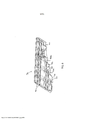
[0033] Nas modalidades da presente revelação, os meios de filtração em relevo 20 é, então, formado em um filtro, como filtro 60 mostrado nas figuras 4 a 6, tendo pelo menos uma primeira parte 62 e uma segunda parte 64 (também referida na presente invenção como parede no topo/superior e de base/inferior ou partes com base em sua orientação de instalação típica), tendo um formato fechado como um filtro estilo meia, onde o meio 20 é enrolado ou dobrado e as margens livres são vedadas juntas utilizando os processos conhecidos, para formar um espaço interior fechado. As áreas em relevo 50 criam a separação e a estrutura para manter as paredes superior e inferior 62, 64 dos meios de filtração separados enquanto o fluido flui através do filtro no tanque 60. As camadas em relevo do meio 20 têm a integridade estrutural e resistência a ser comprimida com um padrão em relevo profundo de 2 a 15 mm, ou 4 a 10 mm, ou cerca de 6mm, que possibilita a manutenção de um receptáculo (espaço interior 30) dentro do filtro para possibilitar o fluxo do fluido. Isto é, e como melhor visto na figura 6, a parede superior 62 e a parede inferior 64 estendem-se cada uma geralmente em um plano superior e inferior, e as áreas frusto-cônicas em relevo 50 projetam-se para dentro do respectivo plano em direção ao espaço interior 30 (e parede oposta) uma profundidade D (profundidade também referida na presente invenção como altura). Nos respectivos planos do meio 20, as áreas em relevo 50 têm uma largura W1 que é maior que uma largura W2 no pico da área em relevo 50. Dessa forma, o filtro não precisa incluir qualquer estrutura de suporte interna, pentes ou nervuras no espaço interior 30.[0033] In embodiments of the present disclosure, the raised filter means 20 is then formed into a filter, such as filter 60 shown in Figures 4 to 6, having at least a
[0034] As áreas em relevo 50 podem ter várias profundidades, larguras e comprimentos com base na espessura geral do meio 20, que tipicamente é 0,5 - 3,5 mm, e geralmente 1,5 a 2,5 mm. A profundidade em relevo D é variável, mas recomendada ser distanciada da superfície ou plano dos meios de filtração de pelo menos 2 mm e até 15 mm. Esta é apenas uma faixa comum de utilização e a profundidade poderia ser mais do que 15 mm sem qualquer efeito mensurável ou benefício, separação do meio ou rigidez do filtro. O índice da profundidade da gravação para a espessura do meio é preferivelmente 100% para 2000%, e mais preferivelmente maior que 300%. A área de cada parede superior e inferior 62, 64 é preferivelmente compreendida por 5% a 50% das áreas em relevo 50, e mais preferivelmente 10% a 20% embora qualquer porcentagem da área possa ser gravada enquanto ainda mantém o espaço interior 30 e fluxo do fluido. Conforme será ilustrado nas modalidades selecionadas, as áreas em relevo 50 podem ser diferentes nas partes superior e inferior 62, 64 do filtro 60, por exemplo, tanto no tamanho (largura ou profundidade), formato quanto posição relativa em um eixo vertical para possibilitar o fluxo de combustível através do receptáculo 30 através da combinação de áreas em relevo 50 nas paredes superior e inferior 62, 64.[0034]
[0035] O método de gravação da presente revelação inclui a criação de protrusões ou inchaços tendo vários tamanhos e formatos, ou seja, variando em largura e comprimentos, pontos em formato circular, quadrado, retangular ou oblongo ou pinos, cada um formando uma área em relevo 50 que é comprimida (por exemplo, espessura reduzida do meio 20) e esticada, pela qual os meios de filtração 20 cria deformações permanentes. Essas áreas deformadas permaneceriam contra os meios de filtração 20 no lado oposto do filtro, por exemplo, projetam dentro de um filtro no estilo meia e mantêm um receptáculo aberto 30 dentro do filtro para fluxo do fluido e fornecem rigidez ao filtro para fornecer uma estrutura de filtro e formato geométrico geral.[0035] The engraving method of the present disclosure includes creating protrusions or bumps having various sizes and shapes, i.e. varying in width and lengths, circular, square, rectangular or oblong shaped dots or pins, each forming an area in
[0036] Com referência novamente às figuras 4 a 6, as áreas em relevo 50 ilustradas são formadas como pontos em ambas as paredes superior e inferior 62, 64 do filtro 60 e fornecem separação entre o topo e a base do filtro 60 para manter o espaço interior 30 aberto. Declarado de outra forma, as áreas em relevo 50 são uma descontinuidade tendo um frusto-cônico. Essa gravação garante que o meio 20 não quebre contra as partes superior e inferior ou lados e reduzem ou bloqueiam o fluxo de fluido através do filtro 60. A figura 5 mostra o lado inferior do mesmo filtro 60 com as imagens do escalonamento dos pontos com relação aos lados superior e inferior do filtro. Isto é, os pontos em relevo 50 na parte superior 62 não são radialmente alinhados com relação a um eixo vertical (por exemplo, um eixo que passa pelo encaixe interno) com os pontos em relevo 50 da parte superior 64. Os pontos em relevo 50 em cada lado 62, 64 são preferivelmente espaçados em uma matriz ou grade. A figura 6 é um corte do mesmo filtro na figura 4 e na figura 5 e mostra como os pontos em relevo 50 fornecem um espaço de separação 66 entre as paredes superior e inferior 62, 64 do filtro 60.[0036] Referring again to Figures 4 to 6, the illustrated raised
[0037] Com referência à figura 7, uma implementação de um filtro 70 é mostrada tendo longas tiras de áreas em relevo 50t percorrendo o comprimento da parede superior 72 do filtro 70. Isto é, as áreas em relevo 50t têm um formato de canal e estendem-se lateralmente com relação a um eixo vertical (ou verticalmente em relação ao filtro 70). A figura 8 mostra a parede inferior 74 do filtro 70 com tiras em relevo 50b percorrendo na direção oposta (ou seja, em um ângulo com relação à direção das tiras em relevo superiores 50t, por exemplo, 90 graus) para fornecer formações rígidas que se pressionam entre si. A figura 9 é um corte do filtro 70 da figura 7 e da figura 8, e mostra como as áreas em relevo 50t, 50b fornecem um espaço de separação 76 entre as partes superior e inferior 72, 74 do filtro.[0037] Referring to Figure 7, an implementation of a filter 70 is shown having long strips of raised
[0038] Com referência à figura 10, uma implementação de um filtro 80 é mostrada tendo tiras mais curtas de áreas em relevo 50b em uma parede inferior 84 do filtro. Declarado de outra forma, as áreas em relevo 50b são essencialmente um ponto retangular. A figura 11 mostra a parede superior 82 do filtro 80, que não tem quaisquer áreas em relevo. A figura 12 é um corte do filtro 80 da figura 10 e da figura 11, e mostra como as áreas em relevo 50b fornecem um espaço de separação 86 entre as partes superior e inferior 82, 84 do filtro 80.[0038] Referring to Figure 10, an implementation of a filter 80 is shown having shorter strips of raised
[0039] Com referência à figura 13, uma implementação de um filtro 90 é mostrada tendo tiras curvadas das áreas em relevo 50t em uma parede superior 92 do filtro. A curvatura geralmente segue um padrão sinusoidal, embora outras curvaturas possam ser utilizadas. A figura 14 mostra a parede inferior 94 do filtro 90 com as áreas em relevo longas e retas 50b para fornecer formações rígidas que se definem contra as áreas em relevo superiores 50t. A figura 15 é um corte do filtro 90 da figura 13 e da figura 14 e mostra como as áreas em relevo 50t, 50b fornecem um espaço de separação 96 entre as partes superior e inferior 92, 94 do filtro 90. Isto é, onde as áreas em relevo superiores 50t se alinham com as áreas em relevo inferiores 50b, as áreas em relevo podem pressionar contra entre si para, ainda, manter o espaço interior 96.[0039] Referring to Figure 13, an implementation of a filter 90 is shown having curved strips of raised
[0040] Com referência à figura 16, uma implementação de um filtro 100 é mostrada tendo áreas em relevo 50t na parede superior 102 do filtro 100 que tem uma profundidade maior que a altura do espaço interior 106. Isto é, as áreas em relevo 50t têm uma profundidade de modo que elas se empurram para dentro da parede inferior 104 e deformam as partes correspondentes da parede inferior 104 para baixo de um plano da parede inferior 104 para formar as protrusões 108. Dessa forma, as protrusões 108 podem agir como pés para manter o restante da parede inferior 104 fora da base do tanque (como em um tanque de combustível), possibilitando, assim, o fluxo do fluido através de todas as superfícies do filtro 100.[0040] Referring to Fig. 16, an implementation of a filter 100 is shown having raised
[0041] Áreas adicionais de aplicabilidade se tornarão evidentes a partir do da descrição fornecida na presente invenção. Deve ser entendido que a descrição e exemplos específicos são destinados para finalidades de ilustração apenas e não se destinam a limitar o escopo da presente revelação.[0041] Additional areas of applicability will become apparent from the description provided in the present invention. It is to be understood that the description and specific examples are intended for purposes of illustration only and are not intended to limit the scope of the present disclosure.
[0042] As modalidades descritas devem ser consideradas em todos os aspectos apenas como ilustrativas e não restritivas. O escopo da invenção é, portanto, indicado pelas reivindicações anexas em vez de pela descrição supracitada. Todas as mudanças que estão dentro do significado e faixa de equivalência das reivindicações devem ser abrangidas dentro de seu escopo.[0042] The described modalities are to be considered in all respects only as illustrative and not restrictive. The scope of the invention is therefore indicated by the appended claims rather than the above-cited description. All changes that are within the meaning and range of equivalence of the claims must be covered within their scope.
Claims (21)
Applications Claiming Priority (3)
| Application Number | Priority Date | Filing Date | Title |
|---|---|---|---|
| US201462001922P | 2014-05-22 | 2014-05-22 | |
| US62/001,922 | 2014-05-22 | ||
| PCT/US2015/032244 WO2015179800A1 (en) | 2014-05-22 | 2015-05-22 | Forming filtration media for maintaining flow passage through a sock style filter |
Publications (2)
| Publication Number | Publication Date |
|---|---|
| BR112016027296A2 BR112016027296A2 (en) | 2017-08-15 |
| BR112016027296B1 true BR112016027296B1 (en) | 2022-04-19 |
Family
ID=54554857
Family Applications (1)
| Application Number | Title | Priority Date | Filing Date |
|---|---|---|---|
| BR112016027296-0A BR112016027296B1 (en) | 2014-05-22 | 2015-05-22 | Filter for a suction system |
Country Status (8)
| Country | Link |
|---|---|
| US (1) | US9937448B2 (en) |
| EP (1) | EP3145611B1 (en) |
| JP (1) | JP6363793B2 (en) |
| CN (1) | CN106488794B (en) |
| BR (1) | BR112016027296B1 (en) |
| MX (1) | MX2016015300A (en) |
| PL (1) | PL3145611T3 (en) |
| WO (1) | WO2015179800A1 (en) |
Families Citing this family (9)
| Publication number | Priority date | Publication date | Assignee | Title |
|---|---|---|---|---|
| US10029561B2 (en) | 2014-11-07 | 2018-07-24 | Holley Performance Products, Inc. | Liquid reservoir system and method |
| US9796259B2 (en) | 2015-12-14 | 2017-10-24 | Holley Performance Products, Inc. | Systems and methods for installing and sealing fuel pump in fuel tank |
| US20170173500A1 (en) * | 2015-12-21 | 2017-06-22 | Kuss Filtration Inc. | Filter with flexible ribs |
| EP3568224B8 (en) * | 2017-01-13 | 2022-09-28 | GVS Filtration Inc. | Method of manufacturing a fluid filter |
| US20220054969A1 (en) * | 2018-09-28 | 2022-02-24 | Daikin Industries, Ltd. | Air filter medium, filter pack, air filter unit, and methods for producing them |
| DE102019202136A1 (en) * | 2019-02-18 | 2020-08-20 | Siemens Mobility GmbH | Arrangement for filtering liquids |
| KR102178858B1 (en) * | 2019-09-25 | 2020-11-13 | 주식회사 코아비스 | Strainer of fuel pump |
| KR20210137607A (en) * | 2020-05-11 | 2021-11-18 | 삼성전자주식회사 | Vacuum cleaner and dies apparatus |
| CH718256A1 (en) * | 2020-11-16 | 2022-07-15 | Mueller Drm Ag | Filter element for separating solids from liquids or gases. |
Family Cites Families (18)
| Publication number | Priority date | Publication date | Assignee | Title |
|---|---|---|---|---|
| GB586428A (en) * | 1945-05-31 | 1947-03-18 | Samuel Alsop | Improvement in filters |
| US4304664A (en) * | 1980-05-05 | 1981-12-08 | General Motors Corporation | Fuel strainer assembly |
| EP1172134A1 (en) * | 1996-02-01 | 2002-01-16 | Toyo Roki Seizo Kabushikikaisha | Filter and filter medium unit for use therein |
| US5902480A (en) | 1997-05-13 | 1999-05-11 | Kuss Corporation | Depth media in-tank fuel filter with extruded mesh shell |
| US6273938B1 (en) * | 1999-08-13 | 2001-08-14 | 3M Innovative Properties Company | Channel flow filter |
| JP4470079B2 (en) * | 2000-03-23 | 2010-06-02 | 東洋紡績株式会社 | Air purification filter |
| JP2002028408A (en) * | 2000-07-18 | 2002-01-29 | Kyosan Denki Co Ltd | Filter |
| JP2002186809A (en) * | 2000-12-20 | 2002-07-02 | Toyoda Spinning & Weaving Co Ltd | Filter and method for manufacturing the same |
| JP4559667B2 (en) * | 2001-07-16 | 2010-10-13 | 株式会社ニフコ | Fuel filter device |
| US20030010692A1 (en) | 2001-07-16 | 2003-01-16 | Hiroji Sato | Fuel-filtering device |
| JP2003126619A (en) * | 2001-10-29 | 2003-05-07 | Kyosan Denki Co Ltd | Fuel filter |
| DE10317853A1 (en) * | 2003-04-16 | 2004-11-04 | A3 Abfall-Abwasser-Anlagentechnik Gmbh | filtration module |
| US20050045566A1 (en) * | 2003-08-29 | 2005-03-03 | Larry Larkin | Filtration media created by sonic welding |
| JP2005087930A (en) * | 2003-09-19 | 2005-04-07 | Kyosan Denki Co Ltd | Filter |
| JP4615377B2 (en) * | 2005-06-03 | 2011-01-19 | パナソニック株式会社 | Regenerated processing filter for used cooking oil and fat, and reprocessing apparatus using the same |
| US7625418B1 (en) * | 2005-06-08 | 2009-12-01 | Aaf-Mcquay, Inc. | Spacer arrangement for pleated filter |
| DE102010011785A1 (en) * | 2010-03-17 | 2011-09-22 | Mann+Hummel Gmbh | Device for folding a web-shaped filter medium and method for producing a zigzag-folded filter element |
| JP5602521B2 (en) * | 2010-07-02 | 2014-10-08 | ニッタ株式会社 | Air filter insert |
-
2015
- 2015-05-22 JP JP2017514389A patent/JP6363793B2/en active Active
- 2015-05-22 MX MX2016015300A patent/MX2016015300A/en unknown
- 2015-05-22 PL PL15795779T patent/PL3145611T3/en unknown
- 2015-05-22 EP EP15795779.6A patent/EP3145611B1/en active Active
- 2015-05-22 WO PCT/US2015/032244 patent/WO2015179800A1/en active Application Filing
- 2015-05-22 US US14/720,322 patent/US9937448B2/en active Active
- 2015-05-22 BR BR112016027296-0A patent/BR112016027296B1/en active IP Right Grant
- 2015-05-22 CN CN201580036893.8A patent/CN106488794B/en active Active
Also Published As
| Publication number | Publication date |
|---|---|
| JP6363793B2 (en) | 2018-07-25 |
| MX2016015300A (en) | 2017-05-09 |
| WO2015179800A1 (en) | 2015-11-26 |
| CN106488794A (en) | 2017-03-08 |
| EP3145611A4 (en) | 2018-02-07 |
| EP3145611B1 (en) | 2020-08-26 |
| PL3145611T3 (en) | 2021-03-08 |
| JP2017516657A (en) | 2017-06-22 |
| US9937448B2 (en) | 2018-04-10 |
| US20160339363A1 (en) | 2016-11-24 |
| BR112016027296A2 (en) | 2017-08-15 |
| EP3145611A1 (en) | 2017-03-29 |
| CN106488794B (en) | 2019-07-19 |
Similar Documents
| Publication | Publication Date | Title |
|---|---|---|
| BR112016027296B1 (en) | Filter for a suction system | |
| EP3570798A1 (en) | Porous wound insert for use in negative pressure therapy | |
| KR101484031B1 (en) | Human implantable tissue expander | |
| US9314717B2 (en) | Embossed fluid filter element | |
| ES2674573T3 (en) | Configuration of contact fixing products faces | |
| ES2577953T3 (en) | Closing device for sachets or equivalents that has an improved touch and sound effect, sachet thus obtained and procedure for carrying out | |
| CN106973567A (en) | Filter and filter cylinder | |
| BRPI0904272A2 (en) | transfer layer for absorbent articles | |
| KR101571291B1 (en) | Bio-puncture needle and manufacturing method thereof | |
| BR112012033246B1 (en) | tread protection device | |
| JP2015513425A5 (en) | ||
| BR102014019854B1 (en) | tire tread with transverse grooves and blade for molding a tire tread | |
| JP5107000B2 (en) | Filter unit panel and manufacturing method thereof | |
| JP2007021577A (en) | Deep drawn sink and deep drawing process | |
| BR112021010216A2 (en) | 3d printed filter center tube | |
| DE102014005190A1 (en) | Interior trim part with a flat heating element and method for its production | |
| ES2379232T3 (en) | Insertion block for the formation of a field of hooks in an injection molded object and molded object comprising a field of hooks of this type | |
| CN103476475B (en) | Filter | |
| JP2011148235A (en) | Mold for molding tire, and pneumatic tire | |
| WO2016130948A1 (en) | Weatherstrip having undulating base | |
| BR112017028498B1 (en) | DEBURNING METHOD AND DEBURING SYSTEM | |
| EP3116560A1 (en) | Blood treatment cartridge with a film valve and nonelastic spacer, and blood treatment device | |
| JP6552927B2 (en) | Pneumatic tire | |
| JP7117065B2 (en) | Press mold and its manufacturing method | |
| EP2862491A1 (en) | Adapter plate for dust filter bags |
Legal Events
| Date | Code | Title | Description |
|---|---|---|---|
| B06U | Preliminary requirement: requests with searches performed by other patent offices: procedure suspended [chapter 6.21 patent gazette] | ||
| B350 | Update of information on the portal [chapter 15.35 patent gazette] | ||
| B09A | Decision: intention to grant [chapter 9.1 patent gazette] | ||
| B16A | Patent or certificate of addition of invention granted [chapter 16.1 patent gazette] |
Free format text: PRAZO DE VALIDADE: 20 (VINTE) ANOS CONTADOS A PARTIR DE 22/05/2015, OBSERVADAS AS CONDICOES LEGAIS. |