BR112015032926B1 - ULTRASOUND THERAPY SYSTEM - Google Patents
ULTRASOUND THERAPY SYSTEM Download PDFInfo
- Publication number
- BR112015032926B1 BR112015032926B1 BR112015032926-8A BR112015032926A BR112015032926B1 BR 112015032926 B1 BR112015032926 B1 BR 112015032926B1 BR 112015032926 A BR112015032926 A BR 112015032926A BR 112015032926 B1 BR112015032926 B1 BR 112015032926B1
- Authority
- BR
- Brazil
- Prior art keywords
- bubble
- pressure
- tissue
- ultrasound therapy
- pulse
- Prior art date
Links
Images


Classifications
-
- A—HUMAN NECESSITIES
- A61—MEDICAL OR VETERINARY SCIENCE; HYGIENE
- A61N—ELECTROTHERAPY; MAGNETOTHERAPY; RADIATION THERAPY; ULTRASOUND THERAPY
- A61N7/00—Ultrasound therapy
-
- A—HUMAN NECESSITIES
- A61—MEDICAL OR VETERINARY SCIENCE; HYGIENE
- A61B—DIAGNOSIS; SURGERY; IDENTIFICATION
- A61B17/00—Surgical instruments, devices or methods, e.g. tourniquets
- A61B17/22—Implements for squeezing-off ulcers or the like on the inside of inner organs of the body; Implements for scraping-out cavities of body organs, e.g. bones; Calculus removers; Calculus smashing apparatus; Apparatus for removing obstructions in blood vessels, not otherwise provided for
- A61B17/22004—Implements for squeezing-off ulcers or the like on the inside of inner organs of the body; Implements for scraping-out cavities of body organs, e.g. bones; Calculus removers; Calculus smashing apparatus; Apparatus for removing obstructions in blood vessels, not otherwise provided for using mechanical vibrations, e.g. ultrasonic shock waves
-
- A—HUMAN NECESSITIES
- A61—MEDICAL OR VETERINARY SCIENCE; HYGIENE
- A61B—DIAGNOSIS; SURGERY; IDENTIFICATION
- A61B17/00—Surgical instruments, devices or methods, e.g. tourniquets
- A61B17/22—Implements for squeezing-off ulcers or the like on the inside of inner organs of the body; Implements for scraping-out cavities of body organs, e.g. bones; Calculus removers; Calculus smashing apparatus; Apparatus for removing obstructions in blood vessels, not otherwise provided for
- A61B17/225—Implements for squeezing-off ulcers or the like on the inside of inner organs of the body; Implements for scraping-out cavities of body organs, e.g. bones; Calculus removers; Calculus smashing apparatus; Apparatus for removing obstructions in blood vessels, not otherwise provided for for extracorporeal shock wave lithotripsy [ESWL], e.g. by using ultrasonic waves
-
- A—HUMAN NECESSITIES
- A61—MEDICAL OR VETERINARY SCIENCE; HYGIENE
- A61B—DIAGNOSIS; SURGERY; IDENTIFICATION
- A61B17/00—Surgical instruments, devices or methods, e.g. tourniquets
- A61B2017/00017—Electrical control of surgical instruments
- A61B2017/00137—Details of operation mode
- A61B2017/00154—Details of operation mode pulsed
- A61B2017/00172—Pulse trains, bursts, intermittent continuous operation
- A61B2017/00176—Two pulses, e.g. second pulse having an effect different from the first one
-
- A—HUMAN NECESSITIES
- A61—MEDICAL OR VETERINARY SCIENCE; HYGIENE
- A61B—DIAGNOSIS; SURGERY; IDENTIFICATION
- A61B17/00—Surgical instruments, devices or methods, e.g. tourniquets
- A61B17/22—Implements for squeezing-off ulcers or the like on the inside of inner organs of the body; Implements for scraping-out cavities of body organs, e.g. bones; Calculus removers; Calculus smashing apparatus; Apparatus for removing obstructions in blood vessels, not otherwise provided for
- A61B17/22004—Implements for squeezing-off ulcers or the like on the inside of inner organs of the body; Implements for scraping-out cavities of body organs, e.g. bones; Calculus removers; Calculus smashing apparatus; Apparatus for removing obstructions in blood vessels, not otherwise provided for using mechanical vibrations, e.g. ultrasonic shock waves
- A61B2017/22005—Effects, e.g. on tissue
- A61B2017/22007—Cavitation or pseudocavitation, i.e. creation of gas bubbles generating a secondary shock wave when collapsing
- A61B2017/22008—Cavitation or pseudocavitation, i.e. creation of gas bubbles generating a secondary shock wave when collapsing used or promoted
-
- A—HUMAN NECESSITIES
- A61—MEDICAL OR VETERINARY SCIENCE; HYGIENE
- A61B—DIAGNOSIS; SURGERY; IDENTIFICATION
- A61B17/00—Surgical instruments, devices or methods, e.g. tourniquets
- A61B17/22—Implements for squeezing-off ulcers or the like on the inside of inner organs of the body; Implements for scraping-out cavities of body organs, e.g. bones; Calculus removers; Calculus smashing apparatus; Apparatus for removing obstructions in blood vessels, not otherwise provided for
- A61B17/22004—Implements for squeezing-off ulcers or the like on the inside of inner organs of the body; Implements for scraping-out cavities of body organs, e.g. bones; Calculus removers; Calculus smashing apparatus; Apparatus for removing obstructions in blood vessels, not otherwise provided for using mechanical vibrations, e.g. ultrasonic shock waves
- A61B2017/22027—Features of transducers
- A61B2017/22028—Features of transducers arrays, e.g. phased arrays
-
- A—HUMAN NECESSITIES
- A61—MEDICAL OR VETERINARY SCIENCE; HYGIENE
- A61N—ELECTROTHERAPY; MAGNETOTHERAPY; RADIATION THERAPY; ULTRASOUND THERAPY
- A61N7/00—Ultrasound therapy
- A61N2007/0039—Ultrasound therapy using microbubbles
-
- A—HUMAN NECESSITIES
- A61—MEDICAL OR VETERINARY SCIENCE; HYGIENE
- A61N—ELECTROTHERAPY; MAGNETOTHERAPY; RADIATION THERAPY; ULTRASOUND THERAPY
- A61N7/00—Ultrasound therapy
- A61N2007/0078—Ultrasound therapy with multiple treatment transducers
Abstract
sequências de excitação de histotripsia otimizadas para a formação de nuvem de bolha ao usar dispersão de choque. a presente invenção refere-se a métodos e dispositivos para a produção de cavitação em tecido. em uma modalidade, um método de dispersão de choque de terapia de histotripsia compreende a aplicação de uma forma de onda de pressão de iniciação de um transdutor de terapia de ultrassom em tecido, em que a forma de onda de pressão de iniciação é configurada para produzir pelo menos uma bolha no tecido, a aplicação de uma forma de onda de pressão de dispersão do transdutor de terapia de ultrassom em pelo menos uma bolha dentro de um ciclo de vida de pelo menos uma bolha, e a produção de núcleos da cavitação perto de pelo menos uma bolha com a forma de onda de pressão de dispersão. a forma de onda de pressão de dispersão pode ser aplicada durante o ciclo de vida de pelo menos uma bolha. em algumas modalidades, a forma de onda de pressão de dispersão é aplicado dentro 5 µs a 1 s do forma de onda de pressão de iniciação. os sistemas para executar a terapia de histotripsia de dispersão de choque também são discutidos.histotripsy excitation sequences optimized for bubble cloud formation when using shock scattering. the present invention relates to methods and devices for producing tissue cavitation. in one embodiment, a shock scattering method of histotripsy therapy comprises applying an initiating pressure waveform from an ultrasound therapy transducer to tissue, wherein the initiating pressure waveform is configured to produce at least one bubble in the tissue, applying a scattering pressure waveform from the ultrasound therapy transducer to at least one bubble within a life cycle of at least one bubble, and producing cavitation nuclei close to at least one bubble with the dispersion pressure waveform. the scattering pressure waveform can be applied during the life cycle of at least one bubble. in some embodiments, the dispersion pressure waveform is applied within 5 µs to 1 s of the initiating pressure waveform. systems for performing shock dispersion histotripsy therapy are also discussed.
Description
[001] O presente pedido de patente reivindica o benefício sob 35 U.S.C.119 do Pedido de Patente Provisório U.S. no. 61/842.820, depositado em 03 de julho de 2013, intitulado "Sequências de Excitação Modulada Para a Terapia Cavitacional de Ultrassom Pulsado Intensificada", pedido esse que é incorporado a título de referência no presente documento.[001] The present patent application claims benefit under 35 U.S.C.119 of the U.S. Provisional Patent Application. at the. 61/842,820, filed July 3, 2013, entitled "Modulated Excitation Sequences for Cavitational Pulsed Ultrasound Intensified Therapy", which application is incorporated by reference herein.
[002] Todas as publicações e pedidos de patente mencionados neste relatório descritivo estão incorporados no presente documento a título de referência até a mesma extensão em que cada publicação ou pedido de patente individual foi indicado específica e individualmente para ser incorporado a título de referência.[002] All publications and patent applications mentioned in this specification are hereby incorporated by reference to the same extent to which each individual publication or patent application was specifically and individually indicated to be incorporated by reference.
[003] A presente invenção refere-se de modo geral ao tratamento de tecido com a cavitação criada pela terapia de ultrassom.[003] The present invention generally relates to the treatment of tissue with the cavitation created by ultrasound therapy.
[004] A histotripsia, ou terapia de cavitação de ultrassom pulsado, é uma tecnologia em que surtos intensos curtos da energia acústica induzem a cavitação controlada (formação de microbolhas ou nuvem de bolhas) dentro do volume focal. A expansão vigorosa e o colapso dessas microbolhas homogeniza mecanicamente as células e estruturas de tecidos dentro do volume focal. Este é um resultado final muito diferente do que a necrose coagulativa característica da ablação térmica. Para operar dentro de um ambiente de histotripsia não térmico, é necessário aplicar a energia acústica na forma de pulsos acústicos de amplitude a alta pressão com baixo ciclo de trabalho.[004] Histotripsy, or pulsed ultrasound cavitation therapy, is a technology in which short intense bursts of acoustic energy induce controlled cavitation (microbubble formation or cloud of bubbles) within the focal volume. The vigorous expansion and collapse of these microbubbles mechanically homogenizes the cells and tissue structures within the focal volume. This is a very different end result than the coagulative necrosis characteristic of thermal ablation. To operate within a non-thermal histotripsy environment, it is necessary to apply acoustic energy in the form of high-pressure amplitude acoustic pulses with low duty cycle.
[005] Em comparação com as tecnologias de ultrassom focaliza do convencionais, a histotripsia tem vantagens importantes: 1) o processo destrutivo no foco é mecânico e não térmico; 2) as nuvens de bolhas aparecem brilhantes na imagem de ultrassom, confirmando desse modo o foco e a localização corretos do tratamento; 3) o tecido tratado aparece mais escuro (hipoecoico) na imagem de ultrassom, de modo que o operador saiba o que foi tratado; e 4) a histotripsia produz lesões de uma maneira controlada e precisa. É importante enfatizar o fato que, ao contrário da micro-onda, radiofrequência ou ultrassom focalizado de alta intensidade (HIFU), a histotripsia não é uma modalidade térmica.[005] Compared with conventional focus ultrasound technologies, histotripsy has important advantages: 1) the destructive process in the focus is mechanical and not thermal; 2) the bubble clouds appear bright on the ultrasound image, thereby confirming the correct focus and location of the treatment; 3) the treated tissue appears darker (hypoechoic) on the ultrasound image, so the operator knows what has been treated; and 4) histotripsy produces lesions in a controlled and precise manner. It is important to emphasize the fact that, unlike microwave, radiofrequency, or high-intensity focused ultrasound (HIFU), histotripsy is not a thermal modality.
[006] Os estudos iniciais em cães de homogeneização de Histo- tripsia do tecido da próstata empregaram um transdutor de terapia que foi posicionado para aplicar a histotripsia transabdominalmente. Nesses estudos, a próstata foi localizada somente a uma curta distância da superfície da pele e havia uma passagem relativamente larga do transdutor através da pele para focalizar a energia de ultrassom. Consequentemente, o transdutor esférico da terapia de histotripsia empregado nesses estudos tinha uma abertura de 14 cm e um comprimento focal de 10 cm (F-número = 0,71). Os transdutores de terapia de histo- tripsia com F-números elevados têm uma eficiência muito baixa em comparação aos transdutores com F-números baixos. Essas ineficiências são principalmente devido à propagação acústica não linear que conduz à formação de ondas de choque.[006] Initial studies in dogs of Histotripsy homogenization of prostate tissue employed a therapy transducer that was positioned to deliver histotripsy transabdominally. In these studies, the prostate was located only a short distance from the surface of the skin and there was a relatively wide passage of the transducer through the skin to focus the ultrasound energy. Consequently, the spherical histotripsy therapy transducer employed in these studies had an aperture of 14 cm and a focal length of 10 cm (F-number = 0.71). High F-number histotripsy therapy transducers have very low efficiency compared to low F-number transducers. These inefficiencies are mainly due to nonlinear acoustic propagation leading to the formation of shock waves.
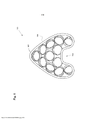
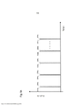
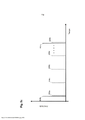
[007] A eletrônica de transdutor e acionador de terapia especiali zada foi projetada para focalizar a terapia de histotripsia através do períneo até a próstata. Um exemplo de um transdutor de terapia 100 configurado para aplicar a terapia de histotripsia à próstata é mostrado na Figura 1. O transdutor 100 pode compreender uma pluralidade de elementos de transdutor de ultrassom 102 dispostos dentro do invólu- cro 104. O transdutor pode ser conectado a um gerador de formas de onda configurado para aplicar formas de ondas de histotripsia do transdutor ao tecido. A profundidade da próstata desta abordagem é significativamente mais profunda do que no modelo canino acima. Além disso, a anatomia esqueletal da pelve e a posição transretal da sonda da imagem de ultrassom reduziram de maneira significativa a abertura eficaz do transdutor. Um entalhe 106 no perímetro inferior do invólucro pode ser configurado para acomodar uma sonda de imagem de ultrassom (não mostrada) que tem um F-número = 0,85 no diâmetro principal e um F-número = 0,98 no entalhe.[007] Specialized therapy transducer and trigger electronics are designed to focus histotripsy therapy through the perineum to the prostate. An example of a
[008] Com base na experimentação de topo de bancada e em modelagem, um conjunto inicial de parâmetros de excitação de transdutor da terapia (3 ciclos/pulso, 750 Vpp, 500 Hz PRF (Frequência de Repetição de Pulso)) foi selecionado para o teste canino com esse transdutor. Essa sequência de excitação produziu um forma de onda de pressão focal não linear com uma pressão de pico negativo e de pico positivo de cerca de 25 MPa e 100 MPa na água. Foi aqui definida essa sequência e suas variantes como uma sequência padrão, ou não otimizada, porque os parâmetros da sequência não foram otimizados para a formação da nuvem de bolhas.[008] Based on bench top experimentation and modeling, an initial set of therapy transducer excitation parameters (3 cycles/pulse, 750 Vpp, 500 Hz PRF (Pulse Repetition Frequency)) was selected for the canine test with this transducer. This excitation sequence produced a nonlinear focal pressure waveform with a peak negative and peak positive pressure of about 25 MPa and 100 MPa in water. This sequence and its variants were defined here as a standard sequence, or not optimized, because the sequence parameters were not optimized for the formation of the bubble cloud.
[009] Essa sequência de excitação padrão e as variantes foram usados no tratamento de cerca de 30 indivíduos caninos para estabelecer a praticabilidade, a dosagem (número cumulativo de pulsos), e as diretrizes de implementação do tratamento. Mais 10 indivíduos caninos foram tratados então em um estudo confirmatório. Embora esses estudos acarretassem resultados de eficácia proeminente, a observação de pequenos ferimentos aparentes (fibrose subclinica) ao músculo do reto abdominal pré-focal em 2 de 10 indivíduos na experimentação confirmatória conduziu à conclusão que o perfil de segurança precisou ser melhorado por meio do desenvolvimento de sequências de pulsos de histotripsia que aplicam a energia mais eficientemente. É provável que a necessidade de melhorar a eficiência da histotripsia tornar-se-á mais importante à medida que os transdutores forem desenvolvidos para penetrar mais fundo nos tecidos através de obstruções anatômicas esqueletais.[009] This standard arousal sequence and variants were used in the treatment of approximately 30 canine subjects to establish practicability, dosing (cumulative number of pulses), and treatment implementation guidelines. A further 10 canine subjects were then treated in a confirmatory study. Although these studies yielded outstanding efficacy results, the observation of apparent minor injury (subclinical fibrosis) to the prefocal rectus abdominis muscle in 2 of 10 subjects in the confirmatory trial led to the conclusion that the safety profile needed to be improved through the development of sequences of histotripsy pulses that apply energy more efficiently. It is likely that the need to improve the efficiency of histotripsy will become more important as transducers are developed to penetrate deeper into tissues through skeletal anatomic obstructions.
[0010] A eficiência aprimorada que conduz à redução de calor pré- focal é imperativa quando o tecido mole é visado profundamente abaixo da superfície da pele através de obstruções anatômicas esqueletais que requerem transdutores de terapia de ultrassom que têm números F relativamente elevados (F-número > 0,8). As sequências otimizadas para a homogeneização de histotripsia intensificada de tecidos moles foram desenvolvidas para reduzir o potencial de ferimento térmico pré- focal mediante a otimização da eficiência das sequências. A eficiência melhorada de sequências de excitação otimizadas aumenta a probabilidade de iniciar nuvens de bolhas de histotripsia no tecido e reduz as ocorrências de extinção de nuvens de bolhas quando da translação através de tecidos. Além disso, as sequências otimizadas podem ser projetadas para a ablação seletiva de tecidos fibrosos ou a ablação de tecidos menos densos enquanto são preservadas as estruturas vitais mais fibroelásticas tais como estruturas neuro-vasculares.[0010] Improved efficiency leading to prefocal heat reduction is imperative when soft tissue is targeted deep below the skin surface through skeletal anatomical obstructions that require ultrasound therapy transducers that have relatively high F numbers (F- number > 0.8). Optimized sequences for intensified soft tissue histotripsy homogenization were developed to reduce the potential for prefocal thermal injury by optimizing sequence efficiency. The improved efficiency of optimized excitation sequences increases the probability of initiating histotripsy bubble clouds in tissue and reduces the occurrences of bubble cloud extinction when translating through tissues. Furthermore, optimized sequences can be designed for selective ablation of fibrous tissues or ablation of less dense tissues while preserving more fibroelastic vital structures such as neurovascular structures.
[0011] As sequências otimizadas eficazes para transdutores de F- números elevados são caracterizadas por um pulso de iniciação que é projetado para criar um menos um único núcleo acusticamente gerado (bolha), seguido por um pulso de dispersão de choque (indicado daqui por diante como um pulso de dispersão ou forma de onda de pressão de dispersão) depois de um retardo de tempo otimizado para permitir que uma onda de choque colida sobre a primeira bolha para criar uma nuvem de bolhas. Os pulsos de dispersão subsequentes também podem seguir com o sincronismo otimizado a fim de manter ainda a efi- cácia da nuvem de bolhas. Deve ser observado que a forma de onda do pulso e da pressão será usada intercambiavelmente neste pedido de patente.[0011] Effective optimized sequences for high F-number transducers are characterized by an initiation pulse that is designed to create a minus a single acoustically generated nucleus (bubble), followed by a shock dispersion pulse (indicated hereinafter as a scatter pulse or scatter pressure waveform) after an optimized time delay to allow a shock wave to impinge on the first bubble to create a cloud of bubbles. Subsequent scatter pulses can also follow with optimal timing in order to still maintain bubble cloud effectiveness. It should be noted that pulse and pressure waveform will be used interchangeably in this patent application.
[0012] Um método de tratamento de tecido com a energia de ul trassom, o qual compreende as etapas de aplicação de uma forma de onda de pressão de iniciação de um transdutor de terapia de ultrassom no tecido, em que a forma de onda de pressão de iniciação é configurada para produzir pelo menos uma bolha no tecido, aplicação de uma forma de onda de pressão de dispersão do transdutor de terapia de ultrassom em pelo menos uma bolha dentro de um ciclo de vida de pelo menos uma bolha, e produção de núcleos de cavitação perto de pelo menos uma bolha com a forma de onda de pressão de dispersão.[0012] A method of treating tissue with ultrasound energy, which comprises the steps of applying an initiating pressure waveform from an ultrasound therapy transducer to tissue, wherein the pressure waveform priming is configured to produce at least one bubble in the tissue, applying a scattering pressure waveform from the ultrasound therapy transducer to at least one bubble within a life cycle of at least one bubble, and producing nuclei of cavitation near at least one bubble with the scattering pressure waveform.
[0013] Em algumas modalidades, a forma de onda de pressão de dispersão é aplicada dentro de 5 μs a 200 μs da forma de onda de pressão de iniciação.[0013] In some embodiments, the dispersion pressure waveform is applied within 5 µs to 200 µs of the initiation pressure waveform.
[0014] Em uma modalidade, o método também compreende a re petição das etapas de aplicação de uma forma de onda de pressão de iniciação e de aplicação de uma forma de onda de pressão de dispersão até que o tratamento do tecido esteja terminado.[0014] In one embodiment, the method also comprises repeating the steps of applying an initiating pressure waveform and applying a dispersing pressure waveform until the tissue treatment is completed.
[0015] Em uma modalidade, uma amplitude de pressão e/ou um número de ciclos da forma de onda de pressão de iniciação são minimizados para reduzir o aquecimento do tecido.[0015] In one embodiment, a pressure amplitude and/or a number of cycles of the initiation pressure waveform are minimized to reduce tissue heating.
[0016] Em uma outra modalidade, uma pressão pico a pico da forma de onda de pressão de dispersão é suficiente na amplitude para criar núcleos adicionais de cavitação na região focal.[0016] In another embodiment, a peak-to-peak pressure scattering pressure waveform is sufficient in amplitude to create additional nuclei of cavitation in the focal region.
[0017] Em modalidades alternativas, a amplitude de pressão e/ou o número dos ciclos de forma de onda de pressão de dispersão são minimizados para reduzir o aquecimento do tecido.[0017] In alternative embodiments, the pressure amplitude and/or the number of cycles of dispersion pressure waveform are minimized to reduce tissue heating.
[0018] Em algumas modalidade, o método também compreende, depois da aplicação da forma de onda de pressão de dispersão, a aplicação de uma segunda forma de onda de pressão de dispersão para pelo menos uma bolha e os núcleos de cavitação.[0018] In some embodiments, the method also comprises, after applying the scattering pressure waveform, applying a second scattering pressure waveform to at least one bubble and the cavitation nuclei.
[0019] Em algumas modalidades, a segunda forma de onda de pressão de dispersão é aplicada dentro de 5 μs a 1 s da forma de onda de pressão de dispersão.[0019] In some embodiments, the second dispersion pressure waveform is applied within 5 μs to 1 s of the dispersion pressure waveform.
[0020] Em uma outra modalidade, o método também compreende a aplicação de formas de ondas adicionais de pressão de dispersão sem a aplicação de formas de ondas de pressão de iniciação adicionais até que pelo menos uma bolha e/ou núcleos de cavitação não permaneçam mais no tecido.[0020] In another embodiment, the method also comprises applying additional dispersing pressure waveforms without applying additional initiating pressure waveforms until at least one bubble and/or cavitation nuclei no longer remain. in the fabric.
[0021] Em algumas modalidades, os formas de ondas de pressão de dispersão adicionais são aplicadas a cada 5 μs a 1 s.[0021] In some embodiments, additional dispersion pressure waveforms are applied every 5 μs to 1 s.
[0022] Em uma modalidade, uma sequência de pulso que compre ende a forma de onda de pressão de iniciação e a forma de onda de pressão de dispersão tem uma PRF de sequência que varia de 1 a 5.000 Hz.[0022] In one embodiment, a pulse sequence comprising the initiating pressure waveform and the scattering pressure waveform has a sequence PRF ranging from 1 to 5000 Hz.
[0023] Em outras modalidades, a forma de onda de pressão de dispersão aplica menos energia ao tecido intermediário do que a forma de onda de pressão de iniciação.[0023] In other embodiments, the dispersing pressure waveform applies less energy to the intermediate tissue than the initiating pressure waveform.
[0024] Em uma modalidade, a forma de onda de pressão de inicia ção e a forma de onda de pressão de dispersão têm amplitudes de pressão substancialmente similares. Em uma outra modalidade, uma amplitude de pressão da forma de onda de pressão de dispersão é menor do que uma amplitude de pressão da forma de onda de pressão de iniciação. Em modalidades alternativas, uma amplitude de pressão da forma de onda de pressão de dispersão é maior do que uma amplitude de pressão da forma de onda de pressão de iniciação.[0024] In one embodiment, the initiating pressure waveform and the dispersing pressure waveform have substantially similar pressure amplitudes. In another embodiment, a pressure amplitude of the scattering pressure waveform is less than a pressure amplitude of the initiating pressure waveform. In alternative embodiments, a pressure amplitude of the scattering pressure waveform is greater than a pressure amplitude of the initiating pressure waveform.
[0025] É provido um método de tratamento de tecido com a ener gia do ultrassom, o qual compreende as etapas de transmissão de uma forma de onda de pressão de iniciação de um transdutor de tera- pia de ultrassom no tecido, em que a forma de onda de pressão de iniciação é configurada para produzir pelo menos uma bolha no tecido, durante um ciclo de vida de pelo menos uma bolha, transmissão de uma forma de onda de pressão de dispersão do transdutor de terapia de ultrassom em pelo menos uma bolha, em que a forma de onda de pressão de dispersão é configurada para se transformar em uma forma de onda de pressão focal chocada no tecido que tem um meio ciclo de pressão positiva chocada e um meio ciclo de pressão negativa chocada, em que o meio ciclo de pressão positiva chocada é configurado para colidir pelo menos em uma bolha e para dispersar, inverter e interferir de modo construtivo com o meio ciclo de pressão negativa chocada para formar uma forma de onda de meio ciclo de pressão negativa, e produzir núcleos de cavitação perto de pelo menos uma bolha com um mecanismo de dispersão de choque entre a forma de onda de meio ciclo de pressão positiva e pelo menos uma bolha.[0025] A method of treating tissue with ultrasound energy is provided, which comprises the steps of transmitting an initiating pressure waveform from an ultrasound therapy transducer to tissue, wherein the form initiating pressure waveform is configured to produce at least one bubble in the tissue, during a life cycle of at least one bubble, transmitting a scattering pressure waveform from the ultrasound therapy transducer into at least one bubble, wherein the scattering pressure waveform is configured to transform into a tissue shocked focal pressure waveform that has a half cycle of positive pressure shocked and a half cycle of negative pressure shocked, wherein the half cycle of shock shock positive pressure is configured to collide at least one bubble and to disperse, invert and constructively interfere with the negative pressure shocked half cycle to form a negative pressure half cycle waveform, and producing cavitation nuclei near the at least one bubble with a shock scattering mechanism between the positive pressure half-cycle waveform and the at least one bubble.
[0026] É provido um método de aplicação de energia de ultrassom ao tecido, o qual compreende as etapas de aplicação de um pulso de iniciação de um transdutor de terapia do ultrassom configurado para fornecer pelo menos 5 MPa de pressão negativa de pico para produzir pelo menos uma bolha no tecido, aplicação de um primeiro pulso de dispersão em pelo menos uma bolha dentro de 5 μs a 200 μs do pulso de iniciação, e produção de uma nuvem de cavitação de núcleos perto de pelo menos uma bolha com um mecanismo de dispersão de choque entre o primeiro pulso de dispersão e pelo menos uma bolha.[0026] A method of applying ultrasound energy to tissue is provided, which comprises the steps of applying an initiation pulse from an ultrasound therapy transducer configured to deliver at least 5 MPa of peak negative pressure to produce at least at least one bubble in the tissue, applying a first scattering pulse to at least one bubble within 5 μs to 200 μs of the initiation pulse, and producing a cloud of nuclei cavitation near at least one bubble with a scattering mechanism of shock between the first scatter pulse and at least one bubble.
[0027] É provido um sistema de terapia de ultrassom, o qual com preende um transdutor de terapia de ultrassom, e um gerador de terapia de ultrassom acoplado ao transdutor, em que o gerador de terapia de ultrassom é configurado para impelir o transdutor de terapia de ultrassom a aplicar uma forma de onda de pressão de iniciação no tecido para produzir pelo menos uma bolha no tecido, em que o gerador de terapia de ultrassom também é configurado para impelir o transdutor de terapia de ultrassom a aplicar uma primeira forma de onda de pressão de dispersão dentro de 5 μs a 200 μs da forma de onda de pressão de iniciação em pelo menos uma bolha para produzir núcleos de cavitação perto de pelo menos uma bolha.[0027] An ultrasound therapy system is provided, which comprises an ultrasound therapy transducer, and an ultrasound therapy generator coupled to the transducer, wherein the ultrasound therapy generator is configured to drive the therapy transducer. of ultrasound to apply an initiating pressure waveform to the tissue to produce at least one bubble in the tissue, wherein the ultrasound therapy generator is also configured to urge the ultrasound therapy transducer to apply a first waveform of dispersion pressure within 5 µs to 200 µs of the initiating pressure waveform in at least one bubble to produce cavitation nuclei near at least one bubble.
[0028] Em algumas modalidades, uma pressão pico a pico do pri meiro pulso de dispersão é suficiente na amplitude da pressão para produzir núcleos de cavitação perto de pelo menos uma bolha.[0028] In some embodiments, a peak-to-peak pressure of the first scatter pulse is sufficient in the pressure amplitude to produce cavitation nuclei near at least one bubble.
[0029] Em outras modalidades, o gerador de terapia de ultrassom também é configurado para impelir o transdutor de terapia de ultrassom a aplicar pelo menos um pulso de dispersão adicional após a primeira forma de onda de pressão de dispersão para produzir núcleos de cavitação perto de pelo menos uma bolha.[0029] In other embodiments, the ultrasound therapy generator is also configured to urge the ultrasound therapy transducer to apply at least one additional scatter pulse after the first scatter pressure waveform to produce cavitation nuclei close to at least one bubble.
[0030] Em uma modalidade, o gerador de terapia de ultrassom também compreende um controlador configurado para gerar formas de ondas complexas para iniciar a iniciação e as formas de ondas de pressão de dispersão, uma fonte de alimentação de alta voltagem acoplada ao controlador, um amplificador configurado para receber e amplificar as formas de ondas complexos do controlador e da fonte de alimentação de alta voltagem, e uma rede de combinação configurada para combinar uma impedância do transdutor de terapia de ultrassom com o amplificador.[0030] In one embodiment, the ultrasound therapy generator also comprises a controller configured to generate complex waveforms to initiate initiation and dispersion pressure waveforms, a high voltage power supply coupled to the controller, a amplifier configured to receive and amplify complex waveforms from the controller and high voltage power supply, and a matching network configured to match an ultrasound therapy transducer impedance to the amplifier.
[0031] É provido um método de tratamento de tecido com a energia de ultrassom, o qual compreende as etapas de produção de pelo menos uma bolha no tecido com a energia de ultrassom, colisão de uma forma de onda de pressão focal chocada com pelo menos uma bolha, e formação de núcleos de cavitação perto de pelo menos uma bolha.[0031] A method of treating tissue with ultrasound energy is provided, which comprises the steps of producing at least one bubble in the tissue with ultrasound energy, colliding a shocked focal pressure waveform with at least a bubble, and formation of cavitation nuclei near at least one bubble.
[0032] Em uma modalidade, a etapa de colisão é executada du rante um ciclo de vida de pelo menos uma bolha.[0032] In one embodiment, the collision step is performed during a life cycle of at least one bubble.
[0033] Em uma outra modalidade, a etapa de colisão é executada dentro de 5 μs a 200 μs da etapa de produção.[0033] In another embodiment, the collision step is performed within 5 μs to 200 μs of the production step.
[0034] Em uma modalidade alternativa, a etapa de formação dos núcleos da cavitação é obtida com um mecanismo de dispersão de choque entre a forma de onda de pressão focal chocada e pelo menos uma bolha.[0034] In an alternative embodiment, the cavitation nuclei formation step is achieved with a shock scattering mechanism between the shocked focal pressure waveform and at least one bubble.
[0035] As novas características da invenção são indicadas com particularidade nas reivindicações a seguir. Uma melhor compreensão das características e das vantagens da presente invenção será obtida mediante referência à descrição detalhada a seguir que indica as modalidades ilustrativas, em que os princípios da invenção são utilizados, e aos desenhos anexos nos quais:[0035] The new features of the invention are particularly indicated in the following claims. A better understanding of the features and advantages of the present invention will be obtained by referring to the following detailed description which indicates illustrative embodiments, in which the principles of the invention are used, and to the accompanying drawings in which:
[0036] a Figura 1 é um transdutor de terapia de ultrassom de acor do com uma modalidade;[0036] Figure 1 is an ultrasound therapy transducer according to one modality;
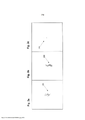
[0037] as Figuras 2a a 2c são ilustrações da iniciação da nuvem de bolhas na água;[0037] Figures 2a to 2c are illustrations of bubble cloud initiation in water;
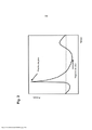
[0038] a Figura 3 ilustra um forma de onda de pressão focal de acordo com uma modalidade;[0038] Figure 3 illustrates a focal pressure waveform according to one embodiment;
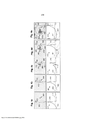
[0039] as Figuras 4a a 4e são desenhos conceituais que ilustram a dispersão de choque;[0039] Figures 4a to 4e are conceptual drawings illustrating shock dispersion;
[0040] as Figuras 5a a 5c ilustram várias modalidades das sequên cias de pulsos que incluem a iniciação e as formas de ondas de pressão de dispersão para a aplicação de energia de ultrassom ao tecido;[0040] Figures 5a to 5c illustrate various embodiments of pulse sequences that include initiation and dispersion pressure waveforms for the application of ultrasound energy to tissue;
[0041] a Figura 6 ilustra um sistema configurado para aplicar as sequências preferidas para tratar o tecido com cavitação.[0041] Figure 6 illustrates a system configured to apply preferred sequences to treat tissue with cavitation.
[0042] Vários princípios de núcleos da cavitação e de formação de nuvem de bolhas que fornecem informações importantes sobre os an-tecedentes para o desenvolvimento da modalidade preferida são di- vulgados no presente documento. Os núcleos de cavitação são bolhas individuais formadas em consequência da aplicação de baixa pressão ao tecido. As nuvens de bolhas podem compreender aglomerados densos de núcleos de cavitação que se formam em ou perto do foco do transdutor. A formação de núcleos de cavitação (nuvens de bolhas) são ambos componentes chaves da terapia de histotripsia.[0042] Several principles of cavitation nuclei and bubble cloud formation that provide important background information for the development of the preferred modality are disclosed in the present document. Cavitation cores are individual bubbles formed as a result of applying low pressure to tissue. Bubble clouds may comprise dense clusters of cavitation nuclei that form at or near the transducer focus. The formation of cavitation nuclei (bubble clouds) are both key components of histotripsy therapy.
[0043] Os núcleos de cavitação podem ser formados no tecido se o tecido for sujeitado a uma pressão negativa de pico (rarefação de pico) que se aproxima de ou excede o nível da pressão necessário para criar pelo menos um único núcleo de cavitação (bolha). Deve ser observado que esse nível é variável e é dependente de múltiplos fatores incluindo as propriedades do tecido (estrutura e composição, teor de gás dissolvido e existência de impurezas), a geometria do transdutor (distância focal e número f), e esquema de arranjo em sequência (PRF; número de ciclos). Foi mostrado que o número dos núcleos de cavitação formados a partir de um pulso acústico está relacionado diretamente à pressão negativa de pico obtida.[0043] Cavitation nuclei can be formed in tissue if the tissue is subjected to a peak negative pressure (peak rarefaction) that approaches or exceeds the pressure level necessary to create at least a single cavitation nucleus (bubble). ). It should be noted that this level is variable and is dependent on multiple factors including tissue properties (structure and composition, dissolved gas content and existence of impurities), transducer geometry (focal distance and f-number), and arrangement scheme. in sequence (PRF; number of cycles). It has been shown that the number of cavitation nuclei formed from an acoustic pulse is directly related to the peak negative pressure obtained.
[0044] Os núcleos de cavitação crescem até um tamanho máximo e então entram em colapso. O curso de tempo de cavitação para o processo de iniciação, crescimento e então colapso das bolhas é dependente do meio (isto é, tipo do tecido). O curso de tempo de cavita- ção para líquidos é mais longo do que em gelatina e no tecido mole. A Tabela 1 compara os tempos de iniciação, crescimento e colapso da cavitação na água versus a gelatina. As Figuras 2a a 2c são ilustrações que mostram um curso de tempo de cavitação típico. A Figura 2a ilustra a iniciação da cavitação 208 em um meio, tal como no tecido, na água, ou em gelatina. A Figura 2b mostra o crescimento da cavita- ção 208 até um tamanho máximo, em que as bolhas de cavitação são agrupadas juntas na zona focal. A Figura 2c ilustra o colapso da cavi- tação 208 onde quase todas as bolhas da cavitação entraram em colapso e desapareceram.
[0045] Enquanto uma forma de onda de som se desloca através do meio, o(s) meio ciclo(s) positivo(s) (compressão) se desloca(m) mais rapidamente do que o(s) meio ciclo(s) negativo(s) (rarefação). Esse efeito faz com que a forma de onda da pressão se torne não linear, criando uma transição aguda entre meios ciclos negativos e positivos da forma de onda da pressão. A amplitude da pressão do meio ciclo positivo aumenta quando a inclinação dessa transição aumenta e é afirmado que a forma de onda de pressão se torna mais não linear ou "chocada". Isso pode ser indicado como uma forma de onda de pressão focal chocada. O nível de não linearidade é dependente da amplitude da pressão do forma de onda de pressão assim como da distância propagada através do meio. A Figura 3 mostra um exemplo de um forma de onda de pressão focal chocada com um meio ciclo positivo e um meio ciclo negativo. Deve ser compreendido que as formas de ondas de pressão focal chocada podem incluir uma pluralidade de meios ciclos positivos e negativos.[0045] As a sound waveform travels through the medium, the positive half cycle(s) (compression) travel faster than the positive half cycle(s) negative(s) (rarefaction). This effect causes the pressure waveform to become nonlinear, creating a sharp transition between negative and positive half cycles of the pressure waveform. The pressure amplitude of the positive half cycle increases as the slope of this transition increases and it is stated that the pressure waveform becomes more nonlinear or "shocked". This can be indicated as a shocked focal pressure waveform. The level of nonlinearity is dependent on the pressure amplitude of the pressure waveform as well as the distance propagated through the medium. Figure 3 shows an example of a shocked focal pressure waveform with a positive half cycle and a negative half cycle. It should be understood that the shocked focal pressure waveforms may include a plurality of positive and negative half-cycles.
[0046] De acordo com a presente invenção, os núcleos de cavita- ção podem ser formados no tecido em consequência da dispersão do choque. A dispersão de choque ocorre quando um meio ciclo de pressão positiva chocada de um forma de onda acústica é refletido, ou disperso, fora de uma bolha(s) pré-existente(s) e o meio ciclo de pressão positiva chocada é invertido consequentemente de maneira tal que combina com meio ciclo de pressão negativa incidente da forma de onda acústica de um modo aditivo. Se esse novo meio ciclo de pressão negativa combinado produzido for grande o bastante (isto é, acima do limite intrínseco para o tecido ou o meio de interesse - maior do que a pressão negativa de pico de 5 MPa, por exemplo), núcleos de cavitação adicionais irão se formar perto de quaisquer núcleos pré- existentes. Esse processo se repete até que o novo meio ciclo de pressão negativa combinado não seja suficiente na pressão para criar novos núcleos de cavitação.[0046] In accordance with the present invention, cavitation cores can be formed in tissue as a result of shock dispersion. Shock scattering occurs when a positive pressure shocked half cycle of an acoustic waveform is reflected, or scattered, off a pre-existing bubble(s) and the shocked positive pressure half cycle is reversed accordingly. such that it combines with the incident negative pressure half cycle of the acoustic waveform in an additive manner. If this new combined negative pressure half-cycle produced is large enough (i.e., above the intrinsic threshold for the tissue or medium of interest - greater than the peak negative pressure of 5 MPa, for example), cavitation nuclei additional ones will form near any pre-existing nuclei. This process repeats until the new combined negative pressure half-cycle is not sufficient in pressure to create new cavitation nuclei.
[0047] As Figuras 4a a 4e são desenhos conceituais que ilustram um método de dispersão de choque de terapia de histotripsia. Os quadros no topo mostram uma bolha pré-existente 408 e um meio ciclo de pressão positiva chocada 410, e os quadros na base mostram a distribuição de pressão de pulso de ultrassom 412 (a linha horizontal 414 indica uma amplitude de pressão igual a zero). A bolha pré-existente 408 pode ser formada com um pulso ou uma sequência de iniciação tal como descrito acima. Uma forma de onda de pressão chocada pode então ser transmitida para a bolha 408 durante um ciclo de vida da bolha de acordo com uma modalidade do método de dispersão de choque.[0047] Figures 4a to 4e are conceptual drawings illustrating a shock scatter method of histotripsy therapy. The top frames show a
[0048] Nas Figuras 4a a 4e, a forma de onda de pressão chocada incidente 412 se propaga da esquerda para a direita rumo à bolha pré- existente 408, tal como indicado pelas setas 416. A forma de onda de pressão chocada incidente pode ser aplicada em e na bolha durante um ciclo de vida da bolha, de modo que a forma de onda de pressão chocada incidente interaja com a bolha. Uma única bolha pré-existente 408 é mostrada na Figura 4a, já tendo sido gerada no tecido tal como descrito acima. A bolha pode se expandir no tamanho, tal como mostrado na Figura 4b, devido ao meio ciclo de pressão negativa inicial da forma de onda de pressão incidente. Na Figura 4c, um meio ciclo de pressão positiva chocada 410 da forma de onda de pressão chocada incidente 412 colide na bolha 408 e o meio ciclo de pressão positiva começa a se dispersar. O meio ciclo de pressão positiva chocada dispersa se inverte e interfere de modo construtivo no meio ciclo de pressão negativa chocada 413 da forma de onda chocada incidente 412 para criar um meio ciclo de pressão negativa de grande amplitude transiente 418 (ilustrado como a linha pontilhada circular 418 nas Figuras 4c a 4e) que produz os núcleos de cavitação adicionais 420 perto ou atrás da bolha 408. O meio ciclo de pressão negativa 418 se propaga da direita para a esquerda, tal como indicado pelas setas 422. Os núcleos de cavitação adicionais 420 se formam na direção oposta da forma de onda de pressão positiva chocada 410, até o meio ciclo de pressão negativa 418 cair abaixo do limite para a formação de núcleos de cavitação, tal como mostrado na Figura 4e. Esse processo pode ser repetido com formas de ondas de pressão chocadas sucessivas transmitidas para e à bolha pré-existente 408 e aos núcleos de cavitação adicionais 420.[0048] In Figures 4a to 4e, the incident
[0049] Os núcleos de cavitação formados por esse método de dis persão de choque tendem a crescer para o transdutor de terapia e a sua extensão depende do número dos ciclos de alta pressão no pulso (forma de onda) e da frequência de repetição de pulso (PRF). A mini- mização do número dos ciclos em uma forma de onda chocada ou a redução da PRF da sequência são maneiras eficazes de reduzir o comprimento da nuvem de bolhas e também de reduzir a intensidade média do tempo e, portanto, a dose térmica.[0049] The cavitation nuclei formed by this method of shock dispersion tend to grow into the therapy transducer and their extent depends on the number of high pressure cycles in the pulse (waveform) and the pulse repetition frequency. (PRF). Minimizing the number of cycles in a shocked waveform or reducing the PRF of the sequence are effective ways to reduce the bubble cloud length and also to reduce the time average intensity and therefore the thermal dose.
[0050] Os componentes chaves de uma sequência preferida de excitação de histotripsia descrita na presente invenção são: 1) um pri- meiro pulso da sequência, indicado como um pulso de iniciação ou forma de onda de pressão de iniciação, configurado para formar pelo menos uma bolha no tecido; 2) um segundo da sequência, indicado como um pulso de dispersão ou forma de onda de pressão de dispersão, configurado para gerar núcleos de cavitação perto de pelo menos uma bolha através de dispersão e choque; e 3) um retardo de tempo específico entre os pulsos de iniciação e de dispersão.[0050] The key components of a preferred histotripsy excitation sequence described in the present invention are: 1) a first pulse of the sequence, denoted as an initiation pulse or initiation pressure waveform, configured to form at least a bubble in the tissue; 2) one second of the sequence, indicated as a scatter pulse or scatter pressure waveform, configured to generate cavitation nuclei near at least one bubble through scattering and shock; and 3) a specific time delay between the initiation and dispersion pulses.
[0051] Os parâmetros chaves para os pulsos são: O pulso de inici ação deve ser configurado para produzir pelo menos uma bolha no tecido de interesse. Isso pode ser conseguido com um pulso de iniciação de histotripsia tradicional, tal como descrito acima, ou com outras técnicas de ultrassom que podem induzir a formação de bolhas no tecido devido à ebulição, tal como HIFU ou histotripsia em ebulição. O pulso de dispersão deve ter uma elevação de pressão pico a pico alta o bastante para a dispersão de choque para a formação de núcleos de cavitação. Em algumas modalidades, o retardo de tempo entre esses pulsos pode variar entre 5 μs e 200 μs. Em uma outra modalidade, o retardo de tempo entre esses pulsos pode variar entre 5 μs e 40 ms. Em uma outra modalidade, o retardo de tempo entre esses pulsos pode variar entre 5 μs e 1 s.[0051] The key parameters for the pulses are: The initiation pulse must be configured to produce at least one bubble in the tissue of interest. This can be accomplished with a traditional histotripsy initiation pulse, as described above, or with other ultrasound techniques that can induce tissue blistering due to boiling, such as HIFU or boiling histotripsy. The scatter pulse must have a high enough peak-to-peak pressure rise for shock scattering to form cavitation nuclei. In some embodiments, the time delay between these pulses can vary between 5 μs and 200 μs. In another embodiment, the time delay between these pulses can vary between 5 µs and 40 ms. In another embodiment, the time delay between these pulses can vary between 5 µs and 1 s.
[0052] Em uma outra modalidade, a amplitude da pressão e/ou o número de ciclos usados no(s) pulso(s) de iniciação podem ser aumentados ou diminuídos. O aumento da amplitude da pressão e/ou do número dos ciclos no pulso de iniciação pode aumentar a probabilidade de criar cavitação no tecido. No entanto, isso também deve aumentar provavelmente a intensidade média do tempo aplicada ao tecido, e a dose térmica aplicada ao tecido, e a extensão da nuvem de bolhas. A diminuição da amplitude da pressão e/ou do número de ciclos de pulso(s) de iniciação vai reduzir a intensidade e a dose térmica da sequência, mas pode limitar a capacidade da sequência de gerar e/ou manter a cavitação.[0052] In another embodiment, the pressure amplitude and/or the number of cycles used in the initiation pulse(s) can be increased or decreased. Increasing the pressure amplitude and/or the number of cycles in the initiation pulse can increase the likelihood of creating tissue cavitation. However, this is also likely to increase the average intensity of time applied to tissue, and the thermal dose applied to tissue, and the extent of the bubble cloud. Decreasing the pressure amplitude and/or the number of cycles of initiation pulse(s) will reduce the intensity and thermal dose of the sequence, but may limit the sequence's ability to generate and/or maintain cavitation.
[0053] Em uma outra modalidade, a amplitude da pressão e/ou o número dos ciclos usados no(s) pulso(s) de dispersão podem ser aumentados ou diminuídos. O aumento da amplitude da pressão e/ou do número de ciclos no(s) pulso(s) de dispersão pode aumentar a probabilidade de criar a cavitação no tecido. No entanto, isso também deve aumentar provavelmente a intensidade média do tempo aplicada ao tecido e a dose térmica aplicada ao tecido e até a extensão da nuvem de bolhas. A diminuição da amplitude da pressão e/ou do número de ciclos de pulso(s) de dispersão vai reduzir a intensidade e a dose térmica da sequência, mas pode limitar a capacidade da sequência de gerar e/ou manter a cavitação.[0053] In another embodiment, the pressure amplitude and/or the number of cycles used in the dispersion pulse(s) can be increased or decreased. Increasing the pressure amplitude and/or the number of cycles in the scatter pulse(s) can increase the likelihood of creating tissue cavitation. However, this is also likely to increase the average intensity of time applied to tissue and the thermal dose applied to tissue and up to the extent of the bubble cloud. Decreasing the pressure amplitude and/or the number of cycles of dispersion pulse(s) will reduce the intensity and thermal dose of the sequence, but may limit the ability of the sequence to generate and/or maintain cavitation.
[0054] A PRF de sequência pode ser tão elevada quanto 5.000 Hz supondo que a intensidade média do tempo e a dose térmica resultante sejam mantidas dentro de limites seguros. A faixa preferida depende dos tecidos que estão sendo tratados. Uma PRF mais elevada é recomendada para os tecidos mais densos e mais fibrosos, e uma baixa PRF é recomendada para os tecidos menos densos e para a preservação de tecidos mais fibrosos e frequentemente vitais. O tratamento seletivo dos tecidos com a histotripsia baseada em sua rigidez pode ser uma consideração de desenho e desempenho provável para o desenvolvimento da sequência.[0054] The sequence PRF can be as high as 5000 Hz assuming the time average intensity and resulting thermal dose are kept within safe limits. The preferred range depends on the fabrics being treated. A higher PRF is recommended for denser and more fibrous tissues, and a lower PRF is recommended for less dense tissues and for the preservation of more fibrous and often vital tissues. Selective tissue treatment with histotripsy based on their stiffness may be a likely design and performance consideration for sequence development.
[0055] Em algumas modalidades, pulsos de dispersão adicionais com amplitude de pressão mais baixa e/ou número de ciclos (em comparação com a amplitude da pressão de pulso de iniciação e/ou o número de ciclos), podem ser aplicados a fim de reduzir a intensidade e a dose térmico da sequência sem reduzir a PRF da sequência.[0055] In some embodiments, additional scatter pulses with lower pressure amplitude and/or number of cycles (compared to the initiation pulse pressure amplitude and/or number of cycles), may be applied in order to reduce the intensity and thermal dose of the sequence without reducing the PRF of the sequence.
[0056] As Figuras 5a a 5c ilustram três modalidades diferentes pa ra a iniciação da histotripsia e sequências de pulsos de dispersão que podem ser usadas para gerar e manter a cavitação no tecido durante um método de dispersão chocada da terapia de histotripsia. Na Figura 5a, um pulso de iniciação 524a que compreende uma forma de onda de pressão configurada para formar pelo menos uma bolha no tecido pode ser transmitido ao tecido. Depois de transcorrido um retardo de tempo específico, um pulso de dispersão 526a pode ser transmitido ao tecido para e em pelo menos uma bolha formada pelo pulso de iniciação 524a. Em algumas modalidades, o retardo de tempo específico entre esses pulsos pode variar entre 5 μs e 200 μs. Em uma outra modalidade, o retardo de tempo entre esses pulsos pode variar entre 5 μs e 40 ms. Em uma outra modalidade, o retardo de tempo entre esses pulsos pode variar entre 5 μs e 1 s. O pulso de dispersão 526a trans-forma-se em uma forma de onda de pressão focal chocada enquanto se desloca através do tecido, e pelo menos um meio ciclo de pressão positiva chocada do pulso de dispersão colide em pelo menos uma bolha e é disperso por pelo menos uma bolha. O meio ciclo de pressão positiva chocada do pulso de dispersão inverte e interfere de modo construtivo no meio ciclo de pressão negativa chocada do pulso de dispersão para criar um meio ciclo de pressão negativa de grande amplitude transiente que produz núcleos de cavitação adicionais atrás de pelo menos uma bolha gerada pelo pulso de iniciação. Esses pares de sequências de pulsos dos pulsos de iniciação e dispersão podem ser repetidos para obter o efeito desejado de ablação no tecido a partir da cavitação resultante, tal como mostrado na Figura 5a (pares de pulsos 524b/526b, 524c/526c, 524d/526d..., 524n/526n). Nesta modalidade, as amplitudes da pressão e/ou o número de ciclos de iniciação e os pulsos de dispersão podem ser os mesmas ou mais ou menos os mesmos.[0056] Figures 5a to 5c illustrate three different modalities for initiating histotripsy and scatter pulse sequences that can be used to generate and maintain tissue cavitation during a shock scatter method of histotripsy therapy. In Figure 5a, an
[0057] A Figura 5b mostra uma outra modalidade, similar à moda lidade da Figura 5a, exceto pelo fato que a amplitude da pressão dos pulsos de dispersão 524a a 524n é menor do que a amplitude de pres- são dos pulsos de iniciação correspondentes. Devido ao princípio de choque, a onda positiva de pico é amplificada em relação à onda negativa de pico e, portanto, a amplitude da pressão usada para criar os pulsos de dispersão pode ser abaixada enquanto ainda é aplicada a pressão negativa necessária com a onda positiva refletida e invertida. Esta modalidade é mais eficiente do que a modalidade da Figura 5a e aplica uma dose menor de energia ao tecido. Em uma outra modalidade, no entanto, a amplitude da pressão dos pulsos de dispersão pode ser maior do que a amplitude da pressão dos pulsos de iniciação correspondentes.[0057] Figure 5b shows another embodiment, similar to the modality of Figure 5a, except that the pressure amplitude of the
[0058] A Figura 5c ilustra uma outra modalidade, a qual é uma va riação da modalidade das Figuras 5a e 5b. Nessa modalidade, o pulso de iniciação 524a é seguido por um pulso de dispersão 526a depois de um retardo de tempo específico, mas em vez de seguir aquele com um outro par de pulsos de iniciação/dispersão tal como na Figura 5a, ao invés de o pulso de dispersão 526a ser seguido por um outro pulso de dispersão 526b depois de um segundo retardo de tempo. Uma pluralidade de pulsos de dispersão pode ser aplicada ao tecido após o retardo de tempo apropriado para manter a eficácia da nuvem de bolhas (por exemplo, os pulsos 526c, 526d) para obter o efeito desejado de ablação no tecido de cavitação resultante. As amplitudes da pressão do pulso de dispersão podem ser menores do que, iguais a ou maiores do que a amplitude da pressão do pulso de iniciação. Em algumas modalidades, o retardo de tempo para as formas de ondas de pressão de dispersão subsequentes pode ser diferente do retardo de tempo usado para a primeira pressão de dispersão. Por exemplo, a primeira forma de onda de pressão de dispersão pode ser aplicada dentro de 5 μs a 200 μs da forma de onda de pressão de iniciação, mas formas de onda de pressão de dispersão subsequentes podem ser aplicadas dentro de 5 μs a 200 μs, de 5μs a 40 ms ou de 5 μs a 1 s. Se a cavita- ção tiver que ser reiniciada no tecido, a sequência pode ser reiniciada com um outro par de pulsos de iniciação/dispersão, tal como mostrado por 524n/526n na Figura 5c. Esta modalidade também usa um pulso de dispersão de amplitude de pressão mais baixa, tal como na modalidade da Figura 5b, mas também usa menos pulsos de iniciação. O resultado desta modalidade é a dose mais baixa de energia aplicada ao tecido entre as modalidades das Figuras 5a a 5c. Esta estratégia tem o potencial de abaixar a dose de maneira significativa (tanto quanto 50%, por exemplo) em comparação com as sequências de histotripsia tradicionais.[0058] Figure 5c illustrates another embodiment, which is a variation of the embodiment of Figures 5a and 5b. In this embodiment, the
[0059] A finalidade do par de iniciação/dispersão é de gerar cavi- tação no tecido com dispersão de choque. Uma vez que a nuvem de bolhas é gerada, e se o foco não for movido, o pulso de iniciação pode não mais ser necessário para manter a eficácia da nuvem de bolhas. Neste caso, o sistema pode ser projetado para criar primeiramente uma nuvem de bolhas com um par de iniciação/dispersão seguir aquele com pulsos de dispersão de amplitude de pressão mais baixa (em relação à amplitude de pressão do pulso de iniciação) até que o foco seja movido. Em cujo ponto o processo é repetido.[0059] The purpose of the initiation/dispersion pair is to generate tissue cavitation with shock dispersion. Once the bubble cloud is generated, and if the focus is not moved, the initiation pulse may no longer be necessary to maintain the bubble cloud's effectiveness. In this case, the system can be designed to first create a cloud of bubbles with an initiation/scattering pair followed by the one with scatter pulses of lower pressure amplitude (relative to the pressure amplitude of the initiation pulse) until the focus be moved. At which point the process is repeated.
[0060] Um sistema e gerador de histotripsia é configurado para gerar formas de onda muito complexas a fim de suportar as sequências de pulso de ultrassom descritas no presente documento. Um diagrama de blocos simplificado do sistema 600 é mostrado na Figura 6. Os componentes principais do sistema são: o Computador/controlador 602, o conversor USB em serial 604, o Microcontrolador 606, FPGA (Arranjo de Porta Programável de Campo) 608, o Controlador de Alta Voltagem e a Fonte de Alimentação 610, o Amplificador 612, e o Transdutor de Terapia 614.[0060] A histotripsy generator and system is configured to generate very complex waveforms in order to support the ultrasound pulse sequences described in this document. A simplified block diagram of the
[0061] Todos os controles para o gerador podem ser estabelecidos ao usar o software "Histotripsy Service Tool" que pode rodar no com- putador/controlador 602 (por exemplo, um PC padrão) e se comunica com o gerador através de uma comunicação serial USB 604.[0061] All controls for the generator can be established using the "Histotripsy Service Tool" software which can run on the 602 computer/controller (e.g. a standard PC) and communicates with the generator via
[0062] O sistema 600 é configurado para receber múltiplos conjun tos de parâmetros de impulsão diferentes e enlaçar os mesmos, o que propicia a capacidade ao usuário de criar uma ampla gama de sequências customizadas onde todos os parâmetros (a PRF, a amplitude de voltagem, o número dos ciclos, o número de pulsos por conjunto, a frequência, os canais de elementos do transdutor habilitados, e o retardo de tempo) podem ser ajustados distintamente para cada pulso gerado. O retardo de tempo entre os pulsos pode ser especificado pela PRF para um conjunto de parâmetros ou ao especificar zero como o número de ciclos por pulso.[0062] The 600 system is configured to receive multiple sets of different impulse parameters and link them together, which provides the ability for the user to create a wide range of custom sequences where all parameters (PRF, voltage amplitude , number of cycles, number of pulses per set, frequency, transducer element channels enabled, and time delay) can be set separately for each generated pulse. The time delay between pulses can be specified by PRF for a parameter set or by specifying zero as the number of cycles per pulse.
[0063] Para a regulação da amplitude da voltagem total, o nível de alta voltagem é alterado de modo correspondente através do micro- controlador 606 e do controlador HV 610. Esse método não pode ser usado para mudanças dinâmicas da amplitude de voltagem entre dois pulsos, uma vez que irá levar muito tempo que para todos os capacito- res na linha de alta tensão sejam descarregados. Para mudanças dinâmicas da amplitude de voltagem entre pulsos, a PWM (modulação em largura de pulso) é usada em FPGA 608 onde o ciclo de trabalho do pulso é modulado a fim de produzir a voltagem de pulso desejada e a amplitude de pressão resultante.[0063] For full voltage amplitude regulation, the high voltage level is correspondingly changed via the 606 microcontroller and the 610 HV controller. This method cannot be used for dynamic voltage amplitude changes between two pulses. , as it will take a long time for all the capacitors in the high voltage line to discharge. For dynamic changes in voltage amplitude between pulses, PWM (Pulse Width Modulation) is used in
[0064] A ferramenta de trabalho de histotripsia é um aplicativo que pode ser rodado em qualquer PC e é usada para controlar o sistema. A Ferramenta de Trabalho de Histotripsia pode iniciar/terminar a tera- pia, ajustar e ler o nível de alta voltagem, os parâmetros da terapia (a PRF, o número de ciclos, a razão de trabalho, o canal habilitado e o retardo, etc.), e ajustar e ler outros itens relacionados a serviço e manutenção.[0064] Histotripsy Job Tool is an application that can be run on any PC and is used to control the system. The Histotripsy Job Tool can start/stop therapy, set and read the high voltage level, therapy parameters (PRF, number of cycles, duty rate, enabled channel and delay, etc. .), and adjust and read other service and maintenance related items.
[0065] O conversor USB em serial 604 converte a combinação USB em serial a fim de se comunicar como microcontrolador 606.[0065] USB to
[0066] O microcontrolador 606 se comunica com o computa- dor/controlador 602 (Ferramenta de Trabalho de Histotripsia) para ajustar/ler os parâmetros de trabalho, iniciar/terminar a terapia, etc. Ele pode usar a memória flash interna para armazenar todos os parâmetros. O microcontrolador comunica a FPGA 608 todos os parâmetros de impulsão que são necessários para gerar uma pulsação complexa. Ele também se comunica ao usar a comunicação serial com o controlador de alta voltagem e a fonte de alimentação 610 onde pode ajus- tar/ler o nível apropriado da voltagem de impulsão.[0066]
[0067] O FPGA 608 recebe a informação do microcontrolador 606 e gera a sequência de pulsação complexa que é requerida para impelir o amplificador 612. O FPGA pode rodar no relógio de 100 MHz uma vez que a velocidade de pulsação é crítica para ser cronometrada em incrementos de 10 ns.[0067]
[0068] O Controlador de Alta Voltagem e a Fonte de Alimentação 610 recebem os comandos do microcontrolador 606 a respeito do nível da voltagem C.C. que precisa ser fornecida aos circuitos do amplificador a fim de ter um nível de amplitude de voltagem adequado na saída do amplificador.[0068] The High Voltage Controller and
[0069] O Amplificador 612 recebe os pulsos gerados pelo FPGA e é alimentado com alta voltagem do Controlador de Alta Voltagem e a Fonte de Alimentação. Gera os pulsos de amplitude de alta voltagem que são alimentados ao transdutor de terapia 614 através dos componentes de rede de combinação que combinam adequadamente a im- pedância do transdutor de terapia com a impedância do amplificador. É necessário usar um grande número de capacitores que podem armazenar bastante energia para suportar a demanda de corrente de pico durante a geração de pulsos de amplitude de alta voltagem.[0069] The 612 Amplifier receives the pulses generated by the FPGA and is supplied with high voltage from the High Voltage Controller and the Power Supply. It generates the high-voltage amplitude pulses that are fed to the 614 therapy transducer through combination network components that properly match the impedance of the therapy transducer to the impedance of the amplifier. It is necessary to use a large number of capacitors that can store enough energy to support the peak current demand during the generation of high voltage amplitude pulses.
[0070] As estruturas e o código de dados descritos nesta descri ção detalhada são armazenados tipicamente em um meio de armazenamento que pode ser lido por computador, o qual pode ser qualquer dispositivo ou meio que possa armazenar o código e/ou os dados para o uso por um sistema computadorizado. O meio de armazenamento que pode ser lido por computador inclui, mas sem ficar a eles limitado, memória volátil, memória não volátil, dispositivos de armazenamento magnéticos e ópticos tais como drives de disco, fita magnética, CDs (discos compactos), DVDs (discos versáteis digitais ou discos de vídeo digitais), ou outros meios com capacidade de armazenar meios que podem ser lidos por computador atualmente conhecidos ou desenvolvidos mais tarde.[0070] The data structures and code described in this detailed description are typically stored on a computer-readable storage medium, which can be any device or medium that can store code and/or data for the use by a computer system. Computer readable storage media include, but are not limited to, volatile memory, non-volatile memory, magnetic and optical storage devices such as disk drives, magnetic tape, CDs (compact discs), DVDs (discs). digital versatile discs or digital video discs), or other media capable of storing computer readable media now known or later developed.
[0071] Os métodos e os processos descritos na seção detalhada da descrição podem ser incorporados como código e/ou dados, os quais podem ser armazenados em um meio de armazenamento que pode ser lido por computador tal como descrito acima. Quando um sistema computadorizado lê e executa o código e/ou os dados armazenados no meio de armazenamento que pode ser lido por computador, o sistema computadorizado executa os métodos e os processos incorporados como estruturas de dados e código e armazenados dentro do meio de armazenamento que pode ser lido por computador.[0071] The methods and processes described in the detailed section of the description may be incorporated as code and/or data, which may be stored on a computer readable storage medium as described above. When a computer system reads and executes code and/or data stored on the computer-readable storage medium, the computer system executes the methods and processes embedded as data structures and code and stored within the storage medium that can be read by computer.
[0072] Além disso, os métodos e os processos descritos acima podem ser incluídos nos módulos de hardware. Por exemplo, os módulos de hardware podem incluir, mas sem ficar a eles limitados, chips de circuitos integrados específicos de aplicativos (ASIC), arranjos de porta programáveis em campo (FPGAs), e outros dispositivos de lógica programável atualmente conhecidos ou desenvolvidos mais tarde. Quando os módulos de hardware são ativados, os módulos de hardware executam os métodos e os processos incluídos dentro dos módulos de hardware.[0072] In addition, the methods and processes described above can be included in the hardware modules. For example, hardware modules may include, but are not limited to, application-specific integrated circuit (ASIC) chips, field-programmable gate arrays (FPGAs), and other programmable logic devices now known or later developed. . When hardware modules are activated, the hardware modules run the methods and processes included within the hardware modules.
[0073] Os exemplos e as ilustrações incluídos no presente docu mento mostram, a título de ilustração e não de limitação, as modalidades específicas em que o objeto pode ser praticado. Tal como mencionado, outras modalidades podem ser utilizadas e derivadas dos mesmos, de maneira tal que substituições e mudanças estruturais e lógicas podem ser feitas sem desviar do âmbito da presente invenção. Tais modalidades do objeto da invenção podem ser indicadas no presente documento individual ou coletivamente pelo termo "invenção" meramente para fins de conveniência e sem pretender limitar voluntariamente o âmbito do presente pedido de patente a qualquer invenção simples ou conceito inventivo, se houver mais de um, de fato, for divulgado. Desse modo, embora as modalidades específicas sejam ilustradas e descritas no presente documento, qualquer arranjo calculado para atingir a mesma finalidade pode ser substituído para as modalidade específicas mostradas. A presente invenção se presta a cobrir toda e qualquer adaptação ou variação de várias modalidades. As combinações das modalidades acima, e outras modalidades não especificamente descritas no presente documento, serão aparentes aos elementos versados na técnica com a revisão da descrição acima.[0073] The examples and illustrations included in this document show, by way of illustration and not limitation, the specific modalities in which the object can be practiced. As mentioned, other embodiments can be used and derived therefrom, such that structural and logical substitutions and changes can be made without departing from the scope of the present invention. Such embodiments of the subject matter of the invention may be indicated herein individually or collectively by the term "invention" merely for convenience purposes and without intending to voluntarily limit the scope of the present patent application to any single invention or inventive concept, if there is more than one , in fact, is disclosed. Thus, while specific embodiments are illustrated and described herein, any arrangement calculated to achieve the same purpose may be substituted for the specific embodiments shown. The present invention is intended to cover any and all adaptations or variations of various embodiments. Combinations of the above embodiments, and other embodiments not specifically described herein, will be apparent to those skilled in the art upon review of the above description.
Claims (4)
Applications Claiming Priority (3)
| Application Number | Priority Date | Filing Date | Title |
|---|---|---|---|
| US201361842820P | 2013-07-03 | 2013-07-03 | |
| US61/842,820 | 2013-07-03 | ||
| PCT/US2014/045431 WO2015003142A1 (en) | 2013-07-03 | 2014-07-03 | Histotripsy excitation sequences optimized for bubble cloud formation using shock scattering |
Publications (2)
| Publication Number | Publication Date |
|---|---|
| BR112015032926A2 BR112015032926A2 (en) | 2017-07-25 |
| BR112015032926B1 true BR112015032926B1 (en) | 2022-04-05 |
Family
ID=52133288
Family Applications (1)
| Application Number | Title | Priority Date | Filing Date |
|---|---|---|---|
| BR112015032926-8A BR112015032926B1 (en) | 2013-07-03 | 2014-07-03 | ULTRASOUND THERAPY SYSTEM |
Country Status (9)
| Country | Link |
|---|---|
| US (2) | US10293187B2 (en) |
| EP (2) | EP3016594B1 (en) |
| JP (3) | JP6600304B2 (en) |
| CN (1) | CN105530869B (en) |
| BR (1) | BR112015032926B1 (en) |
| ES (1) | ES2941665T3 (en) |
| IL (1) | IL243001A0 (en) |
| MX (1) | MX369950B (en) |
| WO (1) | WO2015003142A1 (en) |
Families Citing this family (11)
| Publication number | Priority date | Publication date | Assignee | Title |
|---|---|---|---|---|
| US10219815B2 (en) | 2005-09-22 | 2019-03-05 | The Regents Of The University Of Michigan | Histotripsy for thrombolysis |
| CA2770452C (en) | 2009-08-17 | 2017-09-19 | Histosonics, Inc. | Disposable acoustic coupling medium container |
| US9144694B2 (en) | 2011-08-10 | 2015-09-29 | The Regents Of The University Of Michigan | Lesion generation through bone using histotripsy therapy without aberration correction |
| EP2903688A4 (en) | 2012-10-05 | 2016-06-15 | Univ Michigan | Bubble-induced color doppler feedback during histotripsy |
| US11432900B2 (en) | 2013-07-03 | 2022-09-06 | Histosonics, Inc. | Articulating arm limiter for cavitational ultrasound therapy system |
| US10780298B2 (en) | 2013-08-22 | 2020-09-22 | The Regents Of The University Of Michigan | Histotripsy using very short monopolar ultrasound pulses |
| ES2948135T3 (en) | 2015-06-24 | 2023-08-31 | Univ Michigan Regents | Histotripsy therapy systems for the treatment of brain tissue |
| GB201617255D0 (en) * | 2016-10-11 | 2016-11-23 | Oxford University Innovation Limited | Modular ultrasound apparatus and methods |
| CN113286552A (en) | 2018-11-28 | 2021-08-20 | 希斯托索尼克斯公司 | Histotripsy system and method |
| US11497465B2 (en) | 2019-10-25 | 2022-11-15 | Bard Peripheral Vascular, Inc. | Method for treatment of a vascular lesion |
| CA3169465A1 (en) | 2020-01-28 | 2021-08-05 | The Regents Of The University Of Michigan | Systems and methods for histotripsy immunosensitization |
Family Cites Families (323)
| Publication number | Priority date | Publication date | Assignee | Title |
|---|---|---|---|---|
| US3243497A (en) | 1964-12-11 | 1966-03-29 | Dynapower Systems Corp Of Cali | Universal support for electrotherapeutic treatment head |
| US3679021A (en) | 1970-03-25 | 1972-07-25 | Eg & G Inc | Acoustic pulse generating system |
| US4016749A (en) | 1973-07-05 | 1977-04-12 | Wachter William J | Method and apparatus for inspection of nuclear fuel rods |
| FR2355288A2 (en) | 1974-11-28 | 1978-01-13 | Anvar | IMPROVEMENTS IN ULTRA-SOUND SURVEYING METHODS AND DEVICES |
| US4024501A (en) | 1975-09-03 | 1977-05-17 | Standard Oil Company | Line driver system |
| US4051394A (en) | 1976-03-15 | 1977-09-27 | The Boeing Company | Zero crossing ac relay control circuit |
| US4277367A (en) | 1978-10-23 | 1981-07-07 | Wisconsin Alumni Research Foundation | Phantom material and method |
| GB2048477A (en) | 1979-03-20 | 1980-12-10 | Gen Electric Co Ltd | Ultrasonic imaging system |
| US4406153A (en) | 1979-05-04 | 1983-09-27 | Acoustic Standards Corporation | Ultrasonic beam characterization device |
| US4269174A (en) | 1979-08-06 | 1981-05-26 | Medical Dynamics, Inc. | Transcutaneous vasectomy apparatus and method |
| FR2472753A1 (en) | 1979-12-31 | 1981-07-03 | Anvar | IMPROVEMENTS IN ULTRA-SOUND SURVEYING DEVICES |
| US4305296B2 (en) | 1980-02-08 | 1989-05-09 | Ultrasonic imaging method and apparatus with electronic beam focusing and scanning | |
| JPS5711648A (en) | 1980-06-27 | 1982-01-21 | Matsushita Electric Ind Co Ltd | Ultrasonic probe |
| US4453408A (en) | 1981-03-09 | 1984-06-12 | William Clayman | Device for testing ultrasonic beam profiles |
| JPS5826238A (en) | 1981-08-08 | 1983-02-16 | Fujitsu Ltd | Pressure measurement system by ultrasonic wave |
| US4622972A (en) | 1981-10-05 | 1986-11-18 | Varian Associates, Inc. | Ultrasound hyperthermia applicator with variable coherence by multi-spiral focusing |
| DE3220751A1 (en) | 1982-06-02 | 1983-12-08 | Jörg Dr. 8022 Grünwald Schüller | Device for crushing concrements, especially renal calculi, in living human or animal bodies |
| US4550606A (en) | 1982-09-28 | 1985-11-05 | Cornell Research Foundation, Inc. | Ultrasonic transducer array with controlled excitation pattern |
| JPS6080779A (en) | 1983-10-07 | 1985-05-08 | Matsushita Electric Ind Co Ltd | Magnetic field sensor |
| US5158070A (en) | 1983-12-14 | 1992-10-27 | Edap International, S.A. | Method for the localized destruction of soft structures using negative pressure elastic waves |
| US5143074A (en) | 1983-12-14 | 1992-09-01 | Edap International | Ultrasonic treatment device using a focussing and oscillating piezoelectric element |
| US5143073A (en) | 1983-12-14 | 1992-09-01 | Edap International, S.A. | Wave apparatus system |
| USRE33590E (en) | 1983-12-14 | 1991-05-21 | Edap International, S.A. | Method for examining, localizing and treating with ultrasound |
| US5150711A (en) | 1983-12-14 | 1992-09-29 | Edap International, S.A. | Ultra-high-speed extracorporeal ultrasound hyperthermia treatment device |
| US4549533A (en) | 1984-01-30 | 1985-10-29 | University Of Illinois | Apparatus and method for generating and directing ultrasound |
| US4641378A (en) | 1984-06-06 | 1987-02-03 | Raycom Systems, Inc. | Fiber optic communication module |
| DE3425705A1 (en) | 1984-07-12 | 1986-01-16 | Siemens AG, 1000 Berlin und 8000 München | PHASED ARRAY DEVICE |
| DE3427001C1 (en) | 1984-07-21 | 1986-02-06 | Dornier System Gmbh, 7990 Friedrichshafen | Locating and positioning device |
| US4575330A (en) | 1984-08-08 | 1986-03-11 | Uvp, Inc. | Apparatus for production of three-dimensional objects by stereolithography |
| US4625731A (en) | 1984-10-10 | 1986-12-02 | Picker International, Inc. | Ultrasonic image display mounting |
| US5431621A (en) | 1984-11-26 | 1995-07-11 | Edap International | Process and device of an anatomic anomaly by means of elastic waves, with tracking of the target and automatic triggering of the shootings |
| JPS61196718A (en) | 1985-02-22 | 1986-08-30 | 株式会社日立製作所 | Ground-fault protector |
| US4689986A (en) | 1985-03-13 | 1987-09-01 | The University Of Michigan | Variable frequency gas-bubble-manipulating apparatus and method |
| JPS61209643A (en) | 1985-03-15 | 1986-09-17 | 株式会社東芝 | Ultrasonic diagnostic and medical treatment apparatus |
| US4865042A (en) | 1985-08-16 | 1989-09-12 | Hitachi, Ltd. | Ultrasonic irradiation system |
| DE3580848D1 (en) | 1985-09-24 | 1991-01-17 | Hewlett Packard Gmbh | SWITCHING MATRIX. |
| DE3544628A1 (en) | 1985-12-17 | 1987-06-19 | Eisenmenger Wolfgang | DEVICE FOR MECHANICALLY ACOUSTIC CONNECTION OF PRESSURE SHAFTS, ESPECIALLY OF FOCUSED SHOCK WAVES TO THE BODY OF LIVING BEINGS |
| DE3607949A1 (en) | 1986-03-11 | 1987-09-17 | Wolf Gmbh Richard | METHOD FOR DETECTING POSSIBLE TISSUE DAMAGE IN THE MEDICAL APPLICATION OF HIGH-ENERGY SOUND |
| US4791915A (en) | 1986-09-29 | 1988-12-20 | Dynawave Corporation | Ultrasound therapy device |
| US4984575A (en) | 1987-04-16 | 1991-01-15 | Olympus Optical Co., Ltd. | Therapeutical apparatus of extracorporeal type |
| FR2614722B1 (en) | 1987-04-28 | 1992-04-17 | Dory Jacques | ACOUSTIC FILTER FOR SUPPRESSING OR MITIGATING NEGATIVE ALTERNATIONS OF AN ELASTIC WAVE AND ELASTIC WAVE GENERATOR COMPRISING SUCH A FILTER |
| FR2614747B1 (en) | 1987-04-28 | 1989-07-28 | Dory Jacques | ELASTIC PULSE GENERATOR HAVING A PREDETERMINED WAVEFORM AND ITS APPLICATION TO TREATMENT OR MEDICAL DIAGNOSIS |
| FR2619448B1 (en) | 1987-08-14 | 1990-01-19 | Edap Int | METHOD AND DEVICE FOR TISSUE CHARACTERIZATION BY REFLECTION OF ULTRASONIC PULSES WITH BROADBAND FREQUENCIES, TRANSPOSITION OF THE ECHO FREQUENCY SPECTRUM IN AN AUDIBLE RANGE AND LISTENING DIAGNOSIS |
| US4973980A (en) | 1987-09-11 | 1990-11-27 | Dataproducts Corporation | Acoustic microstreaming in an ink jet apparatus |
| DE3732131A1 (en) | 1987-09-24 | 1989-04-06 | Wolf Gmbh Richard | FOCUSING ULTRASONIC transducer |
| DE3741201A1 (en) | 1987-12-02 | 1989-06-15 | Schering Ag | ULTRASONIC PROCESS AND METHOD FOR IMPLEMENTING IT |
| US4989143A (en) | 1987-12-11 | 1991-01-29 | General Electric Company | Adaptive coherent energy beam formation using iterative phase conjugation |
| US5163421A (en) | 1988-01-22 | 1992-11-17 | Angiosonics, Inc. | In vivo ultrasonic system with angioplasty and ultrasonic contrast imaging |
| US4957099A (en) | 1988-02-10 | 1990-09-18 | Siemens Aktiengesellschaft | Shock wave source for extracorporeal lithotripsy |
| US5209221A (en) | 1988-03-01 | 1993-05-11 | Richard Wolf Gmbh | Ultrasonic treatment of pathological tissue |
| DE3808783A1 (en) | 1988-03-16 | 1989-10-05 | Dornier Medizintechnik | STONE CRUSHING BY COMBINED TREATMENT |
| DE3817094A1 (en) | 1988-04-18 | 1989-11-30 | Schubert Werner | Coupling and adhesive device for shock wave treatment units |
| US4938217A (en) | 1988-06-21 | 1990-07-03 | Massachusetts Institute Of Technology | Electronically-controlled variable focus ultrasound hyperthermia system |
| US5158071A (en) | 1988-07-01 | 1992-10-27 | Hitachi, Ltd. | Ultrasonic apparatus for therapeutical use |
| EP0548048B1 (en) | 1988-10-26 | 1996-02-14 | Kabushiki Kaisha Toshiba | Shock wave treatment apparatus |
| FR2642640B1 (en) | 1989-02-08 | 1991-05-10 | Centre Nat Rech Scient | METHOD AND DEVICE FOR FOCUSING ULTRASOUND IN TISSUES |
| JPH02217000A (en) | 1989-02-16 | 1990-08-29 | Hitachi Ltd | Ultrasonic wave probe |
| JP2694992B2 (en) | 1989-02-17 | 1997-12-24 | 株式会社東芝 | Stone crushing equipment |
| FR2643252B1 (en) | 1989-02-21 | 1991-06-07 | Technomed Int Sa | APPARATUS FOR THE SELECTIVE DESTRUCTION OF CELLS INCLUDING SOFT TISSUES AND BONES WITHIN THE BODY OF A LIVING BODY BY IMPLOSION OF GAS BUBBLES |
| US5435311A (en) | 1989-06-27 | 1995-07-25 | Hitachi, Ltd. | Ultrasound therapeutic system |
| US5065761A (en) | 1989-07-12 | 1991-11-19 | Diasonics, Inc. | Lithotripsy system |
| US5014686A (en) | 1989-08-31 | 1991-05-14 | International Sonic Technologies | Phantom kidney stone system |
| US6088613A (en) | 1989-12-22 | 2000-07-11 | Imarx Pharmaceutical Corp. | Method of magnetic resonance focused surgical and therapeutic ultrasound |
| US5542935A (en) | 1989-12-22 | 1996-08-06 | Imarx Pharmaceutical Corp. | Therapeutic delivery systems related applications |
| US5580575A (en) | 1989-12-22 | 1996-12-03 | Imarx Pharmaceutical Corp. | Therapeutic drug delivery systems |
| US5065751A (en) | 1990-01-03 | 1991-11-19 | Wolf Gerald L | Method and apparatus for reversibly occluding a biological tube |
| US5165412A (en) | 1990-03-05 | 1992-11-24 | Kabushiki Kaisha Toshiba | Shock wave medical treatment apparatus with exchangeable imaging ultrasonic wave probe |
| US5091893A (en) | 1990-04-05 | 1992-02-25 | General Electric Company | Ultrasonic array with a high density of electrical connections |
| DE4012760A1 (en) | 1990-04-21 | 1992-05-07 | G M T I Ges Fuer Medizintechni | Ultrasonic Doppler method for gallstone lithography - uses analysis of Doppler frequency shift to detect velocity and calculating size of tracked particles |
| US5215680A (en) | 1990-07-10 | 1993-06-01 | Cavitation-Control Technology, Inc. | Method for the production of medical-grade lipid-coated microbubbles, paramagnetic labeling of such microbubbles and therapeutic uses of microbubbles |
| US6344489B1 (en) | 1991-02-14 | 2002-02-05 | Wayne State University | Stabilized gas-enriched and gas-supersaturated liquids |
| US5316000A (en) | 1991-03-05 | 1994-05-31 | Technomed International (Societe Anonyme) | Use of at least one composite piezoelectric transducer in the manufacture of an ultrasonic therapy apparatus for applying therapy, in a body zone, in particular to concretions, to tissue, or to bones, of a living being and method of ultrasonic therapy |
| US5524620A (en) | 1991-11-12 | 1996-06-11 | November Technologies Ltd. | Ablation of blood thrombi by means of acoustic energy |
| ATE144124T1 (en) | 1991-12-20 | 1996-11-15 | Technomed Medical Systems | DEVICE FOR ULTRASONIC THERAPY EMITTING SOUND WAVES, THERMAL EFFECTS AND CAVITATION EFFECTS |
| US6436078B1 (en) | 1994-12-06 | 2002-08-20 | Pal Svedman | Transdermal perfusion of fluids |
| FR2685872A1 (en) | 1992-01-07 | 1993-07-09 | Edap Int | APPARATUS OF EXTRACORPOREAL ULTRASONIC HYPERTHERMIA WITH VERY HIGH POWER AND ITS OPERATING METHOD. |
| DE4207463C2 (en) | 1992-03-10 | 1996-03-28 | Siemens Ag | Arrangement for the therapy of tissue with ultrasound |
| WO1993019705A1 (en) | 1992-03-31 | 1993-10-14 | Massachusetts Institute Of Technology | Apparatus and method for acoustic heat generation and hyperthermia |
| US5230340A (en) | 1992-04-13 | 1993-07-27 | General Electric Company | Ultrasound imaging system with improved dynamic focusing |
| US5295484A (en) | 1992-05-19 | 1994-03-22 | Arizona Board Of Regents For And On Behalf Of The University Of Arizona | Apparatus and method for intra-cardiac ablation of arrhythmias |
| US5362309A (en) | 1992-09-14 | 1994-11-08 | Coraje, Inc. | Apparatus and method for enhanced intravascular phonophoresis including dissolution of intravascular blockage and concomitant inhibition of restenosis |
| WO1994006380A1 (en) | 1992-09-16 | 1994-03-31 | Hitachi, Ltd. | Ultrasonic irradiation apparatus and processor using the same |
| DE4238645C1 (en) | 1992-11-16 | 1994-05-05 | Siemens Ag | Therapeutic ultrasonic applicator for urogenital area - has ultrasonic waves focussed onto working zone defined by envelope curve with two perpendicular main axes |
| US5573497A (en) | 1994-11-30 | 1996-11-12 | Technomed Medical Systems And Institut National | High-intensity ultrasound therapy method and apparatus with controlled cavitation effect and reduced side lobes |
| US5469852A (en) | 1993-03-12 | 1995-11-28 | Kabushiki Kaisha Toshiba | Ultrasound diagnosis apparatus and probe therefor |
| DE4310924C2 (en) | 1993-04-02 | 1995-01-26 | Siemens Ag | Therapy device for the treatment of pathological tissue with ultrasound waves and a catheter |
| DE4403134A1 (en) | 1993-05-14 | 1995-08-03 | Laser Medizin Zentrum Ggmbh Be | Combination device for thermal obliteration of biological tissue |
| US6056738A (en) | 1997-01-31 | 2000-05-02 | Transmedica International, Inc. | Interstitial fluid monitoring |
| DE4405504B4 (en) | 1994-02-21 | 2008-10-16 | Siemens Ag | Method and apparatus for imaging an object with a 2-D ultrasound array |
| US5509896A (en) | 1994-09-09 | 1996-04-23 | Coraje, Inc. | Enhancement of thrombolysis with external ultrasound |
| JPH0884740A (en) | 1994-09-16 | 1996-04-02 | Toshiba Corp | Treatment apparatus |
| US5694936A (en) | 1994-09-17 | 1997-12-09 | Kabushiki Kaisha Toshiba | Ultrasonic apparatus for thermotherapy with variable frequency for suppressing cavitation |
| JP3754113B2 (en) | 1994-09-17 | 2006-03-08 | 株式会社東芝 | Ultrasonic therapy device |
| US5540909A (en) | 1994-09-28 | 1996-07-30 | Alliance Pharmaceutical Corp. | Harmonic ultrasound imaging with microbubbles |
| EP0709673A1 (en) | 1994-10-25 | 1996-05-01 | Laboratoires D'electronique Philips | Apparatus for non-destructive testing of hollow tubular articles with ultrasound |
| US5520188A (en) | 1994-11-02 | 1996-05-28 | Focus Surgery Inc. | Annular array transducer |
| WO1996022116A1 (en) | 1995-01-20 | 1996-07-25 | Medela, Inc. | Device and method for supporting a breast shield and related pump equipment |
| DE19507305A1 (en) | 1995-03-02 | 1996-09-05 | Delma Elektro Med App | Operating light with main lamp and spare lamp |
| US5678554A (en) | 1996-07-02 | 1997-10-21 | Acuson Corporation | Ultrasound transducer for multiple focusing and method for manufacture thereof |
| US6176842B1 (en) | 1995-03-08 | 2001-01-23 | Ekos Corporation | Ultrasound assembly for use with light activated drugs |
| US5873902A (en) | 1995-03-31 | 1999-02-23 | Focus Surgery, Inc. | Ultrasound intensity determining method and apparatus |
| US5617862A (en) | 1995-05-02 | 1997-04-08 | Acuson Corporation | Method and apparatus for beamformer system with variable aperture |
| US5558092A (en) | 1995-06-06 | 1996-09-24 | Imarx Pharmaceutical Corp. | Methods and apparatus for performing diagnostic and therapeutic ultrasound simultaneously |
| US6521211B1 (en) | 1995-06-07 | 2003-02-18 | Bristol-Myers Squibb Medical Imaging, Inc. | Methods of imaging and treatment with targeted compositions |
| US5566675A (en) | 1995-06-30 | 1996-10-22 | Siemens Medical Systems, Inc. | Beamformer for phase aberration correction |
| DE69520670T2 (en) | 1995-07-27 | 2001-09-13 | Agilent Technologies Deutschla | Patient monitoring module |
| US5582578A (en) | 1995-08-01 | 1996-12-10 | Duke University | Method for the comminution of concretions |
| JPH0955571A (en) | 1995-08-11 | 1997-02-25 | Hewlett Packard Japan Ltd | Electronic circuit board with high insulation section and its production |
| US5648098A (en) | 1995-10-17 | 1997-07-15 | The Board Of Regents Of The University Of Nebraska | Thrombolytic agents and methods of treatment for thrombosis |
| US5590657A (en) | 1995-11-06 | 1997-01-07 | The Regents Of The University Of Michigan | Phased array ultrasound system and method for cardiac ablation |
| US6321109B2 (en) | 1996-02-15 | 2001-11-20 | Biosense, Inc. | Catheter based surgery |
| US5676692A (en) | 1996-03-28 | 1997-10-14 | Indianapolis Center For Advanced Research, Inc. | Focussed ultrasound tissue treatment method |
| CH691345A5 (en) | 1996-04-18 | 2001-07-13 | Siemens Ag | Therapy device by a simple adjustment of a desired distance from a reference point. |
| US20020045890A1 (en) | 1996-04-24 | 2002-04-18 | The Regents Of The University O F California | Opto-acoustic thrombolysis |
| US6022309A (en) | 1996-04-24 | 2000-02-08 | The Regents Of The University Of California | Opto-acoustic thrombolysis |
| US5724972A (en) | 1996-05-02 | 1998-03-10 | Acuson Corporation | Method and apparatus for distributed focus control with slope tracking |
| US5717657A (en) | 1996-06-24 | 1998-02-10 | The United States Of America As Represented By The Secretary Of The Navy | Acoustical cavitation suppressor for flow fields |
| US5849727A (en) | 1996-06-28 | 1998-12-15 | Board Of Regents Of The University Of Nebraska | Compositions and methods for altering the biodistribution of biological agents |
| US5836896A (en) | 1996-08-19 | 1998-11-17 | Angiosonics | Method of inhibiting restenosis by applying ultrasonic energy |
| US5753929A (en) | 1996-08-28 | 1998-05-19 | Motorola, Inc. | Multi-directional optocoupler and method of manufacture |
| DE19635593C1 (en) | 1996-09-02 | 1998-04-23 | Siemens Ag | Ultrasound transducer for diagnostic and therapeutic use |
| CA2213948C (en) | 1996-09-19 | 2006-06-06 | United States Surgical Corporation | Ultrasonic dissector |
| US6036667A (en) | 1996-10-04 | 2000-03-14 | United States Surgical Corporation | Ultrasonic dissection and coagulation system |
| US5769790A (en) | 1996-10-25 | 1998-06-23 | General Electric Company | Focused ultrasound surgery system guided by ultrasound imaging |
| US5827204A (en) | 1996-11-26 | 1998-10-27 | Grandia; Willem | Medical noninvasive operations using focused modulated high power ultrasound |
| US5797848A (en) | 1997-01-31 | 1998-08-25 | Acuson Corporation | Ultrasonic transducer assembly with improved electrical interface |
| WO1998048711A1 (en) | 1997-05-01 | 1998-11-05 | Ekos Corporation | Ultrasound catheter |
| US5879314A (en) | 1997-06-30 | 1999-03-09 | Cybersonics, Inc. | Transducer assembly and method for coupling ultrasonic energy to a body for thrombolysis of vascular thrombi |
| US6093883A (en) | 1997-07-15 | 2000-07-25 | Focus Surgery, Inc. | Ultrasound intensity determining method and apparatus |
| US5944666A (en) | 1997-08-21 | 1999-08-31 | Acuson Corporation | Ultrasonic method for imaging blood flow including disruption or activation of contrast agent |
| US6128958A (en) | 1997-09-11 | 2000-10-10 | The Regents Of The University Of Michigan | Phased array system architecture |
| US6113558A (en) | 1997-09-29 | 2000-09-05 | Angiosonics Inc. | Pulsed mode lysis method |
| AU1377699A (en) | 1997-11-03 | 1999-05-24 | Barzell Whitmore Maroon Bells, Inc. | Ultrasound interface control system |
| DE19800416C2 (en) | 1998-01-08 | 2002-09-19 | Storz Karl Gmbh & Co Kg | Device for the treatment of body tissue, in particular soft tissue close to the surface, by means of ultrasound |
| US7273458B2 (en) | 1998-01-12 | 2007-09-25 | Georgia Tech Research Corporation | Method of applying acoustic energy effective to alter transport or cell viability |
| US6896659B2 (en) | 1998-02-06 | 2005-05-24 | Point Biomedical Corporation | Method for ultrasound triggered drug delivery using hollow microbubbles with controlled fragility |
| US6511444B2 (en) | 1998-02-17 | 2003-01-28 | Brigham And Women's Hospital | Transmyocardial revascularization using ultrasound |
| US6659105B2 (en) | 1998-02-26 | 2003-12-09 | Senorx, Inc. | Tissue specimen isolating and damaging device and method |
| US6165144A (en) | 1998-03-17 | 2000-12-26 | Exogen, Inc. | Apparatus and method for mounting an ultrasound transducer |
| US6685640B1 (en) | 1998-03-30 | 2004-02-03 | Focus Surgery, Inc. | Ablation system |
| FR2778573B1 (en) | 1998-05-13 | 2000-09-22 | Technomed Medical Systems | FREQUENCY ADJUSTMENT IN A HIGH INTENSITY FOCUSED ULTRASOUND TREATMENT APPARATUS |
| JP4095729B2 (en) | 1998-10-26 | 2008-06-04 | 株式会社日立製作所 | Therapeutic ultrasound system |
| US7687039B2 (en) | 1998-10-28 | 2010-03-30 | Covaris, Inc. | Methods and systems for modulating acoustic energy delivery |
| AU1600000A (en) | 1998-10-28 | 2000-05-15 | Covaris, Inc. | Apparatus and methods for controlling sonic treatment |
| AU1128600A (en) | 1998-11-20 | 2000-06-13 | Joie P. Jones | Methods for selectively dissolving and removing materials using ultra-high frequency ultrasound |
| US6309355B1 (en) | 1998-12-22 | 2001-10-30 | The Regents Of The University Of Michigan | Method and assembly for performing ultrasound surgery using cavitation |
| US6508774B1 (en) | 1999-03-09 | 2003-01-21 | Transurgical, Inc. | Hifu applications with feedback control |
| US6308710B1 (en) | 1999-04-12 | 2001-10-30 | David Silva | Scrotal drape and support |
| JP2000300559A (en) | 1999-04-26 | 2000-10-31 | Olympus Optical Co Ltd | Ultrasonic probe and its manufacture |
| FR2792996B1 (en) | 1999-04-28 | 2001-07-13 | Alm | FLEXIBLE ANGULAR TRAVEL LIMIT STOP, ARTICULATED SYSTEM COMPRISING SUCH A STOP, AND MEDICAL EQUIPMENT COMPRISING SUCH AN ARTICULATED SYSTEM |
| US6890332B2 (en) | 1999-05-24 | 2005-05-10 | Csaba Truckai | Electrical discharge devices and techniques for medical procedures |
| US6318146B1 (en) | 1999-07-14 | 2001-11-20 | Wisconsin Alumni Research Foundation | Multi-imaging modality tissue mimicking materials for imaging phantoms |
| DE19933135A1 (en) | 1999-07-19 | 2001-01-25 | Thomson Brandt Gmbh | Galvanic isolation device with optocoupler for bidirectional connecting cables |
| US20030078499A1 (en) | 1999-08-12 | 2003-04-24 | Eppstein Jonathan A. | Microporation of tissue for delivery of bioactive agents |
| EP1202670A4 (en) | 1999-08-13 | 2004-11-10 | Point Biomedical Corp | Hollow microspheres with controlled fragility for medical use |
| US6470204B1 (en) | 1999-08-25 | 2002-10-22 | Egidijus Edward Uzgiris | Intracavity probe for MR image guided biopsy and delivery of therapy |
| US20030236539A1 (en) | 1999-10-05 | 2003-12-25 | Omnisonics Medical Technologies, Inc. | Apparatus and method for using an ultrasonic probe to clear a vascular access device |
| AU775490B2 (en) | 1999-10-05 | 2004-08-05 | Omnisonics Medical Technologies, Inc. | Method and apparatus for ultrasonic medical treatment, in particular, for debulking the prostate |
| US6524251B2 (en) | 1999-10-05 | 2003-02-25 | Omnisonics Medical Technologies, Inc. | Ultrasonic device for tissue ablation and sheath for use therewith |
| US6391020B1 (en) | 1999-10-06 | 2002-05-21 | The Regents Of The Univerity Of Michigan | Photodisruptive laser nucleation and ultrasonically-driven cavitation of tissues and materials |
| CA2387127A1 (en) | 1999-10-25 | 2001-05-17 | Therus Corporation | Use of focused ultrasound for vascular sealing |
| US7300414B1 (en) | 1999-11-01 | 2007-11-27 | University Of Cincinnati | Transcranial ultrasound thrombolysis system and method of treating a stroke |
| US6626855B1 (en) | 1999-11-26 | 2003-09-30 | Therus Corpoation | Controlled high efficiency lesion formation using high intensity ultrasound |
| WO2001041655A1 (en) | 1999-12-06 | 2001-06-14 | Simcha Milo | Ultrasonic medical device |
| JP2004512856A (en) | 1999-12-23 | 2004-04-30 | シーラス、コーポレイション | Imaging and therapeutic ultrasound transducers |
| US6635017B1 (en) | 2000-02-09 | 2003-10-21 | Spentech, Inc. | Method and apparatus combining diagnostic ultrasound with therapeutic ultrasound to enhance thrombolysis |
| US6308585B1 (en) | 2000-02-10 | 2001-10-30 | Ultra Sonus Ab | Method and a device for attaching ultrasonic transducers |
| US6750463B1 (en) | 2000-02-29 | 2004-06-15 | Hill-Rom Services, Inc. | Optical isolation apparatus and method |
| JP3565758B2 (en) | 2000-03-09 | 2004-09-15 | 株式会社日立製作所 | Sensitizer for tumor treatment |
| US6490469B2 (en) | 2000-03-15 | 2002-12-03 | The Regents Of The University Of California | Method and apparatus for dynamic focusing of ultrasound energy |
| US6543272B1 (en) | 2000-04-21 | 2003-04-08 | Insightec-Txsonics Ltd. | Systems and methods for testing and calibrating a focused ultrasound transducer array |
| US6613004B1 (en) | 2000-04-21 | 2003-09-02 | Insightec-Txsonics, Ltd. | Systems and methods for creating longer necrosed volumes using a phased array focused ultrasound system |
| US6419648B1 (en) | 2000-04-21 | 2002-07-16 | Insightec-Txsonics Ltd. | Systems and methods for reducing secondary hot spots in a phased array focused ultrasound system |
| US6536553B1 (en) | 2000-04-25 | 2003-03-25 | The United States Of America As Represented By The Secretary Of The Army | Method and apparatus using acoustic sensor for sub-surface object detection and visualization |
| US6599288B2 (en) | 2000-05-16 | 2003-07-29 | Atrionix, Inc. | Apparatus and method incorporating an ultrasound transducer onto a delivery member |
| US6556750B2 (en) | 2000-05-26 | 2003-04-29 | Fairchild Semiconductor Corporation | Bi-directional optical coupler |
| US6477426B1 (en) | 2000-06-20 | 2002-11-05 | Celsion Corporation | System and method for heating the prostate gland to treat and prevent the growth and spread of prostate tumors |
| US6506171B1 (en) | 2000-07-27 | 2003-01-14 | Insightec-Txsonics, Ltd | System and methods for controlling distribution of acoustic energy around a focal point using a focused ultrasound system |
| AU2001280040A1 (en) | 2000-07-31 | 2002-02-13 | Galil Medical Ltd. | Planning and facilitation systems and methods for cryosurgery |
| IL137689A0 (en) | 2000-08-03 | 2001-10-31 | L R Res & Dev Ltd | System for enhanced chemical debridement |
| WO2002016965A2 (en) | 2000-08-21 | 2002-02-28 | V-Target Technologies Ltd. | Radioactive emission detector |
| US6612988B2 (en) | 2000-08-29 | 2003-09-02 | Brigham And Women's Hospital, Inc. | Ultrasound therapy |
| US7299803B2 (en) | 2000-10-09 | 2007-11-27 | Ams Research Corporation | Pelvic surgery drape |
| US6589174B1 (en) | 2000-10-20 | 2003-07-08 | Sunnybrook & Women's College Health Sciences Centre | Technique and apparatus for ultrasound therapy |
| US6613005B1 (en) | 2000-11-28 | 2003-09-02 | Insightec-Txsonics, Ltd. | Systems and methods for steering a focused ultrasound array |
| US6666833B1 (en) | 2000-11-28 | 2003-12-23 | Insightec-Txsonics Ltd | Systems and methods for focussing an acoustic energy beam transmitted through non-uniform tissue medium |
| US6506154B1 (en) | 2000-11-28 | 2003-01-14 | Insightec-Txsonics, Ltd. | Systems and methods for controlling a phased array focused ultrasound system |
| US6770031B2 (en) | 2000-12-15 | 2004-08-03 | Brigham And Women's Hospital, Inc. | Ultrasound therapy |
| US6645162B2 (en) | 2000-12-27 | 2003-11-11 | Insightec - Txsonics Ltd. | Systems and methods for ultrasound assisted lipolysis |
| US6626854B2 (en) | 2000-12-27 | 2003-09-30 | Insightec - Txsonics Ltd. | Systems and methods for ultrasound assisted lipolysis |
| US6607498B2 (en) | 2001-01-03 | 2003-08-19 | Uitra Shape, Inc. | Method and apparatus for non-invasive body contouring by lysing adipose tissue |
| US7347855B2 (en) | 2001-10-29 | 2008-03-25 | Ultrashape Ltd. | Non-invasive ultrasonic body contouring |
| JP4712980B2 (en) | 2001-01-18 | 2011-06-29 | 株式会社日立メディコ | Ultrasonic device |
| US20020099356A1 (en) | 2001-01-19 | 2002-07-25 | Unger Evan C. | Transmembrane transport apparatus and method |
| US6559644B2 (en) | 2001-05-30 | 2003-05-06 | Insightec - Txsonics Ltd. | MRI-based temperature mapping with error compensation |
| US6735461B2 (en) | 2001-06-19 | 2004-05-11 | Insightec-Txsonics Ltd | Focused ultrasound system with MRI synchronization |
| US6820160B1 (en) | 2001-08-21 | 2004-11-16 | Cypress Semiconductor Corporation | Apparatus for optically isolating a USB peripheral from a USB host |
| US7175596B2 (en) | 2001-10-29 | 2007-02-13 | Insightec-Txsonics Ltd | System and method for sensing and locating disturbances in an energy path of a focused ultrasound system |
| CN1612713A (en) | 2001-11-05 | 2005-05-04 | 计算机化医学体系股份有限公司 | Apparatus and method for registration, guidance, and targeting of external beam radiation therapy |
| WO2003040672A2 (en) | 2001-11-06 | 2003-05-15 | The Johns Hopkins University | Device for thermal stimulation of small neural fibers |
| US6790180B2 (en) | 2001-12-03 | 2004-09-14 | Insightec-Txsonics Ltd. | Apparatus, systems, and methods for measuring power output of an ultrasound transducer |
| US6522142B1 (en) | 2001-12-14 | 2003-02-18 | Insightec-Txsonics Ltd. | MRI-guided temperature mapping of tissue undergoing thermal treatment |
| KR20040081461A (en) | 2002-01-18 | 2004-09-21 | 어메리컨 테크놀로지 코포레이션 | Modulator-amplifier |
| SG114521A1 (en) | 2002-01-21 | 2005-09-28 | Univ Nanyang | Ultrasonic treatment of breast cancers |
| US6942617B2 (en) | 2002-02-04 | 2005-09-13 | Shen-Min Liang | Automatic stone-tracking system |
| JP4551090B2 (en) | 2002-02-20 | 2010-09-22 | メディシス テクノロジーズ コーポレイション | Ultrasonic treatment and imaging of adipose tissue |
| US6736814B2 (en) | 2002-02-28 | 2004-05-18 | Misonix, Incorporated | Ultrasonic medical treatment device for bipolar RF cauterization and related method |
| US6648839B2 (en) | 2002-02-28 | 2003-11-18 | Misonix, Incorporated | Ultrasonic medical treatment device for RF cauterization and related method |
| US6780161B2 (en) | 2002-03-22 | 2004-08-24 | Fmd, Llc | Apparatus for extracorporeal shock wave lithotripter using at least two shock wave pulses |
| US20030181890A1 (en) | 2002-03-22 | 2003-09-25 | Schulze Dale R. | Medical device that removably attaches to a bodily organ |
| US7128711B2 (en) | 2002-03-25 | 2006-10-31 | Insightec, Ltd. | Positioning systems and methods for guided ultrasound therapy systems |
| AU2003265111A1 (en) | 2002-04-05 | 2003-11-17 | Misonix Incorporated | Electromechanical transducer with ergonomic shape |
| US20030199857A1 (en) | 2002-04-17 | 2003-10-23 | Dornier Medtech Systems Gmbh | Apparatus and method for manipulating acoustic pulses |
| WO2004000116A1 (en) | 2002-06-25 | 2003-12-31 | Ultrashape Inc. | Devices and methodologies useful in body aesthetics |
| DE10228550B3 (en) | 2002-06-26 | 2004-02-12 | Dornier Medtech Systems Gmbh | Lithotripter for fragmentation of a target in a body and method for monitoring the fragmentation of a target in a body |
| US6705994B2 (en) | 2002-07-08 | 2004-03-16 | Insightec - Image Guided Treatment Ltd | Tissue inhomogeneity correction in ultrasound imaging |
| US6852082B2 (en) | 2002-07-17 | 2005-02-08 | Adam Strickberger | Apparatus and methods for performing non-invasive vasectomies |
| US7367948B2 (en) | 2002-08-29 | 2008-05-06 | The Regents Of The University Of Michigan | Acoustic monitoring method and system in laser-induced optical breakdown (LIOB) |
| JP3780253B2 (en) | 2002-10-01 | 2006-05-31 | オリンパス株式会社 | Ultrasonic phantom |
| US20040067591A1 (en) | 2002-10-04 | 2004-04-08 | Wisconsin Alumni Research Foundation | Tissue mimicking elastography phantoms |
| US7004282B2 (en) | 2002-10-28 | 2006-02-28 | Misonix, Incorporated | Ultrasonic horn |
| US7697972B2 (en) | 2002-11-19 | 2010-04-13 | Medtronic Navigation, Inc. | Navigation system for cardiac therapies |
| US7374551B2 (en) | 2003-02-19 | 2008-05-20 | Pittsburgh Plastic Surgery Research Associates | Minimally invasive fat cavitation method |
| JP2006521902A (en) | 2003-03-31 | 2006-09-28 | ライポソニックス, インコーポレイテッド | Vortex transducer |
| US7377900B2 (en) | 2003-06-02 | 2008-05-27 | Insightec - Image Guided Treatment Ltd. | Endo-cavity focused ultrasound transducer |
| WO2005009220A2 (en) | 2003-07-21 | 2005-02-03 | Johns Hopkins University | Registration of ultrasound to fluoroscopy for real time optimization of radiation implant procedures |
| DE10394286T5 (en) | 2003-08-14 | 2006-06-29 | Duke University | Apparatus for improved shockwave renal fragmentation (SWL) using a piezoelectric ring assembly (PEAA) shockwave generator in combination with a primary shockwave source |
| US20050038361A1 (en) | 2003-08-14 | 2005-02-17 | Duke University | Apparatus for improved shock-wave lithotripsy (SWL) using a piezoelectric annular array (PEAA) shock-wave generator in combination with a primary shock wave source |
| US7358226B2 (en) | 2003-08-27 | 2008-04-15 | The Regents Of The University Of California | Ultrasonic concentration of drug delivery capsules |
| US7359640B2 (en) | 2003-09-30 | 2008-04-15 | Stmicroelectronics Sa | Optical coupling device and method for bidirectional data communication over a common signal line |
| JP2005167058A (en) | 2003-12-04 | 2005-06-23 | Oval Corp | Explosion-proof insulated separation circuit |
| US20050154308A1 (en) | 2003-12-30 | 2005-07-14 | Liposonix, Inc. | Disposable transducer seal |
| AU2004311458B2 (en) | 2003-12-30 | 2011-05-12 | Medicis Technologies Corporation | Component ultrasound transducer |
| US7341569B2 (en) | 2004-01-30 | 2008-03-11 | Ekos Corporation | Treatment of vascular occlusions using ultrasonic energy and microbubbles |
| US7905836B2 (en) | 2004-02-06 | 2011-03-15 | Technion Research And Development Foundation | Localized production of microbubbles and control of cavitational and heating effects by use of enhanced ultrasound |
| CA2559053C (en) | 2004-03-09 | 2015-11-03 | Robarts Research Institute | An apparatus and computing device for performing brachytherapy and methods of imaging using the same |
| US7196313B2 (en) | 2004-04-02 | 2007-03-27 | Fairchild Semiconductor Corporation | Surface mount multi-channel optocoupler |
| WO2005107622A1 (en) | 2004-05-06 | 2005-11-17 | Nanyang Technological University | Mechanical manipulator for hifu transducers |
| US20070219448A1 (en) | 2004-05-06 | 2007-09-20 | Focus Surgery, Inc. | Method and Apparatus for Selective Treatment of Tissue |
| FI116176B (en) | 2004-05-18 | 2005-09-30 | Abb Oy | Grounding and Surge Protection Arrangement |
| JP2008509777A (en) | 2004-08-17 | 2008-04-03 | テクニオン リサーチ アンド ディベロップメント ファウンデーション リミテッド | Treatment of tissue damage by image guidance using ultrasound |
| JP2006088154A (en) | 2004-09-21 | 2006-04-06 | Interuniv Micro Electronica Centrum Vzw | Method and apparatus for controlling transient cavitation |
| US20060074303A1 (en) | 2004-09-28 | 2006-04-06 | Minnesota Medical Physics Llc | Apparatus and method for conformal radiation brachytherapy for prostate gland and other tumors |
| EP1804668B1 (en) | 2004-10-18 | 2012-05-23 | Mobile Robotics Sweden AB | Robot for ultrasonic examination |
| US20060173387A1 (en) | 2004-12-10 | 2006-08-03 | Douglas Hansmann | Externally enhanced ultrasonic therapy |
| US20060264760A1 (en) | 2005-02-10 | 2006-11-23 | Board Of Regents, The University Of Texas System | Near infrared transrectal probes for prostate cancer detection and prognosis |
| US20060206028A1 (en) | 2005-03-11 | 2006-09-14 | Qi Yu | Apparatus and method for ablating deposits from blood vessel |
| FR2883190B1 (en) | 2005-03-15 | 2007-08-10 | Edap S A | ENDO-CAVITARY THERAPEUTIC PROBE COMPRISING AN INTEGRATED IMAGING TRANSDUCER WITHIN THE ULTRASONIC THERAPY TRANSDUCER |
| US20060241523A1 (en) | 2005-04-12 | 2006-10-26 | Prorhythm, Inc. | Ultrasound generating method, apparatus and probe |
| US20070016039A1 (en) | 2005-06-21 | 2007-01-18 | Insightec-Image Guided Treatment Ltd. | Controlled, non-linear focused ultrasound treatment |
| US20060293630A1 (en) | 2005-06-22 | 2006-12-28 | Misonix Incorporated | Fluid containment apparatus for surgery and method of use |
| US20070010805A1 (en) | 2005-07-08 | 2007-01-11 | Fedewa Russell J | Method and apparatus for the treatment of tissue |
| US20070065420A1 (en) | 2005-08-23 | 2007-03-22 | Johnson Lanny L | Ultrasound Therapy Resulting in Bone Marrow Rejuvenation |
| US7430913B2 (en) | 2005-08-26 | 2008-10-07 | The Boeing Company | Rapid prototype integrated matrix ultrasonic transducer array inspection apparatus, systems, and methods |
| WO2007035529A2 (en) | 2005-09-16 | 2007-03-29 | University Of Washington | Thin-profile therapeutic ultrasound applicators |
| US8057408B2 (en) | 2005-09-22 | 2011-11-15 | The Regents Of The University Of Michigan | Pulsed cavitational ultrasound therapy |
| US10219815B2 (en) | 2005-09-22 | 2019-03-05 | The Regents Of The University Of Michigan | Histotripsy for thrombolysis |
| US20070083120A1 (en) * | 2005-09-22 | 2007-04-12 | Cain Charles A | Pulsed cavitational ultrasound therapy |
| WO2007056734A1 (en) | 2005-11-07 | 2007-05-18 | Smith & Nephew, Inc. | Apparatus for mounting an ultrasonic therapeutic device to an orthopaedic cast |
| US9387515B2 (en) | 2005-11-15 | 2016-07-12 | The Brigham And Women's Hospital, Inc. | Impedance matching for ultrasound phased array elements |
| DK1956995T3 (en) | 2005-11-30 | 2011-04-18 | Urotech Pty Ltd | Urological cloth |
| DE602007010101D1 (en) | 2006-01-26 | 2010-12-09 | Univ Nanyang | DEVICE FOR MOTORIZED NEEDLE PLACEMENT |
| US8235901B2 (en) | 2006-04-26 | 2012-08-07 | Insightec, Ltd. | Focused ultrasound system with far field tail suppression |
| US20080154181A1 (en) | 2006-05-05 | 2008-06-26 | Khanna Rohit K | Central nervous system ultrasonic drain |
| JP4800862B2 (en) | 2006-06-21 | 2011-10-26 | 株式会社日立製作所 | phantom |
| US7449947B2 (en) | 2006-09-06 | 2008-11-11 | Texas Instruments Incorporated | Reduction of voltage spikes in switching half-bridge stages |
| US8332567B2 (en) | 2006-09-19 | 2012-12-11 | Fisher-Rosemount Systems, Inc. | Apparatus and methods to communicatively couple field devices to controllers in a process control system |
| US7559905B2 (en) | 2006-09-21 | 2009-07-14 | Focus Surgery, Inc. | HIFU probe for treating tissue with in-line degassing of fluid |
| US8535250B2 (en) | 2006-10-13 | 2013-09-17 | University Of Washington Through Its Center For Commercialization | Method and apparatus to detect the fragmentation of kidney stones by measuring acoustic scatter |
| US7950980B2 (en) | 2006-10-19 | 2011-05-31 | Medela Holding Ag | System and device for supporting a breast shield |
| US8382689B2 (en) | 2007-02-08 | 2013-02-26 | St. Jude Medical, Atrial Fibrillation Division, Inc. | Device and method for high intensity focused ultrasound ablation with acoustic lens |
| EP2494932B1 (en) | 2007-06-22 | 2020-05-20 | Ekos Corporation | Apparatus for treatment of intracranial hemorrhages |
| US20090227874A1 (en) | 2007-11-09 | 2009-09-10 | Eigen, Inc. | Holder assembly for a medical imaging instrument |
| US8466605B2 (en) | 2008-03-13 | 2013-06-18 | Ultrashape Ltd. | Patterned ultrasonic transducers |
| US8926606B2 (en) | 2009-04-09 | 2015-01-06 | Virginia Tech Intellectual Properties, Inc. | Integration of very short electric pulses for minimally to noninvasive electroporation |
| JP2010029650A (en) | 2008-07-01 | 2010-02-12 | Yoshihiro Kagamiyama | Medical ultrasonic phantom |
| JP2010019554A (en) | 2008-07-08 | 2010-01-28 | Hioki Ee Corp | Circuit board and measuring device |
| JP4421663B1 (en) | 2008-09-10 | 2010-02-24 | 株式会社東芝 | Printed wiring boards, electronic devices |
| US20100125225A1 (en) | 2008-11-19 | 2010-05-20 | Daniel Gelbart | System for selective ultrasonic ablation |
| DE102008059331B4 (en) | 2008-11-27 | 2012-05-31 | Siemens Aktiengesellschaft | Tripod, especially ground stand |
| JP5341569B2 (en) | 2009-03-06 | 2013-11-13 | 日置電機株式会社 | Insulated input measuring instrument |
| WO2010108104A1 (en) | 2009-03-20 | 2010-09-23 | University Of Cincinnati | Ultrasound-mediated inducement, detection, and enhancement of stable cavitation |
| EP2243561B1 (en) | 2009-04-23 | 2018-11-28 | Esaote S.p.A. | Array of electroacoustic transducers and electronic probe for three-dimensional images comprising said transducer array |
| US8992426B2 (en) | 2009-05-04 | 2015-03-31 | Siemens Medical Solutions Usa, Inc. | Feedback in medical ultrasound imaging for high intensity focused ultrasound |
| US20100286519A1 (en) | 2009-05-11 | 2010-11-11 | General Electric Company | Ultrasound system and method to automatically identify and treat adipose tissue |
| US9702969B2 (en) | 2009-05-13 | 2017-07-11 | Koninklijke Philips Electronics N.V. | Ultrasonic blood flow doppler audio with pitch shifting |
| US8449466B2 (en) | 2009-05-28 | 2013-05-28 | Edwards Lifesciences Corporation | System and method for locating medical devices in vivo using ultrasound Doppler mode |
| US11562665B2 (en) | 2009-06-29 | 2023-01-24 | Koninklijke Philips N.V. | Tumor ablation training system |
| CA2770452C (en) | 2009-08-17 | 2017-09-19 | Histosonics, Inc. | Disposable acoustic coupling medium container |
| US9943708B2 (en) | 2009-08-26 | 2018-04-17 | Histosonics, Inc. | Automated control of micromanipulator arm for histotripsy prostate therapy while imaging via ultrasound transducers in real time |
| EP2470087B1 (en) | 2009-08-26 | 2015-03-25 | The Regents Of The University Of Michigan | Devices for using controlled bubble cloud cavitation in fractionating urinary stones |
| US8539813B2 (en) | 2009-09-22 | 2013-09-24 | The Regents Of The University Of Michigan | Gel phantoms for testing cavitational ultrasound (histotripsy) transducers |
| JP5542399B2 (en) | 2009-09-30 | 2014-07-09 | 株式会社日立製作所 | Insulated circuit board and power semiconductor device or inverter module using the same |
| US9174065B2 (en) | 2009-10-12 | 2015-11-03 | Kona Medical, Inc. | Energetic modulation of nerves |
| US20110118600A1 (en) | 2009-11-16 | 2011-05-19 | Michael Gertner | External Autonomic Modulation |
| US20110112400A1 (en) | 2009-11-06 | 2011-05-12 | Ardian, Inc. | High intensity focused ultrasound catheter apparatuses, systems, and methods for renal neuromodulation |
| US8715186B2 (en) | 2009-11-24 | 2014-05-06 | Guided Therapy Systems, Llc | Methods and systems for generating thermal bubbles for improved ultrasound imaging and therapy |
| JP4734448B2 (en) * | 2009-12-04 | 2011-07-27 | 株式会社日立製作所 | Ultrasonic therapy device |
| WO2011092683A1 (en) | 2010-02-01 | 2011-08-04 | Livesonics Ltd. | Non-invasive ultrasound treatment of subcostal lesions |
| CN102834068B (en) | 2010-04-09 | 2015-11-25 | 株式会社日立制作所 | Ultrasonic apparatus for diagnosis and therapy |
| US8876740B2 (en) | 2010-04-12 | 2014-11-04 | University Of Washington | Methods and systems for non-invasive treatment of tissue using high intensity focused ultrasound therapy |
| JP5719017B2 (en) | 2010-04-22 | 2015-05-13 | ザ ユニバーシティ オブ ワシントン スルー イッツ センター フォーコマーシャライゼーションThe University Of Washington Through Its Center For Commercialization | Ultrasound-based method and apparatus for detecting and facilitating the removal of stones |
| FR2960789B1 (en) | 2010-06-07 | 2013-07-19 | Image Guided Therapy | ULTRASOUND TRANSDUCER FOR MEDICAL USE |
| EP2397188A1 (en) | 2010-06-15 | 2011-12-21 | Theraclion SAS | Ultrasound probe head comprising an imaging transducer with a shielding element |
| KR20200004466A (en) | 2010-08-02 | 2020-01-13 | 가이디드 테라피 시스템스, 엘.엘.씨. | System and Method for Ultrasound Treatment |
| US20120092724A1 (en) | 2010-08-18 | 2012-04-19 | Pettis Nathaniel B | Networked three-dimensional printing |
| US8333115B1 (en) | 2010-08-26 | 2012-12-18 | The Boeing Company | Inspection apparatus and method for irregular shaped, closed cavity structures |
| EP4000546A1 (en) | 2010-08-27 | 2022-05-25 | Ekos Corporation | Apparatus for treatment of intracranial hemorrhages |
| US9669203B2 (en) | 2011-03-01 | 2017-06-06 | University Of Cincinnati | Methods of enhancing delivery of drugs using ultrasonic waves and systems for performing the same |
| US8900145B2 (en) | 2011-03-10 | 2014-12-02 | University Of Washington Through Its Center For Commercialization | Ultrasound systems and methods for real-time noninvasive spatial temperature estimation |
| US9498651B2 (en) * | 2011-04-11 | 2016-11-22 | University Of Washington | Methods of soft tissue emulsification using a mechanism of ultrasonic atomization inside gas or vapor cavities and associated systems and devices |
| US9144694B2 (en) | 2011-08-10 | 2015-09-29 | The Regents Of The University Of Michigan | Lesion generation through bone using histotripsy therapy without aberration correction |
| WO2013055795A1 (en) | 2011-10-10 | 2013-04-18 | The Regents Of The University Of Michigan | Pulsed cavitational ultrasound therapy with shear wave elastography feedback |
| US20130090579A1 (en) | 2011-10-10 | 2013-04-11 | Charles A. Cain | Pulsed Cavitational Therapeutic Ultrasound With Dithering |
| US20130190623A1 (en) | 2012-01-06 | 2013-07-25 | James A. Bertolina | Histotripsy Therapy Transducer |
| US9049783B2 (en) | 2012-04-13 | 2015-06-02 | Histosonics, Inc. | Systems and methods for obtaining large creepage isolation on printed circuit boards |
| EP2844343B1 (en) | 2012-04-30 | 2018-11-21 | The Regents Of The University Of Michigan | Ultrasound transducer manufacturing using rapid-prototyping method |
| US20140058293A1 (en) | 2012-05-23 | 2014-02-27 | Sunnybrook Research Institute | Multi-Frequency Ultrasound Device and Method of Operation |
| WO2014043206A2 (en) | 2012-09-11 | 2014-03-20 | Histosonics, Inc. | Histotripsy therapy system |
| EP2903688A4 (en) | 2012-10-05 | 2016-06-15 | Univ Michigan | Bubble-induced color doppler feedback during histotripsy |
| US20140128734A1 (en) | 2012-11-05 | 2014-05-08 | Ekos Corporation | Catheter systems and methods |
| BR112015032732B1 (en) | 2013-07-03 | 2022-05-17 | Bracco Suisse S.A. | Ultrasonic stroke treatment system |
| US11432900B2 (en) | 2013-07-03 | 2022-09-06 | Histosonics, Inc. | Articulating arm limiter for cavitational ultrasound therapy system |
-
2014
- 2014-07-03 BR BR112015032926-8A patent/BR112015032926B1/en active IP Right Grant
- 2014-07-03 EP EP14819742.9A patent/EP3016594B1/en active Active
- 2014-07-03 EP EP22213038.7A patent/EP4166194A1/en active Pending
- 2014-07-03 WO PCT/US2014/045431 patent/WO2015003142A1/en active Application Filing
- 2014-07-03 JP JP2016524375A patent/JP6600304B2/en active Active
- 2014-07-03 MX MX2015017596A patent/MX369950B/en active IP Right Grant
- 2014-07-03 ES ES14819742T patent/ES2941665T3/en active Active
- 2014-07-03 CN CN201480038082.7A patent/CN105530869B/en active Active
- 2014-07-03 US US14/323,693 patent/US10293187B2/en active Active
-
2015
- 2015-12-21 IL IL243001A patent/IL243001A0/en unknown
-
2019
- 2019-05-13 US US16/410,821 patent/US20190275353A1/en active Pending
- 2019-10-03 JP JP2019183193A patent/JP6977008B2/en active Active
-
2021
- 2021-11-10 JP JP2021182948A patent/JP2022017543A/en active Pending
Also Published As
| Publication number | Publication date |
|---|---|
| EP3016594A1 (en) | 2016-05-11 |
| JP2022017543A (en) | 2022-01-25 |
| JP6977008B2 (en) | 2021-12-08 |
| CN105530869B (en) | 2019-10-29 |
| JP6600304B2 (en) | 2019-10-30 |
| ES2941665T3 (en) | 2023-05-24 |
| EP3016594B1 (en) | 2023-01-25 |
| CN105530869A (en) | 2016-04-27 |
| JP2020018878A (en) | 2020-02-06 |
| US10293187B2 (en) | 2019-05-21 |
| US20150011916A1 (en) | 2015-01-08 |
| BR112015032926A2 (en) | 2017-07-25 |
| WO2015003142A1 (en) | 2015-01-08 |
| JP2016527945A (en) | 2016-09-15 |
| EP4166194A1 (en) | 2023-04-19 |
| MX2015017596A (en) | 2016-12-16 |
| US20190275353A1 (en) | 2019-09-12 |
| MX369950B (en) | 2019-11-27 |
| EP3016594A4 (en) | 2017-06-14 |
| IL243001A0 (en) | 2016-02-29 |
Similar Documents
| Publication | Publication Date | Title |
|---|---|---|
| BR112015032926B1 (en) | ULTRASOUND THERAPY SYSTEM | |
| US10772646B2 (en) | Method for controlling histotripsy using confocal fundamental and harmonic superposition combined with hundred-microsecond ultrasound pulses | |
| US9700742B2 (en) | Methods and systems for non-invasive treatment of tissue using high intensity focused ultrasound therapy | |
| EP0955911B1 (en) | Device for the comminution of concretions | |
| US20140073995A1 (en) | Histotripsy therapy system | |
| US20150258352A1 (en) | Frequency compounding ultrasound pulses for imaging and therapy | |
| US20090131837A1 (en) | Ultrasound Device | |
| JP2022017543A5 (en) | ||
| JP6979882B2 (en) | Tissue disruption therapy systems and methods for the treatment of brain tissue | |
| KR100991846B1 (en) | Shock wave and ultrasound wave integrated therapy device | |
| JP2016527945A5 (en) | ||
| Moriyama et al. | Thermal simulation of cavitation-enhanced ultrasonic heating verified with tissue-mimicking gel | |
| CN107913477B (en) | Excitation method, device, equipment and storage medium of array ultrasonic transducer | |
| CN103990233B (en) | Phase control method for high-strength ultrasound transcranial focusing | |
| CN113349881A (en) | Hundreds array element phased array pulse ultrasonic multifocal tissue damage control method and system | |
| Yoshizawa et al. | High-speed observation of bubble cloud generation near a rigid wall by second-harmonic superimposed ultrasound | |
| RU2472545C1 (en) | Method for non-invasive destruction of biological tissues lying behind thoracic bones | |
| Martsynyukov et al. | A Surgical Carbon Dioxide Laser with an Electromagnetic Power Control System | |
| Ravari et al. | Estimation of ultrasound pressure distribution due to 1 MHz ultrasonic transducer for ultrasonic treatment planning in hyperthermia methods | |
| WO2017077605A1 (en) | Ultrasound medical device | |
| Zhao et al. | Laser-enhanced thermal effect of moderate intensity focused ultrasound on bio-tissues | |
| Umemura et al. | High-throughput coagulation by heating with laterally enlarged focus, enhanced by mircobubble clouds created by electronically scanned trigger pulses | |
| Tamano et al. | 3P5-15 Multifunctional Pulse Generator for High-Intensity Focused Ultrasound System | |
| Yoshizawa et al. | Enhancement of cavitation inception by second-harmonic superimposition | |
| Serpe et al. | Action of two frequency ultrasonic field on in vitro cancer cells |
Legal Events
| Date | Code | Title | Description |
|---|---|---|---|
| B06U | Preliminary requirement: requests with searches performed by other patent offices: procedure suspended [chapter 6.21 patent gazette] | ||
| B350 | Update of information on the portal [chapter 15.35 patent gazette] | ||
| B09A | Decision: intention to grant [chapter 9.1 patent gazette] | ||
| B16A | Patent or certificate of addition of invention granted [chapter 16.1 patent gazette] |
Free format text: PRAZO DE VALIDADE: 20 (VINTE) ANOS CONTADOS A PARTIR DE 03/07/2014, OBSERVADAS AS CONDICOES LEGAIS. |