BR112014019110B1 - INTERNAL COMBUSTION ENGINE INLET SYSTEM - Google Patents
INTERNAL COMBUSTION ENGINE INLET SYSTEM Download PDFInfo
- Publication number
- BR112014019110B1 BR112014019110B1 BR112014019110-7A BR112014019110A BR112014019110B1 BR 112014019110 B1 BR112014019110 B1 BR 112014019110B1 BR 112014019110 A BR112014019110 A BR 112014019110A BR 112014019110 B1 BR112014019110 B1 BR 112014019110B1
- Authority
- BR
- Brazil
- Prior art keywords
- inlet
- valve
- passage
- inlet gas
- intake
- Prior art date
Links
- 238000002485 combustion reaction Methods 0.000 title claims abstract description 73
- 238000011144 upstream manufacturing Methods 0.000 claims abstract description 30
- 239000000446 fuel Substances 0.000 claims description 50
- 238000002347 injection Methods 0.000 claims description 13
- 239000007924 injection Substances 0.000 claims description 13
- 230000002093 peripheral effect Effects 0.000 description 4
- 230000000694 effects Effects 0.000 description 3
- 230000013011 mating Effects 0.000 description 3
- 239000006096 absorbing agent Substances 0.000 description 2
- 230000004907 flux Effects 0.000 description 2
- 239000002828 fuel tank Substances 0.000 description 2
- 238000000034 method Methods 0.000 description 2
- 230000035939 shock Effects 0.000 description 2
- 229910000838 Al alloy Inorganic materials 0.000 description 1
- 238000013459 approach Methods 0.000 description 1
- 230000015572 biosynthetic process Effects 0.000 description 1
- 238000005266 casting Methods 0.000 description 1
- 238000010276 construction Methods 0.000 description 1
- 230000001276 controlling effect Effects 0.000 description 1
- 239000000155 melt Substances 0.000 description 1
- 230000010355 oscillation Effects 0.000 description 1
- 238000005192 partition Methods 0.000 description 1
- 230000001105 regulatory effect Effects 0.000 description 1
- 239000000243 solution Substances 0.000 description 1
- 239000007921 spray Substances 0.000 description 1
Images


Classifications
-
- F—MECHANICAL ENGINEERING; LIGHTING; HEATING; WEAPONS; BLASTING
- F02—COMBUSTION ENGINES; HOT-GAS OR COMBUSTION-PRODUCT ENGINE PLANTS
- F02B—INTERNAL-COMBUSTION PISTON ENGINES; COMBUSTION ENGINES IN GENERAL
- F02B31/00—Modifying induction systems for imparting a rotation to the charge in the cylinder
- F02B31/08—Modifying induction systems for imparting a rotation to the charge in the cylinder having multiple air inlets
-
- Y—GENERAL TAGGING OF NEW TECHNOLOGICAL DEVELOPMENTS; GENERAL TAGGING OF CROSS-SECTIONAL TECHNOLOGIES SPANNING OVER SEVERAL SECTIONS OF THE IPC; TECHNICAL SUBJECTS COVERED BY FORMER USPC CROSS-REFERENCE ART COLLECTIONS [XRACs] AND DIGESTS
- Y02—TECHNOLOGIES OR APPLICATIONS FOR MITIGATION OR ADAPTATION AGAINST CLIMATE CHANGE
- Y02T—CLIMATE CHANGE MITIGATION TECHNOLOGIES RELATED TO TRANSPORTATION
- Y02T10/00—Road transport of goods or passengers
- Y02T10/10—Internal combustion engine [ICE] based vehicles
- Y02T10/12—Improving ICE efficiencies
-
- Y—GENERAL TAGGING OF NEW TECHNOLOGICAL DEVELOPMENTS; GENERAL TAGGING OF CROSS-SECTIONAL TECHNOLOGIES SPANNING OVER SEVERAL SECTIONS OF THE IPC; TECHNICAL SUBJECTS COVERED BY FORMER USPC CROSS-REFERENCE ART COLLECTIONS [XRACs] AND DIGESTS
- Y02—TECHNOLOGIES OR APPLICATIONS FOR MITIGATION OR ADAPTATION AGAINST CLIMATE CHANGE
- Y02T—CLIMATE CHANGE MITIGATION TECHNOLOGIES RELATED TO TRANSPORTATION
- Y02T10/00—Road transport of goods or passengers
- Y02T10/10—Internal combustion engine [ICE] based vehicles
- Y02T10/40—Engine management systems
Landscapes
- Engineering & Computer Science (AREA)
- Chemical & Material Sciences (AREA)
- Combustion & Propulsion (AREA)
- Mechanical Engineering (AREA)
- General Engineering & Computer Science (AREA)
- Cylinder Crankcases Of Internal Combustion Engines (AREA)
- Output Control And Ontrol Of Special Type Engine (AREA)
- Electrical Control Of Air Or Fuel Supplied To Internal-Combustion Engine (AREA)
- Characterised By The Charging Evacuation (AREA)
- Valve Device For Special Equipments (AREA)
Abstract
SISTEMA DE ENTRADA DE MOTOR DE COMBUSTÃO INTERNA. A presente invenção refere-se a um sistema de entrada de um motor de combustão interna (10) que tem uma passagem de entrada (P) fornecida com uma válvula de redução (22) e uma válvula de distribuição de gás de entrada (61). Uma região a jusante da válvula de distribuição de gás de entrada (61) é dividida em uma passagem de entrada superior (Up) e uma passagem de entrada inferior (Lp) por uma placa divisória (60). A válvula de distribuição de gás de entrada (61) é pivotada em uma posição (61a) adjacente a uma borda a montante da placa divisória (60) e se estende em uma direção a montante para fazer movimento oscilante para mudar a taxa do gás de entrada na região a jusante da válvula de redução (22) que está fluindo para a passagem de entrada superior (Up) e a passagem de entrada inferior (Lp). A taxa de gás de entrada para as passagens de entrada superior (Up) e inferior (Lp) é mudada dependendo da condição de carga, por meio do que a resistência de queda, incluindo correntes em turbilhão, é ajustável para melhor eficiência de combustão.INTERNAL COMBUSTION ENGINE INLET SYSTEM. The present invention relates to an inlet system of an internal combustion engine (10) having an inlet passage (P) provided with a reduction valve (22) and an inlet gas distribution valve (61) . A region downstream of the inlet gas distribution valve (61) is divided into an upper inlet passage (Up) and a lower inlet passage (Lp) by a divider plate (60). The inlet gas distribution valve (61) is pivoted at a position (61a) adjacent to an upstream edge of the divider plate (60) and extends in an upstream direction to make an oscillating movement to change the rate of the gas. inlet in the downstream region of the reducing valve (22) which is flowing to the upper inlet passage (Up) and the lower inlet passage (Lp). The inlet gas rate for the upper (Up) and lower (Lp) inlet passages is changed depending on the load condition, whereby the drop resistance, including eddy currents, is adjustable for better combustion efficiency.
Description
[001] A presente invenção refere-se a um sistema de admissão de um motor de combustão interna em um veículo.[001] The present invention relates to an intake system for an internal combustion engine in a vehicle.
[002] É conhecido um sistema de admissão de um motor de combustão interna em que é produzida uma queda no gás de admissão sugado para a câmara de combustão do motor, em uma condição de baixa carga do motor, para criar um fluxo em camadas do combustível para a vizinhança do plugue de ignição em uma parte superior da câmara de combustão para, desse modo, aperfeiçoar a eficiência de combustão com consumo de combustível reduzido resultante.[002] An inlet system of an internal combustion engine is known in which a drop in the inlet gas sucked into the combustion chamber of the engine is produced, in a condition of low engine load, to create a layered flow of the engine. fuel to the vicinity of the ignition plug in an upper part of the combustion chamber to thereby improve combustion efficiency with resulting reduced fuel consumption.
[003] Nesse sistema de admissão, uma abertura da válvula de admissão e uma abertura da válvula de escape são formadas na superfície do teto da câmara de combustão do cabeçote do cilindro, e uma porta de admissão e uma porta de escape se estendem em conformação curvada da abertura da válvula de admissão e da abertura da válvula de escape, respectivamente, em direções opostas para longe uma da outra. Nesse sistema de admissão, o gás de admissão que está fluindo através da porta de admissão para a câmara de combustão inclui uma porção de gás de admissão que flui ao longo de uma borda interna, mais próxima do eixo cilíndrico (eixo central do furo do cilindro), da abertura da válvula de admissão. Essa porção de gás de admissão, ao mesmo tempo que está fluindo em direção do lado de escape, flui para baixo ao longo da parede interna do furo do cilindro no lado de escape, é curvada ao longo de uma face de topo do pistão, e então flui para cima ao longo da parede interna do furo do cilindro no lado de admissão. Esse fluxo de virada do gás de admissão cria correntes em rotação ou quedas.[003] In this inlet system, an inlet valve opening and an exhaust valve opening are formed on the roof surface of the cylinder head combustion chamber, and an inlet port and an exhaust port extend accordingly. curved of the inlet valve opening and the exhaust valve opening, respectively, in opposite directions away from each other. In this inlet system, the inlet gas that is flowing through the inlet port to the combustion chamber includes a portion of inlet gas that flows along an inner edge, closer to the cylindrical axis (center axis of cylinder bore ), from the opening of the inlet valve. This portion of inlet gas, while flowing towards the exhaust side, flows down along the inner wall of the cylinder bore on the exhaust side, is curved along a top face of the piston, and then flows upward along the inner wall of the cylinder bore on the inlet side. This upturning flow of the inlet gas creates rotating currents or drops.
[004] De modo a aumentar a taxa da porção de gás de admissão que flui ao longo da borda interna, mais perto do eixo cilíndrico, a abertura da válvula de admissão, foi feita uma proposta em que a porta de admissão é dividida por uma placa divisória em uma passagem superior e uma passagem inferior e em que uma válvula de controle de gás de admissão é fornecida no lado a montante da placa divisória para fechar a passagem inferior através da válvula de controle de gás de admissão imediatamente depois de ligar o motor, para fazer com que o gás de admissão flua somente através da passagem superior e para, desse modo, fazer com que o gás de admissão flua para a câmara de combustão ao longo da borda interna da abertura da válvula de admissão, que é uma extensão da passagem superior, com resultante criação de quedas com fortes correntes em turbilhão (vide Documento de Patente 1). LITERATURA DA TÉCNICA ANTERIOR LITERATURA DA PATENTE Documento de Patente 1 JP 2008-151078 A[004] In order to increase the rate of the portion of inlet gas flowing along the inner edge, closer to the cylindrical axis, the opening of the inlet valve, a proposal was made in which the inlet port is divided by a divider plate in an upper passage and a lower passage and wherein an inlet gas control valve is provided on the upstream side of the divider plate to close the underpass through the inlet gas control valve immediately after starting the engine , to cause the inlet gas to flow only through the upper passage and to thereby cause the inlet gas to flow into the combustion chamber along the inner edge of the inlet valve opening, which is an extension of the overpass, with the resulting creation of falls with strong swirling currents (see Patent Document 1). PRIOR TECHNIQUE LITERATURE PATENT
[005] No sistema de admissão exposto no Documento de Patente 1, a válvula de controle de gás de admissão fornecida no lado a montante da placa divisória é oscilável em torno de um eixo de articulação na extremidade proximal da válvula de controle de gás de admissão, e o eixo de articulação é suportado em uma parte da parede inferior da porta de admissão. Quando a válvula de controle de gás de admissão é oscilada em torno do eixo de articulação em uma atitude se estendendo ao longo da superfície da parede interna inferior da porta de admissão, a abertura a montante da passagem inferior é aberta, e o gás de admissão é permitido fluir tanto da passagem superior quanto na passagem inferior. Por outro lado, quando a válvula de controle de gás de admissão é então oscilada para cima em torno do eixo de articulação em que a extremidade livre do controle de gás de admissão está em contato com a extremidade a montante da placa divisória, a abertura a montante da passagem inferior é fechada de modo que o gás de admissão flua somente na passagem superior.[005] In the inlet system set forth in
[006] Como descrito acima, imediatamente depois de ligar o motor, a válvula de controle de gás de admissão fecha a abertura a montante da passagem inferior e o gás de admissão é permitido fluir somente na passagem superior para a câmara de combustão, por meio do que, uma queda com fortes correntes em turbilhão é criada para atingir uma alta eficiência de combustão.[006] As described above, immediately after starting the engine, the inlet gas control valve closes the opening upstream of the underpass and the inlet gas is allowed to flow only in the upper passage to the combustion chamber, through than, a drop with strong swirling currents is created to achieve high combustion efficiency.
[007] Quando as correntes em turbilhão da queda são muito fortes na condição de meia carga do motor, ocorre combustão rápida e é impedida uma economia de consumo de combustível, enquanto um ruído de arranque é, algumas vezes produzido devido à rápida combustão.[007] When the vortex currents of the fall are very strong in the condition of half load of the engine, rapid combustion occurs and an economy of fuel consumption is prevented, while a starting noise is sometimes produced due to the rapid combustion.
[008] Na condição de meia carga é desejável suprimir o fluxo de gás de admissão na passagem superior da porta de admissão, mas, no controle do gás de admissão, pela válvula de controle de gás de admissão, exposto no Documento de Patente 1, não é possível fechar parcialmente somente a abertura a montante da passagem superior para suprimir o fluxo do gás de admissão na passagem superior.[008] In the half-load condition it is desirable to suppress the inlet gas flow in the upper passage of the inlet port, but in the inlet gas control, through the inlet gas control valve, shown in
[009] A presente invenção foi feita em vista do já mencionado, e é um objetivo da presente invenção fornecer um sistema de admissão de um motor de combustão interna, que pode tornar possível seletivamente mudar as quantidades de fluxos de gás de admissão, tanto na passagem superior quanto na passagem inferior, mediante a condição de carga para, desse modo, ajustar a resistência das correntes em turbilhão da queda de modo a atingir uma apropriada eficiência de combustão.[009] The present invention was made in view of the aforementioned, and it is an object of the present invention to provide an inlet system for an internal combustion engine, which can make it possible to selectively change the amounts of inlet gas streams, both in the overpass and underpass, under the load condition to thereby adjust the resistance of the eddy currents of the fall so as to achieve an appropriate combustion efficiency.
[0010] Um adicional objetivo para a presente invenção é fornecer um sistema de admissão de um motor de combustão interna, em que fortes correntes em turbilhão da queda são geradas em uma condição de baixa carga, a geração de queda é suprimida em uma condição de meia carga, e a resistência das correntes em turbilhão da queda é ajustada de modo que a quantidade do cilindro se torne máxima dependendo do estado de carga em uma condição de alta carga para atingir uma melhor eficiência de combustão.[0010] A further objective for the present invention is to provide an intake system for an internal combustion engine, in which strong eddy currents of the slump are generated in a low load condition, the sag generation is suppressed in a slump condition. half load, and the resistance of the drop swirl currents is adjusted so that the cylinder quantity becomes maximum depending on the state of charge in a high load condition to achieve better combustion efficiency.
[0011] Para alcançar os objetivos, de acordo com essa invenção, é fornecido um sistema de admissão de um motor de combustão interna tendo um bloco cilíndrico com um furo do cilindro em que um pistão é deslizável, um cabeçote do cilindro, e uma câmara de combustão formada entre uma superfície de topo do pistão e uma superfície de teto do cabeçote do cilindro, confrontando a superfície de topo do pistão, em que uma abertura da válvula de admissão e uma abertura da válvula de escape são formadas na superfície de teto do cabeçote do cilindro, e uma porta de admissão e uma porta de escape se estendem em conformação curvada da abertura da válvula de admissão e da abertura da válvula de escape, respectivamente, em direções opostas para longe uma da outra, em que uma tubulação de entrada é conectada à porta de admissão para formar uma porta de admissão contínua, em que a tubulação de entrada é fornecida com uma válvula borboleta e uma válvula de distribuição de gás de admissão a jusante da válvula borboleta, em que a passagem de admissão é dividida em uma passagem de admissão superior e uma passagem de admissão inferior por uma placa divisória fornecida a jusante da válvula de distribuição de gás de admissão, é de tal maneira que a válvula de distribuição de gás de admissão controla fluxos de gás de admissão na passagem de admissão superior e na passagem de admissão inferior, e, em que, a válvula de distribuição de gás de admissão é operada por um meio de controle de gás de admissão; caracterizado em que:[0011] To achieve the objectives, according to this invention, an intake system of an internal combustion engine is provided having a cylindrical block with a cylinder bore in which a piston is slidable, a cylinder head, and a chamber a combustion chamber formed between a top surface of the piston and a roof surface of the cylinder head, confronting the top surface of the piston, wherein an inlet valve opening and an exhaust valve opening are formed in the roof surface of the cylinder head, and an inlet port and an exhaust port extend in curved conformation from the inlet valve opening and the exhaust valve opening, respectively, in opposite directions away from each other, where an inlet pipe is connected to the inlet port to form a continuous inlet port, where the inlet piping is provided with a butterfly valve and an inlet gas distribution valve downstream of the valve. butterfly valve, in which the inlet passage is divided into an upper inlet passage and a lower inlet passage by a dividing plate provided downstream of the inlet gas distribution valve, is such that the gas distribution valve inlet controls inlet gas flows in the upper inlet passage and in the lower inlet passage, and, wherein, the inlet gas distribution valve is operated by an inlet gas control means; characterized in that:
[0012] a válvula de distribuição de gás de admissão é disposta em uma posição adjacente a uma extremidade a montante da placa divisória e configurada para atuar em um gás de admissão em uma região a jusante da válvula borboleta para distribuir o gás de admissão para cima e/ou para baixo para mudar a razão do gás de admissão que está fluindo na passagem de admissão superior e na passagem de admissão inferior.[0012] the inlet gas distribution valve is arranged in a position adjacent to an upstream end of the divider plate and configured to act on an inlet gas in a region downstream of the butterfly valve to distribute the inlet gas upwards and/or down to change the ratio of the inlet gas flowing in the upper inlet passage and the lower inlet passage.
[0013] De acordo com uma modalidade preferida da invenção, a válvula de distribuição de gás de admissão com uma extremidade proximal dela articulada à tubulação de entrada em uma posição adjacente à extremidade a montante da placa divisória e com uma extremidade distal sua direcionada em uma direção a montante em tal maneira que a válvula unidirecional seja oscilável para cima e para baixo.[0013] According to a preferred embodiment of the invention, the inlet gas distribution valve with a proximal end thereof hinged to the inlet piping in a position adjacent to the upstream end of the divider plate and with a distal end thereof directed at a upstream direction in such a way that the one-way valve is swingable up and down.
[0014] Em uma modalidade preferida da invenção, a passagem de admissão superior tem uma área de seção transversal de passagem menor do que da passagem de admissão inferior.[0014] In a preferred embodiment of the invention, the upper inlet passage has a smaller passage cross-sectional area than the lower inlet passage.
[0015] Preferivelmente, a placa divisória tem uma extremidade a jusante que é posicionada na porta de admissão adjacente a um suporte de válvula de admissão.[0015] Preferably, the divider plate has a downstream end that is positioned on the inlet port adjacent to an inlet valve support.
[0016] De acordo com uma modalidade preferida da invenção, a abertura da válvula de admissão e a abertura da válvula de escape são formadas na superfície de teto do cabeçote do cilindro em disposição oposta com respeito a um eixo cilíndrico que é um eixo central do furo do cilindro, e uma abertura da válvula de admissão é formada em uma maneira em afastamento para ter uma porção abaulada conformada crescente projetando-se para fora do orifício cilíndrico do furo do cilindro.[0016] According to a preferred embodiment of the invention, the inlet valve opening and the exhaust valve opening are formed on the roof surface of the cylinder head in opposite disposition with respect to a cylindrical axis which is a central axis of the cylinder bore, and an inlet valve opening is formed in a spaced-apart manner to have a crescent shaped domed portion protruding out of the cylindrical bore of the cylinder bore.
[0017] No sistema de admissão de um motor de combustão interna de acordo com a invenção, o meio de controle de gás de admissão é operativo para posicionar a válvula de distribuição de gás de admissão para uma posição de baixa carga para direcionar uma porção maior de gás de admissão para cima para fazer com que ele flua através da passagem de admissão superior quando o motor está em uma condição de baixa carga, para posicionar a válvula de distribuição de gás de admissão para uma posição de meia carga para direcionar o gás de admissão para baixo em vez de para cima para fazê-lo fluir em uma quantidade menor na passagem de admissão superior do que na passagem de admissão inferior para suprimir o fluxo do gás de admissão na passagem de admissão superior quando o motor está em condição de meia carga, e para posicionar a válvula de distribuição de gás de admissão para uma posição de alta carga para direcionar o gás de admissão na passagem de admissão superior e na passagem de admissão inferior em uma razão equivalente a uma razão de áreas de seção transversal de passagem das passagens de admissão superior e inferior.[0017] In the intake system of an internal combustion engine according to the invention, the intake gas control means is operative to position the intake gas distribution valve to a low load position to direct a larger portion of inlet gas up to make it flow through the upper inlet passage when the engine is in a low load condition, to position the inlet gas distribution valve to a half load position to direct the exhaust gas. intake down instead of up to make it flow a smaller amount in the upper inlet passage than in the lower inlet passage to suppress the inlet gas flow in the upper inlet passage when the engine is in half condition. load, and to position the inlet gas distribution valve to a high load position to direct the inlet gas into the upper inlet passage and the lower inlet passage. in a ratio equivalent to a ratio of the cross-sectional areas of the upper and lower intake passages.
[0018] Em uma forma preferida da invenção, a passagem de admissão superior e a passagem de admissão inferior da tubulação de entrada são fornecidas com um injetor de combustível superior e um injetor de combustível inferior, respectivamente, e o meio de controle de gás de admissão é operativo para controlar quantidades de injeção de combustível do injetor de combustível superior e do injetor de combustível inferior de acordo com a posição de oscilação da válvula de distribuição de gás de admissão.[0018] In a preferred form of the invention, the upper inlet passage and the lower inlet passage of the inlet piping are provided with an upper fuel injector and a lower fuel injector, respectively, and the gas control means. inlet is operative to control fuel injection amounts from the upper fuel injector and the lower fuel injector according to the swing position of the inlet gas distribution valve.
[0019] De acordo com o sistema de admissão do motor de combustão interna da presente invenção, a válvula de distribuição de gás de admissão é disposta em uma posição adjacente a uma extremidade a montante da placa divisória e configurada para atuar no gás de admissão em uma região a jusante da válvula borboleta para distribuir o gás de admissão para cima e/ou para baixo para mudar a razão do gás de admissão que está fluindo nas passagens superior e inferior. Por conseguinte, é possível seletivamente e apropriadamente mudar a razão do gás de admissão que está fluindo nas passagens superior e inferior, para ajustar a resistência de correntes em turbilhão da queda em uma maneira para atingir uma eficiência de combustão apropriada.[0019] According to the inlet system of the internal combustion engine of the present invention, the inlet gas distribution valve is disposed adjacent to an upstream end of the divider plate and configured to act on the inlet gas at a region downstream of the butterfly valve to distribute the inlet gas up and/or down to change the rate of the inlet gas flowing in the upper and lower passages. Therefore, it is possible to selectively and appropriately change the rate of the inlet gas that is flowing in the upper and lower passages, to adjust the resistance of eddy currents of the drop in a way to achieve an appropriate combustion efficiency.
[0020] A válvula de distribuição de gás de admissão está na forma de uma válvula unidirecional com uma sua extremidade proximal articulada à tubulação de entrada em uma posição adjacente à extremidade a montante da placa divisória e com uma extremidade distal dela direcionada em uma direção a montante em tal maneira que a válvula unidirecional seja oscilável para cima e para baixo. Isso torna fácil e confiável mudar a taxa de distribuição do gás de admissão pela posição de oscilação da extremidade a montante da válvula de distribuição de gás de admissão.[0020] The inlet gas distribution valve is in the form of a one-way valve with a proximal end thereof hinged to the inlet piping in a position adjacent to the upstream end of the divider plate and with a distal end thereof directed in a direction towards upstream in such a way that the one-way valve is swingable up and down. This makes it easy and reliable to change the inlet gas distribution rate by the swing position of the upstream end of the inlet gas distribution valve.
[0021] A passagem de admissão superior tem uma área de seção transversal de passagem menor do que da passagem de admissão inferior. O gás de admissão que está fluindo através da passagem de admissão superior menor é feito para ter uma velocidade aumentada e sugada para a câmara de combustão em uma alta velocidade, criando fortes correntes em turbilhão da queda, de modo que a eficiência de combustão é aperfeiçoada.[0021] The upper inlet passage has a smaller passage cross-sectional area than the lower inlet passage. The inlet gas that is flowing through the smaller upper inlet passage is made to have an increased velocity and is sucked into the combustion chamber at a high velocity, creating strong swirling currents from the drop, so that combustion efficiency is improved. .
[0022] A placa divisória tem uma extremidade a jusante posicionada na porta de admissão adjacente a um suporte de válvula de admissão. Isso torna possível para o gás de admissão, que está fluindo na passagem de admissão superior em uma condição de baixa carga, ser guiado para a vizinhança da abertura da válvula de admissão, que possibilita fácil geração de fortes correntes em turbilhão da queda.[0022] The divider plate has a downstream end positioned on the inlet port adjacent to an inlet valve bracket. This makes it possible for the inlet gas, which is flowing in the upper inlet passage in a low load condition, to be guided into the vicinity of the inlet valve opening, which enables easy generation of strong swirling currents from the drop.
[0023] A abertura da válvula de admissão é formada em uma maneira em afastamento para ter uma porção abaulada conformada crescente projetando-se para fora do orifício cilíndrico do furo do cilindro. Isso torna possível ampliar a taxa do comprimento circunferencial da porção abaulada em relação ao comprimento circunferencial da abertura da válvula de admissão, por meio do que a sucção do gás de admissão é suprimida para a câmara de combustão ao longo da borda externa (borda no lado da porção abaulada). Por esta razão, a geração de uma queda contrária, que suprime a geração de uma queda como um resultado de fluxo de gás de admissão ao longo da borda interna da abertura da válvula do gás de admissão, é suprimida, de modo que são produzidas fortes correntes em turbilhão de queda.[0023] The inlet valve opening is formed in an offset manner to have a crescent shaped domed portion protruding out of the cylindrical bore of the cylinder bore. This makes it possible to increase the ratio of the circumferential length of the domed portion to the circumferential length of the opening of the inlet valve, whereby the suction of the inlet gas is suppressed into the combustion chamber along the outer edge (edge on the side of the domed portion). For this reason, the generation of a reverse drop, which suppresses the generation of a drop as a result of inlet gas flow along the inner edge of the inlet gas valve opening, is suppressed, so that strong are produced swirling currents of falling.
[0024] O meio de controle de gás de admissão opera para posicionar a válvula de distribuição de gás de admissão para uma posição de baixa carga para direcionar uma maior porção de gás de admissão para cima para fazer com que ela flua através da passagem de admissão superior quando o motor está em uma condição de baixa carga. Consequentemente, são obtidas fortes correntes em turbilhão da queda. O meio de controle de gás de admissão opera para posicionar a válvula de distribuição de gás de admissão para uma posição de meia carga para direcionar o gás de admissão para baixo em vez de para cima para fazer com que ele flua em uma menor quantidade na passagem de admissão superior do que na passagem de admissão inferior para suprimir o fluxo de gás de admissão na passagem de admissão superior quando o motor está em uma condição de meia carga. Por conseguinte, as correntes em turbilhão de queda são suprimidas para impedir rápida combustão. O meio de controle de gás de admissão opera para posicionar a válvula de distribuição de gás de admissão para uma posição de alta carga para direcionar o gás de admissão na passagem de admissão superior e na passagem de admissão inferior em uma razão equivalente a uma razão de áreas de seção transversal de passagem das passagens de admissão superior e inferior. Por conseguinte, uma quantidade suficiente de gás de admissão flui na passagem de admissão superior, por meio do que, apropriadas correntes em turbilhão de queda são geradas e é mantida uma boa eficiência de admissão. Por esta razão, a resistência das correntes em turbilhão de queda é ajustada em uma melhor maneira para apropriada eficiência de combustão e para um consumo de combustível reduzido.[0024] The inlet gas control means operates to position the inlet gas distribution valve to a low load position to direct a larger portion of the inlet gas upward to cause it to flow through the inlet passage higher when the engine is in a low load condition. Consequently, strong swirling currents from the fall are obtained. The inlet gas control means operates to position the inlet gas distribution valve to a half load position to direct the inlet gas downwards rather than upwards to cause it to flow in a smaller amount in the passage. intake port than the lower intake passage to suppress the inlet gas flow in the upper intake passage when the engine is in a half load condition. Therefore, the falling eddy currents are suppressed to prevent rapid combustion. The inlet gas control means operates to position the inlet gas distribution valve to a high load position to direct the inlet gas into the upper inlet passage and the lower inlet passage at a rate equivalent to a ratio of cross-sectional areas of passage of the upper and lower intake passages. Therefore, a sufficient amount of inlet gas flows into the upper inlet passage, whereby appropriate eddy currents are generated and a good inlet efficiency is maintained. For this reason, the resistance of the falling vortex chains is better adjusted for proper combustion efficiency and for reduced fuel consumption.
[0025] A passagem de admissão superior e a passagem de admissão inferior da tubulação de entrada são fornecidas com um injetor de combustível superior e um injetor de combustível inferior, respectivamente, e o meio de controle de gás de admissão opera para controlar quantidades de injeção de combustível do injetor de combustível superior e do injetor de combustível inferior de acordo com a posição de oscilação da válvula de distribuição de gás de admissão. Isso significa que as quantidades de injeção de combustível do injetor de combustível superior e do injetor de combustível inferior são controladas dependendo da posição de oscilação da válvula de distribuição de gás de admissão, em outras palavras, mediante a razão das quantidades de fluxo do gás de admissão na passagem de admissão superior e passagem de admissão inferior. Desse modo, a eficiência de combustão é adicionalmente aperfeiçoada com uma taxa ar/combustível apropriada.[0025] The upper intake passage and the lower intake passage of the inlet piping are provided with an upper fuel injector and a lower fuel injector, respectively, and the inlet gas control means operates to control injection amounts of the upper fuel injector and the lower fuel injector according to the swing position of the inlet gas distribution valve. This means that the fuel injection amounts of the upper fuel injector and the lower fuel injector are controlled depending on the swing position of the inlet gas distribution valve, in other words, by the ratio of the flow amounts of the gas. admission in the upper intake passage and lower intake passage. Thereby, combustion efficiency is further improved with an appropriate air/fuel ratio.
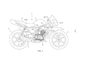
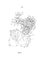
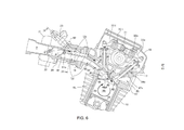
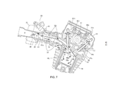
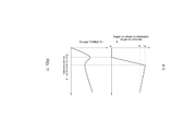
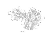
[0026] A Fig. 1 é uma elevação do lado direito de uma motocicleta em que está montado um motor de combustão interna com um sistema de admissão de acordo com uma modalidade preferida da presente invenção; a Fig. 2 é uma elevação do lado direito, parcialmente em seção, do motor de combustão interna; a Fig. 3 é uma vista plana de um bloco cilíndrico; a Fig. 4 é uma vista de fundo de um cabeçote do cilindro; a Fig. 5 é uma vista ampliada mostrando uma superfície de teto de uma câmara de combustão; a Fig. 6 é uma seção de uma parte principal do motor de combustão interna mediante condição de baixa carga; a Fig. 7 é uma seção da parte principal do motor de combustão interna mediante uma condição de meia carga; a Fig. 8 é uma seção da parte principal do motor de combustão interna mediante uma condição de alta carga; a Fig. 9 é uma seção tomada na linha IX-IX na Fig. 6; a Fig. 10 é uma seção tomada na linha X-X na Fig. 6; a Fig. 11 é um gráfico mostrando como um grau de abertura Φ de uma válvula de distribuição de gás de admissão é controlado em relação a um grau de abertura de válvula borboleta θ e como uma razão de queda Rt muda; a Fig. 12 é uma seção de uma parte principal de um motor de combustão interna com um sistema de admissão de acordo com uma outra modalidade da invenção; a Fig. 13 é uma seção tomada na linha XIII-XIII na Fig. 12; e a Fig. 14 é um gráfico mostrando relações do grau de abertura Φ da válvula de distribuição de gás de sucção e uma razão de injeção de combustível r com relação ao grau de abertura de válvula borboleta θ na modalidade mostrada na Fig. 12.[0026] Fig. 1 is a right side elevation of a motorcycle on which an internal combustion engine with an intake system is mounted according to a preferred embodiment of the present invention; Fig. 2 is a right side elevation, partially in section, of the internal combustion engine; Fig. 3 is a plan view of a cylindrical block; Fig. 4 is a bottom view of a cylinder head; Fig. 5 is an enlarged view showing a roof surface of a combustion chamber; Fig. 6 is a section of a main part of the internal combustion engine under low load condition; Fig. 7 is a section of the main part of the internal combustion engine under a half load condition; Fig. 8 is a section of the main part of the internal combustion engine under a high load condition; Fig. 9 is a section taken on line IX-IX in Fig. 6; Fig. 10 is a section taken on line X-X in Fig. 6; Fig. 11 is a graph showing how a degree of opening Φ of an inlet gas distribution valve is controlled relative to a degree of opening of a butterfly valve θ and how a drop rate Rt changes; Fig. 12 is a section of a main part of an internal combustion engine with an intake system according to another embodiment of the invention; Fig. 13 is a section taken on line XIII-XIII in Fig. 12; and Fig. 14 is a graph showing relationships of the degree of opening Φ of the suction gas distribution valve and a fuel injection ratio r with respect to the degree of opening of the butterfly valve θ in the embodiment shown in Fig. 12.
[0027] Uma modalidade da presente invenção será descrita com referência às Figs. 1 a 11 dos desenhos.[0027] An embodiment of the present invention will be described with reference to Figs. 1 to 11 of the drawings.
[0028] A Fig. 1 mostra, em elevação lateral, uma motocicleta 1 em que está montado um motor de combustão interna 10 com um sistema de admissão de acordo com a presente invenção.[0028] Fig. 1 shows, in side elevation, a
[0029] A motocicleta 1 tem uma estrutura de corpo 2 que inclui um par de tubulações de estrutura principal esquerda e direita 2b se estendendo para trás de um tubo frontal 2a. As tubulações de estrutura principal 2b se estendem para curvar para baixo depois da extensão para trás de modo a formar partes de inclinação em declive 2ba. As partes de inclinação em declive 2ba têm suas porções de extremidade inferior flexionadas para diante para terminar em extremidades inferiores.[0029] The
[0030] Um par de tubulações de estrutura descendente esquerda e direita 2c se estende com um declive acentuado a partir do tubo frontal 2a em arranjo substancialmente paralelo, em vista lateral, para as partes de inclinação em declive 2ba das tubulações de estrutura principal 2b.[0030] A pair of left and
[0031] Trilhos para o assento 2d se estendem para trás das extremidades superiores das partes de inclinação em declive 2ba das tubulações de estrutura principal 2b. Escoras traseiras 2e suportam os trilhos para o assento 2d que conectam porções do meio dos trilhos para o assento 2d e porções inferiores das partes de inclinação em declive 2ba.[0031] Rails for the
[0032] Um garfo frontal 3 é articuladamente conectado ao tubo frontal 2a da estrutura de corpo 2 da construção acima, e uma roda frontal 4 é giratoriamente suportada na extremidade inferior do garfo frontal 3. Uma placa de articulação 2f é fixamente anexada a porções inferiores das tubulações de estrutura principal 2b para se estender para a frente. Um garfo frontal 5 é articuladamente segurado na sua porção frontal à placa de articulação 2f e se estende para trás. As extremidades traseiras do garfo frontal 5 giratoriamente suportam uma roda traseira 6. Um amortecedor traseiro 7 é fornecido entre as extremidades traseiras do garfo frontal 5 e as porções de meio dos trilhos para o assento 2d.[0032] A
[0033] Nas tubulações de estrutura principal 2b é suportado um tanque de combustível 8, e um assento do condutor 9 é montado nos trilhos para o assento 2d em uma posição para trás do tanque de combustível 8.[0033] In the
[0034] O motor de combustão interna 10 montado na estrutura de corpo 2 é um motor do tipo SOHC, de 4 tempos com um cilindro único e duas válvulas. O motor 10 é montado na estrutura de corpo 2 com seu virabrequim 12 (Fig. 2) orientado na direção transversal da motocicleta e com seu cilindro levemente inclinado para a frente.[0034] The
[0035] Como mostrado na Fig. 2, um cárter 11 suportando um virabrequim 12 do motor de combustão interna 10 para rotação, tem nele um eixo principal 13 e um eixo secundário 14, que são dispostos na traseira do virabrequim 12, e um mecanismo de engrenagem 15 para mudança de velocidade é fornecido entre o eixo principal 13 e o eixo secundário 14. O eixo secundário 14 é um eixo de transmissão. Uma corrente (não mostrada) é passada entre o eixo secundário 14 e um eixo de uma roda traseira 6, por meio do que é transmitida força do eixo de transmissão para a roda traseira 6.[0035] As shown in Fig. 2, a
[0036] Com referência à Fig. 2, um bloco de cilindro 16, feito de uma fusão, tem nele uma camisa de cilindro 16L adaptada no bloco de cilindro 16 quando o bloco de cilindro 16 está fundido. O bloco de cilindro 16 é fixamente montado no cárter 11. Um cabeçote do cilindro 17 é fixamente montado no bloco de cilindro 16 via uma gaxeta e integralmente tensionado por cavilhas de estai com o bloco de cilindro 16. Uma cobertura do cabeçote do cilindro 18 cobre o cabeçote do cilindro 17 a partir de cima.[0036] Referring to Fig. 2, a
[0037] O bloco de cilindro 16, o cabeçote do cilindro 17 e a cobertura do cabeçote do cilindro 18, que são colocados no cárter 11, se estendem para cima do cárter 11 em uma forma levemente inclinada em direção à frente (vide Figs. 1 e 2).[0037] The
[0038] Do bloco de cilindro 16 levemente inclinado para diante do motor 10 montado na estrutura de corpo, se estende uma tubulação de entrada 20 através de uma tubulação de conexão 19. Na tubulação de entrada 20 é fornecido um corpo de acelerador 21 tendo uma válvula reguladora do tipo borboleta 22 nele. Um injetor de combustível 23 é anexado à tubulação de entrada 20. Uma válvula de distribuição de gás de admissão 61, a ser descrita em detalhes posteriormente, é também fornecida na tubulação de entrada 20.[0038] From the slightly forwardly
[0039] Como mostrado na Fig. 1, um filtro de ar 24 é conectado à extremidade traseira da tubulação de entrada 20. O filtro de ar 24 é disposto, em elevação lateral, em um espaço circundado pelas partes de inclinação em declive 2ba das tubulações de estrutura principal 2b, dos trilhos para o assento 2d e das escoras traseiras 2e.[0039] As shown in Fig. 1, an
[0040] Uma tubulação de escape 27 se estende para diante do cabeçote do cilindro 17 e é flexionada para baixo e então para trás para se estender para trás ao longo da superfície inferior do cárter 11 e, para adicionalmente, se estender para trás no lado direito da estrutura de corpo a ser conectada a um amortecedor 26 fornecido no lado direito da roda traseira 6.[0040] An
[0041] Com referência à Fig. 2, um cárter 11 é dividida em metades esquerda e direita cooperando para definir uma abertura entre elas, e a extremidade inferior da camisa de cilindro 16L na abertura para fazer com que o bloco de cilindro 16 se estenda para cima na atitude inclinada para diante. Um pistão 25 é, de modo deslizante adaptado em um furo do cilindro 16b definido pelo bloco de cilindro 16. Uma barra de conexão 26 é conectada a um pino de pistão 25p do pistão 25 e de um pino da manivela 12p do virabrequim 12 para formar um mecanismo da manivela.[0041] Referring to Fig. 2, a
[0042] Uma câmara de combustão 40 é formado entre uma face de topo 25t do pistão 25 reciprocando no furo do cilindro 16p do bloco de cilindro 16 e uma superfície de teto 41 do cabeçote do cilindro 17, a superfície de teto 41 estando em disposição de confronto com a face de topo 25t.[0042] A combustion chamber 40 is formed between a
[0043] A superfície de teto 41 do cabeçote do cilindro 17 é fornecida com uma abertura da válvula de admissão 42 e uma abertura da válvula de escape 43 (Figs. 4 e 6), que são dispostas em lados diametricamente opostos de um eixo cilíndrico C que é um eixo central do furo do cilindro 16b. A abertura da válvula de admissão e abertura da válvula de escape 42 e 43 abrem para a câmara de combustão 40. Das aberturas de válvula de admissão e de escape 42 e 43 se estendem portas de admissão e de escape 44 e 45 de conformação curvada, respectivamente, em direções para longe uma da outra.[0043] The
[0044] Como mostrado na Fig. 2, a porta de admissão 44 se estende da abertura da válvula de admissão 42 para trás da motocicleta e se comunica com a tubulação de entrada 20 através de uma tubulação de conexão 19, enquanto a porta de escape 45 é conectada a uma tubulação de escape 27 (Fig. 1).[0044] As shown in Fig. 2, the
[0045] Uma válvula de admissão 46 e uma válvula de escape 47 são, de modo deslizante, passadas através de guias de válvula 4i e 34e fixamente adaptadas no cabeçote do cilindro 16, respectivamente. A válvula de admissão 46 e a válvula de escape 47 são acionadas por um mecanismo de operação de válvula 30 fornecido acima do cabeçote do cilindro 13 para abrir e fechar a abertura da válvula de admissão 42 da porta de admissão 44 e da abertura da válvula de escape 43 da porta de escape 45, respectivamente, em sincronismo com a rotação do virabrequim 12.[0045] An
[0046] O mecanismo de operação de válvula 30 é para um motor de combustão interna do tipo SOHC e inclui um eixo de ressaltos 31 giratoriamente suportado acima do cabeçote do cilindro 17 para se estender transversalmente na motocicleta. Os eixos de braço oscilante 32i e 32e são suportados acima do eixo de ressaltos 31 em posições obliquamente para trás e para diante com relação ao eixo de ressaltos 31, respectivamente. Um eixo de braço oscilante 33i é, de modo oscilável, suportado na sua posição intermediária no eixo de braço oscilante traseiro 32i, e um braço oscilante de escape 33e é, de modo oscilável, suportado na sua posição intermediária no eixo de braço oscilante frontal 32e.[0046] The
[0047] Uma extremidade do braço oscilante de admissão 33i está em contato com um ressalto de excêntrico de admissão no eixo de ressaltos 31, enquanto a outra extremidade do braço oscilante de admissão 33i está em contato via um parafuso de ajuste com a extremidade superior de um suporte de válvula 46s da válvula de admissão 46, que é elasticamente impulsionada para cima. Uma extremidade do braço oscilante de escape 33e está em contato com um ressalto de excêntrico de escape no eixo de ressaltos 31, enquanto a outra extremidade do braço oscilante de escape 33e está em contato via um parafuso de ajuste com a extremidade superior de um suporte de válvula 47s da válvula de admissão 47, que é elasticamente impulsionada para cima. O braço oscilante de admissão 31i e o braço oscilante de escape 33e são induzidos a oscilar pela rotação do eixo de ressaltos 31 para abrir e fechar a válvula de admissão 46 e a válvula de escape 47.[0047] One end of the inlet swingarm 33i is in contact with an inlet cam boss on the
[0048] A Fig. 3 mostra uma vista plana do bloco de cilindro 16. O bloco de cilindro 16 tem uma superfície superior 16f correspondendo com uma superfície do cabeçote do cilindro 17. A superfície de correspondência 16f é formada com um orifício circular definindo o furo do cilindro 16b e um orifício retangular definindo uma câmara de corrente 16c em que a corrente de transmissão para transmitir força ao mecanismo de operação de válvula 30 é passada.[0048] Fig. 3 shows a plan view of the
[0049] A Fig. 4 mostra uma vista de fundo do cabeçote do cilindro 17 posta no bloco de cilindro 16. O cabeçote do cilindro 17 tem uma superfície inferior 17f correspondendo com a superfície de correspondência superior do bloco de cilindro 16. A superfície de correspondência 17f é formada com uma superfície de teto 41 em recesso definindo uma câmara de combustão 40 junto com o furo do cilindro 16b e uma câmara de corrente 17c se comunicando com a câmara de corrente 16c.[0049] Fig. 4 shows a bottom view of the
[0050] A superfície de teto 41 definindo a câmara de combustão 40 tem uma borda de abertura circular 41s na superfície inferior 17f do cabeçote do cilindro 17. A borda de abertura circular 41s coincide com o orifício circular definindo o furo do cilindro 16b.The
[0051] A abertura da válvula de admissão 42 de um diâmetro maior abre na parte de trás da superfície de teto 41, enquanto a abertura de escape 43 de um diâmetro menor do que a abertura da válvula de admissão 42 abre na frente da superfície de teto 41.[0051] The inlet valve opening 42 of a larger diameter opens at the rear of the
[0052] A superfície de teto 41 é formada com um orifício de plugue 48 do qual um plugue de ignição (não mostrado) se projeta.[0052]
[0053] A Fig. 5 mostra uma vista ampliada da câmara de combustão 40 do cabeçote do cilindro 17 como visto na direção do eixo cilíndrico C. Como mostrado, a abertura da válvula de admissão 42 é posicionada e formada em uma maneira em afastamento, como visto na direção do eixo cilíndrico, de modo que a parte periférica da abertura da válvula de admissão 42 se projeta radialmente para fora da borda de abertura circular 41s da superfície de teto 41, na superfície de correspondência 17f, i.e., radialmente para fora da abertura circular do furo do cilindro 16b. Em outras palavras, a abertura da válvula de admissão 42 tem uma porção abaulada conformada crescente 42a (uma porção pontilhada na Fig. 5) projetando-se radialmente para fora da borda de abertura circular 41s da superfície de teto.[0053] Fig. 5 shows an enlarged view of the combustion chamber 40 of the
[0054] Se a razão do comprimento circunferencial da porção abaulada 42a com relação ao comprimento circunferencial total da borda da abertura 42s da abertura da válvula de admissão 42, for chamada uma “razão de cobrimento Rm”, é desejável que a razão de cobrimento Rm como um resultado do afastamento da abertura da válvula de admissão 42 seja de aproximadamente de 20 a 50%.[0054] If the ratio of the circumferential length of the
[0055] Como mostrado na Fig. 5, a superfície de teto 41 tem um recesso conformado em cúpula 51 de uma conformação oval com um eixo mais longo dele envolvendo tanto a abertura da válvula de admissão 42 quanto a abertura de escape 43. Áreas conformadas crescentes 52 são formadas nos dois lados transversais do recesso conformado em cúpula 51 dentro da superfície de teto 41, para produzir esguichos aí.[0055] As shown in Fig. 5, the
[0056] Um par de superfícies de parede de guia opostas, curvadas 53 é formado em torno da periferia da abertura da válvula de admissão 42. As superfícies de parede de guia 53 se estendem divergentemente de posições adjacentes das duas extremidades da porção abaulada conformada crescente 42a da abertura da válvula de admissão 42 em direção à abertura de escape 43 ao longo da borda de abertura 42s da abertura da válvula de admissão 42.[0056] A pair of opposing, curved guide wall surfaces 53 is formed around the periphery of the
[0057] Em relação à formação acima da superfície de teto 41 da câmara de combustão 40 do cabeçote do cilindro 17, o furo do cilindro 16b do bloco de cilindro 16 é formado como mostrado nas Figs. 3, 6, 7 e 8. Isto é, uma superfície chanfrada arqueada 55 é formada em uma porção traseira da borda da abertura do furo do cilindro 16b, faceando o cabeçote do cilindro 17. A superfície chanfrada 55 é formada em oposição à porção abaulada 42a da abertura da válvula de admissão 42 e é chanfrada na direção de abertura da válvula de admissão 46 e ao longo da periferia do cabeçote da válvula 46pf da válvula de admissão 46 para uma extensão equivalente à posição máxima de elevação da válvula de admissão 46.[0057] In relation to the formation above the
[0058] Como mostrado nas Figs. 7, 8 e 9, a superfície chanfrada 55 é formada através de corte oblíquo de uma porção do bloco de cilindro 16 fundido de uma liga de alumínio em que a camisa de cilindro 16L é adaptada fundida. A porção de corte oblíquo do bloco de cilindro 16 é uma porção cobrindo uma abertura superior menos-flange da camisa de cilindro 16L.[0058] As shown in Figs. 7, 8 and 9, the chamfered
[0059] A porção periférica do cabeçote da válvula 46pf da válvula de admissão 46 é movida ao longo e em proximidade imediata da superfície chanfrada 55. Por esta razão, o gás de admissão que está fluindo no lado externo da abertura da válvula de admissão 42 (no lado da porção abaulada 42a) é forçado para passar através de uma folga extremamente pequena entre a superfície chanfrada 55 e a porção periférica do cabeçote da válvula 46pf da válvula de admissão 46 durante o movimento de abertura da válvula de admissão 46 para sua posição de elevação máxima, de modo que a sucção do gás de admissão através desta válvula para a câmara de combustão 40 é quase impedida com um efeito de cobrimento.[0059] The peripheral portion of the valve head 46pf of the
[0060] Uma vez que o gás de admissão, via o lado externo da abertura da válvula de admissão 42, é coberto para permitir que somente uma quantidade extremamente pequena do gás de admissão flua para a câmara de combustão 40, o gás de admissão é permitido fluir principalmente via o lado interno da abertura da válvula de admissão 42. Por conseguinte, é fornecida uma estrutura para facilmente produzir uma queda na câmara de combustão.[0060] Since the inlet gas, via the outside of the
[0061] A superfície chanfrada 55 pode ser formada de modo que a posição de elevação máxima da válvula de admissão 46 seja levemente além da superfície chanfrada 55.[0061] The chamfered
[0062] Como mostrado na Fig. 6, uma porção periférica da face de topo 25t do pistão 25, em oposição à porção abaulada 42a da abertura da válvula de admissão 42, é chanfrada em paralelo à superfície externa cilíndrica do cabeçote da válvula 46pf da válvula de admissão 46 para formar uma superfície chanfrada 56 no pistão 25. No percurso de sucção, o pistão 25 é movido para baixo e a válvula de admissão 46 é elevada e aberta. Durante esse percurso de sucção, a direção do gás de admissão que está fluindo via o lado externo da abertura da válvula de admissão 42 é feita perpendicular à superfície chanfrada 56 do pistão de modo que o gás de admissão que flui via o lado externo da abertura da válvula de admissão 42 para a câmara de combustão 40 é ainda suprimida para atingir um efeito preventivo de produção de queda.[0062] As shown in Fig. 6, a peripheral portion of the
[0063] O sistema de admissão como descrito acima é fornecido com uma passagem de admissão P se estendendo da tubulação de entrada 20 para a porta de admissão 44 através da tubulação de conexão 19. A passagem de admissão P é seccionada ou dividida por uma placa divisória 60 para uma passagem de admissão superior Passagem superior e uma passagem de admissão inferior Lp. A placa divisória 60 se estende da porção a jusante da tubulação de entrada 20 para a porção curvada da porta de admissão 44.[0063] The inlet system as described above is provided with an inlet passage P extending from inlet piping 20 to
[0064] A placa divisória 60 é formada integral com a tubulação de entrada 20. A extremidade a montante da placa divisória 60 é posicionada na tubulação de entrada 20 para dividir o interior da tubulação de entrada 20 para espaços superior e inferior. A extremidade a jusante da placa divisória 60 se estende para a porta de admissão 44.[0064] The
[0065] Como mostrado na Fig. 9, a placa divisória 60 tem uma extensão como uma faixa cujas bordas laterais opostas se estendem ao longo da superfície interna da porta de admissão 44.[0065] As shown in Fig. 9, the
[0066] A placa divisória 60 está em posição inclinada para cima na passagem de admissão P de modo que a área de seção transversal da passagem de admissão superior Up seja menor do que aquela da passagem de admissão inferior Lp.[0066] The
[0067] A extensão como uma faixa da placa divisória 60 é curvada ao longo da conformação curvada da porta de admissão 44, e, como mostrado na Fig. 10, a extremidade a jusante 60e (Fig. 10) da placa divisória 60 alcança o suporte de válvula 46s da válvula de admissão 46 posicionada na porção curvada da porta de admissão 44. A extremidade a jusante 60e é formada com um recesso conformado em U 60u côncavo da borda a jusante da placa divisória 60. O suporte de válvula 46s da válvula de admissão se estende através do recesso 60u.The band-like extension of the
[0068] A extremidade a jusante 60e é uma placa planar não curvada e se estende linearmente para a porção curvada das portas de admissão 44. As bordas laterais opostas da extremidade a jusante 60e são inseridas e fixadas em posição nas ranhuras opostas esquerda e direita 44v formadas na parede interna da porção curvada das portas de admissão 44.[0068] The
[0069] Na tubulação de entrada 20 é fornecida uma válvula de distribuição de gás de admissão 61 em uma posição a jusante da válvula borboleta 22 e a montante da placa divisória 60.[0069] In the
[0070] Com referência às Figs. 6, 7 e 8, a válvula de distribuição de gás de admissão 61 é uma válvula unidirecional que tem na sua extremidade proximal um eixo de articulação 61a fornecido na tubulação de entrada 20 e posicionado adjacente à extremidade a montante da placa divisória 60. A extremidade livre da válvula de distribuição de gás de admissão 61 é direcionada na direção a montante e pode ser inclinada para cima e para baixo por meio de um mecanismo de acionamento do motor 62.[0070] Referring to Figs. 6, 7 and 8, the inlet
[0071] Uma vez que a extremidade a montante da válvula de distribuição de gás de admissão 61 é direcionada para a válvula borboleta 22 posicionada a montante dela e é inclinada, a válvula de distribuição de gás de admissão 61 opera para distribuir o gás de admissão que está fluindo a jusante da válvula borboleta 22 na direção para cima ou na direção para baixo para mudar a razão do gás de admissão que está fluindo para a passagem de admissão superior Up e para a passagem de admissão inferior Lp.[0071] Since the upstream end of the inlet
[0072] Uma ECU (unidade eletrônica de controle) 65 (Fig. 2) para controlar o motor de combustão interna 10 é fornecida com um controlador de gás de admissão 66, e uma válvula borboleta 22 e um injetor de combustível 23 pertencendo ao sistema de admissão, são controlados pelo controlador de gás de admissão 66 que analisa as condições de operação do motor de combustão interna 10. A válvula de distribuição de gás de admissão 61 é também controlada pelo controlador de gás de admissão 66.[0072] An ECU (electronic control unit) 65 (Fig. 2) for controlling the
[0073] Com referência à Fig. 6, o grau de abertura θ da válvula borboleta 22 indica a condição de carga do motor 10, e o grau de abertura completa é alcançado quando a válvula borboleta 22 muda de uma posição completamente fechada para um estado em que a válvula está em paralelo com a direção de fluxo da passagem de admissão.[0073] Referring to Fig. 6, the degree of opening θ of the
[0074] A válvula de distribuição de gás de admissão 61 é controlada para oscilar de acordo com as condições de carga do motor 10. A válvula de distribuição de gás de admissão 61 tem um ângulo da válvula de distribuição de gás de admissão Φ, que é um ângulo oscilante. A válvula do ângulo da válvula de distribuição de gás de admissão Φ é zero (0) na condição de baixa carga mostrada na Fig. 6, e aumenta na direção para a direita como visto na Fig. 6.[0074] The inlet
[0075] O estado da queda é expressado por uma razão de queda Rt que é o número de rotação de correntes em turbilhão da queda por rotação do virabrequim 12.[0075] The slump state is expressed by a slump ratio Rt which is the number of whirling current rotations of the slump per
[0076] A razão de queda Rt=Velocidade angular rotacional/Velocidade angular do virabrequim.[0076] The fall ratio Rt=Rotational Angular Velocity/Crankshaft Angular Velocity.
[0077] Quanto maior a razão da queda Rt, maior é a corrente em turbilhão da queda.[0077] The greater the fall ratio Rt, the greater the eddy current of the fall.
[0078] A Fig. 11 mostra variações do ângulo da válvula de distribuição de gás de admissão Φ e da razão de queda Rt em relação ao grau de abertura de válvula borboleta θ, o ângulo da válvula de distribuição de gás de admissão Φ sendo o ângulo da válvula de distribuição de gás de admissão 61, que é variada em relação ao grau de abertura de válvula borboleta θ.[0078] Fig. 11 shows variations of the angle of the intake gas distribution valve Φ and the rate of drop Rt in relation to the degree of opening of the butterfly valve θ, the angle of the intake gas distribution valve Φ being the angle of inlet
[0079] Como a válvula de distribuição de gás de admissão 61 é controlada em relação às condições de carga do motor de combustão interna 10 será considerado junto com a razão de queda Rt, com referência à Fig. 11.[0079] How the inlet
[0080] Quando o motor 10 está operando sob uma condição de baixa carga, a válvula borboleta 22 abre levemente (grau de abertura de válvula borboleta θ é pequeno) como indicado na Fig. 6 e a válvula de distribuição de gás de admissão 61 está em uma posição de baixa carga (o ângulo da válvula de distribuição de gás de admissão Φ é zero) em que a extremidade distal da válvula 61 está em contato com a parede interna inferior da passagem de admissão P. Consequentemente, a válvula de distribuição de gás de admissão 61 opera para fazer com que a maior parte do gás de admissão flua para cima para a passagem de admissão superior Up.[0080] When the
[0081] Uma vez que o fluxo de gás de admissão passa através de uma pequena folga formada pela válvula borboleta 22 e é, na maioria das vezes, induzido para fluir através da passagem de admissão superior Up, que tem uma área em corte transversal relativamente pequena para a passagem de admissão inferior Lp, o gás de admissão é feito fluir em uma velocidade aumentada na passagem de admissão superior Up. Adicionalmente, o fluxo de gás de admissão é guiado para a vizinhança da abertura da válvula de admissão 42 pela placa divisória 60 estendida para o suporte de válvula de admissão 46s posicionado na porção curvada da porta de admissão 44. Consequentemente, uma porção maior do gás de admissão é sugada para a câmara de combustão 40 em uma velocidade aumentada ao longo da borda interna (a borda próxima do eixo cilíndrico C) da abertura da válvula de admissão 42. Por conseguinte, uma queda com fortes correntes em turbilhão é produzida (a razão de queda Rt aumenta) como indicado na Fig. 6.[0081] Since the inlet gas flow passes through a small gap formed by the
[0082] A abertura da válvula de admissão 42 é formada afastada de modo a ter a porção abaulada conformada crescente 42a projetando-se radialmente para fora do orifício cilíndrico do furo do cilindro 16b, e a lateral da borda externa (o lado da porção abaulada conformada crescente 42a) da abertura da válvula de admissão 42 é ocultada. Além disso, quase não existe fluxo de gás de admissão passando através da passagem de admissão inferior Lp, de modo que o fluxo de gás de admissão quase não flui para a câmara de combustão 40 via a borda lateral externa da abertura da válvula de admissão 42. Como uma consequência, nenhum fluxo antiqueda resistindo às correntes em turbilhão da queda é produzido, por meio do que, o fluxo de queda é fortemente produzido com razão de queda Rt. Por conseguinte, a eficiência de combustão na condição de baixa carga é aumentada.[0082] The opening of the
[0083] Quando o motor 10 está operando em uma condição de meia carga, a válvula borboleta 22 é aberta para um grau de abertura médio (o grau de abertura de válvula borboleta θ é intermediário) como mostrado na Fig. 7, e a válvula de distribuição de gás de admissão 61 está em uma posição de meia carga (o ângulo da válvula de distribuição de gás de admissão Φ é β) em que a extremidade distal da válvula 61 aborda a parede interna superior da passagem de admissão P. Consequentemente, a válvula de distribuição de gás de admissão 61 opera para fazer com que uma quantidade menor do gás de admissão flua para cima do que para baixo.[0083] When the
[0084] Consequentemente, uma quantidade suficiente do gás de admissão flui para a passagem de admissão inferior Lp, enquanto o fluxo de gás de admissão na passagem de admissão superior Up é suprimido, como mostrado pelas setas na Fig. 7.[0084] Consequently, a sufficient amount of the inlet gas flows into the lower inlet passage Lp, while the inlet gas flow in the upper inlet passage Up is suppressed, as shown by the arrows in Fig. 7.
[0085] Por conseguinte, o fluxo de gás de admissão suprimido na passagem de admissão superior Up pode produzir somente uma queda de uma corrente em turbilhão fraca mesmo o gás de admissão flua para a câmara de combustão 40 ao longo da borda interna da abertura da válvula de admissão 42 porque o fluxo de gás de admissão suprimido é fraco. Adicionalmente, mesmo que exista algum fluxo de gás de admissão ao longo da borda externa da abertura da válvula de admissão 42 para a câmara de combustão 40, tal fluxo de gás de admissão cria uma queda contrária resistindo à queda, de modo que a queda é suprimida e a razão de queda Rt é reduzida.[0085] Therefore, the suppressed inlet gas flow in the upper inlet passage Up can only produce a drop of a weak eddy current even though the inlet gas flows into the combustion chamber 40 along the inner edge of the opening of the
[0086] Quando o motor 10 está operando em uma condição de alta carga, a válvula borboleta 22 está completamente aberta (o grau de abertura de válvula borboleta θ está totalmente aberto) como mostrado na Fig. 8, e a válvula de distribuição de gás de admissão 61 está em uma posição de alta carga (o ângulo da válvula de distribuição de gás de admissão Φ é α) em que a válvula 61 toma uma atitude coplanar com a placa divisória 60. Consequentemente, a válvula de distribuição de gás de admissão 61 opera para fazer a taxa de distribuição igual para a taxa das áreas em seção transversal das passagens superior e inferior divididas pela placa divisória 60.[0086] When the
[0087] Por conseguinte, existem suficientes quantidades do fluxo de gás de admissão tanto na passagem de gás de admissão superior quanto na inferior Up e Lp como mostrado na Fig. 8. O fluxo de gás de admissão na passagem de admissão superior Up é sugado para a câmara de combustão 40 ao longo da borda interna da abertura da válvula de admissão 42 para, por conseguinte, produzir uma queda. Por outro lado, o fluxo de gás de admissão na passagem de admissão inferior Lp é sugado, enquanto está sendo ocultado, na câmara de combustão 40 ao longo da borda externa da abertura da válvula de admissão 42 para produzir uma queda contrária. No entanto, uma vez que suficiente quantidade do gás de admissão que está fluindo da passagem de admissão superior Up para a câmara de combustão, uma queda de uma razão de queda relativamente alta Ri com correntes em turbilhão apropriadamente fortes é produzida para atingir uma boa eficiência de admissão acompanhada por um gás de admissão suficiente.[0087] Therefore, there are sufficient amounts of the inlet gas flow in both the upper and lower inlet gas passage Up and Lp as shown in Fig. 8. The inlet gas flow in the upper inlet passage Up is sucked to the combustion chamber 40 along the inner edge of the inlet valve opening 42 to thereby produce a drop. On the other hand, the inlet gas flow in the lower inlet passage Lp is sucked, while being concealed, into the combustion chamber 40 along the outer edge of the inlet valve opening 42 to produce a back drop. However, since sufficient amount of the inlet gas is flowing from the upper inlet passage Up to the combustion chamber, a drop of a relatively high drop rate Ri with suitably strong eddy currents is produced to achieve good efficiency. inlet accompanied by a sufficient inlet gas.
[0088] Como descrito acima, o sistema de admissão do motor 10 pode ajustar o grau das correntes em turbilhão da queda produzida, dependendo da condição de carga do motor, para, por conseguinte, realizar uma eficiência de combustão apropriada.[0088] As described above, the
[0089] A válvula de distribuição de gás de admissão 61 está na forma de uma válvula unidirecional tendo um eixo de articulação 61a suportado na tubulação de entrada 20 e posicionado adjacente a e a montante da extremidade a montante da placa divisória 60 e tendo um corpo chato que é oscilável para cima e para baixo e do qual a extremidade a montante é direcionada na direção a montante. A posição tomada pela extremidade a montante da válvula de distribuição de gás de admissão 61 como um resultado do seu movimento de oscilação torna confiável mudar a distribuição para cima e para baixo do gás de admissão.[0089] The inlet
[0090] No sistema de admissão de acordo com a modalidade descrita acima, o injetor de combustível 23 é fornecido somente na passagem de admissão superior Up entre as passagens superior e inferior Up e Lp dividido pela placa divisória 60, o injetor de combustível pode também ser fornecido na passagem de admissão inferior Lp. Tal modalidade é mostrada nas Figs. 12 e 13.[0090] In the intake system according to the modality described above, the
[0091] Como mostrado, um injetor de combustível superior 71 é fornecido na passagem de admissão superior Up, enquanto um injetor de combustível inferior 72 é fornecido na passagem de admissão inferior Lp. Os mesmos sinais de referência são usados para elementos equivalentes na modalidade descrita acima.[0091] As shown, an
[0092] A Fig. 14 mostra uma taxa de injeção de combustível r do injetor de combustível inferior 72 e do injetor de combustível superior 71, a taxa r sendo “a quantidade de injeção de combustível inferior/a quantidade de injeção de combustível superior”.[0092] Fig. 14 shows a fuel injection rate r of the
[0093] Como mostrado, conforme o grau de abertura de válvula borboleta θ aumenta, o grau de abertura da válvula de distribuição de gás de admissão Φ simplesmente aumenta de zero (0) grau na condição de baixa carga até grau α na condição de alta carga.[0093] As shown, as butterfly valve opening degree θ increases, inlet gas distribution valve opening degree Φ simply increases from zero (0) degree in low load condition to degree α in high condition charge.
[0094] Na condição de baixa carga, em que o gás de admissão flui somente na passagem de admissão superior Up, a taxa de injeção de combustível r é zero (0) % onde o injetor de combustível inferior 72 não injeta combustível e somente o injetor de combustível superior 71 injeta combustível.[0094] In the low load condition, where the inlet gas flows only in the upper intake passage Up, the fuel injection rate r is zero (0) % where the
[0095] Quando o grau de abertura de válvula borboleta θ aumenta acompanhado por aumento da carga, o grau de abertura da válvula de distribuição de gás de admissão Φ é aumentado para aumentar a taxa da quantidade do gás de admissão que está fluindo na passagem de admissão inferior Lp em relação à quantidade do gás de admissão que está fluindo na passagem de admissão superior Up. Simultaneamente, a quantidade de combustível injetada pelo injetor de combustível inferior 72 é aumentada para aumentar a taxa de injeção de combustível r.[0095] When the opening degree of butterfly valve θ increases accompanied by increased load, the opening degree of the inlet gas distribution valve Φ is increased to increase the rate of the amount of inlet gas that is flowing in the passage of lower intake Lp in relation to the amount of intake gas flowing in the upper intake passage Up. Simultaneously, the amount of fuel injected by the
[0096] Quando a carga aumenta para a condição de alta carga, a taxa de injeção de combustível r é feita para ser aproximadamente equivalente à razão das áreas em seção transversal na passagem de admissão P dividido pela placa divisória 60 (a razão do gás de admissão flui nas passagens superior e inferior Up e Lp).[0096] When the load increases for the high load condition, the fuel injection rate r is made to be approximately equivalent to the ratio of the cross-sectional areas in the inlet passage P divided by the partition plate 60 (the gas ratio of intake flows in the upper and lower passages Up and Lp).
[0097] O controle das quantidades de injeção de combustível (taxa de injeção de combustível r) dos injetores de combustível inferior e superior 72 e 71, de acordo com a posição de oscilação da válvula de distribuição de gás de admissão 61, em outras palavras, a taxa de distribuição de gás de admissão (grau de abertura da válvula de distribuição de gás de admissão Φ). Como descrito acima, a eficiência de combustão é aumentada e a razão ar/combustível (A/F) pode se tornar mais apropriada. DESCRIÇÃO DOS SINAIS DE REFERÊNCIA 1...Motocicleta, 2...Estrutura de corpo, 10...Motor de combustão interna, 11...Cárter, 12...Virabrequim, 13...Eixo principal, 14...Eixo secundário, 16...Bloco de cilindro, 16b... furo do cilindro, 17...Cabeçote do cilindro, 18...Cobertura do cabeçote do cilindro, 19...Tubulação de conexão, 20.1. Tubulação de entrada, 21...Corpo de borboleta, 22...Válvula borboleta, 23...Injetor de combustível, 24...Filtro de ar, 25...Pistão, 26...Barra de conexão, 20.2. Mecanismo de movimento da válvula, 31...Eixo de ressaltos, 32e, 32i... eixo de braço oscilante, 33i... Braço oscilante de admissão, 33e...Braço oscilante de escape, 34i, 34e...Guia de válvula, 20.3. Câmara de combustão, 41...Superfície de teto, 42...Abertura da válvula de admissão, 42a...Porção abaulada, 43...Abertura da Válvula de escape, 44...Porta de admissão, 45...Porta de escape, 46...Válvula de admissão, 46pf...Cabeçote de válvula, 46s...Suporte de válvula de admissão, 47...Válvula de escape, 48...Orifício de plugue, 20.4. Recesso conformado em cúpula, 52...Esguicho, 53...Superfície da parede de guia, 55...Superfície chanfrada, 56...Superfície chanfrada do pistão, 20.5. Placa divisória, 61...Válvula de distribuição de gás de admissão, 62...Mecanismo de acionamento do motor, 65...ECU, 66...Controlador do gás de admissão, 71...Injetor de combustível superior, 72...Injetor de combustível inferior, Up...Passagem de admissão superior, Lp...Passagem de admissão inferior, P...Passagem de admissão[0097] The control of fuel injection quantities (fuel injection rate r) of the lower and
Claims (5)
Applications Claiming Priority (3)
| Application Number | Priority Date | Filing Date | Title |
|---|---|---|---|
| JP2012-082788 | 2012-03-30 | ||
| JP2012082788 | 2012-03-30 | ||
| PCT/JP2013/058632 WO2013146703A1 (en) | 2012-03-30 | 2013-03-25 | Air intake device for internal combustion engine |
Publications (3)
| Publication Number | Publication Date |
|---|---|
| BR112014019110A2 BR112014019110A2 (en) | 2017-06-20 |
| BR112014019110A8 BR112014019110A8 (en) | 2017-07-11 |
| BR112014019110B1 true BR112014019110B1 (en) | 2021-11-09 |
Family
ID=49259954
Family Applications (1)
| Application Number | Title | Priority Date | Filing Date |
|---|---|---|---|
| BR112014019110-7A BR112014019110B1 (en) | 2012-03-30 | 2013-03-25 | INTERNAL COMBUSTION ENGINE INLET SYSTEM |
Country Status (8)
| Country | Link |
|---|---|
| JP (1) | JP5925878B2 (en) |
| CN (1) | CN104114832B (en) |
| AR (1) | AR094131A1 (en) |
| BR (1) | BR112014019110B1 (en) |
| CO (1) | CO7141440A2 (en) |
| PE (1) | PE20142191A1 (en) |
| PH (1) | PH12014502192A1 (en) |
| WO (1) | WO2013146703A1 (en) |
Families Citing this family (11)
| Publication number | Priority date | Publication date | Assignee | Title |
|---|---|---|---|---|
| JP6262587B2 (en) * | 2014-03-28 | 2018-01-17 | 本田技研工業株式会社 | Intake structure of internal combustion engine |
| JP6215807B2 (en) * | 2014-09-30 | 2017-10-18 | 本田技研工業株式会社 | Intake device for internal combustion engine |
| JP6212014B2 (en) * | 2014-09-30 | 2017-10-11 | 本田技研工業株式会社 | Intake device for internal combustion engine |
| CN105986879A (en) * | 2015-02-09 | 2016-10-05 | 苏州英特模汽车科技有限公司 | Internal combustion engine intake tumble automatic regulating system |
| CN106286042A (en) * | 2015-06-18 | 2017-01-04 | 上海银轮热系统科技有限公司 | A Novel section-variable and tumble flow gas handling system |
| ITUB20153744A1 (en) * | 2015-09-18 | 2017-03-18 | Maserati Spa | VARIABLE GEOMETRY SUCTION DUCT FOR AN INTERNAL COMBUSTION ENGINE. |
| JP6439070B1 (en) | 2017-07-05 | 2018-12-19 | 本田技研工業株式会社 | Intake structure of internal combustion engine |
| JP7027862B2 (en) * | 2017-12-14 | 2022-03-02 | トヨタ紡織株式会社 | Intake pipe connection structure |
| JP6994998B2 (en) * | 2018-03-29 | 2022-01-14 | 本田技研工業株式会社 | engine |
| JP7306832B2 (en) * | 2019-01-29 | 2023-07-11 | ダイハツ工業株式会社 | cylinder head |
| CN115013142A (en) * | 2022-04-28 | 2022-09-06 | 一汽解放汽车有限公司 | Engine combustion system |
Family Cites Families (10)
| Publication number | Priority date | Publication date | Assignee | Title |
|---|---|---|---|---|
| JPH05223040A (en) * | 1992-02-07 | 1993-08-31 | Mazda Motor Corp | Intake device for engine |
| JP3671755B2 (en) * | 1999-08-13 | 2005-07-13 | 日産自動車株式会社 | Intake control device for direct injection internal combustion engine |
| JP3840871B2 (en) * | 2000-03-14 | 2006-11-01 | 日産自動車株式会社 | Compression self-ignition gasoline engine |
| JP3695401B2 (en) * | 2002-02-13 | 2005-09-14 | 日産自動車株式会社 | Intake device for internal combustion engine |
| JP2005180247A (en) * | 2003-12-17 | 2005-07-07 | Nissan Motor Co Ltd | Intake air control device of in-cylinder direct injection type internal combustion engine |
| JP4412118B2 (en) * | 2004-09-06 | 2010-02-10 | 日産自動車株式会社 | Intake device for internal combustion engine |
| JP4728195B2 (en) * | 2006-09-20 | 2011-07-20 | ヤマハ発動機株式会社 | Engine intake control device |
| JP2008151078A (en) * | 2006-12-20 | 2008-07-03 | Suzuki Motor Corp | Engine air-intake device |
| JP2008155925A (en) * | 2006-12-21 | 2008-07-10 | Fuji Seal International Inc | Article packaging case |
| JP2009264158A (en) * | 2008-04-23 | 2009-11-12 | Toyota Motor Corp | Intake system for internal combustion engine |
-
2013
- 2013-03-25 PE PE2014001504A patent/PE20142191A1/en active IP Right Grant
- 2013-03-25 JP JP2014507873A patent/JP5925878B2/en active Active
- 2013-03-25 WO PCT/JP2013/058632 patent/WO2013146703A1/en active Application Filing
- 2013-03-25 BR BR112014019110-7A patent/BR112014019110B1/en active IP Right Grant
- 2013-03-25 CN CN201380008913.1A patent/CN104114832B/en active Active
- 2013-03-27 AR ARP130101056A patent/AR094131A1/en not_active Application Discontinuation
-
2014
- 2014-09-29 PH PH12014502192A patent/PH12014502192A1/en unknown
- 2014-09-29 CO CO14215166A patent/CO7141440A2/en unknown
Also Published As
| Publication number | Publication date |
|---|---|
| AR094131A1 (en) | 2015-07-15 |
| CO7141440A2 (en) | 2014-12-12 |
| BR112014019110A2 (en) | 2017-06-20 |
| PH12014502192A1 (en) | 2014-12-10 |
| JPWO2013146703A1 (en) | 2015-12-14 |
| CN104114832B (en) | 2016-09-07 |
| BR112014019110A8 (en) | 2017-07-11 |
| CN104114832A (en) | 2014-10-22 |
| WO2013146703A1 (en) | 2013-10-03 |
| PE20142191A1 (en) | 2014-12-27 |
| JP5925878B2 (en) | 2016-05-25 |
Similar Documents
| Publication | Publication Date | Title |
|---|---|---|
| BR112014019110B1 (en) | INTERNAL COMBUSTION ENGINE INLET SYSTEM | |
| JP4728195B2 (en) | Engine intake control device | |
| US7802555B2 (en) | Intake control device for an engine | |
| JP6000785B2 (en) | Intake device for internal combustion engine | |
| BRPI0520871B1 (en) | saddle-type motor vehicle | |
| BR112019017635B1 (en) | INTAKE STRUCTURE FOR INTERNAL COMBUSTION ENGINES | |
| BRPI0902560A2 (en) | vehicle drive unit and mounting type vehicle | |
| EP2101055B1 (en) | Engine with intake control device | |
| BR0318810B1 (en) | motorcycle. | |
| JP2007146815A (en) | Internal combustion engine | |
| JP6005465B2 (en) | Intake device for internal combustion engine | |
| JP3402640B2 (en) | Engine intake control device | |
| ES2680592T3 (en) | Structure for joining an exhaust gas sensor of an internal combustion engine | |
| JP3506769B2 (en) | Engine intake control device | |
| WO2023188249A1 (en) | Air intake structure for internal combustion engine | |
| JP2013213409A (en) | Intake device for internal combustion engine | |
| JP7493097B2 (en) | Intake structure of an internal combustion engine | |
| JP5908321B2 (en) | Internal combustion engine | |
| JP2004003424A (en) | Intake device for engine | |
| EP4123139A1 (en) | Intake structure for internal combustion engine | |
| KR100765613B1 (en) | A throttle plate lessened inflowing resistance | |
| JP4178889B2 (en) | Intake control device for fuel injection engine | |
| JP2887877B2 (en) | Engine intake control device | |
| JP6186299B2 (en) | Air intake structure for saddle-ride type vehicles | |
| BR102014006941A2 (en) | internal combustion engine and connecting rod |
Legal Events
| Date | Code | Title | Description |
|---|---|---|---|
| B06F | Objections, documents and/or translations needed after an examination request according [chapter 6.6 patent gazette] | ||
| B06U | Preliminary requirement: requests with searches performed by other patent offices: procedure suspended [chapter 6.21 patent gazette] | ||
| B09A | Decision: intention to grant [chapter 9.1 patent gazette] | ||
| B16A | Patent or certificate of addition of invention granted [chapter 16.1 patent gazette] |
Free format text: PRAZO DE VALIDADE: 20 (VINTE) ANOS CONTADOS A PARTIR DE 25/03/2013, OBSERVADAS AS CONDICOES LEGAIS. |