JP5908321B2 - Internal combustion engine - Google Patents
Internal combustion engine Download PDFInfo
- Publication number
- JP5908321B2 JP5908321B2 JP2012080063A JP2012080063A JP5908321B2 JP 5908321 B2 JP5908321 B2 JP 5908321B2 JP 2012080063 A JP2012080063 A JP 2012080063A JP 2012080063 A JP2012080063 A JP 2012080063A JP 5908321 B2 JP5908321 B2 JP 5908321B2
- Authority
- JP
- Japan
- Prior art keywords
- intake
- valve
- internal combustion
- combustion engine
- intake valve
- Prior art date
- Legal status (The legal status is an assumption and is not a legal conclusion. Google has not performed a legal analysis and makes no representation as to the accuracy of the status listed.)
- Expired - Fee Related
Links
Images
Classifications
-
- Y—GENERAL TAGGING OF NEW TECHNOLOGICAL DEVELOPMENTS; GENERAL TAGGING OF CROSS-SECTIONAL TECHNOLOGIES SPANNING OVER SEVERAL SECTIONS OF THE IPC; TECHNICAL SUBJECTS COVERED BY FORMER USPC CROSS-REFERENCE ART COLLECTIONS [XRACs] AND DIGESTS
- Y02—TECHNOLOGIES OR APPLICATIONS FOR MITIGATION OR ADAPTATION AGAINST CLIMATE CHANGE
- Y02T—CLIMATE CHANGE MITIGATION TECHNOLOGIES RELATED TO TRANSPORTATION
- Y02T10/00—Road transport of goods or passengers
- Y02T10/10—Internal combustion engine [ICE] based vehicles
- Y02T10/12—Improving ICE efficiencies
Landscapes
- Output Control And Ontrol Of Special Type Engine (AREA)
Description
本発明は、車両に搭載される内燃機関の吸気装置に関する。 The present invention relates to an intake device for an internal combustion engine mounted on a vehicle.
内燃機関の低負荷領域において、燃費の向上を図るために、燃焼室内で吸入された吸気がタンブルを発生し、燃焼室上部の点火プラグの周りに燃料を送り成層化して燃焼効率の向上を図る吸気装置を構成したものがある。 In order to improve fuel efficiency in the low load region of an internal combustion engine, intake air taken in the combustion chamber generates tumble, and fuel is sent around the spark plug at the upper portion of the combustion chamber to stratify the combustion efficiency. There is what constituted the intake device.
シリンダヘッドの燃焼室の天井面の吸気弁口と排気弁口から吸気ポートと排気ポートが互いに離れる方向に湾曲しながら延出しており、この吸気ポートが燃焼室に案内する吸気のうちで吸気弁口のシリンダ軸(シリンダボアの中心軸)に近い内側縁側から燃焼室に吸入される吸気が、排気側に向け流入しながらシリンダボアの排気側を下降した後にピストン頂面に沿って流れを曲げて吸気側を上昇することで縦渦いわゆるタンブルを形成する。 The intake port and the exhaust port extend from the intake valve port and the exhaust valve port on the ceiling surface of the combustion chamber of the cylinder head while curving in a direction away from each other. Of the intake air that is guided to the combustion chamber, the intake valve The intake air that is drawn into the combustion chamber from the inner edge near the cylinder shaft (the central axis of the cylinder bore) flows into the exhaust chamber while descending the exhaust side of the cylinder bore and then bending the flow along the piston top surface. A vertical vortex, so-called tumble, is formed by raising the side.
そこで、吸気弁口のシリンダ軸に近い内側縁側から吸入される吸気の割合を大きくするために、吸気ポートの内部を仕切壁により上下の通路に仕切り、仕切壁の上流側に下方の通路の開閉を行う吸気制御弁を設け、機関始動直後に下方の通路を閉じることで、吸気ポートの上方の通路を流れる吸気が上方の通路の延長である吸気弁口の内側縁側から吸入されることになり、強い渦流のタンブルを発生するようにした吸気装置の例がある(特許文献1参照)。 Therefore, in order to increase the proportion of the intake air from the inner edge near the cylinder shaft of the intake valve port, the inside of the intake port is partitioned into upper and lower passages by a partition wall, and the lower passage is opened and closed upstream of the partition wall. By providing an intake control valve that closes the lower passage immediately after engine startup, intake air flowing through the passage above the intake port is drawn from the inner edge of the intake valve port, which is an extension of the upper passage. There is an example of an intake device that generates a strong vortex tumble (see Patent Document 1).
特許文献1の吸気装置では、吸気ポートの仕切壁の上流側に設けられる吸気制御弁は、基端の軸部が吸気ポートの下壁に軸支されて回動し、下壁の内面に沿って伏せることで下方の通路の上流側開口を開き上下双方の通路を吸気が流れ、上方に回動して先端縁が仕切壁の上流端縁に接することで下方の通路の上流側開口が閉じられ、上方の通路のみを吸気が流れる。
したがって、機関始動直後は吸気制御弁が下方の通路の上流側開口を閉じ、上方の通路を吸気が流れ燃焼室に入ることで、強い渦流のタンブルを発生させ燃焼効率を上げている。
In the intake device of Patent Document 1, the intake control valve provided on the upstream side of the partition wall of the intake port rotates with the shaft portion at the base end pivotally supported by the lower wall of the intake port, along the inner surface of the lower wall. By opening up, the upstream opening of the lower passage is opened and the intake air flows through both the upper and lower passages. The upper edge of the lower passage is closed by rotating upward and the leading edge contacting the upstream edge of the partition wall. The intake air flows only through the upper passage.
Therefore, immediately after the engine is started, the intake control valve closes the upstream opening of the lower passage, and the intake air flows through the upper passage and enters the combustion chamber, thereby generating a strong vortex tumble and increasing the combustion efficiency.
仕切壁により内燃機関の負荷状態によらず全域で、タンブルは向上するため、中負荷から高負荷領域においては、タンブルの渦流が強すぎる傾向にあり、特に中負荷状態では急速燃焼により燃費の低減が妨げられ、また急速燃焼を原因としたクランク打音が発生することがある。 Because the partition wall improves the tumble throughout the region regardless of the load condition of the internal combustion engine, the tumble vortex tends to be too strong in the medium load to high load region, and particularly in the medium load state, fuel consumption is reduced by rapid combustion. May be disturbed, and cranking noise may occur due to rapid combustion.
そこで、中負荷領域では、タンブル発生量を抑制したいが、特許文献1の吸気制御弁による吸気制御では、上方の通路の上流側開口のみを部分的に閉じて上方の通路を流れる吸気を抑制することはできない。 Therefore, in the middle load region, it is desired to suppress the amount of tumble generated. However, in the intake control by the intake control valve of Patent Document 1, only the upstream side opening of the upper passage is partially closed to suppress the intake air flowing through the upper passage. It is not possible.
本発明は、かかる点に鑑みなされたもので、その目的とする処は、吸気バルブリフト量可変機構を備え、内燃機関の負荷状態に応じて吸気振分け弁と同時に吸気弁の最大バルブリフト量を制御してタンブルの渦流の強さを調整して燃焼効率の最適化を図ることができる内燃機関の吸気装置を供する点にある。 The present invention has been made in view of the above points, and an object of the present invention is to provide an intake valve lift variable mechanism, and to adjust the maximum valve lift of the intake valve simultaneously with the intake distribution valve according to the load state of the internal combustion engine. It is the point which provides the intake device of the internal combustion engine which can aim at the optimization of combustion efficiency by controlling and adjusting the strength of the tumble vortex.
上記目的を達成するために、請求項1記載の発明は、
シリンダブロック(16)のシリンダボア(16b)内を摺動自在に嵌合されるピストン(25)の頂面と同頂面が対向するシリンダヘッド(17)の天井面(41)との間に燃焼室(40)が構成され、
前記シリンダヘッド(17)の前記天井面(41)に開口した吸気弁口(42)と排気弁口(43)から各々吸気ポート(44)と排気ポート(45)が互いに離れる方向に湾曲しながら延出して形成され、
吸気ポート(44)にインレットパイプ(20)が接続されて連続した吸気通路(P)が構成され、
前記インレットパイプ(20)にスロットル弁(22)が設けられ、
前記吸気通路(P)が部分的に仕切板(60)により上側吸気通路(Up)と下側吸気通路(Lp)に仕切られ、
前記スロットル弁(22)よりも下流で前記仕切板(60)の上流に設けられた吸気振分け弁(61)により前記上側吸気通路(Up)と前記下側吸気通路(Lp)を流れる吸気が制御される内燃機関の吸気装置において、
前記吸気振分け弁(61)は、基端が前記インレットパイプに前記仕切板(60)の上流端縁の近傍で軸支されて吸気上流側に向けた先端を上下に揺動自在とし、
前記吸気弁口(42)を開閉する吸気弁(46)の最大バルブリフト量を変更する吸気バルブリフト量可変機構(90)と、
内燃機関の負荷状態に応じて前記吸気振分け弁(61)と前記吸気バルブリフト量可変機構(90)を駆動制御する吸気制御手段(66)とを備え、
前記吸気制御手段(66)は、
内燃機関が低負荷状態のときは、吸気を大部分上方に振り分けて前記上側吸気通路(Up)を流れるように前記吸気振分け弁(61)を位置決めするとともに、前記吸気バルブリフト量可変機構(90)を駆動して吸気弁(46)の最大バルブリフト量(D)を最小値(d1)に設定し、
内燃機関が中負荷状態のときは、吸気を下方より上方の割合を小さく振り分けて前記上側吸気通路(Up)を流れる吸気を抑制するように前記吸気振分け弁(61)を位置決めするとともに、前記吸気バルブリフト量可変機構(90)を駆動して吸気弁(46)の最大バルブリフト量(D)を中間値(d2)に設定し、
内燃機関が高負荷状態のときは、前記仕切板(60)に仕切られた割合に吸気を上下に振り分けるように前記吸気振分け弁(61)を位置決めするとともに、前記吸気バルブリフト量可変機構(90)を駆動して吸気弁(46)の最大バルブリフト量(D)を最大値(d3)に設定することを特徴とする内燃機関の吸気装置である。
In order to achieve the above object, the invention according to claim 1
Combustion between the top surface of the piston (25) slidably fitted in the cylinder bore (16b) of the cylinder block (16) and the ceiling surface (41) of the cylinder head (17) facing the top surface Chamber (40) is constructed,
While the intake port (44) and the exhaust port (45) are curved away from each other from the intake valve port (42) and the exhaust valve port (43) opened in the ceiling surface (41) of the cylinder head (17). Formed to extend,
An inlet pipe (20) is connected to the intake port (44) to form a continuous intake passage (P),
The inlet pipe (20) is provided with a throttle valve (22),
The intake passage (P) is partially partitioned into an upper intake passage (Up) and a lower intake passage (Lp) by a partition plate (60),
The intake air distribution valve (61) provided downstream of the throttle valve (22) and upstream of the partition plate (60) controls intake air flowing through the upper intake passage (Up) and the lower intake passage (Lp). In an internal combustion engine intake device,
The intake divergence valve (61) has a base end pivotally supported by the inlet pipe in the vicinity of the upstream end edge of the partition plate (60), and a tip end toward the intake upstream side is swingable up and down.
An intake valve lift variable mechanism (90) for changing the maximum valve lift of the intake valve (46) for opening and closing the intake valve port (42);
Intake control means (66) for driving and controlling the intake valve (61) and the intake valve lift variable mechanism (90) according to the load state of the internal combustion engine,
The intake control means (66)
When the internal combustion engine is in a low load state, the intake valve (61) is positioned so that the intake air is largely distributed upward and flows through the upper intake passage (Up), and the intake valve lift amount variable mechanism (90 ) To set the maximum valve lift (D) of the intake valve (46) to the minimum value (d1),
When the internal combustion engine is in a medium load state, the intake air distribution valve (61) is positioned so as to suppress the intake air flowing through the upper intake passage (Up) by distributing the intake air from a lower upper portion to a lower proportion, and the intake air Drive the valve lift variable mechanism (90) to set the maximum valve lift (D) of the intake valve (46) to the intermediate value (d2).
When the internal combustion engine is in a high load state, the intake distribution valve (61) is positioned so as to distribute intake air up and down in proportion to the partition plate (60), and the intake valve lift amount variable mechanism (90 ) To set the maximum valve lift (D) of the intake valve (46) to the maximum value (d3) .
請求項2記載の発明は、
請求項1記載の内燃機関の吸気装置において、
前記吸気制御手段(66)は、
内燃機関が中負荷状態から高負荷状態に移行するときは、吸気を下方より上方の割合を小さく振り分ける中負荷位置に位置決めされた前記吸気振分け弁(61)を仕切板に仕切られた割合に吸気を上下に振り分ける高負荷位置に駆動すると同時に、前記吸気バルブリフト量可変機構(90)を駆動して吸気弁(46)の最大バルブリフト量(D)を中間値(d2)から一度小さくしてから再び大きくして最大値(d3)に設定することを特徴とする。
The invention according to
The intake device for an internal combustion engine according to claim 1 ,
The intake control means (66)
When the internal combustion engine transitions from a medium load state to a high load state, the intake valve (61), which is positioned at a medium load position that distributes the intake air from a lower portion to a lower portion, is taken into the intake air at a rate partitioned by a partition plate. Is driven to a high load position that distributes the valve vertically, and at the same time, the maximum valve lift amount (D) of the intake valve (46) is reduced once from the intermediate value (d2) by driving the intake valve lift variable mechanism (90). From the above, it is increased again and set to the maximum value (d3).
請求項3記載の発明は、
請求項1または請求項2記載の内燃機関の吸気装置において、
前記シリンダヘッド(17)の前記天井面(41)にシリンダボア(16b)の中心軸であるシリンダ軸(C)に関して互いに反対位置に1つずつ前記吸気弁口(42)と前記排気弁口(43)が前記燃焼室(40)に臨んで開口され、
前記吸気弁口(42)がシリンダボア(16b)の円孔よりシリンダ軸方向視で外側にはみ出した三日月状のはみ出し部(42a)を有するようにオフセットして形成され、
前記シリンダブロック(16)のシリンダボア(16b)のシリンダヘッド(17)側の開口縁における前記吸気弁口のはみ出し部(42a)に対向する部分を吸気弁(46)の移動方向に前記吸気弁(46)のかさ部周縁に沿って吸気弁(46)の最大バルブリフト量(D)の前記中間値(d2)まで切り欠いてシリンダボア(16b)の内周面に至る切欠き円曲面(55)が形成されることを特徴とする。
The invention described in claim 3
The intake device for an internal combustion engine according to
The intake valve port (42) and the exhaust valve port (43) are arranged on the ceiling surface (41) of the cylinder head (17) one at a position opposite to each other with respect to the cylinder axis (C) which is the central axis of the cylinder bore (16b). ) Is opened facing the combustion chamber (40),
The intake valve port (42) is offset and formed so as to have a crescent-shaped protrusion (42a) protruding outward from the circular hole of the cylinder bore (16b) in the cylinder axial direction.
A portion of the opening of the cylinder block (16) on the cylinder head (17) side of the cylinder bore (16b) facing the protruding portion (42a) of the intake valve port in the moving direction of the intake valve (46) A notched circular curved surface (55) that cuts up to the intermediate value (d2) of the maximum valve lift amount (D) of the intake valve (46) along the periphery of the beveled portion of 46) and reaches the inner peripheral surface of the cylinder bore (16b) Is formed.
請求項4記載の発明は、
請求項3記載の内燃機関の吸気装置において、
内燃機関が中負荷状態における吸気弁(46)の最大バルブリフト量(D)の前記中間値(d2)は、吸気弁(46)のかさ部(46p)が前記切欠き円曲面55の下端に位置するリフト量であることを特徴とする。
The invention according to claim 4
The intake device for an internal combustion engine according to claim 3 ,
The intermediate value (d2) of the maximum valve lift amount (D) of the intake valve (46) when the internal combustion engine is in a medium load state is such that the cap portion (46p) of the intake valve (46) is at the lower end of the notched circular
請求項1記載の内燃機関の吸気装置によれば、吸気制御手段(66)が内燃機関の負荷状態に応じて吸気振分け弁(61)と吸気バルブリフト量可変機構(90)を駆動制御するので、吸気振分け弁(61)を駆動して上側吸気通路(Up)を流れる吸気を多くすれば、吸気弁口(42)のシリンダ軸(C)に近い内側縁側から吸入される吸気が多くなることで、強い渦流のタンブルを形成することができ、上側吸気通路(Up)を流れる吸気を抑制すればタンブルも抑えられ、一方で、吸気バルブリフト量可変機構(90)を駆動制御して吸気弁(46)の最大バルブリフト量を加減することで、吸気の流速と通気抵抗による吸気効率とを調整できるため、吸気振分け弁(61)と最大バルブリフト量を制御することで、内燃機関の負荷状態に応じて相乗効果によりタンブルの渦流の強さを容易に調整して燃焼効率の最適化を図ることができる。 According to the intake device for an internal combustion engine according to claim 1, the intake control means (66) drives and controls the intake distribution valve (61) and the intake valve lift variable mechanism (90) according to the load state of the internal combustion engine. If the intake air distribution valve (61) is driven to increase the intake air flowing through the upper intake passage (Up), the intake air from the inner edge near the cylinder shaft (C) of the intake valve port (42) will increase. Therefore, a strong vortex tumble can be formed, and if the intake air flowing through the upper intake passage (Up) is suppressed, the tumble can also be suppressed, while the intake valve lift variable mechanism (90) is driven to control the intake valve. By adjusting the maximum valve lift amount of (46), the intake air flow rate and the intake efficiency due to ventilation resistance can be adjusted.Therefore, the load on the internal combustion engine can be controlled by controlling the intake valve (61) and the maximum valve lift amount. The tumble vortex strength can be easily adjusted by synergistic effects depending on the condition. The combustion efficiency can be optimized.
吸気制御手段(66)は、内燃機関が低負荷状態のときは、吸気を大部分上方に振り分けて上側吸気通路(Up)を流れるように吸気振分け弁(61)を低負荷位置に位置決めするとともに、吸気バルブリフト量可変機構(90)を駆動して吸気弁(46)の最大バルブリフト量(D)を最小値(d1)に設定して流速を高めることで、相乗効果により強い渦流のタンブルを形成することができ、内燃機関が中負荷状態のときは、吸気を下方より上方の割合を小さく振り分けて上側吸気通路(Up)を流れる吸気を抑制するように吸気振分け弁(61)を中負荷位置に位置決めするとともに、吸気バルブリフト量可変機構(90)を駆動して吸気弁(46)の最大バルブリフト量(D)を中間値(d2)に設定することで、タンブルの渦流を抑制して急速燃焼による燃費の低減を回避でき、内燃機関が高負荷状態のときは、仕切板(60)に仕切られた割合に吸気を上下に振り分けるように吸気振分け弁(61)を高負荷位置に位置決めするとともに、吸気バルブリフト量可変機構(90)を駆動して吸気弁(46)の最大バルブリフト量(D)を最大値(d3)に設定することで、タンブルの渦流を適度に抑えて吸気効率を良好に(全吸気量を最大と)することができ、内燃機関の負荷状態に応じてタンブルの渦流の強さを調整して燃焼効率の最適化を図ることができる。 When the internal combustion engine is in a low load state, the intake air control means (66) positions the intake air distribution valve (61) at the low load position so that the intake air is largely distributed upward and flows through the upper intake passage (Up). By driving the intake valve lift variable mechanism (90) and setting the maximum valve lift (D) of the intake valve (46) to the minimum value (d1) to increase the flow velocity, a strong vortex tumble is generated by a synergistic effect. When the internal combustion engine is in a medium load state, the intake air distribution valve (61) is placed in the middle so as to suppress the intake air flowing through the upper intake passage (Up) by distributing the intake air from the lower portion to the lower portion. Positioning at the load position and driving the intake valve lift variable mechanism (90) to set the maximum valve lift (D) of the intake valve (46) to an intermediate value (d2) to suppress tumble vortex flow Therefore, it is possible to avoid fuel consumption reduction due to rapid combustion, and the internal combustion engine is In this case, the intake valve (61) is positioned at a high load position so that the intake air is divided up and down according to the ratio divided by the partition plate (60), and the intake valve lift variable mechanism (90) is driven to By setting the maximum valve lift amount (D) of the valve (46) to the maximum value (d3), it is possible to suppress the tumble vortex appropriately and improve the intake efficiency (maximize the total intake amount). Combustion efficiency can be optimized by adjusting the strength of the tumble vortex according to the load state of the internal combustion engine.
請求項2記載の内燃機関の吸気装置によれば、前記吸気制御手段(66)は、内燃機関が中負荷状態から高負荷状態に移行するとき、吸気振分け弁(61)が上側吸気通路(Up)を流れる吸気を抑制した中負荷位置から仕切板に仕切られた割合に吸気を上下に振り分ける高負荷位置に駆動すると、上側吸気通路(Up)を流れる吸気の抑制が解除されることになり、抑制が解除された直後タンブルの渦流が強くなり過ぎるため、吸気弁(46)の最大バルブリフト量(D)を中間値(d2)から一度小さくしてタンブルを抑制してから再び大きくして高負荷状態の最大値(d3)に設定することで、燃焼効率の最適化を推進することができる。
According to the intake device for an internal combustion engine according to
請求項3記載の内燃機関の吸気装置によれば、シリンダヘッド(17)の天井面(41)にシリンダボア(16b)の中心軸であるシリンダ軸(C)に関して互いに反対位置に1つずつ吸気弁口(42)と排気弁口(43)が燃焼室(40)に臨んで開口され、吸気弁口(42)がシリンダボア(16b)の円孔よりシリンダ軸方向視で外側にはみ出した三日月状のはみ出し部(42a)を有するようにオフセットして形成されるので、吸気弁口(42)の開口全周長に対するはみ出し部(42a)の開口周長の割合すなわちマスキング割合(Rm)を大きく確保でき、かつシリンダブロック(16)のシリンダボア(16b)のシリンダヘッド(17)側の開口縁における吸気弁口(42)のはみ出し部(42a)に対向する部分を吸気弁(46)の移動方向に吸気弁(46)のかさ部周縁に沿って吸気弁(46)の最大バルブリフト量(D)の前記中間値(d2)まで切り欠いてシリンダボア(16b)の内周面に至る切欠き円曲面(55)が形成されるので、内燃機関の低負荷領域から中負荷領域までは、吸気弁口(42)の外側縁側(はみ出し部(42a)側)から吸気の燃焼室(40)への吸入が妨げられて、吸気弁口(42)の内側縁側から吸入されて発生するタンブルを抑えるような逆タンブルの発生が抑制されることで、タンブルの発生を促すことができ、内燃機関の高負荷領域では吸気弁(46)のかさ部(46p)が切欠き円曲面(55)を越えてリフトして、タンブルの渦流を適度に抑え、かつ吸気効率を良好にすることができる。 According to the intake device for an internal combustion engine according to claim 3, the intake valves are arranged one by one at positions opposite to each other with respect to the cylinder axis (C) which is the central axis of the cylinder bore (16b) on the ceiling surface (41) of the cylinder head (17). The mouth (42) and the exhaust valve port (43) are opened facing the combustion chamber (40), and the intake valve port (42) protrudes outward from the circular hole of the cylinder bore (16b) as viewed in the cylinder axial direction. Since it is offset so as to have the protruding portion (42a), the ratio of the opening peripheral length of the protruding portion (42a) to the entire opening peripheral length of the intake valve port (42), that is, the masking ratio (Rm) can be secured. In addition, the portion of the cylinder bore (16b) of the cylinder block (16) facing the protruding portion (42a) of the intake valve port (42) at the opening edge on the cylinder head (17) side of the cylinder bore (16b) is sucked in the moving direction of the intake valve (46). Notch up to the intermediate value (d2) of the maximum valve lift (D) of the intake valve (46) along the peripheral edge of the valve (46) A notched circular curved surface (55) that reaches the inner peripheral surface of the Linda bore (16b) is formed, so that from the low load region to the medium load region of the internal combustion engine, the outer edge side of the intake valve port (42) (the protruding portion (42a ) Side) is prevented from sucking into the combustion chamber (40), and the occurrence of reverse tumble that suppresses tumble that occurs when sucked from the inner edge of the intake valve port (42) is suppressed, Generation of tumble can be promoted, and in the high load region of the internal combustion engine, the hood (46p) of the intake valve (46) lifts beyond the cut circular surface (55), and the tumble vortex is moderately suppressed, In addition, the intake efficiency can be improved.
請求項4記載の内燃機関の吸気装置によれば、内燃機関が中負荷状態における吸気弁(46)の最大バルブリフト量(D)の前記中間値(d2)が、吸気弁(46)のかさ部(46p)が前記切欠き円曲面55の下端に位置するリフト量であるので、低負荷状態のときよりバルブ有効開口面積が大きくなるが、吸気弁口(42)の外側縁側はなおもマスキングされた状態にあり、適度に抑制されたタンブルを発生し、強過ぎるタンブルによる急速燃焼のため燃費が増加するのを防止できるとともに、急速燃焼を原因としたクランク打音の発生も防止できる。
According to the intake device for an internal combustion engine according to claim 4, the intermediate value (d2) of the maximum valve lift amount (D) of the intake valve (46) when the internal combustion engine is in a medium load state is the bulk of the intake valve (46). Part (46p) is a lift amount located at the lower end of the notched circular
以下、本発明に係る一実施の形態について図1ないし図10に基づいて説明する。
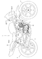
図1は、本実施の形態に係る内燃機関10を搭載した自動二輪車1の全体側面図である。
Hereinafter, an embodiment according to the present invention will be described with reference to FIGS.
FIG. 1 is an overall side view of a motorcycle 1 equipped with an
本自動二輪車1の車体フレーム2は、ヘッドパイプ2aから後方へ左右一対のメインフレーム2b,2bが延出した後に下方に屈曲して急傾斜部2ba,2baを形成し、その下部をくの字に前方に屈曲させて下端部に至っている。
またヘッドパイプ2aから斜め急角度に下方へ左右一対のダウンフレーム2c,2cが、側面視でメインフレーム2bの急傾斜部2baに略平行に延出している。
The
Further, a pair of left and right down frames 2c, 2c are extended substantially parallel to the steeply inclined portion 2ba of the main frame 2b in a side view when viewed downward from the
メインフレーム2b,2bの急傾斜部2ba,2baの上部からはシートレール2d,2dが後方に延出し、同シートレール2d,2dの中央部と急傾斜部2ba,2baの下部とを連結したバックステー2e,2eがシートレール2d,2dを支持している。 The seat rails 2d and 2d extend rearward from the upper portions of the steeply inclined portions 2ba and 2ba of the main frames 2b and 2b, and the back connecting the central portion of the seat rails 2d and 2d and the lower portion of the steeply inclined portions 2ba and 2ba. The stays 2e and 2e support the seat rails 2d and 2d.
以上のような車体フレーム2において、ヘッドパイプ2aにはフロントフォーク3が枢支され、その下端に前輪4が軸支され、メインフレーム2b,2bの下部に設けられたピボットプレート2fに前端を軸支されたリヤフォーク5が後方へ延出し、その後端に後輪6が軸支され、リヤフォーク5の後部とシートレール2d,2dの中央部との間にリヤクッション7が介装されている。
メインフレーム2b,2bには燃料タンク8が架設され、燃料タンク8の後方にシート9がシートレール2d,2dに支持されて設けられている。
In the
A fuel tank 8 is installed on the main frames 2b and 2b, and a seat 9 is provided behind the fuel tank 8 and supported by
車体フレーム2に搭載される内燃機関10は、SOHC型2バルブの単気筒4ストローク内燃機関であり、車体に対してクランク軸20を車体幅方向に指向させ、気筒を若干前傾させて起立した姿勢で懸架される。
The
内燃機関10のクランク軸12を回転自在に軸支するクランクケース11は、クランク軸12の後方に配設されるメイン軸13とカウンタ軸14の間に変速歯車機構15が構成されており、カウンタ軸14は出力軸であり、後輪6の回転軸との間にチェーン(図示せず)が架渡され動力が後輪6に伝達される。
A
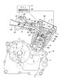
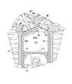
図2を参照して、クランクケース11の上には、1本の鋳鉄製のシリンダライナ16Lが鋳込まれたシリンダブロック16と、シリンダブロック16の上にガスケットを介してシリンダヘッド17が重ねられ、スタッドボルトにより一体に締結され、シリンダヘッド17の上方をシリンダヘッドカバー18が覆っている。
クランクケース11の上に重ねられるシリンダブロック16,シリンダヘッド17,シリンダヘッドカバー18は、クランクケース11から若干前傾した姿勢で上方に延出している(図1,図2参照)。
Referring to FIG. 2, a
The
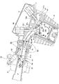
このように車体フレームに搭載された内燃機関10の若干前傾して立設されたシリンダヘッド16から後方に連結管19を介してインレットパイプ20が延出し、インレットパイプ20にはスロットル弁22を内蔵するバタフライ型のスロットルボディ21が設けられるとともに、インジェクタ23が装着され、さらに後記する吸気振分け弁61が設けられている。
In this way, the
このインレットパイプ20の後端に連結されるエアクリーナ24が側面視でメインフレーム2aとシートレール2dとバックステー2eに囲まれた空間に配設される(図1参照)。
また、シリンダヘッド13から前方に延出した排気管25は、下方に屈曲し、さらに後方に屈曲してクランクケース12の下面に沿って後方にかつ右側に寄って後輪6の右側に配置されたマフラー26に連結している。
An
Further, the
図2を参照して、クランクケース11は左右割りで、左右クランクケースの合せ面に形成された開口にシリンダライナ16Lの下端部が嵌入してシリンダブロック16が若干前傾して上方に突出しており、同シリンダライナ16Lの内部のシリンダボア16bにピストン25が往復摺動自在に嵌合され、ピストン25のピストンピン25pとクランク軸12のクランクピン12pとの間をコンロッド26が連接してクランク機構を構成している。
Referring to FIG. 2, the
シリンダブロック16のシリンダボア16b内を摺動するピストン25の頂面25tと同頂面25tが対向するシリンダヘッド17の天井面41との間に燃焼室40が構成される。
シリンダヘッド17には、天井面41にシリンダボア16bの中心軸であるシリンダ軸Cに関して互いに反対位置に1つずつ吸気弁口42と排気弁口43が燃焼室40に臨んで開口されるとともに、吸気弁口42と排気弁口43から各々吸気ポート44と排気ポート45が互いに離れる方向に湾曲しながら延出して形成されている。
A
In the
吸気ポート44は、吸気弁口42から後方に延出し、連結管19を介してインレットパイプ20に連通し、排気ポート45は排気管25に連結される。
シリンダヘッド16に一体に嵌着された弁ガイド34i,34eにそれぞれバルブステム46s,47sが摺動可能に支持された吸気弁46および排気弁47は、シリンダヘッド13の上に設けられる動弁装置30により駆動されて、吸気ポート44の吸気弁口42および排気ポート45の排気弁口43をクランク軸12の回転に同期して開閉される。
The
An
図2を参照して、本内燃機関10の動弁装置30は、吸気弁46と排気弁47のバルブステム46s,47sをプランジャとして進退させる吸気弁リフト量可変ソレノイド90と排気弁リフト量可変ソレノイド91がシリンダヘッド17の上に設けられている。
吸気弁リフト量可変ソレノイド90と排気弁リフト量可変ソレノイド91は電磁ソレノイドであり、吸気弁46と排気弁47のリフト量は印加電圧により調整することができる。
Referring to FIG. 2, a valve operating device 30 of the
The intake valve lift amount
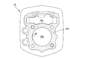
図3は、シリンダブロック16の上面図であり、シリンダヘッド17との合せ面16fにシリンダボア16bの円孔と動弁機構30に動力を伝達するチェーンを挿通するチェーン室16cの矩形孔が穿設されている。
図4は、シリンダブロック16に重ね合わされるシリンダヘッド17の下面図であり、シリンダブロック16に合せ面16fに対向する合せ面17fに、シリンダボア16bに対応して燃焼室40の天井面41が凹んで形成されるとともに、チェーン室16cに対応して連通するチェーン室17cが穿設されている。
FIG. 3 is a top view of the
FIG. 4 is a bottom view of the
シリンダヘッド17の合せ面17fにおける燃焼室40の天井面41の円形開口縁41sがシリンダボア16bの円孔に一致する。
天井面41の後側に大径の吸気弁口42が開口し、天井面41の前側に吸気弁口42より幾らか小径の排気弁口43が開口している。
また、天井面41には点火プラグ(図示せず)が先端を突出させるプラグ孔48が穿設されている。
A
A large-diameter
The
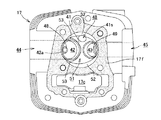
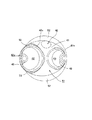
図5は、シリンダヘッド17の燃焼室40をシリンダ軸Cの軸方向に視た、すなわちシリンダ軸方向視で示した図であり、同図5を参照して、吸気弁口42が燃焼室40の天井面41のシリンダボア16bの円孔に対応する円形の天井面開口縁41sよりシリンダ軸方向視で外側にはみ出してオフセットしており、吸気弁口42は天井面開口縁41sからはみ出した三日月状のはみ出し部42a(図5の散点で示した部分)を有する。
FIG. 5 is a view of the
吸気弁口42の開口縁42sの開口全周長に対するはみ出し部42aの開口周長の割合をマスキング割合Rmとすると、本吸気弁口42のオフセットによるマスキング割合Rmは26%程度である。
When the ratio of the opening circumferential length of the protruding
また、図5を参照して、天井面41には、吸気弁口42と排気弁口43を長径方向両側に囲む楕円状の横断面形状を有してドーム状凹部51が形成されており、天井面41のうちドーム状凹部51の外側の左右1対の三日月状部分にそれぞれスキッシュ52,52が形成されている。
Referring to FIG. 5, the
そして、吸気弁口42の外周囲に、吸気弁口42の三日月状のはみ出し部42aの両端部辺りから吸気弁口42の開口縁42sに沿って湾曲した1対のガイド壁面53,53が、互いに対向して前記排気弁口43側に向けて徐々に拡開して形成されている。
A pair of guide wall surfaces 53, 53 curved around the opening
以上のように形成されたシリンダヘッド17の燃焼室40の天井面41に対して、シリンダブロック16のシリンダボア16bは、図3および図6に示すように、シリンダボア16bのシリンダヘッド17側の開口縁における吸気弁口42のはみ出し部42aに対向する後側部分を吸気弁46の移動方向に吸気弁46のかさ部46p周縁に沿ってシリンダボア16bまで切り欠いた切欠き円曲面55が形成されている。
With respect to the
図6に示すように、切欠き円曲面55は、鋳鉄製のシリンダライナ16Lが鋳込まれたアルミ合金製のシリンダブロック16のシリンダライナ16Lの端面を覆う部分に斜めに切り欠かれて形成されている。
As shown in FIG. 6, the cut circular
この切欠き円曲面55に沿って切欠き円曲面55に近接して吸気弁46のかさ部46p周縁が移動するので、吸気弁46が開いて最大バルブリフト位置まで移動する間、吸気弁口42の外側縁側(はみ出し部42a側)からの吸気は、吸気弁46のかさ部46p周縁と切欠き円曲面55との極めて狭い隙間を通らなければならず燃焼室40への吸入が殆ど妨げられマスキングされた状態にある。
Since the peripheral edge of the
したがって、吸気弁口42の外側縁側からはマスキングされて燃焼室40には僅かに吸入されるだけで、吸気弁口42の内側縁側からの吸入が主になり、よってタンブルが発生し易い構造となっている。
Therefore, it is masked from the outer edge side of the
なお、ピストン25の頂面25tの周縁部の吸気弁口42のはみ出し部42aに対向する部分が吸気弁46のかさ部46pの端面46pfと平行に切り欠かれてピストン切欠き面56が形成されており(図6参照)、吸気行程でピストン25の下降とともに吸気弁46が開弁しリフトするときに、ピストン切欠き面56と吸気弁46のかさ部46pの端面46pfとが平行に略間隔を維持して移動して負圧が生じ難いため、吸気弁口42の外側縁側から燃焼室40に吸気の吸入が促されることはなく、逆タンブルの発生がより抑えられている。
A portion of the peripheral surface of the
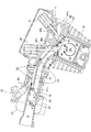
そして、吸気系において、インレットパイプ20から連結管19を介して吸気ポート44に至る吸気通路Pが、インレットパイプ20の下流部から吸気ポート44の湾曲部まで仕切板60により上側吸気通路Upと下側吸気通路Lpに仕切られている。
In the intake system, the intake passage P extending from the
仕切板60は、インレットパイプ20と一体に形成されており、仕切板60の上流端部がインレットパイプ20の内側に上下を仕切って設けられ、下流側に大きく飛び出した延出部分が吸気ポート44に挿入されている。
仕切板60の帯状の延出部分はその両側縁を吸気ポート44の内周面に沿って挿入される。
仕切板60は、吸気通路Pを上方に寄っており、上側吸気通路Upの通路断面積が下側吸気通路Lpの通路断面積より小さい。
The
The strip-like extended portion of the
The
仕切板60の長尺の延出部は、吸気ポート44の形状に沿って曲がっており、先端の下流端部60eは吸気ポート44の湾曲部に位置する吸気弁46の吸気バルブステム46sに達しており、仕切板60の下流端部60eは先端縁から凹んだ凹部60uが形成されていて、このU字状凹部60uを吸気バルブステム46sが貫通している(図6参照)。
The long extending portion of the
そして、下流端部60eは、湾曲していない平板状で吸気ポート44の湾曲部に直線的に挿入され、その下流端部60eの左右側部が吸気ポート44の湾曲部に左右に対向して形成された左右凹溝44v,44vに嵌入されて固定支持される(図6参照)。
The
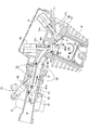
インレットパイプ20内において、スロットル弁22よりも下流で仕切板60の上流に吸気振分け弁61が設けられている。
図6,図7,図8を参照して、吸気振分け弁61は、基端の回動軸61aがインレットパイプ20に仕切板60の上流端縁の近傍で軸支されて吸気上流側に向けた先端を上下に揺動自在としたフラッグバルブであり、モータ駆動機構62により揺動させられる。
In the
Referring to FIGS. 6, 7, and 8, in the
吸気振分け弁61は、上流のスロットル弁22に先端を向けて揺動することで、スロットル弁22より下流の吸気を上下に振り分け上側吸気通路Upと下側吸気通路Lpを流れる吸気の割合を変更することができる。
The
内燃機関10を制御するECU(電子制御ユニット)65は、吸気制御手段66を備えており、内燃機関10の運転状態を解析して吸気制御手段66により吸気系のスロットル弁21やインジェクタ23が駆動制御されるが、吸気振分け弁61および前記吸気弁リフト量可変ソレノイド90も吸気制御手段66により駆動制御される。
なお、排気弁リフト量可変ソレノイド91もECU65により駆動制御される。
An ECU (electronic control unit) 65 that controls the
The exhaust valve
吸気制御手段66により制御されて吸気弁リフト量可変ソレノイド90により進退する吸気弁46の最大バルブリフト量Dとして、内燃機関10の負荷状態に応じて所定の最小値d1,中間値d2,最大値d3の3つの値を設定している。
The maximum valve lift amount D of the
図6には、3つの吸気弁46の最大バルブリフト位置を実線と2点鎖線で示している。
図6において、最大バルブリフト量Dが最小値d1である実線で示された吸気弁46の位置が、内燃機関10の低負荷状態における最大バルブリフト位置であり、最大バルブリフト量Dが中間値d2である2点鎖線で示された吸気弁46の位置が、内燃機関10の中負荷状態における最大バルブリフト位置であり、最大バルブリフト量Dが最大値d3である2点鎖線で示された吸気弁46の位置が、内燃機関10の高負荷状態における最大バルブリフト位置である。
In FIG. 6, the maximum valve lift positions of the three
In FIG. 6, the position of the
シリンダブロック16のシリンダボア16bのシリンダヘッド17側の開口縁に形成された切欠き円曲面55は、吸気弁46の閉弁位置から最大バルブリフト量Dが最小値d1を経て中間値d2まで吸気弁46のかさ部46pに近接して極めて狭い隙間を形成して、吸気の吸気弁口42の外側縁側(はみ出し部42a側)から燃焼室40への吸入は殆ど妨げられマスキングされる。
A notch circular
しかし、高負荷状態のときの吸気弁46の最大バルブリフト量Dが最大値d3の最大バルブリフト位置は、切欠き円曲面55を越えた位置にあり、よって吸気の吸気弁口42の外側縁側から燃焼室40への吸入はマスキングされず、容易に吸入されるので、タンブルと逆向きの所謂逆タンブルを発生しタンブルを抑制する。
However, the maximum valve lift position where the maximum valve lift amount D of the
図7を参照して、スロットル弁22のスロットル開度θは、全閉時から回動して吸気通路に平行になったときが全開状態であり、内燃機関10の負荷状態を示す。
吸気振分け弁61は、内燃機関10の負荷状態に応じて揺動制御され、吸気振分け弁61の揺動角である吸気振分け弁開度φは、図7に示す低負荷状態のときの吸気振分け弁61の低負荷位置を基準0度として図7で時計回りに揺動角度が増加する。
Referring to FIG. 7, the throttle opening θ of the
The
タンブルの状態は、クランク軸の1回転当りのタンブルの回転数であるタンブル比Rtで表わすことができる。
タンブル比Rt=タンブル回転角速度/クランク軸角速度
タンブル比Rtが大きければ、強い渦流がタンブルが発生している。
The tumble state can be expressed by a tumble ratio Rt which is the number of rotations of the tumble per rotation of the crankshaft.
Tumble ratio Rt = tumble rotation angular velocity / crankshaft angular velocity If the tumble ratio Rt is large, a strong vortex is tumbled.
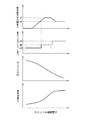
図10には、スロットル開度θに応じて吸気振分け弁61を揺動制御する吸気振分け弁開度φの制御と吸気弁46の最大バルブリフト量Dの制御とタンブル比Rtの変化および吸気流量Qの変化を示している。
以下、図10を参照しつつ、内燃機関10の負荷状態による吸気振分け弁61の揺動制御と吸気弁46の最大バルブリフト量制御とタンブル比Rtおよび吸気流量Qの変化を考察する。
FIG. 10 shows the control of the intake distribution valve opening φ for swinging the
Hereinafter, with reference to FIG. 10, changes in the swing control of the
内燃機関10が低負荷運転状態のときは、図7に示すように、スロットル弁21は小さく開いており(スロットル開度θ:小)、吸気振分け弁61は先端縁が吸気通路Pの下側周面に接した低負荷位置(吸気振分け弁開度φ=0度)に位置決めされているので、吸気振分け弁61は吸気を大部分上方に振り分けて上側吸気通路Upを流れ、吸気弁46の最大バルブリフト量を最小値d1としている。
最大バルブリフト量の最小値d1は、吸気弁46のかさ部46pが切欠き円曲面55に位置するリフト量であり、吸気弁口42から燃焼室40に入るところが狭くなってバルブ有効開口面積が小さく、吸気弁口42の外側縁側はマスキングされた状態にある。
When the
The minimum value d1 of the maximum valve lift amount is a lift amount at which the
したがって、吸気流量Qは小さい。
そして、スロットル弁21の僅かに開いた開口を通った吸気は、大部分吸気振分け弁61により大部分上方の比較的狭い上側吸気通路Upに案内され流れるために高速となり、さらに吸気ポート44の湾曲部に位置する吸気バルブステム46sまで延出した仕切板60により吸気弁口42の近くまで案内され、大部分の吸気が吸気弁口42の内側縁側(シリンダ軸C側)から絞られてより高速になって燃焼室40に吸入されることになり、図7に示すように、強い渦流のタンブルが発生する(タンブル比Rtが上昇)。
Therefore, the intake flow rate Q is small.
The intake air that has passed through the slightly opened opening of the
吸気弁口42がシリンダボア16bの円孔よりシリンダ軸方向視で外側にはみ出した三日月状のはみ出し部42aを有するようにオフセットして、吸気弁口42の外側縁側(はみ出し部42a側)はマスキングされ、かつ下側吸気通路Lpを通る吸気は殆どないため、吸気弁口42の外側縁側から燃焼室40に吸入する吸気はなく、タンブルを妨げる逆タンブルも発生せず、タンブルをより強く発生させ、タンブル比Rtは高くなり、低負荷時の燃焼効率を向上させることができる。
The
内燃機関10が中負荷運転状態のときは、図8に示すように、スロットル弁21は中開度に開き(スロットル開度θ:中)、吸気振分け弁61は先端縁が吸気通路Pの上側周面に近づいた中負荷位置(吸気振分け弁開度φ=β度)に位置決めされているので、吸気振分け弁61は吸気を下方より上方の割合を小さく振り分けている。
したがって、図8に矢印で示すように、下側吸気通路Lpは十分な吸気が流れるが、上側吸気通路Upを流れる吸気は抑制される。
そして、吸気弁46の最大バルブリフト量は、吸気弁46のかさ部46pが切欠き円曲面55の下端に位置する中間値d2に設定され、吸気弁46の最大バルブリフト量を中間値d2としてバルブ有効開口面積が大きくなるが、吸気弁口42の外側縁側はなおもマスキングされた状態にある。
When the
Therefore, as indicated by an arrow in FIG. 8, sufficient intake air flows through the lower intake passage Lp, but intake air flowing through the upper intake passage Up is suppressed.
Then, the maximum valve lift amount of the
そのため、上側吸気通路Upを流れる抑制された吸気は、吸気弁口42の内側縁側から燃焼室40に入っても、弱い渦流のタンブルしか発生しないが、吸気弁口42の外側縁側から燃焼室40に吸入される吸気はマスキングされて逆タンブルは生じ難いため、適度に抑えられたタンブルを発生し、強過ぎるタンブルによる急速燃焼のため燃費が増加するのを防止できるとともに、急速燃焼を原因としたクランク打音の発生も防止できる。
Therefore, even if the suppressed intake air flowing through the upper intake passage Up enters the
内燃機関10が高負荷運転状態のときは、図9に示すように、スロットル弁21は全開となり(スロットル開度θ:全開)、吸気振分け弁61は仕切板60と同一平面をなす高負荷位置(吸気振分け弁開度φ=α度)に位置決めされているので、吸気振分け弁61は吸気を仕切板(60)に仕切られた割合に吸気を上下に振り分けている。
そして、吸気弁46の最大バルブリフト量を最大値d3としてバルブ有効開口面積がさらに大きくなり、吸気弁46のかさ部46pは切欠き円曲面55を越えて吸気弁口42の外側縁側のマスキングは解除される。
When the
The maximum valve lift amount of the
したがって、吸気流量Qは大きい。
そして、図9に矢印で示すように、上側吸気通路Upと下側吸気通路Lpを十分な吸気が流れ、上側吸気通路Upを流れた吸気は、吸気弁口42の内側縁側から燃焼室40に吸入されてタンブルを発生するが、下側吸気通路Lpを流れた吸気は、マスキングが解除され、吸気弁口42の外側縁側から燃焼室40に入って逆タンブルを生じ、タンブルは抑制される。
しかし上側吸気通路Upと下側吸気通路Lpから十分な吸気量が吸入され、吸気効率は良好である。
Therefore, the intake flow rate Q is large.
As shown by arrows in FIG. 9, sufficient intake air flows through the upper intake passage Up and the lower intake passage Lp, and the intake air that flows through the upper intake passage Up enters the
However, a sufficient intake amount is drawn from the upper intake passage Up and the lower intake passage Lp, and the intake efficiency is good.
以上のように、本内燃機関10の吸気装置は、内燃機関の負荷状態に応じて吸気振分け弁61による吸気の上下の振分け割合と吸気弁46の最大バルブリフト量とを変えて、タンブルの渦流の強さを調整して燃焼効率の最適化を図ることができる。
As described above, the intake device of the
なお、内燃機関10が中負荷状態から高負荷状態に移る際に、吸気振分け弁61を中負荷位置(吸気振分け弁開度φ=β度)から高負荷位置(吸気振分け弁開度φ=α度)に揺動するが、揺動直後に上側吸気通路Upを流れる吸気が一気に増え、そのため吸気弁口42の内側縁側から燃焼室40に入る高速の吸気の増加により強いタンブルが発生することがあり、強過ぎるタンブルによる急速燃焼のおそれがある。
When the
そこで、内燃機関10が中負荷状態から高負荷状態に移る際は、図10の最大バルブリフト量の制御グラフにおいて破線で示すように、吸気弁46の最大バルブリフト量を中間値d2から一度小さく落として、有効開口面積を小さく抑えてタンブルを抑制し、その後最大バルブリフト量を大きくして最大値d3にすることで、急速燃焼を防止し、燃焼効率の最適化を推進することができる。
Therefore, when the
以上の実施の形態では、吸気弁46の最大バルブリフト量を変える吸気バルブリフト量可変機構として吸気弁リフト量可変ソレノイドを用いたが、クランク軸に連動するカム軸の回動により吸気弁が駆動される機械的な動弁カム機構において、カム軸と吸気弁との間に例えば圧力制御可能な油圧室を仲介させるなど、吸気弁の最大バルブリフト量を可変とする機構を用いてもよい。
In the above embodiment, the intake valve lift amount variable solenoid is used as the intake valve lift amount variable mechanism for changing the maximum valve lift amount of the
1…自動二輪車、2…車体フレーム、10…内燃機関、11…クランクケース、12…クランク軸、13…メイン軸、14…カウンタ軸、15…クランクケース、16…シリンダブロック、16b…シリンダボア、17…シリンダヘッド、18…シリンダヘッドカバー、19…連結管、
20…インレットパイプ、21…スロットルボディ、22…スロットル弁、23…インジェクタ、24…エアクリーナ、25…ピストン、26…コンロッド、34i,34e…弁ガイド、
40…燃焼室、41…天井面、42…吸気弁口、42a…はみ出し部、43…排気弁口、44…吸気ポート、45…排気ポート、46…吸気弁、46p…かさ部、46pf…端面、46s…吸気バルブステム、47…排気弁、48…プラグ孔、
51…ドーム状凹部、52…スキッシュ、53…ガイド壁面、54…、55…切欠き円曲面、56…ピストン切欠き面、
60…仕切板、61…吸気振分け弁、62…モータ駆動機構、65…ECU、66…吸気制御手段、
90…吸気弁リフト量可変ソレノイド、91…排気弁リフト量可変ソレノイド。
DESCRIPTION OF SYMBOLS 1 ... Motorcycle, 2 ... Body frame, 10 ... Internal combustion engine, 11 ... Crankcase, 12 ... Crankshaft, 13 ... Main shaft, 14 ... Countershaft, 15 ... Crankcase, 16 ... Cylinder block, 16b ... Cylinder bore, 17 ... Cylinder head, 18 ... Cylinder head cover, 19 ... Connecting pipe,
20 ... Inlet pipe, 21 ... Throttle body, 22 ... Throttle valve, 23 ... Injector, 24 ... Air cleaner, 25 ... Piston, 26 ... Connecting rod, 34i, 34e ... Valve guide,
40 ... Combustion chamber, 41 ... Ceiling surface, 42 ... Intake valve port, 42a ... Projection part, 43 ... Exhaust valve port, 44 ... Intake port, 45 ... Exhaust port, 46 ... Intake valve, 46p ... Bulk part, 46pf ... End face , 46s ... Intake valve stem, 47 ... Exhaust valve, 48 ... Plug hole,
51 ... Dome-shaped recess, 52 ... Squish, 53 ... Guide wall surface, 54 ..., 55 ... Notched circular curved surface, 56 ... Piston notched surface,
60 ... partition plate, 61 ... intake air distribution valve, 62 ... motor drive mechanism, 65 ... ECU, 66 ... intake control means,
90… Valve lift variable solenoid, 91… Valve lift variable solenoid.
Claims (4)
前記シリンダヘッド(17)の前記天井面(41)に開口した吸気弁口(42)と排気弁口(43)から各々吸気ポート(44)と排気ポート(45)が互いに離れる方向に湾曲しながら延出して形成され、
吸気ポート(44)にインレットパイプ(20)が接続されて連続した吸気通路(P)が構成され、
前記インレットパイプ(20)にスロットル弁(22)が設けられ、
前記吸気通路(P)が部分的に仕切板(60)により上側吸気通路(Up)と下側吸気通路(Lp)に仕切られ、
前記スロットル弁(22)よりも下流で前記仕切板(60)の上流に設けられた吸気振分け弁(61)により前記上側吸気通路(Up)と前記下側吸気通路(Lp)を流れる吸気が制御される内燃機関の吸気装置において、
前記吸気振分け弁(61)は、基端が前記インレットパイプに前記仕切板(60)の上流端縁の近傍で軸支されて吸気上流側に向けた先端を上下に揺動自在とし、
前記吸気弁口(42)を開閉する吸気弁(46)の最大バルブリフト量を変更する吸気バルブリフト量可変機構(90)と、
内燃機関の負荷状態に応じて前記吸気振分け弁(61)と前記吸気バルブリフト量可変機構(90)を駆動制御する吸気制御手段(66)とを備え、
前記吸気制御手段(66)は、
内燃機関が低負荷状態のときは、吸気を大部分上方に振り分けて前記上側吸気通路(Up)を流れるように前記吸気振分け弁(61)を位置決めするとともに、前記吸気バルブリフト量可変機構(90)を駆動して吸気弁(46)の最大バルブリフト量(D)を最小値(d1)に設定し、
内燃機関が中負荷状態のときは、吸気を下方より上方の割合を小さく振り分けて前記上側吸気通路(Up)を流れる吸気を抑制するように前記吸気振分け弁(61)を位置決めするとともに、前記吸気バルブリフト量可変機構(90)を駆動して吸気弁(46)の最大バルブリフト量(D)を中間値(d2)に設定し、
内燃機関が高負荷状態のときは、前記仕切板(60)に仕切られた割合に吸気を上下に振り分けるように前記吸気振分け弁(61)を位置決めするとともに、前記吸気バルブリフト量可変機構(90)を駆動して吸気弁(46)の最大バルブリフト量(D)を最大値(d3)に設定することを特徴とする内燃機関の吸気装置。 Combustion between the top surface of the piston (25) slidably fitted in the cylinder bore (16b) of the cylinder block (16) and the ceiling surface (41) of the cylinder head (17) facing the top surface Chamber (40) is constructed,
While the intake port (44) and the exhaust port (45) are curved away from each other from the intake valve port (42) and the exhaust valve port (43) opened in the ceiling surface (41) of the cylinder head (17). Formed to extend,
An inlet pipe (20) is connected to the intake port (44) to form a continuous intake passage (P),
The inlet pipe (20) is provided with a throttle valve (22),
The intake passage (P) is partially partitioned into an upper intake passage (Up) and a lower intake passage (Lp) by a partition plate (60),
The intake air distribution valve (61) provided downstream of the throttle valve (22) and upstream of the partition plate (60) controls intake air flowing through the upper intake passage (Up) and the lower intake passage (Lp). In an internal combustion engine intake device,
The intake divergence valve (61) has a base end pivotally supported by the inlet pipe in the vicinity of the upstream end edge of the partition plate (60), and a tip end toward the intake upstream side is swingable up and down.
An intake valve lift variable mechanism (90) for changing the maximum valve lift of the intake valve (46) for opening and closing the intake valve port (42);
Intake control means (66) for driving and controlling the intake valve (61) and the intake valve lift variable mechanism (90) according to the load state of the internal combustion engine,
The intake control means (66)
When the internal combustion engine is in a low load state, the intake valve (61) is positioned so that the intake air is largely distributed upward and flows through the upper intake passage (Up), and the intake valve lift amount variable mechanism (90 ) To set the maximum valve lift (D) of the intake valve (46) to the minimum value (d1),
When the internal combustion engine is in a medium load state, the intake air distribution valve (61) is positioned so as to suppress the intake air flowing through the upper intake passage (Up) by distributing the intake air from a lower upper portion to a lower proportion, and the intake air Drive the valve lift variable mechanism (90) to set the maximum valve lift (D) of the intake valve (46) to the intermediate value (d2).
When the internal combustion engine is in a high load state, the intake distribution valve (61) is positioned so as to distribute intake air up and down in proportion to the partition plate (60), and the intake valve lift amount variable mechanism (90 ) To set the maximum valve lift (D) of the intake valve (46) to the maximum value (d3) .
内燃機関が中負荷状態から高負荷状態に移行するときは、吸気を下方より上方の割合を小さく振り分ける中負荷位置に位置決めされた前記吸気振分け弁(61)を仕切板に仕切られた割合に吸気を上下に振り分ける高負荷位置に駆動すると同時に、前記吸気バルブリフト量可変機構(90)を駆動して吸気弁(46)の最大バルブリフト量(D)を中間値(d2)から一度小さくしてから再び大きくして最大値(d3)に設定することを特徴とする請求項1記載の内燃機関の吸気装置。 The intake control means (66)
When the internal combustion engine transitions from a medium load state to a high load state, the intake valve (61), which is positioned at a medium load position that distributes the intake air from a lower portion to a lower portion, is taken into the intake air at a rate partitioned by a partition plate. Is driven to a high load position that distributes the valve vertically, and at the same time, the maximum valve lift amount (D) of the intake valve (46) is reduced once from the intermediate value (d2) by driving the intake valve lift variable mechanism (90). 2. The intake device for an internal combustion engine according to claim 1, wherein the value is increased again to a maximum value (d3).
前記吸気弁口(42)がシリンダボア(16b)の円孔よりシリンダ軸方向視で外側にはみ出した三日月状のはみ出し部(42a)を有するようにオフセットして形成され、
前記シリンダブロック(16)のシリンダボア(16b)のシリンダヘッド(17)側の開口縁における前記吸気弁口のはみ出し部(42a)に対向する部分を吸気弁(46)の移動方向に前記吸気弁(46)のかさ部周縁に沿って吸気弁(46)の最大バルブリフト量(D)の前記中間値(d2)まで切り欠いてシリンダボア(16b)の内周面に至る切欠き円曲面(55)が形成されることを特徴とする請求項1または請求項2記載の内燃機関の吸気装置。 The intake valve port (42) and the exhaust valve port (43) are arranged on the ceiling surface (41) of the cylinder head (17) one at a position opposite to each other with respect to the cylinder axis (C) which is the central axis of the cylinder bore (16b). ) Is opened facing the combustion chamber (40),
The intake valve port (42) is offset and formed so as to have a crescent-shaped protrusion (42a) protruding outward from the circular hole of the cylinder bore (16b) in the cylinder axial direction.
A portion of the opening of the cylinder block (16) on the cylinder head (17) side of the cylinder bore (16b) facing the protruding portion (42a) of the intake valve port in the moving direction of the intake valve (46) A notched circular curved surface (55) that cuts up to the intermediate value (d2) of the maximum valve lift amount (D) of the intake valve (46) along the periphery of the beveled portion of 46) and reaches the inner peripheral surface of the cylinder bore (16b) An intake device for an internal combustion engine according to claim 1 or 2 , characterized in that is formed.
Priority Applications (1)
| Application Number | Priority Date | Filing Date | Title |
|---|---|---|---|
| JP2012080063A JP5908321B2 (en) | 2012-03-30 | 2012-03-30 | Internal combustion engine |
Applications Claiming Priority (1)
| Application Number | Priority Date | Filing Date | Title |
|---|---|---|---|
| JP2012080063A JP5908321B2 (en) | 2012-03-30 | 2012-03-30 | Internal combustion engine |
Publications (2)
| Publication Number | Publication Date |
|---|---|
| JP2013209914A JP2013209914A (en) | 2013-10-10 |
| JP5908321B2 true JP5908321B2 (en) | 2016-04-26 |
Family
ID=49527966
Family Applications (1)
| Application Number | Title | Priority Date | Filing Date |
|---|---|---|---|
| JP2012080063A Expired - Fee Related JP5908321B2 (en) | 2012-03-30 | 2012-03-30 | Internal combustion engine |
Country Status (1)
| Country | Link |
|---|---|
| JP (1) | JP5908321B2 (en) |
Families Citing this family (1)
| Publication number | Priority date | Publication date | Assignee | Title |
|---|---|---|---|---|
| JP2021175876A (en) * | 2018-07-12 | 2021-11-04 | ヤマハ発動機株式会社 | Spark-ignition engine and vehicle |
Family Cites Families (6)
| Publication number | Priority date | Publication date | Assignee | Title |
|---|---|---|---|---|
| JP2001003755A (en) * | 1999-06-21 | 2001-01-09 | Hitachi Ltd | In-cylinder air flow generation method for internal combustion engines |
| JP3840871B2 (en) * | 2000-03-14 | 2006-11-01 | 日産自動車株式会社 | Compression self-ignition gasoline engine |
| JP4192633B2 (en) * | 2003-03-03 | 2008-12-10 | 日産自動車株式会社 | Direct-injection spark ignition internal combustion engine |
| JP4728195B2 (en) * | 2006-09-20 | 2011-07-20 | ヤマハ発動機株式会社 | Engine intake control device |
| JP2008215126A (en) * | 2007-03-01 | 2008-09-18 | Nissan Motor Co Ltd | Internal combustion engine |
| JP4850853B2 (en) * | 2008-01-15 | 2012-01-11 | 富士重工業株式会社 | Engine intake control device |
-
2012
- 2012-03-30 JP JP2012080063A patent/JP5908321B2/en not_active Expired - Fee Related
Also Published As
| Publication number | Publication date |
|---|---|
| JP2013209914A (en) | 2013-10-10 |
Similar Documents
| Publication | Publication Date | Title |
|---|---|---|
| JP5925878B2 (en) | Intake device for internal combustion engine | |
| JP6000785B2 (en) | Intake device for internal combustion engine | |
| US7802555B2 (en) | Intake control device for an engine | |
| JP5145133B2 (en) | General-purpose engine exhaust gas recirculation structure | |
| JP5894520B2 (en) | Internal combustion engine | |
| JP5908321B2 (en) | Internal combustion engine | |
| JP5841985B2 (en) | Combustion chamber structure of internal combustion engine | |
| CN103362634B (en) | Internal-combustion engine | |
| JP2013213409A (en) | Intake device for internal combustion engine | |
| JP6005465B2 (en) | Intake device for internal combustion engine | |
| JP2016070206A (en) | Intake device for internal combustion engine | |
| JP2013072390A (en) | Internal combustion engine | |
| JP2013194585A (en) | Intake port of internal combustion engine | |
| JP4712844B2 (en) | Combustion chamber structure of internal combustion engine | |
| JP6241988B2 (en) | Internal combustion engine | |
| JP5347486B2 (en) | Variable intake system for internal combustion engine | |
| JP3320775B2 (en) | Engine intake control device | |
| JPH0666148A (en) | Intake controller for engine | |
| JP2887877B2 (en) | Engine intake control device | |
| JPH0740656Y2 (en) | Exhaust control device for 2-cycle engine | |
| JP2003120346A (en) | Intake device for four-stroke internal combustion engine | |
| JP4711141B2 (en) | Intake device | |
| JP2004339972A (en) | Intake control device for internal combustion engine | |
| JPH051549A (en) | Engine intake controller | |
| JP2008106641A (en) | Throttle valve device |
Legal Events
| Date | Code | Title | Description |
|---|---|---|---|
| A621 | Written request for application examination |
Free format text: JAPANESE INTERMEDIATE CODE: A621 Effective date: 20141127 |
|
| A977 | Report on retrieval |
Free format text: JAPANESE INTERMEDIATE CODE: A971007 Effective date: 20150831 |
|
| A131 | Notification of reasons for refusal |
Free format text: JAPANESE INTERMEDIATE CODE: A131 Effective date: 20150901 |
|
| A521 | Request for written amendment filed |
Free format text: JAPANESE INTERMEDIATE CODE: A523 Effective date: 20150928 |
|
| TRDD | Decision of grant or rejection written | ||
| A01 | Written decision to grant a patent or to grant a registration (utility model) |
Free format text: JAPANESE INTERMEDIATE CODE: A01 Effective date: 20160301 |
|
| A61 | First payment of annual fees (during grant procedure) |
Free format text: JAPANESE INTERMEDIATE CODE: A61 Effective date: 20160323 |
|
| R150 | Certificate of patent or registration of utility model |
Ref document number: 5908321 Country of ref document: JP Free format text: JAPANESE INTERMEDIATE CODE: R150 |
|
| LAPS | Cancellation because of no payment of annual fees |