RU2626028C2 - Street navigation system using infrastructure elements - Google Patents
Street navigation system using infrastructure elements Download PDFInfo
- Publication number
- RU2626028C2 RU2626028C2 RU2014148546A RU2014148546A RU2626028C2 RU 2626028 C2 RU2626028 C2 RU 2626028C2 RU 2014148546 A RU2014148546 A RU 2014148546A RU 2014148546 A RU2014148546 A RU 2014148546A RU 2626028 C2 RU2626028 C2 RU 2626028C2
- Authority
- RU
- Russia
- Prior art keywords
- infrastructure
- elements
- route
- remote location
- infrastructure elements
- Prior art date
Links
Images

Classifications
-
- H—ELECTRICITY
- H05—ELECTRIC TECHNIQUES NOT OTHERWISE PROVIDED FOR
- H05B—ELECTRIC HEATING; ELECTRIC LIGHT SOURCES NOT OTHERWISE PROVIDED FOR; CIRCUIT ARRANGEMENTS FOR ELECTRIC LIGHT SOURCES, IN GENERAL
- H05B47/00—Circuit arrangements for operating light sources in general, i.e. where the type of light source is not relevant
- H05B47/10—Controlling the light source
- H05B47/175—Controlling the light source by remote control
- H05B47/19—Controlling the light source by remote control via wireless transmission
-
- G—PHYSICS
- G08—SIGNALLING
- G08B—SIGNALLING OR CALLING SYSTEMS; ORDER TELEGRAPHS; ALARM SYSTEMS
- G08B7/00—Signalling systems according to more than one of groups G08B3/00 - G08B6/00; Personal calling systems according to more than one of groups G08B3/00 - G08B6/00
- G08B7/06—Signalling systems according to more than one of groups G08B3/00 - G08B6/00; Personal calling systems according to more than one of groups G08B3/00 - G08B6/00 using electric transmission, e.g. involving audible and visible signalling through the use of sound and light sources
- G08B7/066—Signalling systems according to more than one of groups G08B3/00 - G08B6/00; Personal calling systems according to more than one of groups G08B3/00 - G08B6/00 using electric transmission, e.g. involving audible and visible signalling through the use of sound and light sources guiding along a path, e.g. evacuation path lighting strip
-
- G—PHYSICS
- G01—MEASURING; TESTING
- G01C—MEASURING DISTANCES, LEVELS OR BEARINGS; SURVEYING; NAVIGATION; GYROSCOPIC INSTRUMENTS; PHOTOGRAMMETRY OR VIDEOGRAMMETRY
- G01C21/00—Navigation; Navigational instruments not provided for in groups G01C1/00 - G01C19/00
- G01C21/20—Instruments for performing navigational calculations
- G01C21/206—Instruments for performing navigational calculations specially adapted for indoor navigation
-
- G—PHYSICS
- G01—MEASURING; TESTING
- G01C—MEASURING DISTANCES, LEVELS OR BEARINGS; SURVEYING; NAVIGATION; GYROSCOPIC INSTRUMENTS; PHOTOGRAMMETRY OR VIDEOGRAMMETRY
- G01C21/00—Navigation; Navigational instruments not provided for in groups G01C1/00 - G01C19/00
- G01C21/26—Navigation; Navigational instruments not provided for in groups G01C1/00 - G01C19/00 specially adapted for navigation in a road network
- G01C21/34—Route searching; Route guidance
- G01C21/36—Input/output arrangements for on-board computers
- G01C21/3626—Details of the output of route guidance instructions
-
- G—PHYSICS
- G01—MEASURING; TESTING
- G01S—RADIO DIRECTION-FINDING; RADIO NAVIGATION; DETERMINING DISTANCE OR VELOCITY BY USE OF RADIO WAVES; LOCATING OR PRESENCE-DETECTING BY USE OF THE REFLECTION OR RERADIATION OF RADIO WAVES; ANALOGOUS ARRANGEMENTS USING OTHER WAVES
- G01S19/00—Satellite radio beacon positioning systems; Determining position, velocity or attitude using signals transmitted by such systems
- G01S19/01—Satellite radio beacon positioning systems transmitting time-stamped messages, e.g. GPS [Global Positioning System], GLONASS [Global Orbiting Navigation Satellite System] or GALILEO
- G01S19/13—Receivers
-
- H—ELECTRICITY
- H05—ELECTRIC TECHNIQUES NOT OTHERWISE PROVIDED FOR
- H05B—ELECTRIC HEATING; ELECTRIC LIGHT SOURCES NOT OTHERWISE PROVIDED FOR; CIRCUIT ARRANGEMENTS FOR ELECTRIC LIGHT SOURCES, IN GENERAL
- H05B45/00—Circuit arrangements for operating light-emitting diodes [LED]
- H05B45/20—Controlling the colour of the light
-
- H—ELECTRICITY
- H05—ELECTRIC TECHNIQUES NOT OTHERWISE PROVIDED FOR
- H05B—ELECTRIC HEATING; ELECTRIC LIGHT SOURCES NOT OTHERWISE PROVIDED FOR; CIRCUIT ARRANGEMENTS FOR ELECTRIC LIGHT SOURCES, IN GENERAL
- H05B47/00—Circuit arrangements for operating light sources in general, i.e. where the type of light source is not relevant
- H05B47/10—Controlling the light source
- H05B47/105—Controlling the light source in response to determined parameters
Landscapes
- Engineering & Computer Science (AREA)
- Radar, Positioning & Navigation (AREA)
- Remote Sensing (AREA)
- Physics & Mathematics (AREA)
- General Physics & Mathematics (AREA)
- Automation & Control Theory (AREA)
- Computer Networks & Wireless Communication (AREA)
- Navigation (AREA)
- Circuit Arrangement For Electric Light Sources In General (AREA)
- Audible And Visible Signals (AREA)
Abstract
Description
Эта заявка относится к области навигационных систем, а более конкретно к системе для обеспечения интуитивно понятных инструкций для направления пользователей к желаемым ими местам назначения.This application relates to the field of navigation systems, and more specifically to a system for providing intuitive instructions for directing users to their desired destinations.
Уличные карты и обращение с вопросом о пути являлись обычными средствами навигации по городским улицам. Обычно, когда пользователь хочет добраться до желаемого местоположения в новом городе, пользователь покупает карту и начинает идти или ехать до желаемого места назначения, изучая подробности карты. Когда пользователь (например, пешеходы, велосипедисты и другие медленно движущиеся пользователи) приближается к желаемому месту назначения, пользователь может остановиться и задать вопросы людям на улице.Street maps and addressing the question of the way were the usual means of navigating the city streets. Usually, when a user wants to get to a desired location in a new city, the user buys a map and starts walking or driving to the desired destination, studying the map details. When a user (for example, pedestrians, cyclists, and other slow moving users) approaches the desired destination, the user can stop and ask questions to people on the street.
С объединением технологии сотовой телефонной системы и технологии системы спутникового глобального позиционирования (GPS) пользователь может с удобством направляться к желаемому местоположению без необходимости покупать карты или спрашивать у прохожих направления. Однако степень точности технологии может вынуждать пользователя по-прежнему спрашивать направления.With the combination of cellular telephone technology and satellite global positioning system (GPS) technology, the user can conveniently go to their desired location without having to buy maps or ask directions from passers-by. However, the degree of accuracy of the technology may force the user to still ask for directions.
Кроме того, в случае чрезвычайных обстоятельств, и когда представители органов государственной власти хотят эвакуировать людей из одной или более областей, представителям органов государственной власти может потребоваться обеспечение инструкций относительно направления людям для обеспечения наиболее быстрых, наиболее безопасных и прямых инструкций для удаления людей из области.In addition, in case of emergency, and when government officials want to evacuate people from one or more areas, government officials may need to provide instructions on how to send people to provide the fastest, safest and most direct instructions for removing people from the area.
Следовательно, существует потребность в эффективной направляющей навигационной системе, которая может с удобством применяться пользователями для получения указаний на желаемые местоположения и которая может использоваться представителями местной государственной власти для обеспечения указаний по эвакуации людей в области, в которой случилось чрезвычайное происшествие.Therefore, there is a need for an effective guiding navigation system that can be conveniently used by users to obtain directions to their desired locations and which can be used by local government officials to provide directions for evacuating people in the area in which the emergency occurred.
Описана система для обеспечения информации о направлении, причем система содержит множество инфраструктурных элементов, размещенных по меньшей мере в одной сетевой конфигурации, инфраструктурные элементы имеют по меньшей мере одно из физического идентификатора местоположения и идентификатора данных, интерфейс, соединенный с каждым из множества инфраструктурных элементов, интерфейс включает в себя по меньшей мер одно из средства ввода и средства визуального вывода, центрального контроллера, связанного с инфраструктурными элементами, причем центральный контроллер реагирует на ввод, принятый от устройства ввода, ассоциированного с одним из упомянутого множества инфраструктурных элементов, касающиеся удаленного местоположения, назначает визуальный указатель принимаемому вводу, определяет маршрут из выбранных элементов из множества инфраструктурных элементов между положением, ассоциированным с устройством ввода, обеспечивающим принятый ввод, и инфраструктурным элементом, ближайшим к удаленному местоположению, при этом выбранные элементы из множества инфраструктурных элементов, как правило, являются соседними; и обеспечивает назначенный визуальный указатель последовательно каждому из выбранных элементов из упомянутого множества инфраструктурных элементов на маршруте в заданное время в течение определенного периода.A system for providing direction information is described, the system comprising a plurality of infrastructure elements located in at least one network configuration, infrastructure elements having at least one of a physical location identifier and a data identifier, an interface connected to each of the plurality of infrastructure elements, an interface includes at least one of the input means and means of visual output, a central controller associated with infrastructure elements wherein the central controller responds to input received from an input device associated with one of the plurality of infrastructure elements regarding a remote location, assigns a visual pointer to the input received, determines a route from selected elements from a plurality of infrastructure elements between a position associated with an input device providing received input, and the infrastructural element closest to the remote location, with selected elements from multiple infrastructures masonry elements are usually adjacent; and provides an assigned visual pointer sequentially to each of the selected elements from the aforementioned set of infrastructure elements along the route at a given time for a certain period.
Преимущества, сущность и различные дополнительные признаки изобретения станут более понятными после рассмотрения иллюстративных вариантов осуществления, которые описаны подробно в связи с сопровождающими чертежами, при этом аналогичные ссылочные позиции используются, чтобы идентифицировать аналогичный элемент на всех чертежах: Advantages, the nature and various additional features of the invention will become more apparent after consideration of illustrative embodiments, which are described in detail in connection with the accompanying drawings, with the same reference position used to identify a similar element in all the drawings:
Фиг. 1 представляет общегородскую сеть в соответствии с принципами изобретения;FIG. 1 represents a citywide network in accordance with the principles of the invention;
Фиг. 2 представляет сетевую конфигурацию в соответствии с принципами изобретения;FIG. 2 represents a network configuration in accordance with the principles of the invention;
Фиг. 3 представляет примерный интерфейс в соответствии с принципами изобретения;FIG. 3 represents an exemplary interface in accordance with the principles of the invention;
Фиг. 4 представляет способ обеспечения указания в соответствии с принципами изобретения;FIG. 4 represents a method for providing guidance in accordance with the principles of the invention;
Фиг. 5A представляет блок-схему способа работы системы, показанной на фиг. 1; иFIG. 5A is a flowchart of a method of operating the system shown in FIG. one; and
Фиг. 5B представляет блок-схему процесса обработки, выполняемой на каждом столбе системы, показанной на фиг. 1.FIG. 5B is a flowchart of the processing performed on each column of the system shown in FIG. one.
Следует понимать, что чертежи и описание настоящего изобретения, приведенные в данном документе, были упрощены, чтобы иллюстрировать элементы, которые являются актуальными для ясного понимания настоящего изобретения, при этом устраняя, в целях ясности, многие другие элементы. Однако, поскольку эти элементы хорошо известны в области техники, и/или поскольку они не способствуют лучшему пониманию настоящего изобретения, описание таких элементов не предусматривается в данном документе. Раскрытие в данном документе направлено также на вариации и модификации, известные специалистам в области техники.It should be understood that the drawings and description of the present invention provided herein have been simplified to illustrate elements that are relevant for a clear understanding of the present invention, while eliminating, for purposes of clarity, many other elements. However, since these elements are well known in the art, and / or since they do not contribute to a better understanding of the present invention, a description of such elements is not provided herein. The disclosure herein is also directed to variations and modifications known to those skilled in the art.
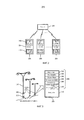
Фиг. 1 представляет примерную систему 100 общегородской сети, содержащую по меньшей мере один центральный компьютер 130 (только один иллюстрируется в целях ясности), который связан с множеством элементов 110 датчиков и/или осветительных элементов 140, которые взаимосвязаны в распределительной сети.FIG. 1 represents an example
Элементы 110 датчиков, например дымовой датчик, датчик качества воздуха, пожарный датчик, датчик изображения и т.д., устанавливаются в местах, чтобы обнаруживать различные чрезвычайные происшествия и формировать сигнал, который может быть отправлен центральному контроллеру 130 для анализа и правильной реакции.
Кроме того, по меньшей мере один центральный компьютер 130 может быть связан с городской системой 120 управления, которая обеспечивает централизованный контроль над общегородским управлением. Каждый из по меньшей мере одного центрального контроллера 130 может обеспечивать информацию городскому центру управления, касающуюся, например, дорожного движения, погоды, аварий, чрезвычайных происшествий и т.д. Городской центр 120 управления может обеспечивать информацию, касающуюся информации о большом чрезвычайном происшествии (например, землетрясении), центральному контроллеру 130. В ответ, центральный контроллер 130 будет выбирать один или множество маршрутов эвакуации и управлять множеством потолочных светильников или множеством дорожных фонарей, чтобы обеспечивать информацию о спасении и эвакуации, как будет описано более полно в данном документе.In addition, at least one
Центральный контроллер 130 может также быть связан с множеством уличных фонарей 150 или другими аналогичными инфраструктурными элементами (например, телефонными столбами) в локальной области. Уличные фонари 150 могут быть размещены в силовой распределительной сети, которая обеспечивает энергию каждому из уличных фонарей 150. Каждый уличный фонарь 150 может быть идентифицирован посредством идентификатора, который соответствует его положению в распределительной сети, или может быть идентифицирован по физическому местоположению. Центральный контроллер 130 может снабжать городской центр 120 управления информацией, которая может быть использована для управления локальными уличными фонарями 150 через соответствующий центральный контроллер 130.The
В качестве альтернативы, городской центр 120 управления может обеспечивать информацию центральным контроллерам 130, чтобы отслеживать состояние ламп 160 освещения на локальных уличных фонарях 150.Alternatively, the
В соответствии с принципами изобретения локальные уличные фонари 150 (и ассоциированные лампы 160 освещения) и лампы 140 в помещениях могут быть использованы, чтобы обеспечивать информацию о направлении пользователям. Как показано на фиг. 1, уличные фонари 150 (или другая аналогичная инфраструктура), которые выставлены вдоль линии тротуаров города, обеспечивают удобный и простой способ обеспечения указаний пользователю.In accordance with the principles of the invention, local streetlights 150 (and associated lighting lamps 160) and
В одном примерном варианте осуществления изобретения центральный контроллер (компьютер) 130 может принимать информацию от датчиков 110 и/или городского центра 120 управления и может отправлять сообщения освещению 140 внутри зданий и/или лампам 160 освещения, включенным в соответствующие уличные фонари 150. Датчики 110 используются, чтобы непосредственно обнаруживать чрезвычайные происшествия (например, пожар). Городской центр 120 управления может также непосредственно отправлять некоторую экстренную или потенциально экстренную информацию (например, о бедствии или ожидаемом бедствии) центральному контроллеру 130. Центральный контроллер 130 может затем реагировать на принятую информацию и управлять освещением 160 на уличных фонарях 150, чтобы обеспечивать перемещение в упорядоченном направлении. Например, центральный контроллер 130 может управлять системой 140 освещения внутри зданий и/или наружными лампами 160 на уличных фонарях 150, чтобы обеспечивать управление направлением для тех, кто находится в локальной области, чтобы осуществлять эвакуацию области.In one exemplary embodiment of the invention, a central controller (computer) 130 may receive information from
Фиг. 2 иллюстрирует примерную конфигурацию центрального компьютера 130 (т.е. сервера), связанного с каждым из множества уличных фонарей (или фонарных столбов) 150, каждый уличный фонарь 150 включает в себя интерфейс 200, пользовательский интерфейс 220 и по меньшей мере одну сигнальную лампу 240. Сигнальная лампа 240 может представлять свет, который используется, например, для управления дорожным движением на перекрестке. В качестве альтернативы, сигнальная лампа 240 может представлять идентификатор столба (например, физическое местоположение, идентификатор сети передачи данных и т.д.). Интерфейс 200, пользовательский интерфейс 220, сигнальная лампа 240 и лампы 160 на уличных фонарях 150 могут питаться от электроэнергии, подаваемой уличному фонарю 150 в обычной сети электропитания. В качестве альтернативы, интерфейс 200 может питаться от солнечных элементов (не показаны), которые присоединяются к соответствующему уличному фонарю 150. Кроме того, сервер (центральный контроллер/компьютер) 130 может находиться на проводной или беспроводной связи с каждым из множества уличных фонарей 150 по сети. Беспроводные протоколы, такие как IEEE 802.11a/b/g/n (и другие аналогичные беспроводные стандарты IEEE), хорошо известны в области техники и не будут описаны подробно в данном документе. Кроме того, информационные сигналы могут передаваться между центральным контроллером 130 и каждым уличным фонарем 150 по существующим проводным сетям линий электропитания. Передача данных по сетям линий электропитания также известна в данной области техники и не будет описаны подробно в данном документе.FIG. 2 illustrates an exemplary configuration of a central computer 130 (i.e., a server) associated with each of a plurality of street lamps (or lampposts) 150, each
Каждому уличному фонарю 150 может быть назначен уникальный физический адрес, который центральный контроллер 130 может использовать, чтобы идентифицировать уличный фонарь и ассоциированный интерфейс, и идентификатор сети передачи данных, которая может быть использована, чтобы адресовать или обеспечивать связь с интерфейсом 200 и/или контроллерами в уличном фонаре, которые управляют работой какого-либо осветительного устройства, прикрепленного к уличному фонарю 150.Each
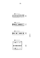
Фиг. 3 показывает примерный интерфейс 200, встроенный в уличный фонарь 150, который обеспечивает информацию пользователю. Интерфейс может включать в себя множество областей 240, каждая из которых обозначается как 310...350 в данном документе, которые могут быть закодированы цветом, который может использоваться, чтобы обеспечивать информацию (например, указания) пользователю. Резервные области 360 могут быть включены для будущего расширения. Цветовое кодирование обеспечивает простую визуальную идентификацию маршрута, поскольку цвет последовательно отображается от одного уличного фонаря 150 к следующему уличному фонарю 150.FIG. 3 shows an
Интерфейс 200 может также включать в себя область 220 пользовательского интерфейса, которая позволяет пользователю вводить информацию, например, желаемое место назначения. Область пользовательского интерфейса может включать в себя один или более хорошо известных интерфейсов "человек-машина". Например, хотя не показано, будет понятно, что область 220 интерфейса пользовательского ввода может включать в себя клавиатуру, чтобы вводить буквенно-цифровой символ, или может включать в себя устройство ввода типа пера, чтобы вводить буквенно-цифровую информацию, или может включать в себя систему распознавания голоса, которая позволяет пользователю вводить произносимые слова. Другое устройство ввода аналогичного типа может быть встроено в область 220 ввода, чтобы позволить пользователю вводить желаемую информацию. Кроме того, интерфейс 200 может включать в себя генератор для вывода звука (не показан), который может обеспечивать звуковой вывод в ответ на пользовательский ввод (например, "ваше место назначения находится в 3,2 милях к западу от этого местоположения") или может обеспечивать вывод большой громкости в случае чрезвычайного происшествия (например, "объявляется чрезвычайное положение, пожалуйста, следуйте за светом для эвакуации").The
В ответ на введенное желаемое место назначения центральный контроллер 130 определяет маршруты уличных фонарей 150 от введенного местоположения до местоположения назначения, при этом первый уличный фонарь 150 в маршруте ассоциирован с текущим местоположением, а последний уличный фонарь 150 в маршруте является уличным фонарем 150, ближайшим к месту назначения. Маршрут, ассоциированный с местоположением назначения, выбирается так, что соседние уличные фонари 150 могут быть использованы, чтобы обеспечивать информацию о направлении от текущего местоположения до уличного фонаря 150, ближайшего к месту назначения. Если желаемое место назначения находится за пределами локальной области, тогда центральный контроллер 130 может определять последний уличный фонарь 150, который должен быть в следующей области, и передавать обслуживание пользователя следующему центральному контроллеру.In response to the desired destination entered, the
В одном аспекте изобретения может быть выбран цвет направляющего управления, которому пользователь следует от уличного фонаря 150 к уличному фонарю 150, пока пользователь не достигнет желаемого места назначения. В другом аспекте, цвет управления может быть реализован на чередующихся уличных фонарях для обеспечения большего числа пользователей в системе. В одном аспекте изобретения направляющие цвета могут быть представлены только на двух или трех соседних уличных фонарях, и когда пользователь следует направляющим цветам, направляющие цвета будут последовательно зажигаться на следующем одном или двух уличных фонарях 150, когда пользователь приближается к уличному фонарю, показывающему направляющий цвет. В одном аспекте заданная скорость ходьбы может учитываться в определении времени, когда зажигать направляющие цвета на следующем одном или двух уличных фонарях. В одном аспекте изобретения пользователю может требоваться касаться фонаря для того, чтобы подтверждать, что пользователь следует за системой освещения.In one aspect of the invention, a guide control color may be selected that the user follows from the
В иллюстрированном примере, имеющем по меньшей мере пять цветных дисплеев 310…350 и две области 360, которые должны быть определены, допускается снабжать до семи отдельных пользователей примерным отображением. Однако использование пяти цветных дисплеев представлено только в целях объяснения изобретения и не должно рассматриваться как ограниченное пятью элементами и показанными цветами.In the illustrated example, having at least five
На фиг. 3 показан один пример пользовательского интерфейса (UI). В этом примерном аспекте изобретения, над пользовательским интерфейсом 200 присутствуют сигнальные лампы, которые обеспечивают направляющее управление к заданным местам назначения. В этом случае первая лампа ассоциирована с пользователем, после того как пользователь успешно задает свое место назначения. Первая лампа может представлять множество ламп, как показано на фиг. 2. Также показаны назначенные (заданные) цвета для торговых точек, если торговые точки хотят размещать рекламу. Или назначенные области могут быть ассоциированы с конкретными событиями или действиями (проведением мероприятий, встречами и т.д.), которые организации могут организовывать время от времени. Использование этих областей в интерфейсе может быть платной услугой, которая обеспечивает прибыль для локального города, чтобы поддерживать описываемую сеть. В этом случае, пользователь может касаться конкретного, рекламирующего торговую точку, цвета, и ему выдаются указания на рекламируемую торговую точку без дополнительного ввода. Как описано выше, множество видов способа ввода может быть использовано, например, блокнот для записей или раскрывающийся список. Кроме того, система может предлагать пользователю два режима работы, т.е. выбор и поиск.In FIG. 3 shows one example user interface (UI). In this exemplary aspect of the invention, signal lights are present above the
В одном аспекте изобретения, когда пользователь хочет найти место (т.е. место назначения, удаленное местоположение), он может подойти к ближайшему фонарному столбу 150, ввести или отыскивать свое желаемое место назначения. Система может тогда случайным образом указывать цвет для его использования и показывать цвет на UI 200. Сигнальная лампа начинает мигать на следующем фонарном столбе 150 в последовательности этим цветом в течение короткой продолжительности согласно расстоянию для пешей ходьбы до следующего фонарного столба 150. Таким образом, пользователь может следовать назначенному цвету, когда он появляется последовательно на следующем фонарном столбе 150 (назначенном в маршруте) к своему месту назначения. В одном аспекте изобретения интерфейс может включать в себя дополнительно звуковые команды, к которым пользователь может прислушиваться. В другом аспекте изобретения интерфейс может включать в себя интерфейс, чтобы принимать связь от устройства мобильной связи (например, Bluetooth, ближняя радиосвязь, сотовая связь) и/или обеспечивать протоколы связи, которые позволяют передавать указания мобильному телефону пользователя или устройству мобильной связи. Например, интерфейс может включать в себя идентификатор, с которым пользователь может «соединять» свое мобильное устройство для взаимодействия и обеспечения ввода через мобильное устройство. Инструкции о месте назначения (или другая информация) могут затем быть переданы мобильному устройству через интерфейс в дополнение к последовательному зажиганию направляющих ламп, как описано выше.In one aspect of the invention, when a user wants to find a place (i.e., a destination, a remote location), he can go to the
Место назначения может также быть задан на сервере 130, чтобы активировать специальное приложение. Например, система может позволять органам государственной власти, организациям или отдельным лицам, которые организуют действия, предлагать навигацию для их гостей. Таким образом, специальная область на интерфейсе может быть предусмотрена для единственного ввода заданного места назначения, и система работает, чтобы направлять пользователя к заданному месту назначения. Также заданное местоположение может быть ассоциировано с торговыми точками, чтобы рекламировать и привлекать клиентов в магазины. Эти виды услуги могут требовать, чтобы они были заданы на сервере с использованием администраторских привилегий. Услуга может быть платной услугой, для получения которой торговые точки платят за привилегию наличия заданного введенного местоположения.The destination can also be set on the
Как описано относительно произвольно выбранных, введенных пользователем мест назначения, система может включать в себя заданные места назначения, из которых пользователю необходимо лишь выбрать заданное место назначения для обеспечения достаточной информации, чтобы устанавливать маршрут между текущим фонарным столбом 150 и фонарным столбом 150, ближайшим к включенному заданному месту назначения. Этот аспект обеспечивает пользователю дополнительное удобство в том, что пользователь не должен вводить всю необходимую информацию, а обеспечивать только один ввод.As described with respect to randomly selected user-entered destinations, the system may include predetermined destinations from which the user only needs to select a predetermined destination to provide sufficient information to establish a route between the
Как описано выше, ввод, осуществленный пользователем (которые представляют собой место назначения) с конкретного фонарного столба 150, имеющего физический идентификатор местоположения и идентификатор сети передачи данных, затем используются центральным контроллером 130, чтобы определять маршрут до желаемого места назначения. Маршрут включает в себя те фонарные столбы 150 среди множества фонарных столбов 150 в управлении центрального контроллера 130, которые могут быть использованы, чтобы направлять пользователя от текущего фонарного столба 150 к следующему фонарному столбу 150. Как описано выше, пользователю назначается цвет (визуальный указатель), которому пользователь затем последовательно следует от текущего фонарного столба 150 к следующему фонарному столбу 150. В одном аспекте центральный контроллер 130 может определять весь маршрут фонарных столбов 150 и может затем обеспечивать передачу данных следующему фонарному столбу 150 в подходящее время (на основании скорости ходьбы). Или контроллер может определять следующий фонарный столб 150, когда пользователь приближается к текущему фонарному столбу 150, и затем обеспечивает передачу данных динамически определяемому следующему фонарному столбу. Таким образом, назначение следующего фонарного столба 150 в следующем временном интервале выполняется динамически.As described above, user input (which represents the destination) from a
Фиг. 4 иллюстрирует примерные отображения, обозначенные (a), (b), (c) и (d), в которых отображение на интерфейсе 200 может последовательно продвигаться направленным образом (т.е. в направлении стрелок), чтобы советовать человеку, принимая во внимание световые сигналы, следовать в том же направлении движения. Эта форма последовательного отображения для обеспечения информации о направлении может быть ценной в чрезвычайной ситуации, в которой местные органы самоуправления могут направлять людей в зоне чрезвычайной обстановки за пределы зоны чрезвычайной обстановки. В этом вопросе городской центр 120 управления может обеспечивать центральному контроллеру 130 удаленное местоположение за пределами зоны, которая, как считается, находится в чрезвычайной ситуации. Центральный контроллер 130 может затем определять маршрут от каждого уличного фонаря 150, чтобы минимизировать расстояние ходьбы между текущим уличным фонарем 150 и удаленным местоположением. Определенное направление движения обеспечивает безопасную эвакуацию людей в зоне чрезвычайной ситуации. Таким образом, локальный центральный компьютер 130 (или серверы) вмешается в управление интерфейса, так что экстренное направление движения сможет отображаться на уличных фонарях. Кроме того, лампы 160, ассоциированные с уличными фонарями 150, могут мигать (включаться/выключаться) с известной частотой, что обеспечивает визуальное указание направления движения. Таким образом, лампы 160 могут последовательно управляться, в свою очередь, так что включение/выключение ламп 160 обеспечивает иллюстрацию движения и, следовательно, направление передвижения для эвакуации зоны.FIG. 4 illustrates exemplary mappings indicated by (a), (b), (c) and (d) in which the display on the
В качестве альтернативы, фиг. 4 может представлять потолочное освещение 140 (см. фиг. 1) внутри сооружения. В этом случае управление освещением может быть использовано для обеспечения указания людям в зоне о том, чтобы следовать направлению освещения для того, чтобы выйти из зоны. Например, в случае на фиг. 4(a) три секции световой панели выделяются, для формирования стрелки, чтобы указывать направление передвижения. На фиг. 4(b)/(c) лампы в одной секции световой панели могут мигать с частотой, которая обеспечивает указание направления, как описано выше. На фиг. 4(d), если лампы с множеством цветов доступно, тогда лампы могут мигать с частотой, которая обеспечивает указание направления. Как будет понятно, в этом случае, рассматривается ли внутреннее или внешнее освещение, частота, с которой лампы включаются и выключаются, будет повторяться так, что освещение не уходит от пользователя. Например, когда включение ламп последовательно продвигается к следующей лампе, после того как заданное число ламп было последовательно включено/выключено, комбинация опять повторяется с первоначальной лампы. Таким образом, освещение будет обеспечивать пользователю иллюзию направления, когда лампы последовательно продвигаются, и рисунок повторяется.Alternatively, FIG. 4 may represent ceiling lighting 140 (see FIG. 1) within a structure. In this case, lighting control can be used to provide an indication to people in the zone to follow the direction of lighting in order to leave the zone. For example, in the case of FIG. 4 (a) three sections of the light panel are allocated to form an arrow to indicate a direction of movement. In FIG. 4 (b) / (c) lamps in one section of the light panel can flash at a frequency that provides direction indication as described above. In FIG. 4 (d), if multi-color lamps are available, then the lamps may flash at a frequency that provides direction indication. As will be understood, in this case, whether the internal or external lighting is considered, the frequency with which the lamps are turned on and off will be repeated so that the lighting does not leave the user. For example, when turning on the lamps sequentially advances to the next lamp, after the predetermined number of lamps has been sequentially turned on / off, the combination is again repeated from the original lamp. Thus, the lighting will provide the user with the illusion of direction when the lamps are progressively moving and the pattern repeats.
Обнаружение маршрута может быть реализовано согласно текущему положению и положению места назначения. В одном аспекте изобретения маршрут может быть вычислен с помощью хорошо известного способа навигации (например, GPS), и затем маршрут сопоставляется с маршрутом с инфраструктурой освещения. Таким образом, в то время как GPS может обеспечивать прямой маршрут к конечному месту назначения, центральный контроллер 130 переводит обеспеченный маршрут в маршрут, который регулируется с помощью уличных столбов 150 в локальной сети электроснабжения. В одном аспекте маршрут может хранить местоположение фонарного столба 150 и выбирать следующий фонарный столб 150 по маршруту на основании заданного направления ходьбы и скорости ходьбы (т.е. оцененное географическое положение) или посредством подтверждения пользователем его присутствия у фонарного столба 150. В этом случае, центральный контроллер 130 может сохранять положения каждого фонарного столба 150 на основании их географического положения (например, долгота/широта), их положения в общегородской сети, относительного положения относительно фиксированных местоположений (например, первый фонарный столб 150 в цепи питания силовой линии) и т.д. Кроме того, фонарный столб 150 может включать в себя GPS-систему определения местоположения, которая обеспечивает информацию о географическом положении центральному контроллеру 130. Как описано выше, каждый фонарный столб 150 дополнительно идентифицируется по уникальному адресу, который идентифицирует фонарный столб 150 в сети передачи данных.Route detection can be implemented according to the current position and location of the destination. In one aspect of the invention, a route can be calculated using a well-known navigation method (e.g., GPS), and then the route is mapped to a route with lighting infrastructure. Thus, while GPS can provide a direct route to the final destination, the
В качестве альтернативы, центральный компьютер 130 может определять маршрут на основании уже заданных путей маршрутизации, которые могут быть реализованы за счет непосредственного использования информации о местоположении позиции лампы, чтобы вычислять оптимизированный маршрут. Например, местоположение места назначения может быть назначено в местоположение конкретного уличного фонаря 150, и когда это местоположение места назначения вводится, маршрут от местоположения текущего уличного фонаря 150 может быть определен.Alternatively, the
Основная процедура для реализации уличной навигационной системы, описанной в данном документе, заключается в следующем.The basic procedure for implementing a street navigation system described in this document is as follows.
Определяется базовый интервал времени. Базовый интервал времени может представлять время, в течение которого пользователь, как ожидается, должен достигать следующего фонарного столба 150. Например, базовый интервал времени может быть выбран на основании заданной скорости ходьбы (например, 3 мили в час). Таким образом, время, в которое следующий фонарный столб 150 в маршруте примет сигнал, чтобы начинать работу, будет в интервалах определенного времени (т.е. базового интервала времени). Цветной свет назначается в базовом интервале времени на текущем фонарном столбе на определенный период времени, и затем сигнал отправляется следующему фонарному столбу в следующем базовом интервале времени.The base time interval is determined. The base time interval may represent the time during which the user is expected to reach the
Кроме того, находясь на фонарном столбе, визуальный указатель (цвет) мигает последовательно на фонарных столбах в течение заданного времени. Время, в течение которого визуальный указатель мигает на фонарном столбе 150, может также быть основано на базовом интервале времени или может быть отменено пользователем, когда пользователь контактирует со следующим интерфейсом. Кроме того, базовый интервал времени может быть определен на основании того, определен ли следующий фонарный столб 150 как следующий фонарный столб 150 или каждый другой (второй или чередующийся) фонарный столб 150, чтобы передавать информацию для пользователя. Таким образом, предположим, что решено, что вследствие нагрузки системы, размещения инфраструктуры, условий освещения и т.д. каждый второй фонарный столб 150 выделяется для маршрута, и дополнительно предположим, что средняя скорость ходьбы является критерием определения, тогда базовый интервал времени будет вдвое большим по сравнению с базовым интервалом времени в случае, когда каждый фонарный столб 150 был выбран для того, чтобы передавать информацию для пользователя.In addition, being on the lamppost, the visual indicator (color) flashes sequentially on the lampposts for a predetermined time. The time during which the visual indicator flashes on the
Кроме того, определенное время, которое используется в фонарном столбе 150, чтобы определять частоту мигания, может быть разделено в случае двух или более цветов, встречающихся вместе на одном и том же фонарном столбе в одном и том же временном интервале. Цвета могут светиться по очереди. Разделение должно быть ограничено. Обычно фонарь не на перекрестке может иметь лампы в двух направлениях, в то время как фонарь на перекрестке может иметь 4 направления.In addition, the specific time that is used in the
Мигание лампы повторяется после некоторого периода времени (заданного времени), чтобы позволять людям всегда иметь возможность видеть сигнал рядом с ними (например, мигание лампы для каждого пользователя может происходить с частотой 8 раз в базовом интервале). Частота повторения вывода света может регулироваться согласно условиям использования. Например, частота мигания может быть длиннее, когда присутствует много пользователей.The lamp flashes again after a certain period of time (a given time) to allow people to always be able to see the signal next to them (for example, the lamp blinking for each user can occur at a frequency of 8 times in the base interval). The light output repetition rate can be adjusted according to the conditions of use. For example, the blink rate may be longer when many users are present.
Если слишком много сигналов встречаются вместе, некоторые сигналы могут задерживаться в течение одного дополнительного временного интервала.If too many signals occur together, some signals may be delayed for one additional time interval.
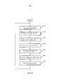
Фиг. 5A иллюстрирует примерный процесс, который может работать в центральном контроллере 130 в соответствии с принципами изобретения. В этом примерном варианте осуществления текущее положение и маршрут получается для каждого цвета, который должен быть использован, на этапе 510. Т.е. в системе с множеством пользователей, как было описано, рассматриваются маршруты для каждого назначенного цвета, и цвета или визуальные указатели соответствующим образом обеспечиваются уличным фонарям 150 в маршруте, назначенном этому цвету. На этапе 520 определяется или получается следующий столб или уличный фонарь 150 в маршруте, назначенном посредством цвета. На этапе 530 информация, касающаяся цвета, отправляется следующему столбу в маршруте, ассоциированном с назначенным цветом. На этапе 540 выполняется определение, касающееся числа цветов, используемых на следующем столбе, ассоциированном с каждым из маршрутов, которым следующий столб предназначается. Например, следующий столб в каждом маршруте может быть на главном перекрестке, и множество различных маршрутов сходятся на этом столбе приблизительно в одно и то же время (или в назначенном интервале времени). На этапе 550 частота повторения мерцания назначенного цвета на столбе регулируется так, что каждый из цветов, назначенных столбу, мигает заданное число раз в течение периода, когда цвет назначается столбу. На этапе 560 другой маршрут вычисляется, когда новый пользователь входит в систему. На этапе 570 система ожидает перехода к этапу 510, чтобы продолжать процесс определения следующего столба для каждого маршрута, существующего в настоящее время в системе.FIG. 5A illustrates an example process that may operate in a
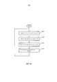
Фиг. 5B иллюстрирует примерную обработку на каждом следующем уличном фонаре 150 в маршруте уличных фонарей 150 в соответствии с принципами изобретения. В этом примерном процессе информация, касающаяся цветов (ассоциированных с пользователями), которая должна быть использована, получается от центрального контроллера 130 в блоке 610. В блоке 620 число полученных цветов затем определяет частоту мигания каждого цвета в течение периода, когда цвета для столба должны мигать. В блоке 630 выполняется ожидание в течение следующего временного интервала, и затем на этапе 640 назначенные цвета освещения мигают с частотой, основанной на первоначально предусмотренном числе цветов. Каждый уличный фонарь 150 задействует свою систему освещения для направления в подходящий момент времени в соответствии с командами, выдаваемыми центральным контроллером 130.FIG. 5B illustrates exemplary processing at each
Вышеописанные способы согласно настоящему изобретению могут быть реализованы в аппаратных средствах, микропрограммных средствах или как программное обеспечение или компьютерный код, который может быть сохранен на носителе записи информации, таком как CD-ROM, RAM, гибкий диск, жесткий диск или магнитооптический диск, или компьютерный код, загружаемый по сети, первоначально сохраненный на удаленном носителе записи или энергонезависимом машинно-читаемом носителе и который должен быть сохранен на локальном носителе записи, так что способы, описанные в данном документе, могут быть воспроизведены в таком программном обеспечении, которое сохранено на носителе записи, с помощью компьютера общего назначения или специального процессора или в программируемых или специализированных аппаратных средствах, таких как ASIC или FPGA. Как будет понятно специалистам в данной области техники, компьютер, процессор, микропроцессор, контроллер или программируемые аппаратные средства включают в себя компоненты памяти, например, RAM, ROM, флэш-память и т.д., которые могут хранить или принимать программное обеспечение или компьютерный код, который, когда к нему осуществляется доступ, и он выполняется компьютером, процессором или аппаратными средствами, реализует способы обработки, описанные в данном документе. Кроме того, будет понятно, что когда компьютер общего назначения осуществляет доступ к коду для реализации обработки, показанной в данном документе, выполнение кода преобразует компьютер общего назначения в специализированный компьютер для выполнения обработки, показанной в данном документе.The above methods according to the present invention can be implemented in hardware, firmware, or as software or computer code that can be stored on an information recording medium such as a CD-ROM, RAM, floppy disk, hard disk or magneto-optical disk, or computer network-loaded code originally stored on a remote recording medium or non-volatile machine-readable medium and which must be stored on a local recording medium, so that the methods those described in this document can be reproduced in such software as is stored on the recording medium, using a general-purpose computer or special processor, or in programmable or specialized hardware such as ASIC or FPGA. As will be appreciated by those skilled in the art, a computer, processor, microprocessor, controller, or programmable hardware includes memory components, such as RAM, ROM, flash memory, etc. that can store or receive software or computer code that, when accessed and executed by a computer, processor, or hardware, implements the processing methods described in this document. In addition, it will be understood that when a general-purpose computer accesses the code to implement the processing shown in this document, code execution converts the general-purpose computer to a dedicated computer to perform the processing shown in this document.
В то время как было показано, описано, и обращено внимание на фундаментальные и новейшие признаки настоящего изобретения, которые применены к предпочтительным вариантам его осуществления, будет понятно, что различные упущения и замещения и изменения в описанном устройстве, в форме и деталях раскрытых устройств и в их работе могут быть выполнены специалистами в данной области техники без отступления от сущности настоящего изобретения.While it has been shown, described, and paid attention to the fundamental and latest features of the present invention, which are applied to the preferred options for its implementation, it will be understood that various omissions and substitutions and changes in the described device, in the form and details of the disclosed devices and in their work can be performed by specialists in this field of technology without departing from the essence of the present invention.
Определенно имеется ввиду, что все комбинации этих элементов, которые выполняют по существу одинаковую функцию по существу одинаковым способом, чтобы получить одинаковые результаты, находятся в объеме изобретения. Замещения элементов из одного описанного варианта осуществления в другом также полностью подразумеваются и рассматриваются.Definitely, it is understood that all combinations of these elements, which perform essentially the same function in essentially the same way to obtain the same results, are within the scope of the invention. Substitutions of elements from one described embodiment to another are also fully understood and contemplated.
Claims (31)
Applications Claiming Priority (3)
| Application Number | Priority Date | Filing Date | Title |
|---|---|---|---|
| US201261641943P | 2012-05-03 | 2012-05-03 | |
| US61/641,943 | 2012-05-03 | ||
| PCT/IB2013/053264 WO2013164740A1 (en) | 2012-05-03 | 2013-04-25 | Streetwise navigation system using infrastructure elements |
Publications (2)
| Publication Number | Publication Date |
|---|---|
| RU2014148546A RU2014148546A (en) | 2016-06-27 |
| RU2626028C2 true RU2626028C2 (en) | 2017-07-21 |
Family
ID=48577182
Family Applications (1)
| Application Number | Title | Priority Date | Filing Date |
|---|---|---|---|
| RU2014148546A RU2626028C2 (en) | 2012-05-03 | 2013-04-25 | Street navigation system using infrastructure elements |
Country Status (6)
| Country | Link |
|---|---|
| US (1) | US9696159B2 (en) |
| EP (1) | EP2845177A1 (en) |
| JP (1) | JP2015519650A (en) |
| CN (1) | CN104272359B (en) |
| RU (1) | RU2626028C2 (en) |
| WO (1) | WO2013164740A1 (en) |
Families Citing this family (19)
| Publication number | Priority date | Publication date | Assignee | Title |
|---|---|---|---|---|
| EP2976928B1 (en) | 2013-03-18 | 2020-02-26 | Signify Holding B.V. | Methods and apparatus for information management and control of outdoor lighting networks |
| WO2015082717A1 (en) * | 2013-12-06 | 2015-06-11 | Televic Rail Nv | Personalized guidance system |
| JP6025267B2 (en) * | 2014-06-20 | 2016-11-16 | 見治 西石垣 | Survey type navigation system |
| EP3506724A3 (en) * | 2014-11-10 | 2019-08-14 | Schreder | Network of lights |
| CN104807459A (en) * | 2015-04-30 | 2015-07-29 | 吴博 | Indoor navigation system and navigation method thereof |
| JP6467312B2 (en) * | 2015-07-31 | 2019-02-13 | 株式会社Nttドコモ | Navigation system |
| CN106895836A (en) * | 2015-12-17 | 2017-06-27 | 腾讯科技(深圳)有限公司 | Indoor navigation method and device |
| US11828859B2 (en) | 2016-05-07 | 2023-11-28 | Canyon Navigation, LLC | Navigation using self-describing fiducials |
| US10417469B2 (en) | 2016-05-07 | 2019-09-17 | Morgan E. Davidson | Navigation using self-describing fiducials |
| US11036946B2 (en) | 2016-05-07 | 2021-06-15 | Canyon Navigation, LLC | Navigation using self-describing fiducials |
| JP2018055505A (en) * | 2016-09-29 | 2018-04-05 | 富士通株式会社 | Guidance system, guidance method, guidance program and lighting device |
| CN108091088A (en) * | 2016-11-21 | 2018-05-29 | 波士德媒体股份有限公司 | The intelligent designation system of house close quarters |
| DE102017205075A1 (en) * | 2017-03-27 | 2018-09-27 | Ford Global Technologies, Llc | Vehicle-based control of lighting |
| CN110892757B (en) * | 2017-07-21 | 2023-09-26 | 昕诺飞控股有限公司 | End node for controlling low power wide area network |
| CN110440807A (en) * | 2019-08-13 | 2019-11-12 | Oppo(重庆)智能科技有限公司 | Indoor navigation method and device, storage medium and electronic equipment |
| CN111337035A (en) * | 2020-02-27 | 2020-06-26 | 杭州勇电照明有限公司 | Intelligent light route guiding method |
| US11614332B2 (en) * | 2020-12-17 | 2023-03-28 | Adobe Inc. | Systems for generating indications of traversable paths |
| CN113012595A (en) * | 2021-03-22 | 2021-06-22 | 四川数字可见科技有限公司 | Crowd evacuation system in emergency |
| KR102418566B1 (en) * | 2021-12-22 | 2022-07-08 | 재단법인 지능형자동차부품진흥원 | Autonomous driving safety control system based on edge infrastructure and method thereof |
Citations (4)
| Publication number | Priority date | Publication date | Assignee | Title |
|---|---|---|---|---|
| JP2006233503A (en) * | 2005-02-23 | 2006-09-07 | Shin Sangyo Souzou Kenkyu Kiko | Pedestrian guiding method and road marking device |
| NL1035392C1 (en) * | 2008-05-06 | 2009-11-09 | Ledexpert B V | Street route indicator system, has LEDs arranged in street lamps and emitting light for guiding user on journey along street, where LEDs emit light with unique color associated with user |
| DE102009031019A1 (en) * | 2009-06-29 | 2010-12-30 | Siemens Aktiengesellschaft | System for providing personalized navigation information for guiding e.g. person to location, has display devices integrated in movement spaces, and displaying navigation information, when persons are found near display devices |
| US20110022201A1 (en) * | 2008-04-03 | 2011-01-27 | Koninklijke Philips Electronics N.V. | Method of guiding a user from an initial position to a destination in a public area |
Family Cites Families (23)
| Publication number | Priority date | Publication date | Assignee | Title |
|---|---|---|---|---|
| JPS548499A (en) * | 1977-06-22 | 1979-01-22 | Hitachi Shomei Kk | Escape guide device |
| US5673039A (en) * | 1992-04-13 | 1997-09-30 | Pietzsch Ag | Method of monitoring vehicular traffic and of providing information to drivers and system for carring out the method |
| JP2002108942A (en) * | 2000-09-28 | 2002-04-12 | Mitsubishi Electric Corp | Information providing system |
| JP2003108052A (en) | 2001-09-29 | 2003-04-11 | Keiji Matsuo | Refuge leading guide display unit for prevention of disasters |
| JP2004279986A (en) * | 2003-03-18 | 2004-10-07 | Sanyo Electric Co Ltd | Inside illumination type indicator lamp |
| JP2005092428A (en) * | 2003-09-16 | 2005-04-07 | Toshiba Corp | Tunnel lighting controller |
| JP2005234768A (en) | 2004-02-18 | 2005-09-02 | Sekisui Jushi Co Ltd | Evacuation guiding system |
| US7277018B2 (en) | 2004-09-17 | 2007-10-02 | Incident Alert Systems, Llc | Computer-enabled, networked, facility emergency notification, management and alarm system |
| KR100761045B1 (en) | 2005-07-01 | 2007-09-21 | 서울메트로 | Advertisement and emergency guidance system for sub way platform |
| CN1941028A (en) | 2005-09-07 | 2007-04-04 | 马飞 | Address positioning and road guiding method |
| JP2007156651A (en) | 2005-12-01 | 2007-06-21 | Shomei:Kk | Guidance display system and guidance display device |
| FR2896993B1 (en) | 2006-02-08 | 2008-09-26 | Cooper Menvier Sas Soc Par Act | EMERGENCY EXHAUST ROAD DISPLAY SYSTEM |
| JP4726648B2 (en) * | 2006-02-20 | 2011-07-20 | 中国電力株式会社 | Navigation system and position information providing server |
| DE102007033391A1 (en) | 2007-07-18 | 2009-01-22 | Robert Bosch Gmbh | Information device, method for information and / or navigation of a person and computer program |
| WO2009038557A1 (en) * | 2007-09-19 | 2009-03-26 | United Technologies Corporation | Model-based egress support system |
| US8138690B2 (en) | 2008-04-14 | 2012-03-20 | Digital Lumens Incorporated | LED-based lighting methods, apparatus, and systems employing LED light bars, occupancy sensing, local state machine, and meter circuit |
| CN101639977A (en) * | 2008-07-28 | 2010-02-03 | 刘爱民 | Guidepost positioning intelligent transportation system |
| US8653984B2 (en) | 2008-10-24 | 2014-02-18 | Ilumisys, Inc. | Integration of LED lighting control with emergency notification systems |
| CN102474954B (en) * | 2009-08-05 | 2015-10-21 | 皇家飞利浦电子股份有限公司 | Light-guiding system and the method for controlling this light-guiding system |
| US8364398B2 (en) | 2009-08-28 | 2013-01-29 | Navteq B.V. | Method of operating a navigation system to provide route guidance |
| US8306737B2 (en) | 2010-03-24 | 2012-11-06 | Telenav, Inc. | Navigation system with route planning and method of operation thereof |
| JP5569365B2 (en) * | 2010-11-30 | 2014-08-13 | アイシン・エィ・ダブリュ株式会社 | Guide device, guide method, and guide program |
| CN102103798B (en) | 2011-02-10 | 2014-04-16 | 惠州Tcl移动通信有限公司 | Traffic lights state information prompt system and method thereof |
-
2013
- 2013-04-25 RU RU2014148546A patent/RU2626028C2/en not_active IP Right Cessation
- 2013-04-25 WO PCT/IB2013/053264 patent/WO2013164740A1/en active Application Filing
- 2013-04-25 CN CN201380023235.6A patent/CN104272359B/en not_active Expired - Fee Related
- 2013-04-25 EP EP13727377.7A patent/EP2845177A1/en not_active Withdrawn
- 2013-04-25 JP JP2015509535A patent/JP2015519650A/en not_active Ceased
- 2013-04-25 US US14/397,952 patent/US9696159B2/en not_active Expired - Fee Related
Patent Citations (4)
| Publication number | Priority date | Publication date | Assignee | Title |
|---|---|---|---|---|
| JP2006233503A (en) * | 2005-02-23 | 2006-09-07 | Shin Sangyo Souzou Kenkyu Kiko | Pedestrian guiding method and road marking device |
| US20110022201A1 (en) * | 2008-04-03 | 2011-01-27 | Koninklijke Philips Electronics N.V. | Method of guiding a user from an initial position to a destination in a public area |
| NL1035392C1 (en) * | 2008-05-06 | 2009-11-09 | Ledexpert B V | Street route indicator system, has LEDs arranged in street lamps and emitting light for guiding user on journey along street, where LEDs emit light with unique color associated with user |
| DE102009031019A1 (en) * | 2009-06-29 | 2010-12-30 | Siemens Aktiengesellschaft | System for providing personalized navigation information for guiding e.g. person to location, has display devices integrated in movement spaces, and displaying navigation information, when persons are found near display devices |
Also Published As
| Publication number | Publication date |
|---|---|
| CN104272359A (en) | 2015-01-07 |
| US9696159B2 (en) | 2017-07-04 |
| CN104272359B (en) | 2016-09-28 |
| EP2845177A1 (en) | 2015-03-11 |
| US20150127251A1 (en) | 2015-05-07 |
| JP2015519650A (en) | 2015-07-09 |
| WO2013164740A1 (en) | 2013-11-07 |
| RU2014148546A (en) | 2016-06-27 |
Similar Documents
| Publication | Publication Date | Title |
|---|---|---|
| RU2626028C2 (en) | Street navigation system using infrastructure elements | |
| US10096246B2 (en) | Using lighting and other streetside devices to indicate parking space availability and navigation information | |
| JP5355374B2 (en) | Personalized user routing and recommendations | |
| RU2571450C2 (en) | Method of multimodal navigation | |
| EP1541968B1 (en) | Guiding device, system and method | |
| US20100057346A1 (en) | Intelligent Travel Routing System and Method | |
| US20080021632A1 (en) | Traffic Condition Report Device, System Thereof, Method Thereof, Program For Executing The Method, And Recording Medium Containing The Program | |
| Liao | Using a smartphone application to support visually impaired pedestrians at signalized intersection crossings | |
| EP1550843A1 (en) | Navigation when deviating from planned route | |
| Castillo-Cara et al. | Ray: Smart indoor/outdoor routes for the blind using Bluetooth 4.0 BLE | |
| JP2007257463A (en) | Directional voice guide system and directional voice guide method | |
| JP2008086024A (en) | Positional information transmitting unit and positional information providing system | |
| JP2002286491A (en) | Portable navigation system | |
| JP2015219070A (en) | Information provision system, information provision server, information provision method, and program | |
| JP5204792B2 (en) | Navigation system, navigation server, navigation device, navigation method, and program | |
| KR102460709B1 (en) | Smart pavement marker and service providing system using the same | |
| JP2014006076A (en) | Navigation device, navigation system, terminal device, server device, navigation method, and program | |
| JP2012185028A (en) | Passage information registration device, passage route prediction device, passage information registration system, passage route prediction system, passage information registration method, passage route prediction method, and program | |
| JP6268214B2 (en) | Analysis evaluation system, analysis evaluation method, information processing apparatus, and analysis evaluation program | |
| KR102141239B1 (en) | System and method for detecting the location of a device based on a mesh network | |
| JP2004012155A (en) | Navigation system for pedestrian and personal digital assistance | |
| JP2013221927A (en) | Analysis evaluation system, analysis evaluation device, analysis evaluation method, and program | |
| Wasserburger et al. | Web-based city maps for blind and visually impaired | |
| JP5303485B2 (en) | Route guidance system, terminal device, route search server, route guidance method, and program | |
| JP4899839B2 (en) | Mobile terminal and program thereof |
Legal Events
| Date | Code | Title | Description |
|---|---|---|---|
| HZ9A | Changing address for correspondence with an applicant | ||
| MM4A | The patent is invalid due to non-payment of fees |
Effective date: 20180426 |