JP7190450B2 - Dry stripping of boron carbide hardmask - Google Patents
Dry stripping of boron carbide hardmask Download PDFInfo
- Publication number
- JP7190450B2 JP7190450B2 JP2019564959A JP2019564959A JP7190450B2 JP 7190450 B2 JP7190450 B2 JP 7190450B2 JP 2019564959 A JP2019564959 A JP 2019564959A JP 2019564959 A JP2019564959 A JP 2019564959A JP 7190450 B2 JP7190450 B2 JP 7190450B2
- Authority
- JP
- Japan
- Prior art keywords
- process gas
- boron carbide
- pressure vessel
- substrate
- substrates
- Prior art date
- Legal status (The legal status is an assumption and is not a legal conclusion. Google has not performed a legal analysis and makes no representation as to the accuracy of the status listed.)
- Active
Links
Images


Classifications
-
- H—ELECTRICITY
- H01—ELECTRIC ELEMENTS
- H01L—SEMICONDUCTOR DEVICES NOT COVERED BY CLASS H10
- H01L21/00—Processes or apparatus adapted for the manufacture or treatment of semiconductor or solid state devices or of parts thereof
- H01L21/70—Manufacture or treatment of devices consisting of a plurality of solid state components formed in or on a common substrate or of parts thereof; Manufacture of integrated circuit devices or of parts thereof
- H01L21/71—Manufacture of specific parts of devices defined in group H01L21/70
- H01L21/768—Applying interconnections to be used for carrying current between separate components within a device comprising conductors and dielectrics
- H01L21/76838—Applying interconnections to be used for carrying current between separate components within a device comprising conductors and dielectrics characterised by the formation and the after-treatment of the conductors
- H01L21/76841—Barrier, adhesion or liner layers
- H01L21/76853—Barrier, adhesion or liner layers characterized by particular after-treatment steps
- H01L21/76865—Selective removal of parts of the layer
-
- H—ELECTRICITY
- H01—ELECTRIC ELEMENTS
- H01L—SEMICONDUCTOR DEVICES NOT COVERED BY CLASS H10
- H01L21/00—Processes or apparatus adapted for the manufacture or treatment of semiconductor or solid state devices or of parts thereof
- H01L21/02—Manufacture or treatment of semiconductor devices or of parts thereof
- H01L21/04—Manufacture or treatment of semiconductor devices or of parts thereof the devices having at least one potential-jump barrier or surface barrier, e.g. PN junction, depletion layer or carrier concentration layer
- H01L21/18—Manufacture or treatment of semiconductor devices or of parts thereof the devices having at least one potential-jump barrier or surface barrier, e.g. PN junction, depletion layer or carrier concentration layer the devices having semiconductor bodies comprising elements of Group IV of the Periodic System or AIIIBV compounds with or without impurities, e.g. doping materials
- H01L21/30—Treatment of semiconductor bodies using processes or apparatus not provided for in groups H01L21/20 - H01L21/26
- H01L21/31—Treatment of semiconductor bodies using processes or apparatus not provided for in groups H01L21/20 - H01L21/26 to form insulating layers thereon, e.g. for masking or by using photolithographic techniques; After treatment of these layers; Selection of materials for these layers
- H01L21/3105—After-treatment
- H01L21/311—Etching the insulating layers by chemical or physical means
- H01L21/31105—Etching inorganic layers
- H01L21/31111—Etching inorganic layers by chemical means
- H01L21/31116—Etching inorganic layers by chemical means by dry-etching
- H01L21/31122—Etching inorganic layers by chemical means by dry-etching of layers not containing Si, e.g. PZT, Al2O3
-
- C—CHEMISTRY; METALLURGY
- C23—COATING METALLIC MATERIAL; COATING MATERIAL WITH METALLIC MATERIAL; CHEMICAL SURFACE TREATMENT; DIFFUSION TREATMENT OF METALLIC MATERIAL; COATING BY VACUUM EVAPORATION, BY SPUTTERING, BY ION IMPLANTATION OR BY CHEMICAL VAPOUR DEPOSITION, IN GENERAL; INHIBITING CORROSION OF METALLIC MATERIAL OR INCRUSTATION IN GENERAL
- C23C—COATING METALLIC MATERIAL; COATING MATERIAL WITH METALLIC MATERIAL; SURFACE TREATMENT OF METALLIC MATERIAL BY DIFFUSION INTO THE SURFACE, BY CHEMICAL CONVERSION OR SUBSTITUTION; COATING BY VACUUM EVAPORATION, BY SPUTTERING, BY ION IMPLANTATION OR BY CHEMICAL VAPOUR DEPOSITION, IN GENERAL
- C23C16/00—Chemical coating by decomposition of gaseous compounds, without leaving reaction products of surface material in the coating, i.e. chemical vapour deposition [CVD] processes
- C23C16/22—Chemical coating by decomposition of gaseous compounds, without leaving reaction products of surface material in the coating, i.e. chemical vapour deposition [CVD] processes characterised by the deposition of inorganic material, other than metallic material
- C23C16/30—Deposition of compounds, mixtures or solid solutions, e.g. borides, carbides, nitrides
- C23C16/32—Carbides
-
- C—CHEMISTRY; METALLURGY
- C23—COATING METALLIC MATERIAL; COATING MATERIAL WITH METALLIC MATERIAL; CHEMICAL SURFACE TREATMENT; DIFFUSION TREATMENT OF METALLIC MATERIAL; COATING BY VACUUM EVAPORATION, BY SPUTTERING, BY ION IMPLANTATION OR BY CHEMICAL VAPOUR DEPOSITION, IN GENERAL; INHIBITING CORROSION OF METALLIC MATERIAL OR INCRUSTATION IN GENERAL
- C23C—COATING METALLIC MATERIAL; COATING MATERIAL WITH METALLIC MATERIAL; SURFACE TREATMENT OF METALLIC MATERIAL BY DIFFUSION INTO THE SURFACE, BY CHEMICAL CONVERSION OR SUBSTITUTION; COATING BY VACUUM EVAPORATION, BY SPUTTERING, BY ION IMPLANTATION OR BY CHEMICAL VAPOUR DEPOSITION, IN GENERAL
- C23C16/00—Chemical coating by decomposition of gaseous compounds, without leaving reaction products of surface material in the coating, i.e. chemical vapour deposition [CVD] processes
- C23C16/22—Chemical coating by decomposition of gaseous compounds, without leaving reaction products of surface material in the coating, i.e. chemical vapour deposition [CVD] processes characterised by the deposition of inorganic material, other than metallic material
- C23C16/30—Deposition of compounds, mixtures or solid solutions, e.g. borides, carbides, nitrides
- C23C16/38—Borides
-
- H—ELECTRICITY
- H01—ELECTRIC ELEMENTS
- H01L—SEMICONDUCTOR DEVICES NOT COVERED BY CLASS H10
- H01L21/00—Processes or apparatus adapted for the manufacture or treatment of semiconductor or solid state devices or of parts thereof
- H01L21/02—Manufacture or treatment of semiconductor devices or of parts thereof
- H01L21/02041—Cleaning
- H01L21/02043—Cleaning before device manufacture, i.e. Begin-Of-Line process
- H01L21/02046—Dry cleaning only
-
- H—ELECTRICITY
- H01—ELECTRIC ELEMENTS
- H01L—SEMICONDUCTOR DEVICES NOT COVERED BY CLASS H10
- H01L21/00—Processes or apparatus adapted for the manufacture or treatment of semiconductor or solid state devices or of parts thereof
- H01L21/02—Manufacture or treatment of semiconductor devices or of parts thereof
- H01L21/02041—Cleaning
- H01L21/02057—Cleaning during device manufacture
- H01L21/0206—Cleaning during device manufacture during, before or after processing of insulating layers
-
- H—ELECTRICITY
- H01—ELECTRIC ELEMENTS
- H01L—SEMICONDUCTOR DEVICES NOT COVERED BY CLASS H10
- H01L21/00—Processes or apparatus adapted for the manufacture or treatment of semiconductor or solid state devices or of parts thereof
- H01L21/02—Manufacture or treatment of semiconductor devices or of parts thereof
- H01L21/02104—Forming layers
- H01L21/02107—Forming insulating materials on a substrate
- H01L21/02109—Forming insulating materials on a substrate characterised by the type of layer, e.g. type of material, porous/non-porous, pre-cursors, mixtures or laminates
- H01L21/02112—Forming insulating materials on a substrate characterised by the type of layer, e.g. type of material, porous/non-porous, pre-cursors, mixtures or laminates characterised by the material of the layer
- H01L21/02123—Forming insulating materials on a substrate characterised by the type of layer, e.g. type of material, porous/non-porous, pre-cursors, mixtures or laminates characterised by the material of the layer the material containing silicon
- H01L21/02126—Forming insulating materials on a substrate characterised by the type of layer, e.g. type of material, porous/non-porous, pre-cursors, mixtures or laminates characterised by the material of the layer the material containing silicon the material containing Si, O, and at least one of H, N, C, F, or other non-metal elements, e.g. SiOC, SiOC:H or SiONC
- H01L21/02129—Forming insulating materials on a substrate characterised by the type of layer, e.g. type of material, porous/non-porous, pre-cursors, mixtures or laminates characterised by the material of the layer the material containing silicon the material containing Si, O, and at least one of H, N, C, F, or other non-metal elements, e.g. SiOC, SiOC:H or SiONC the material being boron or phosphorus doped silicon oxides, e.g. BPSG, BSG or PSG
-
- H—ELECTRICITY
- H01—ELECTRIC ELEMENTS
- H01L—SEMICONDUCTOR DEVICES NOT COVERED BY CLASS H10
- H01L21/00—Processes or apparatus adapted for the manufacture or treatment of semiconductor or solid state devices or of parts thereof
- H01L21/02—Manufacture or treatment of semiconductor devices or of parts thereof
- H01L21/02104—Forming layers
- H01L21/02107—Forming insulating materials on a substrate
- H01L21/02296—Forming insulating materials on a substrate characterised by the treatment performed before or after the formation of the layer
- H01L21/02299—Forming insulating materials on a substrate characterised by the treatment performed before or after the formation of the layer pre-treatment
- H01L21/02312—Forming insulating materials on a substrate characterised by the treatment performed before or after the formation of the layer pre-treatment treatment by exposure to a gas or vapour
-
- H—ELECTRICITY
- H01—ELECTRIC ELEMENTS
- H01L—SEMICONDUCTOR DEVICES NOT COVERED BY CLASS H10
- H01L21/00—Processes or apparatus adapted for the manufacture or treatment of semiconductor or solid state devices or of parts thereof
- H01L21/02—Manufacture or treatment of semiconductor devices or of parts thereof
- H01L21/04—Manufacture or treatment of semiconductor devices or of parts thereof the devices having at least one potential-jump barrier or surface barrier, e.g. PN junction, depletion layer or carrier concentration layer
- H01L21/18—Manufacture or treatment of semiconductor devices or of parts thereof the devices having at least one potential-jump barrier or surface barrier, e.g. PN junction, depletion layer or carrier concentration layer the devices having semiconductor bodies comprising elements of Group IV of the Periodic System or AIIIBV compounds with or without impurities, e.g. doping materials
- H01L21/30—Treatment of semiconductor bodies using processes or apparatus not provided for in groups H01L21/20 - H01L21/26
- H01L21/31—Treatment of semiconductor bodies using processes or apparatus not provided for in groups H01L21/20 - H01L21/26 to form insulating layers thereon, e.g. for masking or by using photolithographic techniques; After treatment of these layers; Selection of materials for these layers
- H01L21/3105—After-treatment
- H01L21/311—Etching the insulating layers by chemical or physical means
- H01L21/31105—Etching inorganic layers
- H01L21/31111—Etching inorganic layers by chemical means
- H01L21/31116—Etching inorganic layers by chemical means by dry-etching
-
- H—ELECTRICITY
- H01—ELECTRIC ELEMENTS
- H01L—SEMICONDUCTOR DEVICES NOT COVERED BY CLASS H10
- H01L21/00—Processes or apparatus adapted for the manufacture or treatment of semiconductor or solid state devices or of parts thereof
- H01L21/02—Manufacture or treatment of semiconductor devices or of parts thereof
- H01L21/04—Manufacture or treatment of semiconductor devices or of parts thereof the devices having at least one potential-jump barrier or surface barrier, e.g. PN junction, depletion layer or carrier concentration layer
- H01L21/18—Manufacture or treatment of semiconductor devices or of parts thereof the devices having at least one potential-jump barrier or surface barrier, e.g. PN junction, depletion layer or carrier concentration layer the devices having semiconductor bodies comprising elements of Group IV of the Periodic System or AIIIBV compounds with or without impurities, e.g. doping materials
- H01L21/30—Treatment of semiconductor bodies using processes or apparatus not provided for in groups H01L21/20 - H01L21/26
- H01L21/31—Treatment of semiconductor bodies using processes or apparatus not provided for in groups H01L21/20 - H01L21/26 to form insulating layers thereon, e.g. for masking or by using photolithographic techniques; After treatment of these layers; Selection of materials for these layers
- H01L21/3105—After-treatment
- H01L21/311—Etching the insulating layers by chemical or physical means
- H01L21/31144—Etching the insulating layers by chemical or physical means using masks
-
- H—ELECTRICITY
- H01—ELECTRIC ELEMENTS
- H01L—SEMICONDUCTOR DEVICES NOT COVERED BY CLASS H10
- H01L21/00—Processes or apparatus adapted for the manufacture or treatment of semiconductor or solid state devices or of parts thereof
- H01L21/67—Apparatus specially adapted for handling semiconductor or electric solid state devices during manufacture or treatment thereof; Apparatus specially adapted for handling wafers during manufacture or treatment of semiconductor or electric solid state devices or components ; Apparatus not specifically provided for elsewhere
- H01L21/67005—Apparatus not specifically provided for elsewhere
- H01L21/67011—Apparatus for manufacture or treatment
- H01L21/67017—Apparatus for fluid treatment
-
- H—ELECTRICITY
- H01—ELECTRIC ELEMENTS
- H01L—SEMICONDUCTOR DEVICES NOT COVERED BY CLASS H10
- H01L21/00—Processes or apparatus adapted for the manufacture or treatment of semiconductor or solid state devices or of parts thereof
- H01L21/67—Apparatus specially adapted for handling semiconductor or electric solid state devices during manufacture or treatment thereof; Apparatus specially adapted for handling wafers during manufacture or treatment of semiconductor or electric solid state devices or components ; Apparatus not specifically provided for elsewhere
- H01L21/67005—Apparatus not specifically provided for elsewhere
- H01L21/67011—Apparatus for manufacture or treatment
- H01L21/67098—Apparatus for thermal treatment
- H01L21/67103—Apparatus for thermal treatment mainly by conduction
-
- H—ELECTRICITY
- H01—ELECTRIC ELEMENTS
- H01L—SEMICONDUCTOR DEVICES NOT COVERED BY CLASS H10
- H01L21/00—Processes or apparatus adapted for the manufacture or treatment of semiconductor or solid state devices or of parts thereof
- H01L21/67—Apparatus specially adapted for handling semiconductor or electric solid state devices during manufacture or treatment thereof; Apparatus specially adapted for handling wafers during manufacture or treatment of semiconductor or electric solid state devices or components ; Apparatus not specifically provided for elsewhere
- H01L21/67005—Apparatus not specifically provided for elsewhere
- H01L21/67011—Apparatus for manufacture or treatment
- H01L21/67098—Apparatus for thermal treatment
- H01L21/67109—Apparatus for thermal treatment mainly by convection
-
- H—ELECTRICITY
- H01—ELECTRIC ELEMENTS
- H01L—SEMICONDUCTOR DEVICES NOT COVERED BY CLASS H10
- H01L21/00—Processes or apparatus adapted for the manufacture or treatment of semiconductor or solid state devices or of parts thereof
- H01L21/67—Apparatus specially adapted for handling semiconductor or electric solid state devices during manufacture or treatment thereof; Apparatus specially adapted for handling wafers during manufacture or treatment of semiconductor or electric solid state devices or components ; Apparatus not specifically provided for elsewhere
- H01L21/67005—Apparatus not specifically provided for elsewhere
- H01L21/67011—Apparatus for manufacture or treatment
- H01L21/67155—Apparatus for manufacturing or treating in a plurality of work-stations
- H01L21/6719—Apparatus for manufacturing or treating in a plurality of work-stations characterized by the construction of the processing chambers, e.g. modular processing chambers
-
- H—ELECTRICITY
- H01—ELECTRIC ELEMENTS
- H01L—SEMICONDUCTOR DEVICES NOT COVERED BY CLASS H10
- H01L21/00—Processes or apparatus adapted for the manufacture or treatment of semiconductor or solid state devices or of parts thereof
- H01L21/67—Apparatus specially adapted for handling semiconductor or electric solid state devices during manufacture or treatment thereof; Apparatus specially adapted for handling wafers during manufacture or treatment of semiconductor or electric solid state devices or components ; Apparatus not specifically provided for elsewhere
- H01L21/67005—Apparatus not specifically provided for elsewhere
- H01L21/67242—Apparatus for monitoring, sorting or marking
- H01L21/67248—Temperature monitoring
-
- H—ELECTRICITY
- H01—ELECTRIC ELEMENTS
- H01L—SEMICONDUCTOR DEVICES NOT COVERED BY CLASS H10
- H01L21/00—Processes or apparatus adapted for the manufacture or treatment of semiconductor or solid state devices or of parts thereof
- H01L21/67—Apparatus specially adapted for handling semiconductor or electric solid state devices during manufacture or treatment thereof; Apparatus specially adapted for handling wafers during manufacture or treatment of semiconductor or electric solid state devices or components ; Apparatus not specifically provided for elsewhere
- H01L21/677—Apparatus specially adapted for handling semiconductor or electric solid state devices during manufacture or treatment thereof; Apparatus specially adapted for handling wafers during manufacture or treatment of semiconductor or electric solid state devices or components ; Apparatus not specifically provided for elsewhere for conveying, e.g. between different workstations
- H01L21/67739—Apparatus specially adapted for handling semiconductor or electric solid state devices during manufacture or treatment thereof; Apparatus specially adapted for handling wafers during manufacture or treatment of semiconductor or electric solid state devices or components ; Apparatus not specifically provided for elsewhere for conveying, e.g. between different workstations into and out of processing chamber
- H01L21/67754—Apparatus specially adapted for handling semiconductor or electric solid state devices during manufacture or treatment thereof; Apparatus specially adapted for handling wafers during manufacture or treatment of semiconductor or electric solid state devices or components ; Apparatus not specifically provided for elsewhere for conveying, e.g. between different workstations into and out of processing chamber horizontal transfer of a batch of workpieces
-
- H—ELECTRICITY
- H01—ELECTRIC ELEMENTS
- H01L—SEMICONDUCTOR DEVICES NOT COVERED BY CLASS H10
- H01L21/00—Processes or apparatus adapted for the manufacture or treatment of semiconductor or solid state devices or of parts thereof
- H01L21/70—Manufacture or treatment of devices consisting of a plurality of solid state components formed in or on a common substrate or of parts thereof; Manufacture of integrated circuit devices or of parts thereof
- H01L21/71—Manufacture of specific parts of devices defined in group H01L21/70
- H01L21/768—Applying interconnections to be used for carrying current between separate components within a device comprising conductors and dielectrics
- H01L21/76838—Applying interconnections to be used for carrying current between separate components within a device comprising conductors and dielectrics characterised by the formation and the after-treatment of the conductors
- H01L21/76841—Barrier, adhesion or liner layers
- H01L21/76853—Barrier, adhesion or liner layers characterized by particular after-treatment steps
- H01L21/76861—Post-treatment or after-treatment not introducing additional chemical elements into the layer
- H01L21/76864—Thermal treatment
Description
[0001] 本開示の実施形態は概して集積回路の製造に関し、具体的には、半導体基板上での炭化ホウ素層のドライストリッピングの方法に関する。 [0001] Embodiments of the present disclosure relate generally to integrated circuit fabrication and, more particularly, to a method for dry stripping a boron carbide layer on a semiconductor substrate.
関連技術の説明
[0002] メモリデバイス、論理デバイス、マイクロプロセッサなどの半導体デバイスの形成は、ハードマスクの形成を含む。ハードマスクは、エッチングされる下位の基板上にブランケット層として形成される。フォトレジストのパターニングされた層は、パターンとしてフォトレジスト層を用いてハードマスクがエッチングされる前に、ハードマスクの上に形成される。ハードマスクが下位の基板をエッチングするためのソロパターンとして残るように、ハードマスクのパターニング後、フォトレジスト層は除去される。ハードマスクは下位の基板上に形成され、エッチングされ、次に基板から除去される別個の層であるが、エッチング処理に対する耐性が改善されていることに加えて、コストが安いため、ハードマスクを望ましいものにしている。ホウ素がドープされた炭素及び炭化ホウ素の膜は一般的に、パターニング性能が優れているため、高品質のハードマスクを生成することが知られている。
Description of the Related Art [0002] The formation of semiconductor devices, such as memory devices, logic devices, microprocessors, etc., involves the formation of hard masks. The hardmask is formed as a blanket layer over the underlying substrate to be etched. A patterned layer of photoresist is formed over the hardmask before the hardmask is etched using the photoresist layer as a pattern. After patterning the hardmask, the photoresist layer is removed so that the hardmask remains as a solo pattern for etching the underlying substrate. A hardmask, which is a separate layer formed on an underlying substrate, etched, and then removed from the substrate, is less costly in addition to improved resistance to etching processes. making it desirable. Boron-doped carbon and boron carbide films are generally known to produce high quality hardmasks due to their excellent patterning performance.
[0003] しかしながら、炭化ホウ素層は従来の酸素プラズマを用いて灰化することができないため、炭化ホウ素層は、エッチング後に下位の基板から除去又はストリッピングすることが困難になる。炭化ホウ素層は、酸素と共にフッ素又は塩素を用いてドライストリッピングすることが可能であるが、フッ素及び塩素は、半導体基板上に一般的にみられる酸化ケイ素、窒化ケイ素、及び酸窒化ケイ素などの誘電体材料を腐食する。湿式エッチングソリューションは、使用した場合、半導体基板上に一般的にみられる露出した金属表面又は埋め込まれた金属を損傷しうる。 [0003] However, the boron carbide layer is difficult to remove or strip from the underlying substrate after etching because the boron carbide layer cannot be ashed using a conventional oxygen plasma. Boron carbide layers can be dry stripped using fluorine or chlorine along with oxygen, although fluorine and chlorine can be used to remove dielectrics such as silicon oxide, silicon nitride, and silicon oxynitride commonly found on semiconductor substrates. Corrodes body materials. Wet etching solutions, when used, can damage exposed metal surfaces or embedded metal commonly found on semiconductor substrates.
[0004] したがって、半導体基板から炭化ホウ素層をドライストリッピングする方法は改善の必要がある。 [0004] Accordingly, there is a need for improved methods for dry stripping boron carbide layers from semiconductor substrates.
[0005] 本開示の実施形態は概して、半導体基板上に堆積した炭化ホウ素層をドライストリッピングする方法に関する。一実施形態では、方法は、炭化ホウ素層を有する基板を圧力容器に装填することと、約500Torrから約60barの圧力で、酸化剤を含む処理ガスに基板を曝露することと、処理ガスの凝結点を超える温度まで圧力容器を加熱することと、処理ガスと炭化ホウ素層との間の一又は複数の反応生成物を圧力容器から除去することと、を含む。 [0005] Embodiments of the present disclosure generally relate to methods for dry stripping a boron carbide layer deposited on a semiconductor substrate. In one embodiment, the method includes loading a substrate having a boron carbide layer into a pressure vessel, exposing the substrate to a process gas comprising an oxidizing agent at a pressure of about 500 Torr to about 60 bar, and condensing the process gas. heating the pressure vessel to a temperature above a point; and removing from the pressure vessel one or more reaction products between the process gas and the boron carbide layer.
[0006] 本開示の別の実施形態では、方法は、炭化ホウ素層を有する少なくとも第1の基板を含む一又は複数の基板を圧力容器に装填することと、約500Torrから60barの圧力で、酸化剤を含む処理ガスに第1の基板を曝露することと、処理ガスの凝結点を超える温度まで圧力容器を加熱することと、処理ガスと炭化ホウ素層との間の一又は複数の反応生成物を圧力容器から除去することと、を含む。 [0006] In another embodiment of the present disclosure, a method comprises loading one or more substrates, including at least a first substrate having a boron carbide layer, into a pressure vessel; exposing the first substrate to a process gas containing an agent; heating the pressure vessel to a temperature above the condensation point of the process gas; and one or more reaction products between the process gas and the boron carbide layer. from the pressure vessel.
[0007] さらに別の実施形態では、方法は、炭化ホウ素層が上部に堆積している少なくとも第1の基板を含む一又は複数の基板を、圧力容器に装填することと、約500Torrから60barの圧力で、蒸気を含む処理ガスに第1の基板を曝露することと、処理ガスの凝結点を超える温度まで圧力容器を加熱することと、処理ガスと炭化ホウ素層との間の一又は複数の反応生成物を圧力容器から除去することと、を含む。 [0007] In yet another embodiment, a method comprises loading one or more substrates, including at least a first substrate having a layer of boron carbide deposited thereon, into a pressure vessel; exposing the first substrate to a process gas comprising a vapor at pressure; heating the pressure vessel to a temperature above the condensation point of the process gas; and one or more of the steps between the process gas and the boron carbide layer. and removing reaction products from the pressure vessel.
[0008] 上述した本開示の特徴を詳細に理解できるように、上記に要約した本開示を、一部が添付の図面に例示されている実施形態を参照しながら、より具体的に説明する。しかしながら、添付の図面は例示的な実施形態を示しているに過ぎず、したがって、その範囲を限定するものとみなされるべきではなく、本開示は他の同等に有効な実施形態を許容しうることに留意されたい。 [0008] So that the features of the disclosure described above may be understood in detail, the disclosure summarized above will now be described more particularly with reference to embodiments, some of which are illustrated in the accompanying drawings. However, the attached drawings merely depict exemplary embodiments and are therefore not to be considered limiting of its scope, as the present disclosure may allow other equally effective embodiments. Please note.
[0014] 理解を容易にするために、可能な場合には、図に共通する同一の要素を指し示すのに同一の参照番号を使用した。一実施形態の要素及び特徴は、さらなる記述がなくとも、他の実施形態に有益に組み込まれうると考えられている。 [0014] For ease of understanding, where possible, identical reference numerals have been used to designate identical elements common to the figures. It is believed that elements and features of one embodiment may be beneficially incorporated into other embodiments without further recitation.
[0015] 本開示の実施形態は概して、半導体基板上に堆積した炭化ホウ素層のドライストリッピングの方法に関する。酸化剤、例えば限定するものではないが、高圧下の蒸気などが、炭化ホウ素層を酸化して三酸化ホウ素にするために使用される。三酸化ホウ素は次に過剰な蒸気と反応して、ホウ酸やメタホウ酸などの気体生成物を産生する。半導体基板上の固体の炭化ホウ素層が気体生成物に変化すること、及び、気体生成物をその後除去することによって、炭化ホウ素層をドライストリッピングする効果的な方法がもたらされる。バッチ処理チャンバ、例えば限定するものではないが、図1に示して本書に記載した圧力容器100は、複数の基板上の炭化ホウ素層をドライストリッピングする方法を実施するために利用される。本書に記載の方法は、1つの基板チャンバ、例えば、図3に示した例示的な1つの基板処理チャンバ300、或いは他の好適な1つの基板処理チャンバ内に配置された1つの基板に等しく適用されうる。
[0015] Embodiments of the present disclosure generally relate to a method of dry stripping a boron carbide layer deposited on a semiconductor substrate. An oxidizing agent such as, but not limited to, steam under high pressure is used to oxidize the boron carbide layer to boron trioxide. Boron trioxide then reacts with excess steam to produce gaseous products such as boric acid and metaboric acid. Conversion of a solid boron carbide layer on a semiconductor substrate to a gaseous product and subsequent removal of the gaseous product provides an effective method of dry stripping the boron carbide layer. A batch processing chamber, such as but not limited to
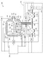
[0016] 図1は、炭化ホウ素層をドライストリッピングするためのバッチ処理圧力容器100の簡略正面断面図である。圧力容器100は、外面112と処理領域115を取り囲む内面113とを備えた本体110を有する。図1などのいくつかの実施形態では、本体110は環状断面を有するが、他の実施形態では、本体110の断面は矩形又は任意の閉鎖形状になりうる。本体110の外面112は、例えば限定するものではないが、ステンレス鋼などの耐食性鋼(CRS)から作られうる。本体110の内面113は、例えば限定するものではないが、HASTELLOY(登録商標)などの、高耐食性を示すニッケルベース鋼合金から作られうる。
[0016] Figure 1 is a simplified cross-sectional front view of a batch
[0017] 圧力容器100は、ドア120が開くと処理領域115にアクセス可能になり、本体110内に処理領域115を密閉可能に囲むように構成されたドア120を有する。密封材122は、処理のために処理領域115を密封するため、ドア120を本体110に密封するために利用される。密封材122は、例えば限定するものではないが、パーフルオロエラストマーなどのポリマーから作られうる。処理中に密封材122の最大安全動作温度未満に密封材122を維持するため、冷却チャネル124は、密封材122に隣接するドア120の上に配設される。冷却剤、例えば限定するものではないが、不活性物質、誘電体、及び/又は高性能な熱伝導流体などの冷却剤は、密封材122を約250°Cから約275°Cまでの温度に維持し、その一方で処理領域115が約800°Cになるように冷却チャネル124内で循環されうる。冷却チャネル124内の冷却剤の流れは、温度センサ116又は流れセンサ(図示せず)から受信したフィードバックを介して、コントローラ180によって制御される。
[0017] The
[0018] 圧力容器100は、本体110を通るポート117を有する。ポート117は、それ自体を通過してヒータ119に連結されるパイプ118を有する。パイプ118の一端は処理領域115に接続される。パイプ118の他端は、注入導管157と排出導管161に分岐する。注入導管157は、遮断バルブ155を介してガスパネル150に流体接続されている。注入導管157はヒータ158に連結されている。排出導管161は、遮断バルブ165を介して液化装置(condenser)160に流体接続されている。排出導管161はヒータ162に連結されている。ヒータ119、158、及び162は、パイプ118、注入導管157、及び排出導管161をそれぞれ通って流れる処理ガスを、処理ガスの凝結点を超える温度に維持するように構成されている。ヒータ119、158、及び162は、電源145によって電力供給される。
[0018]
[0019] ガスパネル150は、圧力下にある酸化剤を含む処理ガスを、パイプ118を経由して処理領域115へ伝送するため、注入導管157へ提供するように構成されている。処理領域115へ導入される処理ガスの圧力は、本体110に連結された圧力センサ114によってモニタされている。液化装置160は冷却流体に流体連結され、パイプ118を経由して処理領域115から除去された後に、排出導管161を通って流れる気体生成物を凝結するように構成されている。液化装置160は、気体生成物を気相から液相に変える。ポンプ170は液化装置160に流体連結され、液化装置160から液化生成物を排出する。ガスパネル150、液化装置160及びポンプ170の動作はコントローラ180によって制御されている。
[0019]
[0020] 遮断バルブ155及び165は、一度に1つの流体のみがパイプ118を経由して処理領域115に流れるように構成されている。遮断バルブ155が開いているとき、注入導管157を通って流れる処理ガスが処理領域115に入り、処理ガスの流れが液化装置160に入るのを防止するように、遮断バルブ165は閉じられている。その一方で、遮断バルブ165が開いているときには、気体生成物が処理領域115から除去され、排出導管161を通って流れ、気体生成物の流れがガスパネル150に入るのを防止するように、遮断バルブ155は閉じられている。
[0020]
[0021] 一又は複数のヒータ140は、本体110の上に配置され、圧力容器100内の処理領域115を加熱するように構成されている。いくつかの実施形態では、図1に示したように、ヒータ140は本体110の外面112の上に配置されるが、他の実施形態では、ヒータ140は本体110の内面113の上に配置されうる。ヒータ140の各々は、抵抗コイル、ランプ、セラミックヒータ、グラファイトベースの炭素繊維複合材(CFC)ヒータ、ステンレス鋼ヒータ、又はアルミニウムヒータなどになりうる。ヒータ140は、電源145によって電力供給される。ヒータ140への電力は、温度センサ116から受信したフィードバックを介してコントローラ180によって制御される。温度センサ116は本体110に連結され、処理領域115の温度をモニタする。
[0021] One or
[0022] アクチュエータ(図示せず)に連結されたカセット130は、処理領域115との間で出し入れされる。カセット130は、上面132、底面134、及び壁136を有する。カセット130の壁136は、複数の基板ストレージスロット138を有する。各基板ストレージスロット138は、カセット130の壁136に沿って均等に離間されている。各基板ストレージスロット138は、内部に基板135を保持するよう構成される。カセット130は、基板135を保持するための50個もの基板ストレージスロット138を有しうる。カセット130は、圧力容器100の内外へ複数の基板135を移送するための、また、処理領域115内で複数の基板135を処理するための、有効な容器を提供する。
[0022] A
[0023] コントローラ180は圧力容器100の動作を制御する。コントローラ180は、ガスパネル150、液化装置160、ポンプ170、遮断バルブ155及び165、並びに電源145の動作を制御する。コントローラ180はまた、温度センサ116、圧力センサ114、及び冷却チャネル124に連通可能に接続されている。コントローラ180は、中央処理装置(CPU)182、メモリ184、及び補助回路186を含む。CPU182は、産業用設定で使用されうる任意の形態の汎用コンピュータプロセッサでありうる。メモリ184は、ランダムアクセスメモリ、読取専用メモリ、フロッピー、又はハードディスクドライブ、又は他の形態のデジタルストレージになりうる。補助回路186は、通常、CPU182に接続され、キャッシュ、クロック回路、入力/出力システム、電源などを含みうる。
[0023] A
[0024] 圧力容器100は、複数の基板135から炭化ホウ素層をドライストリッピングする方法を実行するのに便利なチャンバを提供する。ヒータ140は、圧力容器100を予加熱するため、電力供給される。同時に、ヒータ119、158、及び162は、パイプ118、注入導管157、及び排出導管161をそれぞれ予加熱するため、電力供給される。
[0024]
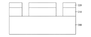
[0025] 複数の基板135は次に、カセット130に装填される。図2Aは、半導体基板200上のエッチングされた層210の上にパターニングされた炭化ホウ素層220の簡略断面図を示す。基板135がカセット130に装填されると、基板135の各々は、図2Aに半導体基板200として示されている。カセット130を処理領域115へ移動するため、圧力容器100のドア120は開放される。カセット130上の基板135の上部から炭化ホウ素層をストリッピングするため、ドア120はチャンバを取り囲むように密封される。ドア120が一旦閉じられると、処理領域115から圧力が漏れないことが密封材122によって保証される。
A plurality of
[0026] 処理ガスは、ガスパネル150によって、圧力容器100内部の処理領域115に提供される。遮断バルブ155はコントローラ180によって開放され、処理ガスは注入導管157及びパイプ118を経由して処理領域115に流れ込むことができる。処理ガスは、約1分間から約2時間の間、約500sccmから約2000sccmの流量で導入される。遮断バルブ165はこの時点では閉じられたままになっている。処理ガスは処理領域115に流れ込んだ酸化剤である。いくつかの実施形態では、処理ガスは、約500Torrから約60barまでの圧力下において蒸気であり、乾燥蒸気又は過熱蒸気であってもよい。しかしながら、他の実施形態では、例えば限定するものではないが、オゾン、酸素、過酸化水素又はアンモニアなどの他の酸化剤が使用されうる。一実施形態では、処理ガスは、約5%の蒸気から100%の酸化剤、例えば、約10%の酸化剤から約80%の酸化剤を含む混合物である。一実施例では、処理ガスは約5%の蒸気から100%の蒸気までの混合物である。充分な処理ガスがガスパネル150によって放出されると、遮断バルブ155はコントローラ180によって閉じられる。ガスパネル150による処理ガスの量は、複数の基板135上に堆積した炭化ホウ素と完全に反応するのに必要な処理ガスの量を超える量になっている。例えば、ガスパネル150によって放出される蒸気の量は、基板上に堆積した炭化ホウ素の量の少なくとも10倍になりうる。
[0026] Process gases are provided to the
[0027] 基板135の処理中、処理領域115、並びに注入導管157、排出導管161、及びパイプ118は、処理ガスが気相に留まる温度と圧力に維持される。このような圧力と温度は、処理ガスの組成に基づいて選択される。処理領域115、並びに注入導管157、排出導管161、及びパイプ118の温度は、印加された圧力で処理ガスの凝結点を超える温度に維持される。例えば、10barsから60barsの圧力下で蒸気が処理に使用されるときには、処理領域115、並びに注入導管157、排出導管161、及びパイプ118の温度は、約300°Cから700°Cの温度まで高められる。これにより、エッチングされた層210及び層220の下の基板200に対して有害な水へと、蒸気が凝結しないことが保証される。
[0027] During processing of
[0028] 炭化ホウ素層が処理ガスと反応して気体生成物を産生するように、処理ガスは基板135の上に流される。例えば、炭化ホウ素は、化学反応式(i)及び(ii)に示したように、蒸気と反応して、三酸化ホウ素(B2O3)、水素ガス(H2)、一酸化炭素(CO)、及び二酸化炭素(CO2)を産生する。
2BC + 5H2O → B2O3 + 2CO + 5H2 ………(i)
2BC + 7H2O → B2O3 + 2CO2 + 7H2 ……(ii)
三酸化ホウ素(B2O3)は次に過剰な蒸気と反応して、化学反応式(iii)及び(iv)に示したように、ホウ酸(H3BO3)及びメタホウ酸(HBO2)を産生する。
B2O3 + H2O → 2HBO2 …………………………… (iii)
B2O3 + 3H2O → 2H3BO3 ………………………… (iv)
ホウ酸及びメタホウ酸は揮発性の生成物である。ホウ酸及びメタホウ酸は水素ガス、一酸化炭素及び二酸化炭素と混合して、炭化ホウ素と水蒸気との間の反応生成物の気体混合物を形成する。
[0028] A process gas is flowed over the
2BC + 5H2O → B2O3 + 2CO + 5H2 ( i)
2BC + 7H2O → B2O3 + 2CO2 + 7H2 ( ii )
Boron trioxide (B 2 O 3 ) then reacts with excess steam to form boric acid (H 3 BO 3 ) and metaboric acid (HBO 2 ) as shown in chemical equations (iii) and (iv). ).
B2O3 + H2O → 2HBO2 ( iii )
B 2 O 3 + 3H 2 O → 2H 3 BO 3 ………………………… (iv)
Boric acid and metaboric acid are volatile products. Boric acid and metaboric acid are mixed with hydrogen gas, carbon monoxide and carbon dioxide to form a gaseous mixture of reaction products between boron carbide and water vapor.
[0029] 炭化ホウ素層が基板135から完全にストリッピングされたことが認められると、処理は完了する。次に、生成物の気体混合物を処理領域115から、パイプ118と排出導管161を経由して液化装置160へ流し込むため、遮断バルブ165が開放される。生成物の気体混合物は、液化装置160内で液相に凝結される。生成物の液化混合物は次に、ポンプ170によって除去される。生成物の液化混合物が完全に除去されると、遮断バルブ165は閉鎖される。次に、ヒータ140、119、158、及び162の電源がオフにされる。次に、処理領域115からカセット130を取り出すため、圧力容器100のドア120が開放される。図2Bは、炭化ホウ素層を除去した後の、半導体基板200上のエッチング層210の簡略断面図である。炭化ホウ素層を除去した後、基板135がカセット130から取り出されると、基板135の各々は、図2Bに半導体基板200として示されている。基板135は、パターニングされたエッチング層210のみを有する。
[0029] Once the boron carbide layer is found to be completely stripped from the
[0030] 図3は、炭化ホウ素層をドライストリッピングするための1つの基板処理チャンバ300の簡略正面断面図である。1つの基板処理チャンバ300は、外面312と内部空間315を取り囲む内面313とを備える本体310を有する。図3などのいくつかの実施形態では、本体310は環状断面を有するが、他の実施形態では、本体310の断面は矩形又は任意の閉鎖形状になりうる。本体310の外面312は、例えば限定するものではないが、ステンレス鋼などの耐食性鋼(CRS)から作られうる。1つの基板処理チャンバ300から外部環境への熱損失を防止する一又は複数の熱シールド325が、本体310の内面313上に配置される。本体310の内面313、並びに熱シールド325は、例えば限定するものではないが、HASTELLOY(登録商標)、INCONEL(登録商標)、及びMONEL(登録商標)など、高い耐食性を示すニッケルベースの鋼合金から作られうる。
[0030] Figure 3 is a simplified front cross-sectional view of one
[0031] 基板支持体330が、内部空間315内に配置される。基板支持体330は、ステム334と、ステム334によって保持される基板支持部材332とを有する。ステム334は、チャンバ本体310を通って形成された通路322を通過する。アクチュエータ338に接続されたロッド339は、チャンバ本体310を通って形成された第2の通路323を通過する。ロッド339は、基板支持体330のステム334を収容する開口部336を有するプレート335に連結されている。リフトピン337は、基板支持部材332に接続されている。プレート335が上下に移動してリフトピン337との接続と分離を行うように、アクチュエータ338はロッド339を作動させる。リフトピン337が上げ下げされると、基板支持部材332は1つの基板処理チャンバ300の内部空間315内で上げ下げされる。基板支持部材332は、中心に埋め込まれた抵抗加熱素子331を有する。電源333は、抵抗加熱素子331に電力を供給するように構成されている。電源333並びにアクチュエータ338の操作はコントローラ380によって制御される。
[0031] A
[0032] 1つの基板処理チャンバ300は本体310に開口部311を有し、基板320はその開口部を通り、内部空間315内に配置された基板支持体330との間で出し入れされる。開口部311は、本体310にトンネル321を形成する。スリットバルブ328が開放されているときにのみ、開口部311と内部空間315がアクセス可能になるように、スリットバルブ328はトンネル321を密封するように構成されている。密封材327は、処理のための内部空間315を密封するため、スリットバルブ328を本体310に密封するように利用される。密封材327はポリマーから、例えば限定するものではないが、パーフルオロエラストマーやポリテトラフルオロエチレン(PTFE)などのフルオロポリマーから作られうる。密封材327はさらに、密封性能を高めるため、密封材を付勢するためのばね部材を含みうる。処理中に密封材327の最大安全動作温度未満に密封材327を維持するため、冷却チャネル324は、密封材327に隣接するトンネル321の上に配設される。冷却流体源326からの冷却剤、例えば限定するものではないが、不活性物質、誘電体、及び/又は高性能な熱伝導流体などは、冷却チャネル324内で循環されうる。冷却流体源326からの冷却源の流れは、温度センサ316又は流れセンサ(図示せず)から受信したフィードバックを介して、コントローラ380によって制御される。スリットバルブ328が開放されているとき、内部空間315から開口部311を通る熱の流れを妨げるため、環状形状の熱チョーク329がトンネル321の周囲に形成される。
[0032] One
[0033] 1つの基板処理チャンバ300は本体310を通るポート317を有し、これは、ガスパネル350、液化装置360、及びポート317を接続する流体回路390に流体接続されている。流体回路390は、ガス導管392、ソース導管357、注入遮断バルブ355、排気導管363、及び排出遮断バルブ365を有する。多数のヒータ396、358、352、354、364、366が流体回路390の様々な部分にインターフェースされている。温度測定を行い、その情報をコントローラ380に送るため、多数の温度センサ351、353、319、367、及び369がまた、流体回路390の様々な部分に配置されている。流体回路390の温度が、流体回路390及び内部空間315内に配置された処理流体の凝結点を超える温度に維持されるように、コントローラ380は、ヒータ352、354、358、396、364、及び366の動作を制御するため、温度測定情報を使用する。
[0033] One
[0034] ガスパネル350及び圧力センサ314は、本質的にも機能的にも図1のガスパネル150及び圧力センサ114とほぼ同様である。液化装置360は、本質的にも機能的にも図1の液化装置160とほぼ同様である。ポンプ370は、本質的にも機能的にも図1のポンプ170とほぼ同様である。一又は複数のヒータ340は本体310の上に配置され、1つの基板処理チャンバ300内の内部空間315を加熱するように構成されている。ヒータ340は、本質的にも機能的にもバッチ処理圧力容器100内で使用されるヒータ140とほぼ同様である。
[0034]
[0035] コントローラ380は、1つの基板処理チャンバ300の動作を制御する。コントローラ380は、ガスパネル350、液化装置360、ポンプ370、注入遮断バルブ355、排出遮断バルブ365、及び電源333、345の動作を制御する。コントローラ380はまた、温度センサ316、圧力センサ314、アクチュエータ338、冷却流体源326、及び温度読取デバイス356と362に通信可能に接続されている。コントローラ380は、本質的にも機能的にもバッチ処理圧力容器100内で使用されるコントローラ180とほぼ同様である。
[0035] A
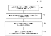
[0036] 図4は、本開示の一実施形態による、半導体基板上に堆積した炭化ホウ素層をドライストリッピングするための方法のブロック図である。方法400は、ブロック410で基板を圧力容器に装填することによって開始される。基板は上部に堆積した炭化ホウ素層を有する。いくつかの実施形態では、複数の基板はカセットの上に配置され、圧力容器内に装填されうる。さらなる実施形態では、一度に1つの基板を処理するように構成された圧力容器に1つの基板が装填される。
[0036] Figure 4 is a block diagram of a method for dry stripping a boron carbide layer deposited on a semiconductor substrate, according to one embodiment of the present disclosure.
[0037] ブロック420では、基板又は複数の基板は、圧力容器内で約500Torrから約60barの圧力で、酸化剤を含む処理ガスに曝露される。他の実施形態では、基板又は複数の基板は、圧力容器内で約0barを超える圧力で、例えば約1barから約60barの圧力で、酸化剤を含む処理ガスに曝露される。いくつかの実施形態では、処理ガスは、オゾン、酸素、水蒸気、重水、過酸化物、水酸化物含有化合物、酸素同位体(14、15、16、17、18など)及び水素同位体(1、2、3)、或いはこれらのいくつかの組み合わせからなる群から選択された酸化剤で、処理ガスは約10%の酸化剤から約80%の酸化剤の混合物である。過酸化物は気相にある過酸化水素であってもよい。いくつかの実施形態では、酸化剤は、例えば限定するものではないが、水蒸気又は蒸気の形態の重水など、水酸化物イオンを含む。いくつかの実施形態では、酸化剤の量は、基板上に堆積した炭化ホウ素の量と完全に反応するのに必要な酸化剤の量を超える。他の実施形態では、処理ガスは約500Torrから約60barまでの圧力の蒸気であってよく、蒸気は混合物の約5%から混合物の100%までを構成する。蒸気は乾燥蒸気又は過熱蒸気であってもよい。蒸気の量は、基板上に堆積した炭化ホウ素の量の少なくとも10倍になりうる。
[0037] At
[0038] ブロック430では、圧力容器は、処理ガスの凝結点を超える温度まで加熱される。温度を上げることにより、炭化ホウ素層を処理ガスと反応させることができる。いくつかの実施形態では、蒸気が圧力容器内の処理ガスとして使用されるときには、圧力容器の温度は約300°Cから約700°Cに維持される。これらの実施形態では、炭化ホウ素層は蒸気と反応して、三酸化ホウ素、二酸化炭素、一酸化炭素、水素、ホウ酸及びメタホウ酸を含む気体混合物を生成する。
[0038] At
[0039] ブロック440では、処理ガスと炭化ホウ素層との間の一又は複数の反応生成物が圧力容器から除去される。蒸気が使用される実施形態では、三酸化ホウ素、二酸化炭素、一酸化炭素、水素、ホウ酸、及びメタホウ酸を含む生成物の気体混合物は、圧力容器の外へ排出される。したがって、基板上の炭化ホウ素層はドライストリッピングされ、半導体基板上に好適なエッチング層が残される。
[0039] At
[0040] 本書に記載の炭化ホウ素層をドライストリッピングするための方法は有利には、半導体基板から炭化ホウ素層を乾式除去することができる。湿式エッチングソリューションは要求されない。さらに、圧力下で蒸気が使用されるときには、約300°Cから約700°Cの処理温度範囲によって、炭化ホウ素の酸化速度は、最初に炭化ホウ素を三酸化ホウ素の粘性層に変換するのには十分に低く、三酸化ホウ素の粘性層を、その後除去しうるホウ酸やメタホウ酸のような揮発性ガスに変換するのには十分に高いことが保証される。処理温度が300°C未満、或いは処理圧力が500Torr未満の場合には、炭化ホウ素から三酸化ホウ素への最初の酸化と、三酸化ホウ素からホウ酸及びメタホウ酸へのその後の酸化とのバランスは失われ、その結果、層は完全にストリッピングすることができない。 [0040] The methods for dry stripping a boron carbide layer described herein can advantageously dry remove a boron carbide layer from a semiconductor substrate. No wet etching solution is required. Further, when steam under pressure is used, the process temperature range of about 300° C. to about 700° C. causes the boron carbide oxidation rate to be is low enough to ensure that the viscous layer of boron trioxide is converted to volatile gases such as boric acid and metaboric acid that can then be removed. When the processing temperature is less than 300°C or the processing pressure is less than 500 Torr, the balance between the initial oxidation of boron carbide to boron trioxide and the subsequent oxidation of boron trioxide to boric acid and metaboric acid is is lost and as a result the layer cannot be completely stripped.
[0041] 本書に記載の方法は、複数の基板を同時に処理することによって、炭化ホウ素層の除去に関して基板のスループットを高める。しかも、他の層を除去しうる従来の酸素プラズマでは炭化ホウ素を灰化することができないため、本方法によって、炭化ホウ素のハードマスク材料としての実行可能性は維持される。炭化ホウ素の高いエッチング選択性、高い硬度及び高い透明性により、炭化ホウ素はハードマスク材料として優れた選択肢になっている。したがって、本書に記載の方法は、次世代のメモリデバイス、論理デバイス、マイクロプロセッサなどをパターニングするため、炭化ホウ素層をさらに開発する際に役立つ。加えて、本書に記載の方法は炭化ホウ素層に関するが、他の種類の炭化ホウ素層も本開示から利益を得ることができる。 [0041] The methods described herein increase substrate throughput for removal of boron carbide layers by processing multiple substrates simultaneously. Moreover, the method maintains the viability of boron carbide as a hard mask material, since boron carbide cannot be ashed in conventional oxygen plasmas that can remove other layers. Boron carbide's high etch selectivity, high hardness, and high transparency make it an excellent choice as a hardmask material. Accordingly, the methods described herein are useful in further developing boron carbide layers for patterning next generation memory devices, logic devices, microprocessors, and the like. Additionally, while the methods described herein relate to boron carbide layers, other types of boron carbide layers can also benefit from the present disclosure.
[0042] 以上の記述は本開示の特定の実施形態を対象としているが、これらの実施形態は本発明の原理及び用途の例示にすぎないことを、理解されたい。したがって、添付の特許請求の範囲によって定義されているように、本発明の基本的な主旨及び範囲から逸脱することなく、他の実施形態に到達する例示的な実施形態になりうる多数の修正を行いうることを理解されたい。 [0042] While the above description is directed to specific embodiments of the disclosure, it is to be understood that these embodiments are merely illustrative of the principles and applications of the invention. Accordingly, numerous modifications may be made to the exemplary embodiments to arrive at other embodiments without departing from the basic spirit and scope of the invention as defined by the appended claims. It should be understood that it can be done.
Claims (18)
前記炭化ホウ素層が上部に堆積している前記基板を圧力容器の処理領域に装填することと、
500Torrから60barの圧力で、酸化剤を含む処理ガスであって、プラズマを含まない処理ガスに前記基板を曝露することと、
前記処理ガスの凝結点を超える温度まで前記圧力容器の前記処理領域を加熱することと、
前記処理ガスと前記炭化ホウ素層との間の一又は複数の反応生成物を前記圧力容器から除去することと、
を含む方法。 A method for stripping a layer of boron carbide deposited on a substrate, comprising:
loading the substrate with the boron carbide layer deposited thereon into a processing region of a pressure vessel;
exposing the substrate to an oxidant-containing process gas, the plasma-free process gas at a pressure of 500 Torr to 60 bar;
heating the process region of the pressure vessel to a temperature above the condensation point of the process gas;
removing one or more reaction products between the process gas and the boron carbide layer from the pressure vessel;
method including.
前記基板を10barを超える圧力で蒸気に曝露することを含む、請求項1に記載の方法。 exposing the substrate to the process gas comprises:
2. The method of claim 1, comprising exposing the substrate to vapor at a pressure greater than 10 bar.
上部に堆積した前記炭化ホウ素層をそれぞれ有する前記複数の基板を、圧力容器の処理領域に同時に装填することと、
500Torrから60barの圧力で、酸化剤を含む処理ガスに前記複数の基板を曝露することと、
前記処理ガスの凝結点を超える温度まで前記圧力容器の前記処理領域を加熱することと、
前記処理ガスと前記炭化ホウ素層との間の一又は複数の反応生成物を前記圧力容器から除去することと、
を含む方法。 A method of stripping a layer of boron carbide deposited on a plurality of substrates, comprising:
simultaneously loading the plurality of substrates, each having the boron carbide layer deposited thereon, into a processing region of a pressure vessel;
exposing the plurality of substrates to a process gas comprising an oxidant at a pressure of 500 Torr to 60 bar;
heating the process region of the pressure vessel to a temperature above the condensation point of the process gas;
removing one or more reaction products between the process gas and the boron carbide layer from the pressure vessel;
method including.
前記複数の基板を10barを超える圧力で蒸気に曝露することを含む、請求項7に記載の方法。 exposing the plurality of substrates to the process gas comprises:
8. The method of claim 7 , comprising exposing the plurality of substrates to vapor at a pressure greater than 10 bar.
上部に堆積した前記炭化ホウ素層をそれぞれ有する前記複数の基板を、圧力容器の処理領域に同時に装填することと、
10barから60barの圧力で、蒸気を含む処理ガスに前記複数の基板を曝露することと、
前記処理ガスの凝結点を超える温度まで前記圧力容器の前記処理領域を加熱することと、
前記処理ガスと前記炭化ホウ素層との間の一又は複数の反応生成物を前記圧力容器から除去することと、
を含む方法。 A method of stripping a layer of boron carbide deposited on a plurality of substrates, comprising:
simultaneously loading the plurality of substrates, each having the boron carbide layer deposited thereon, into a processing region of a pressure vessel;
exposing the plurality of substrates to a process gas comprising vapor at a pressure of 10 bar to 60 bar;
heating the process region of the pressure vessel to a temperature above the condensation point of the process gas;
removing one or more reaction products between the process gas and the boron carbide layer from the pressure vessel;
method including.
Applications Claiming Priority (5)
| Application Number | Priority Date | Filing Date | Title |
|---|---|---|---|
| US201762514554P | 2017-06-02 | 2017-06-02 | |
| US62/514,554 | 2017-06-02 | ||
| US201862648073P | 2018-03-26 | 2018-03-26 | |
| US62/648,073 | 2018-03-26 | ||
| PCT/US2018/035210 WO2018222771A1 (en) | 2017-06-02 | 2018-05-30 | Dry stripping of boron carbide hardmask |
Publications (3)
| Publication Number | Publication Date |
|---|---|
| JP2020522882A JP2020522882A (en) | 2020-07-30 |
| JP2020522882A5 JP2020522882A5 (en) | 2021-07-26 |
| JP7190450B2 true JP7190450B2 (en) | 2022-12-15 |
Family
ID=64455587
Family Applications (1)
| Application Number | Title | Priority Date | Filing Date |
|---|---|---|---|
| JP2019564959A Active JP7190450B2 (en) | 2017-06-02 | 2018-05-30 | Dry stripping of boron carbide hardmask |
Country Status (6)
| Country | Link |
|---|---|
| US (1) | US10529585B2 (en) |
| JP (1) | JP7190450B2 (en) |
| KR (1) | KR102574914B1 (en) |
| CN (1) | CN110678973B (en) |
| TW (1) | TWI763858B (en) |
| WO (1) | WO2018222771A1 (en) |
Families Citing this family (16)
| Publication number | Priority date | Publication date | Assignee | Title |
|---|---|---|---|---|
| US10622214B2 (en) | 2017-05-25 | 2020-04-14 | Applied Materials, Inc. | Tungsten defluorination by high pressure treatment |
| US10276411B2 (en) | 2017-08-18 | 2019-04-30 | Applied Materials, Inc. | High pressure and high temperature anneal chamber |
| WO2019036157A1 (en) | 2017-08-18 | 2019-02-21 | Applied Materials, Inc. | High pressure and high temperature anneal chamber |
| JP7274461B2 (en) | 2017-09-12 | 2023-05-16 | アプライド マテリアルズ インコーポレイテッド | Apparatus and method for manufacturing semiconductor structures using protective barrier layers |
| SG11202003355QA (en) | 2017-11-11 | 2020-05-28 | Micromaterials Llc | Gas delivery system for high pressure processing chamber |
| JP2021503714A (en) | 2017-11-17 | 2021-02-12 | アプライド マテリアルズ インコーポレイテッドApplied Materials,Incorporated | Capacitor system for high pressure processing system |
| EP3762962A4 (en) | 2018-03-09 | 2021-12-08 | Applied Materials, Inc. | High pressure annealing process for metal containing materials |
| US10950429B2 (en) | 2018-05-08 | 2021-03-16 | Applied Materials, Inc. | Methods of forming amorphous carbon hard mask layers and hard mask layers formed therefrom |
| US11689080B2 (en) * | 2018-07-09 | 2023-06-27 | Siemens Energy, Inc. | Supercritical CO2 cooled electrical machine |
| US10748783B2 (en) | 2018-07-25 | 2020-08-18 | Applied Materials, Inc. | Gas delivery module |
| WO2020117462A1 (en) | 2018-12-07 | 2020-06-11 | Applied Materials, Inc. | Semiconductor processing system |
| CN113130384A (en) * | 2020-01-16 | 2021-07-16 | 中芯国际集成电路制造(天津)有限公司 | Method for forming semiconductor structure |
| US11901222B2 (en) | 2020-02-17 | 2024-02-13 | Applied Materials, Inc. | Multi-step process for flowable gap-fill film |
| US11600507B2 (en) * | 2020-09-09 | 2023-03-07 | Applied Materials, Inc. | Pedestal assembly for a substrate processing chamber |
| US20220230887A1 (en) * | 2021-01-15 | 2022-07-21 | Applied Materials, Inc. | Methods and apparatus for processing a substrate |
| KR20240053429A (en) * | 2022-10-17 | 2024-04-24 | 피에스케이 주식회사 | Apparatus for treating substrate and method for treating a substrate |
Citations (4)
| Publication number | Priority date | Publication date | Assignee | Title |
|---|---|---|---|---|
| JP2009515366A (en) | 2005-11-08 | 2009-04-09 | 東京エレクトロン株式会社 | Batch photoresist dry stripping and ashing system and method |
| JP2014516205A (en) | 2011-05-12 | 2014-07-07 | アプライド マテリアルズ インコーポレイテッド | Method for dry stripping boron carbon films |
| US20140216498A1 (en) | 2013-02-06 | 2014-08-07 | Kwangduk Douglas Lee | Methods of dry stripping boron-carbon films |
| JP2018511166A (en) | 2015-04-02 | 2018-04-19 | アプライド マテリアルズ インコーポレイテッドApplied Materials,Incorporated | Mask etching for patterning |
Family Cites Families (200)
| Publication number | Priority date | Publication date | Assignee | Title |
|---|---|---|---|---|
| US4524587A (en) | 1967-01-10 | 1985-06-25 | Kantor Frederick W | Rotary thermodynamic apparatus and method |
| JPH0748489B2 (en) | 1987-07-27 | 1995-05-24 | 富士通株式会社 | Plasma processing device |
| US5114513A (en) | 1988-10-27 | 1992-05-19 | Omron Tateisi Electronics Co. | Optical device and manufacturing method thereof |
| JP2730695B2 (en) | 1989-04-10 | 1998-03-25 | 忠弘 大見 | Tungsten film forming equipment |
| US5175123A (en) | 1990-11-13 | 1992-12-29 | Motorola, Inc. | High-pressure polysilicon encapsulated localized oxidation of silicon |
| US5050540A (en) | 1991-01-29 | 1991-09-24 | Arne Lindberg | Method of gas blanketing a boiler |
| JPH05139870A (en) * | 1991-11-25 | 1993-06-08 | Hitachi Chem Co Ltd | Boron carbide-coated carbon material |
| US5319212A (en) | 1992-10-07 | 1994-06-07 | Genus, Inc. | Method of monitoring ion beam current in ion implantation apparatus for use in manufacturing semiconductors |
| US5607002A (en) | 1993-04-28 | 1997-03-04 | Advanced Delivery & Chemical Systems, Inc. | Chemical refill system for high purity chemicals |
| JPH0733565A (en) * | 1993-07-20 | 1995-02-03 | Toyo Tanso Kk | Carbon material coated with boron carbide and its production |
| US5880041A (en) | 1994-05-27 | 1999-03-09 | Motorola Inc. | Method for forming a dielectric layer using high pressure |
| US5620524A (en) | 1995-02-27 | 1997-04-15 | Fan; Chiko | Apparatus for fluid delivery in chemical vapor deposition systems |
| KR100251341B1 (en) | 1995-05-08 | 2000-05-01 | 오카노 사다오 | Optical waveguide manufacturing method |
| US5895274A (en) | 1996-01-22 | 1999-04-20 | Micron Technology, Inc. | High-pressure anneal process for integrated circuits |
| KR980012044A (en) | 1996-03-01 | 1998-04-30 | 히가시 데츠로 | Substrate drying apparatus and substrate drying method |
| US5998305A (en) * | 1996-03-29 | 1999-12-07 | Praxair Technology, Inc. | Removal of carbon from substrate surfaces |
| US5738915A (en) | 1996-09-19 | 1998-04-14 | Lambda Technologies, Inc. | Curing polymer layers on semiconductor substrates using variable frequency microwave energy |
| US6444037B1 (en) | 1996-11-13 | 2002-09-03 | Applied Materials, Inc. | Chamber liner for high temperature processing chamber |
| US6082950A (en) | 1996-11-18 | 2000-07-04 | Applied Materials, Inc. | Front end wafer staging with wafer cassette turntables and on-the-fly wafer center finding |
| US6136664A (en) | 1997-08-07 | 2000-10-24 | International Business Machines Corporation | Filling of high aspect ratio trench isolation |
| US5963817A (en) | 1997-10-16 | 1999-10-05 | International Business Machines Corporation | Bulk and strained silicon on insulator using local selective oxidation |
| JP3199006B2 (en) | 1997-11-18 | 2001-08-13 | 日本電気株式会社 | Method of forming interlayer insulating film and insulating film forming apparatus |
| US6442980B2 (en) | 1997-11-26 | 2002-09-03 | Chart Inc. | Carbon dioxide dry cleaning system |
| JPH11171669A (en) * | 1997-12-15 | 1999-06-29 | Ngk Insulators Ltd | Production of boron carbide film |
| US6846739B1 (en) | 1998-02-27 | 2005-01-25 | Micron Technology, Inc. | MOCVD process using ozone as a reactant to deposit a metal oxide barrier layer |
| US6719516B2 (en) | 1998-09-28 | 2004-04-13 | Applied Materials, Inc. | Single wafer load lock with internal wafer transport |
| US20030101938A1 (en) | 1998-10-27 | 2003-06-05 | Applied Materials, Inc. | Apparatus for the deposition of high dielectric constant films |
| US6334266B1 (en) | 1999-09-20 | 2002-01-01 | S.C. Fluids, Inc. | Supercritical fluid drying system and method of use |
| US6612317B2 (en) | 2000-04-18 | 2003-09-02 | S.C. Fluids, Inc | Supercritical fluid delivery and recovery system for semiconductor wafer processing |
| DE69940114D1 (en) | 1999-08-17 | 2009-01-29 | Applied Materials Inc | Surface treatment of carbon-doped SiO 2 films to increase the stability during O 2 ashing |
| US6299753B1 (en) | 1999-09-01 | 2001-10-09 | Applied Materials, Inc. | Double pressure vessel chemical dispenser unit |
| US6500603B1 (en) | 1999-11-11 | 2002-12-31 | Mitsui Chemicals, Inc. | Method for manufacturing polymer optical waveguide |
| US6150286A (en) | 2000-01-03 | 2000-11-21 | Advanced Micro Devices, Inc. | Method of making an ultra thin silicon nitride film |
| US6541367B1 (en) | 2000-01-18 | 2003-04-01 | Applied Materials, Inc. | Very low dielectric constant plasma-enhanced CVD films |
| US6319766B1 (en) | 2000-02-22 | 2001-11-20 | Applied Materials, Inc. | Method of tantalum nitride deposition by tantalum oxide densification |
| JP2001250787A (en) | 2000-03-06 | 2001-09-14 | Hitachi Kokusai Electric Inc | Equipment and method for treating substrate |
| US20040025908A1 (en) | 2000-04-18 | 2004-02-12 | Stephen Douglas | Supercritical fluid delivery system for semiconductor wafer processing |
| US7166524B2 (en) | 2000-08-11 | 2007-01-23 | Applied Materials, Inc. | Method for ion implanting insulator material to reduce dielectric constant |
| US6852167B2 (en) | 2001-03-01 | 2005-02-08 | Micron Technology, Inc. | Methods, systems, and apparatus for uniform chemical-vapor depositions |
| US6797336B2 (en) | 2001-03-22 | 2004-09-28 | Ambp Tech Corporation | Multi-component substances and processes for preparation thereof |
| TW544797B (en) | 2001-04-17 | 2003-08-01 | Kobe Steel Ltd | High-pressure processing apparatus |
| US7080651B2 (en) | 2001-05-17 | 2006-07-25 | Dainippon Screen Mfg. Co., Ltd. | High pressure processing apparatus and method |
| EP1271636A1 (en) | 2001-06-22 | 2003-01-02 | Infineon Technologies AG | Thermal oxidation process control by controlling oxidation agent partial pressure |
| US6781801B2 (en) | 2001-08-10 | 2004-08-24 | Seagate Technology Llc | Tunneling magnetoresistive sensor with spin polarized current injection |
| US6619304B2 (en) | 2001-09-13 | 2003-09-16 | Micell Technologies, Inc. | Pressure chamber assembly including non-mechanical drive means |
| US20030098069A1 (en) | 2001-11-26 | 2003-05-29 | Sund Wesley E. | High purity fluid delivery system |
| US6848458B1 (en) | 2002-02-05 | 2005-02-01 | Novellus Systems, Inc. | Apparatus and methods for processing semiconductor substrates using supercritical fluids |
| US6632325B2 (en) | 2002-02-07 | 2003-10-14 | Applied Materials, Inc. | Article for use in a semiconductor processing chamber and method of fabricating same |
| US7589029B2 (en) * | 2002-05-02 | 2009-09-15 | Micron Technology, Inc. | Atomic layer deposition and conversion |
| US7638727B2 (en) | 2002-05-08 | 2009-12-29 | Btu International Inc. | Plasma-assisted heat treatment |
| US7521089B2 (en) | 2002-06-13 | 2009-04-21 | Tokyo Electron Limited | Method and apparatus for controlling the movement of CVD reaction byproduct gases to adjacent process chambers |
| US20070243317A1 (en) | 2002-07-15 | 2007-10-18 | Du Bois Dale R | Thermal Processing System and Configurable Vertical Chamber |
| US7335609B2 (en) | 2004-08-27 | 2008-02-26 | Applied Materials, Inc. | Gap-fill depositions introducing hydroxyl-containing precursors in the formation of silicon containing dielectric materials |
| US20070212850A1 (en) | 2002-09-19 | 2007-09-13 | Applied Materials, Inc. | Gap-fill depositions in the formation of silicon containing dielectric materials |
| JP2004127958A (en) | 2002-09-30 | 2004-04-22 | Kyoshin Engineering:Kk | Apparatus and method for performing high pressure anneal steam treatment |
| US20040060519A1 (en) | 2002-10-01 | 2004-04-01 | Seh America Inc. | Quartz to quartz seal using expanded PTFE gasket material |
| US6889508B2 (en) | 2002-10-02 | 2005-05-10 | The Boc Group, Inc. | High pressure CO2 purification and supply system |
| US20040112409A1 (en) | 2002-12-16 | 2004-06-17 | Supercritical Sysems, Inc. | Fluoride in supercritical fluid for photoresist and residue removal |
| US7658973B2 (en) | 2003-02-04 | 2010-02-09 | Applied Materials, Inc. | Tailoring nitrogen profile in silicon oxynitride using rapid thermal annealing with ammonia under ultra-low pressure |
| JP3956049B2 (en) | 2003-03-07 | 2007-08-08 | 東京エレクトロン株式会社 | Method for forming tungsten film |
| US6939794B2 (en) | 2003-06-17 | 2005-09-06 | Micron Technology, Inc. | Boron-doped amorphous carbon film for use as a hard etch mask during the formation of a semiconductor device |
| US20070012402A1 (en) | 2003-07-08 | 2007-01-18 | Sundew Technologies, Llc | Apparatus and method for downstream pressure control and sub-atmospheric reactive gas abatement |
| JP4173781B2 (en) | 2003-08-13 | 2008-10-29 | 株式会社神戸製鋼所 | High pressure processing method |
| US7158221B2 (en) | 2003-12-23 | 2007-01-02 | Applied Materials, Inc. | Method and apparatus for performing limited area spectral analysis |
| US20050136684A1 (en) | 2003-12-23 | 2005-06-23 | Applied Materials, Inc. | Gap-fill techniques |
| US20050250347A1 (en) | 2003-12-31 | 2005-11-10 | Bailey Christopher M | Method and apparatus for maintaining by-product volatility in deposition process |
| US7030468B2 (en) | 2004-01-16 | 2006-04-18 | International Business Machines Corporation | Low k and ultra low k SiCOH dielectric films and methods to form the same |
| US20050187647A1 (en) | 2004-02-19 | 2005-08-25 | Kuo-Hua Wang | Intelligent full automation controlled flow for a semiconductor furnace tool |
| JP4393268B2 (en) | 2004-05-20 | 2010-01-06 | 株式会社神戸製鋼所 | Drying method of fine structure |
| US20050269291A1 (en) | 2004-06-04 | 2005-12-08 | Tokyo Electron Limited | Method of operating a processing system for treating a substrate |
| US7521378B2 (en) | 2004-07-01 | 2009-04-21 | Micron Technology, Inc. | Low temperature process for polysilazane oxidation/densification |
| US7491658B2 (en) | 2004-10-13 | 2009-02-17 | International Business Machines Corporation | Ultra low k plasma enhanced chemical vapor deposition processes using a single bifunctional precursor containing both a SiCOH matrix functionality and organic porogen functionality |
| WO2006055984A2 (en) | 2004-11-22 | 2006-05-26 | Applied Materials, Inc. | Substrate processing apparatus using a batch processing chamber |
| CN101128622B (en) | 2005-02-22 | 2010-08-25 | 埃克提斯公司 | Etching chamber with subchamber |
| WO2006101315A1 (en) | 2005-03-21 | 2006-09-28 | Pkl Co., Ltd. | Device and method for cleaning photomask |
| US20060226117A1 (en) | 2005-03-29 | 2006-10-12 | Bertram Ronald T | Phase change based heating element system and method |
| US20120060868A1 (en) | 2005-06-07 | 2012-03-15 | Donald Gray | Microscale fluid delivery system |
| ES2317159T3 (en) | 2005-06-10 | 2009-04-16 | Obducat Ab | MODEL REPLICATION WITH INTERMEDIATE SEAL. |
| JP4747693B2 (en) | 2005-06-28 | 2011-08-17 | 住友電気工業株式会社 | Method for forming resin body, method for forming structure for optical waveguide, and method for forming optical component |
| US7361231B2 (en) | 2005-07-01 | 2008-04-22 | Ekc Technology, Inc. | System and method for mid-pressure dense phase gas and ultrasonic cleaning |
| JP5117856B2 (en) | 2005-08-05 | 2013-01-16 | 株式会社日立国際電気 | Substrate processing apparatus, cooling gas supply nozzle, and semiconductor device manufacturing method |
| US7534080B2 (en) | 2005-08-26 | 2009-05-19 | Ascentool, Inc. | Vacuum processing and transfer system |
| KR100696178B1 (en) | 2005-09-13 | 2007-03-20 | 한국전자통신연구원 | Optical waveguide master and manufacture method of the same |
| US8926731B2 (en) | 2005-09-13 | 2015-01-06 | Rasirc | Methods and devices for producing high purity steam |
| JP5024047B2 (en) | 2005-10-07 | 2012-09-12 | 株式会社ニコン | Manufacturing method of microstructure |
| US20070187386A1 (en) | 2006-02-10 | 2007-08-16 | Poongsan Microtec Corporation | Methods and apparatuses for high pressure gas annealing |
| US7578258B2 (en) | 2006-03-03 | 2009-08-25 | Lam Research Corporation | Methods and apparatus for selective pre-coating of a plasma processing chamber |
| JP2007242791A (en) | 2006-03-07 | 2007-09-20 | Hitachi Kokusai Electric Inc | Substrate treatment apparatus |
| US8062408B2 (en) | 2006-05-08 | 2011-11-22 | The Board Of Trustees Of The University Of Illinois | Integrated vacuum absorption steam cycle gas separation |
| US7825038B2 (en) | 2006-05-30 | 2010-11-02 | Applied Materials, Inc. | Chemical vapor deposition of high quality flow-like silicon dioxide using a silicon containing precursor and atomic oxygen |
| US20080169183A1 (en) | 2007-01-16 | 2008-07-17 | Varian Semiconductor Equipment Associates, Inc. | Plasma Source with Liner for Reducing Metal Contamination |
| JP2008192642A (en) | 2007-01-31 | 2008-08-21 | Tokyo Electron Ltd | Substrate processing apparatus |
| US20080233404A1 (en) | 2007-03-22 | 2008-09-25 | 3M Innovative Properties Company | Microreplication tools and patterns using laser induced thermal embossing |
| JP5135856B2 (en) | 2007-03-31 | 2013-02-06 | 東京エレクトロン株式会社 | Trap device, exhaust system and treatment system using the same |
| KR101442238B1 (en) | 2007-07-26 | 2014-09-23 | 주식회사 풍산마이크로텍 | Method of manufacturing Semiconductor Device by using High-Pressure Oxygen Annealing |
| US7951728B2 (en) | 2007-09-24 | 2011-05-31 | Applied Materials, Inc. | Method of improving oxide growth rate of selective oxidation processes |
| US7803722B2 (en) | 2007-10-22 | 2010-09-28 | Applied Materials, Inc | Methods for forming a dielectric layer within trenches |
| US7541297B2 (en) | 2007-10-22 | 2009-06-02 | Applied Materials, Inc. | Method and system for improving dielectric film quality for void free gap fill |
| US7867923B2 (en) | 2007-10-22 | 2011-01-11 | Applied Materials, Inc. | High quality silicon oxide films by remote plasma CVD from disilane precursors |
| US7651959B2 (en) | 2007-12-03 | 2010-01-26 | Asm Japan K.K. | Method for forming silazane-based dielectric film |
| US7776740B2 (en) | 2008-01-22 | 2010-08-17 | Tokyo Electron Limited | Method for integrating selective low-temperature ruthenium deposition into copper metallization of a semiconductor device |
| JP4815464B2 (en) | 2008-03-31 | 2011-11-16 | 株式会社日立製作所 | Fine structure transfer stamper and fine structure transfer apparatus |
| US7655532B1 (en) | 2008-07-25 | 2010-02-02 | Taiwan Semiconductor Manufacturing Company, Ltd. | STI film property using SOD post-treatment |
| JP2010056541A (en) | 2008-07-31 | 2010-03-11 | Semiconductor Energy Lab Co Ltd | Semiconductor device and manufacturing method thereof |
| US8153533B2 (en) | 2008-09-24 | 2012-04-10 | Lam Research | Methods and systems for preventing feature collapse during microelectronic topography fabrication |
| US7891228B2 (en) | 2008-11-18 | 2011-02-22 | Mks Instruments, Inc. | Dual-mode mass flow verification and mass flow delivery system and method |
| US8557712B1 (en) | 2008-12-15 | 2013-10-15 | Novellus Systems, Inc. | PECVD flowable dielectric gap fill |
| JP2010205854A (en) | 2009-03-02 | 2010-09-16 | Fujitsu Semiconductor Ltd | Method of manufacturing semiconductor device |
| US20100304027A1 (en) | 2009-05-27 | 2010-12-02 | Applied Materials, Inc. | Substrate processing system and methods thereof |
| JP4415062B1 (en) | 2009-06-22 | 2010-02-17 | 富士フイルム株式会社 | THIN FILM TRANSISTOR AND METHOD FOR PRODUCING THIN FILM TRANSISTOR |
| KR20110000960A (en) | 2009-06-29 | 2011-01-06 | 삼성전자주식회사 | Semiconductor chip, stack module, memory card, and method of fabricating the same |
| US8741788B2 (en) | 2009-08-06 | 2014-06-03 | Applied Materials, Inc. | Formation of silicon oxide using non-carbon flowable CVD processes |
| JP2011066100A (en) | 2009-09-16 | 2011-03-31 | Bridgestone Corp | Photocurable transfer sheet and method for forming recessed and projected pattern using same |
| US8449942B2 (en) | 2009-11-12 | 2013-05-28 | Applied Materials, Inc. | Methods of curing non-carbon flowable CVD films |
| CN102598285B (en) | 2009-11-20 | 2016-08-03 | 株式会社半导体能源研究所 | The method being used for producing the semiconductor devices |
| US20110151677A1 (en) | 2009-12-21 | 2011-06-23 | Applied Materials, Inc. | Wet oxidation process performed on a dielectric material formed from a flowable cvd process |
| CN102754193A (en) | 2010-01-06 | 2012-10-24 | 应用材料公司 | Flowable dielectric using oxide liner |
| SG182333A1 (en) | 2010-01-07 | 2012-08-30 | Applied Materials Inc | In-situ ozone cure for radical-component cvd |
| KR101775608B1 (en) | 2010-01-21 | 2017-09-19 | 파워다인, 인코포레이티드 | Generating steam from carbonaceous material |
| US8293658B2 (en) | 2010-02-17 | 2012-10-23 | Asm America, Inc. | Reactive site deactivation against vapor deposition |
| SG183873A1 (en) | 2010-03-05 | 2012-10-30 | Applied Materials Inc | Conformal layers by radical-component cvd |
| CN101871043B (en) | 2010-06-25 | 2012-07-18 | 东莞市康汇聚线材科技有限公司 | Steam generator of annealing furnace and control method thereof |
| US8318584B2 (en) | 2010-07-30 | 2012-11-27 | Applied Materials, Inc. | Oxide-rich liner layer for flowable CVD gapfill |
| JP2012049446A (en) | 2010-08-30 | 2012-03-08 | Toshiba Corp | Supercritical drying method and supercritical drying system |
| EP2426720A1 (en) | 2010-09-03 | 2012-03-07 | Applied Materials, Inc. | Staggered thin film transistor and method of forming the same |
| TW201216331A (en) * | 2010-10-05 | 2012-04-16 | Applied Materials Inc | Ultra high selectivity doped amorphous carbon strippable hardmask development and integration |
| JP5806827B2 (en) | 2011-03-18 | 2015-11-10 | 東京エレクトロン株式会社 | Gate valve apparatus, substrate processing apparatus and substrate processing method thereof |
| JP5450494B2 (en) | 2011-03-25 | 2014-03-26 | 株式会社東芝 | Supercritical drying method for semiconductor substrates |
| WO2012134025A1 (en) | 2011-03-25 | 2012-10-04 | Lee Seo Young | Lightwave circuit and method for manufacturing same |
| US20120252210A1 (en) | 2011-03-30 | 2012-10-04 | Tokyo Electron Limited | Method for modifying metal cap layers in semiconductor devices |
| WO2012133583A1 (en) | 2011-03-30 | 2012-10-04 | 大日本印刷株式会社 | Supercritical drying device and supercritical drying method |
| US9653327B2 (en) | 2011-05-12 | 2017-05-16 | Applied Materials, Inc. | Methods of removing a material layer from a substrate using water vapor treatment |
| US8466073B2 (en) | 2011-06-03 | 2013-06-18 | Applied Materials, Inc. | Capping layer for reduced outgassing |
| GB201110117D0 (en) | 2011-06-16 | 2011-07-27 | Fujifilm Mfg Europe Bv | method and device for manufacturing a barrie layer on a flexible substrate |
| US9029228B2 (en) * | 2011-10-19 | 2015-05-12 | SunEdision Semiconductor Limited (UEN201334164H) | Direct and sequential formation of monolayers of boron nitride and graphene on substrates |
| KR101568748B1 (en) | 2011-11-01 | 2015-11-12 | 가부시키가이샤 히다치 고쿠사이 덴키 | Production method for semiconductor device, production device for semiconductor device, and storage medium |
| JP2013122493A (en) | 2011-12-09 | 2013-06-20 | Furukawa Electric Co Ltd:The | Optical branching element and optical branching circuit |
| JP2013154315A (en) | 2012-01-31 | 2013-08-15 | Ricoh Co Ltd | Thin film forming apparatus, thin film forming method, electro-mechanical transducer element, liquid ejecting head, and inkjet recording apparatus |
| JP6254098B2 (en) | 2012-02-13 | 2017-12-27 | アプライド マテリアルズ インコーポレイテッドApplied Materials,Incorporated | Method and apparatus for selective oxidation of substrates |
| US8871656B2 (en) | 2012-03-05 | 2014-10-28 | Applied Materials, Inc. | Flowable films using alternative silicon precursors |
| US20130337171A1 (en) | 2012-06-13 | 2013-12-19 | Qualcomm Mems Technologies, Inc. | N2 purged o-ring for chamber in chamber ald system |
| KR101224520B1 (en) | 2012-06-27 | 2013-01-22 | (주)이노시티 | Apparatus for process chamber |
| KR20140003776A (en) * | 2012-06-28 | 2014-01-10 | 주식회사 메카로닉스 | Preparation of a high resistivity zno thin film |
| US20150309073A1 (en) | 2012-07-13 | 2015-10-29 | Northwestern University | Multifunctional graphene coated scanning tips |
| JP2014019912A (en) | 2012-07-19 | 2014-02-03 | Tokyo Electron Ltd | Method of depositing tungsten film |
| US8846448B2 (en) | 2012-08-10 | 2014-09-30 | Taiwan Semiconductor Manufacturing Co., Ltd. | Warpage control in a package-on-package structure |
| KR101680152B1 (en) | 2012-08-24 | 2016-11-28 | 고쿠리츠켄큐카이하츠호진 카가쿠기쥬츠신코키코 | Semiconductor structure provided with aluminum-nitride-oxide film on top of germanium layer, and manufacturing method therefor |
| KR102002782B1 (en) | 2012-09-10 | 2019-07-23 | 삼성전자주식회사 | Method of manufacturing for Semiconductor device using expandable material |
| JP2014060256A (en) | 2012-09-18 | 2014-04-03 | Tokyo Electron Ltd | Processing system |
| US9157730B2 (en) | 2012-10-26 | 2015-10-13 | Applied Materials, Inc. | PECVD process |
| SG2013083241A (en) | 2012-11-08 | 2014-06-27 | Novellus Systems Inc | Conformal film deposition for gapfill |
| WO2014085511A2 (en) | 2012-11-27 | 2014-06-05 | The Regents Of The University Of California | Polymerized metal-organic material for printable photonic devices |
| JP2014141739A (en) | 2012-12-27 | 2014-08-07 | Tokyo Electron Ltd | Film deposition method of manganese metal film, processing system, production method of electronic device and electronic device |
| WO2014130304A1 (en) | 2013-02-19 | 2014-08-28 | Applied Materials, Inc. | Hdd patterning using flowable cvd film |
| KR101443792B1 (en) | 2013-02-20 | 2014-09-26 | 국제엘렉트릭코리아 주식회사 | Gas Phase Etcher Apparatus |
| KR20140106977A (en) | 2013-02-27 | 2014-09-04 | 삼성전자주식회사 | Metal oxide semiconductor Thin Film Transistors having high performance and methods of manufacturing the same |
| US9354508B2 (en) | 2013-03-12 | 2016-05-31 | Applied Materials, Inc. | Planarized extreme ultraviolet lithography blank, and manufacturing and lithography systems therefor |
| US9680095B2 (en) | 2013-03-13 | 2017-06-13 | Macronix International Co., Ltd. | Resistive RAM and fabrication method |
| US20140271097A1 (en) | 2013-03-15 | 2014-09-18 | Applied Materials, Inc. | Processing systems and methods for halide scavenging |
| US10224258B2 (en) | 2013-03-22 | 2019-03-05 | Applied Materials, Inc. | Method of curing thermoplastics with microwave energy |
| US9414445B2 (en) | 2013-04-26 | 2016-08-09 | Applied Materials, Inc. | Method and apparatus for microwave treatment of dielectric films |
| CN105247664B (en) | 2013-05-31 | 2018-04-10 | 株式会社日立国际电气 | Lining processor, the manufacture method of semiconductor devices and fire door lid |
| JP6196481B2 (en) | 2013-06-24 | 2017-09-13 | 株式会社荏原製作所 | Exhaust gas treatment equipment |
| KR101542803B1 (en) | 2013-07-09 | 2015-08-07 | 주식회사 네오세미텍 | Vacuum chamber with purge apparatus of high temperature and high pressure injection type and cleaning method using it |
| US9178103B2 (en) | 2013-08-09 | 2015-11-03 | Tsmc Solar Ltd. | Apparatus and method for forming chalcogenide semiconductor absorber materials with sodium impurities |
| KR102291990B1 (en) | 2013-08-16 | 2021-08-19 | 어플라이드 머티어리얼스, 인코포레이티드 | Method for depositing tungsten film with tungsten hexafluoride(wf6) etchback |
| CN105453227B (en) | 2013-08-21 | 2018-10-19 | 应用材料公司 | Variable frequency microwave in semiconductive thin film manufacture(VFM)Technique and application |
| JP6226648B2 (en) | 2013-09-04 | 2017-11-08 | 昭和電工株式会社 | Method for manufacturing SiC epitaxial wafer |
| JP6129712B2 (en) | 2013-10-24 | 2017-05-17 | 信越化学工業株式会社 | Superheated steam treatment equipment |
| US9406547B2 (en) | 2013-12-24 | 2016-08-02 | Intel Corporation | Techniques for trench isolation using flowable dielectric materials |
| CN103745978B (en) | 2014-01-03 | 2016-08-17 | 京东方科技集团股份有限公司 | Display device, array base palte and preparation method thereof |
| US9257527B2 (en) | 2014-02-14 | 2016-02-09 | International Business Machines Corporation | Nanowire transistor structures with merged source/drain regions using auxiliary pillars |
| US9818603B2 (en) | 2014-03-06 | 2017-11-14 | Taiwan Semiconductor Manufacturing Company, Ltd. | Semiconductor devices and methods of manufacture thereof |
| KR101571715B1 (en) | 2014-04-23 | 2015-11-25 | 주식회사 풍산 | Method of forming spin on glass type insulation layer using high pressure annealing |
| CN104047676A (en) | 2014-06-14 | 2014-09-17 | 马根昌 | Improved opposite impact silencer |
| CN104089491B (en) | 2014-07-03 | 2015-11-04 | 肇庆宏旺金属实业有限公司 | The waste heat recycling system of annealing furnace |
| KR102287344B1 (en) * | 2014-07-25 | 2021-08-06 | 삼성전자주식회사 | Hardmask composition and method of forming patterning using the hardmask composition |
| US9257314B1 (en) | 2014-07-31 | 2016-02-09 | Poongsan Corporation | Methods and apparatuses for deuterium recovery |
| CN106688080A (en) | 2014-09-08 | 2017-05-17 | 三菱电机株式会社 | Semiconductor annealing apparatus |
| US9773865B2 (en) | 2014-09-22 | 2017-09-26 | International Business Machines Corporation | Self-forming spacers using oxidation |
| US9362107B2 (en) | 2014-09-30 | 2016-06-07 | Applied Materials, Inc. | Flowable low-k dielectric gapfill treatment |
| US20160118391A1 (en) | 2014-10-22 | 2016-04-28 | SanDisk Technologies, Inc. | Deuterium anneal of semiconductor channels in a three-dimensional memory structure |
| CN113025992B (en) | 2014-10-24 | 2024-02-02 | 弗萨姆材料美国有限责任公司 | Composition and method for depositing silicon-containing film using the same |
| US9543141B2 (en) | 2014-12-09 | 2017-01-10 | Taiwan Semiconductor Manufacturing Co., Ltd | Method for curing flowable layer |
| WO2016130956A1 (en) | 2015-02-13 | 2016-08-18 | Alexander Otto | Multifilament superconducting wire with high resistance sleeves |
| KR101681190B1 (en) | 2015-05-15 | 2016-12-02 | 세메스 주식회사 | method and Apparatus for Processing Substrate |
| WO2016191621A1 (en) | 2015-05-27 | 2016-12-01 | Applied Materials, Inc. | Methods and apparatus for a microwave batch curing process |
| US9646850B2 (en) | 2015-07-06 | 2017-05-09 | Globalfoundries Inc. | High-pressure anneal |
| US9484406B1 (en) | 2015-09-03 | 2016-11-01 | Applied Materials, Inc. | Method for fabricating nanowires for horizontal gate all around devices for semiconductor applications |
| US9716142B2 (en) | 2015-10-12 | 2017-07-25 | International Business Machines Corporation | Stacked nanowires |
| US9754840B2 (en) | 2015-11-16 | 2017-09-05 | Taiwan Semiconductor Manufacturing Company, Ltd. | Horizontal gate-all-around device having wrapped-around source and drain |
| US9633838B2 (en) | 2015-12-28 | 2017-04-25 | L'Air Liquide, Société Anonyme pour l'Etude et l'Exploitation des Procédés Georges Claude | Vapor deposition of silicon-containing films using penta-substituted disilanes |
| CN108475695B (en) | 2016-01-05 | 2021-10-15 | 应用材料公司 | Method of fabricating nanowires for wrap-around horizontal gate devices for semiconductor applications |
| US9570551B1 (en) | 2016-02-05 | 2017-02-14 | International Business Machines Corporation | Replacement III-V or germanium nanowires by unilateral confined epitaxial growth |
| JP6240695B2 (en) | 2016-03-02 | 2017-11-29 | 株式会社日立国際電気 | Substrate processing apparatus, semiconductor device manufacturing method, and program |
| US11326253B2 (en) | 2016-04-27 | 2022-05-10 | Applied Materials, Inc. | Atomic layer deposition of protective coatings for semiconductor process chamber components |
| TWI729457B (en) | 2016-06-14 | 2021-06-01 | 美商應用材料股份有限公司 | Oxidative volumetric expansion of metals and metal containing compounds |
| US9876019B1 (en) | 2016-07-13 | 2018-01-23 | Globalfoundries Singapore Pte. Ltd. | Integrated circuits with programmable memory and methods for producing the same |
| EP3520136A4 (en) | 2016-09-30 | 2020-05-06 | Applied Materials, Inc. | Methods of forming self-aligned vias |
| US10224224B2 (en) | 2017-03-10 | 2019-03-05 | Micromaterials, LLC | High pressure wafer processing systems and related methods |
-
2018
- 2018-05-30 JP JP2019564959A patent/JP7190450B2/en active Active
- 2018-05-30 CN CN201880035089.1A patent/CN110678973B/en active Active
- 2018-05-30 KR KR1020197036359A patent/KR102574914B1/en active IP Right Grant
- 2018-05-30 WO PCT/US2018/035210 patent/WO2018222771A1/en active Application Filing
- 2018-05-31 TW TW107118593A patent/TWI763858B/en active
- 2018-06-01 US US15/995,698 patent/US10529585B2/en active Active
Patent Citations (4)
| Publication number | Priority date | Publication date | Assignee | Title |
|---|---|---|---|---|
| JP2009515366A (en) | 2005-11-08 | 2009-04-09 | 東京エレクトロン株式会社 | Batch photoresist dry stripping and ashing system and method |
| JP2014516205A (en) | 2011-05-12 | 2014-07-07 | アプライド マテリアルズ インコーポレイテッド | Method for dry stripping boron carbon films |
| US20140216498A1 (en) | 2013-02-06 | 2014-08-07 | Kwangduk Douglas Lee | Methods of dry stripping boron-carbon films |
| JP2018511166A (en) | 2015-04-02 | 2018-04-19 | アプライド マテリアルズ インコーポレイテッドApplied Materials,Incorporated | Mask etching for patterning |
Also Published As
| Publication number | Publication date |
|---|---|
| KR20200004399A (en) | 2020-01-13 |
| WO2018222771A1 (en) | 2018-12-06 |
| CN110678973A (en) | 2020-01-10 |
| TWI763858B (en) | 2022-05-11 |
| KR102574914B1 (en) | 2023-09-04 |
| US20180350621A1 (en) | 2018-12-06 |
| TW201903837A (en) | 2019-01-16 |
| US10529585B2 (en) | 2020-01-07 |
| JP2020522882A (en) | 2020-07-30 |
| CN110678973B (en) | 2023-09-19 |
Similar Documents
| Publication | Publication Date | Title |
|---|---|---|
| JP7190450B2 (en) | Dry stripping of boron carbide hardmask | |
| JP7184810B6 (en) | Improving the quality of films deposited on substrates | |
| US20180033643A1 (en) | Methods and apparatus for using alkyl amines for the selective removal of metal nitride | |
| JP5202372B2 (en) | Metal contamination reduction method for film forming apparatus, semiconductor device manufacturing method, storage medium, and film forming apparatus | |
| TWI549169B (en) | Supercritical drying method and apparatus for semiconductor substrates | |
| JP5682290B2 (en) | Method and apparatus for slimming carbon-containing thin film | |
| WO2019036145A2 (en) | High pressure and high temperature anneal chamber | |
| TW201943075A (en) | Method to fabricate thermally stable low k-FinFET spacer | |
| US6171104B1 (en) | Oxidation treatment method and apparatus | |
| JP4640800B2 (en) | Processing method of processing object, processing apparatus, thin film forming method, thin film forming apparatus, and program | |
| US6667244B1 (en) | Method for etching sidewall polymer and other residues from the surface of semiconductor devices | |
| JP2023138317A (en) | Gas cleaning method, manufacturing method for semiconductor device, substrate processing method, program, and substrate processing device | |
| US10217627B2 (en) | Methods of non-destructive post tungsten etch residue removal | |
| JP2006041482A (en) | Oxidation method of material to be treated, oxidation apparatus, and storage medium | |
| US20220139693A1 (en) | Method of manufacturing semiconductor device, surface treatment method, substrate processing apparatus, and recording medium | |
| US20220298628A1 (en) | Nozzle Cleaning Method, Substrate Processing Method, Method of Manufacturing Semiconductor Device, Substrate Processing Apparatus and Non-transitory Computer-readable Recording Medium | |
| TW411526B (en) | Method and device for forming gate oxide layers | |
| WO1992006488A1 (en) | Vapor supplier and its control method | |
| JP2023506400A (en) | Apparatus and method for processing at least one semiconductor substrate | |
| JP2003282553A (en) | Substrate treatment equipment | |
| JPH04254328A (en) | Manufacture of semiconductor device | |
| JP2006004985A (en) | Substrate treatment apparatus | |
| KR20030084032A (en) | Load lock chamber for semiconductor device fabrication apparatus |
Legal Events
| Date | Code | Title | Description |
|---|---|---|---|
| A521 | Request for written amendment filed |
Free format text: JAPANESE INTERMEDIATE CODE: A523 Effective date: 20210527 |
|
| A621 | Written request for application examination |
Free format text: JAPANESE INTERMEDIATE CODE: A621 Effective date: 20210527 |
|
| A977 | Report on retrieval |
Free format text: JAPANESE INTERMEDIATE CODE: A971007 Effective date: 20220616 |
|
| A131 | Notification of reasons for refusal |
Free format text: JAPANESE INTERMEDIATE CODE: A131 Effective date: 20220705 |
|
| A521 | Request for written amendment filed |
Free format text: JAPANESE INTERMEDIATE CODE: A523 Effective date: 20220930 |
|
| TRDD | Decision of grant or rejection written | ||
| A01 | Written decision to grant a patent or to grant a registration (utility model) |
Free format text: JAPANESE INTERMEDIATE CODE: A01 Effective date: 20221108 |
|
| A61 | First payment of annual fees (during grant procedure) |
Free format text: JAPANESE INTERMEDIATE CODE: A61 Effective date: 20221205 |
|
| R150 | Certificate of patent or registration of utility model |
Ref document number: 7190450 Country of ref document: JP Free format text: JAPANESE INTERMEDIATE CODE: R150 |