JP6607604B2 - Base station for vacuum cleaner - Google Patents
Base station for vacuum cleaner Download PDFInfo
- Publication number
- JP6607604B2 JP6607604B2 JP2015234486A JP2015234486A JP6607604B2 JP 6607604 B2 JP6607604 B2 JP 6607604B2 JP 2015234486 A JP2015234486 A JP 2015234486A JP 2015234486 A JP2015234486 A JP 2015234486A JP 6607604 B2 JP6607604 B2 JP 6607604B2
- Authority
- JP
- Japan
- Prior art keywords
- vacuum cleaner
- base station
- collection chamber
- dust collection
- base
- Prior art date
- Legal status (The legal status is an assumption and is not a legal conclusion. Google has not performed a legal analysis and makes no representation as to the accuracy of the status listed.)
- Expired - Fee Related
Links
Images


Classifications
-
- A—HUMAN NECESSITIES
- A47—FURNITURE; DOMESTIC ARTICLES OR APPLIANCES; COFFEE MILLS; SPICE MILLS; SUCTION CLEANERS IN GENERAL
- A47L—DOMESTIC WASHING OR CLEANING; SUCTION CLEANERS IN GENERAL
- A47L5/00—Structural features of suction cleaners
- A47L5/12—Structural features of suction cleaners with power-driven air-pumps or air-compressors, e.g. driven by motor vehicle engine vacuum
- A47L5/22—Structural features of suction cleaners with power-driven air-pumps or air-compressors, e.g. driven by motor vehicle engine vacuum with rotary fans
- A47L5/38—Built-in suction cleaner installations, i.e. with fixed tube system to which, at different stations, hoses can be connected
-
- A—HUMAN NECESSITIES
- A47—FURNITURE; DOMESTIC ARTICLES OR APPLIANCES; COFFEE MILLS; SPICE MILLS; SUCTION CLEANERS IN GENERAL
- A47L—DOMESTIC WASHING OR CLEANING; SUCTION CLEANERS IN GENERAL
- A47L9/00—Details or accessories of suction cleaners, e.g. mechanical means for controlling the suction or for effecting pulsating action; Storing devices specially adapted to suction cleaners or parts thereof; Carrying-vehicles specially adapted for suction cleaners
- A47L9/10—Filters; Dust separators; Dust removal; Automatic exchange of filters
- A47L9/14—Bags or the like; Rigid filtering receptacles; Attachment of, or closures for, bags or receptacles
- A47L9/149—Emptying means; Reusable bags
-
- A—HUMAN NECESSITIES
- A47—FURNITURE; DOMESTIC ARTICLES OR APPLIANCES; COFFEE MILLS; SPICE MILLS; SUCTION CLEANERS IN GENERAL
- A47L—DOMESTIC WASHING OR CLEANING; SUCTION CLEANERS IN GENERAL
- A47L5/00—Structural features of suction cleaners
- A47L5/12—Structural features of suction cleaners with power-driven air-pumps or air-compressors, e.g. driven by motor vehicle engine vacuum
-
- A—HUMAN NECESSITIES
- A47—FURNITURE; DOMESTIC ARTICLES OR APPLIANCES; COFFEE MILLS; SPICE MILLS; SUCTION CLEANERS IN GENERAL
- A47L—DOMESTIC WASHING OR CLEANING; SUCTION CLEANERS IN GENERAL
- A47L9/00—Details or accessories of suction cleaners, e.g. mechanical means for controlling the suction or for effecting pulsating action; Storing devices specially adapted to suction cleaners or parts thereof; Carrying-vehicles specially adapted for suction cleaners
- A47L9/20—Means for cleaning filters
-
- A—HUMAN NECESSITIES
- A47—FURNITURE; DOMESTIC ARTICLES OR APPLIANCES; COFFEE MILLS; SPICE MILLS; SUCTION CLEANERS IN GENERAL
- A47L—DOMESTIC WASHING OR CLEANING; SUCTION CLEANERS IN GENERAL
- A47L2201/00—Robotic cleaning machines, i.e. with automatic control of the travelling movement or the cleaning operation
- A47L2201/04—Automatic control of the travelling movement; Automatic obstacle detection
Landscapes
- Engineering & Computer Science (AREA)
- Mechanical Engineering (AREA)
- Electric Suction Cleaners (AREA)
- Electric Vacuum Cleaner (AREA)
- Filtering Of Dispersed Particles In Gases (AREA)
Description
本発明は、第1の真空掃除機の掃除機集塵室を清浄化しかつ/又は空にするためのベースステーションに関し、そのベースステーションは、ベース集塵室と、ベース集塵室と流体的に接続している第1のエア入口と、ベース集塵室と流体的に接続している第1のエア出口とを有し、それらのエア入口及びエア出口は、第1の真空掃除機のエアダクトと流体的に接続可能であることにより、第1の真空掃除機の掃除機集塵室に収容された塵が第1の真空掃除機のファンによってベース集塵室へ移送可能である。 The present invention relates to a base station for cleaning and / or emptying a vacuum dust collection chamber of a first vacuum cleaner, the base station being in fluid communication with the base dust collection chamber and the base dust collection chamber. A first air inlet connected and a first air outlet fluidly connected to the base dust collection chamber, the air inlet and the air outlet being an air duct of the first vacuum cleaner; The dust housed in the vacuum cleaner dust collection chamber of the first vacuum cleaner can be transferred to the base dust collection chamber by the fan of the first vacuum cleaner.
上述したタイプのベースステーションは、公知技術である。それらは特に、いわゆるパーマネントフィルタを有する真空掃除機と組み合わせて用いられる。パーマネントフィルタは、塵で満杯になったときに交換されるのではなく、塵の通常の吸引方向とは逆の吸引方向の吸引気流を用いて排出される。このために、その真空掃除機の掃除機集塵室が、ベースステーションのファン又は真空掃除機自体のファンに分流器を用いて接続される。 Base stations of the type described above are known in the art. They are used in particular in combination with vacuum cleaners having so-called permanent filters. Permanent filters are not replaced when they are full of dust, but are discharged using a suction airflow in a suction direction opposite to the normal suction direction of dust. For this purpose, the vacuum cleaner dust collection chamber of the vacuum cleaner is connected to the fan of the base station or the fan of the vacuum cleaner itself using a shunt.
特許文献1は、例えば、掃除機集塵室を清浄化しかつ/又は空にするためのベースステーションを開示している。そのベースステーションは、真空掃除機の掃除機集塵室から塵埃を移送可能なベース集塵室を有し、清浄化されるべき真空掃除機自体のファンから生じた吸引エア流をベース集塵室を介して掃除機集塵室に流すことが可能である。その結果ベース集塵室に生じた負圧により、塵を掃除機集塵室からベース集塵室に吸引可能である。
このタイプのベースステーションは公知であるが、1つの真空掃除機のみを清浄化するように設計されている。さらに、清浄化のために使用可能な真空掃除機自体のファンは1つのみに限られる。 This type of base station is known, but is designed to clean only one vacuum cleaner. Furthermore, the vacuum cleaner itself can be used for cleaning with only one fan.
従って本発明の目的は、複数の真空掃除機を同時に接続可能なベースステーションを提供することである。真空掃除機が、付加的に別の真空掃除機の清浄化に寄与できることは有用である。 Accordingly, an object of the present invention is to provide a base station capable of simultaneously connecting a plurality of vacuum cleaners. It is useful that a vacuum cleaner can additionally contribute to the cleaning of another vacuum cleaner.
本発明の目的を達成するために、ベースステーションが、ベース集塵室と流体的に接続された第2の空気入口と、ベース集塵室と流体的に接続された第2の空気出口とを有する。第2の空気入口及び第2の空気出口は、流体的に第2の真空掃除機のエアダクトと接続可能であることにより、第2の真空掃除機の掃除機集塵室に収容された塵が、第1の真空掃除機のファンを用いてベース集塵室に移送可能である。 To achieve the object of the present invention, a base station includes a second air inlet fluidly connected to the base dust collection chamber, and a second air outlet fluidly connected to the base dust collection chamber. Have. The second air inlet and the second air outlet are fluidly connectable to the air duct of the second vacuum cleaner, so that the dust contained in the vacuum cleaner dust collection chamber of the second vacuum cleaner can be reduced. It can be transferred to the base dust collection chamber using the fan of the first vacuum cleaner.
これは、受動的ベースステーション、すなわちベースステーションがそれ自体のファンを備えないものであり、同時にベースステーションに接続された複数の真空掃除機のうちの1つの掃除機集塵室を清浄化しかつ/又は空にするために機能することができる。このために、ベースステーションは、複数の真空掃除機のためのエア入口とエア出口を設けており、例えば、第1の真空掃除機用の第1のエア入口及び第1のエア出口と、第2の真空掃除機用の第2のエア入口及び第2のエア出口等である。エア入口及びエア出口の数は限定されない。ベース集塵室と真空掃除機の掃除機集塵室の間の流体的接続は、例えば、接続されている第1及び第2の真空掃除機に関して、第1の真空掃除機の掃除機集塵室が第1の真空掃除機自体のファンを用いて清浄化されるのか、又は、第2の真空掃除機の掃除機集塵室が第1の真空掃除機のファンを用いて清浄化されるのかによって切り替え可能である。原理的には、第2の、又はさらに別の真空掃除機の掃除機集塵室をそれ自体のファンを用いて清浄化することも当然に可能である。 This is a passive base station, i.e. the base station does not have its own fan, and simultaneously cleans and / or cleans one of the vacuum cleaners connected to the base station. Or it can function to empty. For this purpose, the base station is provided with air inlets and air outlets for a plurality of vacuum cleaners, for example, a first air inlet and a first air outlet for a first vacuum cleaner, A second air inlet and a second air outlet for the second vacuum cleaner. The number of air inlets and air outlets is not limited. The fluid connection between the base dust collection chamber and the vacuum cleaner dust collection chamber of the vacuum cleaner is, for example, with respect to the connected first and second vacuum cleaners, the vacuum cleaner dust collection of the first vacuum cleaner. The chamber is cleaned using the fan of the first vacuum cleaner itself, or the vacuum cleaner dust collection chamber of the second vacuum cleaner is cleaned using the fan of the first vacuum cleaner It can be switched depending on whether or not. In principle, it is of course also possible to clean the vacuum dust collection chamber of the second or further vacuum cleaner with its own fan.
第1の真空掃除機の掃除機集塵室をそれ自体のファンを用いて清浄化するために、第1の真空掃除機のファンが、第1のエア出口を介してベースステーションのベース集塵室からエアを吸引するように、第1の真空掃除機とベースステーションの間の流体的接続が形成される。それにより、第1のエア入口を介して第1の真空掃除機の掃除機集塵室からベース集塵室へとエアが流れる。閉じた流路を形成するために、掃除機集塵室が再度第1の真空掃除機のファンに接続されてもよい。そのように形成された流体的接続により、第1の真空掃除機の掃除機集塵室内に収容されている塵がベース集塵室に到達し、そしてそこで、ベース集塵室に設けられたフィルタバッグ又は同様のものによりフィルタリングされることによって、ファンへ流れるエアから塵が除去される。ベース集塵室は、例えば塵でフィルタが満杯となったとき、ベースステーションから取り外され、空にされるか又は清浄化される。総括すると、それにより真空掃除機自体が取り外し可能なフィルタを備える必要が無くなる。それに替えて、真空掃除機のエアフィルタを永久フィルタとして設計することができる。 In order to clean the vacuum cleaner dust collection chamber of the first vacuum cleaner with its own fan, the first vacuum cleaner fan is connected to the base dust collection of the base station via the first air outlet. A fluid connection is formed between the first vacuum cleaner and the base station to draw air from the chamber. Thereby, air flows from the vacuum cleaner dust collection chamber of the first vacuum cleaner to the base dust collection chamber via the first air inlet. In order to form a closed flow path, the vacuum cleaner dust collection chamber may again be connected to the fan of the first vacuum cleaner. Due to the fluid connection so formed, the dust contained in the vacuum cleaner dust collection chamber of the first vacuum cleaner reaches the base dust collection chamber, and there is a filter provided in the base dust collection chamber. Filtering with a bag or the like removes dust from the air flowing to the fan. The base dust chamber is removed from the base station and emptied or cleaned, for example when the filter is full with dust. In summary, it eliminates the need for the vacuum cleaner itself to include a removable filter. Alternatively, the air filter of the vacuum cleaner can be designed as a permanent filter.
第1のエア入口及び第2のエア入口にバルブが連係することが好適である。そのバルブは、ベース集塵室が、第1の真空掃除機の掃除機集塵室又は第2の真空掃除機の掃除機集塵室と選択的に接続するように構成されている。よってバルブにより、それらの流体的接続を形成することができ、それらの流体的接続は第1又は第2の真空掃除機のいずれかの掃除機集塵室を清浄化しかつ空にするために必要である。このためにバルブは、中央の位置に、すなわち流体的にベースステーションの第1のエア入口と第2のエア入口の間に配置されている。好適には、バルブがフラップバルブとして構成されるが、基本的に他の形式のバルブも採用可能である。バルブは、ベース集塵室と第1のエア入口の間、又は、ベース集塵室と第2のエア入口の間のいずれかを選択的に接続する。もし例えば、第1の真空掃除機のみがベースステーションに接続されているならば、バルブは、第1のエア入口がベース集塵室と接続される位置に留まりかつ第2のエア入口はベース集塵室から分離されることにより、ベース集塵室は、第1の真空掃除機の掃除機集塵室のみと接続される。。 Preferably, a valve is associated with the first air inlet and the second air inlet. The valve is configured such that the base dust collection chamber is selectively connected to the vacuum cleaner dust collection chamber of the first vacuum cleaner or the vacuum cleaner dust collection chamber of the second vacuum cleaner. Thus, valves can form their fluid connections, which are necessary to clean and empty the vacuum cleaner collection chamber of either the first or second vacuum cleaner. It is. For this purpose, the valve is arranged in a central position, ie fluidly between the first air inlet and the second air inlet of the base station. Preferably, the valve is configured as a flap valve, but basically other types of valves can be employed. The valve selectively connects either between the base dust collection chamber and the first air inlet or between the base dust collection chamber and the second air inlet. If, for example, only the first vacuum cleaner is connected to the base station, the valve remains in a position where the first air inlet is connected to the base dust collection chamber and the second air inlet is the base collector. By separating from the dust chamber, the base dust chamber is connected only to the vacuum cleaner dust chamber of the first vacuum cleaner. .
第1のエア出口及び第2のエア出口にバルブが連係することも好適である。そのバルブは、第1の真空掃除機のファンが、第1の真空掃除機の掃除機集塵室又は第2の真空掃除機の掃除機集塵室と選択的に接続するように構成されている。この構成により、バルブは、例えば、第1の真空掃除機の掃除機集塵室又は第2の真空掃除機の掃除機集塵室のいずれかが、第1の真空掃除機のファンを用いて清浄化されるように切り換える。第2の真空掃除機の掃除機集塵室を清浄化するために、例えば第1のエア出口及び第2のエア出口の間に配置されたバルブが切り換えられることにより、第2の真空掃除機の掃除機集塵室が第1の真空掃除機のファンと流体的に接続される。この接続により、第1の真空掃除機のファンが、塵を第2の真空掃除機の掃除機集塵室からベースステーションのベース集塵室に吸引する。この場合のバルブも、フラップバルブ又は同様のものでよい。 It is also preferable that a valve is linked to the first air outlet and the second air outlet. The valve is configured such that the fan of the first vacuum cleaner selectively connects with the vacuum cleaner dust collection chamber of the first vacuum cleaner or the vacuum cleaner dust collection chamber of the second vacuum cleaner. Yes. With this configuration, for example, either the vacuum cleaner dust collection chamber of the first vacuum cleaner or the vacuum cleaner dust collection chamber of the second vacuum cleaner uses the fan of the first vacuum cleaner. Switch to clean. In order to clean the vacuum cleaner dust collection chamber of the second vacuum cleaner, for example, by switching a valve disposed between the first air outlet and the second air outlet, the second vacuum cleaner The vacuum cleaner dust collection chamber is fluidly connected to the fan of the first vacuum cleaner. With this connection, the fan of the first vacuum cleaner sucks dust from the vacuum cleaner dust collection chamber of the second vacuum cleaner into the base dust collection chamber of the base station. The valve in this case may also be a flap valve or the like.
さらに、第2の真空掃除機のエアダクトが第2のエア入口及び第2のエア出口と接続されることにより、第2の真空掃除機のエアダクトとベース集塵室の間の流体的接続を開放するように、バルブが設定されている。この構成によれば、ベースステーションのユーザは、エア入口及びエア出口の領域におけるバルブを手動で操作する必要がない。それに替えて、第2の真空掃除機がベースステーションに接続されるとバルブが自動的に切り換えられることによって、第2の真空掃除機と、ベースステーション又はさらに第1の真空掃除機との間の流体的接続が形成される。 Furthermore, the fluid connection between the air duct of the second vacuum cleaner and the base dust collection chamber is opened by connecting the air duct of the second vacuum cleaner to the second air inlet and the second air outlet. So that the valve is set. With this arrangement, the user of the base station does not need to manually operate the valves in the air inlet and air outlet areas. Alternatively, the valve is automatically switched when the second vacuum cleaner is connected to the base station, so that the connection between the second vacuum cleaner and the base station or even the first vacuum cleaner. A fluid connection is formed.
バルブが、例えば第2の真空掃除機の一部の機械的動作により切換可能であることが、好適である。第2の真空掃除機の一部は、例えば、吸引ダクト端部領域でもよく、その部分がバルブに対して機械的に作用する。その場合、機械的動作は、エア入口の領域のバルブであってもエア出口の領域のバルブであっても連係させることができる。例えば、バルブフラップ等に対する機械的押圧、又は、空気圧のいずれかを利用可能である。 It is preferred that the valve is switchable, for example by a mechanical action of a part of the second vacuum cleaner. A part of the second vacuum cleaner may for example be the suction duct end region, which part acts mechanically on the valve. In that case, the mechanical operation can be coordinated whether it is a valve in the region of the air inlet or a valve in the region of the air outlet. For example, either mechanical press against a valve flap or the like, or air pressure can be used.
さらに、バルブが、電磁気的なバルブコントローラにより接続されてもよい。そのコントローラは、第2の真空掃除機の第2のエア入口及び/又は第2のエア出口への接続状態に応じてバルブを制御する。その場合、バルブコントローラは、例えば、第2の真空掃除機のベースステーションへの設置を検知するセンサシステムを有する。この場合、対応する切換信号が1又は複数のバルブに送信される。これに関連してベースステーションが例えば電気的接点を有し、それらの接点が、特にベースステーションに対する第2の真空掃除機の一部の形状的適合条件を検知することにより、例えば、第2の真空掃除機がベースステーションに接続されたか否かのみでなく、第2の真空掃除機がベースステーションから吸引可能な特定のタイプの掃除機に対応するか否かについても検知することができる。 Furthermore, the valves may be connected by an electromagnetic valve controller. The controller controls the valve according to the connection state to the second air inlet and / or the second air outlet of the second vacuum cleaner. In that case, a valve controller has a sensor system which detects installation in the base station of the 2nd vacuum cleaner, for example. In this case, a corresponding switching signal is transmitted to one or more valves. In this connection, the base station has, for example, electrical contacts, which can detect, for example, a second conformation condition of the part of the second vacuum cleaner with respect to the base station, for example, the second It is possible to detect not only whether or not the vacuum cleaner is connected to the base station, but also whether or not the second vacuum cleaner corresponds to a specific type of vacuum cleaner that can be aspirated from the base station.
ベースステーションが、第1の真空掃除機とベースステーションの間、及び/又は、第1の真空掃除機と第2の真空掃除機の間に、閉じた流路を形成するように構成してもよい。その閉じた流路は、第1の真空掃除機のファン(吸引側)が、エアをベースステーション又はそれに接続された第1若しくは第2の真空掃除機の掃除機集塵室から吸引し、それらが今度は第1の真空掃除機のファン(圧力側)に接続されるように構成されている。 The base station may be configured to form a closed flow path between the first vacuum cleaner and the base station and / or between the first vacuum cleaner and the second vacuum cleaner. Good. The closed flow path is such that the fan (suction side) of the first vacuum cleaner sucks air from the base station or the vacuum cleaner dust collection chamber of the first or second vacuum cleaner connected to the base station. Is now configured to be connected to the fan (pressure side) of the first vacuum cleaner.
ユーザにとってのベースステーションの価値を高めるために、さらにベースステーションが充電器を有することが好適である。その充電器は、第1の真空掃除機及び/又は第2の真空掃除機のバッテリと接続可能である。それにより、ベースステーションに設置された真空掃除機は、清浄化や空にされるだけでなく、同時にそれらのバッテリが充電されることが可能である。それによりユーザは、1又は複数の真空掃除機について何回も生じるメンテナンスを忘れることがないばかりか、異なるメンテナンス、すなわち空にすることとバッテリを充電することが同時に行われることになる。 In order to increase the value of the base station for the user, it is further preferred that the base station has a charger. The charger can be connected to the battery of the first vacuum cleaner and / or the second vacuum cleaner. Thereby, the vacuum cleaners installed in the base station can be not only cleaned and emptied, but also their batteries can be charged at the same time. Thereby, the user will not forget the maintenance that occurs many times for one or more vacuum cleaners, but also different maintenance, ie emptying and charging the battery at the same time.
上述したベースステーションに加えて、本発明は、本発明によるベースステーションと、それに対応する第1の真空掃除機と、同じくそれに対応する第2の真空掃除機とを有する真空掃除機システムを提供する。それらの真空掃除機は、互いに相補的なエア連通を有するという点においてベースステーションに対応している。真空掃除機システムは、例えば第1の真空掃除機としてハンディ式真空掃除機を、そして第2の真空掃除機として掃除ロボットを有してもよい。ベースステーションが上述した実施形態のいずれかに従って構成されることにより、真空掃除機のエアダクトがベースステーションのベース集塵室に接続可能であり、第1の真空掃除機とベースステーションの間及び第1の真空掃除機と第2の真空掃除機の間の閉じた流路が形成される。よって真空掃除機システムは、異なる真空掃除機を清浄化可能であり、例えば、第1の真空掃除機がベースステーションに接続されるだけでそのファンを用いてその掃除機集塵室を空にできるのみでなく、第1及び第2の真空掃除機の双方がベースステーションに接続されることで、第1の真空掃除機のファンを用いて第2の真空掃除機の掃除機集塵室を清浄化することができる。もちろん、真空掃除機システムは、第1及び第2の真空掃除機に加えてさらに別の真空掃除機を有してもよい。これらのことは、本発明に関して第2の真空掃除機についても同様に適用される。原理的に、当然に第2の真空掃除機の掃除機集塵室を第2の真空掃除機のファンを用いて清浄化することもできる。この点に関して第1の真空掃除機と同様である。 In addition to the base station described above, the present invention provides a vacuum cleaner system comprising a base station according to the present invention, a corresponding first vacuum cleaner and a corresponding second vacuum cleaner. . These vacuum cleaners correspond to base stations in that they have complementary air communication. The vacuum cleaner system may have, for example, a handy vacuum cleaner as the first vacuum cleaner and a cleaning robot as the second vacuum cleaner. By configuring the base station according to any of the embodiments described above, the vacuum cleaner air duct can be connected to the base dust collection chamber of the base station, and between the first vacuum cleaner and the base station and the first A closed flow path is formed between the second vacuum cleaner and the second vacuum cleaner. Thus, the vacuum cleaner system can clean different vacuum cleaners, for example, the vacuum cleaner dust collection chamber can be emptied using its fan simply by connecting the first vacuum cleaner to the base station. Not only the first and second vacuum cleaners are connected to the base station, but the first vacuum cleaner fan is used to clean the vacuum cleaner dust collection chamber of the second vacuum cleaner. Can be Of course, the vacuum cleaner system may have another vacuum cleaner in addition to the first and second vacuum cleaners. These apply equally to the second vacuum cleaner in connection with the present invention. In principle, the vacuum cleaner dust collection chamber of the second vacuum cleaner can naturally be cleaned using the fan of the second vacuum cleaner. This is the same as the first vacuum cleaner.
ベースステーション及び真空掃除機システムに加えて、第2の真空掃除機の掃除機集塵室を、本発明による真空掃除機システムを用いて清浄化しかつ/又は空にするための方法も提示される。その方法では、ベースステーションの第1のエア入口及び第1のエア出口が第1の真空掃除機のエアダクトに接続されるとともに、ベースステーションの第2のエア入口及び第2のエア出口が第2の真空掃除機のエアダクトに接続される。その後、第2の真空掃除機の掃除機集塵室に収容された塵が第1の真空掃除機のファンを用いてベース集塵室に移送される。それにより本発明による方法は、第2の真空掃除機の掃除機集塵室を第1の真空掃除機のファンを用いて清浄化することができる。第1の真空掃除機がハンディ式真空掃除機であり、かつ、第2の真空掃除機は、その掃除機集塵室の容量が通常、より小さい故により頻繁に清浄化されるべき掃除ロボットであることが、好適である。 In addition to the base station and the vacuum cleaner system, a method for cleaning and / or emptying the vacuum cleaner collection chamber of the second vacuum cleaner using the vacuum cleaner system according to the present invention is also presented. . In the method, the first air inlet and the first air outlet of the base station are connected to the air duct of the first vacuum cleaner, and the second air inlet and the second air outlet of the base station are the second. Connected to the air duct of the vacuum cleaner. Then, the dust accommodated in the vacuum cleaner dust collection chamber of the second vacuum cleaner is transferred to the base dust collection chamber using the fan of the first vacuum cleaner. Thereby, the method according to the present invention can clean the vacuum cleaner dust collection chamber of the second vacuum cleaner using the fan of the first vacuum cleaner. The first vacuum cleaner is a handy vacuum cleaner, and the second vacuum cleaner is a cleaning robot that is to be cleaned more frequently because the capacity of the vacuum cleaner dust collection chamber is usually smaller. It is preferred that there be.
以下、本発明の実施形態に基づいて説明する。
図1は、ベースステーション1、第1の真空掃除機3及び第2の真空掃除機4を備えた真空掃除機システム19を示す。第1の真空掃除機3は、例えばハンディ式充電動作掃除機であり、一方、第2の真空掃除機4は、例えば自走式掃除ロボットである。ベースステーション1は、少なくとも第1及び第2の真空掃除機3、4を形状的に嵌合して収容可能な部分を具備するハウジングを有する。それにより、組立状態での真空掃除機システム19の構成を全体的に最小限で実現できる。
Hereinafter, description will be made based on embodiments of the present invention.
FIG. 1 shows a
図2は、ベースステーション1に接続された第1の真空掃除機3を示しており、第1の真空掃除機3は、ベースステーション1のハウジングの部分領域に相互固定されて収容されている。
FIG. 2 shows the
図3は、ベースステーション1に接続された第1及び第2の真空掃除機3、4を備えたベースステーション1を示しており、第2の真空掃除機4は、ベースステーション1の対応する部分領域に自動的に移動させられている。
FIG. 3 shows a
図1〜図3を参照すると、第1の真空掃除機3及び第2の真空掃除機4の双方が、吸引口17及び排出口18を有する。吸引口17は、真空掃除機3、4の掃除機集塵室5、6に塵を吸引するように機能し、排出口18は、エアフィルタ16により清浄化されたエアを真空掃除機3、4から放出するように機能する。
1 to 3, both the
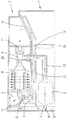
図4は、本発明の第1の実施形態を示す。これによれば、第1の真空掃除機3のみがベースステーション1に接続されている。概略断面図には、ベースステーション1がベース集塵室2を有し、第1のエア入口7と第1のエア出口8は、ベースステーション2と流体的に接続されるとともに、第1の真空掃除機3用の接続ポートとして使用可能である。ベース集塵室2にはフィルタバッグが配置されることが好適であり、掃除機集塵室5に到達した塵をフィルタバッグに収集することができる。第1のエア入口7及び第1のエア出口8に加えて、ベースステーション1はさらに第2のエア入口12及び第2のエア出口13を有する。これらは、第2の真空掃除機4の接続ポートとして機能する。第1のエア入口7と第2のエア入口12の間の流路、並びに、第1のエア出口8と第2のエア出口13の間の流路には、それぞれバルブ14、15が配置されている。それらのバルブは、第2の真空掃除機4がベースステーション1に接続され清浄化されるときに、第1の状態から第2の状態に切換可能である。
FIG. 4 shows a first embodiment of the present invention. According to this, only the
第1の真空掃除機3は、その吸引口17、排出口18、及びさらに別の清浄化口21によりベースステーション1の流路に接続される。さらに、第1の真空掃除機3は、掃除機集塵室5を有し、その中にエアフィルタ16、ここでは永久フィルタが設けられている。掃除機集塵室5は、エアダクト9により第1の真空掃除機3のファン11と接続されている。ファン11は、第1の真空掃除機3の通常の掃除動作中、エアを吸引口17からエアフィルタ16を通してファン11へと移送する。それにより、吸引されたエアに含まれる塵がエアフィルタ16に到達し、掃除機集塵室5に収集される。それにより、塵を除去されたエアのみがファン11に流れ、排出口18から排気される。
The
ベース集塵室2はさらに、接続ライン22を介してエアダクト9と接続される。ファン11によってベース集塵室2内に負圧を生じさせることができる。接続ライン22はまた、排出口18と第1のエア出口8を接続する接続ライン23と交差する(バルブ15が図4に示した位置にあるとき)。しかしながらこの場合、接続ライン22と接続ライン23の間は流体的には接続されていない。
The base
例示した第1の真空掃除機3の清浄化モードにおいては、第1の真空掃除機3の排出口18がベースステーション1の第1のエア出口8と流体的に接続され、第1の真空掃除機の吸引口17がベースステーション1の第1のエア入口7と流体的に接続される。ベースステーション1の第2のエア入口12及び第2のエア出口13は、バルブ14、15により閉鎖されることにより、周囲の空気が第2のエア入口12又は第2のエア出口13を通ってベースステーション1又は第1の真空掃除機3に侵入することはできない。
In the illustrated cleaning mode of the
第1の真空掃除機3の清浄化は、ユーザにより手動で開始されてもよく、又はそれに替えて、例えばベースステーション1に設けられたセンサ(図示せず)が第1の真空掃除機3のベースステーション1への接続を検知したとき自動的に開始されてもよい。その後、ファン11が始動され、第1の真空掃除機3のエアダクト9に設けられた吸引バルブ20が閉鎖されることによりエアダクト9が流体的に遮断され、そしてファン11はもはや掃除機集塵室5と直接的には流体的に接続されなくなる。ファン11により送出されるエアは、第1の真空掃除機3の排出口18を通って流れ、ベースステーション1に形成された流路を通って掃除機集塵室5に到達する。そこでエアは、エアフィルタ16に対して内側から供給されることにより、第1の真空掃除機3の吸引動作における通常の流れの方向とは逆方向に通過して流れる。エアフィルタ16の外側に堆積した塵と埃は、内側から外側に流れるエアに引きずられ、第1の真空掃除機3の吸引口17を通ってベースステーション1の第1のエア入口7に到達する。そこから、塵を伴うエアは最終的にベース集塵室2に到達し、ベース集塵室2に設けられたフィルタ、例えばフィルタバッグでフィルタリングされ、清浄化されたエアとしてベース集塵室2から第1の真空掃除機3のファン11へと流れる。このようにして、流路のループが閉じられる。
The cleaning of the
図5は、本発明の第2の実施形態を示しており、第1の真空掃除機3及び第2の真空掃除機4の双方がベースステーション1に接続されている。第1の真空掃除機3は、図4に基づいて説明した通り、ベースステーション1に接続されている。さらにこの場合、ベースステーション1の第2のエア入口12及び第2のエア出口13が、ここでは掃除ロボットである第2の真空掃除機4のエア接続部と接続されている。
FIG. 5 shows a second embodiment of the present invention, in which both the
第2の真空掃除機4もまた、エアフィルタ16を具備する掃除機集塵室6とファン11とを有している。掃除機集塵室6及びファン11は、エアダクト10と互いに接続されている。
The
ベースステーション1は、第2の真空掃除機4が第2のエア入口12及び第2のエア出口13に存在することを検知するセンサ(図示せず)、例えばタッチセンサを有してもよい。バルブコントローラ(図示せず)が、バルブ14、15を制御することにより、第2の真空掃除機4のエアダクト10がベース集塵室2及び第1の真空掃除機3のファン11に流体的に接続されてもよい。バルブ14は、第2のエア入口12とベース集塵室2の間の流体的接続を形成するように切り換えられる。バルブ15は、第2のエア出口13と第1の真空掃除機3のファン11の間の流体的接続を形成するように適切に切り換えられる。吸引バルブ20もまた、第1の真空掃除機3のエアダクト9の内部で自動的に閉鎖されることが好適である。
The
第2の真空掃除機4の掃除機集塵室6を清浄化し又は空にするために、第1の真空掃除機3のファン11が始動される。適切に切り換えられたバルブ14、15及び吸引バルブ20により、第1の真空掃除機3のファン11、第1の真空掃除機3の排出口18、ベースステーション1の第2のエア出口13、第2の真空掃除機4のエアダクト10、ベースステーション1の第2のエア入口12、ベース集塵室2、及び最後に再び第1の真空掃除機3のファン11の間に閉じた流路が形成される。これにより、第1の真空掃除機3のファン11と第2の真空掃除機4の掃除機集塵室6が協働することにより、第2の真空掃除機4の掃除機集塵室6に収容された塵が第1の真空掃除機3のファン11を用いてベースステーション1のベース集塵室2に移送される。そこに収集された塵は最終的に廃棄することができる。ベースステーション1自体は、個別のファンを有する必要はない。なぜなら、第1の真空掃除機3のファン11のみが、第1の真空掃除機3の掃除機集塵室5の清浄化及び第2の真空掃除機4の掃除機集塵室6の清浄化の双方のためにそれぞれ用いられるからである。
In order to clean or empty the vacuum cleaner
上述した実施形態の他に、変形形態ももちろん可能であり、例えば、別の形態のバルブ14、15、20、別の種類のバルブ14、15、20が設けられてもよく、又は、エア入口7、12及びエア出口8、13がベースステーション1内における別の位置に設けられてもよい。さらに、ベースステーション1が、手動又は電磁気的なバルブ制御を付加される等されてもよい。また、図示の実施形態に限定するものではない。
In addition to the above-described embodiments, variations are of course possible, for example, other forms of
1 ベースステーション
2 ベース集塵室
3 第1の真空掃除機
4 第2の真空掃除機
5、6 掃除機集塵室
7 第1のエア入口
8 第1のエア出口
9、10 エアダクト
11 ファン
12 第2のエア入口
13 第2のエア出口
14、15 バルブ
16 エアフィルタ
1
7
11
Claims (10)
前記ベースステーション(1)が、前記ベース集塵室(2)と流体的に接続される第2のエア入口(12)と、前記ベース集塵室(2)と流体的に接続される第2のエア出口(13)とを有し、該第2のエア入口(12)及び該第2のエア出口(13)が、第2の真空掃除機(4)のエアダクト(10)と流体的に接続可能であることにより、該第2の真空掃除機(4)の掃除機集塵室(6)に収容された塵が、前記第1の真空掃除機(3)のファン(11)を用いて該ベース集塵室(2)に移送可能であることを特徴とする
ベースステーション。 In order to clean and / or empty the vacuum cleaner dust collection chamber (5) of the first vacuum cleaner (3), the base dust collection chamber (2) and the base dust collection chamber (2) A first air inlet (7) connected to the base dust collection chamber (2) and a first air outlet (8) fluidly connected to the base dust collection chamber (2), the first air inlet (7) and The first air outlet (8) is fluidly connectable to the air duct (9) of the first vacuum cleaner (3), thereby the vacuum cleaner of the first vacuum cleaner (3). In the base station (1) in which the dust contained in the dust collection chamber (5) can be moved to the base dust collection chamber (2) using the fan (11) of the first vacuum cleaner (3),
The base station (1) has a second air inlet (12) fluidly connected to the base dust collection chamber (2), and a second fluidly connected to the base dust collection chamber (2). The second air inlet (12) and the second air outlet (13) are fluidly connected to the air duct (10) of the second vacuum cleaner (4). By being connectable, the dust housed in the vacuum cleaner dust collection chamber (6) of the second vacuum cleaner (4) uses the fan (11) of the first vacuum cleaner (3). The base station can be transferred to the base dust collection chamber (2).
Applications Claiming Priority (2)
| Application Number | Priority Date | Filing Date | Title |
|---|---|---|---|
| DE102014119192.7 | 2014-12-19 | ||
| DE102014119192.7A DE102014119192A1 (en) | 2014-12-19 | 2014-12-19 | Base station for a vacuum cleaner |
Publications (2)
| Publication Number | Publication Date |
|---|---|
| JP2016116852A JP2016116852A (en) | 2016-06-30 |
| JP6607604B2 true JP6607604B2 (en) | 2019-11-20 |
Family
ID=54754550
Family Applications (1)
| Application Number | Title | Priority Date | Filing Date |
|---|---|---|---|
| JP2015234486A Expired - Fee Related JP6607604B2 (en) | 2014-12-19 | 2015-12-01 | Base station for vacuum cleaner |
Country Status (6)
| Country | Link |
|---|---|
| EP (1) | EP3033983B1 (en) |
| JP (1) | JP6607604B2 (en) |
| CN (1) | CN105708385B (en) |
| DE (1) | DE102014119192A1 (en) |
| ES (1) | ES2629874T3 (en) |
| TW (1) | TWI683644B (en) |
Families Citing this family (21)
| Publication number | Priority date | Publication date | Assignee | Title |
|---|---|---|---|---|
| DE102015103825A1 (en) * | 2015-03-16 | 2016-09-22 | Vorwerk & Co. Interholding Gmbh | Emptying a dust chamber of a vacuum cleaner |
| DE102017103527A1 (en) * | 2017-02-21 | 2018-08-23 | Vorwerk & Co. Interholding Gmbh | Method for operating a vacuum cleaner having a permanent filter |
| DE102017113285A1 (en) * | 2017-06-16 | 2018-12-20 | Vorwerk & Co. Interholding Gmbh | System with at least two cleaning devices |
| US11672388B2 (en) * | 2017-09-22 | 2023-06-13 | Sharkninja Operating Llc | Hand-held surface cleaning device |
| EP4233666A3 (en) * | 2019-04-18 | 2023-09-20 | Vorwerk & Co. Interholding GmbH | Method for operating a cleaning system, base station and filter device |
| CN110664321A (en) * | 2019-08-21 | 2020-01-10 | 深圳市无限动力发展有限公司 | Recycle bin and cleaning system |
| CN110466918B (en) * | 2019-08-21 | 2022-08-05 | 深圳市无限动力发展有限公司 | Garbage recycling station and cleaning system |
| CN110623605B (en) * | 2019-08-21 | 2021-11-30 | 深圳市无限动力发展有限公司 | Workstation and cleaning system |
| DE102019213085B4 (en) | 2019-08-30 | 2023-06-29 | BSH Hausgeräte GmbH | Cleaning system with docking device |
| CN113057516B (en) * | 2020-01-02 | 2022-02-08 | 宁波方太厨具有限公司 | Multiphase fluid mixing cleaner |
| WO2021177572A1 (en) * | 2020-03-03 | 2021-09-10 | 엘지전자 주식회사 | Docking station and dust removal system including same |
| KR20210019940A (en) * | 2020-06-22 | 2021-02-23 | 엘지전자 주식회사 | Station for cleaner and controlling method thereof |
| KR20210130655A (en) * | 2020-04-22 | 2021-11-01 | 엘지전자 주식회사 | Station for Cleaner |
| KR20210130461A (en) * | 2020-04-22 | 2021-11-01 | 엘지전자 주식회사 | Stand for Cleaner |
| CN113827132B (en) * | 2020-06-23 | 2023-08-01 | 添可智能科技有限公司 | Recovery device and recovery method |
| KR102406189B1 (en) * | 2020-10-07 | 2022-06-10 | 엘지전자 주식회사 | Cleaner system |
| KR20220081702A (en) * | 2020-12-09 | 2022-06-16 | 엘지전자 주식회사 | Cleaner system |
| EP4265168A1 (en) * | 2020-12-16 | 2023-10-25 | LG Electronics Inc. | Cleaner system |
| US20220287528A1 (en) * | 2021-03-11 | 2022-09-15 | Techtronic Cordless Gp | Vacuum cleaner docking station |
| CN115211754B (en) * | 2022-01-27 | 2023-06-09 | 苏州简单有为科技有限公司 | Cleaning system |
| CN114766979B (en) * | 2022-05-11 | 2023-09-26 | 深圳市普森斯科技有限公司 | Cleaning method, cleaning base station and cleaning set of dust collector |
Family Cites Families (15)
| Publication number | Priority date | Publication date | Assignee | Title |
|---|---|---|---|---|
| DE10113789B4 (en) | 2001-03-21 | 2006-09-14 | BSH Bosch und Siemens Hausgeräte GmbH | Arrangement for the disposal of dirt with a mobile vacuum cleaner |
| JP3986310B2 (en) * | 2001-12-19 | 2007-10-03 | シャープ株式会社 | Parent-child type vacuum cleaner |
| EP2023788B1 (en) * | 2006-05-19 | 2011-09-07 | iRobot Corporation | Removing debris from cleaning robots |
| KR101204440B1 (en) * | 2007-02-26 | 2012-11-26 | 삼성전자주식회사 | Robot cleaner system having robot cleaner and docking station |
| DE102008011723B4 (en) * | 2008-02-28 | 2015-08-20 | Vorwerk & Co. Interholding Gmbh | Vacuum cleaners, in particular household vacuum cleaners, and methods for operating a vacuum cleaner |
| CN101992190B (en) * | 2009-08-28 | 2016-04-06 | 科沃斯机器人有限公司 | Ground Processing System and dirt cleaning thereof and emptying method |
| DE102010000607B4 (en) * | 2010-03-02 | 2022-06-15 | Vorwerk & Co. Interholding Gmbh | Household vacuum cleaner that can be used as a base station for an automatically movable suction and/or sweeping device |
| CN201755198U (en) * | 2010-04-14 | 2011-03-09 | 泰怡凯电器(苏州)有限公司 | Robot system |
| KR101483541B1 (en) * | 2010-07-15 | 2015-01-19 | 삼성전자주식회사 | Autonomous cleaning device, maintenance station and cleaning system having them |
| KR101496913B1 (en) * | 2010-11-03 | 2015-03-02 | 삼성전자 주식회사 | Robot cleaner, automatic exhaust station and robot cleaner system having the same |
| KR101467341B1 (en) * | 2011-04-04 | 2014-12-03 | 연세대학교 산학협력단 | Robot cleaner system having a sub-robot for corner cleaning |
| DE102011054162A1 (en) * | 2011-10-04 | 2013-04-04 | Vorwerk & Co. Interholding Gmbh | Assembled system of base station and automatic movable cleaning device e.g. household robotic vacuum cleaner, has base station with receptacle that is designed, so that self-positioning of dirt container in receptacle is achieved |
| CN202840553U (en) * | 2012-07-19 | 2013-03-27 | 烟台炅旼电器有限公司 | Multifunctional charging stand for wireless sweeper/manual cleaner |
| CN103565348B (en) * | 2012-07-27 | 2016-05-04 | 科沃斯机器人有限公司 | Intelligent cleaning system |
| DE102012109938A1 (en) * | 2012-10-18 | 2014-04-24 | Vorwerk & Co. Interholding Gmbh | Automatic movable floor dust collection apparatus used for household application, has sensor system that monitors movement of rotor shaft and fan wheel during dust exhaustion operation in the dust collection container |
-
2014
- 2014-12-19 DE DE102014119192.7A patent/DE102014119192A1/en not_active Withdrawn
-
2015
- 2015-12-01 ES ES15197182.7T patent/ES2629874T3/en active Active
- 2015-12-01 EP EP15197182.7A patent/EP3033983B1/en active Active
- 2015-12-01 JP JP2015234486A patent/JP6607604B2/en not_active Expired - Fee Related
- 2015-12-14 TW TW104141945A patent/TWI683644B/en not_active IP Right Cessation
- 2015-12-17 CN CN201510951488.0A patent/CN105708385B/en active Active
Also Published As
| Publication number | Publication date |
|---|---|
| DE102014119192A1 (en) | 2016-06-23 |
| TWI683644B (en) | 2020-02-01 |
| CN105708385A (en) | 2016-06-29 |
| CN105708385B (en) | 2019-06-18 |
| TW201632129A (en) | 2016-09-16 |
| JP2016116852A (en) | 2016-06-30 |
| EP3033983A1 (en) | 2016-06-22 |
| ES2629874T3 (en) | 2017-08-16 |
| EP3033983B1 (en) | 2017-06-21 |
Similar Documents
| Publication | Publication Date | Title |
|---|---|---|
| JP6607604B2 (en) | Base station for vacuum cleaner | |
| JP6726453B2 (en) | Base station for vacuum cleaners | |
| CN113226142B (en) | Robot cleaner, station and cleaning system | |
| CN107405033B (en) | Dust collector and base station system, dust collector, base station and method for emptying dust collecting chamber | |
| CN101164486B (en) | Electric vacuum cleaner | |
| CN105747993B (en) | Dust catcher | |
| CN107811578A (en) | Emptying station | |
| US10076218B2 (en) | Method for operating a vacuum cleaner having a cyclone separator and a vacuum cleaner having a cyclone separator | |
| CN106983448B (en) | Suction cleaning device and method for operating a suction cleaning device | |
| CN106963286B (en) | Air filter that can be backwashed and vacuum cleaner comprising such an air filter | |
| DK3047772T3 (en) | Vacuum Cleaner Robot | |
| CN106175595B (en) | Air filter capable of back flushing | |
| US20120151710A1 (en) | Reverse flow vacuum system | |
| CN115811953A (en) | Vacuum cleaner | |
| CN210124714U (en) | Cleaning device and cleaning device assembly | |
| JP4901552B2 (en) | Vacuum cleaner | |
| WO2016165612A1 (en) | Vacuum cleaner | |
| CN215400821U (en) | Dust collection garbage can | |
| WO2024047887A1 (en) | Vacuuming system | |
| CN115211754B (en) | Cleaning system | |
| WO2022201586A1 (en) | Vacuuming system | |
| KR101851586B1 (en) | Dust collector for vacuum cleaner | |
| TW202410846A (en) | Cleaning system | |
| WO2024049900A1 (en) | Vacuum cleaner and debris collector assembly | |
| CN116076944A (en) | Cleaning system for realizing multiple cleaning paths by utilizing single vacuum source |
Legal Events
| Date | Code | Title | Description |
|---|---|---|---|
| A621 | Written request for application examination |
Free format text: JAPANESE INTERMEDIATE CODE: A621 Effective date: 20180903 |
|
| A977 | Report on retrieval |
Free format text: JAPANESE INTERMEDIATE CODE: A971007 Effective date: 20190920 |
|
| TRDD | Decision of grant or rejection written | ||
| A01 | Written decision to grant a patent or to grant a registration (utility model) |
Free format text: JAPANESE INTERMEDIATE CODE: A01 Effective date: 20190926 |
|
| A61 | First payment of annual fees (during grant procedure) |
Free format text: JAPANESE INTERMEDIATE CODE: A61 Effective date: 20191017 |
|
| R150 | Certificate of patent or registration of utility model |
Ref document number: 6607604 Country of ref document: JP Free format text: JAPANESE INTERMEDIATE CODE: R150 |
|
| LAPS | Cancellation because of no payment of annual fees |