JP6526245B2 - Peripheral ventilation system for electronic display - Google Patents
Peripheral ventilation system for electronic display Download PDFInfo
- Publication number
- JP6526245B2 JP6526245B2 JP2017560902A JP2017560902A JP6526245B2 JP 6526245 B2 JP6526245 B2 JP 6526245B2 JP 2017560902 A JP2017560902 A JP 2017560902A JP 2017560902 A JP2017560902 A JP 2017560902A JP 6526245 B2 JP6526245 B2 JP 6526245B2
- Authority
- JP
- Japan
- Prior art keywords
- electronic display
- channel
- gap
- open loop
- loop fluid
- Prior art date
- Legal status (The legal status is an assumption and is not a legal conclusion. Google has not performed a legal analysis and makes no representation as to the accuracy of the status listed.)
- Active
Links
Images


Classifications
-
- H—ELECTRICITY
- H05—ELECTRIC TECHNIQUES NOT OTHERWISE PROVIDED FOR
- H05K—PRINTED CIRCUITS; CASINGS OR CONSTRUCTIONAL DETAILS OF ELECTRIC APPARATUS; MANUFACTURE OF ASSEMBLAGES OF ELECTRICAL COMPONENTS
- H05K7/00—Constructional details common to different types of electric apparatus
- H05K7/20—Modifications to facilitate cooling, ventilating, or heating
- H05K7/20954—Modifications to facilitate cooling, ventilating, or heating for display panels
- H05K7/20972—Forced ventilation, e.g. on heat dissipaters coupled to components
-
- H—ELECTRICITY
- H05—ELECTRIC TECHNIQUES NOT OTHERWISE PROVIDED FOR
- H05K—PRINTED CIRCUITS; CASINGS OR CONSTRUCTIONAL DETAILS OF ELECTRIC APPARATUS; MANUFACTURE OF ASSEMBLAGES OF ELECTRICAL COMPONENTS
- H05K7/00—Constructional details common to different types of electric apparatus
- H05K7/20—Modifications to facilitate cooling, ventilating, or heating
- H05K7/20009—Modifications to facilitate cooling, ventilating, or heating using a gaseous coolant in electronic enclosures
- H05K7/20136—Forced ventilation, e.g. by fans
- H05K7/20145—Means for directing air flow, e.g. ducts, deflectors, plenum or guides
-
- H—ELECTRICITY
- H05—ELECTRIC TECHNIQUES NOT OTHERWISE PROVIDED FOR
- H05K—PRINTED CIRCUITS; CASINGS OR CONSTRUCTIONAL DETAILS OF ELECTRIC APPARATUS; MANUFACTURE OF ASSEMBLAGES OF ELECTRICAL COMPONENTS
- H05K7/00—Constructional details common to different types of electric apparatus
- H05K7/20—Modifications to facilitate cooling, ventilating, or heating
- H05K7/20009—Modifications to facilitate cooling, ventilating, or heating using a gaseous coolant in electronic enclosures
- H05K7/20136—Forced ventilation, e.g. by fans
- H05K7/20154—Heat dissipaters coupled to components
Landscapes
- Engineering & Computer Science (AREA)
- Microelectronics & Electronic Packaging (AREA)
- Physics & Mathematics (AREA)
- Thermal Sciences (AREA)
- Devices For Indicating Variable Information By Combining Individual Elements (AREA)
- Cooling Or The Like Of Electrical Apparatus (AREA)
- Heat-Exchange Devices With Radiators And Conduit Assemblies (AREA)
Description
(関連出願の相互参照)
[0001]本出願は、2015年2月17日付けで提出された米国出願第14/624,268号の優先権を主張し、その参照によってその全体が本明細書に組み込まれたものである。
( Cross-reference to related applications )
[0001] This application claims priority to US application Ser. No. 14 / 624,268, filed Feb. 17, 2015, which is incorporated herein by reference in its entirety.
(技術分野)
[0002]本発明の実施形態は、一般に、電子ディスプレイ用のマウント及び冷却のシステムに関連する。
( Technical field )
Embodiments of the invention generally relate to mounting and cooling systems for electronic displays.
(背景)
[0003]電子ディスプレイは、しばしば、アウトドア環境又は他の領域に使用される時に、環境温度が高くなり得るため、又は太陽等の他の熱源の負荷がかかり得るため、ディスプレイ内部の温度が上昇することがある。しかしながら、単に周辺空気を取り入れるだけでは、敏感な部分に塵が入ることで汚染されて、故障を早めたりするので、ディスプレイは、特定の部分によっては、冷却することが困難になる。
( Background )
[0003] When the electronic display is often used in an outdoor environment or other areas, the temperature inside the display may rise because the environmental temperature may be high or it may be loaded with other heat sources such as the sun Sometimes. However, simply taking in ambient air may contaminate sensitive parts with dust, which may lead to premature failure, making the display difficult to cool in certain parts.
(発明的なコンセプトの概要)
[0004]例示的な実施形態は、ディスプレイ・アセンブリと、自立のディスプレイ・ハウジングと、を備えることができる。そのディスプレイ・アセンブリは、自立のディスプレイ・ハウジング内に設けられてもよい。ディスプレイ・アセンブリは、前部パネルの周辺に沿って配置される取入ギャップと、前部パネルの周辺の反対部分に沿って配置される排出ギャップと、を備えることができる。ファンは、開ループ流体が取入ギャップから入って電子ディスプレイの背後のチャネルを通り排出ギャップから出て行くように、配置することができる。
( Summary of the inventive concept )
[0004] Exemplary embodiments can comprise a display assembly and a free standing display housing. The display assembly may be provided in a free standing display housing. The display assembly can include an inlet gap disposed along the periphery of the front panel and an outlet gap disposed along an opposing portion of the periphery of the front panel. The fan can be arranged such that the open loop fluid enters the inlet gap and passes through the channel behind the electronic display and out the outlet gap.
[0005]同じファン又は追加ファンは、開ループ流体が任意選択である熱交換器も強制的に通過するように、配置することができる。また、追加の循環ファンを使用して、開ループ流体を熱交換器に循環させることができる。 [0005] The same fan or additional fans can be arranged to also force heat exchangers with open-loop fluid being optional. Also, an additional circulating fan can be used to circulate the open loop fluid to the heat exchanger.
[0006]バッファ・ゾーンは、取入ギャップと排出ギャップとの間に位置し、また、1つ又は複数の隔壁を有することが好ましく、その隔壁は、ハウジング内に吸気された後に開ループ流体の垂直方向の流れを実質的に制限又は禁止することができる。隔壁は、一般に、水平的に位置し、且つディスプレイ・アセンブリの垂直方向の中央付近に位置する(必須ではないが)。 [0006] The buffer zone is located between the intake gap and the discharge gap, and preferably has one or more partitions, which after being sucked into the housing, of the open loop fluid Vertical flow can be substantially restricted or inhibited. The bulkheads are generally located horizontally (although not necessarily) near the vertical center of the display assembly.
(図面の簡単な説明)
[0007]上述の特徴に加えて、本発明の他の態様は、以下の図面の説明及び例示的な実施形態から容易に理解できるものであり、図中の同様な参照符号は、同一又は等価の特徴を示している。
[0007] In addition to the features described above, other aspects of the present invention will be readily understood from the following description of the drawings and exemplary embodiments, and like reference numerals in the figures are identical or equivalent Show the features of
(例示的な実施形態の詳細な説明)
[0040]本発明は、以下に、その例示的な実施例が示されている添付図面を参照しながら、より詳細に説明する。なお、本発明は、多くの異なる形式で実施可能であるため、本明細書における例示的な実施例に限定されるべきではない。むしろ、これらの実施例の提供により、本開示は全くの完全なものとなり、当業者は、本発明の範囲を完全に理解することができる。但し、図面においては、層及び領域の大きさ、相対的な大きさは、明確化のために誇張されている場合がある。
( Detailed Description of an Exemplary Embodiment )
[0040] The invention will be described in more detail below with reference to the accompanying drawings, of which exemplary embodiments are shown. However, the present invention should not be limited to the exemplary embodiments herein, as it may be embodied in many different forms. Rather, the provision of these examples makes the present disclosure quite complete, and one of ordinary skill in the art can fully understand the scope of the present invention. However, in the drawings, the size and relative sizes of layers and regions may be exaggerated for clarity.
[0041]本明細書での用語は、特定の実施例のみを説明するために使用され、本発明を限定する意図はない。また、明細書において使用されている、単数形は、明らかにその文脈から異なることが明示されていない限り、複数形をも含む意図を持っている。また、用語「備える」及び/又は「備えている」は、本明細書における使用において、記載された特徴、整数、ステップ、動作、構成及び/又は要素の存在を明示していることを理解することができるが、1又は複数の他の特徴、整数、ステップ、動作、構成、構成要素、及び/又はそれらの群の存在を排除するものではない。 [0041] The terms used herein are used to describe specific embodiments only and are not intended to limit the present invention. Also, as used in the specification, the singular form is also intended to include the plural form unless the context clearly indicates otherwise. Also, it is understood that the terms "comprises" and / or "comprising" specify the presence of the recited features, integers, steps, acts, configurations and / or elements as used herein. It is possible, however, not to exclude the presence of one or more other features, integers, steps, operations, configurations, components and / or groups thereof.
[0042]本発明の実施例は、本発明の理想的な実施例(及び中間構造)が図示された概要である図面を参酌しながら、以下に説明する。従って、結果として図示された形状における変更、例えば、製造上の技法及び/又は許容誤差などは、予期されている。従って、本発明の実施例は、本出願で図示された領域の特定の形状に限定されることを意図しておらず、例えば製造からの結果物の形状には偏差を含むものである。 [0042] Embodiments of the present invention will be described below with reference to the drawings, which is a schematic overview of an ideal embodiment (and intermediate structure) of the present invention. Thus, changes in the shapes illustrated as a result, such as manufacturing techniques and / or tolerances, etc., are expected. Thus, embodiments of the present invention are not intended to be limited to the particular shape of the region illustrated in the present application, eg, including deviations in the shape of the result from manufacturing.
[0043]他に定義しない限り、本明細書で使用される用語(技術用語及び科学用語を含む)は、本発明が属する技術分野の当業者によって通常理解される意味を持つ。例えば一般的に用いられる辞書で定義された用語は、関連技術の文脈における意味と一致する意味を持つように理解されるべきであり、特に本明細書で定義されない限り理想的な意味又は過度に正式な意味で解釈されるものではない。 [0043] Unless otherwise defined, terms (including technical and scientific terms) used herein have meanings as commonly understood by one of ordinary skill in the art to which this invention belongs. For example, terms defined in a commonly used dictionary should be understood to have a meaning consistent with the meaning in the context of the relevant art, and in particular ideal or excessive unless otherwise defined herein. It is not to be interpreted in a formal sense.
[0044]図1は、電子ディスプレイ・アセンブリ5(以下、「アセンブリ」とも言う)の実施例を示す。電子ディスプレイ・アセンブリ5は、アセンブリ5の前部表面の大部分を覆うことが可能である前部パネル10を備える。前部パネル10は、透過であってもよく、また、電子ディスプレイ70の前に位置してもよい。ここで、電子ディスプレイ70は、好ましくは、前部パネル10の後ろに固定されている。例示的な実施例において、前部パネル10は、タッチ・スクリーンである。周囲壁55は、前部パネル10を取り囲むことができる。
[0044] FIG. 1 shows an example of an electronic display assembly 5 (hereinafter also referred to as "assembly"). The
[0045]自立のディスプレイ・ハウジング15は、アセンブリ5を取り囲むことができ、また、アセンブリ5を地面に貼り付け可能に構成することができる。例示的な実施例において、自立のディスプレイ・ハウジング15は、旗形に形成可能である。他の実施例において、自立のディスプレイ・ハウジング15は、バス停用のシェルタに一体化されるように、大きさを有し、且つ構成されてもよい。
[0045] A free standing
[0046]自立のディスプレイ・ハウジング15は、柱20、上部ビーム25及び基部30を備えることができる。例示的な実施例において、基部30は、固定具(例えばボルト)が通過できてグランドに固定できるような、選択的な開口35(例えば円形孔)を有することができる。開口35の数及び位置は、図示において、単なる実例に過ぎない。柱20の底部は、自立のディスプレイが地面に固定されるように、埋めることができる。幾つかの実施例において、柱20の底部をコンクリートに埋めることによって実施してもよい。自立のディスプレイ・ハウジング15及び関連する要素は、金属製(例えば、ステンレス鋼又はアルミニウム)であってもよい。
[0046] The free
[0047]上部ビーム25は、上部ビーム25の一方の側の大部分を覆う第2のディスプレイ40を更に備えることができる。例示的な実施例において、上部ビーム25は、液晶ディスプレイ(LCD)である。他の実施例において、第2のディスプレイ40は、静的なディスプレイであってもよく、それは、照明デバイス(例えばバックライト)と、静的ディスプレイ(例えばポスター)を収容するキャビティと、を有することができる。
The
[0048]1組の拡張部材50は、柱20の頂部から伸張することができる。拡張部材50は、自立のディスプレイ・ハウジング15、従ってアセンブリ5を適所でより一層固定するように、構成することができる。拡張部材50の数及び形状は、任意である。例示的な実施例において、これらの拡張部材50は、バス停用のシェルタに一体化されるように、大きさを有し、且つ構成されてもよい。
[0048] A set of
[0049]後続の図面を用いてより詳細に説明されるように、アセンブリ5は、周囲壁55と前部パネル10との間にギャップ45を更に備えることができ、これにより、流体(例えば周辺空気)は、アセンブリ5内及び外に、流れることができる。例示的な実施例において、アセンブリ5は、アセンブリ5の上半分で流体を取り込めるように、また、アセンブリ5の下半分で流体を排出できるように、構成することができる(図中の矢印参照)。これは、単なる実例に過ぎず、他の実施例では、アセンブリ5の上半分で流体を排出する一方、アセンブリ5の下半分で流体を吸引してもよい。
[0049] The
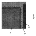
[0050]図2及び図3は、ギャップ45を示し、更に、アセンブリ5の周辺に沿って伸びるクロスのハッチングを表し、詳細を表すために、拡大されている。ギャップ45は、バッファ・ゾーン46を更に有することができる。バッファ・ゾーン46は、領域であってもよく、好ましくは、外部空気の流れを禁止するために、ギャップ45の取入部と排出部との間に設けられる。他の実施例において、バッファ・ゾーン46は、外部空気の流れを実施的に制限してもよい。例示的な実施例において、ギャップ45は、前部パネル10の周辺の周りに位置するが、バッファ・ゾーン46には存在しない。例示的な実施例において、バッファ・ゾーン46は、ディスプレイ・アセンブリ5の垂直方向のセンターラインの近くに配置され、典型的には、第1のバッファ・ゾーンがアセンブリの右手側に存在し、第2のバッファ・ゾーンがアセンブリの左手側に存在する。
[0050] Figures 2 and 3 show the
[0051]図4において、アセンブリ5は、アセンブリ5の背部表面の大部分を覆う背部パネル60を更に備えることができる。背部周囲壁54は、背部パネル60の側部を取り込むことができる。例示的な実施例において、背部周囲壁54は、周囲壁55と実質的に同じである。上部ビーム25は、第2のディスプレイ40と同様に、バックライト及びグラフィックを含む第3のディスプレイ41を更に備えることができる。例えばバックライトである照明ユニットは、背部パネル60の後ろに配置することができる。キャビティは、背部パネル60背面の背後に配置することができ、また、キャビティは、背部パネル60内に又は背部パネル60の後ろに位置する静的なディスプレイ(例えばポスター)を収容するように、構成することができる。代替的な実施例において、電子ディスプレイ・アセンブリ(例えばLCD)が、背部パネル60の後ろに配置されてもよい。
[0051] In FIG. 4, the
[0052]図1と同様に、後続の図面においてより詳細に説明することができ、アセンブリ5は、背部周囲壁54と背部パネル60との間に背部ギャップ44を更に備えることができ、これにより、流体(例えば周辺空気)は、アセンブリ5内及び外に、流れることができる。例示的な実施例において、図中の矢印で示すように、アセンブリ5は、アセンブリ5の上半分で流体を取り込めるように、また、アセンブリ5の下半分で流体を排出できるように、構成することができる(逆も可能である)。
[0052] Similar to FIG. 1, which can be described in more detail in the subsequent figures, the
[0053]本発明の例示的な実施例において、開ループ流体400の取込及び排出は、例えば上部及び下部の端のような、背部ギャップ44の選択部分に沿って実施されなくてもよい。他の実施例において、開ループ流体400の取込及び排出は、バッファ・ゾーン46の可能な限りの例外を除いて、背部ギャップ44の全部に沿って実施されてもよい。
[0053] In an exemplary embodiment of the present invention, intake and discharge of
[0054]図5では、前部パネル10は取り除かれており、また、前部パネル10の後ろであって周囲壁55の内側に固定可能である電子ディスプレイ70が示されている。アセンブリ5は、ディスプレイ70と第2のディスプレイとの間に、電子ディスプレイ70の上に設けられた1連の開口65を更に備えることができる。図示された開口65は、単なる実例に過ぎず、吸気開口65の数及び形状は、任意である。取込開口65は、流体(例えば、周辺空気)がディスプレイ70の背後を流れる開ループに入り易いように、構成することができる。1組の側部内部チャネル21及び22は、電子ディスプレイ70の各側部の長さの大部分に及ぶことができる。
[0054] In FIG. 5, the
[0055]図6では、背部パネル60は取り除かれており、また、背部パネル60の後ろに固定された内部背部パネル80が示されている。内部背部パネル80は、アセンブリ5の背面の大部分を覆うことができる。アセンブリは、内部背部パネル80の上であり、場合によって背部周囲壁54内に入っている、1連の背部吸気開口75を有することができる。図示された背部吸気開口75は、単なる実例に過ぎず、開口75の数及び形状は、任意である。後続の図面においてより詳細に説明するが、開口75は、開ループ流体の取込を容易に実施するように、構成することができる。
[0055] In FIG. 6, the
[0056]同様に、アセンブリ5は、内部背部パネル80の下であり、場合によって背部周囲壁54内に入っている、1連の背部排気開口85を有することができる。図示された背部排気開口85は、単なる実例に過ぎず、背部排気開口85の数及び形状は、任意である。後続の図面においてより詳細に説明するが、背部排気開口85は、開ループ流体の排出を容易に実施するように、構成することができる。任意選択であるファン81は、内部背部パネル80の背後であって背部排気開口85の上に固定することができる。ファン81は、開ループ流体の流れを制御するように、構成されている。ファン81の数は、任意である。他の実施例において、ファン81は、開ループの流路に沿って任意の場所に配置することができ、即ち、ファン81の位置は、吸気75と排気開口85との間で任意とすることができる。
[0056] Similarly, the
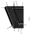
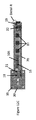
[0057]図7及び図8は、アセンブリ5の下半分を示し、また、自立のディスプレイ・ハウジング15を示す。側部ビーム90は、柱20の反対側に配置され、アセンブリ5の長さの大部分に及ぶことができる。側部ビーム90は、金属製であり、アセンブリ5の構造的支持及び剛性を提供することができる。電子機器キャビティ16は、アセンブリ5の内部に配置することができる。任意選択である熱交換器100は、電子機器キャビティ16の内部又は近くに固定することができる。例示的な実施形態において、熱交換器100は、交流熱交換器であるが、他の型の熱交換器、特に、逆流熱交換器等が使用されてもよい。1連の電子要素105は、電子機器キャビティ16でも固定することができる。後続の図面においてより詳細に説明するが、開ループ流体400(例えば、外部空気)は、熱交換器100に循環されてもよい。閉ループ流体(例えば、循環ガス700)は、電子機器キャビティに、また、電子要素105及び熱交換器100に、循環されてもよい。
[0057] Figures 7 and 8 show the lower half of the
[0058]後続の図面においてより詳細に説明するが、本実施例において、開ループ流体400は、ギャップ45及び任意選択である背部ギャップ44を介して、アセンブリ5から抜ける。流れを表す線で図示されるように、開ループ流体は、右側チャネル19から、ジグザグ経路を流れて、アセンブリ5から出て行く。代替的に、他の経路形状が使用されてもよく、それは明らかに意図されている。
[0058] As will be described in more detail in the subsequent figures, in this example, the
[0059]電子ディスプレイ70等の液晶ディスプレイを使用する場合、バックライト106は、電子ディスプレイ70の背後に配置することができ、また、好ましくは、直射型LEDバックライトであるが、他の照明源が実施例で用いられてもよい。プレート104又は他の実質的に平坦な部材は、バックライト106の背後に配置することができ、これにより、開ループ流体400を受け入れるチャネル102を生成することができる。好ましくは、チャネル102は、シールされて、開ループ流体400がディスプレイ・アセンブリの他の部分に、特に、電子要素16に、進入することを防止することができる。
[0059] When using a liquid crystal display, such as
[0060]図9及び図10は、アセンブリ5の上半分及び自立のディスプレイ・ハウジング15を示し、任意選択である1組の補強部材110を除き、それぞれ、下半分を示す図7及び図8と同様である。任意選択である補強部材110は、後続の図面でより詳細に説明する。後続の図面においてより詳細に説明するが、この実施例において、開ループ流体400は、ギャップ45及び任意選択である背部ギャップ44を介して、アセンブリ5に入ることができる。流れを表す線で図示されるように、開ループ流体400は、ジグザグ経路を流れて、右側チャネル19に向かう。代替的に、他の経路形状が使用されてもよく、それは明らかに意図されている。
[0060] Figures 9 and 10 show the upper half of the
[0061]図11は、図1の1実施例の正面平面図であり、また、断面線F−F、G−G及びH−Hを表す。 [0061] FIG. 11 is a front plan view of one embodiment of FIG. 1 and also represents cross-sectional lines F-F, G-G and H-H.
[0062]図12A及び図12Bは、1組のチャネル隔壁130と中央隔壁140とを示し、後続の図面でより詳細に説明されるように、実質的に水平的に位置し、且つアセンブリ5の垂直方向のセンターライン付近に位置することが好ましく、実施例では、垂直方向のセンターラインから離れて、それらはアセンブリ5の頂部又は底部の近くに位置することができる。
12A and 12B show a set of
[0063]この実施例において、図12Aは、開ループ流体400の吸気として指定されたギャップ45(及び任意選択である背部ギャップ44)の領域を示す。
[0063] In this example, FIG. 12A shows the area of gap 45 (and optional back gap 44) designated as intake of
[0064]これらの図及び図12Cで示されるように、ファン81の配置によって、開ループ流体400は、周辺空気(フィルタ後、又はフィルタされていない)の取込として一般的に使用されるギャップ45(及び任意選択である背部ギャップ44)の部分に入り込み、左側内部チャネル21(取込チャネル)の下方へ、チャネル102を横切り/又は通過し、右側内部チャネル22の下方へ、流体400の排気として使用されるギャップ45(及び任意選択である背部ギャップ44)の部分から出る。なお、左側及び右側の内部チャネル21及び22は、任意選択であり、代替的な実施例では、開ループ流体400用の以下の経路を含み、その経路は、周辺空気(フィルタ後、又はフィルタされていない)の取込として一般的に使用されるギャップ45(及び任意選択である背部ギャップ44)の部分に入り込み、チャネル102を横切り/又は通過し、流体400の排気として使用されるギャップ45(及び任意選択である背部ギャップ44)の部分から出る。
[0064] With the placement of
[0065]図12Cは、図11の切断線H−Hによる頂部平面断面図であり、また、細部(Detail)Rを表す。この実施例において、この図は、開ループ流体400の出口として指定されたギャップ45(及び任意選択である背部ギャップ44)の領域を示す。
[0065] FIG. 12C is a top plan cross-sectional view along the section line H-H of FIG. 11 and also represents Detail R. In this example, this figure shows the area of the gap 45 (and optionally the back gap 44) designated as the outlet of the
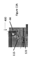
[0066]図13Aは、背部ギャップ44を介した開ループ流体400の取込を示す。開ループ流体400は、開口122を介した任意選択であるドア補強部材115を通り抜けることができる。
[0066] FIG. 13A shows uptake of
[0067]図13Bは、バッファ・ゾーン46の領域のアセンブリの例示的な実施例を示す。この実施例において、バッファ・ゾーン46は、ギャップ45(及び任意選択である背部ギャップ44)での、又は近くの、又は内側の範囲を備えることができ、それは、開ループ流体400の経路に沿って配置される1又は複数の流体をブロックする栓を含んで、実質的に何も通過させない。例示的な実施例において、バッファ・ゾーン46は、中央隔壁140と一緒にチャネル隔壁130を含むことができるが、幾つかの実施例では、チャネル隔壁130だけを利用することができる(流体400のドア隔壁の通り抜けを禁止する場合)。他の実施例では、左側及び右側の側部チャネル18及び19内にチャネル隔壁130を設けるよりも、バッファ・ゾーン46は、ギャップ44の近くに又は端に設けられた栓を含むことができる。一般的には、バッファ・ゾーンは、水平であり、且つアセンブリ5の垂直方向のセンターライン線の近くに設けられるが、アセンブリ5の頂部又は底部の近くに配置されてもよい。
[0067] FIG. 13B illustrates an exemplary embodiment of the assembly of the area of
[0068]なお、バッファ・ゾーン46は、アセンブリ5の横の両側に存在すべきであり、(仮に、背部ギャップ44が使用される場合)アセンブリ5の前部及び背部にも存在すべきであり、バッファ・ゾーン46は、アセンブリ5の横の両側に存在するアセンブリ5の前部ギャップ45(及び背部ギャップ44)の部分をブロックすることができる。
[0068] It should be noted that
[0069]図13Cは、背部ギャップ44を介した開ループ流体400の排出を示す。開ループ流体400は、開口122を介してドア補強部材115を通過することができる。
[0069] FIG. 13C shows the discharge of
[0070]図13A〜図13Cは背部ギャップ44を図示しているが、例示的な1実施例において、前部ギャップ45は、背部ギャップ44と同様の方向を有していることに留意すべきである。実質的に同じであるので、省略されている。
Although FIGS. 13A-13C illustrate the
[0071]図14は、ギャップ45及び背部ギャップ44の結合された領域を示す、また、クロスのハッチング領域を表す。実施例において、バッファ・ゾーン46の外側で、クロスのハッチング領域は、開ループ流体400の流れをギャップ45(及び任意選択である背部ギャップ44)の内又は外の何れか一方に許可することができる。
[0071] FIG. 14 shows the combined area of the
[0072]図15は、自立のディスプレイ・ハウジング15が取り外されたアセンブリ5を示す。ドア補強部材120は、前部パネル10のすぐ後ろに取り付けすることができる。幾つかの実施例において、ドア補強部材120は、前部パネル10の背面に取り付けることができる。ドア補強部材120は、実質的に、前部パネル10の周辺を及ぶことができる。ドア補強部材120は、金属製であるか、又は、アセンブリ5の構造的剛性及び強度を提供可能である適切な剛性を有する他の材料で構成することができる。ドア補強部材120は、1連の開口125を備えて、開ループ流体400の流れを可能にする。図示されるドア補強開口125は、単なる実例に過ぎない。開口125の数及び形状は、任意であることが意図されている。
[0072] FIG. 15 shows the
[0073]図16は、背部パネル60を分離して示す。例示的な実施例では、背部補強部材115は、背部パネル60の周辺端の周りに取り付けることができ、これにより、背部パネル60のフレームを形成することができる。ドア・キャビティ17は、背部パネル60、背部ドア補強部材115の内部表面、及び内部背部パネル80(現図に図示せず)の間の空間によって規定することができる。背部ギャップ44を介して取り込まれた開ループ流体400は、開口122を介して背部ドア補強部材115を通ってドア・キャビティ17に進むので、開ループ流体400bと考えることができる。図示された開口122は、単なる実例に過ぎず、開口の数及び形状は、任意であることが意図されている。任意選択である補強部材110は、細長い部材の形で、背部パネル60の長さを実質的に伸張することができる。任意選択である補強部材110は、金属製であるか、ポリマー製であるか、又は、背部パネル60の構造的剛性及び強度を提供可能である適切な剛性を有する他の材料で構成することができる。任意選択である補強部材110は、1連の開口135を備えて、開ループ流体400bが任意選択である補強部材110を流れることを容易することができる。図示の、任意選択である補強部材110及び開口135は、単なる実例に過ぎず、任意選択である補強部材110及び開口135の数及び形状は、任意であることが意図されている。
[0073] FIG. 16 shows the
[0074]ドア・キャビティ17内を移動する開ループ流体400の一部は、開ループ流体400bとして呼ばれる。図示されるように、開ループ流体400bは、内部パネル80の後ろを通過し、吸気開口75を経由して取り込まれてチャネル102に向かうことができる。例示的な1実施例において、開ループ流体400bは、吸気開口75を流れて左側チャネル18に向かい、チャネル102を横切って、左側チャネル19から出て行く。
[0074] The portion of the
[0075]図17は、流れを表す線で、アセンブリ5の前部及び背部を通る開ループ流体400aの循環を示す。開ループ流体は、ギャップ45を経由して取り込み、開口125を介してドア・補強部材120を進行し、また、右側内部チャネル22及び側部ビーム90の一部によって規定される場合もある右側チャネル19を垂直に進行することができる。同様に、開ループ流体400aは、背部ギャップ44を経由して取り込み、開口122を介してドア・補強部材115を進行し、開口135を介して任意選択である補強部材110を進行し、また、右側チャネル19に入る。アセンブリ5の反対側で、同様の経路を形成することができ、これにより、開ループ流体は、左側内部チャネル21及び柱20の一部によって規定される場合もある左側チャネル19に進入することができる。
[0075] FIG. 17 shows the circulation of
[0076]実質的に同一の逆の流体経路を形成して、アセンブリ5の反対側の端の上において開ループ流体を排気することができる。再び、実施例において、吸気は、上半分又はアセンブリ5で実施され、排気は、アセンブリ5の下半分で実施される。他の実施例において、吸気は下半分で実施し、排気はアセンブリ5の上半分で実施してもよい。或いは、他の実施例において、吸気は右側で実施し、排気は左側で実施し、バッファ・ゾーン46は、アセンブリの頂部及び底部の端に配置されて、2つの流路の吸気のクロスを防止してもよい。
[0076] The open loop fluid may be evacuated above the opposite end of the
[0077]図18は、ギャップ45及び背部ギャップ44からの取込み後の開ループ流体400の例示的な流路を示す。背部ギャップ44を介して吸気される開ループ流体400は、任意選択であるドア補強部材間のドア・キャビティ17に沿って進み、開ループ流体400bと呼ぶことができる。開ループ流体400bは、その後、背部内部パネル80に沿って垂直に進み、背部吸気開口75を経由して取り込まれる。開ループ流体400の他の部分は、左側の側部チャネル18及び右側の側部チャネル19に沿って進み、開ループ流体400aと呼ぶことができる。側部チャネル18及び19を垂直に進んだ後に、開ループ流体400aは、これらの側部チャネルの頂部の上を進み、吸気開口75を介して取り込まれる。同様に、開ループ流体は、ギャップ45を介して取り込まれ、前部パネル10の下でドア補強開口125を進み、吸気開口65を介して取り込まれる。
[0077] FIG. 18 illustrates an exemplary flow path of
[0078]図19Aは、自立のディスプレイ・ハウジング15が取り外された図1のアセンブリの背面斜視図であり、また、細部(Detail)Sを表す。
[0078] FIG. 19A is a rear perspective view of the assembly of FIG. 1 with the
[0079]図19Bは、自立のディスプレイ・ハウジング15が取り外された図1のアセンブリの前面斜視図であり、また、細部(Detail)Tを表す。
[0079] FIG. 19B is a front perspective view of the assembly of FIG. 1 with the
[0080]図20は、開ループ流体400aと呼ばれる、右側の側部チャネル19を進む開ループ流体400の部分を示す。開ループ流体400aは、右側内部チャネル22の頂部の上で、右側の側部チャネル19内を移動し、吸気開口75に入って行くことができる。
[0080] FIG. 20 shows the portion of
[0081]図20と同様であるが前面からの視点で、図21は、開ループ流体400aと呼ばれる、左側の側部チャネル18を進む開ループ流体400の部分を示す。開ループ流体400aは、左側内部チャネル21の頂部の上で、左側の側部チャネル18内を移動し、吸気開口65に入って行くことができる。
[0081] Similar to FIG. 20, but from a front view, FIG. 21 shows a portion of
[0082]図22は、図4の断面線B−Bの底部斜視断面図である。開ループ流体400a/400bは、様々な吸気開口75及び65を介して取り入れられると、統合されて、その後に、熱交換器100の開ループ気体経路を流れる開ループ流体400の第1の部分と、チャネル102に向けられる開ループ流体400の第2の部分とに、分けられる。
[0082] FIG. 22 is a bottom perspective cross-sectional view of cross-sectional line B-B of FIG. The
[0083]1又は複数の循環ファン32を使用して、循環ガス700を電子機器を横切らせて、且つ熱交換器100の開ループ気体経路を通過させるとともに、電子ディスプレイ70と前部パネル10との間で閉ループを形成する。この実施例において、循環ガス700は、ガスケット200の通路内の開口部を通過する一方、開ループ流体400は、ガスケットの通路の周りを進行し、実質的に開ループ流体400と循環ガス700との混合を防止することができる。しかしながら、この設計は、反転してもよく、この場合、循環ガス700がガスケット200の通過経路の周りを通過する一方、外部空気400がガスケット200の通過経路を進んでもよい。
[0083] One or more circulating
[0084]図示されている開ループ流体400の流れは、左側内部チャネル21の横を通り、ガスケット200を通るクロスによって通過し、電子ディスプレイ70の背後(ここでは、バックライト106の背後)を走るチャネル102に入ることができる。チャネル102は、好ましくは、電子ディスプレイ70の背面(ここでは、バックライト106の背後)とプレート104との間によって定義することができる。好ましくは波形で好ましくは連続的であるヒートシンクが理想的にはチャネル内に配置されて、開ループ流体400との対流によって取り除かれる電子ディスプレイ101から連続的なヒートシンクへの熱伝導は、促進される。
[0084] The illustrated flow of open loop fluid 400 passes by the cross through the
[0085]熱交換器100は、好ましくは、循環ガス700又は開ループ流体400の何れか一方を含むチャネルを定義する複数の層を含む。好ましくは、循環ガス700は、開ループ流体400との混合が不可能である。
[0086]開ループ流体400の流れは、チャネル102を進行し、ガスケット200の経路の周りを再び通過し、左側内部チャネル22に入ることができ、最終的には、開ループ流体400の排出として指定されるギャップ45(及び任意選択である背部ギャップ44)の部分から出て行く。この実施例において、図示された循環ガス700は、熱交換器100を出て、ガスケット200の経路内の開口部、及びその後の電子ディスプレイ70と前部パネル10との間を通過する。
[0086] The flow of
[0087]好ましい実施例において、熱交換器100は、交流熱交換器である。しかしながら、多くの型の熱交換器が既知であるので、それらは、本明細書におけるどの実施例に使用してもよい。熱交換器100は、交流熱交換器、又は、平行熱交換器、又は逆流熱交換器であってもよい。実施例において、熱交換器100は、薄いプレート群からなる、複数の積層を有する。プレートは、波形、ハニカム、又は管状の設計であってもよく、複数のチャネル/経路/管は、プレートの長さ方向に下降する。隣接する各プレートで経路の方向が交替するように、プレートは、積み上げられて、これにより、プレートの各経路は、隣接するプレートの経路と実質的に垂直である。従って、外部空気又は循環ガスは、ガスの進路と平行に走るチャネル又は経路を有するプレートを通過するだけで、例示的な熱交換器に入ることができる。なぜならば、プレートが交互に配置されているので、循環ガス及び開ループ流体は、互いに隣接するプレート内を進むことができ、ガス自身が混合されることなく、2つのガス間での熱交換が実施される(熱交換器が適切にシールされていることが好ましい)。
[0087] In a preferred embodiment,
[0088]熱交換器の代替的な設計において、開チャネルは、1組の波形、ハニカム、又は管状のプレート間に配置することができる。開チャネルは、隣接するプレートの経路に垂直な方向に進むことができる。この開チャネルは、隣接するプレートの経路に垂直な方向にプレートの対向する2つの端間に2つの材料又はテープ(特に、強接着(VHB)テープ)を走らせることによって、生成することができる。従って、第1の方向に熱交換器に入ったガスは、(スリップ又はテープに平行に)開チャネルを通ることができる。(第1の方向と実質的に垂直である)第2の方向に熱交換器に入ったガスは、隣接するプレートの経路を通ることができる。 [0088] In an alternative design of the heat exchanger, the open channels can be disposed between a set of corrugated, honeycomb or tubular plates. The open channel can travel in a direction perpendicular to the path of the adjacent plate. This open channel can be created by running two materials or tapes (especially strong adhesive (VHB) tape) between the two opposite ends of the plate in a direction perpendicular to the path of the adjacent plate . Thus, the gas entering the heat exchanger in the first direction can pass through the open channel (parallel to the slip or tape). Gas entering the heat exchanger in a second direction (which is substantially perpendicular to the first direction) can pass through the path of the adjacent plates.
[0089]他の型の交流熱交換器は、第1のガスを含み、且つ第2のガスの経路に垂直に進む複数の管を備えることができる。第1のガスを含む管の上を第2のガスが流れる時に、2つのガス間で熱交換が実施される。多くの型の交流熱交換器が存在することは明らかであり、どの型も本明細書の実施例で機能するであろう。 [0089] Another type of alternating current heat exchanger can comprise a plurality of tubes that contain a first gas and run vertically to the path of the second gas. Heat exchange is performed between the two gases as the second gas flows over the tube containing the first gas. Clearly, there are many types of alternating current heat exchangers, and any type will work in the examples herein.
[0090]例示的な熱交換器は、比較的に低い熱抵抗を有する側壁となるプレートを有し、2つのガス間の熱交換は、容易に実施することができる。多くの材料を使用して熱交換を生成することができる。好ましくは、その材料は、非腐食性であり、耐腐食性であり、軽量であり、また安価である。典型的には、高熱伝導率であるため、熱交換器には金属が用いられ、実施例で実現されている。しかしながら、電子ディスプレイの熱的な条件を満たすプラスチック及び混合物も見つかっている。熱交換器のプレートを構成する材料として、例示的な実施例は、ポリプロピレンを利用することができる。ポリプロピレンは、熱伝導率が低いように思えるが、側壁の厚さが薄くて、表面積が大きいので、全体としては、熱抵抗が低いことが分かっている。従って、例示的な熱交換器は、プラスチック製であってもよく、薄くて軽量であるディスプレイ・アセンブリを製造することができる。特に、各プレート層に、波形のプラスチックを使用することで、交互に積み重ねることができる(即ち、各隣接プレートは、周囲のプレートに垂直な方向に進むチャネルを有する。)。 [0090] An exemplary heat exchanger has a plate that is a side wall with relatively low thermal resistance, and heat exchange between two gases can be easily performed. Many materials can be used to produce heat exchange. Preferably, the material is non-corrosive, corrosion resistant, lightweight and inexpensive. Typically, metals are used for heat exchangers and are realized in the examples because of their high thermal conductivity. However, plastics and mixtures which meet the thermal requirements of electronic displays have also been found. An exemplary embodiment may utilize polypropylene as the material comprising the plates of the heat exchanger. Polypropylene seems to have a low thermal conductivity, but it has been found that overall it has a low thermal resistance due to the thin sidewall thickness and large surface area. Thus, the exemplary heat exchanger can be made of plastic and can produce a thin and lightweight display assembly. In particular, for each plate layer, corrugated plastic can be used to stack alternately (i.e. each adjacent plate has channels running in a direction perpendicular to the surrounding plates).
[0091]例示的な実施例において、電子ディスプレイ70は、直射型LEDバックライトLCDであり、LEDバックライトは、熱的な伝導性を有する基板(好ましくは、金属コアPCB)上にマウントされた複数のLEDを含むことができる。LEDバックライトの裏面は、好ましくは、チャネル102と熱伝導可能な伝導性を有する熱伝導性プレートを含むことができる。
[0091] In the exemplary embodiment, the
[0092]循環ガス700及び開ループ流体400は、任意の数のガス状物質であってもよい。幾つかの実施例において、すべてのガスとして、空気が使用されてもよい。循環ガス700は、電子ディスプレイ70の前を移動するので、好ましくは、実質的に透明であり、これにより、観察者に画像の見え方に影響を与えないことができる。また、循環ガス700は、好ましくは、汚染物質及び/又は微粒子(例えば、埃、不純物、花粉、水蒸気、煙など)を実施的に含まないものであり、これにより、画質への悪影響及び/又は内部電子部品への損傷を防止することができる。一般的には、例示的な実施例では、開ループ流体400として、周辺空気を利用することができる。
[0092] Circulating
[0093]冷却システムは、連続的に運転することができる。しかしながら、必要に応じて、温度検出デバイスが電子ディスプレイ内に組み込まれて、温度が所定の閾値に到達する時に検出してもよい。このような場合、ディスプレイ内の温度が所定値に到達した時に、様々な冷却ファンが選択的に可動してもよい。所定の閾値は、選択的であってもよく、システムは、ディスプレイの温度を許容範囲内に有利に維持するように構成することができる。典型的には、サーモスタット・アセンブリを使用して、この作業を実行することができる。温度検出デバイスとして、熱電対が使用されてもよい。 [0093] The cooling system can be operated continuously. However, if desired, a temperature detection device may be incorporated into the electronic display to detect when the temperature reaches a predetermined threshold. In such a case, various cooling fans may be selectively moved when the temperature in the display reaches a predetermined value. The predetermined threshold may be optional, and the system can be configured to advantageously maintain the temperature of the display within an acceptable range. Typically, a thermostat assembly can be used to perform this task. A thermocouple may be used as a temperature detection device.
[0094]図23〜図25は、中央隔壁140を示し、中央隔壁140は、好ましくは、実質的に水平的に位置し、且つアセンブリ5の垂直方向のセンターライン付近に位置し、実施例では、背部パネル60の表面の中心線に実質的に沿って伸びる垂直方向の上記センターラインから離れて、中央隔壁140はアセンブリ5の頂部又は底部に配置することもできる。右側のチャネル隔壁130は、自立のディスプレイ・ハウジング15の右側内部端の中心線に実質的に沿って伸びて、中央隔壁140と整列させることができる。同様に、左側のチャネル隔壁130は、アセンブリ5の左側内部端に固定して、中央隔壁140と整列させることができる。
[0094] Figures 23-25 show
[0095]中央隔壁140、右側のチャネル隔壁130、及び左側のチャネル隔壁130(以後、集合的には、「水平パーティション」)は、ドア・キャビティ17を上半分及び下半分に実質的に分割するように、構成することができる。水平パーティションは、ドア・キャビティ17の上半分及び下半分の間に実質的な気密シールを形成するように、構成することができる。任意選択的に、水平パーティションは、上記の上半分及び下半分の間の気密シールを提供するために、水平パーティションと一緒に利用される伸張可能な材料(例えばポリウレタン発泡体)を更に備えることができる。例示的な実施例において、中央隔壁140は、十分に曲げ可能な材料(例えば、ポリマー)から構成されて、ドア・キャビティ17に気密シールを形成することができる。代替的な実施例において、中央隔壁140は、固くて曲がらない材料から構成されてもよい。例示的な実施例において、右側のチャネル隔壁130及び左側のチャネル隔壁130は、固くて曲がらなくてもよい。
[0095] The
[0096]例示的な実施例において、開ループ流体400は、アセンブリ5の上半分に、ギャップ45(及び任意選択である背部ギャップ44)を介して取り込まれる。上記の開ループ流体400aは、その流体部分が右側のチャネル隔壁130に到達し、且つそれ以降の移動を禁止されるまで、右側のチャネル19に沿って移動することができる。同様に、上記の開ループ流体400aは、その流体部分が左側のチャネル隔壁130に到達するまで、左側のチャネル18に沿って移動することができる。開ループ流体の上記の部分は、反対方向に垂直的に戻るように強制されて、先の図面で説明したように、結果として吸気開口65及び75を介して取り込まれるまで、それぞれ、右側のチャネル19及び左側のチャネル18の上半分で循環する。
[0096] In the exemplary embodiment,
[0097]同様の方法で、開ループ流体400bは、その流体400bの部分が中央隔壁140に到達し、且つそれ以降の移動を禁止されるまで、ドア・キャビティ17に沿って移動することができる。このように、取り込まれた(しかしながら、熱交換器100又はチャネル102を通っていない)開ループ流体400bは、ギャップ45(及び任意選択である背部ギャップ44)から排出されることになる熱交換器100又はチャネル102を通った流体400bと混合されない。
[0097] In a similar manner,
[0098]先の図面で説明したように、開ループ流体400は、結果として排気開口85で排出されるまで、任意選択である熱交換器100を循環することができる。その後、開ループ流体400は、右側の側部チャネル19又は左側の側部チャネル18に戻ることができ、そこで垂直的に移動する。右側チャネル隔壁130及び左側チャネル隔壁130は、それぞれ、開ループ流体400がアセンブリ5の中心線を超えて移動することを防止し、従って、アセンブリ5の各半分からの開ループ流体が混合することを防止することができる。つまり、吸気開口65及び75を経由してまだ取り込まれていない開ループ流体は、吸気開口65及び75を経由して既に取り込まれた開ループ流体と混合しない。右側の隔壁130及び左側の隔壁130に出くわした開ループ流体は、結果として、ギャップ45(及び任意選択である背部ギャップ44)を介してアセンブリ5から排気されるまで、それぞれ、反対方向に垂直的に戻ることを強制される。
[0098] As described in the previous figures, the
[0099]図26A及び図26Bは、チャネル隔壁130の例示的な実施例を示す。このような実施例において、チャネル隔壁141の一部は、(必要に応じて)開ループ流体400aの一部がチャネル隔壁130を通過できるように、調整可能であり、これにより、開ループ流体の吸気及び排気間の限定された量の混合が可能となる。このような実施例において、チャネル隔壁142の第2の部分は、静的であってもよく、それらは調整されないで、吸気及び排気の開ループ流体が混合しないような、実質的に気密なシールを形成することがでる。他の実施例において、チャネル隔壁130の全体は、調整可能であってもよい。更なる他の実施例において、チャネル隔壁130の全体は、静的であってもよい。
[0099] Figures 26A and 26B illustrate an exemplary embodiment of the
[0100]開示された実施例の精神及び範囲からすれば、多くの型のディスプレイの冷却のために提供可能であることを理解することができるであそう。実例であって限定されない実施例は、以下のどの電子画像アセンブリにも用いることができる:LCD(すべての型)、発光ダイオード(LED)、有機発光ダイオード(OLED)、電解放電ディスプレイ(FED)、発光ポリマー(LEP)、有機EL(OEL)、プラズマ・ディスプレイ、及び他の薄型パネル電子画像アセンブリ。加えて、実施例は、他の型のディスプレイに使用してもよく、まだ発見されていなくてもよい。特に、システムは、フルカラーで薄型パネルOLEDディスプレイによく適しているであろう。例示的な実施例はまた、大型(55インチ以上)LEDバックライトで高精細度液晶ディスプレイ(LED)に利用することができる。本明細書の実施例は、アウトドア環境によく適していると同時に、ディスプレイの熱的安定性が危険であり得る屋内用途(工場/産業環境、スパ施設、ロッカールーム)にも適合することができる。 [0100] Given the spirit and scope of the disclosed embodiments, it can be appreciated that it can be provided for cooling of many types of displays. An illustrative, non-limiting example can be used for any of the following electronic imaging assemblies: LCD (all types), light emitting diodes (LEDs), organic light emitting diodes (OLEDs), electrolytic discharge displays (FEDs), Light emitting polymers (LEP), organic EL (OEL), plasma displays, and other thin panel electronic imaging assemblies. In addition, embodiments may be used for other types of displays and may not yet be found. In particular, the system would be well suited for full color, thin panel OLED displays. The exemplary embodiment can also be utilized for high definition liquid crystal displays (LEDs) with large (55 inches or more) LED backlights. The embodiments herein are well suited to the outdoor environment, but can also be adapted to indoor applications (factory / industrial environment, spa facilities, locker rooms) where thermal stability of the display may be dangerous. .
[0101]当該技術分野で既知であるように、電子ディスプレイは、縦置き又は横置きでよく、どちらも本明細書の実施例に使用することができる。 [0101] As known in the art, electronic displays may be in portrait or landscape orientation, either of which may be used in the examples herein.
[0102]図面で示された様々な冷却ループは、水平的又は垂直的であるが、特定の実施例によっては、逆転してもよく、或いは、変更してもよいことは、明らかである。従って、開ループは、水平又は垂直に、また、時計周り又は反時計周りに走ることができる。加えて、開ループは、水平的又は垂直的であって、左から右に、右から左に、上から下に、或いは、下から上に、走ることもできる。 Although the various cooling loops shown in the figures are horizontal or vertical, it will be appreciated that, depending on the particular implementation, they may be reversed or changed. Thus, the open loop can run horizontally or vertically, and clockwise or counterclockwise. In addition, the open loop can be horizontal or vertical and run from left to right, right to left, top to bottom, or bottom to top.
[0103]本発明の好ましい実施例を示し、説明したが、当業者は、多くの変形及び変更を説明した発明に加えて、それが特許請求の範囲内であることを理解することができるであろう。更に、上述の構成要素の多くは、同様に機能し、請求項の発明の精神に含まれる他の構成要素に、変更又は置換することができる。それゆえに、本発明は、添付の特許請求の範囲によって示されるように、限定されることを意図されているものである。 While the preferred embodiment of the present invention has been shown and described, those skilled in the art will appreciate that it is within the scope of the claims, in addition to the invention which has described many variations and modifications. I will. In addition, many of the components described above can be modified or replaced with other components that function similarly and are included in the spirit of the claimed invention. Therefore, the present invention is intended to be limited as indicated by the appended claims.
Claims (10)
前記電子ディスプレイの前に配置される前部パネルと、
前記前部パネル及び前記電子ディスプレイを受け入れるハウジングと、
前記前部パネルの周辺の第1垂直及び第1水平の部分に沿って配置される、開ループ流体を取り込むための取込ギャップと、
前記前部パネルの前記周辺の第2垂直及び第2水平の部分に沿って配置される、開ループ流体を排出するための排出ギャップと、
前記電子ディスプレイの後ろに配置されるチャネルと、
開ループ流体が前記取込ギャップから前記チャネルに移動可能な第1の気体経路と、
前記開ループ流体が前記チャネルから前記排出ギャップに移動可能な第2の気体経路と、
前記開ループ流体の流れを形成するように配置されるファンと、
前記取込ギャップと前記排出ギャップとの間に配置されるバッファ・ゾーンと、
前記バッファ・ゾーン内に設けられる中央隔壁と、
垂直的に配置され、且つ前記第1の気体経路の少なくとも一部を形成する第1の側部チャネルと、
垂直的に配置され、且つ前記第2の気体経路の少なくとも一部を形成する第2の側部チャネルと、
前記第1の側部チャネル内に設けられるチャネル隔壁と、
を備える電子ディスプレイ・アセンブリ。 Electronic display ,
A front panel disposed in front of the electronic display;
A housing for receiving the front panel and the electronic display,
A capture gap for capturing an open loop fluid disposed along a first vertical and a first horizontal portion of the periphery of the front panel;
Are arranged in the second vertical and second horizontal portion of the periphery of the front panel, a discharge gap for discharging the open loop fluid,
A channel located behind the electronic display;
A first gas path through which an open loop fluid can move from the intake gap to the channel;
A second gas path through which the open loop fluid can move from the channel to the discharge gap;
A fan arranged to create a flow of the open loop fluid;
A buffer zone disposed between the intake gap and the discharge gap;
A central bulkhead provided in the buffer zone;
A first side channel vertically disposed and forming at least a portion of the first gas path;
A second side channel disposed vertically and forming at least a portion of the second gas path;
A channel bulkhead provided in the first side channel;
Electronic display assembly comprising:
前記電子ディスプレイ用のハウジングと、
前記電子ディスプレイの意図された観察者と対向するように、前記ハウジングの上に設けられる取込ギャップと、
前記電子ディスプレイの意図された前記観察者と対向するように、前記ハウジングの上に設けられる排出ギャップと、
前記電子ディスプレイの後ろに配置されるチャネルと、
垂直的に配置され、且つ前記取込ギャップと前記チャネルとの間の気体の通行を可能にする第1の側部チャネルと、
垂直的に配置され、且つ前記チャネルと前記排出ギャップとの間の気体の通行を可能にする第2の側部チャネルと、
開ループ流体を前記取込ギャップに流入させ、前記第1の側部チャネルを介して、前記チャネルを介して、前記第2の側部チャネルを介して、前記排出ギャップから排出させるように、配置されるファンと、
前記取込ギャップと前記排出ギャップとの間に配置されるバッファ・ゾーンと、
前記バッファ・ゾーンと同じ垂直方向の高さに設けられる中央隔壁と、
前記第1の側部チャネル内に設けられるチャネル隔壁と、
を備える電子ディスプレイ・アセンブリ。 Electronic display,
A housing for the electronic display;
A capture gap provided on the housing to face the intended viewer of the electronic display;
A discharge gap provided above the housing to face the intended observer of the electronic display;
A channel located behind the electronic display;
A first side channel disposed vertically and enabling passage of gas between the intake gap and the channel;
A second side channel disposed vertically and enabling passage of gas between the channel and the discharge gap;
Arrangement to flow open loop fluid into the intake gap and out the discharge gap through the first side channel, through the channel, through the second side channel, And the fans
A buffer zone disposed between the intake gap and the discharge gap;
A central bulkhead provided at the same vertical height as the buffer zone;
A channel bulkhead provided in the first side channel;
Electronic display assembly comprising:
前記循環ガスが前記熱交換器を強制的に通過するように、配置される循環ファンと、
を更に備える請求項4に記載の電子ディスプレイ・アセンブリ。 A heat exchanger having a first path for open loop fluid and a second path for circulating gas;
A circulating fan arranged to force the circulating gas to pass through the heat exchanger;
The electronic display assembly of claim 4 , further comprising:
前記排出ギャップは、前記アセンブリの反対の垂直方向の半分に設けられる、請求項4に記載の電子ディスプレイ・アセンブリ。 The capture gap is provided in a first vertical half of the assembly,
5. The electronic display assembly of claim 4 , wherein the discharge gap is provided in the opposite vertical half of the assembly.
を更に備える請求項4に記載の電子ディスプレイ・アセンブリ。 5. The electronic display assembly according to claim 4 , further comprising: a door cavity behind the electronic display that receives open loop fluid from the first side channel and directs it to a channel behind the electronic display.
前記電子ディスプレイを取り囲むハウジング及び前部パネルと、
前記電子ディスプレイの垂直方向の中央の上に配置され、且つ前記前部パネルと前記ハウジングとの間に位置する取込ギャップと、
前記電子ディスプレイの垂直方向の中央の下に配置され、且つ前記前部パネルと前記ハウジングとの間に位置する排出ギャップと、
開ループ流体用の第1の経路と循環ガス用の第2の経路とを有する熱交換器と、
前記循環ガスが前記熱交換器を強制的に通過するように、配置される循環ファンと、
前記取込ギャップと前記排出ギャップとの間であって前記電子ディスプレイの垂直方向の中央の近くに配置される中央隔壁と、
開ループ流体の流れを前記取込ギャップに入れて、前記熱交換器を介して、前記排出ギャップから出させるように、配置されるファンと、
垂直的に配置され、且つ前記取込ギャップと前記熱交換器との間の気体の通行を可能にする第1の側部チャネルと、
垂直的に配置され、且つ前記熱交換器と前記排出ギャップとの間の気体の通行を可能にする第2の側部チャネルと、
前記第1の側部チャネル内に設けられる第1の側部のチャネル隔壁と、
前記第2の側部チャネル内に設けられる第2の側部のチャネル隔壁と、
を備える電子ディスプレイ・アセンブリ。 Electronic display,
A housing and a front panel surrounding the electronic display;
A capture gap located above the vertical center of the electronic display and located between the front panel and the housing;
A discharge gap located below the vertical center of the electronic display and located between the front panel and the housing;
A heat exchanger having a first path for open loop fluid and a second path for circulating gas;
A circulating fan arranged to force the circulating gas to pass through the heat exchanger;
A central bulkhead disposed between the intake gap and the discharge gap and near the vertical center of the electronic display;
A fan arranged to bring open loop fluid flow into the intake gap and out of the exhaust gap via the heat exchanger;
A first side channel disposed vertically and enabling passage of gas between the intake gap and the heat exchanger;
A second side channel vertically disposed and enabling passage of gas between the heat exchanger and the discharge gap;
A first side channel bulkhead provided in the first side channel;
A second side channel bulkhead provided in the second side channel;
Electronic display assembly comprising:
Applications Claiming Priority (3)
| Application Number | Priority Date | Filing Date | Title |
|---|---|---|---|
| US14/624,268 | 2015-02-17 | ||
| US14/624,268 US9723765B2 (en) | 2015-02-17 | 2015-02-17 | Perimeter ventilation system for electronic display |
| PCT/US2016/017973 WO2016133852A1 (en) | 2015-02-17 | 2016-02-15 | Perimeter ventilation system for electronic display |
Publications (3)
| Publication Number | Publication Date |
|---|---|
| JP2018511838A JP2018511838A (en) | 2018-04-26 |
| JP2018511838A5 JP2018511838A5 (en) | 2018-08-09 |
| JP6526245B2 true JP6526245B2 (en) | 2019-06-05 |
Family
ID=56622514
Family Applications (1)
| Application Number | Title | Priority Date | Filing Date |
|---|---|---|---|
| JP2017560902A Active JP6526245B2 (en) | 2015-02-17 | 2016-02-15 | Peripheral ventilation system for electronic display |
Country Status (8)
| Country | Link |
|---|---|
| US (3) | US9723765B2 (en) |
| EP (1) | EP3259968B1 (en) |
| JP (1) | JP6526245B2 (en) |
| KR (1) | KR102109072B1 (en) |
| CN (1) | CN107251671B (en) |
| AU (1) | AU2016220308B2 (en) |
| CA (1) | CA2976116C (en) |
| WO (1) | WO2016133852A1 (en) |
Cited By (17)
| Publication number | Priority date | Publication date | Assignee | Title |
|---|---|---|---|---|
| US10721836B2 (en) | 2008-03-03 | 2020-07-21 | Manufacturing Resources International, Inc. | Electronic display with cooling |
| US10925174B2 (en) | 2017-04-27 | 2021-02-16 | Manufacturing Resources International, Inc. | Field serviceable and replaceable assembly |
| US10973156B2 (en) | 2014-04-30 | 2021-04-06 | Manufacturing Resources International, Inc. | Dual electronic display assembly |
| US11019735B2 (en) | 2018-07-30 | 2021-05-25 | Manufacturing Resources International, Inc. | Housing assembly for an integrated display unit |
| US11096317B2 (en) | 2019-02-26 | 2021-08-17 | Manufacturing Resources International, Inc. | Display assembly with loopback cooling |
| US11191193B2 (en) | 2008-12-18 | 2021-11-30 | Manufacturing Resources International, Inc. | System for cooling an electronic image assembly with circulating gas and ambient gas |
| US11470749B2 (en) | 2020-10-23 | 2022-10-11 | Manufacturing Resources International, Inc. | Forced air cooling for display assemblies using centrifugal fans |
| US11477923B2 (en) | 2020-10-02 | 2022-10-18 | Manufacturing Resources International, Inc. | Field customizable airflow system for a communications box |
| US11507141B2 (en) | 2019-04-03 | 2022-11-22 | Manufacturing Resources International, Inc. | Electronic display assembly with a channel for ambient air in an access panel |
| US11744054B2 (en) | 2021-08-23 | 2023-08-29 | Manufacturing Resources International, Inc. | Fan unit for providing improved airflow within display assemblies |
| US11744036B2 (en) | 2016-03-04 | 2023-08-29 | Manufacturing Resources International, Inc. | Cooling system for double sided display assembly |
| US11762231B2 (en) | 2021-08-23 | 2023-09-19 | Manufacturing Resources International, Inc. | Display assemblies inducing turbulent flow |
| US11778757B2 (en) | 2020-10-23 | 2023-10-03 | Manufacturing Resources International, Inc. | Display assemblies incorporating electric vehicle charging equipment |
| US11919393B2 (en) | 2021-08-23 | 2024-03-05 | Manufacturing Resources International, Inc. | Display assemblies inducing relatively turbulent flow and integrating electric vehicle charging equipment |
| US11966263B2 (en) | 2021-07-28 | 2024-04-23 | Manufacturing Resources International, Inc. | Display assemblies for providing compressive forces at electronic display layers |
| US11968813B2 (en) | 2021-11-23 | 2024-04-23 | Manufacturing Resources International, Inc. | Display assembly with divided interior space |
| US12004311B2 (en) | 2023-12-15 | 2024-06-04 | Manufacturing Resources International, Inc. | Housing assembly for an integrated display unit |
Families Citing this family (42)
| Publication number | Priority date | Publication date | Assignee | Title |
|---|---|---|---|---|
| US8854595B2 (en) | 2008-03-03 | 2014-10-07 | Manufacturing Resources International, Inc. | Constricted convection cooling system for an electronic display |
| US8773633B2 (en) | 2008-03-03 | 2014-07-08 | Manufacturing Resources International, Inc. | Expanded heat sink for electronic displays |
| US8497972B2 (en) | 2009-11-13 | 2013-07-30 | Manufacturing Resources International, Inc. | Thermal plate with optional cooling loop in electronic display |
| US9173325B2 (en) | 2008-03-26 | 2015-10-27 | Manufacturing Resources International, Inc. | Heat exchanger for back to back electronic displays |
| US8693185B2 (en) | 2008-03-26 | 2014-04-08 | Manufacturing Resources International, Inc. | System and method for maintaining a consistent temperature gradient across an electronic display |
| US8749749B2 (en) | 2008-12-18 | 2014-06-10 | Manufacturing Resources International, Inc. | System for cooling an electronic image assembly with manifolds and ambient gas |
| ES2790406T3 (en) | 2012-10-16 | 2020-10-27 | Mri Inc | Rear tray cooling assembly for electronic display |
| US10524384B2 (en) | 2013-03-15 | 2019-12-31 | Manufacturing Resources International, Inc. | Cooling assembly for an electronic display |
| US9648790B2 (en) | 2013-03-15 | 2017-05-09 | Manufacturing Resources International, Inc. | Heat exchanger assembly for an electronic display |
| KR101894027B1 (en) | 2013-07-08 | 2018-08-31 | 매뉴팩처링 리소시스 인터내셔널 인코포레이티드 | Figure eight closed loop cooling system for electronic display |
| US9723765B2 (en) | 2015-02-17 | 2017-08-01 | Manufacturing Resources International, Inc. | Perimeter ventilation system for electronic display |
| US9857618B2 (en) * | 2015-05-18 | 2018-01-02 | Michael S. Barnes | Display enclosure with passive cooling system |
| EP3616481A4 (en) | 2017-04-27 | 2020-12-23 | Manufacturing Resources International, Inc. | System and method for preventing display bowing |
| GB2565997B (en) * | 2017-04-28 | 2019-10-16 | Amscreen Group Ltd | Crossflow heat-exchangers |
| US10455225B2 (en) * | 2017-05-12 | 2019-10-22 | Pure Depth Limited | Multi-layered display with interstitial layer air filter |
| KR102021554B1 (en) * | 2017-07-31 | 2019-11-04 | 엘지전자 주식회사 | A Cooler for Display Device |
| KR102020536B1 (en) * | 2017-07-31 | 2019-09-10 | 엘지전자 주식회사 | A Cooler for Display Device |
| US10559965B2 (en) | 2017-09-21 | 2020-02-11 | Manufacturing Resources International, Inc. | Display assembly having multiple charging ports |
| CN110267503B (en) * | 2019-07-16 | 2020-12-22 | 合肥统旭智慧科技有限公司 | Outdoor high bright liquid crystal display forced air cooling system |
| CN111798758B (en) * | 2019-07-16 | 2023-03-31 | 友达光电股份有限公司 | Display device |
| US11496091B2 (en) | 2019-08-27 | 2022-11-08 | Manufacturing Resources International, Inc. | Electronic display assemblies with solar panels |
| KR102186602B1 (en) * | 2019-09-04 | 2020-12-03 | 엘지전자 주식회사 | A Cooler for Display Device |
| USD913277S1 (en) | 2019-09-25 | 2021-03-16 | Manufacturing Resources International, Inc. | Electronic display kiosk |
| USD913276S1 (en) | 2019-09-25 | 2021-03-16 | Manufacturing Resources International, Inc. | Electronic display kiosk |
| USD913278S1 (en) | 2019-09-25 | 2021-03-16 | Manufacturing Resources International, Inc. | Electronic display kiosk |
| USD916975S1 (en) * | 2019-10-08 | 2021-04-20 | Manufacturing Resources International, Inc. | Combined electronic display assemblies and pole |
| USD916971S1 (en) * | 2019-10-08 | 2021-04-20 | Manufacturing Resources International, Inc. | Combined electronic display assembly and pole |
| USD916974S1 (en) * | 2019-10-08 | 2021-04-20 | Manufacturing Resources International, Inc. | Combined electronic display assemblies and pole |
| USD916972S1 (en) * | 2019-10-08 | 2021-04-20 | Manufacturing Resources International, Inc. | Combined electronic display assembly and pole |
| USD916190S1 (en) * | 2019-10-08 | 2021-04-13 | Manufacturing Resources International, Inc. | Combined electronic display assemblies and pole |
| USD916976S1 (en) * | 2019-10-08 | 2021-04-20 | Manufacturing Resources International, Inc. | Combined electronic display assemblies and pole |
| USD916977S1 (en) * | 2019-10-08 | 2021-04-20 | Manufacturing Resources International, Inc. | Combined electronic display assemblies and pole |
| USD916189S1 (en) * | 2019-10-08 | 2021-04-13 | Manufacturing Resources International, Inc. | Combined electronic display assembly and pole |
| USD916973S1 (en) * | 2019-10-08 | 2021-04-20 | Manufacturing Resources International, Inc. | Combined electronic display assembly and pole |
| USD934159S1 (en) | 2019-10-29 | 2021-10-26 | Manufacturing Resources International, Inc. | Canopy with solar powered electronic menu board |
| USD1010858S1 (en) | 2019-10-29 | 2024-01-09 | Manufacturing Resources International, Inc. | Bus shelter with solar powered electronic displays |
| USD958059S1 (en) | 2019-10-29 | 2022-07-19 | Manufacturing Resources International, Inc. | Solar powered electronic display assembly with pole mount |
| USD957317S1 (en) | 2019-10-29 | 2022-07-12 | Manufacturing Resources International, Inc. | Solar powered electronic display kiosk |
| USD993906S1 (en) | 2021-06-04 | 2023-08-01 | Manufacturing Resources International, Inc. | Combined solar powered electronic display assembly with charging station |
| USD964920S1 (en) | 2021-06-04 | 2022-09-27 | Manufacturing Resources International, Inc. | Solar powered electronic display assembly |
| CN114786392B (en) * | 2022-05-16 | 2024-01-26 | 深圳市润达通电子有限公司 | Prevent PCBA mainboard that breaks has heat dissipation circulation function |
| US11997808B2 (en) | 2022-08-31 | 2024-05-28 | Manufacturing Resources International, Inc. | Display assembly with unobstructed zone |
Family Cites Families (371)
| Publication number | Priority date | Publication date | Assignee | Title |
|---|---|---|---|---|
| US5432526A (en) | 1970-12-28 | 1995-07-11 | Hyatt; Gilbert P. | Liquid crystal display having conductive cooling |
| US4093355A (en) | 1977-02-04 | 1978-06-06 | General Motors Corporation | Symmetrical internal heater for liquid crystal display |
| FR2542893B1 (en) | 1983-03-18 | 1985-06-21 | Thomson Csf | COLOR VISUALIZATION SCREEN WITH SMECTIC LIQUID CRYSTAL |
| JPS6082745A (en) | 1983-10-12 | 1985-05-10 | Tokiwa Sangyo Kk | Boiler |
| US4634225A (en) | 1984-12-24 | 1987-01-06 | General Electric Co. | Transflective liquid crystal display with integral heating unit and temperature sensor |
| US4748765A (en) | 1986-07-18 | 1988-06-07 | Martin Dennis K | Livewell apparatus and method |
| US4763993A (en) | 1987-04-30 | 1988-08-16 | N-View Corporation | Liquid crystal display for projection systems |
| JPH063354B2 (en) | 1987-06-23 | 1994-01-12 | アクトロニクス株式会社 | Loop type thin tube heat pipe |
| US4952925A (en) | 1988-01-25 | 1990-08-28 | Bernd Haastert | Projectable passive liquid-crystal flat screen information centers |
| JPH0262015A (en) | 1988-08-29 | 1990-03-01 | Toshiba Corp | Transformer |
| US4952783A (en) | 1989-03-20 | 1990-08-28 | W. H. Brady Co. | Light transmitting flexible film electrical heater panels |
| JPH02307080A (en) | 1989-05-22 | 1990-12-20 | Nec Corp | Liquid-cooled bt device |
| US5029982A (en) | 1989-09-11 | 1991-07-09 | Tandy Corporation | LCD contrast adjustment system |
| JPH03153212A (en) | 1989-11-10 | 1991-07-01 | Hitachi Ltd | Liquid crystal display device |
| US5088806A (en) | 1990-01-16 | 1992-02-18 | Honeywell, Inc. | Apparatus and method for temperature compensation of liquid crystal matrix displays |
| US5247374A (en) | 1990-04-05 | 1993-09-21 | Stanley Electric Co., Ltd. | Liquid crystal display device with common heater between two cells |
| US5132666A (en) | 1990-09-17 | 1992-07-21 | Travel-Ad, Inc. | Vehicle-mounted electronic display system |
| US5282114A (en) | 1991-11-05 | 1994-01-25 | Codar Technology Inc. | Ruggedized computer assembly providing accessibility and adaptability to, and effective cooling of, electronic components |
| JP2585003Y2 (en) | 1992-06-18 | 1998-11-11 | 日本電気ホームエレクトロニクス株式会社 | Liquid crystal cooler for liquid crystal projector |
| JP2618791B2 (en) | 1992-09-07 | 1997-06-11 | 東北リコー株式会社 | Liquid crystal display cooling device |
| US5293930A (en) | 1992-09-24 | 1994-03-15 | Hewlett-Packard Company | Surface-to-air heat exchanger for electronic devices |
| US5351176A (en) | 1992-12-31 | 1994-09-27 | North Atlantic Industries, Inc. | Panel for a computer including a hinged door with integral display |
| US6902378B2 (en) | 1993-07-16 | 2005-06-07 | Helix Technology Corporation | Electronically controlled vacuum pump |
| JP2981586B2 (en) | 1993-10-15 | 1999-11-22 | ダイヤモンド電機株式会社 | heatsink |
| US7231967B2 (en) | 1994-01-31 | 2007-06-19 | Building Performance Equipment, Inc. | Ventilator system and method |
| JP3234740B2 (en) | 1994-06-09 | 2001-12-04 | キヤノン株式会社 | Image display device |
| US5983543A (en) | 1994-10-05 | 1999-11-16 | Hillstrom; David U. | Outdoor menu display device |
| JP3393937B2 (en) | 1994-10-18 | 2003-04-07 | 富士写真フイルム株式会社 | Lamp temperature control device and color thermal printer using the same |
| SE505272C2 (en) | 1994-12-14 | 1997-07-28 | Ericsson Telefon Ab L M | Cooling system for telecommunications equipment |
| US5767489A (en) | 1994-12-14 | 1998-06-16 | Hewlett-Packard Company | Enhanced resolution liquid crystal microthermography method and apparatus |
| JP3179989B2 (en) | 1995-01-13 | 2001-06-25 | 松下電工株式会社 | Display device |
| US6007205A (en) | 1995-03-30 | 1999-12-28 | Seiko Epson Corporation | Optical lens unit having internalized fan unit and projection apparatus housing the same |
| JP3275908B2 (en) | 1995-03-30 | 2002-04-22 | セイコーエプソン株式会社 | Projection display device |
| US5559614A (en) | 1995-05-01 | 1996-09-24 | Motorola, Inc. | Liquid crystal display with integral heater and method of fabricating same |
| JPH08305301A (en) | 1995-05-10 | 1996-11-22 | Sony Corp | Liquid crystal display device |
| JPH08339034A (en) | 1995-06-13 | 1996-12-24 | Matsushita Electric Ind Co Ltd | Liquid crystal display device for overhead projector |
| US5621614A (en) | 1995-08-24 | 1997-04-15 | Lucasey Manufacturing Company | Apparatus for mounting and enclosing an appliance |
| US5657641A (en) | 1995-09-13 | 1997-08-19 | Kooltronic, Inc. | Panel mounted cooling system |
| GB9522249D0 (en) | 1995-10-31 | 1996-01-03 | Smiths Industries Ltd | Display associates |
| JPH09223883A (en) | 1996-02-16 | 1997-08-26 | Hitachi Ltd | Cooling equipment of electronic apparatus |
| US6003015A (en) | 1996-02-28 | 1999-12-14 | Hm Electronics, Inc. | Order confirmation system and method of using same |
| JPH09246766A (en) | 1996-03-13 | 1997-09-19 | Fanuc Ltd | Enclosed electronic equipment case |
| JPH09307257A (en) | 1996-05-20 | 1997-11-28 | Fujitsu General Ltd | Image display device |
| JP3739486B2 (en) | 1996-06-13 | 2006-01-25 | 富士通株式会社 | Outdoor installation cabinet |
| JPH10123964A (en) | 1996-08-30 | 1998-05-15 | Sony Corp | Liquid crystal display device |
| US5748269A (en) | 1996-11-21 | 1998-05-05 | Westinghouse Air Brake Company | Environmentally-sealed, convectively-cooled active matrix liquid crystal display (LCD) |
| KR100242834B1 (en) | 1996-12-04 | 2000-02-01 | 윤종용 | An apparatus for emitting heat of lcd monitor |
| US6219113B1 (en) | 1996-12-17 | 2001-04-17 | Matsushita Electric Industrial Co., Ltd. | Method and apparatus for driving an active matrix display panel |
| US6089751A (en) | 1996-12-30 | 2000-07-18 | Honeywell Inc. | Transparent temperature sensor for an active matrix liquid crystal display |
| DE69840133D1 (en) | 1997-02-18 | 2008-11-27 | Canon Kk | Power supply unit with substrate-mounted transformer and power supply unit |
| JPH10268309A (en) | 1997-03-21 | 1998-10-09 | Furontetsuku:Kk | Liquid crystal display device |
| KR100233431B1 (en) | 1997-04-10 | 1999-12-01 | 윤종용 | Protection apparatus of chock circuit board in microwave oven |
| US6215655B1 (en) | 1997-10-31 | 2001-04-10 | Lacerta Enterprises, Inc. | Drive-in ordering apparatus |
| US5991153A (en) | 1997-10-31 | 1999-11-23 | Lacerta Enterprises, Inc. | Heat transfer system and method for electronic displays |
| US5864465A (en) | 1997-11-04 | 1999-01-26 | Liu; Michael | Device for cooling central processing units |
| US5808418A (en) | 1997-11-07 | 1998-09-15 | Honeywell Inc. | Control mechanism for regulating the temperature and output of a fluorescent lamp |
| JPH11160727A (en) | 1997-12-01 | 1999-06-18 | Advanced Display Inc | Liquid crystal display device |
| US6211934B1 (en) | 1997-12-24 | 2001-04-03 | Honeywell Inc. | Method of and apparatuses for reducing infrared loading on display devices |
| US6504713B1 (en) | 1998-01-22 | 2003-01-07 | Iv Phoenix Group, Inc. | Ultra-rugged, high-performance computer system |
| IL137200A (en) | 1998-02-19 | 2003-09-17 | L 3 Comm Corp | Method for cooling a lamp backlighting module of a liquid crystal display |
| TW445386B (en) | 1998-03-16 | 2001-07-11 | Hitachi Ltd | Thin-type display |
| JPH11296094A (en) | 1998-04-10 | 1999-10-29 | Matsushita Electric Ind Co Ltd | Heat radiating method of plasma display |
| KR20000000118U (en) | 1998-06-02 | 2000-01-15 | 윤종용 | Heat dissipation and heating device for communication equipment enclosure |
| TW393666B (en) | 1998-06-15 | 2000-06-11 | Acer Display Tech Inc | A plasma display device having a heated airflow guiding groove |
| JP2000010501A (en) * | 1998-06-18 | 2000-01-14 | Sony Corp | Mounting structure for panel type display device |
| US6428198B1 (en) | 1998-07-07 | 2002-08-06 | Alliedsignal Inc. | Display system having a light source separate from a display device |
| US6241903B1 (en) | 1998-08-20 | 2001-06-05 | Physical Optics Corporation | Diffuser master and method of manufacture |
| US6220713B1 (en) | 1998-10-23 | 2001-04-24 | Compaq Computer Corporation | Projection lens and system |
| JP4114194B2 (en) | 1998-10-29 | 2008-07-09 | 日本精機株式会社 | Head-up display device |
| US6437978B1 (en) | 1998-12-04 | 2002-08-20 | Sony Corporation | Cooling device, cooling method, and electronic apparatus |
| US6392727B1 (en) | 1998-12-31 | 2002-05-21 | Honeywell International Inc. | Reduced reflectance polarized display |
| CA2291931C (en) | 1999-01-06 | 2003-12-30 | Pfizer Pharmaceuticals Inc. | Isochroman compounds and their production process |
| US6933991B2 (en) | 1999-01-22 | 2005-08-23 | White Electronic Designs Corp. | Super bright low reflectance liquid crystal display |
| US6157432A (en) | 1999-01-29 | 2000-12-05 | Hewlett-Packard Company | Heated ferroelectric liquid crystal spatial light modulator with improved contrast, improved grayscale resolution, and decreased pixel sticking when operated in a non-DC balanced mode |
| US6191839B1 (en) | 1999-05-03 | 2001-02-20 | Rockwell Collin, Inc. | Patterned thermal sensor |
| JP3571965B2 (en) | 1999-07-21 | 2004-09-29 | シャープ株式会社 | Liquid crystal display |
| FI108962B (en) | 1999-08-20 | 2002-04-30 | Nokia Corp | Cabinet cooling system |
| US6701143B1 (en) | 1999-12-15 | 2004-03-02 | Vert, Inc. | Apparatus, methods, and computer programs for displaying information on mobile signs |
| US6812851B1 (en) | 1999-12-15 | 2004-11-02 | Vert, Inc. | Apparatuses for displaying information on vehicles |
| US6535266B1 (en) | 1999-12-16 | 2003-03-18 | Rockwell Collins, Inc. | Closed loop LCD heater system |
| US6411042B1 (en) | 1999-12-29 | 2002-06-25 | Honeywell International Inc. | Display cold spot temperature regulator |
| US6476883B1 (en) | 2000-05-05 | 2002-11-05 | Adaptive Micro Systems, Inc. | Enclosure system for electronic displays and method for making same |
| US6812982B2 (en) | 2000-05-12 | 2004-11-02 | Fuji Photo Film Co., Ltd. | Optical compensatory sheet producing method and apparatus, thermal treating method and apparatus, and dust removing method and apparatus |
| US20020065046A1 (en) | 2000-07-18 | 2002-05-30 | Vert, Inc. | Apparatuses, methods, and computer programs for showing information on a vehicle having multiple displays |
| US20020112026A1 (en) | 2000-07-18 | 2002-08-15 | Leonid Fridman | Apparatuses, methods, and computer programs for displaying information on signs |
| US6850209B2 (en) | 2000-12-29 | 2005-02-01 | Vert, Inc. | Apparatuses, methods, and computer programs for displaying information on vehicles |
| US20020164962A1 (en) | 2000-07-18 | 2002-11-07 | Mankins Matt W. D. | Apparatuses, methods, and computer programs for displaying information on mobile units, with reporting by, and control of, such units |
| US20020009978A1 (en) | 2000-07-18 | 2002-01-24 | Semyon Dukach | Units for displaying information on vehicles |
| JP2002158475A (en) | 2000-11-20 | 2002-05-31 | Fujitsu General Ltd | Hermetically sealed enclosure for planar display device |
| JP4402280B2 (en) | 2000-11-22 | 2010-01-20 | シャープ株式会社 | Liquid crystal display |
| US20040036622A1 (en) | 2000-12-15 | 2004-02-26 | Semyon Dukach | Apparatuses, methods, and computer programs for displaying information on signs |
| JP3594900B2 (en) | 2000-12-19 | 2004-12-02 | 株式会社日立製作所 | Display integrated computer |
| JP4460784B2 (en) | 2001-01-31 | 2010-05-12 | シャープ株式会社 | Liquid crystal display |
| ATE247323T1 (en) | 2001-02-12 | 2003-08-15 | Innowert Service Ct In Ges Fue | DEVICE FOR HOLDERING AND COOLING FLAT PANEL DISPLAYS |
| US6825828B2 (en) | 2001-02-23 | 2004-11-30 | General Digital Corporation | Backlit LCD monitor |
| JP4708587B2 (en) | 2001-03-07 | 2011-06-22 | Nec液晶テクノロジー株式会社 | Display device |
| US6607027B2 (en) | 2001-04-05 | 2003-08-19 | Modine Manufacturing Company | Spiral fin/tube heat exchanger |
| US20020149714A1 (en) | 2001-04-16 | 2002-10-17 | Robert Anderson | Ruggedized flat panel display assembly |
| US6493440B2 (en) | 2001-04-23 | 2002-12-10 | Gilbarco Inc. | Thermal management for a thin environmentally-sealed LCD display enclosure |
| KR100793727B1 (en) | 2001-05-18 | 2008-01-10 | 삼성전자주식회사 | Liquid crystal display device |
| NL1018243C2 (en) | 2001-06-08 | 2002-12-10 | Oce Tech Bv | Printhead for an image-forming device and image-forming device provided with such a printhead. |
| US6351381B1 (en) | 2001-06-20 | 2002-02-26 | Thermal Corp. | Heat management system |
| JP3471772B2 (en) | 2001-07-26 | 2003-12-02 | Necビューテクノロジー株式会社 | projector |
| US6727468B1 (en) | 2001-08-06 | 2004-04-27 | Rockwell Collins | Flexible heating system having high transmissivity |
| JP2003076286A (en) | 2001-09-06 | 2003-03-14 | Ngk Insulators Ltd | Cooling system for display device |
| JP2003140559A (en) | 2001-11-07 | 2003-05-16 | Nitto Denko Corp | Filmlike filter for preventing glass breakage and plasma display device |
| US6813152B2 (en) | 2002-01-18 | 2004-11-02 | Apw Ltd. | Method for improving airflow in subrack mechanics by using a hybrid serial/parallel fan configuration |
| US6976330B2 (en) | 2002-04-04 | 2005-12-20 | Milliken & Milliken | Hinge assembly for sign box face |
| US20040035558A1 (en) | 2002-06-14 | 2004-02-26 | Todd John J. | Heat dissipation tower for circuit devices |
| US6643130B1 (en) | 2002-07-08 | 2003-11-04 | Demarchis John A. | Wash down filtered fan apparatus |
| US7269220B2 (en) | 2002-07-16 | 2007-09-11 | Broadcom Corporation | Adaptive motion detection and control |
| JP3620840B2 (en) | 2002-07-17 | 2005-02-16 | シャープ株式会社 | Liquid crystal display |
| US20040103570A1 (en) | 2002-07-26 | 2004-06-03 | Monarch Advertising, Inc. | Three dimensional advertising display and associated method of use |
| DE10235038A1 (en) | 2002-07-31 | 2004-02-12 | Behr Gmbh & Co. | Flat-tube heat exchanger |
| JP4125182B2 (en) | 2002-08-22 | 2008-07-30 | シャープ株式会社 | Liquid crystal display element, projection-type liquid crystal display apparatus, image shift element, and image display apparatus |
| JP3725106B2 (en) | 2002-08-30 | 2005-12-07 | 株式会社東芝 | Electronics |
| AU2003270750A1 (en) | 2002-09-20 | 2004-04-08 | Honeywell International, Inc. | High efficiency viewing screen |
| JP4083659B2 (en) | 2002-10-10 | 2008-04-30 | バルコ・ナムローゼ・フエンノートシャップ | Panel display and tiled display |
| EP1408476B1 (en) | 2002-10-10 | 2014-10-15 | Barco N.V. | Light emission display arrangements |
| US7190416B2 (en) | 2002-10-18 | 2007-03-13 | Nitto Denko Corporation | Liquid crystal display with touch panel having internal front polarizer |
| US7752858B2 (en) | 2002-11-25 | 2010-07-13 | American Power Conversion Corporation | Exhaust air removal system |
| US6891135B2 (en) | 2002-12-11 | 2005-05-10 | Denso International America, Inc. | High temperature shut-off for an LCD heater |
| US6816371B2 (en) | 2002-12-16 | 2004-11-09 | International Business Machines Corporation | Method and arrangement for enhancing the cooling capacity of portable computers |
| KR100505554B1 (en) | 2003-01-24 | 2005-08-03 | 아이큐리랩 홀딩스 리미티드 | Cooling device of hybrid-type |
| US6909486B2 (en) | 2003-02-18 | 2005-06-21 | Ran-Hong Raymond Wang | Liquid crystal display viewable under all lighting conditions |
| US6943768B2 (en) | 2003-02-21 | 2005-09-13 | Xtellus Inc. | Thermal control system for liquid crystal cell |
| US7352428B2 (en) | 2003-02-21 | 2008-04-01 | Xtellus Inc. | Liquid crystal cell platform |
| JP2004286940A (en) | 2003-03-20 | 2004-10-14 | Hitachi Ie Systems Co Ltd | Dustproof housing heat radiating mechanism of plasma display panel display panel device |
| US20040223299A1 (en) | 2003-05-07 | 2004-11-11 | Prosenjit Ghosh | Display cooling |
| GB2402205A (en) | 2003-05-20 | 2004-12-01 | Densitron Technologies Plc | A display system cabinet and display system including heat removal means |
| TW575200U (en) | 2003-06-13 | 2004-02-01 | Coretronic Corp | Cooling structure for projection apparatus |
| JP2005017556A (en) | 2003-06-25 | 2005-01-20 | Sanyo Electric Co Ltd | Liquid crystal display device |
| US7015470B2 (en) | 2003-07-15 | 2006-03-21 | Lear Corporation | Active night vision cooling system |
| KR20050009838A (en) | 2003-07-18 | 2005-01-26 | 현대자동차주식회사 | monitor with a touch screen improved reflection rate of light |
| US8237386B2 (en) | 2003-08-15 | 2012-08-07 | Apple Inc. | Methods and apparatuses for operating a data processing system |
| KR100522696B1 (en) | 2003-09-20 | 2005-10-19 | 삼성에스디아이 주식회사 | Filter holder and display apparatus comprising the same |
| US20050073639A1 (en) | 2003-10-06 | 2005-04-07 | Shin-Tung Pan | Heat dissipating structure of liquid crystal display |
| US7324176B2 (en) | 2003-10-07 | 2008-01-29 | American Panel Corporation | Flat panel display having integral heater, EMI shield, and thermal sensors |
| KR100563049B1 (en) | 2003-10-07 | 2006-03-24 | 삼성에스디아이 주식회사 | Plasma display device comprising adiabatic means |
| WO2005045250A2 (en) | 2003-10-28 | 2005-05-19 | Vst International, Inc. | Audio/video display equipment for gas pumps |
| JP2005134849A (en) | 2003-10-31 | 2005-05-26 | Nagoya Electric Works Co Ltd | Information display device |
| US7344279B2 (en) | 2003-12-11 | 2008-03-18 | Philips Solid-State Lighting Solutions, Inc. | Thermal management methods and apparatus for lighting devices |
| US20050134525A1 (en) | 2003-12-23 | 2005-06-23 | Gino Tanghe | Control system for a tiled large-screen emissive display |
| US20050134526A1 (en) | 2003-12-23 | 2005-06-23 | Patrick Willem | Configurable tiled emissive display |
| FI116491B (en) | 2004-02-16 | 2005-11-30 | Inssimainos Oy | Method and apparatus for controlling the temperature of a display surface |
| JP2005265922A (en) | 2004-03-16 | 2005-09-29 | Matsushita Electric Ind Co Ltd | Plasma display device |
| US7239804B2 (en) | 2004-03-23 | 2007-07-03 | Canon Kabushiki Kaisha | Cooling device, and apparatus and method for manufacturing image display panel using cooling device |
| US7161803B1 (en) | 2004-04-12 | 2007-01-09 | Heady Gregory S | Cooling system for an electronic display |
| DE202004006552U1 (en) | 2004-04-26 | 2004-07-08 | Knürr AG | Cooling system for device and network cabinets |
| US7478492B2 (en) | 2004-05-14 | 2009-01-20 | Madonia Joseph R | Integrated flat panel display for mounting to exterior surfaces of motor vehicles |
| CN2702363Y (en) | 2004-05-21 | 2005-05-25 | 协禧电机股份有限公司 | Heat radiation module for display card |
| US7167309B2 (en) | 2004-06-25 | 2007-01-23 | Northrop Grumman Corporation | Optical compensation of cover glass-air gap-display stack for high ambient lighting |
| KR101097486B1 (en) | 2004-06-28 | 2011-12-22 | 엘지디스플레이 주식회사 | back light unit of liquid crystal display device |
| EP1762892B1 (en) | 2004-06-30 | 2012-07-11 | Hitachi, Ltd. | Liquid crystal panel, projector with such liquid crystal panels, and liquid cooling system for such a projector |
| JP4221605B2 (en) | 2004-07-12 | 2009-02-12 | ソニー株式会社 | Display panel device |
| US20060012985A1 (en) | 2004-07-15 | 2006-01-19 | Eastman Kodak Company | Flat panel lighting for enclosed space illumination |
| TW200605758A (en) | 2004-07-21 | 2006-02-01 | Metal Ind Res & Dev Ct | Closed-loop cycling type heat-dissipation apparatus |
| KR200366674Y1 (en) | 2004-07-30 | 2004-11-06 | 황정숙 | Air cleaner having a Advertising plate |
| US7233493B2 (en) | 2004-08-10 | 2007-06-19 | E. I. Du Pont De Nemours And Company | Electronic device having a temperature control system including a ductwork assembly |
| KR20060016469A (en) | 2004-08-18 | 2006-02-22 | 삼성전자주식회사 | Back light unit and liquid crystal display apparatus having the same |
| JP4706206B2 (en) | 2004-08-18 | 2011-06-22 | ソニー株式会社 | Heat dissipation device and display device |
| US7177151B2 (en) | 2004-09-15 | 2007-02-13 | Lockheed Martin Corporation | Cooling devices and systems |
| JP2006085422A (en) | 2004-09-16 | 2006-03-30 | Internatl Business Mach Corp <Ibm> | Electronic device with cooling device for inside and surface of casing |
| KR100616620B1 (en) | 2004-09-22 | 2006-08-28 | 삼성전기주식회사 | Fanless, fanless, high efficient cooling device using ion wind |
| US8122627B2 (en) * | 2004-09-23 | 2012-02-28 | Daktronics, Inc. | Ventilated washable electronic sign display enclosure |
| JP2006106272A (en) | 2004-10-04 | 2006-04-20 | Sony Corp | Display apparatus |
| WO2006038778A1 (en) | 2004-10-05 | 2006-04-13 | Samsung Electronics Co., Ltd. | Backlight unit |
| KR100638047B1 (en) | 2004-10-15 | 2006-10-23 | 엘지전자 주식회사 | Liquid crystal display having back light unit |
| US7212403B2 (en) | 2004-10-25 | 2007-05-01 | Rocky Research | Apparatus and method for cooling electronics and computer components with managed and prioritized directional air flow heat rejection |
| TWI260966B (en) | 2004-10-28 | 2006-08-21 | Quanta Comp Inc | Heat dissipation device |
| KR101167301B1 (en) | 2004-10-30 | 2012-07-19 | 엘지디스플레이 주식회사 | Back light unit of liquid crystal display device |
| SI21941B (en) | 2004-11-03 | 2013-06-28 | Andraž Ogorevc | Public display |
| TWM267437U (en) | 2004-11-23 | 2005-06-11 | Forward Electronics Co Ltd | Modular heat dissipation device |
| JP2006152921A (en) | 2004-11-29 | 2006-06-15 | Sony Corp | Cooling blower fan and video display unit |
| JP2006163217A (en) * | 2004-12-10 | 2006-06-22 | Mitsubishi Electric Corp | Outdoor display device |
| JP2006171300A (en) | 2004-12-15 | 2006-06-29 | Sony Corp | Liquid crystal display and cooling device |
| KR20060070176A (en) | 2004-12-20 | 2006-06-23 | 삼성전자주식회사 | Cooling apparatus and liquid crystal display device having the same |
| US20080035315A1 (en) | 2004-12-23 | 2008-02-14 | Evga Corporation | Cooling system with miniature fans for circuit board devices |
| WO2006098365A1 (en) | 2005-03-15 | 2006-09-21 | Matsushita Electric Industrial Co., Ltd. | Display device |
| JP4227969B2 (en) | 2005-03-17 | 2009-02-18 | Necディスプレイソリューションズ株式会社 | Projection display |
| GB0509742D0 (en) | 2005-05-13 | 2005-06-22 | Ashe Morris Ltd | Variable heat flux heat exchangers |
| US20060260790A1 (en) | 2005-05-18 | 2006-11-23 | Mark Theno | Heat exchanger core |
| KR20060120373A (en) | 2005-05-19 | 2006-11-27 | 삼성전자주식회사 | Back light unit and liquid crystal display apparatus employing the same |
| US7737360B2 (en) | 2005-05-24 | 2010-06-15 | Panduit Corp. | Enclosure apparatus, system and method |
| US7604040B2 (en) | 2005-06-15 | 2009-10-20 | Coolit Systems Inc. | Integrated liquid cooled heat sink for electronic components |
| JP2007003638A (en) | 2005-06-22 | 2007-01-11 | Funai Electric Co Ltd | Projection type video display device |
| KR100691191B1 (en) | 2005-07-15 | 2007-03-09 | 삼성전기주식회사 | Plane light source using light emitting diode and lcd backlight unit comprising the same |
| JP4828293B2 (en) | 2005-07-19 | 2011-11-30 | 東京エレクトロン株式会社 | Water removal device and inspection device in refrigerant |
| US7431475B2 (en) | 2005-07-22 | 2008-10-07 | Sony Corporation | Radiator for light emitting unit, and backlight device |
| KR101214945B1 (en) | 2005-08-17 | 2012-12-24 | 삼성디스플레이 주식회사 | Backlight assembly and display device using the same |
| KR100666961B1 (en) | 2005-08-18 | 2007-01-10 | 주식회사 파이컴 | Back light apparatus |
| KR101264675B1 (en) | 2005-09-01 | 2013-05-16 | 엘지디스플레이 주식회사 | Backlight unit using a test device for testing of LCD Panel |
| TW200710499A (en) | 2005-09-02 | 2007-03-16 | Jemitek Electronics Corp | Backlight unit and method for uniforming brightness thereof |
| KR200401354Y1 (en) | 2005-09-07 | 2005-11-15 | 티티엠주식회사 | Cooling Structure for Liquid Crystal Display |
| JP4483833B2 (en) | 2005-09-22 | 2010-06-16 | エプソンイメージングデバイス株式会社 | Electro-optical device, electronic apparatus, protective member, and manufacturing method of protective member |
| JP4830436B2 (en) | 2005-10-03 | 2011-12-07 | 株式会社日立製作所 | Display device |
| US8400607B2 (en) | 2005-10-11 | 2013-03-19 | Barco N.V. | Display assemblies and methods of display |
| US7591508B2 (en) | 2005-11-02 | 2009-09-22 | Chung Lung Chang | Headrest mounted entertainment system |
| US7463487B2 (en) | 2005-11-04 | 2008-12-09 | Lg Electronics Inc. | Cooling apparatus for flat display device |
| KR100772247B1 (en) | 2005-11-04 | 2007-11-01 | 엘지전자 주식회사 | Flat display device cooling apparatus for use in the same |
| KR100747848B1 (en) | 2005-11-04 | 2007-08-08 | 엘지전자 주식회사 | Cooling apparatus for use in flat display device |
| US20070115686A1 (en) | 2005-11-23 | 2007-05-24 | Luc Tyberghien | Lighting assembly, backlight assembly, display panel, and methods of temperature control |
| KR100764380B1 (en) | 2005-12-16 | 2007-10-08 | 삼성전기주식회사 | Slim type back light unit |
| KR20070070675A (en) | 2005-12-29 | 2007-07-04 | 노틸러스효성 주식회사 | Lcd cooling module and a.t.m. using thereof |
| KR100949501B1 (en) | 2005-12-29 | 2010-03-24 | 엘지디스플레이 주식회사 | Apparatus of cooling bonded substrates and Method of fabricating Liquid Crystal Display Device using the same |
| US8490424B2 (en) | 2005-12-30 | 2013-07-23 | Hussmann Corporation | LED canopy light fixture |
| KR101248899B1 (en) | 2006-01-20 | 2013-04-01 | 엘지디스플레이 주식회사 | Liquid crystal display device module |
| JP5011758B2 (en) | 2006-03-06 | 2012-08-29 | セイコーエプソン株式会社 | projector |
| JP4788409B2 (en) | 2006-03-09 | 2011-10-05 | ソニー株式会社 | Cross current blower and electronic device |
| KR100764388B1 (en) | 2006-03-17 | 2007-10-05 | 삼성전기주식회사 | Anodized Metal Substrate Module |
| EP4105644A3 (en) | 2006-03-31 | 2022-12-28 | Illumina, Inc. | Systems and devices for sequence by synthesis analysis |
| US20070237636A1 (en) | 2006-04-07 | 2007-10-11 | Sam Hsu | Computer cooling fan with display device |
| WO2007116116A1 (en) | 2006-04-11 | 2007-10-18 | Symbicon Oy | Electronic information board |
| JP2007293105A (en) | 2006-04-26 | 2007-11-08 | Sony Corp | Image display device |
| KR100769065B1 (en) | 2006-05-18 | 2007-10-22 | 엘지전자 주식회사 | Heat sink of plasma display apparatus |
| JP2007322718A (en) | 2006-05-31 | 2007-12-13 | Sanyo Electric Co Ltd | Display apparatus |
| AU2007259487B2 (en) | 2006-06-13 | 2012-10-11 | Thureon Limited | Storage unit for electronic devices |
| JP2008010361A (en) | 2006-06-30 | 2008-01-17 | Sharp Corp | Backlight device |
| US8201977B2 (en) | 2008-10-07 | 2012-06-19 | Electraled, Inc. | LED illuminated member within a refrigerated display case |
| JP2008070889A (en) | 2006-08-29 | 2008-03-27 | Csav Inc | In-wall interface and mounting method for display mount |
| JP2008060204A (en) | 2006-08-30 | 2008-03-13 | Nec Lcd Technologies Ltd | Led back light unit and liquid display device using the same |
| US8206204B2 (en) | 2006-09-21 | 2012-06-26 | Ford Global Technologies, Llc | Control unit heat management |
| US7457113B2 (en) | 2006-10-11 | 2008-11-25 | International Business Machines Corporation | Venturi bernoulli heat extraction system for laptop computers |
| KR101315465B1 (en) | 2006-10-16 | 2013-10-04 | 삼성전자주식회사 | Cooling fan unit and display apparatus having the same |
| JP4728928B2 (en) | 2006-10-23 | 2011-07-20 | Necディスプレイソリューションズ株式会社 | Cooling device for liquid crystal type image display device, cooling method therefor, and liquid crystal projector device |
| TWI345661B (en) | 2006-10-30 | 2011-07-21 | Coretronic Corp | Backlight module |
| US20080099193A1 (en) | 2006-11-01 | 2008-05-01 | Slavek Peter Aksamit | Self-regulated cooling mechanism |
| KR101273592B1 (en) | 2007-01-08 | 2013-06-11 | 삼성전자주식회사 | Panel type display device |
| EP1951020A1 (en) | 2007-01-26 | 2008-07-30 | ISL media Singapore PTE LTD | Casing to install electric or electronic instruments |
| WO2008106185A1 (en) | 2007-03-01 | 2008-09-04 | Jack Richards | Air circulation device with graphic images display |
| JP4273357B2 (en) | 2007-03-06 | 2009-06-03 | 船井電機株式会社 | Cooling fan mounting structure for thin display device and plasma television |
| US20080236005A1 (en) | 2007-03-26 | 2008-10-02 | Igor Isayev | Menu board assembly |
| JP4516582B2 (en) | 2007-05-15 | 2010-08-04 | 株式会社日立製作所 | Liquid crystal display |
| JP4996332B2 (en) | 2007-05-17 | 2012-08-08 | 日立電線メクテック株式会社 | Heat sink and manufacturing method thereof |
| JP4826956B2 (en) | 2007-05-24 | 2011-11-30 | Necディスプレイソリューションズ株式会社 | Cooling device, electronic device equipped with cooling device, and projection display device |
| US8590602B2 (en) * | 2007-06-12 | 2013-11-26 | Asymblix, Llc | Heat exchanger for outdoor enclosures |
| US20080310116A1 (en) | 2007-06-15 | 2008-12-18 | O'connor Kurt F | Heatsink having an internal plenum |
| JP4407726B2 (en) | 2007-07-04 | 2010-02-03 | セイコーエプソン株式会社 | Projector and control method |
| JP5110510B2 (en) | 2007-08-29 | 2012-12-26 | インターナショナル・ビジネス・マシーンズ・コーポレーション | Technology for cooling equipment |
| KR101435801B1 (en) | 2007-08-30 | 2014-08-29 | 엘지전자 주식회사 | Display apparatus |
| US20090065007A1 (en) | 2007-09-06 | 2009-03-12 | Wilkinson William R | Oxygen concentrator apparatus and method |
| KR101456975B1 (en) | 2007-09-27 | 2014-10-31 | 삼성전자 주식회사 | Cooling unit and display apparatus having the same |
| US8758144B2 (en) | 2007-10-23 | 2014-06-24 | Igt | Separable backlighting system |
| KR101407622B1 (en) | 2007-11-09 | 2014-06-13 | 삼성디스플레이 주식회사 | Display apparatus |
| US8379182B2 (en) | 2007-11-16 | 2013-02-19 | Manufacturing Resources International, Inc. | Cooling system for outdoor electronic displays |
| KR101764381B1 (en) | 2007-11-16 | 2017-08-02 | 매뉴팩처링 리소시스 인터내셔널 인코포레이티드 | System and method for thermally controlling an electronic display |
| US8004648B2 (en) | 2007-11-16 | 2011-08-23 | Manufacturing Resources International, Inc. | Air curtain for display |
| US8879042B2 (en) | 2007-11-16 | 2014-11-04 | Manufacturing Resources International, Inc. | Isolated cooling system having an insulator gap and front polarizer |
| US8767165B2 (en) | 2007-11-16 | 2014-07-01 | Manufacturing Resources International, Inc. | Isolated gas cooling system for an electronic display |
| US8711321B2 (en) | 2007-11-16 | 2014-04-29 | Manufacturing Resources International, Inc. | System for thermally controlling displays |
| CA2915261C (en) | 2007-11-16 | 2018-08-21 | Manufacturing Resources International, Inc. | System and method for thermally controlling an electronic display |
| US8854595B2 (en) | 2008-03-03 | 2014-10-07 | Manufacturing Resources International, Inc. | Constricted convection cooling system for an electronic display |
| US20090126907A1 (en) | 2007-11-16 | 2009-05-21 | Manufacturing Resources International, Inc. | Isolated Gas Heating System for an Electronic Display |
| US8208115B2 (en) | 2007-11-16 | 2012-06-26 | Manufacturing Resources International, Inc. | Fluid cooled display |
| US8373841B2 (en) | 2007-11-16 | 2013-02-12 | Manufacturing Resources International, Inc. | Shared isolated gas cooling system for oppositely facing electronic displays |
| US20090126914A1 (en) | 2007-11-16 | 2009-05-21 | Manufacturing Resources International, Inc. | Isolated Gas Cooling System for Cooling Electrical Components of an Electronic Display |
| KR101521179B1 (en) | 2007-12-07 | 2015-05-20 | 삼성전자주식회사 | Liquid crystal display device |
| US7660109B2 (en) | 2007-12-17 | 2010-02-09 | International Business Machines Corporation | Apparatus and method for facilitating cooling of an electronics system |
| JP5055139B2 (en) | 2008-01-09 | 2012-10-24 | 株式会社日立製作所 | Image display device |
| US8351014B2 (en) | 2008-03-03 | 2013-01-08 | Manufacturing Resources International, Inc. | Heat exchanger for back to back electronic displays |
| US8358397B2 (en) | 2008-03-03 | 2013-01-22 | Manufacturing Resources International, Inc. | System for cooling an electronic display |
| US9173325B2 (en) | 2008-03-26 | 2015-10-27 | Manufacturing Resources International, Inc. | Heat exchanger for back to back electronic displays |
| US8654302B2 (en) | 2008-03-03 | 2014-02-18 | Manufacturing Resources International, Inc. | Heat exchanger for an electronic display |
| US8823916B2 (en) | 2008-03-03 | 2014-09-02 | Manufacturing Resources International, Inc. | System for cooling an electronic image assembly with a heat exchanger having internal fans |
| US8497972B2 (en) | 2009-11-13 | 2013-07-30 | Manufacturing Resources International, Inc. | Thermal plate with optional cooling loop in electronic display |
| US8773633B2 (en) | 2008-03-03 | 2014-07-08 | Manufacturing Resources International, Inc. | Expanded heat sink for electronic displays |
| US8274622B2 (en) | 2008-03-03 | 2012-09-25 | Manufacturing Resources International, Inc. | System for using constricted convection with closed loop plenum as the convection plate |
| US8310824B2 (en) | 2009-11-13 | 2012-11-13 | Manufacturing Resources International, Inc. | Field serviceable electronic display |
| US20090231807A1 (en) * | 2008-03-13 | 2009-09-17 | Bouissiere Michael F | Waterproof Ventilated Display Enclosure |
| EP2103751A1 (en) | 2008-03-19 | 2009-09-23 | BrainLAB AG | Built-in unit for display devices |
| CN101960363B (en) | 2008-03-25 | 2013-05-01 | 日本电气株式会社 | Liquid crystal display device |
| US8693185B2 (en) | 2008-03-26 | 2014-04-08 | Manufacturing Resources International, Inc. | System and method for maintaining a consistent temperature gradient across an electronic display |
| US8102173B2 (en) | 2008-04-17 | 2012-01-24 | Teradyne, Inc. | Thermal control system for test slot of test rack for disk drive testing system with thermoelectric device and a cooling conduit |
| GB2459480B8 (en) | 2008-04-23 | 2013-07-24 | Denso Corp | A heat exchanger, a method of making a heat exchanger and a kit of parts for making a heat exchanger |
| US8472174B2 (en) | 2008-05-07 | 2013-06-25 | Vertigo Digital Displays Inc. | Video display system |
| JP5288889B2 (en) | 2008-06-03 | 2013-09-11 | 三洋電機株式会社 | Image display device |
| US8140185B2 (en) | 2008-06-09 | 2012-03-20 | The Coca-Cola Company | Virtual vendor shelf inventory management |
| KR101564278B1 (en) | 2008-06-13 | 2015-10-30 | 삼성전자 주식회사 | Liquid Crystal Display Device |
| US8553409B2 (en) | 2008-06-27 | 2013-10-08 | Dell Products L.P. | System and method for portable information handling system parallel-wall thermal shield |
| JP4883421B2 (en) | 2008-07-15 | 2012-02-22 | 日立金属株式会社 | Snow extinguishing panel |
| US8698010B2 (en) | 2008-07-17 | 2014-04-15 | Nec Corporation | Electronic apparatus, image display apparatus and method of cooling electronic apparatus |
| JP5176750B2 (en) | 2008-07-24 | 2013-04-03 | ソニー株式会社 | Light emitting device assembly, planar light source device, and liquid crystal display device assembly |
| CN102105832A (en) | 2008-07-28 | 2011-06-22 | Nec显示器解决方案株式会社 | Display device |
| US8087787B2 (en) | 2008-09-11 | 2012-01-03 | Spatial Photonics, Inc. | Maximizing performance of an electronic device by maintaining constant junction temperature independent of ambient temperature |
| JP5305816B2 (en) | 2008-09-30 | 2013-10-02 | 三洋電機株式会社 | Image display device |
| JP5202220B2 (en) | 2008-09-30 | 2013-06-05 | 三洋電機株式会社 | Image display device |
| JP5241416B2 (en) | 2008-09-30 | 2013-07-17 | 三洋電機株式会社 | Image display device |
| JP2010102227A (en) * | 2008-10-27 | 2010-05-06 | Kita Denshi Corp | Outdoor both side display device |
| JP5381561B2 (en) | 2008-11-28 | 2014-01-08 | 富士電機株式会社 | Semiconductor cooling device |
| US8760613B2 (en) | 2008-12-18 | 2014-06-24 | Manufacturing Resources International, Inc. | Modular distributed components for LED backlight |
| CA2747724A1 (en) | 2008-12-18 | 2010-07-15 | Manufacturing Resources International, Inc. | Thermal control system for an electronic display |
| US8749749B2 (en) | 2008-12-18 | 2014-06-10 | Manufacturing Resources International, Inc. | System for cooling an electronic image assembly with manifolds and ambient gas |
| US8074469B2 (en) | 2008-12-31 | 2011-12-13 | General Electric Company | Refrigerator with a convertible compartment |
| TWM361858U (en) | 2009-01-05 | 2009-07-21 | Coretronic Display Solution Corp | Flat panel display |
| US20100171889A1 (en) | 2009-01-06 | 2010-07-08 | Joseph Pantel | Weather-resistant display |
| JP5216602B2 (en) | 2009-01-08 | 2013-06-19 | 株式会社日立製作所 | Image display device |
| JP4766499B2 (en) | 2009-01-19 | 2011-09-07 | 三洋電機株式会社 | Outdoor image display device |
| EP2214462B1 (en) | 2009-01-30 | 2012-09-19 | SANYO Electric Co., Ltd. | Display apparatus and display system |
| US8700226B2 (en) | 2009-02-24 | 2014-04-15 | Manufacturing Resources International, Inc. | Method for driving a cooling fan within an electronic display |
| USD608775S1 (en) | 2009-03-23 | 2010-01-26 | Lighthouse Technologies Limited | LED information display device |
| US20120020114A1 (en) | 2009-03-25 | 2012-01-26 | Sharp Kabushiki Kaisha | Backlight structure |
| WO2010134160A1 (en) | 2009-05-19 | 2010-11-25 | トヨタ自動車株式会社 | Heat exchanger and method of manufacturing the same |
| JP4835807B2 (en) | 2009-05-22 | 2011-12-14 | トヨタ自動車株式会社 | Heat exchanger and manufacturing method thereof |
| GB2467808B (en) | 2009-06-03 | 2011-01-12 | Moduleco Ltd | Data centre |
| JP5405908B2 (en) | 2009-06-08 | 2014-02-05 | 株式会社Tbグループ | Display device |
| JP5121783B2 (en) | 2009-06-30 | 2013-01-16 | 株式会社日立ハイテクノロジーズ | LED light source, manufacturing method thereof, exposure apparatus using LED light source, and exposure method |
| JP5361586B2 (en) | 2009-07-16 | 2013-12-04 | 三洋電機株式会社 | Image display device |
| US20110019363A1 (en) | 2009-07-23 | 2011-01-27 | Scott Vahlsing | Field serviceable display device |
| US8270163B2 (en) | 2009-08-31 | 2012-09-18 | Sanyo Electric Co., Ltd. | Display apparatus |
| US8300203B2 (en) | 2009-08-31 | 2012-10-30 | Sanyo Electric Co., Ltd. | Display apparatus |
| US20120188481A1 (en) | 2009-09-29 | 2012-07-26 | Shenzhen New Super-Bright Lcd Display Co. Ltd. | Lcd apparatus |
| JP5415206B2 (en) * | 2009-09-30 | 2014-02-12 | 三洋電機株式会社 | Image display device |
| US8248784B2 (en) * | 2009-09-30 | 2012-08-21 | Sanyo Electric Co., Ltd. | Display apparatus |
| US8854801B2 (en) | 2009-10-16 | 2014-10-07 | Apple Inc. | Portable computer display housing |
| US9170007B2 (en) | 2009-10-19 | 2015-10-27 | Jeffrey Allen Erion | LED lighting device and system |
| US8482906B2 (en) | 2009-12-10 | 2013-07-09 | Ccs-Inc. | Harsh environment liquid crystal display (LCD) enclosure |
| WO2011074455A1 (en) | 2009-12-18 | 2011-06-23 | 三洋電機株式会社 | Image display device |
| KR101712100B1 (en) | 2010-01-12 | 2017-03-03 | 삼성전자 주식회사 | Cooling system and display apparatus using the same |
| US8369083B2 (en) | 2010-02-16 | 2013-02-05 | Manufacturing Resources International, Inc. | System and method for selectively engaging cooling fans within an electronic display |
| CA2798277C (en) | 2010-05-04 | 2019-06-25 | Manufacturing Resources International, Inc. | System for cooling an electronic image assembly |
| JP5501866B2 (en) | 2010-06-03 | 2014-05-28 | 三菱電機株式会社 | Suspended member mounting device |
| JP2012003060A (en) | 2010-06-17 | 2012-01-05 | Canon Inc | Image display device, holding member thereof, and image display system |
| US8335081B2 (en) | 2010-07-16 | 2012-12-18 | Rockwell Automation Technologies, Inc. | Heat sink cooling arrangement for multiple power electronic circuits |
| KR20130139241A (en) | 2010-08-12 | 2013-12-20 | 매뉴팩처링 리소시스 인터내셔널 인코포레이티드 | Expanded heat sink for electronic displays and method of producing the same |
| JP5061225B2 (en) | 2010-08-19 | 2012-10-31 | シャープ株式会社 | Display device |
| JP2013537721A (en) * | 2010-08-20 | 2013-10-03 | マニュファクチャリング・リソーシズ・インターナショナル・インコーポレーテッド | System for thermal control of electronic displays with low noise emissions |
| CA2809019C (en) | 2010-08-20 | 2018-09-25 | Manufacturing Resources International, Inc. | System for thermally controlling an electronic display with reduced noise emissions |
| JP2012068486A (en) | 2010-09-24 | 2012-04-05 | Sony Corp | Display device, optical member, and method for manufacturing optical member |
| US9121595B2 (en) | 2010-10-18 | 2015-09-01 | Jeffrey Allen Erion | LED lighting device and system |
| JP2012133254A (en) * | 2010-12-24 | 2012-07-12 | Sanyo Electric Co Ltd | Outdoor display system |
| US8678603B2 (en) | 2011-03-29 | 2014-03-25 | Shenzhen China Star Optoelectronics Technology Co., Ltd. | Backlight module having elastic holder and liquid crystal display employing same |
| KR101791914B1 (en) | 2011-04-01 | 2017-11-01 | 삼성전자주식회사 | Display apparatus |
| KR101784342B1 (en) | 2011-04-08 | 2017-10-13 | 삼성전자주식회사 | Outdoor display apparatus |
| US8755021B2 (en) | 2011-05-04 | 2014-06-17 | Manufacturing Resources International, Inc. | System for cooling an electronic image assembly with manifolds and ambient gas |
| DE102011083874A1 (en) | 2011-09-30 | 2013-04-04 | Putzmeister Engineering Gmbh | Hydraulic system with suction return filter |
| US20130173358A1 (en) | 2012-01-03 | 2013-07-04 | Frias Transportation Infrastructure Llc | Associating vehicles with advertisement display and conversion |
| US9153151B2 (en) * | 2012-01-27 | 2015-10-06 | Time-O-Matic, LLC. | Sign ventilation system |
| US8605434B2 (en) | 2012-05-01 | 2013-12-10 | Adlink Technology Inc. | Wall-mounting structure for wall-mounted electronic device |
| WO2013182733A1 (en) | 2012-06-08 | 2013-12-12 | Mitron Oy | Information display and a method for cooling an information display |
| GB2504936B (en) | 2012-08-13 | 2014-09-10 | Electronic Temperature Instr Ltd | A display assembly |
| US9207484B2 (en) | 2012-09-26 | 2015-12-08 | Apple Inc. | Computer LED bar and thermal architecture features |
| ES2790406T3 (en) | 2012-10-16 | 2020-10-27 | Mri Inc | Rear tray cooling assembly for electronic display |
| WO2014158642A1 (en) | 2013-03-14 | 2014-10-02 | Manufacturing Resources International, Inc. | Rigid lcd assembly |
| US9648790B2 (en) | 2013-03-15 | 2017-05-09 | Manufacturing Resources International, Inc. | Heat exchanger assembly for an electronic display |
| US10524384B2 (en) | 2013-03-15 | 2019-12-31 | Manufacturing Resources International, Inc. | Cooling assembly for an electronic display |
| JP6120655B2 (en) | 2013-04-18 | 2017-04-26 | キヤノン株式会社 | Image forming apparatus |
| KR102120763B1 (en) | 2013-05-09 | 2020-06-09 | 엘지전자 주식회사 | Digital signage |
| JP2014225595A (en) * | 2013-05-17 | 2014-12-04 | パナソニック株式会社 | Cooling device and electronic apparatus equipped with the same |
| KR101894027B1 (en) | 2013-07-08 | 2018-08-31 | 매뉴팩처링 리소시스 인터내셔널 인코포레이티드 | Figure eight closed loop cooling system for electronic display |
| US20150253611A1 (en) | 2014-03-06 | 2015-09-10 | Litemax Electronics Inc. | Two-sided liquid crystal display |
| AU2015229457B2 (en) | 2014-03-11 | 2018-11-22 | Manufacturing Resources International, Inc. | Hybrid Rear Cover and Mounting Bracket for Electronic Display |
| EP3138372B1 (en) | 2014-04-30 | 2019-05-08 | Manufacturing Resources International, INC. | Back to back electronic display assembly |
| US9500896B2 (en) | 2014-06-16 | 2016-11-22 | Manufacturing Resources International, Inc. | Cooling system for liquid crystal display |
| US9282676B1 (en) | 2014-11-25 | 2016-03-08 | Manufacturing Resources International, Inc. | Suspended electronic display and cooling assembly |
| WO2016102981A1 (en) | 2014-12-24 | 2016-06-30 | Amscreen Group Limited | Large-scale electronic displays and methods of manufacturing the same |
| US9613548B2 (en) | 2015-01-06 | 2017-04-04 | Manufacturing Resources International, Inc. | Advanced cooling system for electronic display |
| CN104684363B (en) | 2015-02-13 | 2017-07-21 | 华为技术有限公司 | A kind of outdoor display screen and communication equipment |
| US9723765B2 (en) | 2015-02-17 | 2017-08-01 | Manufacturing Resources International, Inc. | Perimeter ventilation system for electronic display |
| US9622392B1 (en) | 2015-09-17 | 2017-04-11 | Civiq Smartscapes, Llc | Techniques and apparatus for controlling the temperature of a personal communication structure (PCS) |
| US9451060B1 (en) | 2015-10-15 | 2016-09-20 | Civiq Smartscapes, Llc | Techniques and apparatus for controlling access to components of a personal communication structure (PCS) |
| US9823690B2 (en) | 2015-09-11 | 2017-11-21 | Civiq Smartscapes, Llc | Techniques and apparatus for securing a structure to a support |
| US9703320B2 (en) | 2015-09-17 | 2017-07-11 | Civiq Smartscapes, Llc | Techniques and apparatus for mounting a housing on a personal communication structure (PCS) |
| US20170111521A1 (en) | 2015-10-15 | 2017-04-20 | Civiq Smartscapes, Llc | Techniques and apparatus for controlling access to components of a personal communication structure (pcs) |
| US10270918B2 (en) | 2015-10-15 | 2019-04-23 | Civiq Smartscapes, Llc | Method and apparatus for power and temperature control of compartments within a personal communication structure (PCS) |
| US9516485B1 (en) | 2015-11-13 | 2016-12-06 | Civiq Smartscapes, Llc | Systems and methods for making emergency phone calls |
| WO2017087566A1 (en) | 2015-11-16 | 2017-05-26 | Civiq Smartscapes, Llc | Techniques and systems for servicing a personal communication structure (pcs) |
| US10127781B2 (en) | 2015-11-16 | 2018-11-13 | Civiq Smartscapes, Llc | Systems and techniques for vandalism detection in a personal communication structure (PCS) |
| US20170140344A1 (en) | 2015-11-16 | 2017-05-18 | Civiq Smartscapes, Llc | Systems and methods for field replacement of serviceable units |
| AU2017228430B2 (en) | 2016-03-04 | 2019-11-21 | Manufacturing Resources International, Inc. | Cooling system for double sided display assembly |
| EP3616481A4 (en) | 2017-04-27 | 2020-12-23 | Manufacturing Resources International, Inc. | System and method for preventing display bowing |
| US10485113B2 (en) | 2017-04-27 | 2019-11-19 | Manufacturing Resources International, Inc. | Field serviceable and replaceable display |
-
2015
- 2015-02-17 US US14/624,268 patent/US9723765B2/en active Active
-
2016
- 2016-02-15 EP EP16752870.2A patent/EP3259968B1/en active Active
- 2016-02-15 KR KR1020177026230A patent/KR102109072B1/en active IP Right Grant
- 2016-02-15 JP JP2017560902A patent/JP6526245B2/en active Active
- 2016-02-15 AU AU2016220308A patent/AU2016220308B2/en active Active
- 2016-02-15 WO PCT/US2016/017973 patent/WO2016133852A1/en active Application Filing
- 2016-02-15 CN CN201680010005.XA patent/CN107251671B/en active Active
- 2016-02-15 CA CA2976116A patent/CA2976116C/en active Active
-
2017
- 2017-07-28 US US15/662,399 patent/US10278311B2/en active Active
-
2019
- 2019-03-01 US US16/290,197 patent/US10548247B2/en active Active
Cited By (27)
| Publication number | Priority date | Publication date | Assignee | Title |
|---|---|---|---|---|
| US10721836B2 (en) | 2008-03-03 | 2020-07-21 | Manufacturing Resources International, Inc. | Electronic display with cooling |
| US11013142B2 (en) | 2008-03-03 | 2021-05-18 | Manufacturing Resources International, Inc. | Electronic display with cooling |
| US11596081B2 (en) | 2008-03-03 | 2023-02-28 | Manufacturing Resources International, Inc. | Electronic display with cooling |
| US11540418B2 (en) | 2008-03-03 | 2022-12-27 | Manufacturing Resources International, Inc. | Electronic display with cooling |
| US11191193B2 (en) | 2008-12-18 | 2021-11-30 | Manufacturing Resources International, Inc. | System for cooling an electronic image assembly with circulating gas and ambient gas |
| US10973156B2 (en) | 2014-04-30 | 2021-04-06 | Manufacturing Resources International, Inc. | Dual electronic display assembly |
| US11744036B2 (en) | 2016-03-04 | 2023-08-29 | Manufacturing Resources International, Inc. | Cooling system for double sided display assembly |
| US11822171B2 (en) | 2017-04-27 | 2023-11-21 | Manufacturing Resources International, Inc. | Field serviceable and replaceable assembly |
| US10925174B2 (en) | 2017-04-27 | 2021-02-16 | Manufacturing Resources International, Inc. | Field serviceable and replaceable assembly |
| US11032923B2 (en) | 2017-04-27 | 2021-06-08 | Manufacturing Resources International, Inc. | Field serviceable display assembly |
| US11934054B2 (en) | 2017-04-27 | 2024-03-19 | Manufacturing Resources International, Inc. | Field serviceable and replaceable assembly |
| US11019735B2 (en) | 2018-07-30 | 2021-05-25 | Manufacturing Resources International, Inc. | Housing assembly for an integrated display unit |
| US11889636B2 (en) | 2018-07-30 | 2024-01-30 | Manufacturing Resources International, Inc. | Housing assembly for an integrated display unit |
| US11096317B2 (en) | 2019-02-26 | 2021-08-17 | Manufacturing Resources International, Inc. | Display assembly with loopback cooling |
| US11617287B2 (en) | 2019-02-26 | 2023-03-28 | Manufacturing Resources International, Inc. | Display assembly with loopback cooling |
| US11989059B2 (en) | 2019-04-03 | 2024-05-21 | Manufacturing Resources International, Inc. | Electronic display assembly with a channel for ambient air in an access panel |
| US11507141B2 (en) | 2019-04-03 | 2022-11-22 | Manufacturing Resources International, Inc. | Electronic display assembly with a channel for ambient air in an access panel |
| US11477923B2 (en) | 2020-10-02 | 2022-10-18 | Manufacturing Resources International, Inc. | Field customizable airflow system for a communications box |
| US11470749B2 (en) | 2020-10-23 | 2022-10-11 | Manufacturing Resources International, Inc. | Forced air cooling for display assemblies using centrifugal fans |
| US11778757B2 (en) | 2020-10-23 | 2023-10-03 | Manufacturing Resources International, Inc. | Display assemblies incorporating electric vehicle charging equipment |
| US11966263B2 (en) | 2021-07-28 | 2024-04-23 | Manufacturing Resources International, Inc. | Display assemblies for providing compressive forces at electronic display layers |
| US11762231B2 (en) | 2021-08-23 | 2023-09-19 | Manufacturing Resources International, Inc. | Display assemblies inducing turbulent flow |
| US11919393B2 (en) | 2021-08-23 | 2024-03-05 | Manufacturing Resources International, Inc. | Display assemblies inducing relatively turbulent flow and integrating electric vehicle charging equipment |
| US11744054B2 (en) | 2021-08-23 | 2023-08-29 | Manufacturing Resources International, Inc. | Fan unit for providing improved airflow within display assemblies |
| US11968813B2 (en) | 2021-11-23 | 2024-04-23 | Manufacturing Resources International, Inc. | Display assembly with divided interior space |
| US12004310B2 (en) | 2022-08-12 | 2024-06-04 | Manufacturing Resources International, Inc. | Display assemblies incorporating electric vehicle charging equipment |
| US12004311B2 (en) | 2023-12-15 | 2024-06-04 | Manufacturing Resources International, Inc. | Housing assembly for an integrated display unit |
Also Published As
| Publication number | Publication date |
|---|---|
| KR102109072B1 (en) | 2020-05-11 |
| CN107251671A (en) | 2017-10-13 |
| CN107251671B (en) | 2019-08-02 |
| KR20170118832A (en) | 2017-10-25 |
| AU2016220308A1 (en) | 2017-08-31 |
| US10278311B2 (en) | 2019-04-30 |
| CA2976116C (en) | 2020-11-17 |
| US20160242329A1 (en) | 2016-08-18 |
| US20190208674A1 (en) | 2019-07-04 |
| EP3259968A1 (en) | 2017-12-27 |
| EP3259968A4 (en) | 2018-10-24 |
| JP2018511838A (en) | 2018-04-26 |
| AU2016220308B2 (en) | 2018-12-06 |
| WO2016133852A1 (en) | 2016-08-25 |
| US20170332523A1 (en) | 2017-11-16 |
| EP3259968B1 (en) | 2022-04-06 |
| CA2976116A1 (en) | 2016-08-25 |
| US9723765B2 (en) | 2017-08-01 |
| US10548247B2 (en) | 2020-01-28 |
Similar Documents
| Publication | Publication Date | Title |
|---|---|---|
| JP6526245B2 (en) | Peripheral ventilation system for electronic display | |
| KR102104342B1 (en) | Cooling system for double-sided display assembly | |
| KR102132340B1 (en) | Outdoor display device | |
| US10398058B2 (en) | Assembly for suspending an electronic display | |
| US9451733B2 (en) | System for thermally controlling an electronic display with reduced noise emissions | |
| US8755021B2 (en) | System for cooling an electronic image assembly with manifolds and ambient gas | |
| US20190289754A1 (en) | System for cooling an electronic image assembly with circulating gas and ambient gas | |
| US9549490B2 (en) | System for cooling an electronic image assembly with circulating gas and ambient gas | |
| US9613548B2 (en) | Advanced cooling system for electronic display | |
| EP2567283B1 (en) | System for cooling an electronic image assembly | |
| US8369083B2 (en) | System and method for selectively engaging cooling fans within an electronic display | |
| CA2809019C (en) | System for thermally controlling an electronic display with reduced noise emissions | |
| US20230164964A1 (en) | Display assembly with divided interior space |
Legal Events
| Date | Code | Title | Description |
|---|---|---|---|
| A521 | Request for written amendment filed |
Free format text: JAPANESE INTERMEDIATE CODE: A523 Effective date: 20180702 |
|
| A977 | Report on retrieval |
Free format text: JAPANESE INTERMEDIATE CODE: A971007 Effective date: 20180725 |
|
| A131 | Notification of reasons for refusal |
Free format text: JAPANESE INTERMEDIATE CODE: A131 Effective date: 20180810 |
|
| A521 | Request for written amendment filed |
Free format text: JAPANESE INTERMEDIATE CODE: A523 Effective date: 20181022 |
|
| A131 | Notification of reasons for refusal |
Free format text: JAPANESE INTERMEDIATE CODE: A131 Effective date: 20190108 |
|
| A521 | Request for written amendment filed |
Free format text: JAPANESE INTERMEDIATE CODE: A523 Effective date: 20190328 |
|
| TRDD | Decision of grant or rejection written | ||
| A01 | Written decision to grant a patent or to grant a registration (utility model) |
Free format text: JAPANESE INTERMEDIATE CODE: A01 Effective date: 20190416 |
|
| A61 | First payment of annual fees (during grant procedure) |
Free format text: JAPANESE INTERMEDIATE CODE: A61 Effective date: 20190507 |
|
| R150 | Certificate of patent or registration of utility model |
Ref document number: 6526245 Country of ref document: JP Free format text: JAPANESE INTERMEDIATE CODE: R150 |
|
| R250 | Receipt of annual fees |
Free format text: JAPANESE INTERMEDIATE CODE: R250 |
|
| R250 | Receipt of annual fees |
Free format text: JAPANESE INTERMEDIATE CODE: R250 |