JP6318596B2 - Information processing apparatus and information processing apparatus control method - Google Patents
Information processing apparatus and information processing apparatus control method Download PDFInfo
- Publication number
- JP6318596B2 JP6318596B2 JP2013257675A JP2013257675A JP6318596B2 JP 6318596 B2 JP6318596 B2 JP 6318596B2 JP 2013257675 A JP2013257675 A JP 2013257675A JP 2013257675 A JP2013257675 A JP 2013257675A JP 6318596 B2 JP6318596 B2 JP 6318596B2
- Authority
- JP
- Japan
- Prior art keywords
- unit
- information processing
- processing apparatus
- image
- input
- Prior art date
- Legal status (The legal status is an assumption and is not a legal conclusion. Google has not performed a legal analysis and makes no representation as to the accuracy of the status listed.)
- Active
Links
Images


Classifications
-
- G—PHYSICS
- G06—COMPUTING; CALCULATING OR COUNTING
- G06F—ELECTRIC DIGITAL DATA PROCESSING
- G06F3/00—Input arrangements for transferring data to be processed into a form capable of being handled by the computer; Output arrangements for transferring data from processing unit to output unit, e.g. interface arrangements
- G06F3/01—Input arrangements or combined input and output arrangements for interaction between user and computer
- G06F3/03—Arrangements for converting the position or the displacement of a member into a coded form
- G06F3/033—Pointing devices displaced or positioned by the user, e.g. mice, trackballs, pens or joysticks; Accessories therefor
- G06F3/0346—Pointing devices displaced or positioned by the user, e.g. mice, trackballs, pens or joysticks; Accessories therefor with detection of the device orientation or free movement in a 3D space, e.g. 3D mice, 6-DOF [six degrees of freedom] pointers using gyroscopes, accelerometers or tilt-sensors
-
- G—PHYSICS
- G02—OPTICS
- G02B—OPTICAL ELEMENTS, SYSTEMS OR APPARATUS
- G02B27/00—Optical systems or apparatus not provided for by any of the groups G02B1/00 - G02B26/00, G02B30/00
- G02B27/01—Head-up displays
- G02B27/017—Head mounted
-
- G—PHYSICS
- G02—OPTICS
- G02B—OPTICAL ELEMENTS, SYSTEMS OR APPARATUS
- G02B27/00—Optical systems or apparatus not provided for by any of the groups G02B1/00 - G02B26/00, G02B30/00
- G02B27/01—Head-up displays
- G02B27/017—Head mounted
- G02B27/0172—Head mounted characterised by optical features
-
- G—PHYSICS
- G06—COMPUTING; CALCULATING OR COUNTING
- G06F—ELECTRIC DIGITAL DATA PROCESSING
- G06F3/00—Input arrangements for transferring data to be processed into a form capable of being handled by the computer; Output arrangements for transferring data from processing unit to output unit, e.g. interface arrangements
- G06F3/01—Input arrangements or combined input and output arrangements for interaction between user and computer
- G06F3/011—Arrangements for interaction with the human body, e.g. for user immersion in virtual reality
- G06F3/012—Head tracking input arrangements
-
- G—PHYSICS
- G06—COMPUTING; CALCULATING OR COUNTING
- G06F—ELECTRIC DIGITAL DATA PROCESSING
- G06F3/00—Input arrangements for transferring data to be processed into a form capable of being handled by the computer; Output arrangements for transferring data from processing unit to output unit, e.g. interface arrangements
- G06F3/01—Input arrangements or combined input and output arrangements for interaction between user and computer
- G06F3/011—Arrangements for interaction with the human body, e.g. for user immersion in virtual reality
- G06F3/013—Eye tracking input arrangements
-
- G—PHYSICS
- G06—COMPUTING; CALCULATING OR COUNTING
- G06F—ELECTRIC DIGITAL DATA PROCESSING
- G06F3/00—Input arrangements for transferring data to be processed into a form capable of being handled by the computer; Output arrangements for transferring data from processing unit to output unit, e.g. interface arrangements
- G06F3/01—Input arrangements or combined input and output arrangements for interaction between user and computer
- G06F3/03—Arrangements for converting the position or the displacement of a member into a coded form
- G06F3/033—Pointing devices displaced or positioned by the user, e.g. mice, trackballs, pens or joysticks; Accessories therefor
- G06F3/0354—Pointing devices displaced or positioned by the user, e.g. mice, trackballs, pens or joysticks; Accessories therefor with detection of 2D relative movements between the device, or an operating part thereof, and a plane or surface, e.g. 2D mice, trackballs, pens or pucks
- G06F3/03547—Touch pads, in which fingers can move on a surface
-
- G—PHYSICS
- G06—COMPUTING; CALCULATING OR COUNTING
- G06F—ELECTRIC DIGITAL DATA PROCESSING
- G06F3/00—Input arrangements for transferring data to be processed into a form capable of being handled by the computer; Output arrangements for transferring data from processing unit to output unit, e.g. interface arrangements
- G06F3/01—Input arrangements or combined input and output arrangements for interaction between user and computer
- G06F3/048—Interaction techniques based on graphical user interfaces [GUI]
- G06F3/0484—Interaction techniques based on graphical user interfaces [GUI] for the control of specific functions or operations, e.g. selecting or manipulating an object, an image or a displayed text element, setting a parameter value or selecting a range
-
- G—PHYSICS
- G06—COMPUTING; CALCULATING OR COUNTING
- G06F—ELECTRIC DIGITAL DATA PROCESSING
- G06F3/00—Input arrangements for transferring data to be processed into a form capable of being handled by the computer; Output arrangements for transferring data from processing unit to output unit, e.g. interface arrangements
- G06F3/01—Input arrangements or combined input and output arrangements for interaction between user and computer
- G06F3/048—Interaction techniques based on graphical user interfaces [GUI]
- G06F3/0487—Interaction techniques based on graphical user interfaces [GUI] using specific features provided by the input device, e.g. functions controlled by the rotation of a mouse with dual sensing arrangements, or of the nature of the input device, e.g. tap gestures based on pressure sensed by a digitiser
- G06F3/0488—Interaction techniques based on graphical user interfaces [GUI] using specific features provided by the input device, e.g. functions controlled by the rotation of a mouse with dual sensing arrangements, or of the nature of the input device, e.g. tap gestures based on pressure sensed by a digitiser using a touch-screen or digitiser, e.g. input of commands through traced gestures
- G06F3/04883—Interaction techniques based on graphical user interfaces [GUI] using specific features provided by the input device, e.g. functions controlled by the rotation of a mouse with dual sensing arrangements, or of the nature of the input device, e.g. tap gestures based on pressure sensed by a digitiser using a touch-screen or digitiser, e.g. input of commands through traced gestures for inputting data by handwriting, e.g. gesture or text
-
- G—PHYSICS
- G06—COMPUTING; CALCULATING OR COUNTING
- G06T—IMAGE DATA PROCESSING OR GENERATION, IN GENERAL
- G06T19/00—Manipulating 3D models or images for computer graphics
- G06T19/006—Mixed reality
-
- G—PHYSICS
- G02—OPTICS
- G02B—OPTICAL ELEMENTS, SYSTEMS OR APPARATUS
- G02B27/00—Optical systems or apparatus not provided for by any of the groups G02B1/00 - G02B26/00, G02B30/00
- G02B27/01—Head-up displays
- G02B27/0101—Head-up displays characterised by optical features
- G02B2027/014—Head-up displays characterised by optical features comprising information/image processing systems
-
- G—PHYSICS
- G02—OPTICS
- G02B—OPTICAL ELEMENTS, SYSTEMS OR APPARATUS
- G02B27/00—Optical systems or apparatus not provided for by any of the groups G02B1/00 - G02B26/00, G02B30/00
- G02B27/01—Head-up displays
- G02B27/0179—Display position adjusting means not related to the information to be displayed
- G02B2027/0187—Display position adjusting means not related to the information to be displayed slaved to motion of at least a part of the body of the user, e.g. head, eye
-
- G—PHYSICS
- G02—OPTICS
- G02B—OPTICAL ELEMENTS, SYSTEMS OR APPARATUS
- G02B27/00—Optical systems or apparatus not provided for by any of the groups G02B1/00 - G02B26/00, G02B30/00
- G02B27/01—Head-up displays
- G02B27/017—Head mounted
- G02B27/0176—Head mounted characterised by mechanical features
-
- G—PHYSICS
- G06—COMPUTING; CALCULATING OR COUNTING
- G06F—ELECTRIC DIGITAL DATA PROCESSING
- G06F2203/00—Indexing scheme relating to G06F3/00 - G06F3/048
- G06F2203/038—Indexing scheme relating to G06F3/038
- G06F2203/0381—Multimodal input, i.e. interface arrangements enabling the user to issue commands by simultaneous use of input devices of different nature, e.g. voice plus gesture on digitizer
Description
本発明は、情報処理装置に関する。 The present invention relates to an information processing apparatus.
情報処理装置の1つとして、頭部に装着する表示装置である頭部装着型表示装置(ヘッドマウントディスプレイ(Head Mounted Display)、HMD)が知られている。頭部装着型表示装置は、例えば、液晶ディスプレイおよび光源を利用して画像を表わす画像光を生成し、生成された画像光を投写光学系や導光板を利用して使用者の眼に導くことにより、使用者に虚像を視認させる。頭部装着型表示装置を制御するための手段として、ボタンやトラックパッドによる操作、および、各種センサーによって検出される使用者の頭部の動き等が知られている。 As one of information processing apparatuses, a head-mounted display device (Head Mounted Display, HMD) which is a display device mounted on the head is known. The head-mounted display device, for example, generates image light representing an image using a liquid crystal display and a light source, and guides the generated image light to a user's eye using a projection optical system or a light guide plate This causes the user to visually recognize the virtual image. As means for controlling the head-mounted display device, operations using buttons and a track pad, movements of the user's head detected by various sensors, and the like are known.
特許文献1には、操作部であるリモコンにジャイロセンサーを内蔵させて、ジャイロセンサーが検出した角速度に応じて操作する頭部装着型表示装置について開示されている。また、特許文献2には、複数のプレイヤーで同じゲームを体験し、かつ、ゲーム機の本体に対して、頭部装着型表示装置を着脱可能にすることで、頭部装着型表示装置の消毒を容易にさせるゲーム機について開示されている。 Patent Document 1 discloses a head-mounted display device in which a gyro sensor is built in a remote controller that is an operation unit and operated according to an angular velocity detected by the gyro sensor. Patent Document 2 discloses that the same game can be experienced by a plurality of players and that the head-mounted display device can be attached to and detached from the main body of the game machine, thereby disinfecting the head-mounted display device. A game machine that facilitates the game is disclosed.
しかし、特許文献1に記載された頭部装着型表示装置では、操作部に内蔵されたジャイロセンサーで頭部装着型表示装置の操作が行なえるものの、操作部に内蔵されたジャイロセンサーとは別のセンサーを搭載させて、別のセンサーの検出結果に応じて、ジャイロセンサーが検出した角速度による操作とは異なる操作を行なうことができないという課題があった。また、オペレーティングシステム(以下、単に「OS」とも呼ぶ)によっては、複数のセンサーの検出結果に対して、各検出結果に対応する複数の制御を行なうことができず、OS自体を変更しなくても、これらの複数の制御を行なうことができないという課題があった。なお、上述の課題は、頭部装着型表示装置に限られず、操作部を備える情報処理装置に共通する課題であった。 However, in the head-mounted display device described in Patent Document 1, although the head-mounted display device can be operated with the gyro sensor built in the operation unit, it is different from the gyro sensor built in the operation unit. There is a problem that an operation different from the operation based on the angular velocity detected by the gyro sensor cannot be performed according to the detection result of another sensor. Also, depending on the operating system (hereinafter, also simply referred to as “OS”), it is not possible to perform a plurality of controls corresponding to each detection result on the detection results of a plurality of sensors, and the OS itself is not changed. However, there is a problem that the plurality of controls cannot be performed. Note that the above-described problem is not limited to the head-mounted display device, and is a problem common to information processing apparatuses including an operation unit.
本発明は、上述の課題の少なくとも一部を解決するためになされたものであり、以下の形態として実現することが可能である。本発明の一形態によれば、情報処理装置が提供される。この情報処理装置は、操作を受け付ける操作部と、前記操作部の向きを検出する第1の検出部と、前記操作部の向きと、前記操作部が受け付けた操作における入力の向きと、に基づいて、前記操作部が受け付けた操作における入力を出力に変換する入出力変換部と、前記情報処理装置の位置と向きとの少なくとも一方である装置状態を検出する第2の検出部と、前記入出力変換部からの前記出力と前記装置状態とに基づいて、前記情報処理装置の制御処理を行なう制御処理部と、を備える。この形態によれば、操作部の向きと操作部が受け付けた操作における入力の向きに基づいて入力を出力に変換するので、使用者の操作性が向上する。 SUMMARY An advantage of some aspects of the invention is to solve at least a part of the problems described above, and the invention can be implemented as the following forms. According to one embodiment of the present invention, an information processing apparatus is provided. The information processing apparatus is based on an operation unit that receives an operation, a first detection unit that detects an orientation of the operation unit, an orientation of the operation unit, and an input direction in an operation received by the operation unit. An input / output conversion unit that converts an input in an operation received by the operation unit into an output, a second detection unit that detects a device state that is at least one of a position and an orientation of the information processing device, and the input A control processing unit that performs control processing of the information processing device based on the output from the output conversion unit and the device state. According to this aspect, since the input is converted into the output based on the direction of the operation unit and the input direction in the operation received by the operation unit, the operability for the user is improved.
(1)本発明の一形態によれば、情報処理装置が提供される。この情報処理装置は、操作を受け付ける操作部と;前記操作部の向きを検出する第1の検出部と;前記操作部が受け付ける操作の入力を、前記操作部の向きが第1の状態の場合には、第1の規則に基づいて出力に変換し、前記操作部の向きが前記第1の状態とは異なる第2の状態の場合には、前記第1の規則とは異なる第2の規則に基づいて出力に変換する入出力変換部と;前記情報処理装置の位置と向きとの少なくとも一方である装置状態を検出する第2の検出部と;前記入出力変換部からの前記出力と前記装置状態とに基づいて、前記情報処理装置の制御処理を行なう制御処理部と、を備える。この形態の情報処理装置によれば、複数の検出部の検出結果のそれぞれに対応して異なる制御が行なわれるため、情報処理装置に対して多様な制御を行なうことができる。 (1) According to an aspect of the present invention, an information processing apparatus is provided. The information processing apparatus includes: an operation unit that receives an operation; a first detection unit that detects an orientation of the operation unit; and an input of an operation that the operation unit accepts when the operation unit is in a first state. Is converted into an output based on the first rule, and when the direction of the operation unit is in the second state different from the first state, the second rule different from the first rule An input / output conversion unit that converts the output into an output based on: a second detection unit that detects a device state that is at least one of a position and an orientation of the information processing device; and the output from the input / output conversion unit and the A control processing unit that performs control processing of the information processing device based on the device state. According to the information processing apparatus of this aspect, different controls are performed corresponding to the detection results of the plurality of detection units, so that various controls can be performed on the information processing apparatus.
(2)上記形態の情報処理装置において、前記第1の検出部は、前記操作部に配置され、前記操作部の加速度を用いて前記操作部の向きを検出してもよい。この形態の情報処理装置によれば、操作部の向きではなく、検出された加速度の向きを基準とする入力に基づく情報処理装置の制御が行なわれるため、使用者は検出された加速度の向きを基準とする入力を行なうことができ、使用者の操作性が向上する。 (2) In the information processing apparatus of the above aspect, the first detection unit may be disposed in the operation unit and detect an orientation of the operation unit using acceleration of the operation unit. According to the information processing apparatus of this aspect, since the control of the information processing apparatus is performed based on the input based on the direction of the detected acceleration instead of the direction of the operation unit, the user determines the direction of the detected acceleration. The reference input can be performed, and the operability for the user is improved.
(3)上記形態の情報処理装置において、前記第1の状態と前記第2の状態とは、前記操作部の向きと重力方向との関係に基づいて決定されてもよい。この形態の情報処理装置によれば、前記操作部の向きと検出された重力加速度の向きとに基づいて情報処理装置の制御が行なわれるため、使用者は検出された重力加速度の向きを基準とする入力を行なうことができ、使用者の操作性が向上する。 (3) In the information processing apparatus of the above aspect, the first state and the second state may be determined based on a relationship between the direction of the operation unit and the direction of gravity. According to the information processing apparatus of this aspect, since the control of the information processing apparatus is performed based on the direction of the operation unit and the detected direction of gravity acceleration, the user can use the detected direction of gravity acceleration as a reference. The user's operability is improved.
(4)上記形態の情報処理装置において、前記第1の状態は、前記操作部の向きと前記重力方向とによって形成される操作角度が45度以下の状態であり;前記第2の状態は、前記操作角度が45度よりも大きい状態であってもよい。この形態の情報処理装置によれば、第1の規則に基づいて変換する角度の範囲が大きいため、操作部が受け付けた入力を出力へと変換する補正の回数が限られ、入力を出力へと変換するための制御が簡便であり、情報処理装置の付加を低減でき、また、操作部の向きを検出する頻度を少なくできる。 (4) In the information processing apparatus of the above aspect, the first state is a state in which an operation angle formed by the direction of the operation unit and the gravitational direction is 45 degrees or less; The operation angle may be greater than 45 degrees. According to the information processing apparatus of this aspect, since the range of the angle to be converted based on the first rule is large, the number of corrections for converting the input received by the operation unit to the output is limited, and the input is changed to the output. The control for conversion is simple, the addition of the information processing apparatus can be reduced, and the frequency of detecting the direction of the operation unit can be reduced.
(5)上記形態の情報処理装置において、前記第2の状態は、前記操作角度が45度よりも大きく135度以下である第3の状態と、前記操作角度が135度よりも大きい第4の状態と、を含み;前記入出力変換部は、前記操作部が受け付ける操作の入力を、前記第3の状態の場合には、前記第1の規則と異なる第3の規則に基づいて出力に変換し、前記第4の状態の場合には、前記第1の規則と前記第3の規則とも異なる第4の規則に基づいて出力に変換してもよい。この形態の情報処理装置によれば、変換角度が限られた数に分けられているため、操作部が受け付けた入力を出力へと補正するのが簡便であり、情報処理装置の付加を低減でき、また、操作部の向きを検出する頻度を少なくできる。 (5) In the information processing apparatus of the above aspect, the second state includes a third state in which the operation angle is greater than 45 degrees and less than or equal to 135 degrees, and a fourth state in which the operation angle is greater than 135 degrees. The input / output conversion unit converts an operation input received by the operation unit into an output based on a third rule different from the first rule in the case of the third state. In the case of the fourth state, the output may be converted to an output based on a fourth rule that is different from the first rule and the third rule. According to the information processing apparatus of this embodiment, since the conversion angles are divided into a limited number, it is easy to correct the input received by the operation unit to the output, and the addition of the information processing apparatus can be reduced. In addition, the frequency of detecting the direction of the operation unit can be reduced.
(6)上記形態の情報処理装置において、さらに;使用者の頭部に装着された状態において、画像データに基づいて画像光を形成し、前記画像光を虚像として使用者に視認させる画像表示部を備え;前記装置状態は、前記操作部または前記画像表示部の位置と向きとの少なくとも一方であり;前記制御処理部は、前記制御処理として、前記画像表示部によって形成される画像光を制御してもよい。この形態の情報処理装置によれば、使用者の状況に応じて、使用者に視認される画像や外景等が異なり、使用者の利便性が向上する。 (6) In the information processing apparatus of the above aspect, further: an image display unit that forms image light on the basis of image data and causes the user to visually recognize the image light as a virtual image when mounted on the user's head The apparatus state is at least one of a position and an orientation of the operation unit or the image display unit; and the control processing unit controls image light formed by the image display unit as the control processing. May be. According to the information processing apparatus of this aspect, the image visually recognized by the user, the outside scene, and the like differ depending on the user's situation, and the convenience for the user is improved.
(7)上記形態の情報処理装置において、前記第2の検出部は、前記画像表示部に配置され、前記画像表示部の位置と向きとの少なくとも一方を検出し;前記制御処理部は、前記制御処理として、前記画像表示部に形成される画像光の位置を設定してもよい。この形態の情報処理装置によれば、使用者の視線方向の変化や頭部の向き等に応じて、使用者に視認される画像や外景等が異なり、使用者の利便性がさらに向上する。 (7) In the information processing apparatus of the above aspect, the second detection unit is disposed in the image display unit and detects at least one of a position and an orientation of the image display unit; As the control process, the position of the image light formed on the image display unit may be set. According to this form of the information processing apparatus, the image visually recognized by the user, the outside scene, and the like differ depending on the change in the user's line-of-sight direction, the orientation of the head, and the like, further improving the convenience for the user.
(8)上記形態の情報処理装置において、前記第1の検出部は、前記操作部の向きを、0.5秒間に1回よりも少ない頻度で検出してもよい。この形態の情報処理装置によれば、常に操作部に作用する加速度が検出される必要がなく、情報処理装置にかかる負荷を抑制した上で、使用者の利便性を向上させることができる。 (8) In the information processing apparatus of the above aspect, the first detection unit may detect the direction of the operation unit with a frequency less than once in 0.5 seconds. According to the information processing apparatus of this aspect, it is not necessary to always detect the acceleration acting on the operation unit, and it is possible to improve the convenience for the user while suppressing the load on the information processing apparatus.
(9)上記形態の情報処理装置において、前記制御処理部は、オペレーティングシステムを含み;前記入出力変換部は、デバイスドライバーまたはミドルウェアであってもよい。この形態の情報処理装置によれば、操作部に対応させた第1の検出部および入出力変換部が採用されることで、情報処理装置の制御に関する負荷を低減し、基本ソフト等のソフトウェアを変更する必要がなく、情報処理装置の開発期間を短縮できる。 (9) In the information processing apparatus of the above aspect, the control processing unit includes an operating system; the input / output conversion unit may be a device driver or middleware. According to the information processing apparatus of this aspect, the first detection unit and the input / output conversion unit corresponding to the operation unit are employed, so that the load related to the control of the information processing apparatus is reduced, and software such as basic software is installed. The development period of the information processing apparatus can be shortened without changing.
上述した本発明の各形態の有する複数の構成要素はすべてが必須のものではなく、上述の課題の一部または全部を解決するため、あるいは、本明細書に記載された効果の一部または全部を達成するために、適宜、前記複数の構成要素の一部の構成要素について、その変更、削除、新たな他の構成要素との差し替え、限定内容の一部削除を行なうことが可能である。また、上述の課題の一部または全部を解決するため、あるいは、本明細書に記載された効果の一部または全部を達成するために、上述した本発明の一形態に含まれる技術的特徴の一部または全部を上述した本発明の他の形態に含まれる技術的特徴の一部または全部と組み合わせて、本発明の独立した一形態とすることも可能である。 A plurality of constituent elements of each embodiment of the present invention described above are not essential, and some or all of the effects described in the present specification are to be solved to solve part or all of the above-described problems. In order to achieve the above, it is possible to appropriately change, delete, replace with another new component, and partially delete the limited contents of some of the plurality of components. In order to solve some or all of the above-described problems or achieve some or all of the effects described in this specification, technical features included in one embodiment of the present invention described above. A part or all of the technical features included in the other aspects of the present invention described above may be combined to form an independent form of the present invention.
例えば、本発明の一形態は、操作部と、第1の検出部と、入出力変換部と、第2の検出部と、制御処理部と、の5つの要素の内の一つ以上または全部の要素を備えた装置として実現可能である。すなわち、この装置は、操作部を有していてもよく、有していなくてもよい。また、装置は、第1の検出部を有していてもよく、有していなくてもよい。また、装置は、入出力変換部を有していてもよく、有していなくてもよい。また、装置は、第2の検出部を有していてもよく、有していなくてもよい。また、装置は、制御処理部を有していてもよく、有していなくてもよい。操作部は、例えば、操作を受け付けてもよい。第1の検出部は、例えば、操作部の向きを検出してもよい。入出力変換部は、例えば、操作部が受け付ける操作の入力を、操作部の向きが第1の状態の場合には、第1の規則に基づいて出力に変換し、操作部の向きが第1の状態とは異なる第2の状態の場合には、第1の規則とは異なる第2の規則に基づいて出力に変換してもよい。第2の検出部は、例えば、情報処理装置の位置と向きとの少なくとも一方である装置状態を検出してもよい。制御処理部は、例えば、入出力変換部からの出力と装置状態とに基づいて、情報処理装置の制御処理を行なってもよい。こうした装置は、例えば、情報処理装置として実現できるが、情報処理装置以外の他の装置としても実現可能である。このような形態によれば、装置の操作性の向上および簡易化、装置の一体化や、装置を使用する使用者の利便性の向上、等の種々の課題の少なくとも1つを解決することができる。前述した情報処理装置の各形態の技術的特徴の一部または全部は、いずれもこの装置に適用することが可能である。 For example, according to one aspect of the present invention, one or more or all of the five elements of the operation unit, the first detection unit, the input / output conversion unit, the second detection unit, and the control processing unit are used. It is realizable as an apparatus provided with these elements. That is, this apparatus may or may not have an operation unit. Moreover, the apparatus may or may not have the first detection unit. The device may or may not have an input / output conversion unit. Moreover, the apparatus may or may not have the second detection unit. Further, the apparatus may or may not have a control processing unit. For example, the operation unit may accept an operation. For example, the first detection unit may detect the direction of the operation unit. The input / output conversion unit converts, for example, an input of an operation received by the operation unit into an output based on the first rule when the direction of the operation unit is in the first state, and the direction of the operation unit is the first. In the case of the second state different from the state, the output may be converted based on the second rule different from the first rule. For example, the second detection unit may detect a device state that is at least one of the position and orientation of the information processing device. For example, the control processing unit may perform control processing of the information processing device based on the output from the input / output conversion unit and the device state. Such an apparatus can be realized as an information processing apparatus, for example, but can also be realized as an apparatus other than the information processing apparatus. According to such a form, it is possible to solve at least one of various problems such as improvement and simplification of the operability of the device, integration of the device, and improvement of convenience of the user who uses the device. it can. Any or all of the technical features of each form of the information processing apparatus described above can be applied to this apparatus.
本発明は、情報処理装置以外の種々の形態で実現することも可能である。例えば、頭部装着型表示装置、情報処理装置または頭部装着型表示装置の制御方法、情報処理システム、頭部装着型表示システム、情報処理システムまたは頭部装着型表示システムを実現するためのコンピュータープログラム、そのコンピュータープログラムを記録した記録媒体、そのコンピュータープログラムを含み搬送波内に具現化されたデータ信号等の形態で実現できる。 The present invention can also be realized in various forms other than the information processing apparatus. For example, a head-mounted display device, an information processing device or a method for controlling a head-mounted display device, an information processing system, a head-mounted display system, an information processing system, or a computer for realizing a head-mounted display system The present invention can be realized in the form of a program, a recording medium recording the computer program, a data signal including the computer program and embodied in a carrier wave.
A.実施形態:
A−1.頭部装着型表示装置の構成:
図1は、頭部装着型表示装置100の外観構成を示す説明図である。頭部装着型表示装置100は、頭部に装着する表示装置であり、ヘッドマウントディスプレイ(Head Mounted Display、HMD)とも呼ばれる。本実施形態の頭部装着型表示装置100は、使用者が、虚像を視認すると同時に外景も直接視認可能な光学透過型の頭部装着型表示装置である。なお、本明細書では、頭部装着型表示装置100によって使用者が視認する虚像を便宜的に「表示画像」とも呼ぶ。また、画像データに基づいて生成された画像光を射出することを「画像を表示する」ともいう。
A. Embodiment:
A-1. Configuration of head mounted display device:
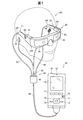
FIG. 1 is an explanatory diagram showing an external configuration of the head-mounted
頭部装着型表示装置100は、使用者の頭部に装着された状態において使用者に虚像を視認させる画像表示部20と、画像表示部20を制御する制御部10(コントローラー10)と、を備えている。
The head-mounted
画像表示部20は、使用者の頭部に装着される装着体であり、本実施形態では眼鏡形状を有している。画像表示部20は、右保持部21と、右表示駆動部22と、左保持部23と、左表示駆動部24と、右光学像表示部26と、左光学像表示部28と、10軸センサー66と、を含んでいる。右光学像表示部26および左光学像表示部28は、それぞれ、使用者が画像表示部20を装着した際に使用者の右および左の眼前に位置するように配置されている。右光学像表示部26の一端と左光学像表示部28の一端とは、使用者が画像表示部20を装着した際の使用者の眉間に対応する位置で、互いに接続されている。
The
右保持部21は、右光学像表示部26の他端である端部ERから、使用者が画像表示部20を装着した際の使用者の側頭部に対応する位置にかけて、延伸して設けられた部材である。同様に、左保持部23は、左光学像表示部28の他端である端部ELから、使用者が画像表示部20を装着した際の使用者の側頭部に対応する位置にかけて、延伸して設けられた部材である。右保持部21および左保持部23は、眼鏡のテンプル(つる)のようにして、使用者の頭部に画像表示部20を保持する。
The
右表示駆動部22と左表示駆動部24とは、使用者が画像表示部20を装着した際の使用者の頭部に対向する側に配置されている。なお、以降では、右保持部21および左保持部23を総称して単に「保持部」とも呼び、右表示駆動部22および左表示駆動部24を総称して単に「表示駆動部」とも呼び、右光学像表示部26および左光学像表示部28を総称して単に「光学像表示部」とも呼ぶ。
The right
表示駆動部22,24は、液晶ディスプレイ241,242(Liquid Crystal Display、以下「LCD241,242」とも呼ぶ)や投写光学系251,252等を含む(図2参照)。表示駆動部22,24の構成の詳細は後述する。光学部材としての光学像表示部26,28は、導光板261,262(図2参照)と調光板とを含んでいる。導光板261,262は、光透過性の樹脂材料等によって形成され、表示駆動部22,24から出力された画像光を使用者の眼に導く。調光板は、薄板状の光学素子であり、使用者の眼の側とは反対の側である画像表示部20の表側を覆うように配置されている。調光板は、導光板261,262を保護し、導光板261,262の損傷や汚れの付着等を抑制する。また、調光板の光透過率を調整することによって、使用者の眼に入る外光量を調整して虚像の視認のしやすさを調整できる。なお、調光板は省略可能である。
The
10軸センサー66は、加速度(3軸)、角速度(3軸)、地磁気(3軸)、および、気圧(1軸)を検出するセンサーである。10軸センサー66は、画像表示部20における表示駆動部22の近くに内蔵されており、画像表示部20が使用者の頭部に装着されているときには、使用者の頭部の動きや位置(以下、単に「画像表示部20の状態」とも呼ぶ)を検出する。なお、10軸センサー66によって検出される画像表示部20の状態は、請求項における装置状態に相当する。請求項における情報処理装置の装置状態とは、情報処理装置の一部の位置と向きとの少なくとも一方を含む。例えば、頭部装着型表示装置100の一部である画像表示部20の位置が変化し、頭部装着型表示装置100における画像表示部20以外の装置(例えば、制御部10)の位置および向きが変化していない場合であっても、請求項における情報処理装置の位置が変化した場合に相当する。
The ten-
画像表示部20は、さらに、画像表示部20を制御部10に接続するための接続部40を有している。接続部40は、制御部10に接続される本体コード48と、右コード42と、左コード44と、連結部材46と、を含んでいる。右コード42と左コード44とは、本体コード48が2本に分岐したコードである。右コード42は、右保持部21の延伸方向の先端部APから右保持部21の筐体内に挿入され、右表示駆動部22に接続されている。同様に、左コード44は、左保持部23の延伸方向の先端部APから左保持部23の筐体内に挿入され、左表示駆動部24に接続されている。連結部材46は、本体コード48と、右コード42および左コード44と、の分岐点に設けられ、イヤホンプラグ30を接続するためのジャックを有している。イヤホンプラグ30からは、右イヤホン32および左イヤホン34が延伸している。
The
画像表示部20と制御部10とは、接続部40を介して各種信号の伝送を行なう。本体コード48における連結部材46とは反対側の端部と、制御部10と、のそれぞれには、互いに嵌合するコネクター(図示しない)が設けられている。本体コード48のコネクターと制御部10のコネクターとの嵌合/嵌合解除により、制御部10と画像表示部20とが接続されたり切り離されたりする。右コード42と、左コード44と、本体コード48とには、例えば、金属ケーブルや光ファイバーを採用できる。
The
制御部10は、頭部装着型表示装置100を制御するための装置である。制御部10は、決定キー11と、点灯部12と、表示切替キー13と、トラックパッド14と、輝度切替キー15と、方向キー16と、メニューキー17と、電源スイッチ18と、加速度センサー19と、を含んでいる。決定キー11は、押下操作を検出して、制御部10で操作された内容を決定する信号を出力する。点灯部12は、頭部装着型表示装置100の動作状態を、その発光状態によって通知する。頭部装着型表示装置100の動作状態としては、例えば、電源のON/OFF等がある。点灯部12としては、例えば、LED(Light Emitting Diode)が用いられる。表示切替キー13は、押下操作を検出して、例えば、コンテンツ動画の表示モードを3Dと2Dとに切り替える信号を出力する。トラックパッド14は、トラックパッド14の操作面上での使用者の指の操作を検出して、検出内容に応じた信号を出力する。トラックパッド14としては、静電式や圧力検出式、光学式といった種々のトラックパッドを採用できる。輝度切替キー15は、押下操作を検出して、画像表示部20の輝度を増減する信号を出力する。方向キー16は、上下左右方向に対応するキーへの押下操作を検出して、検出内容に応じた信号を出力する。電源スイッチ18は、スイッチのスライド操作を検出することで、頭部装着型表示装置100の電源投入状態を切り替える。加速度センサー19は、制御部10に作用する加速度(例えば、重力加速度)を取得する。本実施形態では、加速度センサー19は、0.5秒間に1回、定期的に、制御部10に作用する加速度を取得する。
The
図2は、頭部装着型表示装置100の構成を機能的に示すブロック図である。図2に示すように、制御部10は、記憶部120と、電源130と、操作部135と、CPU140と、インターフェイス180と、送信部51(Tx51)および送信部52(Tx52)と、を有している。操作部135は、使用者による操作を受け付け、決定キー11、表示切替キー13、トラックパッド14、輝度切替キー15、方向キー16、メニューキー17、電源スイッチ18、および、加速度センサー19から構成されている。
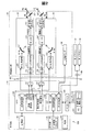
FIG. 2 is a block diagram functionally showing the configuration of the head-mounted
電源130は、頭部装着型表示装置100の各部に電力を供給する。電源130としては、例えば二次電池を用いることができる。記憶部120は、種々のコンピュータープログラムを格納している。記憶部120は、ROMやRAM等によって構成されている。CPU140は、記憶部120に格納されているコンピュータープログラムを読み出して実行することにより、オペレーティングシステム150(OS150)、表示制御部190、方向判定部166、画像処理部160、音声処理部170、および、入出力変換部169として機能する。
The
本実施形態で用いられるOS150は、アンドロイド(Android(登録商標))である。アンドロイドでは、複数のセンサーから検出されたそれぞれの検出結果に対応させて複数の制御を行なうことができない。なお、本実施形態では、OS150として、アンドロイドを用いたが、他の実施形態では、他のOSが用いられてもよい。
The
表示制御部190は、右表示駆動部22および左表示駆動部24を制御する制御信号を生成する。具体的には、表示制御部190は、制御信号により、右LCD制御部211による右LCD241の駆動ON/OFF、右バックライト制御部201による右バックライト221の駆動ON/OFF、左LCD制御部212による左LCD242の駆動ON/OFF、左バックライト制御部202による左バックライト222の駆動ON/OFFなど、を個別に制御する。これにより、表示制御部190は、右表示駆動部22および左表示駆動部24のそれぞれによる画像光の生成および射出を制御する。例えば、表示制御部190は、右表示駆動部22および左表示駆動部24の両方に画像光を生成させたり、一方のみに画像光を生成させたり、両方共に画像光を生成させなかったりする。表示制御部190は、右LCD制御部211と左LCD制御部212とに対する制御信号のそれぞれを、送信部51および52を介して送信する。また、表示制御部190は、右バックライト制御部201と左バックライト制御部202とに対する制御信号のそれぞれを送信する。
The
方向判定部166は、10軸センサー66によって特定された画像表示部20の向きに基づいて、使用者の視線方向を特定する。本実施形態では、視線方向が変化した場合に、方向判定部166は、所定の単位時間における変化前の視線方向と変化後の視線方向とがなす角度の変化(以下、「変化角度」とも呼ぶ)が閾値以上であるか否かを判定する。なお、方向判定部166および10軸センサー66は、請求項における第2の検出部に相当する。
The
画像処理部160は、コンテンツに含まれる画像信号を取得する。画像処理部160は、取得した画像信号から、垂直同期信号VSyncや水平同期信号HSync等の同期信号を分離する。また、画像処理部160は、分離した垂直同期信号VSyncや水平同期信号HSyncの周期に応じて、PLL(Phase Locked Loop)回路等(図示しない)を利用してクロック信号PCLKを生成する。画像処理部160は、同期信号が分離されたアナログ画像信号を、A/D変換回路等(図示しない)を用いてディジタル画像信号に変換する。その後、画像処理部160は、変換後のディジタル画像信号を、対象画像の画像データ(RGBデータ)として、1フレームごとに記憶部120内のDRAMに格納する。なお、画像処理部160は、必要に応じて、画像データに対して、解像度変換処理、輝度、彩度の調整といった種々の色調補正処理、キーストーン補正処理等の画像処理を実行してもよい。
The
画像処理部160は、生成されたクロック信号PCLK、垂直同期信号VSync、水平同期信号HSync、記憶部120内のDRAMに格納された画像データData、のそれぞれを、送信部51、52を介して送信する。なお、送信部51を介して送信される画像データDataを「右眼用画像データ」とも呼び、送信部52を介して送信される画像データDataを「左眼用画像データ」とも呼ぶ。送信部51、52は、制御部10と画像表示部20との間におけるシリアル伝送のためのトランシーバーとして機能する。
The
また、画像処理部160は、方向判定部166によって特定された使用者の視線方向に基づいて、画像表示部20に表示させる表示画像の各種制御を行なう。本実施形態では、画像処理部160は、方向判定部166によって判定された視線方向の変化角度によって、画像表示部20に表示している画像の表示有無を制御する。例えば、視線方向の変化角度が閾値以上の場合には、画像処理部160は、画像表示部20に表示されていた表示画像を非表示にする。
Further, the
音声処理部170は、コンテンツに含まれる音声信号を取得し、取得した音声信号を増幅して、連結部材46に接続された右イヤホン32内のスピーカー(図示しない)および左イヤホン34内のスピーカー(図示しない)に対して供給する。なお、例えば、Dolby(登録商標)システムを採用した場合、音声信号に対する処理がなされ、右イヤホン32および左イヤホン34のそれぞれからは、例えば周波数等が変えられた異なる音が出力される。
The
入出力変換部169は、使用者による操作入力に応じた信号と操作部135が形成されている制御部10に作用する加速度を示す信号とを取得して、取得した信号に基づいてOS150へと出力信号を送信するデバイスドライバーである。操作入力に応じた信号としては、例えば、操作部135におけるトラックパッド14、方向キー16、電源スイッチ18、に対する操作入力がある。入出力変換部169は、加速度センサー19が取得した加速度に基づいて、操作部135の向きと重力方向とを入力として特定する。入出力変換部169は、操作部135の向きと重力方向とがなす角度に基づいて、入力を出力信号に変換するための変換角度を決定する。変換角度とは、入力としての操作部135の向きと重力方向とがなす角度に対して、入出力変換部169がOS150へと出力信号を送信する際に補正する角度のことである。入出力変換部169は、操作部135のトラックパッド14が受け付けた入力を、変換角度に基づいて出力信号に変換し、OS150へと変換した出力信号を送信する。加速度センサー19が取得した信号は、入出力変換部169に送信され、OS150には送信されない。なお、変換角度の詳細については、後述する。変換角度は、請求項における第1の規則および第2の規則に相当する。また、加速度センサー19および入出力変換部169は、請求項における第1の検出部に相当する。
The input / output conversion unit 169 acquires a signal corresponding to an operation input by the user and a signal indicating an acceleration acting on the
インターフェイス180(図2)は、制御部10に対して、コンテンツの供給元となる種々の外部機器OAを接続するためのインターフェイスである。外部機器OAとしては、例えば、パーソナルコンピューター(PC)や携帯電話端末、ゲーム端末等、がある。インターフェイス180としては、例えば、USBインターフェイス、マイクロUSBインターフェイス、メモリーカード用インターフェイス等、を用いることができる。
The interface 180 (FIG. 2) is an interface for connecting various external devices OA that are content supply sources to the
画像表示部20は、右表示駆動部22と、左表示駆動部24と、右光学像表示部26としての右導光板261と、左光学像表示部28としての左導光板262と、10軸センサー66と、を備えている。
The
右表示駆動部22は、受信部53(Rx53)と、光源として機能する右バックライト制御部201(右BL制御部201)および右バックライト221(右BL221)と、表示素子として機能する右LCD制御部211および右LCD241と、右投写光学系251と、を含んでいる。右バックライト制御部201と右バックライト221とは、光源として機能する。右LCD制御部211と右LCD241とは、表示素子として機能する。なお、右バックライト制御部201と、右LCD制御部211と、右バックライト221と、右LCD241と、を総称して「画像光生成部」とも呼ぶ。
The right
受信部53は、制御部10と画像表示部20との間におけるシリアル伝送のためのレシーバーとして機能する。右バックライト制御部201は、入力された制御信号に基づいて、右バックライト221を駆動する。右バックライト221は、例えば、LEDやエレクトロルミネセンス(EL)等の発光体である。右LCD制御部211は、受信部53を介して入力されたクロック信号PCLKと、垂直同期信号VSyncと、水平同期信号HSyncと、右眼用画像データと、に基づいて、右LCD241を駆動する。右LCD241は、複数の画素をマトリクス状に配置した透過型液晶パネルである。
The receiving
右投写光学系251は、右LCD241から射出された画像光を並行状態の光束にするコリメートレンズによって構成される。右光学像表示部26としての右導光板261は、右投写光学系251から出力された画像光を、所定の光路に沿って反射させつつ使用者の右眼REに導く。なお、右投写光学系251と右導光板261とを総称して「導光部」とも呼ぶ。
The right projection
左表示駆動部24は、右表示駆動部22と同様の構成を有している。左表示駆動部24は、受信部54(Rx54)と、光源として機能する左バックライト制御部202(左BL制御部202)および左バックライト222(左BL222)と、表示素子として機能する左LCD制御部212および左LCD242と、左投写光学系252と、を含んでいる。左バックライト制御部202と左バックライト222とは、光源として機能する。左LCD制御部212と左LCD242とは、表示素子として機能する。なお、左バックライト制御部202と、左LCD制御部212と、左バックライト222と、左LCD242と、を総称して「画像光生成部」とも呼ぶ。また、左投写光学系252は、左LCD242から射出された画像光を並行状態の光束にするコリメートレンズによって構成される。左光学像表示部28としての左導光板262は、左投写光学系252から出力された画像光を、所定の光路に沿って反射させつつ使用者の左眼LEに導く。なお、左投写光学系252と左導光板262とを総称して「導光部」とも呼ぶ。
The left
図3は、画像光生成部によって画像光が射出される様子を示す説明図である。右LCD241は、マトリクス状に配置された各画素位置の液晶を駆動することによって、右LCD241を透過する光の透過率を変化させることにより、右バックライト221から照射される照明光ILを、画像を表わす有効な画像光PLへと変調する。左側についても同様である。なお、図3のように、本実施形態ではバックライト方式を採用したが、フロントライト方式や、反射方式を用いて画像光を射出する構成としてもよい。
FIG. 3 is an explanatory diagram illustrating a state in which image light is emitted by the image light generation unit. The
A−2.表示画像制御処理:
図4は、表示画像制御処理の流れを示す説明図である。表示画像制御処理は、画像表示部20に画像が表示された後に、10軸センサー66および方向判定部166によって特定された使用者の視線方向の変化角度と、入出力変換部169が変換した出力信号と、に応じて画像表示部20に表示される表示画像が制御される処理である。
A-2. Display image control processing:
FIG. 4 is an explanatory diagram showing the flow of the display image control process. In the display image control process, after the image is displayed on the
表示画像制御処理では、初めに、画像表示部20が、画像処理部160から送信された画像信号に基づいて画像を表示する(ステップS11)。次に、10軸センサー66は、画像表示部20の状態を検出する(ステップS12)。本実施形態では、10軸センサー66が画像表示部20の加速度を検出して、検出された加速度に応じた表示画像の制御が行なわれる。次に、方向判定部166は、検出された加速度に基づいて使用者の視線方向を特定する(ステップS13)。次に、方向判定部166は、視線方向が変化しているか否かを判定する(ステップS14)。視線方向の変化角度が閾値以上である場合には、視線方向が変化していると判定され(ステップS14:YES)、画像処理部160は、画像表示部20に表示していた表示画像を非表示にする。
In the display image control process, first, the
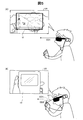
図5は、視線方向の変化前後で使用者が視認する視野VRの概略を示す説明図である。図5(A)には、使用者の視線方向が変化する前に使用者が視認する視野VRが示されている。図5(A)に示すように、使用者は、表示画像VIを視認している。表示画像VIには、トラックパッド14に触れた指に連動して動くポインターPOが含まれている。使用者の視線方向ED1は、水平方向と同じ方向である。図5(B)には、使用者の視線方向が変化した後に使用者が視認する視野VRが示されている。図5(B)に示すように、使用者は、水平方向ではなく、視線を下側に落として制御部10を注視している。この場合に、使用者の視線方向ED1は、視線方向ED2へと変化している。視線方向ED1と視線方向ED2とがなす角度α1は、予め設定された閾値以上の変化角度であるため、画像処理部160は、使用者の視線方向が変化した後では、表示画像VIを非表示にする。
FIG. 5 is an explanatory diagram showing an outline of the visual field VR visually recognized by the user before and after the change in the line-of-sight direction. FIG. 5A shows a visual field VR visually recognized by the user before the user's line-of-sight direction changes. As shown in FIG. 5A, the user visually recognizes the display image VI. The display image VI includes a pointer PO that moves in conjunction with a finger touching the
次に、方向判定部166は、使用者の視線方向が変化したと判定されてから所定の時間(例えば、5秒間)が経過したか否かを判定する(図4のステップS16)。所定の時間が経過していないと判定された場合には(ステップS16:NO)、画像処理部160は、所定の時間が経過するのを待つ。所定の時間が経過したと判定された場合には(ステップS16:YES)、画像処理部160は、再び、表示画像VIを画像表示部20に表示する(ステップS17)。次に、画像表示部20に表示画像VIが表示されている場合(ステップS17)、または、ステップS14の処理において視線方向の変化角度が閾値未満であり、視線方向が変化していないと判定された場合には(ステップS14:NO)、制御部10は、操作部135に対する操作の受付を監視する(ステップS18)。操作の受付が検出されなかった場合には(ステップS18:NO)、ステップS12以降の処理が繰り返される。使用者の指がトラックパッド14に触れるといったような操作の受付が検出された場合には(ステップS18:YES)、制御部10は、操作入力処理を行なう(ステップS19)。
Next, the
図6は、操作入力処理の流れを示す説明図である。操作入力処理では、初めに、加速度センサー19が、操作部135が形成されている制御部10に作用する加速度を取得する(ステップS31)。次に、入出力変換部169は、取得された加速度と重力方向との関係に基づいて変換角度を特定する(ステップS32)。次に、制御部10は、操作部135のトラックパッド14に触れている状態で使用者の指の位置が変化するなどの操作(以下、単に「ポインター操作」とも呼ぶ)の受付を監視する(ステップS33)。ポインター操作が受け付けられた場合には(ステップS33:YES)、画像処理部160は、受け付けたポインター操作に基づいて、表示画像VIのポインターPOの表示位置を変更する(ステップS34)。
FIG. 6 is an explanatory diagram showing the flow of the operation input process. In the operation input process, first, the
図7および図8は、ポインター操作によるポインターPOの表示位置の変更についての説明図である。図7には、制御部10において、トラックパッド14の中心O1と決定キー11の中心O2とを通る直線L1と、重力方向DGと、トラックパッド14上で動かされる使用者の人差し指FFの操作方向DR1と、が示されている。図7に示すように、重力方向DGと操作方向DR1とは、同じ方向である。また、図7には、ポインター操作を受け付けた場合の使用者の視野VRが示されている。本実施形態では、初期設定として、トラックパッド14における直線L1に沿った中心O1から中心O2への基準方向D0と重力方向DGとが同じ方向の場合に変換角度が0であると設定されている。そのため、操作方向DR1が基準方向D0と同じ方向である場合には変換角度が0度であるため、入出力変換部169は、操作方向DR1に沿った人差し指FFの動きを、同じように、操作方向DR1に沿った動きとして出力する。
7 and 8 are explanatory diagrams for changing the display position of the pointer PO by the pointer operation. In FIG. 7, in the
図8には、基準方向D0と重力方向DGとが同じ方向ではなく、制御部10が重力方向に対して初期設定と比べて傾いている場合に、入出力変換部169が補正して出力する例が示されている。図8に示すように、制御部10が傾いているため、重力方向DGと基準方向D0とは、角度β1を形成する。なお、角度β1は、60度である。この場合に、入出力変換部169は、重力方向DGを基準として重力方向DGから時計回りを正の角度として、基準方向D0に沿った操作方向DR1の人差し指FFの動きを、変換角度である角度β1の分だけ補正する。すなわち、トラックパッド14に対する操作方向DR1の相対方向は、基準方向D0と同じであっても、入出力変換部169が変換した後の出力信号は、加速度センサー19によって取得された重力方向DGによって異なる。OS150および画像処理部160は、入出力変換部169からの出力信号を受信して、図8の表示画像VIに示すように、ポインターPOの表示位置を変更する。
In FIG. 8, when the reference direction D0 and the gravity direction DG are not the same direction and the
表示画像VIにおけるポインターPOの表示位置が変更される(図6のステップS34)、または、ポインター操作が受け付けられなかった場合には(ステップS33:NO)、制御部10は、操作部135における各種ボタンに対する所定の操作(以下、「ボタン操作」とも呼ぶ)の受付を監視する(ステップS35)。所定のボタン操作が受け付けられた場合には(ステップS35:YES)、制御部10は、ボタン操作に応じた所定の制御を行なう(ステップS36)。所定の制御が行なわれる(ステップS36)、または、ボタン操作が受け付けられなかった場合には(ステップS35:NO)、制御部10は、操作入力処理を終了する操作の受付を監視する(ステップS37)。操作入力処理を終了する操作が受け付けられない場合には(ステップS37:NO)、制御部10は、引き続き、ステップS31以降の処理を行なう。操作入力処理を終了する操作が受け付けられた場合には(ステップS37:YES)、制御部10は、操作入力処理を終了する。
When the display position of the pointer PO in the display image VI is changed (step S34 in FIG. 6) or when the pointer operation is not accepted (step S33: NO), the
操作入力処理が終了すると(図4のステップS19)、制御部10は、画像の表示を終了する操作の受付を監視する(ステップS20)。画像の表示を終了する操作が受け付けられない場合には(ステップS20:NO)、制御部10は、引き続き、ステップS12以降の処理を行なう。画像の表示を終了する操作が受け付けられた場合には(ステップS20:YES)、制御部10は、表示画像制御処理を終了する。
When the operation input process ends (step S19 in FIG. 4), the
以上説明したように、本実施形態における頭部装着型表示装置100では、加速度センサー19によって操作部135が形成された制御部10に作用する加速度が取得され、入出力変換部169は、制御部10に作用する重力加速度に基づいて変換角度を特定し、変換角度に基づいて、操作部135が受け付けた入力を変換した出力信号をOS150へと送信する。また、10軸センサー66および方向判定部166が使用者の視線方向を特定し、OS150および画像処理部160は、視線方向の変化に応じて画像表示部20に表示される表示画像VIの制御を行なう。そのため、本実施形態における頭部装着型表示装置100では、複数のセンサーの検出結果のそれぞれに対応して異なる制御が行なわれるため、頭部装着型表示装置100に対して多様な制御を行なうことができる。
As described above, in the head-mounted
また、本実施形態における頭部装着型表示装置100では、加速度センサー19は、操作部135が形成されている制御部10に形成され、制御部10に作用する重力加速度を取得する。そのため、本実施形態における頭部装着型表示装置100では、操作部135の向きではなく、重力方向の向きを基準とした使用者の入力に対応した頭部装着型表示装置100の制御が行なわれるため、使用者は操作部135の向きにかかわらず重力方向を基準とした入力を行なうことができ、使用者の操作性が向上する。
In the head-mounted
また、本実施形態における頭部装着型表示装置100では、画像表示部20に内蔵された10軸センサー66および方向判定部166によって特定された使用者の視線方向の変化角度が閾値以上の場合に、画像処理部160が画像表示部20に表示していた表示画像VIを非表示にする。そのため、本実施形態における頭部装着型表示装置100では、使用者の視線方向に応じて表示画像VIが制御されるため、使用者の状況に応じて、使用者に視認される風景等が異なり、使用者の利便性が向上する。
Further, in the head-mounted
また、本実施形態における頭部装着型表示装置100では、加速度センサー19が0.5秒間に1回、定期的に、操作部135が形成された制御部10に作用する加速度を取得する。そのため、本実施形態における頭部装着型表示装置100では、常に制御部10に作用する加速度が取得される必要がなく、制御部10にかかる負荷を抑制した上で、使用者の利便性を向上させることができる。
Further, in the head-mounted
また、本実施形態における頭部装着型表示装置100では、OS150および画像処理部160によって画像表示部20に表示される表示画像VIが制御され、入出力変換部169はデバイスドライバーによって構成されている。そのため、本実施形態における頭部装着型表示装置100では、操作部135のみに対応させた加速度センサー19および入出力変換部169が採用されることで、CPU140の負荷を低減し、OS150等のソフトウェアを変更する必要がなく、頭部装着型表示装置100の開発期間を短縮できる。
In the head-mounted
B.変形例:
なお、この発明は上記実施形態に限られるものではなく、その要旨を逸脱しない範囲において種々の態様において実施することが可能であり、例えば、次のような変形も可能である。
B. Variations:
In addition, this invention is not limited to the said embodiment, It can implement in a various aspect in the range which does not deviate from the summary, For example, the following deformation | transformation is also possible.
B1.変形例1:
上記実施形態では、画像表示部20に内蔵された10軸センサー66が画像表示部20の状態を検出し、制御部10に含まれる加速度センサー19が制御部10に作用する加速度を取得したが、各センサーの態様については種々変形可能である。例えば、制御部10および画像表示部20とは異なる部分に設置されたカメラによって、制御部10の向きおよび画像表示部20の位置の変化が検出されて、当該検出結果に基づいて画像表示部20の表示画像VIが制御されてもよい。
B1. Modification 1:
In the above embodiment, the 10-
また、画像表示部20に内蔵された10軸センサー66の代わりに、制御部10に加速度センサー19とは別に10軸センサーが内蔵されてもよい。例えば、トラックパッド14への入力が加速度センサー19および入出力変換部169によって変換して出力され、制御部10に内蔵された10軸センサーが検出した加速度の変化によって、表示画像VIに含まれるアイコンの決定等の操作が行なわれてもよい。この変形例の頭部装着型表示装置100では、使用者は感覚的に各種操作を行なうことができ、使用者の利便性が向上する。
Instead of the 10-
また、上記実施形態では、画像表示部20の10軸センサー66が検出した変化角度によって、画像表示部20の表示画像VIの表示と非表示とが切り替えられたが、10軸センサー66の検出結果によって制御される頭部装着型表示装置100の内容については、種々変形可能である。例えば、使用者が下を向いている場合には、表示画像VIが形成される領域の中で上側に表示され、使用者が上を向いている場合には、表示画像VIが当該領域の下側に表示されてもよい。すなわち、10軸センサー66によって検出される画像表示部20の向きによって、表示画像VIが制御されてもよい。また、頭部装着型表示装置100が制御される内容として、画像表示部20の表示画像VIの代わりに、音声処理部170およびイヤホン32,34によって音声が出力されてもよい。また、制御部10は、画像表示部20を振動させる制御を行なってもよい。
In the above embodiment, the display image VI of the
また、上記実施形態では、変換角度に基づいてポインター操作を変換されてポインターPOの表示位置が変更されたが、操作部135の向きに基づいて入力が出力へと変換される規則については、これに限られず、種々変形可能である。例えば、加速度センサー19の代わりにジャイロセンサーが制御部10に内蔵され、操作部135の向きの変化として、制御部10の角速度が検出され、角速度に基づいて、表示画像VIが制御されてもよい。この場合に、制御部10自体が1つの操作用スティックとして、左右および上下に振られることで、表示画像VIにおけるポインターPOの表示位置が変更される。この変形例では、使用者は、操作部135を含む制御部10全体を1つの操作部として操作できるため、直感的な操作を行ないやすく、使用者の操作性や利便性が向上する。
Further, in the above embodiment, the pointer operation is converted based on the conversion angle and the display position of the pointer PO is changed. However, the rules for converting the input to the output based on the direction of the
また、上記実施形態では、操作部135の基準方向D0と重力方向との角度β1に基づいて変換角度が特定されたが、操作部135の向きに基づいて特定されるのは変換角度に限られず、種々変形可能である。例えば、操作部135のトラックパッド14に直交する軸と重力加速度の向きとの角度によって、操作部135が操作を受付可能な状態と受付不可能な状態とが切り替えられてもよい。具体的には、トラックパッド14の裏側から表側へと向かう直交軸の向きと重力加速度の向きとがなす角度が90度以下の場合、すなわち、トラックパッド14の操作面が重力加速度の向きを向いている場合には、使用者が操作を行なわないと判断されて、入出力変換部169は、操作を受け付け不可能な省電力モードに設定してもよい。逆に、直交軸の向きと重力加速度の向きとがなす角度が90度よりも大きい場合には、使用者が操作を行なう予定であると判断されて、入出力変換部169は、操作を受け付け可能な待機モードに設定してもよい。この変形例では、トラックパッド14の操作面が重力加速度の向きを向いている場合に、入力を受け付ける待機モードにならなくてもよいので、頭部装着型表示装置100における電力の消費を抑制できる。なお、この変形例では、直交軸と重力加速度の向きとがなす角度として、90度といった角度を例に挙げて説明したが、角度については、これに限られず、種々変形可能である。操作部135が操作されることで、角度が任意に設定されてもよい。この変形例における直交軸の向きと重力加速度の向きとがなす角度が90度以下の状態は、請求項における第1の状態に相当し、当該角度が90度よりも大きい状態は、請求項における第2の状態に相当する。
In the above-described embodiment, the conversion angle is specified based on the angle β1 between the reference direction D0 and the gravity direction of the
また、操作部135の向きによって入力を出力へと変換する規則は、所定の操作を受け付けることによって任意に変更されてもよい。例えば、操作部135の向きによって特定される変換角度に基づく変換と、直交軸の向きと重力加速度の向きとがなす角度に基づく状態の設定と、が操作部135によって受け付けられた操作に基づいて変更されてもよい。また、画像表示部20に形成された赤外線発光部が発光した赤外線が、トラックパッド14の近くに形成された赤外線受光部に受光されることで、直交軸の向きと重力加速度の向きが同じ場合でも、操作部135が操作を受付可能な状態に設定されてもよい。この場合には、例えば、使用者が寝転んだ状態でも頭部装着型表示装置100を操作でき、使用者の操作性および利便性が向上する。なお、この変形例における赤外線発光部および赤外線受光部に代えて、画像表示部20に形成されたカメラによって制御部10が撮像されることで、同様の状態に設定されてもよい。なお、画像表示部20と操作部135の向きとの位置関係に応じて、入力を出力へと変換する規則が変更される設定については、種々変形可能である。この変形例における赤外線発光部が発光する赤外線が赤外線受光部に受光された状態は、請求項における第1の状態に相当し、当該赤外線が赤外線受光部に受光されていない状態は、請求項における第2の状態に相当する。
Further, the rule for converting the input into the output depending on the direction of the
B2.変形例2:
上記実施形態では、入出力変換部169は、基準方向D0と重力方向DGとがなす変換角度の角度β1の分だけ出力を補正したが、補正する変換角度については種々変形可能である。例えば、入出力変換部169は、基準方向D0と重力方向DGとのなす角度β1によって、4通りの変換角度に基づいて出力を補正してもよい。角度β1が0度以上45度以下または315度以上360度未満の場合には、入出力変換部169は、基準方向D0と重力方向DGとが同じ方向とみなして、変換角度を0に設定する。同じように、入出力変換部169は、角度β1が45度よりも大きく135度以下の場合には、変換角度を90度に設定し、角度β1が135度よりも大きく225度未満の場合には、変換角度を180度に設定し、角度β1が225度以上315度未満の場合には、変換角度を270度に設定してもよい。この変形例では、変換角度が4通りしかないため、トラックパッド14が受け付けた入力を出力へと補正するのが簡便であり、システムの付加を低減でき、また、加速度センサー19が制御部10に作用する加速度を取得する頻度を少なくできる。また、トラックパッド14が受け付けた入力と共に、変換角度に基づいて、方向キー16が受け付けた入力を出力へと補正してもよい。この変形例では、入出力変換部169は、角度β1を4つの範囲に分け、角度β1に応じて、トラックパッド14が受け付けた入力を出力へと補正する。
B2. Modification 2:
In the above embodiment, the input / output conversion unit 169 corrects the output by the angle β1 of the conversion angle formed by the reference direction D0 and the gravity direction DG, but the conversion angle to be corrected can be variously modified. For example, the input / output conversion unit 169 may correct the output based on the four conversion angles by the angle β1 formed by the reference direction D0 and the gravity direction DG. When the angle β1 is not less than 0 degrees and not more than 45 degrees or not less than 315 degrees and less than 360 degrees, the input / output conversion unit 169 regards the reference direction D0 and the gravity direction DG as the same direction and sets the conversion angle to 0. . Similarly, the input / output conversion unit 169 sets the conversion angle to 90 degrees when the angle β1 is greater than 45 degrees and equal to or less than 135 degrees, and the angle β1 is greater than 135 degrees and less than 225 degrees. May set the conversion angle to 180 degrees, and if the angle β1 is not less than 225 degrees and less than 315 degrees, the conversion angle may be set to 270 degrees. In this modification, since there are only four conversion angles, it is easy to correct the input received by the
また、上記実施形態では、基準方向D0と重力方向DGとが異なる場合に、角度β1の分だけ出力が補正されたが、基準方向D0と重力方向DGとが異なっている場合でも、出力の補正が行なわれなくてもよい。例えば、操作部135のメニューキー17等が所定の時間以上押下される(以下、「長押し」とも呼ぶ)ことで、長押しされ始めた時点での変換角度が継続されてもよい。この変形例では、例えば、使用者が座っている状態から横たわった状態に変化して、横たわった状態で操作部135が操作される場合でも、使用者に対する操作部135の操作を受け付ける相対方向が変化しないため、使用者の利便性が向上する。
Further, in the above embodiment, when the reference direction D0 and the gravity direction DG are different, the output is corrected by the angle β1, but even when the reference direction D0 and the gravity direction DG are different, the output is corrected. May not be performed. For example, when the
B3.変形例3:
上記実施形態では、入出力変換部169は、OS150へと出力信号を送信するデバイスドライバーであるとしたが、入出力変換部169の構成は、種々変形可能である。例えば、入出力変換部169は、システムの階層構造において、デバイスドライバーとOS150との間に構成され、ハードウェアとソフトウェアの間に入るミドルウェア(例えば、HAL(Hardware Abstraction Layer))に構成されてもよい。なお、請求項におけるオペレーティングシステムとは、操作部135が受け付けた入力や表示画像VIを表示するといった入出力機能やディスクやメモリーの管理など、多くのアプリケーションソフトから共通して利用される基本的な機能を提供し、コンピュータシステム全体を管理するソフトウェアのことをいう。また、請求項におけるデバイスドライバーとは、コンピューター内部に装着された装置や、外部に接続した機器を制御または操作するためのソフトウェアのことをいう。また、請求項におけるミドルウェアとは、OS150上で動作し、アプリケーションソフトに対してOS150よりも高度で具体的な機能を提供するソフトウェアのことをいう。
B3. Modification 3:
In the above embodiment, the input / output conversion unit 169 is a device driver that transmits an output signal to the
また、上記実施形態では、操作部を備える情報処理装置として、頭部装着型表示装置100を例に挙げて説明したが、必ずしも頭部装着型表示装置である必要はなく、情報処理装置の態様としては種々変形可能である。例えば、情報処理装置は、画像表示部20の代わりに、モニターのように配置されたディスプレイに画像を表示させる装置を含む装置であってもよい。
In the above embodiment, the head-mounted
B4.変形例4:
上記実施形態では、制御部10に操作部135が形成されたが、操作部135の態様については種々変形可能である。例えば、制御部10とは別体で操作部135であるユーザーインターフェースがある態様でもよい。この場合に、操作部135は、電源130等が形成された制御部10とは別体であるため、小型化でき、使用者の操作性が向上する。
B4. Modification 4:
In the above embodiment, the
例えば、画像光生成部は、有機EL(有機エレクトロルミネッセンス、Organic Electro-Luminescence)のディスプレイと、有機EL制御部とを備える構成としてもよい。また、例えば、画像生成部は、LCDに代えて、LCOS(Liquid crystal on silicon, LCoS は登録商標)や、デジタル・マイクロミラー・デバイス等を用いることもできる。また、例えば、レーザー網膜投影型の頭部装着型表示装置100に対して本発明を適用することも可能である。
For example, the image light generation unit may include an organic EL (Organic Electro-Luminescence) display and an organic EL control unit. Further, for example, the image generation unit may use LCOS (Liquid crystal on silicon, LCoS is a registered trademark), a digital micromirror device, or the like instead of the LCD. Further, for example, the present invention can be applied to the laser-retinal projection head-mounted
また、例えば、頭部装着型表示装置100は、光学像表示部が使用者の眼の一部分のみを覆う態様、換言すれば、光学像表示部が使用者の眼を完全に覆わない態様のヘッドマウントディスプレイとしてもよい。また、頭部装着型表示装置100は、いわゆる単眼タイプのヘッドマウントディスプレイであるとしてもよい。また、頭部装着型表示装置100は、両眼タイプの光学透過型であるとしているが、本発明は、例えば、ビデオ透過型といった他の形式の頭部装着型表示装置にも同様に適用可能である。
Further, for example, the head-mounted
また、イヤホンは耳掛け型やヘッドバンド型が採用されてもよく、省略してもよい。また、例えば、自動車や飛行機等の車両に搭載される頭部装着型表示装置として構成されてもよい。また、例えば、ヘルメット等の身体防護具に内蔵された頭部装着型表示装置として構成されてもよい。 The earphone may be an ear-hook type or a headband type, or may be omitted. Further, for example, it may be configured as a head-mounted display device mounted on a vehicle such as an automobile or an airplane. For example, it may be configured as a head-mounted display device built in a body protective device such as a helmet.
B5.変形例5:
上記実施形態における頭部装着型表示装置100の構成は、あくまで一例であり、種々変形可能である。例えば、制御部10に設けられた方向キー16やトラックパッド14の一方を省略したり、方向キー16やトラックパッド14に加えてまたは方向キー16やトラックパッド14に代えて操作用スティック等の他の操作用インターフェイスを設けたりしてもよい。また、制御部10は、キーボードやマウス等の入力デバイスを接続可能な構成であり、キーボードやマウスから入力を受け付けるものとしてもよい。
B5. Modification 5:
The configuration of the head-mounted
また、画像表示部として、眼鏡のように装着する画像表示部20に代えて、例えば帽子のように装着する画像表示部といった他の方式の画像表示部を採用してもよい。また、イヤホン32,34や外景撮像カメラ61は、適宜省略可能である。また、上記実施形態では、画像光を生成する構成として、LCDと光源とを利用しているが、これらに代えて、有機ELディスプレイといった他の表示素子を採用してもよい。また、上記実施形態では、使用者の頭の動きを検出するセンサーとして10軸センサー66を利用しているが、これに代えて、加速度センサー、角速度センサー、地磁気センサー、および、気圧センサーのうちの1つまたは2つから構成されたセンサーを利用するとしてもよい。
As the image display unit, instead of the
図9は、変形例における頭部装着型表示装置の外観構成を示す説明図である。図9(A)の例の場合、図1に示した頭部装着型表示装置100との違いは、画像表示部20aが、右光学像表示部26に代えて右光学像表示部26aを備える点と、左光学像表示部28に代えて左光学像表示部28aを備える点とである。右光学像表示部26aは、上記実施形態の光学部材よりも小さく形成され、頭部装着型表示装置100aの装着時における使用者の右眼の斜め上に配置されている。同様に、左光学像表示部28bは、上記実施形態の光学部材よりも小さく形成され、頭部装着型表示装置100aの装着時における使用者の左眼の斜め上に配置されている。図9(B)の例の場合、図1に示した頭部装着型表示装置100との違いは、画像表示部20bが、右光学像表示部26に代えて右光学像表示部26bを備える点と、左光学像表示部28に代えて左光学像表示部28bを備える点とである。右光学像表示部26bは、上記実施形態の光学部材よりも小さく形成され、ヘッドマウントディスプレイの装着時における使用者の右眼の斜め下に配置されている。左光学像表示部28bは、上記実施形態の光学部材よりも小さく形成され、ヘッドマウントディスプレイの装着時における使用者の左眼の斜め下に配置されている。このように、光学像表示部は使用者の眼の近傍に配置されていれば足りる。また、光学像表示部を形成する光学部材の大きさも任意であり、光学像表示部が使用者の眼の一部分のみを覆う態様、換言すれば、光学像表示部が使用者の眼を完全に覆わない態様の頭部装着型表示装置100として実現できる。
FIG. 9 is an explanatory diagram illustrating an external configuration of a head-mounted display device according to a modification. In the case of the example of FIG. 9A, the difference from the head-mounted
また、上記実施形態において、頭部装着型表示装置100は、使用者の左右の眼に同じ画像を表わす画像光を導いて使用者に二次元画像を視認させるとしてもよいし、使用者の左右の眼に異なる画像を表わす画像光を導いて使用者に三次元画像を視認させるとしてもよい。
In the above-described embodiment, the head-mounted
また、上記実施形態において、ハードウェアによって実現されていた構成の一部をソフトウェアに置き換えるようにしてもよく、逆に、ソフトウェアによって実現されていた構成の一部をハードウェアに置き換えるようにしてもよい。例えば、上記実施形態では、画像処理部160や音声処理部170は、CPU140がコンピュータープログラムを読み出して実行することにより実現されるとしているが、これらの機能部はハードウェア回路により実現されるとしてもよい。
In the above embodiment, a part of the configuration realized by hardware may be replaced by software, and conversely, a part of the configuration realized by software may be replaced by hardware. Good. For example, in the above-described embodiment, the
また、本発明の機能の一部または全部がソフトウェアで実現される場合には、そのソフトウェア(コンピュータープログラム)は、コンピューター読み取り可能な記録媒体に格納された形で提供することができる。この発明において、「コンピューター読み取り可能な記録媒体」とは、フレキシブルディスクやCD−ROMのような携帯型の記録媒体に限らず、各種のRAMやROM等のコンピューター内の内部記憶装置や、ハードディスク等のコンピューターに固定されている外部記憶装置も含んでいる。 In addition, when part or all of the functions of the present invention are realized by software, the software (computer program) can be provided in a form stored in a computer-readable recording medium. In the present invention, the “computer-readable recording medium” is not limited to a portable recording medium such as a flexible disk or a CD-ROM, but an internal storage device in a computer such as various RAMs and ROMs, a hard disk, etc. It also includes an external storage device fixed to the computer.
また、上記実施形態では、図1および図2に示すように、制御部10と画像表示部20とが別々の構成として形成されているが、制御部10と画像表示部20との構成については、これに限られず、種々変形可能である。例えば、画像表示部20の内部に、制御部10に形成された構成の全てが形成されてもよいし、一部が形成されてもよい。また、上記実施形態における電源130が単独で形成されて、交換可能な構成であってもよいし、制御部10に形成された構成が重複して画像表示部20に形成されていてもよい。例えば、図2に示すCPU140が制御部10と画像表示部20との両方に形成されていてもよいし、制御部10に形成されたCPU140と画像表示部20に形成されたCPUとが行なう機能が別々に分けられている構成としてもよい。
Moreover, in the said embodiment, as shown in FIG. 1 and FIG. 2, the
また、制御部10がPCに内蔵されて、PCのモニターに代えて画像表示部20が使用される態様であってもよいし、制御部10と画像表示部20とが一体化して、使用者の衣服に取り付けられるウェアラブルコンピューターの態様であってもよい。
Further, the
本発明は、上記実施形態や変形例に限られるものではなく、その趣旨を逸脱しない範囲において種々の構成で実現することができる。例えば、発明の概要の欄に記載した各形態中の技術的特徴に対応する実施形態、変形例中の技術的特徴は、上述の課題の一部または全部を解決するために、あるいは、上述の効果の一部または全部を達成するために、適宜、差し替えや、組み合わせを行なうことが可能である。また、その技術的特徴が本明細書中に必須なものとして説明されていなければ、適宜、削除することが可能である。 The present invention is not limited to the above-described embodiments and modifications, and can be realized with various configurations without departing from the spirit of the present invention. For example, the technical features in the embodiments and the modifications corresponding to the technical features in each form described in the summary section of the invention are to solve some or all of the above-described problems, or In order to achieve part or all of the effects, replacement or combination can be performed as appropriate. Further, if the technical feature is not described as essential in the present specification, it can be deleted as appropriate.
10…制御部(操作部)
11…決定キー
12…点灯部
13…表示切替キー
14…トラックパッド
15…輝度切替キー
16…方向キー
17…メニューキー
18…電源スイッチ
19…加速度センサー(第1の検出部)
20…画像表示部(画像表示部)
21…右保持部
22…右表示駆動部
23…左保持部
24…左表示駆動部
26…右光学像表示部
28…左光学像表示部
30…イヤホンプラグ
32…右イヤホン
34…左イヤホン
40…接続部
42…右コード
44…左コード
46…連結部材
48…本体コード
51,52…送信部
53,54…受信部
61…外景撮像カメラ
66…10軸センサー(第2の検出部)
100…頭部装着型表示装置(情報処理装置)
120…記憶部
130…電源
135…操作部(操作部)
140…CPU
150…オペレーティングシステム(制御処理部)
160…画像処理部(制御処理部)
166…方向判定部(第2の検出部)
169…入出力変換部(第1の検出部、入出力変換部)
170…音声処理部
180…インターフェイス
190…表示制御部
201…右バックライト制御部
202…左バックライト制御部
211…右LCD制御部
212…左LCD制御部
221…右バックライト
222…左バックライト
241…右LCD
242…左LCD
251…右投写光学系
252…左投写光学系
261…右導光板
262…左導光板
VSync…垂直同期信号
HSync…水平同期信号
PCLK…クロック信号
O1…トラックパッドの中心
O2…決定キーの中心
L1…直線
VR…視野
VI…表示画像(画像光)
IL…照明光
PL…画像光
FF…人差し指
PO…ポインター
D0…基準方向
DG…重力方向
ED1,ED2…視線方向
DR1…操作方向
α1,β1…角度
AP…先端部
RE…右眼
LE…左眼
EL,ER…端部
10. Control unit (operation unit)
DESCRIPTION OF
20. Image display unit (image display unit)
DESCRIPTION OF
100: Head-mounted display device (information processing device)
DESCRIPTION OF
140 ... CPU
150 ... Operating system (control processing unit)
160: Image processing unit (control processing unit)
166... Direction determination unit (second detection unit)
169: Input / output conversion unit (first detection unit, input / output conversion unit)
170 ...
242 ... Left LCD
251 ... Right projection
IL ... Illumination light PL ... Image light FF ... Index finger PO ... Pointer D0 ... Reference direction DG ... Gravity direction ED1, ED2 ... Gaze direction DR1 ... Operation direction α1, β1 ... Angle AP ... Tip part RE ... Right eye LE ... Left eye EL , ER ... end
Claims (10)
操作を受け付ける操作部と、
前記操作部の向きを検出する第1の検出部と、
前記操作部の向きと、前記操作部が受け付けた操作における入力の向きと、に基づいて、前記操作部が受け付けた操作における入力を出力に変換する入出力変換部と、
前記情報処理装置の位置と向きとの少なくとも一方である装置状態を検出する第2の検出部と、
前記入出力変換部からの前記出力と前記装置状態とに基づいて、前記情報処理装置の制御処理を行なう制御処理部と、を備える、情報処理装置。 An information processing apparatus,
An operation unit for receiving an operation;
A first detection unit for detecting the orientation of the operation unit;
And orientation of the operation portion, an input direction in the operation of the operation unit accepts, based on the input-output converter for converting the input to the output of the operation in which the operation unit accepts,
A second detection unit that detects a device state that is at least one of a position and an orientation of the information processing device;
An information processing device comprising: a control processing unit that performs control processing of the information processing device based on the output from the input / output conversion unit and the device state.
前記第1の検出部は、前記操作部に配置され、前記操作部の加速度を用いて前記操作部の向きを検出する、情報処理装置。 The information processing apparatus according to claim 1,
The information processing apparatus, wherein the first detection unit is disposed in the operation unit and detects an orientation of the operation unit using acceleration of the operation unit.
前記操作部の向きは、重力方向に基づいて決定される、情報処理装置。 An information processing apparatus according to claim 2,
Orientation of the front Symbol operation unit is determined based on the direction of gravity, the information processing apparatus.
前記操作部は、
前記操作部の向きと前記重力方向とによって形成される操作角度が45度以下の状態である第1の状態と、
前記操作角度が45度よりも大きい状態である第2の状態と、を取り得、
前記入出力変換部は、前記操作部の向きが第1の状態の場合には、第1の規則に基づいて出力に変換し、前記操作部の向きが前記第1の状態とは異なる第2の状態の場合には、前記第1の規則とは異なる第2の規則に基づいて前記出力に変換する、情報処理装置。 The information processing apparatus according to claim 3,
The operation unit is
First and one state Ru operation angle of 45 degrees or less states der formed by the orientation and the direction of gravity before Symbol operation unit,
And the second state before Symbol operation angle is greater state than 45 degrees, the Toridoku,
The input / output conversion unit converts the output to an output based on a first rule when the direction of the operation unit is in the first state, and the direction of the operation unit is different from the first state. In the case of this state, the information processing apparatus converts the output based on a second rule different from the first rule .
前記第2の状態は、前記操作角度が45度よりも大きく135度以下である第3の状態と、前記操作角度が135度よりも大きい第4の状態と、を含み、
前記入出力変換部は、前記操作部が受け付ける操作の入力を、前記第3の状態の場合には、前記第1の規則と異なる第3の規則に基づいて前記出力に変換し、前記第4の状態の場合には、前記第1の規則と前記第3の規則とも異なる第4の規則に基づいて前記出力に変換する、情報処理装置。 The information processing apparatus according to claim 4,
The second state includes a third state in which the operation angle is greater than 45 degrees and less than or equal to 135 degrees, and a fourth state in which the operation angle is greater than 135 degrees,
The input / output conversion unit converts an operation input received by the operation unit into the output based on a third rule different from the first rule in the case of the third state, and In the case of this state, the information processing apparatus converts the output based on a fourth rule that is different from the first rule and the third rule.
使用者の頭部に装着された状態において、画像データに基づいて画像光を形成し、前記画像光を虚像として使用者に視認させる画像表示部を備え、
前記装置状態は、前記操作部または前記画像表示部の位置と向きとの少なくとも一方であり、
前記制御処理部は、前記制御処理として、前記画像表示部によって形成される前記画像光を制御する、情報処理装置。 The information processing apparatus according to any one of claims 1 to 5, further comprising:
In a state of being mounted on the user's head, an image display unit is formed that forms image light based on image data and causes the user to visually recognize the image light as a virtual image,
The apparatus state is at least one of the position and orientation of the operation unit or the image display unit,
The information processing apparatus, wherein the control processing unit controls the image light formed by the image display unit as the control processing.
前記第2の検出部は、前記画像表示部に配置され、前記画像表示部の位置と向きとの少なくとも一方を検出し、
前記制御処理部は、前記制御処理として、前記画像表示部に形成される前記画像光の位置を設定する、情報処理装置。 The information processing apparatus according to claim 6,
The second detection unit is disposed in the image display unit, detects at least one of a position and an orientation of the image display unit,
The information processing apparatus, wherein the control processing unit sets a position of the image light formed on the image display unit as the control processing.
前記第1の検出部は、前記操作部の向きを、0.5秒間に1回よりも少ない頻度で検出する、情報処理装置。 An information processing apparatus according to any one of claims 1 to 7,
The information processing apparatus, wherein the first detection unit detects the direction of the operation unit with a frequency less than once in 0.5 seconds.
前記制御処理部は、オペレーティングシステムを含み、
前記入出力変換部は、デバイスドライバーまたはミドルウェアである、情報処理装置。 An information processing apparatus according to any one of claims 1 to 8,
The control processing unit includes an operating system,
The input / output conversion unit is an information processing apparatus which is a device driver or middleware.
前記操作部の向きと、前記操作部が受け付ける操作における入力の向きとに基づいて、前記操作部が受け付けた操作における入力を出力に変換する入出力工程と、
前記入出力工程において変換された前記出力と前記装置状態とに基づいて、前記情報処理装置の制御処理を行なう工程と、を備える、制御方法。 An operation unit that receives an operation; a first detection unit that detects an orientation of the operation unit; and a second detection unit that detects an apparatus state that is at least one of a position and an orientation of an information processing device. A method for controlling an information processing apparatus,
Based on the direction of the operation unit and the direction of the input in the operation received by the operation unit , an input / output step for converting the input in the operation received by the operation unit into an output,
And a control process of the information processing device based on the output converted in the input / output step and the device state.
Priority Applications (3)
| Application Number | Priority Date | Filing Date | Title |
|---|---|---|---|
| JP2013257675A JP6318596B2 (en) | 2013-12-13 | 2013-12-13 | Information processing apparatus and information processing apparatus control method |
| US14/555,943 US9383581B2 (en) | 2013-12-13 | 2014-11-28 | Information processing apparatus and control method of information processing apparatus |
| US15/171,689 US9898097B2 (en) | 2013-12-13 | 2016-06-02 | Information processing apparatus and control method of information processing apparatus |
Applications Claiming Priority (1)
| Application Number | Priority Date | Filing Date | Title |
|---|---|---|---|
| JP2013257675A JP6318596B2 (en) | 2013-12-13 | 2013-12-13 | Information processing apparatus and information processing apparatus control method |
Publications (3)
| Publication Number | Publication Date |
|---|---|
| JP2015115849A JP2015115849A (en) | 2015-06-22 |
| JP2015115849A5 JP2015115849A5 (en) | 2016-12-08 |
| JP6318596B2 true JP6318596B2 (en) | 2018-05-09 |
Family
ID=53368214
Family Applications (1)
| Application Number | Title | Priority Date | Filing Date |
|---|---|---|---|
| JP2013257675A Active JP6318596B2 (en) | 2013-12-13 | 2013-12-13 | Information processing apparatus and information processing apparatus control method |
Country Status (2)
| Country | Link |
|---|---|
| US (2) | US9383581B2 (en) |
| JP (1) | JP6318596B2 (en) |
Families Citing this family (10)
| Publication number | Priority date | Publication date | Assignee | Title |
|---|---|---|---|---|
| CN106104361B (en) * | 2014-02-18 | 2019-06-07 | 摩致实验室有限公司 | The head-mounted display eyeshade being used together with mobile computing device |
| JP6241426B2 (en) * | 2015-01-26 | 2017-12-06 | コニカミノルタ株式会社 | Image forming system, image forming apparatus, remote control method, and remote control program |
| US10380966B2 (en) * | 2015-08-31 | 2019-08-13 | International Business Machines Corporation | Power and processor management for a personal imaging system |
| US20180239417A1 (en) * | 2015-12-30 | 2018-08-23 | Shenzhen Royole Technologies Co. Ltd. | Head-mounted display device, head-mounted display system, and input method |
| CN106990899B (en) * | 2017-04-06 | 2020-10-20 | Oppo广东移动通信有限公司 | Screen locking picture presenting method and mobile terminal |
| JP6580624B2 (en) * | 2017-05-11 | 2019-09-25 | 株式会社コロプラ | Method for providing virtual space, program for causing computer to execute the method, and information processing apparatus for executing the program |
| JP2018081697A (en) * | 2017-11-27 | 2018-05-24 | 株式会社東芝 | System and wearable terminal |
| JP7044687B2 (en) * | 2018-11-09 | 2022-03-30 | トヨタ自動車株式会社 | Vehicle power supply |
| KR20200113601A (en) * | 2019-03-26 | 2020-10-07 | 삼성전자주식회사 | Input Device and Electronic Device which interact with the Input Device |
| US11204649B2 (en) * | 2020-01-30 | 2021-12-21 | SA Photonics, Inc. | Head-mounted display with user-operated control |
Family Cites Families (25)
| Publication number | Priority date | Publication date | Assignee | Title |
|---|---|---|---|---|
| JP2949176B2 (en) | 1992-04-30 | 1999-09-13 | 株式会社セガ・エンタープライゼス | Shooting ride game machine |
| JPH07271546A (en) * | 1994-03-31 | 1995-10-20 | Olympus Optical Co Ltd | Image display control method |
| JP3052286B2 (en) * | 1997-08-28 | 2000-06-12 | 防衛庁技術研究本部長 | Flight system and pseudo visual field forming device for aircraft |
| US6972734B1 (en) * | 1999-06-11 | 2005-12-06 | Canon Kabushiki Kaisha | Mixed reality apparatus and mixed reality presentation method |
| US20050156817A1 (en) * | 2002-08-30 | 2005-07-21 | Olympus Corporation | Head-mounted display system and method for processing images |
| US7774075B2 (en) * | 2002-11-06 | 2010-08-10 | Lin Julius J Y | Audio-visual three-dimensional input/output |
| JP4533087B2 (en) * | 2004-10-28 | 2010-08-25 | キヤノン株式会社 | Image processing method and image processing apparatus |
| KR100792290B1 (en) * | 2006-06-08 | 2008-01-07 | 삼성전자주식회사 | Input device comprising Geomagnetic sensor and acceleration sensor, display device for displaying cursor corresponding to the motion of the input device, and, cursor display method thereof |
| US20100259471A1 (en) * | 2007-11-16 | 2010-10-14 | Nikon Corporation | Control device, head-mount display device, program, and control method |
| JP4725595B2 (en) * | 2008-04-24 | 2011-07-13 | ソニー株式会社 | Video processing apparatus, video processing method, program, and recording medium |
| JP5315857B2 (en) * | 2008-08-22 | 2013-10-16 | ソニー株式会社 | Input device, control system, and control method |
| JP2010157106A (en) * | 2008-12-26 | 2010-07-15 | Sony Corp | Input device, controller, handheld device, control system, and control method |
| US7873849B2 (en) * | 2009-09-02 | 2011-01-18 | Apple Inc. | Motion sensor data processing using various power management modes |
| JP2011082781A (en) | 2009-10-07 | 2011-04-21 | Nikon Corp | Head mount display device |
| WO2011044680A1 (en) * | 2009-10-13 | 2011-04-21 | Recon Instruments Inc. | Control systems and methods for head-mounted information systems |
| JP2011228761A (en) * | 2010-04-15 | 2011-11-10 | Renesas Electronics Corp | Remote control device |
| JP5533409B2 (en) * | 2010-08-04 | 2014-06-25 | カシオ計算機株式会社 | Display control apparatus and program |
| US9081416B2 (en) * | 2011-03-24 | 2015-07-14 | Seiko Epson Corporation | Device, head mounted display, control method of device and control method of head mounted display |
| US9217867B2 (en) * | 2011-03-24 | 2015-12-22 | Seiko Epson Corporation | Head-mounted display device and control method for the head-mounted display device |
| EP2691936A1 (en) * | 2011-03-29 | 2014-02-05 | Qualcomm Incorporated | Modular mobile connected pico projectors for a local multi-user collaboration |
| JP5990958B2 (en) * | 2012-03-22 | 2016-09-14 | セイコーエプソン株式会社 | Head-mounted display device |
| US9916004B2 (en) * | 2012-08-28 | 2018-03-13 | Sony Mobile Communications Inc. | Display device |
| JP2014049934A (en) * | 2012-08-31 | 2014-03-17 | Sony Corp | Head-mounted display |
| WO2014188797A1 (en) * | 2013-05-21 | 2014-11-27 | ソニー株式会社 | Display control device, display control method, and recording medium |
| US9261700B2 (en) * | 2013-11-20 | 2016-02-16 | Google Inc. | Systems and methods for performing multi-touch operations on a head-mountable device |
-
2013
- 2013-12-13 JP JP2013257675A patent/JP6318596B2/en active Active
-
2014
- 2014-11-28 US US14/555,943 patent/US9383581B2/en active Active
-
2016
- 2016-06-02 US US15/171,689 patent/US9898097B2/en active Active
Also Published As
| Publication number | Publication date |
|---|---|
| US9898097B2 (en) | 2018-02-20 |
| US20150168726A1 (en) | 2015-06-18 |
| US20160274680A1 (en) | 2016-09-22 |
| US9383581B2 (en) | 2016-07-05 |
| JP2015115849A (en) | 2015-06-22 |
Similar Documents
| Publication | Publication Date | Title |
|---|---|---|
| JP6318596B2 (en) | Information processing apparatus and information processing apparatus control method | |
| US9921646B2 (en) | Head-mounted display device and method of controlling head-mounted display device | |
| JP6337433B2 (en) | Head-mounted display device and method for controlling head-mounted display device | |
| JP5884576B2 (en) | Head-mounted display device and method for controlling head-mounted display device | |
| JP5958689B2 (en) | Head-mounted display device | |
| JP6264871B2 (en) | Information processing apparatus and information processing apparatus control method | |
| JP6094305B2 (en) | Head-mounted display device and method for controlling head-mounted display device | |
| JP6459380B2 (en) | Head-mounted display device, head-mounted display device control method, and computer program | |
| JP2012203128A (en) | Head mounted display and method for controlling head mounted display | |
| JP6488786B2 (en) | Head-mounted display device, head-mounted display device control method, and computer program | |
| JP6427942B2 (en) | Head-mounted display device, control system, and head-mounted display device control method | |
| JP2015115848A (en) | Head-mounted type display device and method for controlling head-mounted type display device | |
| JP5990958B2 (en) | Head-mounted display device | |
| JP6303274B2 (en) | Head-mounted display device and method for controlling head-mounted display device | |
| JP6252002B2 (en) | Head-mounted display device and method for controlling head-mounted display device | |
| JP6136162B2 (en) | Head-mounted display device and method for controlling head-mounted display device | |
| JP6273677B2 (en) | Head-mounted display device and method for controlling head-mounted display device | |
| JP6304415B2 (en) | Head-mounted display device and method for controlling head-mounted display device | |
| JP6669183B2 (en) | Head mounted display and control method of head mounted display | |
| JP2015212828A (en) | Head mounted display and method for controlling head mounted display | |
| JP2017191424A (en) | Head-mounted type display device | |
| JP2016146632A (en) | Head-mounted display device and control method of the same | |
| JP2013201636A (en) | Electronic apparatus |
Legal Events
| Date | Code | Title | Description |
|---|---|---|---|
| RD04 | Notification of resignation of power of attorney |
Free format text: JAPANESE INTERMEDIATE CODE: A7424 Effective date: 20160530 |
|
| A521 | Written amendment |
Free format text: JAPANESE INTERMEDIATE CODE: A523 Effective date: 20161020 |
|
| A621 | Written request for application examination |
Free format text: JAPANESE INTERMEDIATE CODE: A621 Effective date: 20161020 |
|
| A977 | Report on retrieval |
Free format text: JAPANESE INTERMEDIATE CODE: A971007 Effective date: 20170614 |
|
| A131 | Notification of reasons for refusal |
Free format text: JAPANESE INTERMEDIATE CODE: A131 Effective date: 20170801 |
|
| A521 | Written amendment |
Free format text: JAPANESE INTERMEDIATE CODE: A523 Effective date: 20170925 |
|
| TRDD | Decision of grant or rejection written | ||
| A01 | Written decision to grant a patent or to grant a registration (utility model) |
Free format text: JAPANESE INTERMEDIATE CODE: A01 Effective date: 20180306 |
|
| A61 | First payment of annual fees (during grant procedure) |
Free format text: JAPANESE INTERMEDIATE CODE: A61 Effective date: 20180319 |
|
| R150 | Certificate of patent or registration of utility model |
Ref document number: 6318596 Country of ref document: JP Free format text: JAPANESE INTERMEDIATE CODE: R150 |