JP6303274B2 - Head-mounted display device and method for controlling head-mounted display device - Google Patents
Head-mounted display device and method for controlling head-mounted display device Download PDFInfo
- Publication number
- JP6303274B2 JP6303274B2 JP2013061466A JP2013061466A JP6303274B2 JP 6303274 B2 JP6303274 B2 JP 6303274B2 JP 2013061466 A JP2013061466 A JP 2013061466A JP 2013061466 A JP2013061466 A JP 2013061466A JP 6303274 B2 JP6303274 B2 JP 6303274B2
- Authority
- JP
- Japan
- Prior art keywords
- head
- image
- user
- unit
- display device
- Prior art date
- Legal status (The legal status is an assumption and is not a legal conclusion. Google has not performed a legal analysis and makes no representation as to the accuracy of the status listed.)
- Active
Links
Images


Landscapes
- Controls And Circuits For Display Device (AREA)
- User Interface Of Digital Computer (AREA)
Description
本発明は、頭部装着型表示装置に関する。 The present invention relates to a head-mounted display device.
頭部に装着する表示装置である頭部装着型表示装置(ヘッドマウントディスプレイ(Head Mounted Display)、HMD)が知られている。頭部装着型表示装置は、例えば、液晶ディスプレイおよび光源を利用して画像を表わす画像光を生成し、生成された画像光を投写光学系や導光板を利用して使用者の眼に導くことにより、使用者に虚像を視認させる。頭部装着型表示装置には、使用者が虚像に加えて外景も視認可能な透過型と、使用者が外景を視認できない非透過型と、の2つのタイプがある。透過型の頭部装着型表示装置には、光学透過型とビデオ透過型とがある。頭部装着型表示装置を操作するための入力装置として、例えば、キーボード、マウス、トラックパッド、等が知られている。 A head-mounted display device (Head Mounted Display, HMD) that is a display device mounted on the head is known. The head-mounted display device, for example, generates image light representing an image using a liquid crystal display and a light source, and guides the generated image light to a user's eye using a projection optical system or a light guide plate This causes the user to visually recognize the virtual image. There are two types of head-mounted display devices: a transmission type in which the user can visually recognize the outside scene in addition to a virtual image, and a non-transmission type in which the user cannot visually recognize the outside scene. The transmissive head-mounted display device includes an optical transmissive type and a video transmissive type. As an input device for operating the head-mounted display device, for example, a keyboard, a mouse, a track pad, and the like are known.
特許文献1には、使用者の一方の眼にコンテンツ等の画像を視認させる頭部装着型表示装置において、一方の眼の眼球運動を撮像すると共に、もう一方の眼のまぶたの動作を撮像し、撮像した眼球運動およびまぶたの動作に基づいて使用者に視認させる画像を制御する技術について開示されている。また、特許文献2には、頭部装着型表示装置において、使用者から所定の距離内にある平面に、キーボード等のユーザーインターフェースの画像を使用者に視認させ、ユーザーインターフェースに対する使用者の入力操作を検出することで、頭部装着型表示装置を操作する技術について開示されている。また、特許文献3には、頭部装着型表示装置に対する入力装置であるキーボードと、使用者が触れているキーボードのキーを画像として使用者に視認させる技術について開示されている。
In
しかし、特許文献1に記載された頭部装着型表示装置では、使用者の眼の眼球運動に基づいて使用者に視認させる画像が制御されるが、使用者の眼球運動によって、頭部装着型表示装置における画像の制御以外の操作を行ないたいとの要望があった。また、一方の眼の眼球運動だけでなく、両眼の眼球運動を含む色々な動きによって頭部装着型表示装置の操作を行ないたいという要望があった。また、特許文献2に記載された技術では、使用者から所定の距離以内に平面がない場合には、ユーザーインターフェースの画像を使用者に視認させることができない場合があり、利便性に改善の余地があった。また、特許文献3に記載された技術では、使用者は入力装置であるキーボードに触れているキーを視認できるが、キーボード等の入力装置が不要な状態で、使用者が手を使わずに、頭部装着型装置を操作したいとの要望があった。なお、上述の課題は、頭部装着型表示装置に限らず、入力装置を使用者に視認させることができる表示装置に共通する課題であった。
However, in the head-mounted display device described in
本発明は、上述の課題の少なくとも一部を解決するためになされたものであり、以下の形態として実現することが可能である。本発明の一つの態様として、頭部装着型表示装置が提供される。この頭部装着型表示装置は、使用者の視線方向を検出する視線方向検出部と、使用者の頭部に装着された状態において、外景を透過させると共に、複数の選択可能なオブジェクトと、検出された前記視線方向に対応した位置を示すポインターと、を含む制御用画像を、画像を表示可能な領域の一部であって、前記使用者の視認方向に重なる領域に表示させる画像表示部と、複数の前記オブジェクトのうち、前記ポインターとの位置関係により選択可能な状態とされたオブジェクトに応じた内容の制御を行なう制御部と、を備えることを要旨とする。 SUMMARY An advantage of some aspects of the invention is to solve at least a part of the problems described above, and the invention can be implemented as the following forms. As one aspect of the present invention, a head-mounted display device is provided. The head-mounted display device includes a gaze direction detection unit that detects the gaze direction of the user, and allows a plurality of selectable objects to be detected while transmitting the outside scene while being mounted on the user's head. An image display unit that displays a control image including a pointer indicating a position corresponding to the line-of-sight direction, which is a part of an area where the image can be displayed and overlaps the viewing direction of the user; And a control unit that controls contents according to an object that can be selected by a positional relationship with the pointer among the plurality of objects.
(1)本発明の一形態によれば、透過型の頭部装着型表示装置が提供される。この頭部装着型表示装置は、使用者の視線方向を検出する視線方向検出部と;使用者の頭部に装着された状態において、複数の選択可能なオブジェクトと、検出された前記視線方向に対応した位置を示すポインターと、を含む制御用画像を使用者に視認させる共に、外景を透過させる画像表示部と;前記頭部装着型表示装置に対して、複数の前記オブジェクトと前記ポインターとの位置関係に応じた内容の制御を行なう視線入力制御部と、を備える。この形態の頭部装着型表示装置によれば、使用者の視線方向に基づいて、使用者が手を使わなくても頭部装着型表示装置の各種制御を行なうことができ、使用者の操作性が向上する。また、物体として形を持ったキーボード等のユーザーインターフェースがなくても、使用者が頭部装着型表示装置の制御を行なうことができ、頭部装着型表示装置の携帯性が向上する。 (1) According to one aspect of the present invention, a transmissive head-mounted display device is provided. The head-mounted display device includes a line-of-sight detection unit that detects a user's line-of-sight direction; a plurality of selectable objects in a state of being mounted on the user's head; and the detected line-of-sight direction A pointer that indicates a corresponding position; and an image display unit that allows a user to visually recognize a control image and that transmits an outside scene; a plurality of the object and the pointer with respect to the head-mounted display device; A line-of-sight input control unit that controls contents according to the positional relationship. According to the head-mounted display device of this aspect, various controls of the head-mounted display device can be performed based on the user's line-of-sight direction without the user using the hand. Improves. Further, even if there is no user interface such as a keyboard having a shape as an object, the user can control the head-mounted display device, and the portability of the head-mounted display device is improved.
(2)上記形態の頭部装着型表示装置によれば、さらに;使用者の眼から所定の距離に存在し、前記視線方向上の遮蔽物を検出する検出部を備え;前記視線入力制御部は、前記制御として、前記位置関係に基づいて一の前記オブジェクトの選択を行ない、前記遮蔽物の検出結果に基づいて選択した前記オブジェクトの決定を行なってもよい。この形態の頭部装着型表示装置によれば、使用者の視線方向と視線方向上に存在する遮蔽物に基づいて頭部装着型表示装置が制御されるため、使用者は全く手を使わずに頭部装着型表示装置を制御でき、使用者の操作性が向上する。 (2) According to the head-mounted display device of the above aspect, further comprising: a detection unit that is located at a predetermined distance from the user's eyes and detects a shielding object in the line-of-sight direction; the line-of-sight input control unit As the control, one object may be selected based on the positional relationship, and the selected object may be determined based on the detection result of the shielding object. According to the head-mounted display device of this form, the head-mounted display device is controlled based on the user's line-of-sight direction and the shielding object present in the line-of-sight direction, so the user does not use the hand at all. In addition, the head-mounted display device can be controlled, improving the operability for the user.
(3)上記形態の頭部装着型表示装置によれば、前記検出部は、前記遮蔽物としての使用者のまぶたの状態を検出し;前記視線入力制御部は、検出された前記まぶたの状態と前記位置関係とに応じた内容の制御を行なってもよい。この形態の頭部装着型表示装置によれば、使用者の視線方向と両まぶたの開閉状態に基づいて頭部装着型表示装置が制御されるため、使用者は全く手を使わずに頭部装着型表示装置を制御でき、使用者の操作性が向上する。 (3) According to the head-mounted display device of the above aspect, the detection unit detects the state of the user's eyelid as the shield; the line-of-sight input control unit detects the state of the eyelid detected The contents may be controlled according to the positional relationship. According to the head-mounted display device of this embodiment, the head-mounted display device is controlled based on the user's line-of-sight direction and the open / closed state of both eyelids, so that the user can use his / her head without using any hand. The wearable display device can be controlled, improving the operability for the user.
(4)上記形態の頭部装着型表示装置によれば、前記検出部は、使用者の右まぶたの開閉状態と左まぶたの開閉状態とを検出し;前記視線入力制御部は、前記位置関係と、検出された前記右まぶたの開閉状態と前記左まぶたの開閉状態との組み合わせと、に応じた内容の制御を行なってもよい。この形態の頭部装着型表示装置によれば、両まぶたの開閉状態の組み合わせに基づいて、頭部装着型表示装置の制御が行なわれるため、操作の種類に対応した多くの決定の組み合わせを使用者に提供でき、使用者の操作性が向上する。 (4) According to the head-mounted display device of the above aspect, the detection unit detects the open / closed state of the right eyelid and the open / closed state of the left eyelid of the user; The content may be controlled according to the detected combination of the opened / closed state of the right eyelid and the opened / closed state of the left eyelid. According to the head-mounted display device of this embodiment, since the head-mounted display device is controlled based on the combination of the open / closed states of both eyelids, many combinations of decisions corresponding to the type of operation are used. The user operability is improved.
(5)上記形態の頭部装着型表示装置によれば、前記検出部は、使用者の右眼と左眼とのそれぞれから前記所定の距離までの範囲における色または照度の少なくとも一方を示す右眼前指標値と左眼前指標値とを検出し;前記視線入力制御部は、前記位置関係と、検出された前記右眼前指標値と前記左眼前指標値と、に応じた内容の制御を行なってもよい。この形態の頭部装着型表示装置によれば、使用者は、まぶたの状態による操作に疲れた場合に、手のひら等の体の一部を用いて感覚的に操作を行なうことができ、使用者の利便性が向上する。 (5) According to the head-mounted display device of the above aspect, the detection unit is a right that indicates at least one of color and illuminance in a range from each of the user's right eye and left eye to the predetermined distance. An eye-front index value and a left-eye front index value are detected; and the line-of-sight input control unit performs control of contents according to the positional relationship and the detected right-eye front index value and the left-eye front index value. Also good. According to the head-mounted display device of this form, when the user is tired from the operation due to the state of the eyelid, the user can perform a sensory operation using a part of the body such as the palm, Improved convenience.
(6)上記形態の頭部装着型表示装置によれば、前記画像表示部は、前記制御用画像を生成する領域を、検出された前記視線方向と前記遮蔽物の検出結果とに基づいて設定してもよい。この形態の頭部装着型表示装置によれば、使用者の意思に基づいて制御用画像が生成される位置を、使用者は手などを使わずに設定できるため、使用者の操作性および利便性が向上する。 (6) According to the head-mounted display device of the above embodiment, the image display section, an area for generating the control image image, based on a detection result of said shield and said detected visual axis direction It may be set. According to the head-mounted display device of this embodiment, the position where the control image image based on the user's intention is generated, since the user can set without using hands, the user's operability and Convenience is improved.
(7)上記形態の頭部装着型表示装置によれば、さらに;外景を撮像する撮像部と;撮像される外景に含まれ、前記所定の距離よりも離れた位置に存在する特定の対象を認識する画像認識部と、を備え;前記画像表示部は、認識された前記特定の対象に基づいて、前記制御用画像を生成する領域を設定してもよい。この形態の頭部装着型表示装置によれば、画像認識部が認識した特定の対象に基づいて制御用画像が生成される領域が設定されるため、使用者は、感覚的に制御用画像の大きさを設定することができ、使用者の利便性が向上する。また、制御用画像の生成有無について、使用者は、特定の対象を所定の距離に配置するだけでよいので、使用者の利便性が向上する。 (7) According to the head-mounted display device of the above aspect, an imaging unit that images an outside scene; a specific target that is included in the imaged outside scene and that is located at a position separated from the predetermined distance recognizing the image recognition unit and the provided; the image display unit, it said recognized based on a particular target, may be set region for generating the control images. According to the head-mounted display device of this embodiment, since the area where the image recognition unit control picture image based on the particular target recognized is generated is set, the user can intuitively control image The size of the image can be set, and the convenience for the user is improved. Moreover, the generation presence of the control picture image, since the user need only place a particular subject in a predetermined distance, thereby improving convenience for the user.
(8)上記形態の頭部装着型表示装置によれば、さらに;使用者の頭部の向きを検出する向き検出部を備え;前記画像表示部は、検出された前記頭部の向きに基づいて、前記制御用画像を生成する領域を設定してもよい。この形態の頭部装着型表示装置によれば、使用者が頭部の向きを変更して、使用者が視認したい対象が変更されたことが検出され、使用者の視界を妨げない位置に自動的に制御用画像が生成されるため、使用者の利便性が向上する。 (8) According to the head-mounted display device of the above aspect, further comprising: a direction detection unit that detects a direction of the user's head; and the image display unit is based on the detected direction of the head. Te may be set an area for generating the control images. According to this form of the head-mounted display device, it is detected that the user has changed the orientation of the head, and the target that the user wants to visually recognize has been changed. since the control for image image so is generated, thereby improving convenience for the user.
上述した本発明の各形態の有する複数の構成要素はすべてが必須のものではなく、上述の課題の一部または全部を解決するため、あるいは、本明細書に記載された効果の一部または全部を達成するために、適宜、前記複数の構成要素の一部の構成要素について、その変更、削除、新たな他の構成要素との差し替え、限定内容の一部削除を行なうことが可能である。また、上述の課題の一部または全部を解決するため、あるいは、本明細書に記載された効果の一部または全部を達成するために、上述した本発明の一形態に含まれる技術的特徴の一部または全部を上述した本発明の他の形態に含まれる技術的特徴の一部または全部と組み合わせて、本発明の独立した一形態とすることも可能である。 A plurality of constituent elements of each embodiment of the present invention described above are not essential, and some or all of the effects described in the present specification are to be solved to solve part or all of the above-described problems. In order to achieve the above, it is possible to appropriately change, delete, replace with another new component, and partially delete the limited contents of some of the plurality of components. In order to solve some or all of the above-described problems or achieve some or all of the effects described in this specification, technical features included in one embodiment of the present invention described above. A part or all of the technical features included in the other aspects of the present invention described above may be combined to form an independent form of the present invention.
例えば、本発明の一形態は、視線方向検出部と、画像表示部と、視線入力制御部と、の3つ要素の内の一つ以上または全部の要素を備えた装置として実現可能である。すなわち、この装置は、視線方向検出部を有していてもよく、有していなくてもよい。また、装置は、画像表示部を有していてもよく、有していなくてもよい。また、装置は、視線入力制御部を有していてもよく、有していなくてもよい。視線方向検出部は、例えば、使用者の視線方向を検出してもよい。画像表示部は、例えば、使用者の頭部に装着された状態において、複数の選択可能なオブジェクトと、検出された前記視線方向に対応した位置を示すポインターと、を含む制御用画像を使用者に視認させる共に、外景を透過させてもよい。視線入力制御部は、例えば前記頭部装着型表示装置に対して、複数の前記オブジェクトと前記ポインターとの位置関係に応じた内容の制御を行なってもよい。こうした装置は、例えば、頭部装着型表示装置として実現できるが、頭部装着型表示装置以外の他の装置としても実現可能である。このような形態によれば、装置の操作性の向上および簡易化、装置の一体化や、装置を使用する使用者の利便性の向上、等の種々の課題の少なくとも1つを解決することができる。前述した頭部装着型表示装置の各形態の技術的特徴の一部または全部は、いずれもこの装置に適用することが可能である。 For example, one embodiment of the present invention can be realized as an apparatus including one or more or all of the three elements of the gaze direction detection unit, the image display unit, and the gaze input control unit. That is, this apparatus may or may not have a line-of-sight direction detection unit. Further, the apparatus may or may not have an image display unit. The device may or may not have a line-of-sight input control unit. The line-of-sight direction detection unit may detect the line-of-sight direction of the user, for example. The image display unit, for example, a control image including a plurality of selectable objects and a pointer indicating a position corresponding to the detected line-of-sight direction in a state of being mounted on the user's head. It is also possible to make the outside view transparent. The line-of-sight input control unit may control the content corresponding to the positional relationship between the plurality of objects and the pointer, for example, with respect to the head-mounted display device. Such a device can be realized as, for example, a head-mounted display device, but can also be realized as a device other than the head-mounted display device. According to such a form, it is possible to solve at least one of various problems such as improvement and simplification of the operability of the device, integration of the device, and improvement of convenience of the user who uses the device. it can. Any or all of the technical features of each form of the head-mounted display device described above can be applied to this device.
本発明は、頭部装着型表示装置以外の種々の形態で実現することも可能である。例えば、表示装置、頭部装着型表示装置および表示装置の制御方法、頭部装着型表示システム、表示装置、頭部装着型表示システムおよび表示装置の機能を実現するためのコンピュータープログラム、そのコンピュータープログラムを記録した記録媒体、そのコンピュータープログラムを含み搬送波内に具現化されたデータ信号等の形態で実現できる。 The present invention can also be realized in various forms other than the head-mounted display device. For example, display device, head-mounted display device and display device control method, head-mounted display system, display device, head-mounted display system, and computer program for realizing the functions of the display device, and the computer program Can be realized in the form of a data signal or the like embodied in a carrier wave including the computer program.
次に、本発明の実施の形態を実施形態に基づいて以下の順序で説明する。
A.実施形態:
A−1.頭部装着型表示装置の構成:
A−2.視線操作入力処理:
B.変形例:
Next, embodiments of the present invention will be described in the following order based on the embodiments.
A. Embodiment:
A-1. Configuration of head mounted display device:
A-2. Line-of-sight operation input processing:
B. Variations:
A−1.頭部装着型表示装置の構成:
図1は、頭部装着型表示装置100の外観構成を示す説明図である。頭部装着型表示装置100は、頭部に装着する表示装置であり、ヘッドマウントディスプレイ(Head Mounted Display、HMD)とも呼ばれる。本実施形態の頭部装着型表示装置100は、使用者が、虚像を視認すると同時に外景も直接視認可能な光学透過型の頭部装着型表示装置である。なお、本明細書では、頭部装着型表示装置100によって使用者が視認する虚像を便宜的に「表示画像」とも呼ぶ。また、画像データに基づいて生成された画像光を射出することを「画像を表示する」ともいう。
A-1. Configuration of head mounted display device:
FIG. 1 is an explanatory diagram showing an external configuration of the head-mounted
頭部装着型表示装置100は、使用者の頭部に装着された状態において使用者に虚像を視認させる画像表示部20と、画像表示部20を制御する制御部10(コントローラー10)と、を備えている。
The head-mounted
画像表示部20は、使用者の頭部に装着される装着体であり、本実施形態では眼鏡形状を有している。画像表示部20は、右保持部21と、右表示駆動部22と、左保持部23と、左表示駆動部24と、右光学像表示部26と、左光学像表示部28と、外景撮像カメラ61と、距離センサー63と、右眼撮像カメラ37と、左眼撮像カメラ38と、右眼照度センサー45と、左眼照度センサー47と、を含んでいる。右光学像表示部26および左光学像表示部28は、それぞれ、使用者が画像表示部20を装着した際に使用者の右および左の眼前に位置するように配置されている。右光学像表示部26の一端と左光学像表示部28の一端とは、使用者が画像表示部20を装着した際の使用者の眉間に対応する位置で、互いに接続されている。
The
右保持部21は、右光学像表示部26の他端である端部ERから、使用者が画像表示部20を装着した際の使用者の側頭部に対応する位置にかけて、延伸して設けられた部材である。同様に、左保持部23は、左光学像表示部28の他端である端部ELから、使用者が画像表示部20を装着した際の使用者の側頭部に対応する位置にかけて、延伸して設けられた部材である。右保持部21および左保持部23は、眼鏡のテンプル(つる)のようにして、使用者の頭部に画像表示部20を保持する。
The
右表示駆動部22と左表示駆動部24とは、使用者が画像表示部20を装着した際の使用者の頭部に対向する側に配置されている。なお、以降では、右保持部21および左保持部23を総称して単に「保持部」とも呼び、右表示駆動部22および左表示駆動部24を総称して単に「表示駆動部」とも呼び、右光学像表示部26および左光学像表示部28を総称して単に「光学像表示部」とも呼ぶ。
The right
表示駆動部22,24は、液晶ディスプレイ241,242(Liquid Crystal Display、以下「LCD241,242」とも呼ぶ)や投写光学系251,252等を含む(図3参照)。表示駆動部22,24の構成の詳細は後述する。光学部材としての光学像表示部26,28は、導光板261,262(図2参照)と調光板とを含んでいる。導光板261,262は、光透過性の樹脂材料等によって形成され、表示駆動部22,24から出力された画像光を使用者の眼に導く。調光板は、薄板状の光学素子であり、使用者の眼の側とは反対の側である画像表示部20の表側を覆うように配置されている。調光板は、導光板261,262を保護し、導光板261,262の損傷や汚れの付着等を抑制する。また、調光板の光透過率を調整することによって、使用者の眼に入る外光量を調整して虚像の視認のしやすさを調整できる。なお、調光板は省略可能である。
The
外景撮像カメラ61は、使用者が画像表示部20を装着した際の使用者の眉間に対応する位置に配置されている。外景撮像カメラ61は、外部の景色である外景を撮像し、外景画像を取得する。本実施形態における外景撮像カメラ61は、単眼カメラであるが、ステレオカメラであってもよい。外景撮像カメラ61は、請求項における撮像部に相当する。
The outside
距離センサー63は、使用者が画像表示部20を装着した際の使用者の眉間に対応する位置に配置されている。距離センサー63は、赤外線を発光すると共に、対象物に反射した赤外線を受光し、反射光の受光位置に基づいて、距離センサー63と対象物との距離を測定する赤外線距離センサーである。本実施形態で用いられる距離センサー63は、特定の位置における距離センサー63と対象物との距離を測定することで、距離センサー63から所定の距離にある対象物を検出する。他の実施形態では、距離センサー63は、複数の発光部を有し、対象物の大きさや位置も測定する赤外線距離センサーであってもよい。また、距離センサー63は、赤外線センサーではなく、光学センサーや超音波センサーであってもよい。距離センサー63は、請求項における画像認識部に相当する。
The
右眼撮像カメラ37および左眼撮像カメラ38(以降、「眼撮像カメラ37,38」とも呼ぶ)は、使用者の右眼および左眼のそれぞれを撮像する小型のCCDカメラである。右眼照度センサー45および左眼照度センサー47(以降、「照度センサー45,47」とも呼ぶ)は、使用者の右眼および左眼のそれぞれが視認する外景の照度を検出するセンサーである。なお、眼撮像カメラ37,38は、請求項における検出部および視線方向検出部に相当する。また、照度センサー45,47は、請求項における検出部に相当し、右眼照度センサー45が検出する照度および左眼照度センサー47が検出する照度のそれぞれは、請求項における右眼前指標値および左眼前指標値に相当する。
The right-
画像表示部20は、さらに、画像表示部20を制御部10に接続するための接続部40を有している。接続部40は、制御部10に接続される本体コード48と、右コード42と、左コード44と、連結部材46と、を含んでいる。右コード42と左コード44とは、本体コード48が2本に分岐したコードである。右コード42は、右保持部21の延伸方向の先端部APから右保持部21の筐体内に挿入され、右表示駆動部22に接続されている。同様に、左コード44は、左保持部23の延伸方向の先端部APから左保持部23の筐体内に挿入され、左表示駆動部24に接続されている。連結部材46は、本体コード48と、右コード42および左コード44と、の分岐点に設けられ、イヤホンプラグ30を接続するためのジャックを有している。イヤホンプラグ30からは、右イヤホン32および左イヤホン34が延伸している。
The
画像表示部20と制御部10とは、接続部40を介して各種信号の伝送を行なう。本体コード48における連結部材46とは反対側の端部と、制御部10と、のそれぞれには、互いに嵌合するコネクター(図示しない)が設けられている。本体コード48のコネクターと制御部10のコネクターとの嵌合/嵌合解除により、制御部10と画像表示部20とが接続されたり切り離されたりする。右コード42と、左コード44と、本体コード48とには、例えば、金属ケーブルや光ファイバーを採用できる。
The
制御部10は、頭部装着型表示装置100を制御するための装置である。制御部10は、決定キー11と、点灯部12と、表示切替キー13と、トラックパッド14と、輝度切替キー15と、方向キー16と、メニューキー17と、電源スイッチ18と、を含んでいる。決定キー11は、押下操作を検出して、制御部10で操作された内容を決定する信号を出力する。点灯部12は、頭部装着型表示装置100の動作状態を、その発光状態によって通知する。頭部装着型表示装置100の動作状態としては、例えば、電源のON/OFF等がある。点灯部12としては、例えば、LED(Light Emitting Diode)が用いられる。表示切替キー13は、押下操作を検出して、例えば、コンテンツ動画の表示モードを3Dと2Dとに切り替える信号を出力する。トラックパッド14は、トラックパッド14の操作面上での使用者の指の操作を検出して、検出内容に応じた信号を出力する。トラックパッド14としては、静電式や圧力検出式、光学式といった種々のトラックパッドを採用できる。輝度切替キー15は、押下操作を検出して、画像表示部20の輝度を増減する信号を出力する。方向キー16は、上下左右方向に対応するキーへの押下操作を検出して、検出内容に応じた信号を出力する。電源スイッチ18は、スイッチのスライド操作を検出することで、頭部装着型表示装置100の電源投入状態を切り替える。
The
図2は、頭部装着型表示装置100の構成を機能的に示すブロック図である。図2に示すように、制御部10は、入力情報取得部110と、記憶部120と、電源130と、無線通信部132と、操作部135と、CPU140と、インターフェイス180と、送信部51(Tx51)および送信部52(Tx52)と、を有している。操作部135は、使用者による操作を受け付け、決定キー11、表示切替キー13、トラックパッド14、輝度切替キー15、方向キー16、メニューキー17、電源スイッチ18、から構成されている。
FIG. 2 is a block diagram functionally showing the configuration of the head-mounted
入力情報取得部110は、使用者による操作入力に応じた信号を取得する。操作入力に応じた信号としては、例えば、操作部135に配置されたトラックパッド14、方向キー16、電源スイッチ18、に対する操作入力がある。電源130は、頭部装着型表示装置100の各部に電力を供給する。電源130としては、例えば二次電池を用いることができる。記憶部120は、種々のコンピュータープログラムを格納している。記憶部120は、ROMやRAM等によって構成されている。無線通信部132は、無線LANやブルートゥースといった所定の無線通信規格に則って、例えば、コンテンツサーバー、テレビ、パーソナルコンピューターといった他の機器との間で無線通信を行なう。CPU140は、記憶部120に格納されているコンピュータープログラムを読み出して実行することにより、オペレーティングシステム150(OS150)、表示制御部190、音声処理部170、方向判定部161、照度処理部145、画像判定部142、視線入力部175、画像処理部160、として機能する。
The input information acquisition unit 110 acquires a signal corresponding to an operation input by the user. As a signal corresponding to the operation input, for example, there is an operation input to the
表示制御部190は、右表示駆動部22および左表示駆動部24を制御する制御信号を生成する。具体的には、表示制御部190は、制御信号により、右LCD制御部211による右LCD241の駆動ON/OFF、右バックライト制御部201による右バックライト221の駆動ON/OFF、左LCD制御部212による左LCD242の駆動ON/OFF、左バックライト制御部202による左バックライト222の駆動ON/OFFなど、を個別に制御する。これにより、表示制御部190は、右表示駆動部22および左表示駆動部24のそれぞれによる画像光の生成および射出を制御する。例えば、表示制御部190は、右表示駆動部22および左表示駆動部24の両方に画像光を生成させたり、一方のみに画像光を生成させたり、両方共に画像光を生成させなかったりする。
The
表示制御部190は、右LCD制御部211と左LCD制御部212とに対する制御信号のそれぞれを、送信部51および52を介して送信する。また、表示制御部190は、右バックライト制御部201と左バックライト制御部202とに対する制御信号のそれぞれを送信する。
The
方向判定部161は、後述する9軸センサー66が検出した画像表示部20の向きに基づいて推定された使用者の頭部の傾きと、重力方向および重力方向に直交する水平面と、がなす角度を算出する。なお、方向判定部161および9軸センサー66は、請求項における向き検出部に相当する。
The
照度処理部145は、照度センサー45,47のそれぞれが検出した使用者の右眼および左眼に視認される外景の照度に対して各種計算を行なう。本実施形態における照度処理部145は、右眼の外景の照度と左眼の外景の照度との差、および、一定期間において検出された照度の変化を算出する。照度処理部145は、算出した照度の差、および、照度が変化する前後の照度の差が予め設定された閾値以上であるか否かを判定する。例えば、昼の晴天下で、使用者が自分の手などで右光学像表示部26または左光学像表示部28のいずれか一方のみを覆った場合に、照度処理部145は、右眼の外景の照度と左眼の外景の照度とに閾値以上の差があると判定する。なお、照度処理部145は、請求項における検出部に相当する。
The
画像判定部142は、眼撮像カメラ37,38のそれぞれが撮像した使用者の右眼および左眼の画像を解析することで、右眼および左眼のそれぞれにおけるまぶたの開閉具合を判定し、また、視線方向を検出する。画像判定部142は、眼撮像カメラ37,38が撮像した使用者の右眼および左眼のそれぞれに対して、まぶたの開閉状態のパターンマッチングを行なうことで、まぶたが閉じている状態やまぶたが半分閉じている薄目の状態等を判定する。また、画像判定部142は、距離センサー63が検出した対象物に対して、予め登録された設定対象物と同じであるかのパターンマッチングを行なう。なお、画像判定部142は、請求項における視線方向検出部および画像認識部に相当する。
The
視線入力部175は、照度処理部145が算出した照度の差および照度の変化、画像判定部142が判定したまぶたの開閉状態等、に基づいて、画像表示部20に対して、使用者からの入力を受け付ける制御用画像を表示させる。画像表示部20に表示される制御用画像には、複数の選択可能なボタンと、検出された視線方向に対応する位置を表わす位置画像と、が含まれている。視線入力部175は、まぶたの開閉状態、視線方向等に基づいて、頭部装着型表示装置100、および、頭部装着型表示装置100に接続された各種装置を制御する。なお、頭部装着型表示装置100に接続された装置とは、直接、コード等で接続されている装置に限られず、無線通信部132を介して通信される装置も含まれる。視線入力部175は、請求項における制御部に相当する。
The line-of-
画像処理部160は、コンテンツに含まれる画像信号を取得する。画像処理部160は、取得した画像信号から、垂直同期信号VSyncや水平同期信号HSync等の同期信号を分離する。また、画像処理部160は、分離した垂直同期信号VSyncや水平同期信号HSyncの周期に応じて、PLL(Phase Locked Loop)回路等(図示しない)を利用してクロック信号PCLKを生成する。画像処理部160は、同期信号が分離されたアナログ画像信号を、A/D変換回路等(図示しない)を用いてディジタル画像信号に変換する。その後、画像処理部160は、変換後のディジタル画像信号を、対象画像の画像データData(RGBデータ)として、1フレームごとに記憶部120内のDRAMに格納する。なお、画像処理部160は、必要に応じて、画像データに対して、解像度変換処理、輝度、彩度の調整といった種々の色調補正処理、キーストーン補正処理等の画像処理を実行してもよい。
The
画像処理部160は、生成されたクロック信号PCLK、垂直同期信号VSync、水平同期信号HSync、記憶部120内のDRAMに格納された画像データData、のそれぞれを、送信部51、52を介して送信する。なお、送信部51を介して送信される画像データDataを「右眼用画像データ」とも呼び、送信部52を介して送信される画像データDataを「左眼用画像データ」とも呼ぶ。送信部51、52は、制御部10と画像表示部20との間におけるシリアル伝送のためのトランシーバーとして機能する。
The
音声処理部170は、コンテンツに含まれる音声信号を取得し、取得した音声信号を増幅して、連結部材46に接続された右イヤホン32内のスピーカー(図示しない)および左イヤホン34内のスピーカー(図示しない)に対して供給する。なお、例えば、Dolby(登録商標)システムを採用した場合、音声信号に対する処理がなされ、右イヤホン32および左イヤホン34のそれぞれからは、例えば周波数等が変えられた異なる音が出力される。
The
インターフェイス180は、制御部10に対して、コンテンツの供給元となる種々の外部機器OAを接続するためのインターフェイスである。外部機器OAとしては、例えば、パーソナルコンピューター(PC)や携帯電話端末、ゲーム端末等、がある。インターフェイス180としては、例えば、USBインターフェイス、マイクロUSBインターフェイス、メモリーカード用インターフェイス等、を用いることができる。
The
画像表示部20は、右表示駆動部22と、左表示駆動部24と、右光学像表示部26としての右導光板261と、左光学像表示部28としての左導光板262と、外景撮像カメラ61と、距離センサー63と、9軸センサー66と、右眼撮像カメラ37と、左眼撮像カメラ38と、右眼照度センサー45と、左眼照度センサー47と、を備えている。
The
9軸センサー66は、加速度(3軸)、角速度(3軸)、地磁気(3軸)、を検出するモーションセンサーである。9軸センサー66は、画像表示部20に設けられているため、画像表示部20が使用者の頭部に装着されているときには、使用者の頭部の動きを検出する。検出された使用者の頭部の動きから画像表示部20の向きが特定され、方向判定部161は、使用者の頭部の向きを推定する。
The 9-
右表示駆動部22は、受信部53(Rx53)と、光源として機能する右バックライト制御部201(右BL制御部201)および右バックライト221(右BL221)と、表示素子として機能する右LCD制御部211および右LCD241と、右投写光学系251と、を含んでいる。右バックライト制御部201と右バックライト221とは、光源として機能する。右LCD制御部211と右LCD241とは、表示素子として機能する。なお、右バックライト制御部201と、右LCD制御部211と、右バックライト221と、右LCD241と、を総称して「画像光生成部」とも呼ぶ。
The right
受信部53は、制御部10と画像表示部20との間におけるシリアル伝送のためのレシーバーとして機能する。右バックライト制御部201は、入力された制御信号に基づいて、右バックライト221を駆動する。右バックライト221は、例えば、LEDやエレクトロルミネセンス(EL)等の発光体である。右LCD制御部211は、受信部53を介して入力されたクロック信号PCLKと、垂直同期信号VSyncと、水平同期信号HSyncと、右眼用画像データと、に基づいて、右LCD241を駆動する。右LCD241は、複数の画素をマトリクス状に配置した透過型液晶パネルである。
The receiving
右投写光学系251は、右LCD241から射出された画像光を並行状態の光束にするコリメートレンズによって構成される。右光学像表示部26としての右導光板261は、右投写光学系251から出力された画像光を、所定の光路に沿って反射させつつ使用者の右眼REに導く。なお、右投写光学系251と右導光板261とを総称して「導光部」とも呼ぶ。
The right projection
左表示駆動部24は、右表示駆動部22と同様の構成を有している。左表示駆動部24は、受信部54(Rx54)と、光源として機能する左バックライト制御部202(左BL制御部202)および左バックライト222(左BL202)と、表示素子として機能する左LCD制御部212および左LCD242と、左投写光学系252と、を含んでいる。左バックライト制御部202と左バックライト222とは、光源として機能する。左LCD制御部212と左LCD242とは、表示素子として機能する。なお、左バックライト制御部202と、左LCD制御部212と、左バックライト222と、左LCD242と、を総称して「画像光生成部」とも呼ぶ。また、左投写光学系252は、左LCD242から射出された画像光を並行状態の光束にするコリメートレンズによって構成される。左光学像表示部28としての左導光板262は、左投写光学系252から出力された画像光を、所定の光路に沿って反射させつつ使用者の左眼LEに導く。なお、左投写光学系252と左導光板262とを総称して「導光部」とも呼ぶ。
The left
図3は、画像光生成部によって画像光が射出される様子を示す説明図である。右LCD241は、マトリクス状に配置された各画素位置の液晶を駆動することによって、右LCD241を透過する光の透過率を変化させることにより、右バックライト221から照射される照明光ILを、画像を表わす有効な画像光PLへと変調する。左側についても同様である。なお、図3のように、本実施形態ではバックライト方式を採用したが、フロントライト方式や、反射方式を用いて画像光を射出する構成としてもよい。
FIG. 3 is an explanatory diagram illustrating a state in which image light is emitted by the image light generation unit. The
A−2.視線操作入力処理:
図4および図5は、視線操作入力処理の流れを示す説明図である。視線操作入力処理では、予め定められた使用者のまぶたの状態が検出されると、画像表示部20の表示モードが視線入力モードへと移行し、使用者は、手を使わずにまぶたの開閉状態に基づいて頭部装着型表示装置100等の制御を行なうことができる。初めに、眼撮像カメラ37,38は、所定の期間に予め定められた使用者のまぶたの状態が検出されるかを監視する(ステップS310)。本実施形態では、予め定められたまぶたの状態は、使用者の利き目である右眼が開いた状態、かつ、利き目ではない左眼のまぶたが閉じた状態、の組み合わせである。なお、一般に、利き目は、利き目でないもう一方の眼に比べて、外景を視認しやすく、利き目でないもう一方の眼は、利き目に比べて、まぶたを閉じやすい。そのため、本実施形態では、予め定められたまぶたの状態の組み合わせは、使用者にとって使い勝手が良い。利き目と利き目でないもう一方の眼とは、使用者が予め設定してもよいし、他の実施形態では、まぶたの状態の組み合わせは、利き目に限られず、右まぶたと左まぶたとの状態の組み合わせであってもよい。
A-2. Line-of-sight operation input processing:
4 and 5 are explanatory diagrams showing the flow of the line-of-sight operation input process. In the line-of-sight operation input process, when a predetermined state of the eyelid of the user is detected, the display mode of the
ステップS310の処理において、所定の期間に予め定められたまぶたの状態が検出されない場合には(ステップS310:NO)、眼撮像カメラ37,38は、引き続き、まぶたの状態を監視する(ステップS310)。所定の期間に予め定められたまぶたの状態が検出されると(ステップS310:YES)、画像表示部20は、表示モードを視線入力モードへと移行する。(ステップS320)。視線入力モードでは、画像表示部20が制御用画像を表示する。視線入力部175は、使用者の視線方向に対応する位置を示す位置画像を含む制御用画像と使用者のまぶたの開閉状態とに基づいて、頭部装着型表示装置100、および、頭部装着型表示装置100に接続された各種装置を制御する。なお、視線入力モードを含め、以降で示す画像表示部20の表示モードでは、各表示モードへと移行した後に、使用者の両まぶたが開いた状態である通常の状態に変化しても、他の表示モードへと移行しない。画像表示部20は、表示モードを変更する特定のまぶたの状態が検出された場合のみ、他の表示モードへと移行する。
In the process of step S310, when a predetermined eyelid state is not detected for a predetermined period (step S310: NO), the
次に、距離センサー63は、距離センサー63から所定の距離にある特定の対象物の検出を監視する(ステップS330)。特定の対象物が検出されない場合には(ステップS330:NO)、引き続き、距離センサー63は、特定の対象物の検出を監視する(ステップS330)。特定の対象物が検出されると(ステップS330:YES)、画像判定部142は、パターンマッチングによって、特定の対象物が予め設定された設定対象物であるかの判定を行なう(ステップS340)。本実施形態では、設定対象物として、人の手のひらが予め設定されているが、他の実施形態では、手のひら以外の対象物であってもよいし、設定対象物を使用者が任意に変更できる態様であってもよい。
Next, the
ステップS340の処理において、検出された特定の対象物が設定対象物でないと判定された場合には(ステップS340:NO)、再度、距離センサー63は、検出された特定の対象物とは異なる対象物の検出を監視する(ステップS330)。特定の対象物が設定対象物であると判定された場合には(ステップS340:YES)、画像判定部142は、特定の対象物の大きさが予め定められた所定の大きさ以上であるか否かの判定を行なう(ステップS350)。画像表示部20は、撮像された特定の対象物の大きさに応じて設定した制御用画像を表示する。
In the process of step S340, when it is determined that the detected specific object is not the setting object (step S340: NO), the
特定の対象物の大きさが所定の大きさ以上ではないと判定された場合には(ステップS350:NO)、画像判定部142は、検出された特定の対象物に合わせて、制御用画像の大きさを調整する(ステップS360)。制御用画像の大きさが調整された場合(ステップS360)、または、ステップS340の処理において、制御用画像の大きさが所定の大きさ以上であると判定された場合には(ステップS340:YES)、画像表示部20は、検出された使用者の視線方向を示す位置画像を含む制御用画像を表示する(ステップS370)。
When it is determined that the size of the specific object is not equal to or greater than the predetermined size (step S350: NO), the
図6は、大きさが調整される前の制御用画像CIの一例を示す説明図である。図6には、制御用画像CIの大きさが調整される前に、仮に、制御用画像CIが画像表示部20に表示された場合に、使用者が視認する視野VRが示されている。なお、制御用画像CIは、所定の大きさ以上ではないと判断された場合には、画像表示部20に表示されない。そのため、大きさが調整される前の制御用画像CIは、使用者に視認されることはない。図6に示すように、使用者の視野VRでは、透過された外景SCが視認され、外景SCには、使用者の手のひらHDが含まれている。なお、最大画像表示領域PNは、画像表示部20が生成した画像光を使用者に視認させることができる最大領域を示している。最大画像表示領域PNの外枠は、使用者には視認されないが、図6では、便宜上、実線で示されている。
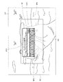
FIG. 6 is an explanatory diagram illustrating an example of the control image CI before the size is adjusted. FIG. 6 shows a visual field VR visually recognized by the user when the control image CI is displayed on the
画像表示部20が制御用画像CIを表示する場合、初めに、画像判定部142は、パターンマッチングにより検出した使用者の手のひらHDにおいて、予め設定された親指の先端SP1、人差し指の先端SP2、小指の先端SP3、の位置を検出する。画像表示部20は、親指の先端SP1、人差し指の先端SP2、小指の先端SP3の内、少なくとも1つの先端を頂点とし、かつ、残り2つの先端を通り、最大画像表示領域PNの横軸および縦軸と平行な線を外枠とする矩形状の制御用画像CIを表示する。図6では、小指の先端SP3を頂点として、親指の先端SP1および人差し指の先端SP2を通る矩形状の制御用画像CIが示されている。画像判定部142は、生成された制御用画像CIの外枠の縦および横の辺の長さのそれぞれが所定の長さ以上であるか否かを判定することで、制御用画像CIが所定の大きさ以上であるか否かを判定する。図6では、大きさを調整する前の制御用画像CIにおける縦の外枠が所定の長さ未満であるため、制御用画像CIが所定の大きさ以上ではないと判定され、画像表示部20は、制御用画像CIの大きさを調整して表示する。
When the
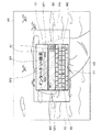
図7は、大きさが調整された後の制御用画像CIの一例を示す説明図である。図7には、画像表示部20が大きさを調整した制御用画像CIが表示され、使用者が視認する視野VRが示されている。図7に示すように、画像表示部20は、所定の長さ未満であると判定された縦の外枠を長くする調整を行なった制御用画像CIを表示する。図6では、大きさが調整される前の制御用画像CIが仮に表示された場合、制御用画像CIが最大画像表示領域PNにおける上の部分に生成されている。そのため、制御用画像CIの大きさが調整された後では、図7に示すように、画像表示部20は、制御用画像CIの縦の外枠を下に延長して表示する。本実施形態では、延長される外枠の縦の長さは、予め制御用画像CIが表示される場合に設定されている長さに対して足りない長さである。
FIG. 7 is an explanatory diagram illustrating an example of the control image CI whose size has been adjusted. In FIG. 7, the control image CI whose size is adjusted by the
図7に示すように、表示される制御用画像CIには、ポインターP1と、キーボードKBと、入力スペースIB1,IB2と、検索ボタンB1と、切替キーB2と、メニュー切替キーB3と、が含まれている。ポインターP1は、制御用画像CIにおける使用者の視線方向に対応する位置を表わす位置画像である。キーボードKBは、アルファベットが配置されているキーボードであり、キーボードKBとポインターP1とを用いて入力された文字が入力スペースIB1,IB2に表示される。キーボードKBは、アルファベットの大文字と小文字とを切り替える切替キーB2を含んでいる。検索ボタンB1は、入力スペースIB1,IB2に入力された文字に基づいてインターネットでの検索を実行するボタンである。メニュー切替キーB3は、制御用画像CIを、例えば、特定のフォルダーに保存されたファイルの一覧を表示するといった、異なる制御用画像へと切り替えるボタンである。なお、キーボードKBに含まれる各アルファベットに対応するキー、検索ボタンB1、切替キーB2、および、メニュー切替キーB3は、請求項におけるオブジェクトに相当する。 As shown in FIG. 7, the displayed control image CI includes a pointer P1, a keyboard KB, input spaces IB1 and IB2, a search button B1, a switching key B2, and a menu switching key B3. It is. The pointer P1 is a position image representing a position corresponding to the user's line-of-sight direction in the control image CI. The keyboard KB is a keyboard on which alphabets are arranged, and characters input using the keyboard KB and the pointer P1 are displayed in the input spaces IB1 and IB2. The keyboard KB includes a switching key B2 for switching between uppercase and lowercase letters of the alphabet. The search button B1 is a button for executing a search on the Internet based on the characters input in the input spaces IB1 and IB2. The menu switching key B3 is a button for switching the control image CI to a different control image, for example, displaying a list of files stored in a specific folder. The keys corresponding to the alphabets included in the keyboard KB, the search button B1, the switching key B2, and the menu switching key B3 correspond to objects in the claims.
制御用画像CIが表示されると(図4のステップ370)、次に、視線入力部175は、使用者の視線方向とまぶたの状態とに基づく入力の検出を監視する(図5のステップS380)。本実施形態では、画像判定部142が撮像される使用者の右眼の視線方向を判定し、画像表示部20は、右眼の視線方向に対応する位置にポインターP1を表示する。そのため、使用者の視線方向の変化に応じて、ポインターP1は、制御用画像CIにおける位置を変更する。視線入力部175は、予め定められた決定の操作を示すまぶたの状態が検出されない場合には(ステップS380:NO)、引き続き、決定の操作を示すまぶたの状態の検出を監視する(ステップS380)。
When the control image CI is displayed (step 370 in FIG. 4), the line-of-
ステップS380の処理において、ポインターP1が制御用画像CIの選択可能なボタンと重なっている状態で、決定の操作を示すまぶたの状態である左まぶたが所定の期間閉じた状態で右まぶたの瞬きが検出された場合には(ステップS380:YES)、視線入力部175は、入力の操作を行なう。視線入力部175は、ポインターP1が重なっているキーを決定して入力の操作を行ない、画像表示部20が入力結果を入力スペースIB1,IB2に表示する(ステップS390)。図7に示すように、入力スペースIB1,IB2には、アルファベットの大文字で、「A」、「B」、「C」が入力されて表示されている。本実施形態では、切替キーB2が決定された後に、「a」のアルファベットが決定されると、画像表示部20は、大文字の「A」を入力スペースIB1,IB2に表示する。そのため、図7における入力スペースIB1,IB2の入力結果は、切替キーB2、「a」、切替キーB2、「b」、切替キーB2、「c」のキーが順番に選択された状態である。なお、他の実施形態では、切替キーB2が決定されると、それ以降のアルファベットの大小が入れ替わって固定されてもよいし、キーボードKBの各キーに表示された小文字のアルファベットが大文字に変化して表示されてもよい。
In the process of step S380, with the pointer P1 overlapping the selectable button of the control image CI, the blinking of the right eyelid with the eyelid indicating the determination operation closed for a predetermined period If detected (step S380: YES), the line-of-
次に、眼撮像カメラ37,38は、入力スペースIB1,IB2への入力を終了してインターネット検索を行なう操作を示すまぶたの状態の検出を監視する(図4のステップS400)。インターネット検索を行なう操作を示すまぶたの状態が検出されない場合には(ステップS400:NO)、引き続き、決定の操作を示すまぶたの状態の検出を監視する(ステップS380)。インターネット検索を行なう操作を示す検索ボタンB1を決定するまぶたの状態が検出されると(ステップS400:YES)、制御部10が無線通信部132を介してインターネット検索を行ない、画像表示部20は、検索結果を表示する(ステップS410)。検索結果が表示されると、制御用画像CIが表示された場合と同じように、画像判定部142が判定した視線方向の変化に基づいてポインターP1が表示される位置が変更される。また、決定を示すまぶたの状態が検出されると、視線入力部175は、表示された検索結果における選択可能なアイコン等とポインターP1との位置に基づいて各種操作を行なう。
Next, the
次に、眼撮像カメラ37,38は、画像表示部20に表示された検索結果を異なる表示画像へと変更する操作を示すまぶたの状態の検出を監視する(ステップS420)。表示された検索結果を変更する操作として、所定の時間に右まぶたが閉じた状態で左まぶたが開いた状態が検出されると(ステップS420:YES)、眼撮像カメラ37,38が入力の検出を監視する(ステップS380)。表示された検索結果を変更するまぶたの状態が検出されない場合には(ステップS420:NO)、眼撮像カメラ37,38は、視線操作入力処理を終了する操作を示すまぶたの状態の検出を監視する(ステップS430)。視線操作入力処理を終了する操作を示すまぶたの状態が検出されない場合には(ステップS430:NO)、眼撮像カメラ37,38が入力の検出を監視する(ステップS380)。視線操作入力を終了する操作として、両まぶたを所定の時間閉じた後に右まぶたのみを所定の時間開いた状態が検出されると(ステップS430:YES)、制御部10は、視線操作入力処理を終了する。
Next, the
以上説明したように、本実施形態における頭部装着型表示装置100では、画像表示部20は、ポインターP1と、キーボードKBと、入力スペースIB1,IB2と、検索ボタンB1と、切替キーB2と、メニュー切替キーB3と、を含む制御用画像CIを表示する。視線入力部175は、キーボードKB等とポインターP1との位置関係に基づいて、頭部装着型表示装置100を制御する。そのため、本実施形態における頭部装着型表示装置100では、使用者の視線方向に基づいて、使用者が手を使わなくても頭部装着型表示装置100の各種制御を行なうことができ、使用者の操作性が向上する。また、物体として形を持ったキーボード等のユーザーインターフェースがなくても、使用者が頭部装着型表示装置100の制御を行なうことができ、頭部装着型表示装置100の携帯性が向上する。
As described above, in the head-mounted
また、本実施形態における頭部装着型表示装置100では、眼撮像カメラ37,38が使用者の右眼および左眼のそれぞれを撮像し、画像判定部142が両まぶたの開閉状態を判定する。視線入力部175は、キーボードKBとポインターP1の位置関係に基づいてキーボードKBにおけるアルファベットのキーを選択し、両まぶたの開閉状態に基づいて選択したキーの決定を行なう。そのため、本実施形態における頭部装着型表示装置100では、使用者の視線方向と両まぶたの開閉状態に基づいて頭部装着型表示装置100が制御されるため、使用者は全く手を使わずに頭部装着型表示装置100を制御でき、使用者の操作性が向上する。また、両まぶたの開閉状態の組み合わせに基づいて、決定が行なわれるため、操作の種類に対応した多くの決定の組み合わせを使用者に提供でき、使用者の操作性が向上する。
In the head-mounted
また、本実施形態における頭部装着型表示装置100では、画像判定部142は、距離センサー63が検出した対象物に対して、予め登録された設定対象物と同じであるかのパターンマッチングを行なう。画像判定部142のパターンマッチングによって、特定の対象物が予め設定された設定対象物である場合に、画像表示部20は、撮像された特定の対象物の大きさに応じて設定した制御用画像CIを表示する。そのため、本実施形態の頭部装着型表示装置100では、画像判定部142が認識した対象物の大きさに応じて制御用画像CIの大きさを変更するため、使用者は、感覚的に制御用画像CIの大きさを調整することができ、使用者の利便性が向上する。また、制御用画像CIが非表示の状態から表示の状態へと変化させるために、使用者は、単に手のひらHDを目の前にかざすだけでよいので、使用者の利便性が向上する。
In the head-mounted
B.変形例:
なお、この発明は上記実施形態に限られるものではなく、その要旨を逸脱しない範囲において種々の態様において実施することが可能であり、例えば、次のような変形も可能である。
B. Variations:
In addition, this invention is not limited to the said embodiment, It can implement in a various aspect in the range which does not deviate from the summary, For example, the following deformation | transformation is also possible.
B1.変形例1:
図8は、画像表示部20に表示される制御用画像CIaの一例を示す説明図である。図8には、使用者が視認する外景SCおよび表示された制御用画像CIaを含む視野VRが示されている。制御用画像CIaは、無線通信部132を介して頭部装着型表示装置100に接続されたテレビの操作部(リモコン)を表わす画像である。制御用画像CIaには、テレビの電源のON/OFFを切り替える電源ボタンPWと、テレビの音量を調節する音量ボタンVup,Vdwと、テレビのチャンネルを変更するチャンネル変更ボタンCup,Cdwと、が含まれている。音量ボタンVupが選択されて決定されると、テレビの音量が所定の数値だけ大きくなり、音量ボタンVdwが選択されて決定されると、テレビの音量が所定の数値だけ小さくなる。チャンネル変更ボタンCupが選択されて決定されると、テレビは、受信してチャンネル数を所定の数だけ大きいチャンネル数に設定して受信する。チャンネル変更ボタンCdwが選択されて決定されると、テレビは、受信してチャンネル数を所定の数だけ小さいチャンネル数に設定して受信する。また、制御用画像CIaには、テレビと有線で接続されているDVD再生機の操作を行なう複数のボタンを有するDVD操作ボタン群PBも含まれている。図8に示すように、ポインターP1は、DVD操作ボタン群PBに含まれるDVD再生機の再生を停止する停止ボタンSBに重なる位置に表示されている。上記実施形態と同じように、眼撮像カメラ37,38が決定の操作を示すまぶたの状態を検出すると、視線入力部175は、DVD再生機で再生されているコンテンツを停止させる。この変形例では、頭部装着型表示装置100と接続している装置の調整が、使用者の視線方向およびまぶたの状態によって操作される。
B1. Modification 1:
FIG. 8 is an explanatory diagram illustrating an example of the control image CIa displayed on the
図9は、画像表示部20に表示される制御用画像CIbの一例を示す説明図である。図9には、使用者が視認する外景SCおよび表示された制御用画像CIbを含む視野VRが示されている。図8に示す制御用画像CIbは、記憶部120に記憶されている動画や音楽といったコンテンツに関連付けられた文字で表わされた複数のアイコン画像を一覧として表示する画像である。制御用画像CIbは、カーソル画像C1と、一覧画像C2と、ポインターP1と、から構成されている。この変形例では、カーソル画像C1は、十字の形をしており、上下左右の方向のそれぞれが選択される画像である。図8に示すように、ポインターP1が十字の右方向を指す矢印の部分に重なった状態で、決定の操作を示すまぶたの状態が検出されると、一覧画像C2において、地図のアイコン画像を選択していることを表示している選択表示画像SIが1つ右に移動する。この変形例では、一覧画像C2において、地図のアイコン画像の右に他のアイコン画像がないため、選択表示画像SIは、ループして左のメールのアイコン画像に移動して、メールのアイコン画像に重なって表示される。また、この変形例では、カーソル画像C1の十字方向のいずれかにポインターP1を重ねた状態で決定の操作が行なわれなくても、ポインターP1を一覧画像C2のいずれかのアイコン画像に重ねた状態で特定のアイコン画像を選択して決定することもできる。特定のアイコン画像が選択表示画像SIと重なって表示されている状態で、ポインターP1が決定キーRBに重なった状態で決定の操作が行なわれると、選択表示画像SIと重なって表示されているアイコン画像が決定されて、当該アイコン画像に関連付けられた操作が行なわれる。
FIG. 9 is an explanatory diagram illustrating an example of the control image CIb displayed on the
B2.変形例2:
また、上記実施形態では、まぶたの開閉状態に基づいて決定の操作が検出されたが、決定の操作を検出する方法はまぶたの開閉状態に限られず、種々変形可能である。まぶたが開いている状態であっても、使用者が視認する外景の色や照度に基づいて各種操作が行なわれてもよい。この変形例では、照度センサー45,47が使用者の右眼および左眼に視認されると想定される外景の照度を検出する。そのため、使用者がまぶたを閉じなくても、例えば、使用者の手のひらによって左光学像表示部28の表面が覆われると、左眼に外景画視認されなくなるため、左眼照度センサー47は、右眼照度センサー45が検出する照度よりも小さい値の照度を検出する。照度処理部145が左眼照度センサー47によって検出する照度が右眼照度センサー45によって検出する照度よりも所定の閾値以上小さいと判定した場合に、視線入力部175は、上記実施形態における左のまぶたが閉じられた状態と同様の操作を行なう。そのため、この変形例の頭部装着型表示装置100では、使用者は、まぶたの状態による操作に疲れた場合に、手のひら等の体の一部を用いて感覚的に操作を行なうことができ、使用者の利便性が向上する。
B2. Modification 2:
In the above embodiment, the determination operation is detected based on the open / closed state of the eyelid. However, the method for detecting the determination operation is not limited to the open / closed state of the eyelid, and various modifications are possible. Even when the eyelids are open, various operations may be performed based on the color and illuminance of the outside scene visually recognized by the user. In this modification, the
また、他の変形例では、照度センサー45,47の代わりに、右眼および左眼のそれぞれの視線方向のRGBデータを検出するRGBカラーセンサーが配置されてもよい。右眼および左眼のそれぞれに対応したRGBカラーセンサーが検出した値によって、各種操作が行なわれてもよい。例えば、左光学像表示部28の表面が覆われた場合に、左眼に対応するRGBカラーセンサーは、黒に近い色を表わすRGBデータとなる。逆に、右眼に対応するRGBカラーセンサーが検出したRGBデータが黒に近い色を表わさない場合に、使用者の左まぶたが閉じられている状態と判定されてもよい。
In another modification, instead of the
B3.変形例3:
また、上記実施形態では、制御用画像CIが予め定められた位置に表示されるとしたが、制御用画像CIが表示される位置は予め定められた位置等に固定される必要はなく、制御用画像CIの表示位置および表示位置の変更方法については、種々変形可能である。この変形例の頭部装着型表示装置100では、9軸センサー66および方向判定部161が使用者の頭部の向きを推定して、推定した頭部の向きと重力方向とがなす角度を算出する。例えば、使用者が上を向いて、方向判定部161が算出した角度が所定の角度以上である場合には、画像表示部20は、制御用画像CIを最大画像表示領域PNにおける上の部分以外に表示する。そのため、この変形例の頭部装着型表示装置100では、使用者が頭部の向きを変更して、使用者が視認したい対象が変更されたことが推定され、使用者の視界を妨げない位置に自動的に制御用画像CIが表示されるため、使用者の利便性が向上する。
B3. Modification 3:
In the above embodiment, the control image CI is displayed at a predetermined position. However, the position at which the control image CI is displayed does not need to be fixed at a predetermined position or the like. The display position of the image CI and the method for changing the display position can be variously modified. In the head-mounted
また、画像表示部20が制御用画像CIを表示する位置が使用者の視線方向やまぶたの開閉状態等に基づいて変更されてもよい。例えば、眼撮像カメラ37,38が使用者の右まぶただけが所定の時間閉じた状態を検出した後、ある一定の期間内に、左まぶただけが所定の時間閉じた状態を検出すると、使用者の視線方向に基づいて制御用画像CIが最大画像表示領域PNにおける位置が変更されてもよい。この変形例の頭部装着型表示装置100では、使用者の意思に基づいて制御用画像CIを表示させる位置を、手などを使わずに設定できるため、使用者の操作性および利便性が向上する。
Further, the position where the
また、上記実施形態では、設定対象物としての手のひらHDが検出されると、撮像された手のひらHDの大きさに応じて制御用画像CIが表示されたが、設定対象物と制御用画像CIとの関係についてはこれに限られず、種々変形可能である。例えば、撮像された手のひらHDの大きさや形に応じて、表示される制御用画像CIの種類が変更されてもよい。また、撮像された手のひらHDと画像表示部20との位置関係に基づいて、制御用画像CIの表示位置が最大画像表示領域PNの中心以外に設定されてもよい。この変形例では、撮像された設定対象物の位置や大きさに基づいて、透過する外景SCと制御用画像CIとが多くの領域で重複しないように使用者に視認させることができ、使用者の利便性が向上する。
Further, in the above embodiment, when the palm HD as the setting object is detected, the control image CI is displayed according to the size of the captured palm HD, but the setting object and the control image CI are displayed. The relationship is not limited to this and can be variously modified. For example, the type of the control image CI to be displayed may be changed according to the size and shape of the captured palm HD. Further, based on the positional relationship between the captured palm HD and the
B4.変形例4:
また、上記実施形態では、距離センサー63によって、距離センサー63から所定の距離内にある対象物を検出したが、頭部装着型表示装置100が必ずしも距離センサー63を備える必要はなく、頭部装着型表示装置100の構成については種々変形可能である。例えば、外景撮像カメラ61および画像判定部142が、対象物との距離とは関係なく、撮像した対象物に対してパターンマッチングを行なって設定対象物であるか否かを判定してもよい。
B4. Modification 4:
In the above embodiment, the
また、上記実施形態では、眼撮像カメラ37,38および画像判定部142によってまぶたの開閉状態が判定されたが、使用者の視線方向を遮る遮蔽物を検出する方法はこれに限られず、種々変形可能である。例えば、眼撮像カメラ37,38の代わりに、赤外線センサーを用いてもよい。赤外線センサーは、発光した赤外線が使用者の眼またはまぶたに反射し、反射した反射光に基づいて、使用者のまぶたの開閉状態を判定する。また、画像判定部142は、パターンマッチングではなく、眼撮像カメラ37,38が取得した画像のRGBデータを黒と白とに2値化し、2値化したデータに基づいて使用者のまぶたの開閉状態を判定してもよい。
In the above-described embodiment, the open / closed state of the eyelid is determined by the
また、眼撮像カメラ37,38には、スタビライザー機能は備え付けられていてもよい。スタビライザー機能によって、眼撮像カメラ37,38は、例えば、使用者が歩行中の場合に、歩行によって生じるぶれを軽減するため、まぶたの状態をより正確に検出して判定できる。
The
また、操作部135と検出されたまぶたの状態とに基づいて、電源130の電力消費が抑制される態様であってもよい。例えば、操作部135におけるトラックパッド14が使用者からの操作を受け付けている場合には、使用者のまぶたの状態を検出する眼撮像カメラ37,38および照度センサー45,47への電力供給を停止してもよい。また、使用者の視線方向およびまぶたの状態によって頭部装着型表示装置100および頭部装着型表示装置100に接続された装置が操作されている場合には、操作部135への電力供給を停止してもよい。この変形例では、操作部135と制御用画像CIとの内の一方の操作部によって使用者からの操作を受け付けている場合に、操作を受け付けていない操作部への電力を停止することで、頭部装着型表示装置100が消費する電力を抑制できる。また、制御部10の代わりに、例えば、スマートフォンのような携帯端末と接続されて、接続された携帯端末の電力消費を抑制してもよい。
Further, the power consumption of the
また、上記実施形態では、視線入力部175が使用者の視線方向およびまぶたの状態に基づいて頭部装着型表示装置100の操作を行なったが、必ずしも頭部装着型表示装置100を操作する方法はこれに限られず、種々変形可能である。例えば、眼撮像カメラ37,38および画像判定部142は使用者の視線方向のみを検出して、視線方向に基づいて制御用画像CIに含まれるいずれかのキーが選択されて、操作部135に含まれるいずれかのボタンで決定されてもよい。また、操作部135に含まれるボタンではなく、別途、別に備えられたユーザーインターフェースであってもよいし、画像表示部20に形成された決定ボタン等であってもよい。この変形例では、単に視線方向のみで選択を行ない、決定がまぶたの状態ではなく、操作部135に備え付けられたボタン等で行なわれるため、使用者が簡単に決定の操作を行なうことができ、使用者の利便性および操作性が向上する。
In the above embodiment, the line-of-
また、上記実施形態では、請求項におけるオブジェクトに相当する具体例として、キーボードKBに含まれる各アルファベットに対応するキー、検索ボタンB1、切替キーB2、および、メニュー切替キーB3と、請求項におけるポインターに相当する具体例として、ポインターP1を例に挙げて説明したが、オブジェクトおよびポインターについては、種々変形可能である。例えば、請求項におけるオブジェクトまたはポインターとして、目印、標識、マーカー、記号、選択ボタン、ソフトキー、および、ソフトキーボードといったように、形状、色、および、図形等が変形された態様であってもよい。 In the above embodiment, as specific examples corresponding to the objects in the claims, keys corresponding to the alphabets included in the keyboard KB, search buttons B1, switching keys B2, and menu switching keys B3, and pointers in the claims As a specific example corresponding to, the pointer P1 has been described as an example, but the object and the pointer can be variously modified. For example, as an object or a pointer in the claims, a shape, a color, a figure, or the like may be modified such as a mark, a sign, a marker, a symbol, a selection button, a soft key, and a soft keyboard. .
また、上記実施形態では、眼撮像カメラ37,38は、眼撮像カメラ37,38から所定の距離にあり、視線方向上にあるまぶたの開閉を検出したが、必ずしも、所定の距離にあるまぶた等の遮蔽物を検出しなくてもよい。例えば、所定の距離までの一定の範囲内に存在する遮蔽物を検出することで、まぶたの開閉を検出したことと同様の操作が行なわれてもよい。
In the above-described embodiment, the
B5.変形例5:
また、外景撮像カメラ61は、制御部10に配置されてもよいし、制御部10や画像表示部20とは別体で、例えば、使用者が装着するヘルメットの上部等に配置されてもよい。
B5. Modification 5:
The outside
また、上記実施形態では、図2に示すように、9軸センサー66、距離センサー63、外景撮像カメラ61、眼撮像カメラ37,38、および、照度センサー45,47は、画像表示部20に配置されたが、必ずしも画像表示部20に配置される必要はなく、配置については種々変形可能である。例えば、右眼撮像カメラ37,38は、画像表示部20とは別体になっており、画像表示部20とは別に頭部に装着される態様であってもよいし、画像表示部20に着脱可能に形成されてもよい。
In the above embodiment, as shown in FIG. 2, the 9-
上記実施形態では、制御部10に操作部135を形成したが、操作部135の態様については種々変形可能である。例えば、制御部10とは別体で操作部135であるユーザーインターフェースがある態様でもよい。この場合に、操作部135は、電源130等が形成された制御部10とは別体であるため、小型化でき、使用者の操作性が向上する。また、操作部135の動きを検出する9軸センサーを操作部135に形成して、検出した動きに基づいて各種操作が行なわれることで、使用者は、感覚的に頭部装着型表示装置100の操作ができる。
In the above embodiment, the
例えば、画像光生成部は、有機EL(有機エレクトロルミネッセンス、Organic Electro-Luminescence)のディスプレイと、有機EL制御部とを備える構成としてもよい。また、例えば、画像生成部は、LCDに代えて、LCOS(Liquid crystal on silicon, LCoS は登録商標)や、デジタル・マイクロミラー・デバイス等を用いることもできる。また、例えば、レーザー網膜投影型のヘッドマウントディスプレイに対して本発明を適用することも可能である。レーザー網膜投影型の場合、「画像光生成部における画像光の射出可能領域」とは、使用者の眼に認識される画像領域として定義することができる。 For example, the image light generation unit may include an organic EL (Organic Electro-Luminescence) display and an organic EL control unit. Further, for example, the image generation unit may use LCOS (Liquid crystal on silicon, LCoS is a registered trademark), a digital micromirror device, or the like instead of the LCD. Further, for example, the present invention can be applied to a laser retinal projection type head mounted display. In the case of the laser retinal projection type, the “image light emitting area in the image light generation unit” can be defined as an image area recognized by the user's eyes.
また、例えば、ヘッドマウントディスプレイは、光学像表示部が使用者の眼の一部分のみを覆う態様、換言すれば、光学像表示部が使用者の眼を完全に覆わない態様のヘッドマウントディスプレイとしてもよい。また、ヘッドマウントディスプレイは、いわゆる単眼タイプのヘッドマウントディスプレイであるとしてもよい。 Further, for example, the head-mounted display may be a head-mounted display in which the optical image display unit covers only a part of the user's eye, in other words, the optical image display unit does not completely cover the user's eye. Good. The head mounted display may be a so-called monocular type head mounted display.
また、イヤホンは耳掛け型やヘッドバンド型を採用してもよく、省略してもよい。また、例えば、自動車や飛行機等の車両に搭載されるヘッドマウントディスプレイとして構成されてもよい。また、例えば、ヘルメット等の身体防護具に内蔵されたヘッドマウントディスプレイとして構成されてもよい。 The earphone may be an ear-hook type or a headband type, or may be omitted. Further, for example, it may be configured as a head mounted display mounted on a vehicle such as an automobile or an airplane. Further, for example, it may be configured as a head-mounted display built in a body protective device such as a helmet.
B6.変形例6:
上記実施形態における頭部装着型表示装置100の構成は、あくまで一例であり、種々変形可能である。例えば、制御部10に設けられた方向キー16やトラックパッド14の一方を省略したり、方向キー16やトラックパッド14に加えてまたは方向キー16やトラックパッド14に代えて操作用スティック等の他の操作用インターフェイスを設けたりしてもよい。また、制御部10は、キーボードやマウス等の入力デバイスを接続可能な構成であり、キーボードやマウスから入力を受け付けるものとしてもよい。
B6. Modification 6:
The configuration of the head-mounted
また、画像表示部として、眼鏡のように装着する画像表示部20に代えて、例えば帽子のように装着する画像表示部といった他の方式の画像表示部を採用してもよい。また、イヤホン32,34、外景撮像カメラ61、は適宜省略可能である。また、上記実施形態では、画像光を生成する構成として、LCDと光源とを利用しているが、これらに代えて、有機ELディスプレイといった他の表示素子を採用してもよい。また、上記実施形態では、使用者の頭の動きを検出するセンサーとして9軸センサー66を利用しているが、これに代えて、加速度センサー、角速度センサー、地磁気センサーのうちの1つまたは2つから構成されたセンサーを利用するとしてもよい。また、上記実施形態では、頭部装着型表示装置100は、両眼タイプの光学透過型であるとしているが、本発明は、例えばビデオ透過型や単眼タイプといった他の形式の頭部装着型表示装置にも同様に適用可能である。
As the image display unit, instead of the
また、上記実施形態において、頭部装着型表示装置100は、使用者の左右の眼に同じ画像を表わす画像光を導いて使用者に二次元画像を視認させるとしてもよいし、使用者の左右の眼に異なる画像を表わす画像光を導いて使用者に三次元画像を視認させるとしてもよい。
In the above-described embodiment, the head-mounted
また、上記実施形態において、ハードウェアによって実現されていた構成の一部をソフトウェアに置き換えるようにしてもよく、逆に、ソフトウェアによって実現されていた構成の一部をハードウェアに置き換えるようにしてもよい。例えば、上記実施形態では、画像処理部160や音声処理部170は、CPU140がコンピュータープログラムを読み出して実行することにより実現されるとしているが、これらの機能部はハードウェア回路により実現されるとしてもよい。
In the above embodiment, a part of the configuration realized by hardware may be replaced by software, and conversely, a part of the configuration realized by software may be replaced by hardware. Good. For example, in the above-described embodiment, the
また、本発明の機能の一部または全部がソフトウェアで実現される場合には、そのソフトウェア(コンピュータープログラム)は、コンピューター読み取り可能な記録媒体に格納された形で提供することができる。この発明において、「コンピューター読み取り可能な記録媒体」とは、フレキシブルディスクやCD−ROMのような携帯型の記録媒体に限らず、各種のRAMやROM等のコンピューター内の内部記憶装置や、ハードディスク等のコンピューターに固定されている外部記憶装置も含んでいる。 In addition, when part or all of the functions of the present invention are realized by software, the software (computer program) can be provided in a form stored in a computer-readable recording medium. In the present invention, the “computer-readable recording medium” is not limited to a portable recording medium such as a flexible disk or a CD-ROM, but an internal storage device in a computer such as various RAMs and ROMs, a hard disk, etc. It also includes an external storage device fixed to the computer.
また、上記実施形態では、図1および図2に示すように、制御部10と画像表示部20とが別々の構成として形成されているが、制御部10と画像表示部20との構成については、これに限られず、種々変形可能である。例えば、画像表示部20の内部に、制御部10に形成された構成の全てが形成されてもよいし、一部が形成されてもよい。また、上記実施形態における電源130が単独で形成されて、交換可能な構成であってもよいし、制御部10に形成された構成が重複して画像表示部20に形成されていてもよい。例えば、図2に示すCPU140が制御部10と画像表示部20との両方に形成されていてもよいし、制御部10に形成されたCPU140と画像表示部20に形成されたCPUとが行なう機能が別々に分けられている構成としてもよい。
Moreover, in the said embodiment, as shown in FIG. 1 and FIG. 2, the
また、制御部10がパーソナルコンピューター(PC)に内蔵されて、PCのモニターに代えて画像表示部20が使用される態様であってもよいし、制御部10と画像表示部20とが一体化して、使用者の衣服に取り付けられるウェアラブルコンピューターの態様であってもよい。
Further, the
本発明は、上記実施形態や変形例に限られるものではなく、その趣旨を逸脱しない範囲において種々の構成で実現することができる。例えば、発明の概要の欄に記載した各形態中の技術的特徴に対応する実施形態、変形例中の技術的特徴は、上述の課題の一部または全部を解決するために、あるいは、上述の効果の一部または全部を達成するために、適宜、差し替えや、組み合わせを行なうことが可能である。また、その技術的特徴が本明細書中に必須なものとして説明されていなければ、適宜、削除することが可能である。 The present invention is not limited to the above-described embodiments and modifications, and can be realized with various configurations without departing from the spirit of the present invention. For example, the technical features in the embodiments and the modifications corresponding to the technical features in each form described in the summary section of the invention are to solve some or all of the above-described problems, or In order to achieve part or all of the effects, replacement or combination can be performed as appropriate. Further, if the technical feature is not described as essential in the present specification, it can be deleted as appropriate.
10…制御部
11…決定キー
12…点灯部
13…表示切替キー
14…トラックパッド
15…輝度切替キー
16…方向キー
17…メニューキー
18…電源スイッチ
20…画像表示部
21…右保持部
22…右表示駆動部
23…左保持部
24…左表示駆動部
26…右光学像表示部
28…左光学像表示部
30…イヤホンプラグ
32…右イヤホン
34…左イヤホン
37…右眼撮像カメラ(検出部、視線方向検出部)
38…左眼撮像カメラ(検出部、視線方向検出部)
40…接続部
42…右コード
44…左コード
45…右眼照度センサー(検出部)
46…連結部材
47…左眼照度センサー(検出部)
48…本体コード
51,52…送信部
53,54…受信部
61…外景撮像カメラ
63…距離センサー(画像認識部)
66…9軸センサー(向き検出部)
100…頭部装着型表示装置
110…入力情報取得部
120…記憶部
130…電源
132…無線通信部
135…操作部
140…CPU
142…画像判定部(視線方向検出部、画像認識部)
145…照度処理部(検出部)
150…オペレーティングシステム
160…画像処理部
161…方向判定部(向き検出部)
170…音声処理部
175…視線入力部(視線入力制御部)
180…インターフェイス
190…表示制御部
201…右バックライト制御部
202…左バックライト制御部
211…右LCD制御部
212…左LCD制御部
221…右バックライト
222…左バックライト
241…右LCD
242…左LCD
251…右投写光学系
252…左投写光学系
261…右導光板
262…左導光板
VSync…垂直同期信号
HSync…水平同期信号
PCLK…クロック信号
Data…画像データ
USBインターフェイス…マイクロ
P1…ポインター
B1…検索ボタン(オブジェクト)
B2…切替キー(オブジェクト)
B3…メニュー切替キー(オブジェクト)
C1…カーソル画像(制御用画像)
C2…一覧画像(制御用画像)
CI,CIa,CIb…制御用画像(制御用画像)
KB…キーボード
RB…決定キー(オブジェクト)
PB…DVD操作ボタン群
SB…停止ボタン(オブジェクト)
SC…外景
HD…手のひら
RE…右眼
LE…左眼
SI…選択表示画像
EL…端部
IL…照明光
PL…画像光
PN…最大画像表示領域
VR…視野
PW…電源ボタン(オブジェクト)
IB1,IB2…入力スペース
SP1…親指の先端
SP2…人差し指の先端
SP3…小指の先端
Vup,Vdw…音量ボタン(オブジェクト)
Cup,Cdw…チャンネル変更ボタン(オブジェクト)
DESCRIPTION OF
38 ... Left-eye imaging camera (detection unit, gaze direction detection unit)
40 ...
46 ... Connecting
48 ...
66 ... 9-axis sensor (direction detection unit)
DESCRIPTION OF
142 ... Image determination unit (gaze direction detection unit, image recognition unit)
145 ... Illuminance processing unit (detection unit)
DESCRIPTION OF
170 ...
180 ... interface 190 ...
242 ... Left LCD
251 ... Right projection
B2 ... Switching key (object)
B3 ... Menu switching key (object)
C1 ... Cursor image (control image)
C2 ... List image (control image)
CI, CIa, CIb ... control image (control image)
KB ... keyboard RB ... decision key (object)
PB ... DVD operation button group SB ... Stop button (object)
SC ... Outside view HD ... Hand RE ... Right eye LE ... Left eye SI ... Selected display image EL ... End IL ... Illumination light PL ... Image light PN ... Maximum image display area VR ... Field of view PW ... Power button (object)
IB1, IB2 ... input space SP1 ... tip of thumb SP2 ... tip of index finger SP3 ... tip of little finger Vup, Vdw ... volume button (object)
Cup, Cdw ... Channel change button (object)
Claims (9)
使用者の視線方向を検出する視線方向検出部と、
使用者の頭部に装着された状態において、外景を透過させると共に、複数の選択可能なオブジェクトと、検出された前記視線方向に対応した位置を示すポインターと、を含む制御用画像を、画像を表示可能な領域の一部であって、前記使用者の視認方向に重なる領域に表示させる画像表示部と、
複数の前記オブジェクトのうち、前記ポインターとの位置関係により選択可能な状態とされたオブジェクトに応じた内容の制御を行なう制御部と、
を備える、頭部装着型表示装置。 A head-mounted display device,
A gaze direction detection unit that detects the gaze direction of the user;
A control image including a plurality of selectable objects and a pointer indicating a position corresponding to the detected line-of-sight direction while transmitting the outside scene while being mounted on the user's head is displayed as an image. An image display unit that is a part of the displayable area and that is displayed in an area that overlaps the viewing direction of the user;
A control unit that controls content according to an object that is in a selectable state by a positional relationship with the pointer among the plurality of objects;
A head-mounted display device comprising:
使用者の眼から所定の距離に存在し、前記視線方向上の遮蔽物を検出する検出部を備え、
前記制御部は、前記遮蔽物の検出結果に基づいて、前記選択可能な状態とされた前記オブジェクトの決定を行なう、頭部装着型表示装置。 The head-mounted display device according to claim 1, further comprising:
A detection unit that is present at a predetermined distance from the user's eyes and that detects a shield in the line-of-sight direction;
The control unit is a head-mounted display device that determines the object in the selectable state based on a detection result of the shielding object.
前記検出部は、前記遮蔽物としての使用者のまぶたの状態を検出し、
前記制御部は、検出された前記まぶたの状態と前記位置関係とに応じた内容の制御を行なう、頭部装着型表示装置。 The head-mounted display device according to claim 2,
The detection unit detects the state of the user's eyelid as the shield,
The control unit is a head-mounted display device that controls contents according to the detected state of the eyelid and the positional relationship.
前記検出部は、使用者の右まぶたの開閉状態と左まぶたの開閉状態とを検出し、
前記制御部は、前記位置関係と、検出された前記右まぶたの開閉状態と前記左まぶたの開閉状態との組み合わせと、に応じた内容の制御を行なう、頭部装着型表示装置。 The head-mounted display device according to claim 3,
The detection unit detects the open / closed state of the user's right eyelid and the open / closed state of the left eyelid,
The head-mounted display device that controls contents according to the positional relationship and a combination of the detected opening / closing state of the right eyelid and the opening / closing state of the left eyelid.
前記検出部は、使用者の右眼と左眼とのそれぞれから前記所定の距離までの範囲における色または照度の少なくとも一方を示す右眼前指標値と左眼前指標値とを検出し、
前記制御部は、前記位置関係と、検出された前記右眼前指標値と前記左眼前指標値と、に応じた内容の制御を行なう、頭部装着型表示装置。 The head-mounted display device according to any one of claims 2 to 4,
The detection unit detects a right-eye pre-index value and a left-eye pre-index value indicating at least one of color or illuminance in a range from each of a user's right eye and left eye to the predetermined distance,
The said control part is a head mounted display apparatus which controls the content according to the said positional relationship, the detected said right front index value, and the said left front index value.
前記画像表示部は、前記制御用画像を表示する前記領域を、検出された前記視線方向と前記遮蔽物の検出結果とに基づいて設定する、頭部装着型表示装置。 A head-mounted display device according to any one of claims 2 to 5,
The image display unit is a head-mounted display device that sets the region for displaying the control image based on the detected line-of-sight direction and the detection result of the shielding object.
前記複数のオブジェクトはキーボードを構成する各キーを表すオブジェクトであり、
前記制御部は、前記ポインターとの位置関係により選択可能な状態とされたオブジェクトに応じた内容の制御として、前記ポインターが重なったオブジェクトに割り当てられたキーに対応した文字の入力を行なう
頭部装着型表示装置。 The head-mounted display device according to claim 1,
The plurality of objects are objects representing keys constituting the keyboard,
The control unit inputs a character corresponding to a key assigned to the object on which the pointer overlaps as a control of contents according to an object that can be selected by a positional relationship with the pointer. Type display device.
使用者の頭部の向きを検出する向き検出部を備え、
前記画像表示部は、検出された前記頭部の向きに基づいて、前記使用者の視認方向を特定する、頭部装着型表示装置。 The head-mounted display device according to any one of claims 1 to 6, further comprising:
It has an orientation detection unit that detects the orientation of the user's head,
The image display unit is a head-mounted display device that specifies the viewing direction of the user based on the detected orientation of the head.
前記頭部装着型表示装置に設けられたセンサにより、使用者の視線方向を検出し、
前記頭部装着型表示装置が使用者の頭部に装着された状態において、複数の選択可能なオブジェクトと、検出された前記視線方向に対応した位置を示すポインターと、を含む制御用画像を、外景を透過させることが可能な画像表示部における表示可能領域の一部であって、前記使用者の視認方向に重なる領域に表示させ、
複数の前記オブジェクトのうち、前記ポインターとの位置関係により選択可能な状態とされたオブジェクトに応じた内容の制御を行なう
制御方法。 A method for controlling a head-mounted display device,
The direction of the user's line of sight is detected by a sensor provided in the head-mounted display device,
In a state in which the head-mounted display device is mounted on the user's head, a control image including a plurality of selectable objects and a pointer indicating a position corresponding to the detected line-of-sight direction, It is a part of the displayable area in the image display unit that can transmit the outside scene, and is displayed in an area that overlaps the viewing direction of the user,
A control method for performing control of contents according to an object that can be selected by a positional relationship with the pointer among the plurality of objects.
Priority Applications (5)
| Application Number | Priority Date | Filing Date | Title |
|---|---|---|---|
| JP2013061466A JP6303274B2 (en) | 2013-03-25 | 2013-03-25 | Head-mounted display device and method for controlling head-mounted display device |
| US14/212,225 US9335547B2 (en) | 2013-03-25 | 2014-03-14 | Head-mounted display device and method of controlling head-mounted display device |
| EP14161099.8A EP2784632A3 (en) | 2013-03-25 | 2014-03-21 | Head-mounted display device and method of controlling head-mounted display device |
| CN201410108223.XA CN104076512B (en) | 2013-03-25 | 2014-03-21 | The control method of head-mount type display unit and head-mount type display unit |
| US15/137,072 US9921646B2 (en) | 2013-03-25 | 2016-04-25 | Head-mounted display device and method of controlling head-mounted display device |
Applications Claiming Priority (1)
| Application Number | Priority Date | Filing Date | Title |
|---|---|---|---|
| JP2013061466A JP6303274B2 (en) | 2013-03-25 | 2013-03-25 | Head-mounted display device and method for controlling head-mounted display device |
Related Child Applications (1)
| Application Number | Title | Priority Date | Filing Date |
|---|---|---|---|
| JP2018038150A Division JP6669183B2 (en) | 2018-03-05 | 2018-03-05 | Head mounted display and control method of head mounted display |
Publications (3)
| Publication Number | Publication Date |
|---|---|
| JP2014187574A JP2014187574A (en) | 2014-10-02 |
| JP2014187574A5 JP2014187574A5 (en) | 2016-03-10 |
| JP6303274B2 true JP6303274B2 (en) | 2018-04-04 |
Family
ID=51834678
Family Applications (1)
| Application Number | Title | Priority Date | Filing Date |
|---|---|---|---|
| JP2013061466A Active JP6303274B2 (en) | 2013-03-25 | 2013-03-25 | Head-mounted display device and method for controlling head-mounted display device |
Country Status (1)
| Country | Link |
|---|---|
| JP (1) | JP6303274B2 (en) |
Families Citing this family (7)
| Publication number | Priority date | Publication date | Assignee | Title |
|---|---|---|---|---|
| KR101638095B1 (en) * | 2015-01-16 | 2016-07-20 | 한국과학기술원 | Method for providing user interface through head mount display by using gaze recognition and bio-signal, and device, and computer-readable recording media using the same |
| JP6404196B2 (en) | 2015-09-16 | 2018-10-10 | グリー株式会社 | Virtual image display program, virtual image display device, and virtual image display method |
| JP6700849B2 (en) * | 2016-02-24 | 2020-05-27 | 株式会社ミツトヨ | Measuring system |
| JP6779734B2 (en) * | 2016-09-30 | 2020-11-04 | トキコシステムソリューションズ株式会社 | Fuel supply system |
| KR102662708B1 (en) * | 2016-10-17 | 2024-05-03 | 엘지전자 주식회사 | Head mounted display device |
| JP6669183B2 (en) * | 2018-03-05 | 2020-03-18 | セイコーエプソン株式会社 | Head mounted display and control method of head mounted display |
| JP6659789B2 (en) * | 2018-09-10 | 2020-03-04 | グリー株式会社 | Virtual image display program, virtual image display device, and virtual image display method |
Family Cites Families (8)
| Publication number | Priority date | Publication date | Assignee | Title |
|---|---|---|---|---|
| JPH0749744A (en) * | 1993-08-04 | 1995-02-21 | Pioneer Electron Corp | Head mounting type display input device |
| JPH0764709A (en) * | 1993-08-26 | 1995-03-10 | Olympus Optical Co Ltd | Instruction processor |
| JPH09179062A (en) * | 1995-12-25 | 1997-07-11 | Canon Inc | Computer system |
| JP2002318652A (en) * | 2001-04-20 | 2002-10-31 | Foundation For Nara Institute Of Science & Technology | Virtual input device and its program |
| JP4927631B2 (en) * | 2006-06-27 | 2012-05-09 | パナソニック株式会社 | Display device, control method therefor, program, recording medium, and integrated circuit |
| JP5228305B2 (en) * | 2006-09-08 | 2013-07-03 | ソニー株式会社 | Display device and display method |
| JP2010145861A (en) * | 2008-12-19 | 2010-07-01 | Brother Ind Ltd | Head mount display |
| JP2010152443A (en) * | 2008-12-24 | 2010-07-08 | Brother Ind Ltd | Head mounted display |
-
2013
- 2013-03-25 JP JP2013061466A patent/JP6303274B2/en active Active
Also Published As
| Publication number | Publication date |
|---|---|
| JP2014187574A (en) | 2014-10-02 |
Similar Documents
| Publication | Publication Date | Title |
|---|---|---|
| US9921646B2 (en) | Head-mounted display device and method of controlling head-mounted display device | |
| JP6277673B2 (en) | Head-mounted display device and method for controlling head-mounted display device | |
| JP6237000B2 (en) | Head-mounted display device | |
| JP6217244B2 (en) | Image processing apparatus, head-mounted display apparatus having the same, image processing method, and computer program | |
| JP6303274B2 (en) | Head-mounted display device and method for controlling head-mounted display device | |
| JP6488786B2 (en) | Head-mounted display device, head-mounted display device control method, and computer program | |
| JP6094305B2 (en) | Head-mounted display device and method for controlling head-mounted display device | |
| JP6264871B2 (en) | Information processing apparatus and information processing apparatus control method | |
| JP6318596B2 (en) | Information processing apparatus and information processing apparatus control method | |
| JP6459380B2 (en) | Head-mounted display device, head-mounted display device control method, and computer program | |
| TW201510573A (en) | Head mounted display device and control method for head mounted display device | |
| JP6379572B2 (en) | Head-mounted display device and method for controlling head-mounted display device | |
| JP6600945B2 (en) | Head-mounted display device, head-mounted display device control method, and computer program | |
| JP2016004340A (en) | Information distribution system, head-mounted type display device, control method of head-mounted type display device and computer program | |
| JP6427942B2 (en) | Head-mounted display device, control system, and head-mounted display device control method | |
| JP2015115848A (en) | Head-mounted type display device and method for controlling head-mounted type display device | |
| JP2016024208A (en) | Display device, method for controlling display device, and program | |
| JP6135162B2 (en) | Head-mounted display device, head-mounted display device control method, and image display system | |
| JP2015087523A (en) | Head-mounted display device, method for controlling head-mounted display device, and image display system | |
| JP6451222B2 (en) | Head-mounted display device, head-mounted display device control method, and computer program | |
| JP6304415B2 (en) | Head-mounted display device and method for controlling head-mounted display device | |
| JP6669183B2 (en) | Head mounted display and control method of head mounted display | |
| JP6287399B2 (en) | Head-mounted display device and method for controlling head-mounted display device | |
| JP6375662B2 (en) | Head-mounted display device | |
| JP6217772B2 (en) | Head-mounted display device and method for controlling head-mounted display device |
Legal Events
| Date | Code | Title | Description |
|---|---|---|---|
| A521 | Written amendment |
Free format text: JAPANESE INTERMEDIATE CODE: A523 Effective date: 20160121 |
|
| A621 | Written request for application examination |
Free format text: JAPANESE INTERMEDIATE CODE: A621 Effective date: 20160121 |
|
| RD04 | Notification of resignation of power of attorney |
Free format text: JAPANESE INTERMEDIATE CODE: A7424 Effective date: 20160530 |
|
| A977 | Report on retrieval |
Free format text: JAPANESE INTERMEDIATE CODE: A971007 Effective date: 20161017 |
|
| A131 | Notification of reasons for refusal |
Free format text: JAPANESE INTERMEDIATE CODE: A131 Effective date: 20161025 |
|
| A521 | Written amendment |
Free format text: JAPANESE INTERMEDIATE CODE: A523 Effective date: 20161222 |
|
| A131 | Notification of reasons for refusal |
Free format text: JAPANESE INTERMEDIATE CODE: A131 Effective date: 20170606 |
|
| A521 | Written amendment |
Free format text: JAPANESE INTERMEDIATE CODE: A523 Effective date: 20170807 |
|
| TRDD | Decision of grant or rejection written | ||
| A01 | Written decision to grant a patent or to grant a registration (utility model) |
Free format text: JAPANESE INTERMEDIATE CODE: A01 Effective date: 20180206 |
|
| A61 | First payment of annual fees (during grant procedure) |
Free format text: JAPANESE INTERMEDIATE CODE: A61 Effective date: 20180219 |
|
| R150 | Certificate of patent or registration of utility model |
Ref document number: 6303274 Country of ref document: JP Free format text: JAPANESE INTERMEDIATE CODE: R150 |