JP6237000B2 - Head-mounted display device - Google Patents
Head-mounted display device Download PDFInfo
- Publication number
- JP6237000B2 JP6237000B2 JP2013177866A JP2013177866A JP6237000B2 JP 6237000 B2 JP6237000 B2 JP 6237000B2 JP 2013177866 A JP2013177866 A JP 2013177866A JP 2013177866 A JP2013177866 A JP 2013177866A JP 6237000 B2 JP6237000 B2 JP 6237000B2
- Authority
- JP
- Japan
- Prior art keywords
- user
- hand
- image
- unit
- virtual image
- Prior art date
- Legal status (The legal status is an assumption and is not a legal conclusion. Google has not performed a legal analysis and makes no representation as to the accuracy of the status listed.)
- Active
Links
- 238000012545 processing Methods 0.000 claims description 95
- 238000001514 detection method Methods 0.000 claims description 68
- 230000002093 peripheral effect Effects 0.000 claims description 59
- 230000003190 augmentative effect Effects 0.000 claims description 26
- 238000013459 approach Methods 0.000 claims description 15
- 230000008859 change Effects 0.000 claims description 14
- 238000003384 imaging method Methods 0.000 description 135
- 230000003287 optical effect Effects 0.000 description 55
- 238000000034 method Methods 0.000 description 50
- 230000008569 process Effects 0.000 description 36
- 238000003860 storage Methods 0.000 description 23
- 230000033001 locomotion Effects 0.000 description 19
- 238000010586 diagram Methods 0.000 description 18
- 238000004364 calculation method Methods 0.000 description 17
- 230000006870 function Effects 0.000 description 16
- 210000003811 finger Anatomy 0.000 description 14
- 210000003128 head Anatomy 0.000 description 14
- 230000000007 visual effect Effects 0.000 description 14
- 230000005540 biological transmission Effects 0.000 description 12
- 125000002066 L-histidyl group Chemical group [H]N1C([H])=NC(C([H])([H])[C@](C(=O)[*])([H])N([H])[H])=C1[H] 0.000 description 10
- 230000006399 behavior Effects 0.000 description 9
- 238000006243 chemical reaction Methods 0.000 description 8
- 230000004048 modification Effects 0.000 description 5
- 238000012986 modification Methods 0.000 description 5
- 230000008901 benefit Effects 0.000 description 4
- 230000006854 communication Effects 0.000 description 4
- 238000004891 communication Methods 0.000 description 4
- 238000004590 computer program Methods 0.000 description 4
- 210000004709 eyebrow Anatomy 0.000 description 4
- 239000011521 glass Substances 0.000 description 4
- 239000004973 liquid crystal related substance Substances 0.000 description 4
- 230000008054 signal transmission Effects 0.000 description 4
- 230000005236 sound signal Effects 0.000 description 4
- 230000000694 effects Effects 0.000 description 3
- 230000001133 acceleration Effects 0.000 description 2
- 210000000988 bone and bone Anatomy 0.000 description 2
- 239000003086 colorant Substances 0.000 description 2
- 238000012937 correction Methods 0.000 description 2
- 238000005401 electroluminescence Methods 0.000 description 2
- 230000006698 induction Effects 0.000 description 2
- 239000011159 matrix material Substances 0.000 description 2
- 230000035807 sensation Effects 0.000 description 2
- 230000002123 temporal effect Effects 0.000 description 2
- 210000003813 thumb Anatomy 0.000 description 2
- 238000002834 transmittance Methods 0.000 description 2
- 241000282472 Canis lupus familiaris Species 0.000 description 1
- 241000282326 Felis catus Species 0.000 description 1
- 230000007175 bidirectional communication Effects 0.000 description 1
- 230000000295 complement effect Effects 0.000 description 1
- 239000000470 constituent Substances 0.000 description 1
- 210000000959 ear middle Anatomy 0.000 description 1
- 238000005516 engineering process Methods 0.000 description 1
- 239000000446 fuel Substances 0.000 description 1
- 210000004247 hand Anatomy 0.000 description 1
- 230000004886 head movement Effects 0.000 description 1
- 238000005286 illumination Methods 0.000 description 1
- 230000001771 impaired effect Effects 0.000 description 1
- 230000006872 improvement Effects 0.000 description 1
- 238000004519 manufacturing process Methods 0.000 description 1
- 239000000463 material Substances 0.000 description 1
- 239000002184 metal Substances 0.000 description 1
- 229910044991 metal oxide Inorganic materials 0.000 description 1
- 150000004706 metal oxides Chemical class 0.000 description 1
- 239000013307 optical fiber Substances 0.000 description 1
- 238000005192 partition Methods 0.000 description 1
- 238000003825 pressing Methods 0.000 description 1
- 230000001681 protective effect Effects 0.000 description 1
- 230000009467 reduction Effects 0.000 description 1
- 238000001028 reflection method Methods 0.000 description 1
- 239000011347 resin Substances 0.000 description 1
- 229920005989 resin Polymers 0.000 description 1
- 230000004044 response Effects 0.000 description 1
- 210000001525 retina Anatomy 0.000 description 1
- 230000004270 retinal projection Effects 0.000 description 1
- 239000004065 semiconductor Substances 0.000 description 1
- 230000007704 transition Effects 0.000 description 1
- 230000001960 triggered effect Effects 0.000 description 1
Images


Classifications
-
- G—PHYSICS
- G06—COMPUTING; CALCULATING OR COUNTING
- G06F—ELECTRIC DIGITAL DATA PROCESSING
- G06F3/00—Input arrangements for transferring data to be processed into a form capable of being handled by the computer; Output arrangements for transferring data from processing unit to output unit, e.g. interface arrangements
- G06F3/01—Input arrangements or combined input and output arrangements for interaction between user and computer
- G06F3/011—Arrangements for interaction with the human body, e.g. for user immersion in virtual reality
-
- G—PHYSICS
- G02—OPTICS
- G02B—OPTICAL ELEMENTS, SYSTEMS OR APPARATUS
- G02B27/00—Optical systems or apparatus not provided for by any of the groups G02B1/00 - G02B26/00, G02B30/00
- G02B27/01—Head-up displays
- G02B27/017—Head mounted
-
- G—PHYSICS
- G02—OPTICS
- G02B—OPTICAL ELEMENTS, SYSTEMS OR APPARATUS
- G02B27/00—Optical systems or apparatus not provided for by any of the groups G02B1/00 - G02B26/00, G02B30/00
- G02B27/01—Head-up displays
- G02B27/017—Head mounted
- G02B27/0172—Head mounted characterised by optical features
-
- G—PHYSICS
- G06—COMPUTING; CALCULATING OR COUNTING
- G06F—ELECTRIC DIGITAL DATA PROCESSING
- G06F3/00—Input arrangements for transferring data to be processed into a form capable of being handled by the computer; Output arrangements for transferring data from processing unit to output unit, e.g. interface arrangements
- G06F3/01—Input arrangements or combined input and output arrangements for interaction between user and computer
- G06F3/017—Gesture based interaction, e.g. based on a set of recognized hand gestures
-
- G—PHYSICS
- G06—COMPUTING; CALCULATING OR COUNTING
- G06F—ELECTRIC DIGITAL DATA PROCESSING
- G06F3/00—Input arrangements for transferring data to be processed into a form capable of being handled by the computer; Output arrangements for transferring data from processing unit to output unit, e.g. interface arrangements
- G06F3/16—Sound input; Sound output
- G06F3/167—Audio in a user interface, e.g. using voice commands for navigating, audio feedback
-
- G—PHYSICS
- G06—COMPUTING; CALCULATING OR COUNTING
- G06T—IMAGE DATA PROCESSING OR GENERATION, IN GENERAL
- G06T19/00—Manipulating 3D models or images for computer graphics
- G06T19/006—Mixed reality
-
- G—PHYSICS
- G02—OPTICS
- G02B—OPTICAL ELEMENTS, SYSTEMS OR APPARATUS
- G02B27/00—Optical systems or apparatus not provided for by any of the groups G02B1/00 - G02B26/00, G02B30/00
- G02B27/01—Head-up displays
- G02B27/0101—Head-up displays characterised by optical features
- G02B2027/0138—Head-up displays characterised by optical features comprising image capture systems, e.g. camera
-
- G—PHYSICS
- G02—OPTICS
- G02B—OPTICAL ELEMENTS, SYSTEMS OR APPARATUS
- G02B27/00—Optical systems or apparatus not provided for by any of the groups G02B1/00 - G02B26/00, G02B30/00
- G02B27/01—Head-up displays
- G02B27/0101—Head-up displays characterised by optical features
- G02B2027/014—Head-up displays characterised by optical features comprising information/image processing systems
-
- G—PHYSICS
- G02—OPTICS
- G02B—OPTICAL ELEMENTS, SYSTEMS OR APPARATUS
- G02B27/00—Optical systems or apparatus not provided for by any of the groups G02B1/00 - G02B26/00, G02B30/00
- G02B27/01—Head-up displays
- G02B27/017—Head mounted
- G02B2027/0178—Eyeglass type
-
- G—PHYSICS
- G02—OPTICS
- G02B—OPTICAL ELEMENTS, SYSTEMS OR APPARATUS
- G02B27/00—Optical systems or apparatus not provided for by any of the groups G02B1/00 - G02B26/00, G02B30/00
- G02B27/01—Head-up displays
- G02B27/0179—Display position adjusting means not related to the information to be displayed
- G02B2027/0181—Adaptation to the pilot/driver
-
- G—PHYSICS
- G02—OPTICS
- G02B—OPTICAL ELEMENTS, SYSTEMS OR APPARATUS
- G02B27/00—Optical systems or apparatus not provided for by any of the groups G02B1/00 - G02B26/00, G02B30/00
- G02B27/01—Head-up displays
- G02B27/0179—Display position adjusting means not related to the information to be displayed
- G02B2027/0187—Display position adjusting means not related to the information to be displayed slaved to motion of at least a part of the body of the user, e.g. head, eye
Landscapes
- Engineering & Computer Science (AREA)
- Physics & Mathematics (AREA)
- Theoretical Computer Science (AREA)
- General Engineering & Computer Science (AREA)
- General Physics & Mathematics (AREA)
- Human Computer Interaction (AREA)
- Optics & Photonics (AREA)
- Computer Hardware Design (AREA)
- Computer Graphics (AREA)
- Software Systems (AREA)
- Multimedia (AREA)
- Health & Medical Sciences (AREA)
- Audiology, Speech & Language Pathology (AREA)
- General Health & Medical Sciences (AREA)
- User Interface Of Digital Computer (AREA)
- Controls And Circuits For Display Device (AREA)
- Liquid Crystal Display Device Control (AREA)
- Control Of Indicators Other Than Cathode Ray Tubes (AREA)
Description
本発明は、頭部装着型表示装置に関する。 The present invention relates to a head-mounted display device.
現実環境にコンピューターを用いて情報を付加提示する拡張現実感(AR、Augmented Reality)と呼ばれる技術が知られている。こうした拡張現実感の実現手法は、ヘッドマウントディスプレイ(HMD:Head Mounted Display)と称される頭部装着型表示装置にも適用されている他(例えば、特許文献1)、HMD以外の既存のディスプレイに画像を表示する画像処理装置にも適用されている(例えば、非特許文献1)。特許文献1のHMDは、拡張現実感による仮想パネルを虚像として視認させ、ユーザーの手の位置や動きをカメラで撮像し、その撮像位置を仮想パネルと関連付けている。このため、ユーザーの手の認識技術が不可欠であり、こうした手認識は、非特許文献1の他、非特許文献2でも提案されている。
A technique called augmented reality (AR) that adds information to a real environment using a computer is known. In addition to being applied to a head-mounted display device called a head-mounted display (HMD: Head Mounted Display) (for example, Patent Document 1), such an augmented reality realization technique is also applied to an existing display other than the HMD. It is also applied to an image processing apparatus that displays an image (for example, Non-Patent Document 1). The HMD of Patent Literature 1 visually recognizes a virtual panel based on augmented reality as a virtual image, captures the position and movement of a user's hand with a camera, and associates the imaging position with the virtual panel. For this reason, recognition technology of the user's hand is indispensable, and such hand recognition is proposed in
ユーザーの手を例えば特許文献1のようにカメラにて撮像して検出する場合、ユーザーは、過去の経験や映し出された虚像を頼りに、手を動かしているのが実情である。このため、それまでは検出されていた手が、ユーザーによる手の移動により撮像されなくなってしまうという問題点が指摘されるに到った。このため、拡張現実感(AR)を適用したHMDにおいて、ユーザーの手の検出状態の継続化を図ることが要請されるに到った。この他、ユーザーの手の検出の汎用性の向上や、そのコスト低下等についても望まれている。
When the user's hand is imaged and detected by a camera as in
本発明は、上述の課題の少なくとも一部を解決するためになされたものであり、以下の形態として実現することが可能である。 SUMMARY An advantage of some aspects of the invention is to solve at least a part of the problems described above, and the invention can be implemented as the following forms.
(1)本発明の一形態によれば、頭部装着型表示装置が提供される。この頭部装着型表示装置は、ユーザーが虚像を外景に重ねて視認可能な頭部装着型表示装置であって、前記虚像を表示するための画像データーを生成し、該生成した前記画像データーにより、前記虚像がユーザーの視野に表示されるように前記虚像を視認させる拡張現実処理部と、ユーザーの手を検出する所定の検出領域に入り込んだ前記ユーザーの手を検出し、前記検出領域における前記ユーザーの手の挙動を検出する検出部と、該検出部の検出した前記ユーザーの手の挙動に基づいて、前記ユーザーの手が前記検出領域の外周縁をなす外周縁領域に達すると、前記ユーザーに報知する報知部とを備える。 (1) According to one aspect of the present invention, a head-mounted display device is provided. The head-mounted display device is a head-mounted display device that allows a user to view a virtual image superimposed on an outside scene, generates image data for displaying the virtual image, and uses the generated image data An augmented reality processing unit for visually recognizing the virtual image so that the virtual image is displayed in the user's field of view; and detecting the user's hand entering a predetermined detection area for detecting the user's hand; and A detection unit for detecting the behavior of the user's hand, and when the user's hand reaches an outer peripheral region forming an outer peripheral edge of the detection region based on the detected behavior of the user's hand detected by the detection unit, And a notifying unit for notifying.
この形態の頭部装着型表示装置では、ユーザーが自身の手を動かして、その手を検出領域に入り込ませれば、その後に、ユーザーの手がこの検出領域から当該領域外へ移動しようとすると、このように手を動かしているユーザーに報知する。この報知を受けたユーザーは、これ以上手を動かせば自身の手が検出領域から外れてしまうことを認知できるので、手の移動を止めたり、手を戻したりして、自身の手を検出領域に留めるようにできる。この結果、この形態の頭部装着型表示装置によれば、一旦検出したユーザーの手の検出状態を継続できる他、検出状態の継続を通して、手の検出確度の向上に寄与できる。 In this form of head-mounted display device, if the user moves his / her hand and enters the detection area, then the user's hand tries to move out of the detection area from the detection area, Inform the user who is moving his hand. The user who has received this notification can recognize that his / her hand will be removed from the detection area if he / she moves his hand any more. You can keep it on. As a result, according to the head-mounted display device of this embodiment, the detection state of the user's hand once detected can be continued and the detection accuracy of the hand can be improved through the continued detection state.
(2)上記形態の頭部装着型表示装置において、前記拡張現実処理部は、前記虚像を前記検出領域に対応した表示域で視認させると共に、前記検出部が前記検出領域に入り込んだ前記ユーザーの手を検出すると、該検出された前記ユーザーの手の少なくとも一部部位に対応する手部位対応画像が組み込まれた前記虚像を表示するための前記画像データーを生成し、前記虚像の表示域において前記手部位対応画像が占める位置を、前記検出領域において前記一部部位が占める位置に応じて更新するようにできる。こうすれば、ユーザーに手部位対応画像を含んだ状態の虚像を視認させるので、ユーザーには、ユーザーの手と虚像における手部位対応画像との対応を認識させることができる。 (2) In the head-mounted display device according to the above aspect, the augmented reality processing unit causes the virtual image to be visually recognized in a display region corresponding to the detection region, and the detection unit enters the detection region. When a hand is detected, the image data for displaying the virtual image incorporating a hand part corresponding image corresponding to at least a part of the detected user's hand is generated, and the virtual image is displayed in the display area of the virtual image. The position occupied by the hand part-corresponding image can be updated according to the position occupied by the partial part in the detection region. In this way, the user can visually recognize the virtual image including the hand part corresponding image, and the user can recognize the correspondence between the user's hand and the hand part corresponding image in the virtual image.
(3)上記のいずれかの形態の頭部装着型表示装置において、前記拡張現実処理部は、前記検出領域の外周縁をなす前記外周縁領域に対応した枠形状が含まれた前記虚像を表示するための前記画像データーを生成して、前記虚像をユーザーに視認させるようにできる。こうすれば、検出領域に占めるユーザーの手の位置をユーザーにより確実に認知させるので、高い実効性で、ユーザーの手の検出状態の継続と手の検出確度の向上とを図ることができる。 (3) In the head-mounted display device according to any one of the above forms, the augmented reality processing unit displays the virtual image including a frame shape corresponding to the outer peripheral area forming the outer peripheral edge of the detection area. The image data to be generated can be generated so that the user can visually recognize the virtual image. In this way, the position of the user's hand in the detection area is surely recognized by the user, so that the detection state of the user's hand can be continued and the detection accuracy of the hand can be improved with high effectiveness.
(4)上記のいずれかの形態の頭部装着型表示装置において、前記拡張現実処理部は、前記検出部が前記検出領域に入り込んだ前記ユーザーの手を検出すると、前記ユーザーの手の検出済みの旨を表す検出完了画像を前記虚像として表示するための前記画像データー、或いは、前記検出完了画像が組み込まれた前記虚像を表示するための前記画像データーを生成して、前記虚像をユーザーに視認させるようにできる。こうすれば、自身の手を現在の位置周囲で動かしていればユーザーの手は検出領域に入り込んだままであることをユーザーに認知できるので、一旦検出したユーザーの手の検出状態を継続できる他、検出状態の継続を通して、手の検出確度の向上に寄与できる。 (4) In the head-mounted display device according to any one of the above forms, the augmented reality processing unit detects the user's hand when the detection unit detects the user's hand entering the detection region. The image data for displaying the detection completion image representing the fact as the virtual image or the image data for displaying the virtual image incorporating the detection completion image is generated, and the virtual image is visually recognized by the user You can make it. In this way, you can recognize that the user's hand is still in the detection area if you move your hand around the current position, so you can continue to detect the user ’s hand once detected, Continuing the detection state can contribute to improvement of hand detection accuracy.
(5)上記のいずれかの形態の頭部装着型表示装置において、前記報知部は、前記ユーザーへの報知の態様を変更可能に構成され、前記検出領域に入り込み済みの前記ユーザーの手が前記外周縁領域の外縁に近づくにつれて報知の態様を変えつつ、前記ユーザーに報知するようにできる。こうすれば、検出領域に入り込んでいたユーザーの手が当該領域の外に移動しようとしていることを、報知の態様変化によりユーザーに確実に認知させて、自身の手を検出領域に留めるようユーザーに促すことができるので、より高い実効性で、ユーザーの手の検出状態の継続と手の検出確度の向上とを図ることができる。 (5) In the head-mounted display device according to any one of the above forms, the notification unit is configured to be able to change a mode of notification to the user, and the user's hand that has already entered the detection region is It is possible to notify the user while changing the notification mode as the outer edge of the outer peripheral area is approached. In this way, the user is surely recognized by the change in the notification mode that the user's hand that has entered the detection area is about to move out of the area, and the user's hand remains in the detection area. Therefore, the detection state of the user's hand can be continued and the detection accuracy of the hand can be improved with higher effectiveness.
(6)上記形態の頭部装着型表示装置において、前記報知部は、前記検出領域に入り込み済みの前記ユーザーの手が前記外周縁領域の外縁に近づくほど高い周波数の音を発して、或いは前記外縁に近づくほど高音量の音を発して、前記ユーザーに報知するようにできる。こうすれば、検出領域に入り込んでいたユーザーの手が当該領域の外に移動しようとしていることをユーザーに確実に認知させて、自身の手を検出領域に留めるよう音にてユーザーに促すことができるので、より高い実効性で、ユーザーの手の検出状態の継続と手の検出確度の向上とを図ることができる。 (6) In the head-mounted display device according to the above aspect, the notification unit emits a high-frequency sound as the user's hand that has already entered the detection region approaches the outer edge of the outer peripheral region, or The closer the outer edge is, the higher the sound volume can be emitted to notify the user. This ensures that the user knows that the user's hand that has entered the detection area is about to move out of the area, and prompts the user with a sound to keep his / her hand in the detection area. Therefore, it is possible to continue the detection state of the user's hand and improve the detection accuracy of the hand with higher effectiveness.
上述した本発明の各形態の有する複数の構成要素は全てが必須のものではなく、上述の課題の一部または全部を解決するため、あるいは、本明細書に記載された効果の一部または全部を達成するために、適宜、前記複数の構成要素の一部の構成要素について、その変更、削除、新たな構成要素との差し替え、限定内容の一部削除を行うことが可能である。また、上述の課題の一部または全部を解決するため、あるいは、本明細書に記載された効果の一部または全部を達成するために、上述した本発明の一形態に含まれる技術的特徴の一部または全部を上述した本発明の他の形態に含まれる技術的特徴の一部または全部と組み合わせて、本発明の独立した一形態とすることも可能である。 A plurality of constituent elements of each embodiment of the present invention described above are not essential, and some or all of the effects described in the present specification are to be solved to solve part or all of the above-described problems. In order to achieve the above, it is possible to appropriately change, delete, replace with a new component, and partially delete the limited contents of some of the plurality of components. In order to solve some or all of the above-described problems or achieve some or all of the effects described in this specification, technical features included in one embodiment of the present invention described above. A part or all of the technical features included in the other aspects of the present invention described above may be combined to form an independent form of the present invention.
例えば、本発明の一形態は、頭部装着型表示装置として実現できるが、頭部装着型表示装置以外の他の装置としても実現可能である。前述した頭部装着型表示装置の各形態の技術的特徴の一部または全部は、いずれもこの装置に適用することが可能である。 For example, one embodiment of the present invention can be realized as a head-mounted display device, but can also be realized as a device other than the head-mounted display device. Any or all of the technical features of each form of the head-mounted display device described above can be applied to this device.
なお、本発明は、種々の態様で実現することが可能であり、例えば、頭部装着型表示装置の制御方法、頭部装着型表示システム、これらの方法、装置またはシステムの機能を実現するためのコンピュータープログラム、そのコンピュータープログラムを記録した記録媒体等の形態で実現することができる。 Note that the present invention can be realized in various modes, for example, to realize a head-mounted display device control method, a head-mounted display system, and the functions of these methods, devices, or systems. The present invention can be realized in the form of a computer program, a recording medium on which the computer program is recorded, or the like.
A.実施形態:
A−1.頭部装着型表示装置の構成:
図1は本発明の一実施形態における頭部装着型表示装置の概略構成を示す説明図である。頭部装着型表示装置100は、頭部に装着する表示装置であり、ヘッドマウントディスプレイ(Head Mounted Display、以下、ヘッドマウントディスプレイ100)とも呼ばれる。本実施形態のヘッドマウントディスプレイ100は、ユーザーが、虚像を視認すると同時に外景も直接視認可能な光学透過型の頭部装着型表示装置である。
A. Embodiment:
A-1. Configuration of head mounted display device:
FIG. 1 is an explanatory diagram showing a schematic configuration of a head-mounted display device according to an embodiment of the present invention. The head-mounted
ヘッドマウントディスプレイ100は、ユーザーの頭部に装着された状態においてユーザーに虚像を視認させる画像表示部20と、画像表示部20を制御する制御部(コントローラー)10とを備えている。
The head mounted
画像表示部20は、ユーザーの頭部に装着される装着体であり、本実施形態では眼鏡形状を有している。画像表示部20は、右保持部21と、右表示駆動部22と、左保持部23と、左表示駆動部24と、右光学像表示部26と、左光学像表示部28と、カメラ61と、を含んでいる。右光学像表示部26および左光学像表示部28は、それぞれ、ユーザーが画像表示部20を装着した際にユーザーの右および左の眼前に位置するように配置されている。右光学像表示部26の一端と左光学像表示部28の一端とは、ユーザーが画像表示部20を装着した際のユーザーの眉間に対応する位置で、互いに接続されている。
The
右保持部21は、右光学像表示部26の他端である端部ERから、ユーザーが画像表示部20を装着した際のユーザーの側頭部に対応する位置にかけて、延伸して設けられた部材である。同様に、左保持部23は、左光学像表示部28の他端である端部ELから、ユーザーが画像表示部20を装着した際のユーザーの側頭部に対応する位置にかけて、延伸して設けられた部材である。右保持部21および左保持部23は、眼鏡のテンプル(つる)のようにして、ユーザーの頭部に画像表示部20を保持する。
The
右表示駆動部22は、右保持部21の内側、換言すれば、ユーザーが画像表示部20を装着した際のユーザーの頭部に対向する側に配置されている。また、左表示駆動部24は、左保持部23の内側に配置されている。なお、以降では、右保持部21および左保持部23を総称して単に「保持部」とも呼び、右表示駆動部22および左表示駆動部24を総称して単に「表示駆動部」とも呼び、右光学像表示部26および左光学像表示部28を総称して単に「光学像表示部」とも呼ぶ。
The right
表示駆動部は、液晶ディスプレイ(Liquid Crystal Display、以下「LCD」と呼ぶ)241、242や投写光学系251、252等を含む(図2参照)。表示駆動部の構成の詳細は後述する。光学部材としての光学像表示部は、導光板261、262(図2参照)と調光板とを含んでいる。導光板261、262は、光透過性の樹脂材料等によって形成され、表示駆動部から出力された画像光をユーザーの眼に導く。調光板は、薄板状の光学素子であり、画像表示部20の表側(ユーザーの眼の側とは反対の側)を覆うように配置されている。調光板は、導光板261、262を保護し、導光板261、262の損傷や汚れの付着等を抑制する。また、調光板の光透過率を調整することによって、ユーザーの眼に入る外光量を調整して虚像の視認のしやすさを調整することができる。なお、調光板は省略可能である。
The display driving unit includes a liquid crystal display (hereinafter referred to as “LCD”) 241, 242, projection
カメラ61は、ユーザーが画像表示部20を装着した際のユーザーの眉間に対応する位置に配置されている。カメラ61は、画像表示部20の表側方向、換言すれば、ヘッドマウントディスプレイ100を装着した状態におけるユーザーの視界方向の外景(外部の景色)を撮像し、外景画像を取得する。カメラ61はいわゆる可視光カメラであって、例えばCCD( Charge Coupled Device )やCMOS( Complementary Metal-Oxide Semiconductor )等の撮像素子を備える。このカメラ61により取得される外景画像は、物体から放射される可視光から物体の形状を表す画像である。本実施形態におけるカメラ61は単眼カメラであるが、ステレオカメラとしてもよい。また、カメラ61の配設位置は、ユーザーの眉間に限らず、画像表示部20の端部ELや端部ERであってもよい。
The
画像表示部20は、さらに、画像表示部20を制御部10に接続するための接続部40を有している。接続部40は、制御部10に接続される本体コード48と、本体コード48が2本に分岐した右コード42および左コード44と、分岐点に設けられた連結部材46と、を含んでいる。右コード42は、右保持部21の延伸方向の先端部APから右保持部21の筐体内に挿入され、右表示駆動部22に接続されている。同様に、左コード44は、左保持部23の延伸方向の先端部APから左保持部23の筐体内に挿入され、左表示駆動部24に接続されている。連結部材46には、イヤホンプラグ30を接続するためのジャックが設けられている。イヤホンプラグ30からは、右イヤホン32および左イヤホン34が延伸している。
The
画像表示部20と制御部10とは、接続部40を介して各種信号の伝送を行う。本体コード48における連結部材46とは反対側の端部と、制御部10とのそれぞれには、互いに嵌合するコネクター(図示省略)が設けられており、本体コード48のコネクターと制御部10のコネクターとの嵌合/嵌合解除により、制御部10と画像表示部20とが接続されたり切り離されたりする。右コード42と、左コード44と、本体コード48には、例えば、金属ケーブルや光ファイバーを採用することができる。
The
制御部10は、ヘッドマウントディスプレイ100を制御するための装置である。制御部10は、点灯部12と、タッチパッド14と、十字キー16と、電源スイッチ18とを含んでいる。点灯部12は、ヘッドマウントディスプレイ100の動作状態(例えば、電源のON/OFF等)を、その発光態様によって通知する。点灯部12としては、例えば、LED(Light Emitting Diode)を用いることができる。タッチパッド14は、タッチパッド14の操作面上での接触操作を検出して、検出内容に応じた信号を出力する。タッチパッド14としては、静電式や圧力検出式、光学式といった種々のタッチパッドを採用することができる。十字キー16は、上下左右方向に対応するキーへの押下操作を検出して、検出内容に応じた信号を出力する。電源スイッチ18は、スイッチのスライド操作を検出することで、ヘッドマウントディスプレイ100の電源の状態を切り替える。
The
図2はヘッドマウントディスプレイ100の構成を機能的に示すブロック図である。制御部10は、入力情報取得部110と、記憶部120と、電源130と、無線通信部132と、GPSモジュール134と、CPU140と、インターフェイス180と、送信部(Tx)51および52とを備え、各部は図示しないバスにより相互に接続されている。
FIG. 2 is a block diagram functionally showing the configuration of the head mounted
入力情報取得部110は、例えば、タッチパッド14や十字キー16、電源スイッチ18などに対する操作入力に応じた信号を取得する。記憶部120は、ROM、RAM、DRAM、ハードディスク等によって構成されている。記憶部120は、手輪郭形状記憶部122と、周波数マップ124とを含んでいる。手輪郭形状記憶部122の記憶内容と周波数マップ124の記憶内容については、後述する。電源130は、ヘッドマウントディスプレイ100の各部に電力を供給する。電源130としては、例えば二次電池を用いることができる。
The input
CPU140は、記憶部120に格納されているコンピュータープログラムを読み出して実行することにより、オペレーティングシステム(ОS)150、画像処理部160、音声処理部170、表示制御部190、AR処理部142として機能する。AR処理部142は、OS150や、特定のアプリケーションからの処理開始要求をトリガーとして、拡張現実感を実現させるための処理(以降、「拡張現実処理」とも呼ぶ。)を実行する。詳細は後述する。なお、AR処理部142は、特許請求の範囲における「拡張現実処理部」に相当する。
The
画像処理部160は、インターフェイス180を介して入力されるコンテンツ(映像)に基づいて信号を生成する。そして、画像処理部160は、生成した信号を、接続部40を介して画像表示部20に供給する。画像表示部20に供給するための信号は、アナログ形式とディジタル形式の場合で異なる。アナログ形式の場合、画像処理部160は、クロック信号PCLKと、垂直同期信号VSyncと、水平同期信号HSyncと、画像データーDataとを生成・送信する。具体的には、画像処理部160は、コンテンツに含まれる画像信号を取得する。取得した画像信号は、例えば動画像の場合、一般的に1秒あたり30枚のフレーム画像から構成されているアナログ信号である。画像処理部160は、取得した画像信号から、垂直同期信号VSyncや水平同期信号HSync等の同期信号を分離し、それらの周期に応じて、PLL回路等によりクロック信号PCLKを生成する。画像処理部160は、同期信号が分離されたアナログ画像信号を、A/D変換回路等を用いてディジタル画像信号に変換する。画像処理部160は、変換後のディジタル画像信号を、RGBデーターの画像データーDataとして、1フレームごとに記憶部120内のDRAMに格納する。一方、ディジタル形式の場合、画像処理部160は、クロック信号PCLKと、画像データーDataとを生成・送信する。具体的には、コンテンツがディジタル形式の場合、クロック信号PCLKが画像信号に同期して出力されるため、垂直同期信号VSyncおよび水平同期信号HSyncの生成と、アナログ画像信号のA/D変換とが不要となる。なお、画像処理部160は、記憶部120に格納された画像データーDataに対して、解像度変換処理や、輝度・彩度の調整といった種々の色調補正処理や、キーストーン補正処理等の画像処理を実行してもよい。
The
画像処理部160は、生成されたクロック信号PCLK、垂直同期信号VSync、水平同期信号HSyncと、記憶部120内のDRAMに格納された画像データーDataとを、送信部51、52を介してそれぞれ送信する。なお、送信部51を介して送信される画像データーDataを「右眼用画像データーData1」とも呼び、送信部52を介して送信される画像データーDataを「左眼用画像データーData2」とも呼ぶ。送信部51、52は、制御部10と画像表示部20との間におけるシリアル伝送のためのトランシーバーとして機能する。
The
画像処理部160は、上記した処理の他、後述のユーザーの手認識にも関与すべく、手検出処理部162を備える。画像処理部160の手検出処理部162は、具体的には、カメラ61の各画素にて得られた撮像データーの入力を受け、その撮像データーで表される色の隣接画素の間の差分算出や、隣接画素の間の色の差分が所定の閾値以内の撮像データーの並びで形成される形状の捕捉、その捕捉した形状がユーザーの手であるかの判定等を、後述する図6の手認識処理の手順に沿って行う。よって、この手検出処理部162は、図6の手認識処理と相まって、特許請求の範囲における「検出部」を構築する。
In addition to the above-described processing, the
表示制御部190は、右表示駆動部22および左表示駆動部24を制御する制御信号を生成する。具体的には、表示制御部190は、制御信号により、右LCD制御部211による右LCD241の駆動ON/OFFや、右バックライト制御部201による右バックライト221の駆動ON/OFF、左LCD制御部212による左LCD242の駆動ON/OFFや、左バックライト制御部202による左バックライト222の駆動ON/OFFなどを個別に制御することにより、右表示駆動部22および左表示駆動部24のそれぞれによる画像光の生成および射出を制御する。例えば、表示制御部190は、右表示駆動部22および左表示駆動部24の両方に画像光を生成させたり、一方のみに画像光を生成させたり、両方共に画像光を生成させなかったりする。また、表示制御部190は、右LCD制御部211と左LCD制御部212とに対する制御信号を、送信部51および52を介してそれぞれ送信する。また、表示制御部190は、右バックライト制御部201と左バックライト制御部202とに対する制御信号を、それぞれ送信する。
The
音声処理部170は、コンテンツに含まれる音声信号を取得し、取得した音声信号を増幅して、連結部材46に接続された右イヤホン32内の図示しないスピーカーおよび左イヤホン34内の図示しないスピーカーに対して供給する。なお、例えば、Dolby(登録商標)システムを採用した場合、音声信号に対する処理がなされ、右イヤホン32および左イヤホン34からは、それぞれ、例えば周波数等が変えられた異なる音が出力される。
The
インターフェイス180は、制御部10に対して、コンテンツの供給元となる種々の外部機器OAを接続するためのインターフェイスである。外部機器ОAとしては、例えば、パーソナルコンピューターPCや携帯電話端末、ゲーム端末等がある。インターフェイス180としては、例えば、USBインターフェイスや、マイクロUSBインターフェイス、メモリーカード用インターフェイス等を用いることができる。
The
画像表示部20は、右表示駆動部22と、左表示駆動部24と、右光学像表示部26としての右導光板261と、左光学像表示部28としての左導光板262と、カメラ61と、9軸センサー66とを備えている。
The
9軸センサー66は、加速度(3軸)、角速度(3軸)、地磁気(3軸)を検出するモーションセンサーである。9軸センサー66は、画像表示部20に設けられているため、画像表示部20がユーザーの頭部に装着されているときには、ユーザーの頭部の動きを検出する動き検出部として機能する。ここで、頭部の動きとは、頭部の速度・加速度・角速度・向き・向きの変化を含む。
The 9-
右表示駆動部22は、受信部(Rx)53と、光源として機能する右バックライト(BL)制御部201および右バックライト(BL)221と、表示素子として機能する右LCD制御部211および右LCD241と、右投写光学系251とを含んでいる。なお、右バックライト制御部201と、右LCD制御部211と、右バックライト221と、右LCD241とを総称して「画像光生成部」とも呼ぶ。
The right
受信部53は、制御部10と画像表示部20との間におけるシリアル伝送のためのレシーバーとして機能する。右バックライト制御部201は、入力された制御信号に基づいて、右バックライト221を駆動する。右バックライト221は、例えば、LEDやエレクトロルミネセンス(EL)等の発光体である。右LCD制御部211は、受信部53を介して入力されたクロック信号PCLKと、垂直同期信号VSyncと、水平同期信号HSyncと、右眼用画像データーData1とに基づいて、右LCD241を駆動する。右LCD241は、複数の画素をマトリクス状に配置した透過型液晶パネルである。
The receiving
図3は右表示駆動部22における画像光生成部によって画像光が射出される様子を示す説明図である。右LCD241は、マトリクス状に配置された各画素位置の液晶を駆動することによって、右LCD241を透過する光の透過率を変化させることにより、右バックライト221から照射される照明光を、画像を表す有効な画像光へと変調する。なお、本実施形態ではバックライト方式を採用することとしたが、フロントライト方式や、反射方式を用いて画像光を射出してもよい。
FIG. 3 is an explanatory diagram showing a state in which image light is emitted by the image light generation unit in the right
右投写光学系251は、右LCD241から射出された画像光を並行状態の光束にするコリメートレンズによって構成される。右光学像表示部26としての右導光板261は、右投写光学系251から出力された画像光を、所定の光路に沿って反射させつつユーザーの右眼REに導く。光学像表示部は、画像光を用いてユーザーの眼前に虚像を形成する限りにおいて任意の方式を用いることができ、例えば、回折格子を用いても良いし、半透過反射膜を用いても良い。
The right projection
左表示駆動部24は、右表示駆動部22と同様の構成を有している。すなわち、左表示駆動部24は、受信部(Rx)54と、光源として機能する左バックライト(BL)制御部202および左バックライト(BL)222と、表示素子として機能する左LCD制御部212および左LCD242と、左投写光学系252とを含んでいる。右表示駆動部22と左表示駆動部24とは対になっており、左表示駆動部24の各部は、右表示駆動部22で説明した上記の各部と同様の構成および機能を有するので、その説明は省略する。
The left
図4はAR処理部142にて実行される拡張現実処理により使用者に認識される虚像の一例を示す説明図である。上述のようにして、ヘッドマウントディスプレイ100の使用者の両眼に導かれた画像光が使用者の網膜に結像することにより、使用者は虚像VIを視認することができる。図4に示すように、ヘッドマウントディスプレイ100の使用者の視野VR内には虚像VIが表示される。また、使用者の視野VRのうち、虚像VIが表示された部分については、使用者は、光学像表示部の虚像VIと、この虚像VIを透過するようにして外景SCを虚像VIの背後に視認する。使用者の視野VRのうち、虚像VIが表示された部分以外については、使用者は、光学像表示部を透過して、外景SCを直接見ることができる。このように虚像VIを外景SCに重ねて表示するための画像データーは、ヘッドマウントディスプレイ100のAR処理部142にてなされる拡張現実処理により、ユーザーが知覚する外景SCを拡張するための付加提示用の情報を表す画像データーとして生成される。そして、AR処理部142にて生成された画像データーが、右LCD制御部211等に通信されて、虚像VIは、ユーザーの正面領域に表示される。なお、「外景SCを拡張する」とは、ユーザーが眼にする現実環境、すなわち外景SCに対して情報を付加、削除、強調、減衰させ、ユーザーから見た現実世界たる外景SCを拡張することを意味する。画像データー生成を図る拡張現実処理の際、AR処理部142は、外景SCに付加提示用の情報を融像させるために、異なる右眼用画像データーData1と左眼用画像データーData2とを生成する。「外景に付加提示用の情報を融像させる」とは、ユーザーが実際目にする外景SCのうちの、ユーザーから所定の距離だけ離れた位置に対して、付加提示用の情報が存在するかのような感覚をユーザーに対して与える虚像VIを表示することを意味する。例えば、図4においてユーザーに視認される虚像VIがリンゴであるとすると、このリンゴを表す画像データーが、外景SCに含まれる現実の道の上に重なるような画像データーとして拡張現実処理により生成され、この生成された画像データーに基づく画像が、虚像VIとして表示されることになる。これにより、使用者は、あたかも何もない道の上に、リンゴが落ちているような感覚を得ることができるであり、AR処理部142は、図4に示した虚像VIやリンゴの虚像VIを、現実の外景SCにユーザーから所定の距離だけ離れて表示するための右眼用、左眼用の上記データーを拡張現実処理により生成し、これを出力する。
FIG. 4 is an explanatory diagram showing an example of a virtual image recognized by the user by the augmented reality process executed by the
A−2.手認識処理:
図5は画像処理部160やAR処理部142等を含むCPU140にて実行される手認識処理の概要を説明する説明図である。ヘッドマウントディスプレイ100は、図1に示すように、カメラ61を画像表示部20に備え、当該カメラは眉間に位置することから、図5に示すように、カメラ61の撮像領域CRは、視野VRのほぼ中央の情報領域を占める。ユーザーは、この撮像領域CRが占める位置をカメラ位置から概ね知覚しているので、自身の手Yhを自らの意志で撮像領域CRに入り込ませる。このようにユーザーの手Yhが撮像領域CRに入り込むと、カメラ61は、外景SCに手Yhが含まれた画像を撮像し、個々の画素に対応した撮像データーをCPU140に出力する。図5に示す外景SCであれば、ユーザーが視点を変えることで、撮像領域CRには、飛んでいる鳥が入り込んだり、道路を走行する車両なども入り込む。また、例えば、ユーザーが室内でヘッドマウントディスプレイ100を使用していれば、撮像領域CRには、テーブルや椅子、室内犬や猫、友人等の顔なども入り込むことがあり、カメラ61は、これらが含まれた画像を撮像し、個々の画素に対応した撮像データーをCPU140に出力する。本実施形態のヘッドマウントディスプレイ100は、撮像領域CRに入り込んだ物がユーザーの手Yhであるかを、次のようにして認識する。図6は手認識処理の手順を示すフローチャートである。
A-2. Hand recognition process:
FIG. 5 is an explanatory diagram for explaining an overview of hand recognition processing executed by the
この手認識処理は、繰り返し実行されており、画像処理部160は、まず、カメラ61が備える画素ごとの撮像データーの入力を受ける(ステップS100)。図7は撮像データーの入力の状況を説明する説明図である。図7に示すように、本実施形態では、撮像領域CRを縦横に4分割した分割領域CR11〜CR22をデーター入力単位とした。その上で、分割領域ごとのデーター入力は、それぞれの分割領域の左上の画素をデーター入力始点とし、分割領域ごとに横方向に走査しつつ、分割領域の右下の画素をデーター入力終点とした。こうしたデーター走査入力を、分割領域CR11→CR12→CR21→CR22の順に実行する。画像処理部160は、撮像データーの走査入力を受ける際、9軸センサー66のセンサー出力に基づいて、ユーザーの頭部の傾きやひねり等の頭部の動きをキャンセルする。画像処理部160は、画素の並びに沿った分割領域ごとの撮像データーの走査入力を受けながら、その入力を受けた撮像データーで表される色の隣接画素の間の画素値の差分を算出する(ステップS102)。図8は撮像領域CRの一部部位の隣接画素の間の画素値の差分算出の様子を模式的に示す説明図である。
This hand recognition process is repeatedly executed, and the
こうした隣接画素の間の画素値の差分算出に続き、画像処理部160は、算出した画素値の差分が所定の閾値以内の撮像データーの並びをグループ化する(ステップS104)。図8では、画素列Liにおいて、ユーザーの手Yhの指が占める範囲において隣接した画素の画素値の算出差分が所定の閾値以内である故にグループ化される。画素列Li以外の画素列でも同様のグループ化がなされる。隣接画素の間の色の差分が所定の閾値以内であることは、隣接した画素で撮像した色は閾値範囲で同じ色であることと同義であるので、ステップS104のグループ化により、同色系統の領域が他の領域と区別されることになる。図8では、ユーザーの手Yhの領域が他の領域と区別され、その輪郭形状が捕捉される。また、図8においてユーザーの手Yh以外の領域についても隣接画素の間の画素値の差分算出が行われ、算出した差分が所定の閾値以内の撮像データーの並びがグループ化される。図9は撮像領域CRの全域において差分算出とそのグループ化を行った結果を概略的に示す説明図である。この図9に示すように、例えば、手Yhの左右や上方において、仮に同じような色の雲や山並み木々が撮像されていれば、この雲や山並み、木々にあっても、算出した差分が所定の閾値以内の撮像データーの並びでグループ化される。本実施形態では、上記したグループ化により捕捉した輪郭形状が、カメラ61により撮像され得るユーザーの手Yhの大きさに比して小さい形状であれば、後述の形状対比の対象から除外した。これにより、形状対比に要する演算負荷を軽減できる。
Following the calculation of the pixel value difference between the adjacent pixels, the
次いで、画像処理部160は、前回の手認識処理の際にステップS104でグループ化して捕捉した輪郭と、今回の手認識処理のステップS104でグループ化して捕捉した輪郭とを対比し、捕捉済み輪郭が移動したか、或いは輪郭形状に変化があったかを判別する(ステップS106)。例えば、図8において、ユーザーが図示する指の形のまま手Yhを動かしたり、ユーザーが親指を折り込んだりすると、捕捉済み輪郭の移動や輪郭形状変化があったとして、画像処理部160は、記憶部120の手輪郭形状記憶部122から、対比形状として記憶済みの手輪郭を読み込む(ステップS108)。その一方、捕捉済み輪郭の移動や輪郭形状変化がないと、捕捉した輪郭は、図8における雲や山並み、木々、或いは室内使用時におけるや室内のテーブルや椅子等である可能性が高いので、ステップS108以降の手認識が無用であるとして、一旦、本ルーチンを終了する。この場合、ユーザーが撮像領域CRに手Yhを入り込ませた後にその手を動かさない場合も有り得るが、ユーザーの手Yhは撮像領域CRへの入り込み時点で動きがあるので、ステップS106では肯定判別され、続くステップS108に移行する。なお、ステップS106の判別処理を省略し、ステップS104での輪郭捕捉に続いてステップS108の対比形状たる記憶済み手輪郭の読込を実行してもよい。
Next, the
図10は記憶部120の手輪郭形状記憶部122に対比形状として記憶済みの手輪郭の概略を示す説明図である。図示するように、手輪郭形状記憶部122には、親指を開いて人差し指を伸ばした手Yhの輪郭を表すデーター、人差し指だけを伸ばして他の指を折り曲げた手Yhの輪郭を表すデーター、人差し指と中指を伸ばした手Yhの輪郭を表すデーター等が記憶されている。これら輪郭は、カメラ61の撮像領域CRに入り込ませる際にユーザーが予め取り得る手Yhの形状を想定して規定されてデーター化され、予め手輪郭形状記憶部122に記憶されている。画像処理部160は、ステップS106に続くステップS108において図10の手Yhの輪郭データーを読み込み、その後、ステップS104で捕捉した輪郭を図10の手Yhの輪郭データーに対応する輪郭と対比し、その一致・不一致を判定する(ステップS110)。画像処理部160は、この判定に、凹凸の状況を対比するいわゆる凹凸対比手法等の手法を用い、輪郭が一致したと判定すると、その判定した輪郭をユーザーの曲げた手Yhと認識し、手認識が完了した旨を表す認識フラグFrに値1をセットする(ステップS112)。この認識フラグFrは、初期値が値ゼロであり、ヘッドマウントディスプレイ100の電源オフの際、および、後述の報知処理の過程で値ゼロにリセットされる。
FIG. 10 is an explanatory diagram showing an outline of a hand contour that has been stored as a contrast shape in the hand contour shape storage unit 122 of the
その後、画像処理部160は、AR処理部142等と協働して、ステップS112で認識したユーザーの手Yhの一部部位、例えば指先に対応するポインターPが虚像VIに組み込まれるように、虚像VIの生成用の画像データーを修正し、その修正した画像データーによりポインターPを含む虚像VIをユーザーに視認させる(ステップS114)。図11は認識したユーザーの手Yhの指先に対応するポインターPを虚像VIに組み込んだ様子を概略的に示す説明図である。なお、虚像VIにおけるポインターPが対応するユーザーの指の部位は、指先に限らず、ステップS112で認識したユーザーの手Yhの指の付け根や伸びた指の中程としてもよい。
Thereafter, the
画像処理部160は、撮像領域CRに占める手Yhの指先の座標を、カメラ61から出力される撮像データーに対応した画素の並びから算出し、この撮像領域CRを虚像VIの表示矩形に対応して変形した際の指先座標を、ポインターPの座標として換算算出する。そして、虚像VIにおけるこの換算座標にポインターPが表示されるよう、AR処理部142は、虚像VIの生成用の画像データーを再生成(修正)して、図11に示すようにポインターPを含む虚像VIをユーザーに視認させる。その後、ユーザーの手Yhが撮像領域CRの範囲内で移動すれば、画像処理部160は、その都度の手Yhの指先座標の算出と、虚像VIにおけるポインター座標の換算算出とを行うので、これを受けて、AR処理部142は、手Yhの指先の動きに追従して虚像VIの表示用の画像データーを更新するので、ポインターPを虚像VIで動かしつつ、その虚像VIをユーザーに視認させる。
The
また、画像処理部160は、ポインターPを虚像VIに組み込む他、虚像VIの表示矩形の内側周縁に、矩形枠VIfについても、これを虚像VIに組み込んでユーザーに視認させる。この矩形枠VIfは、撮像領域CRの外周縁をなす外周縁領域CRfと対応するよう、AR処理部142にてその画像データーが生成されて表示されるものであり、ユーザーに、撮像領域CRの外周縁と手Yhとの位置関係を認知させる。なお、矩形枠VIfは、常に表示するようにできるほか、何らかの操作、例えば、ユーザーによるタッチパッド14のタッチ操作をトリガーに表示するようにしてもよい。
In addition to incorporating the pointer P into the virtual image VI, the
A−3.報知処理:
図12は画像処理部160やAR処理部142等を含む制御部10にて実行される報知処理の概要を説明する説明図である。図12に示すように、ユーザーは、撮像領域CRに手Yhを入り込ませた後、その手Yhを撮像領域CRの領域内で移動させるほか、この撮像領域CRの内部領域からその外周縁の側に向けて移動させる。こうした手の移動は、ユーザーの何らかの意図を持ってなされるが、ユーザーは、カメラ61の撮像領域CRを視認できないこともあることから、手Yhを撮像領域CRの領域内で移動させているつもりが、その意図に反して、手Yhの指先が撮像領域CRの外周縁をなす外周縁領域CRfを通り過ごして、手Yhを撮像領域CRの外側に移動させてしまうことが有り得る。手Yhの指先は、図11にて説明したようにポインターPと対応しているので、手Yhの指先が撮像領域CRの外側にまで移動してしまうと、指先に対応したポインターPを虚像VIに含めてユーザーに認識できないこととなる。ポインターPをユーザーの手Yhの指の付け根や指の中程に対応させた場合も同様であり、指の付け根や伸びた指の中程が撮像領域CRの外周縁をなす外周縁領域CRfを通り過ごして、手Yhを撮像領域CRの外側に移動させてしまうことが有り得る。こうした場合に、ユーザーに手Yhを撮像領域CRの領域内で移動させるよう促すべく、本実施形態のヘッドマウントディスプレイ100は、以下に記す報知処理を実行する。図13は報知処理の手順を示すフローチャートである。
A-3. Notification process:
FIG. 12 is an explanatory diagram for explaining an overview of the notification process executed by the
この手認識処理は、繰り返し実行されており、制御部10は、まず、既述した認識フラグFrに値1がセットされているか否かを判定する(ステップS210)。ここで、認識フラグFrに値1がセットされていないと否定判定した場合は、図6で説明した手Yhの認識がなされておらず、手Yhは、撮像領域CRの領域外にあって、まだこの撮像領域CRには入り込んでいないことになる。こうした場合には、図12で説明したように、撮像領域CRに一旦入り込んだ手Yhが、その指先が外周縁領域CRfを通り過ごすように、撮像領域CRの外側に移動してしまうことは有り得ない。よって、ステップS210にて否定判定した場合には、一旦本ルーチンを終了する。
This hand recognition process is repeatedly executed, and the
その一方、制御部10は、ステップS210にて認識フラグFrに値1がセットされていると肯定判定すると、手Yhは、撮像領域CRに入り込んだまま撮像領域CRに留まっていることになる。よって、以下の処理により、制御部10は、撮像領域CRに留まっている手Yhのその後の挙動を監視する。つまり、ステップS210の肯定判定に続き、制御部10は、撮像領域CRに占める手Yhの指先の座標を、カメラ61から出力される撮像データーに対応した画素の並びから算出して指先ポジションを把握し、撮像領域CRの最外周縁からの指先ポジションの隔たりを算出する(ステップS220)。
On the other hand, if the
次いで、制御部10は、ステップS220で算出した指先ポジションの隔たりから、指先ポジションが図11や図12に示す外周縁領域CRfの帯状領域内であるか否かを判定する(ステップS230)。ここで肯定判定すると、撮像領域CRに留まっていた手Yhは、外周縁領域CRfの側に移動していることになるので、制御部10は、手Yhが撮像領域CRの領域外に出ようとしていることを報知すべく、警告音を右イヤホン32と左イヤホン34から発声する(ステップS240)。
Next, the
図14は撮像領域CRに留まっていた手Yhの挙動と外周縁領域CRfとの関係および発する警告音の発生状況との関係を示す説明図である。この図14は、手Yhが外周縁領域CRfより内側の撮像領域CRに留まっている場合は警告音を発しないこと、手Yhが外周縁領域CRfに達した以降は、撮像領域CRの最外周縁に近づくほど高周波数域の警告音を発すること、および、手Yhが撮像領域CRの領域外に出てしまえば、それまで高周波数域で発していた警告音を止めることを示している。こうした指先ポジションと外周縁領域CRfとの関係および発する警告音の周波数との関係は、指先ポジションに対する周波数のマップとして、周波数マップ124に記憶されている。よって、制御部10は、ステップS240にて警告音を発声するに当たり、周波数マップ124の周波数マップを参照して、ステップS220で算出した指先ポジションの隔たりに応じた周波数にて警告音を発声する。こうして警告音を発声した後は、既述したステップS220に移行する。
FIG. 14 is an explanatory diagram showing the relationship between the behavior of the hand Yh remaining in the imaging region CR and the outer peripheral region CRf and the state of occurrence of a warning sound. FIG. 14 shows that when the hand Yh stays in the imaging region CR inside the outer peripheral region CRf, no warning sound is emitted, and after the hand Yh reaches the outer peripheral region CRf, the outermost region of the imaging region CR This indicates that a warning sound in a high frequency range is emitted as it approaches the periphery, and that a warning sound that has been emitted in the high frequency range until then is stopped if the hand Yh goes out of the imaging region CR. The relationship between the fingertip position and the outer peripheral edge region CRf and the frequency of the warning sound to be generated are stored in the frequency map 124 as a frequency map for the fingertip position. Therefore, when uttering a warning sound in step S240, the
ステップS240での警告音発声を経て移行したステップS220では、再度、指先ポジションの隔たり算出がなされ、続くステップS230にて、指先ポジションが外周縁領域CRfであるか否かを判定する。つまり、指先ポジションが外周縁領域CRfの帯状領域内である間に亘っては、ステップS220〜240の処理が繰り返され、指先ポジションの隔たりに応じた周波数での警告音発声が継続される。この場合の警告音は、図14に示したように、指先ポジションが撮像領域CRの最外周縁、即ち外周縁領域CRfの外縁に近づくほど高周波数の警告音となり、ユーザーに、指先ポジションが外周縁領域CRfにある故に、手Yhが撮像領域CRから外れそうであることの報知音となる。 In step S220, which has moved through the warning sound utterance in step S240, the fingertip position distance is calculated again, and in the subsequent step S230, it is determined whether or not the fingertip position is the outer peripheral area CRf. That is, while the fingertip position is within the belt-like region of the outer peripheral edge region CRf, the processes in steps S220 to S240 are repeated, and the warning sound is uttered at a frequency corresponding to the distance between the fingertip positions. As shown in FIG. 14, the warning sound in this case becomes a high-frequency warning sound as the fingertip position approaches the outermost peripheral edge of the imaging region CR, that is, the outer peripheral edge of the outer peripheral region CRf. Since it is in the peripheral region CRf, it becomes a notification sound that the hand Yh is likely to be detached from the imaging region CR.
その一方、ステップS230で、指先ポジションが外周縁領域CRfの帯状領域内にないと否定判定すると、制御部10は、指先ポジションが外周縁領域CRfの領域外に推移したか否かを判定する(ステップS250)。制御部10は、ステップS220にて算出した指先ポジションの隔たりを記憶部120或いは指定のメモリアドレスに時系列的に記憶しているので、指先ポジションの隔たりの推移から、指先ポジションが外周縁領域CRfの領域外に推移したか否かを判定する。ステップS250で肯定判定すると、指先ポジションは外周縁領域CRfの領域外に推移したこと、即ち、手Yhは、撮像領域CRの領域外に出てしまったことになるので、制御部10は、認識フラグFrをリセットした後(ステップS270)、警告音を停止して(ステップS260)、本ルーチンを終了する。ステップS250で否定判定した場合は、指先ポジションは外周縁領域CRfから出て撮像領域CRの内部領域に推移したことになるので、制御部10は、認識フラグFrをリセットすることなくステップS280に移行して警告音を停止し、本ルーチンを終了する。
On the other hand, if it is determined in step S230 that the fingertip position is not within the belt-like region of the outer peripheral region CRf, the
以上説明した構成を備える本実施形態のヘッドマウントディスプレイ100は、図1に示すように、これを頭部に装着したユーザーの正面領域を撮像するカメラ61の撮像領域CRにユーザーの手Yhが入り込んだことを認識すると(図6:ステップS112)、撮像領域CRに占める手Yhの指先の挙動をカメラ61からの出力撮像データーに基づいて監視する(図13:ステップS220〜S230)。その上で、本実施形態のヘッドマウントディスプレイ100は、撮像領域CRに入り込み済みのユーザーの手Yhが撮像領域CRの外周縁をなす外周縁領域CRfに達すると、ユーザーに警告音を発して報知する(ステップS240)。よって、次の利点がある。
As shown in FIG. 1, the head mounted
今、ユーザーは、自身の手Yhを動かして、その手をカメラ61の撮像領域CRに入り込ませたとする。その後、ユーザーが自身の手Yhを撮像領域CRから当該領域外へ移動させようとすると(図12参照)、このように手を動かしているユーザーは、撮像領域CRに入り込み済みのユーザーの手Yhが撮像領域CRの外周縁をなす外周縁領域CRfに達したという報知を、警告音発声にて受ける。この報知を受けたユーザーは、これ以上手を動かせばユーザーの手Yhが撮像領域CRから外れてしまうことを認知できるので、手Yhの移動を止めたり、手Yhを戻したりして、自身の手Yhを撮像領域CRに留めるようにできる。この結果、本実施形態のヘッドマウントディスプレイ100によれば、一旦検出したユーザーの手Yhの検出状態を継続できる他、検出状態の継続を通して、手Yhの検出確度を高めることができる。
Now, it is assumed that the user moves his / her hand Yh to enter the imaging region CR of the
本実施形態のヘッドマウントディスプレイ100は、AR処理部142にて生成した画像データーに基づいた虚像VIを画像処理部160や画像表示部20を経てユーザーに視認させるに当たり、検出したユーザーの手Yhの指先に対応するポインターPを、撮像領域CRにおいて指先が占める位置と虚像VIの表示域においてポインターPが占める位置との対応を採って虚像VIに組み込んで、ユーザーに視認させる(ステップS114:図11)。この際、本実施形態のヘッドマウントディスプレイ100は、認識したユーザーの手Yhの指先が撮像領域CRにおいて占める座標を演算しつつ、その座標を虚像VIにおけるポインターPの座標に換算することで、手Yhの動きに追従してポインターPが虚像VIにおいて移動させて、ユーザーには、自身の手Yhの動きをポインターPの動きに関連付けて認識させる。よって、本実施形態のヘッドマウントディスプレイ100によれば、ユーザーの手Yhを何らかのコマンド動作に適用することが可能となって利便性が高まると共に、ユーザーには、ユーザーの手Yhの挙動と虚像VIにおけるポインターPの挙動とを対応付けた上で、手Yhが検出されていることを知らしめることができる。
The head mounted
本実施形態のヘッドマウントディスプレイ100は、AR処理部142にて生成した画像データーに基づいた虚像VIをユーザーに視認させるに当たり、撮像領域CRの外周縁をなす外周縁領域CRfと対応する矩形枠VIfを虚像VIに組み込んでユーザーに視認させる(図11)。よって、本実施形態のヘッドマウントディスプレイ100によれば、撮像領域CRに占めるユーザーの手Yhの位置をユーザーに確実に認知させるので、高い実効性で、ユーザーの手Yhの検出状態の継続と手Yhの検出確度の向上とを図ることができる。
The head mounted
本実施形態のヘッドマウントディスプレイ100は、撮像領域CRに入り込んでいたユーザーの手Yhが撮像領域CRの外周縁をなす外周縁領域CRfの外縁に近づくほど高い周波数の警告音を発する。よって、ユーザーは、手Yhの指先が外周縁領域CRfにある故に、手Yhが撮像領域CRから外れそうであることや、撮像領域CRに入り込んでいたユーザーの手Yhが当該領域の外に移動しようとしていることの報知を、周波数が高まりながら発せられる警告音にて受ける。この結果、本実施形態のヘッドマウントディスプレイ100によれば、ユーザー自身の手Yhを撮像領域CRに留めるよう促すことができるので、より高い実効性で、ユーザーの手Yhの検出状態の継続を図ることができる。
The head mounted
本実施形態のヘッドマウントディスプレイ100は、カメラ61の撮像領域CRにユーザーの手Yhが入り込んだことを認識するに当たり、予め、手輪郭形状記憶部122に、撮像され得る手Yhの輪郭形状を記憶する。その上で、本実施形態のヘッドマウントディスプレイ100は、カメラ61が備える画素ごとの撮像データーの入力を受け(ステップS100)、撮像データーで表される色の隣接画素の間の差分算出を行い(ステップS102)、その算出差分が所定の閾値以内で同色系統の撮像データーの並びをグループ化する(ステップS104:図8〜図9)。そして、本実施形態のヘッドマウントディスプレイ100は、グループ化を経て捕捉した輪郭を手輪郭形状記憶部122に記憶済みの手Yhの輪郭形状と対比し(ステップS110)、輪郭が一致していれば、グループ化を経て捕捉した輪郭を撮像領域CRに入り込んだユーザーの手Yhと認識する。
In recognizing that the user's hand Yh has entered the imaging region CR of the
ところで、上記の非特許文献では、カメラで撮像したユーザーの手を認識するに当たり、予め手の色を肌色のモデル色として規定しておき、その規定したモデル色にマッチングする色の領域を抜き出して、その抜き出した領域形状をユーザーの手としている。よって、ユーザーの手の色として規定した肌色のモデル色を増やすことで、或いはマッチングの判断値にある程度の幅を持たせることで、ユーザーの手の認識確度をある程度確保できる。しかしながら、ユーザーの手の撮像状況は、一律であるとは言えず、例えば、野外ではその時々の天気や日光の照射状況の変化、反射光或いは影の映り込み等により、ユーザーの手の周辺の照度が急変することが多々ある。こうした場合には、モデル色とのマッチングに不整合が起き、ユーザーの手の認識確度が低下し得る。屋内であれば、照明条件により同様のことが起き得る。また、ユーザーの手の色は、人種は元より個々人に応じて多種多様であるため、ユーザーの手の認識の基準となるモデル色を、認識不可のユーザーの手の色に合わせて、その都度、新たに規定する必要があり、利便性に化欠ける。しかも、モデル色を新たに規定したとしても、照度急変により認識確度の低下が起き得る。 By the way, in the above non-patent literature, when recognizing a user's hand imaged by a camera, the hand color is defined in advance as a skin color model color, and a color area matching the specified model color is extracted. The extracted area shape is used as the user's hand. Therefore, the recognition accuracy of the user's hand can be secured to some extent by increasing the skin color model color defined as the color of the user's hand or by giving a certain range to the matching judgment value. However, the imaging situation of the user's hand cannot be said to be uniform.For example, in the outdoors, the surroundings of the user's hand may be affected by changes in the weather, sunlight, or reflected light or shadows. The illuminance often changes abruptly. In such a case, inconsistency occurs in matching with the model color, and the recognition accuracy of the user's hand may be reduced. If indoors, the same can happen depending on lighting conditions. In addition, since the color of the user's hand varies widely depending on the individual from the beginning, the model color, which is the standard for recognizing the user's hand, is matched to the color of the user's unrecognizable user's hand. Each time it is necessary to stipulate a new provision, it is not convenient. In addition, even if the model color is newly defined, recognition accuracy may be reduced due to a sudden change in illuminance.
これに対し、本実施形態のヘッドマウントディスプレイ100は、既述したように、隣接画素間の色の差分演算に基づくグループ化を経て輪郭を捕捉した上で、捕捉した輪郭と記憶済みの手Yhの輪郭形状との対比によりユーザーの手Yhを認識しているので、次の利点がある。つまり、本実施形態のヘッドマウントディスプレイ100によれば、ユーザーの手の認識の基準となるモデル色を手の色ごとに規定する必要がないことから、ユーザーの手Yhを認識するに当たっての利便性を損なわない。また、隣接画素の間の色の差分を算出する際のそれぞれの画素は、ユーザーの手の周辺の照度が急変しても、ほぼ等分にその影響を受けることから、隣接画素の間の色の差分は、ユーザーの手Yhの周辺の照度の急変にさほど影響されない。よって、本実施形態のヘッドマウントディスプレイ100によれば、照度急変による手の認識確度の低下を抑制できると共に、認識確度を高めることができる。また、手輪郭形状記憶部122に記憶する手の輪郭形状は、撮像領域CRにおいてユーザーが何らかの目的によって採ることが予想される手の輪郭形状であればよいので、記憶しておく手の輪郭形状はある程度制限され、人種や個々のユーザーに応じて設定する必要はない。この点からも、本実施形態のヘッドマウントディスプレイ100によれば、ユーザーの手Yhを認識するに当たっての利便性を損なわない他、ユーザーの手Yhの認識の汎用性が高まると共に、コスト低下も可能となる。
On the other hand, as described above, the head mounted
本実施形態のヘッドマウントディスプレイ100は、グループ化を経て捕捉した輪郭を手輪郭形状記憶部122に記憶済みの手Yhの輪郭形状と対比するに当たり、捕捉済み輪郭が所定の形状変化範囲内のまま移動したり、捕捉済み輪郭が形状変化を起こすと(ステップS106:肯定判定)、捕捉済み輪郭と記憶済みの手の輪郭との対比を実行する。こうすることで、次の利点がある。カメラがユーザーの正面領域を撮像する場合、カメラには、ユーザーの手以外のものも撮像され得る。例えば、ユーザーに正対するカメラがユーザーの正面領域を撮像する際には、ユーザーの手Yhのみならず、ユーザーの顔面や上半身、或いはユーザー後方の室内のテーブルや椅子等のいわゆる静止物も撮像される。この他、画像表示部20に組み込まれたカメラ61は、例えば、図8における雲や山並み、木々、或いは室内使用時におけるや室内のテーブルや椅子等の静止物を撮像する。これら静止物は、輪郭の移動や輪郭形状の変化を起こさない。これに対し、ユーザーは、通常、何らかの目的を持って撮像領域CRに手Yhを入り込ませることから、手Yhを、その姿勢をさほど変化させることなく、撮像領域において移動させたり、手Yの形を変えたりする。よって、図8における雲や山並み、木々、或いは室内使用時におけるや室内のテーブルや椅子等のいわゆる静止物が捕捉されても、これらについては、輪郭の移動や輪郭形状の変化が起きないので、静止物について補足した輪郭を、記憶済みの手の輪郭との対比から除外できる。よって、本実施形態のヘッドマウントディスプレイ100によれば、手認識に要する演算処理の負荷を軽減できる。
The head-mounted
本実施形態のヘッドマウントディスプレイ100は、ポインターPを含む虚像VIが表示された部分については、ユーザーに、虚像VIを透過するようにして外景SCを虚像VIの背後に視認させる。よって、虚像VIについては、これを、カメラ61の撮像領域CRに入り込んだユーザーの手Yhを透過して表示されるよう、ユーザーに視認させる。この結果、本実施形態のヘッドマウントディスプレイ100によれば、ユーザーには、ユーザーの手Yhを虚像VIに重ねて認識させるので、ユーザーの手Yhの動作に対するポインターPの認識を高めることができる。
The head mounted
本実施形態のヘッドマウントディスプレイ100は、撮像データーの走査入力を受ける際、9軸センサー66のセンサー出力に基づいてユーザーの頭部の動きをキャンセルする。よって、本実施形態のヘッドマウントディスプレイ100によれば、同色系統としてグループ化した輪郭をユーザーの頭部の動きに左右されずに正確に捕捉できるので、ユーザーの手の認識精度が高まる。
The head mounted
A−4.他の実施形態−1:
ヘッドマウントディスプレイ100は、次のような実施形態とできる。図15は他の実施形態のヘッドマウントディスプレイ100にて行う手認識処理の様子を概略的に示す説明図である。この実施形態では、ステップS100での撮像データーの走査入力とこれに続くステップS102での差分算出とを、撮像領域CRを予め区画した区画領域ごとに定められた実行順に行う。つまり、図15に示すように、撮像領域CRを、左端領域CRLと右端領域CRRと下端領域CRDと残余領域CRUに予め区画し、各分割領域ごとの横方向のデーター走査入力を、右端領域CRR→下端領域CRD→左端領域CRLの順に実行する。通常、ユーザーは利き手側の手Yhをユーザーから見たカメラの撮像領域CRに入り込ませるので、右利きであれば右端領域CRRからか下端領域CRDから、撮像領域CRに手Yhを入り込ませる。先に説明した実施形態では、指先をポインターPに合致させるので、左利きのユーザーにあっても、右利きと同様な手の動作を採ると想定される。よって、撮像領域CRを左端領域CRLと右端領域CRRと下端領域CRDと残余領域CRUに予め区画し、上記の順にデーター走査入力を図るこの形態のヘッドマウントディスプレイ100によれば、区画領域ごとに定められた実行順を撮像領域CRへの手Yhの入り込み動作に対応付けることで、例えば、右端領域CRRにユーザーの手Yhが入り込んだ時点でその手Yhを速やかに認識でき、その後は、全領域でのデーター入力により手Yhの挙動をポインターPの動作に対応させることができる。この実施形態において、データー走査入力を、下端領域CRD→右端領域CRR→左端領域CRLの順に実行するようにしてもよい。また、データー走査入力を、左端領域CRL→下端領域CRD→右端領域CRRの順に実行するようにしてもよく、左端領域CRLと下端領域CRDと右端領域CRRのいずれかの領域で最先に差分算出を実行するようにしてもよい。
A-4. Other Embodiment-1:
The head mounted
A−5.他の実施形態−2:
ヘッドマウントディスプレイ100の他の実施形態としては、ステップS100で入力を受けるRGB系の撮像データーを、色を色相(hue)と彩度(saturation)と明度(value)で表すHSV表色系に色変換する。そして、続くステップS102での隣接画素の間の色の差分算出を、色変換により得た明度の隣接画素の間の差分算出に代える。撮像データーを色変換して得た明度は、撮像したユーザーの手Yhの周辺の照度の影響を受ける輝度と、HSV表色系への色変換の過程で分離されるので、HSV表色系への色変換を経て得た明度を用いる実施形態のヘッドマウントディスプレイ100によれば、照度急変に伴う認識確度の低下をより高い実効性で抑制でき、手Yhの認識確度をより高めることができる。
A-5. Other embodiment-2:
As another embodiment of the head-mounted
A−6.他の実施形態−3:
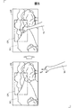
図16は別の実施形態のヘッドマウントディスプレイ100の概略構成を示す説明図である。この実施形態では、既述したカメラ61については、外景SCの撮像専用のカメラとし、ユーザーの手Yhの認識専用に用いるカメラ61aを画像表示部20の端部ERに備える。図17は画像表示部20の端部ERに位置するカメラ61aの撮像領域CRとユーザーの視野VRとの関係を概略的に示す説明図である。この図17に示すように、カメラ61aの撮像領域CRは、カメラ配設位置の関係から、ユーザーの視野VRの右端側の領域もしくは視野VRから外れた領域となる。このため、撮像領域CRに入り込んだ手Yhは、視野VRを占める外景SCに殆ど入らないようになり、外景SCはさほど手Yhで遮られないので、ユーザーは、手Yhで邪魔されずに、外景SCを眺めて愉しむことができる。なお、カメラ61aを端部ELに備えるようにしてもよく、カメラ61aの向きを下向きにして、その撮像領域CRをユーザーの視野VRの下方側にしてもよい。こうした実施形態のヘッドマウントディスプレイ100は、カメラ61aの撮像領域CRにユーザーの手Yhが入り込んだことを、次のように、ユーザーに認知する。図18はカメラ61aの撮像領域CRがユーザーの視野VRから外れた場合の手の検出手法の概要を示す説明図である。
A-6. Other embodiment-3:
FIG. 16 is an explanatory diagram showing a schematic configuration of a head mounted
図示するように、この実施形態では、カメラ61aの撮像領域CRの外にあった手Yhがこの撮像領域CRに入り込むと、図6で説明した手認識処理により、ユーザーの手Yhが認識される(ステップS112)。そうすると、AR処理部142は、図18の下段に図示したように、撮像領域CRに手Yhが入り込んで認識された旨を示す虚像VIを表示するための画像データーを生成し、その画像データーにより、視野VRの右上に、虚像VIを表示する。これにより、ユーザーは、カメラ61aの撮像領域CRの外にあった手Yhがこの撮像領域CRに入り込んだことを認知できるので、その後の手の挙動を何らかのコマンド動作とできる。例えば、図18の下段に示すように虚像VIを表示した後、ユーザーが手Yhを動かせば、この動きを制御部10が検出することで、図11に示した虚像VIを、ポインターPおよび矩形枠VIfを含んで表示するようにでき、ポインターPによるコマンドの実行が可能となる。図18に示す虚像VIは、図11に示した矩形形状の虚像VIと共に表示したり、矩形形状の虚像VIに含まれるように表示してもよい。
As shown in the drawing, in this embodiment, when the hand Yh outside the imaging region CR of the
B.変形例:
上記実施形態において、ハードウェアによって実現されるとした構成の一部をソフトウェアに置き換えるようにしてもよく、逆に、ソフトウェアによって実現されるとした構成の一部をハードウェアに置き換えるようにしてもよい。その他、以下のような変形も可能である。
B. Variations:
In the above embodiment, a part of the configuration realized by hardware may be replaced by software, and conversely, a part of the configuration realized by software may be replaced by hardware. Good. In addition, the following modifications are possible.
・変形例1:
上記実施形態では、ヘッドマウントディスプレイの構成について例示した。しかし、ヘッドマウントディスプレイの構成は、本発明の要旨を逸脱しない範囲において任意に定めることが可能であり、例えば、各構成部の追加・削除・変換等を行うことができる。
・ Modification 1:
In the said embodiment, it illustrated about the structure of the head mounted display. However, the configuration of the head-mounted display can be arbitrarily determined without departing from the gist of the present invention. For example, each component can be added, deleted, converted, and the like.
上記実施形態における、制御部と、画像表示部とに対する構成要素の割り振りは、あくまで一例であり、種々の態様を採用可能である。例えば、以下のような態様としてもよい。(i)制御部にCPUやメモリー等の処理機能を搭載、画像表示部には表示機能のみを搭載する態様、(ii)制御部と画像表示部との両方にCPUやメモリー等の処理機能を搭載する態様、(iii)制御部と画像表示部とを一体化した態様(例えば、画像表示部に制御部が含まれ眼鏡型のウェアラブルコンピューターとして機能する態様)、(iv)制御部の代わりにスマートフォンや携帯型ゲーム機を使用する態様、(v)制御部と画像表示部とを無線通信かつワイヤレス給電可能な構成とすることにより接続部(コード)を廃した態様。 The allocation of components to the control unit and the image display unit in the above embodiment is merely an example, and various aspects can be employed. For example, the following aspects may be adopted. (I) A mode in which processing functions such as a CPU and a memory are mounted on the control unit, and only a display function is mounted on the image display unit. (Iii) a mode in which the control unit and the image display unit are integrated (for example, a mode in which the control unit is included in the image display unit and functions as a glasses-type wearable computer), (iv) instead of the control unit A mode in which a smartphone or a portable game machine is used, and (v) a mode in which the connection unit (code) is eliminated by adopting a configuration in which the control unit and the image display unit can perform wireless communication and wireless power feeding.
上記実施形態では、説明の便宜上、制御部が送信部を備え、画像表示部が受信部を備えるものとした。しかし、上記実施形態の送信部および受信部は、いずれも、双方向通信が可能な機能を備えており、送受信部として機能することができる。また、例えば、図2に示した制御部は、有線の信号伝送路を介して画像表示部と接続されているものとした。しかし、制御部と、画像表示部とは、無線LANや赤外線通信やBluetooth(登録商標)等の無線の信号伝送路を介した接続により接続されていてもよい。 In the above embodiment, for convenience of explanation, the control unit includes a transmission unit, and the image display unit includes a reception unit. However, each of the transmission unit and the reception unit of the above-described embodiment has a function capable of bidirectional communication, and can function as a transmission / reception unit. For example, the control unit shown in FIG. 2 is connected to the image display unit via a wired signal transmission path. However, the control unit and the image display unit may be connected by a connection via a wireless signal transmission path such as a wireless LAN, infrared communication, or Bluetooth (registered trademark).
例えば、図2に示した制御部、画像表示部の構成は任意に変更することができる。具体的には、例えば、制御部からタッチパッドを省略し、十字キーのみで操作する構成としてもよい。また、制御部に操作用スティック等の他の操作用インターフェイスを備えても良い。また、制御部にはキーボードやマウス等のデバイスを接続可能な構成として、キーボードやマウスから入力を受け付けるものとしてもよい。また、例えば、タッチパッドや十字キーによる操作入力のほか、フットスイッチ(ユーザーの足により操作するスイッチ)による操作入力を取得してもよい。また、フットスイッチや視線による操作入力を取得可能とすれば、ユーザーが手を離すことが困難である作業においても、入力情報取得部は、ユーザーからの操作入力を取得することができる。 For example, the configurations of the control unit and the image display unit illustrated in FIG. 2 can be arbitrarily changed. Specifically, for example, the touch pad may be omitted from the control unit, and the operation may be performed using only the cross key. Further, the control unit may be provided with another operation interface such as an operation stick. Moreover, it is good also as what receives an input from a keyboard or a mouse | mouth as a structure which can connect devices, such as a keyboard and a mouse | mouth, to a control part. Further, for example, in addition to an operation input using a touch pad or a cross key, an operation input using a foot switch (a switch operated by a user's foot) may be acquired. In addition, if it is possible to acquire an operation input using a foot switch or a line of sight, the input information acquisition unit can acquire an operation input from the user even in a task in which it is difficult for the user to release his / her hand.
例えば、ヘッドマウントディスプレイは、両眼タイプの透過型ヘッドマウントディスプレイであるものとしたが、単眼タイプのヘッドマウントディスプレイとしてもよい。また、ユーザーがヘッドマウントディスプレイを装着した状態において外景の透過が遮断される非透過型ヘッドマウントディスプレイとして構成してもよい。 For example, the head mounted display is a binocular transmissive head mounted display, but may be a monocular head mounted display. Further, it may be configured as a non-transmissive head mounted display in which the transmission of the outside scene is blocked when the user wears the head mounted display.
図19は変形例におけるヘッドマウントディスプレイの外観の構成を示す説明図である。図19(A)の例の場合、図1に示したヘッドマウントディスプレイ100との違いは、画像表示部20aが、右光学像表示部26に代えて右光学像表示部26aを備える点と、左光学像表示部28に代えて左光学像表示部28aを備える点である。右光学像表示部26aは、第1実施形態の光学部材よりも小さく形成され、ヘッドマウントディスプレイの装着時におけるユーザーの右眼の斜め上に配置されている。同様に、左光学像表示部28aは、第1実施形態の光学部材よりも小さく形成され、ヘッドマウントディスプレイの装着時におけるユーザーの左眼の斜め上に配置されている。図19(B)の例の場合、図1に示したヘッドマウントディスプレイ100との違いは、画像表示部20bが、右光学像表示部26に代えて右光学像表示部26bを備える点と、左光学像表示部28に代えて左光学像表示部28bを備える点である。右光学像表示部26bは、第1実施形態の光学部材よりも小さく形成され、ヘッドマウントディスプレイの装着時におけるユーザーの右眼の斜め下に配置されている。左光学像表示部28bは、第1実施形態の光学部材よりも小さく形成され、ヘッドマウントディスプレイの装着時におけるユーザーの左眼の斜め下に配置されている。このように、光学像表示部はユーザーの眼の近傍に配置されていれば足りる。また、光学像表示部を形成する光学部材の大きさも任意であり、光学像表示部がユーザーの眼の一部分のみを覆う態様、換言すれば、光学像表示部がユーザーの眼を完全に覆わない態様のヘッドマウントディスプレイとして実現することもできる。
FIG. 19 is an explanatory diagram showing an external configuration of a head-mounted display in a modified example. In the case of the example of FIG. 19A, the difference from the head mounted
例えば、画像処理部、表示制御部、AR処理部、音声処理部等の機能部は、CPUがROMやハードディスクに格納されているコンピュータープログラムをRAMに展開して実行することにより実現されるものとして記載した。しかし、これら機能部は、当該機能を実現するために設計されたASIC(Application Specific Integrated Circuit:特定用途向け集積回路)を用いて構成されてもよい。 For example, functional units such as an image processing unit, a display control unit, an AR processing unit, and an audio processing unit are realized by the CPU developing and executing a computer program stored in the ROM or hard disk on the RAM. Described. However, these functional units may be configured using an ASIC (Application Specific Integrated Circuit) designed to realize the function.
例えば、上記実施形態では、画像表示部を眼鏡のように装着するヘッドマウントディスプレイであるとしているが、画像表示部が通常の平面型ディスプレイ装置(液晶ディスプレイ装置、プラズマディスプレイ装置、有機ELディスプレイ装置等)であるとしてもよい。この場合にも、制御部と画像表示部との間の接続は、有線の信号伝送路を介した接続であってもよいし、無線の信号伝送路を介した接続であってもよい。このようにすれば、制御部を、通常の平面型ディスプレイ装置のリモコンとして利用することもできる。 For example, in the above-described embodiment, it is assumed that the image display unit is a head mounted display that is mounted like glasses, but the image display unit is a normal flat display device (liquid crystal display device, plasma display device, organic EL display device, etc. ). Also in this case, the connection between the control unit and the image display unit may be a connection via a wired signal transmission path or a connection via a wireless signal transmission path. If it does in this way, a control part can also be utilized as a remote control of a usual flat type display device.
また、画像表示部として、眼鏡のように装着する画像表示部に代えて、例えば帽子のように装着する画像表示部といった他の形状の画像表示部を採用してもよい。また、イヤホンは耳掛け型やヘッドバンド型を採用してもよく、省略しても良い。また、例えば、自動車や飛行機等の車両に搭載されるヘッドアップディスプレイ(HUD、Head-Up Display)として構成されてもよい。また、例えば、ヘルメット等の身体防護具に内蔵されたヘッドマウントディスプレイとして構成されてもよい。 Further, as the image display unit, instead of the image display unit worn like glasses, an image display unit of another shape such as an image display unit worn like a hat may be adopted. Further, the earphone may be an ear-hook type or a headband type, or may be omitted. Further, for example, it may be configured as a head-up display (HUD, Head-Up Display) mounted on a vehicle such as an automobile or an airplane. Further, for example, it may be configured as a head-mounted display built in a body protective device such as a helmet.
例えば、上記実施形態では、電源として二次電池を用いることしたが、電源としては二次電池に限らず、種々の電池を使用することができる。例えば、一次電池や、燃料電池、太陽電池、熱電池等を使用してもよい。 For example, in the above-described embodiment, the secondary battery is used as the power source. However, the power source is not limited to the secondary battery, and various batteries can be used. For example, a primary battery, a fuel cell, a solar cell, a thermal cell, or the like may be used.
例えば、上記実施形態では、画像光生成部は、バックライトと、バックライト制御部と、LCDと、LCD制御部とを用いて構成されるものとした。しかし、上記の態様はあくまで例示である。画像光生成部は、これらの構成部と共に、またはこれらの構成部に代えて、他の方式を実現するための構成部を備えていても良い。例えば、画像光生成部は、有機EL(有機エレクトロルミネッセンス、Organic Electro-Luminescence)のディスプレイと、有機EL制御部とを備える構成としても良い。また、例えば、画像生成部は、LCDに代えてデジタル・マイクロミラー・デバイス等を用いることもできる。また、例えば、レーザー網膜投影型の頭部装着型表示装置に対して本発明を適用することも可能である。 For example, in the above embodiment, the image light generation unit is configured using a backlight, a backlight control unit, an LCD, and an LCD control unit. However, the above aspect is merely an example. The image light generation unit may include a configuration unit for realizing another method together with or in place of these configuration units. For example, the image light generation unit may include an organic EL (Organic Electro-Luminescence) display and an organic EL control unit. Further, for example, the image generation unit can use a digital micromirror device or the like instead of the LCD. Further, for example, the present invention can be applied to a laser retinal projection type head-mounted display device.
・他の変形例:
上記した実施形態では、図14で説明したように、撮像領域CRに入り込み済みの手Yhが外周縁領域CRfに達した以降においては、撮像領域CRの最外周縁に近づくほど高周波数域の警告音を発するようにしたが、これに限られない。例えば、手Yhが外周縁領域CRfに達した以降に撮像領域CRの最外周縁に近づくほど高音量の警告音を発するようにしてもよい。また、警告音を音がパルス状に発せられるようにした上で、手Yhが外周縁領域CRfに達した以降に撮像領域CRの最外周縁に近づくほど短周期のパルスで警告音を発するようにしてもよい。「手が認識範囲から外れそうです」等の音声案内を行うようにしてもよい。この他、音による報知に代えて、光放出、或いは、中耳に振動を伝えて音を認知させる骨伝導にて、報知するようにしてもよい。光放出による報知では、手Yhが撮像領域CRの最外周縁に近づくにつれて、異なる色の光を放出して報知したり、手Yhが外周縁領域CRfに達した以降に撮像領域CRの最外周縁に近づくほど短周期のパルスで光を発するようにしてもよい。骨伝導による報知では、手Yhが撮像領域CRの最外周縁に近づくほど高周波の音や高音量の音が伝わるようにしてもよい。また、レベルゲージを示す虚像VIをAR処理部142等にて表示し、そのレベルを、手Yhが撮像領域CRの最外周縁に近づくにつれて高めるようにしてもよい。手Yhが撮像領域CRの最外周縁に近づくにつれて、虚像VIにおけるポインターPを点滅させたり、ポインターPの色や形状を変えるようにしてもよい。この他、ヘッドマウントディスプレイ100とは別体であってユーザーの取り扱う機器、例えば制御部10(図1参照)や、図示しない携帯端末等が有する振動誘起部に制御信号を出力して制御部10や携帯端末等に振動を誘起し、その振動により報知するようにしてもよい。この場合には、手Yhが撮像領域CRに達した以降に撮像領域CRの最外周縁に近づくほど短周期の振動を携帯端末等に振動を誘起するようにしてもよい。頭部に装着される画像表示部20それ自体に振動を誘起してもよい。
・ Other variations:
In the above-described embodiment, as described with reference to FIG. 14, after the hand Yh that has already entered the imaging region CR reaches the outer peripheral region CRf, the warning in the high frequency region becomes closer to the outermost peripheral edge of the imaging region CR. I made a sound, but it is not limited to this. For example, after the hand Yh reaches the outer peripheral area CRf, a higher volume warning sound may be emitted as it approaches the outermost peripheral edge of the imaging area CR. Further, after the warning sound is emitted in a pulse shape, the warning sound is emitted with a short-period pulse as the hand Yh reaches the outer peripheral edge region CRf and approaches the outermost peripheral edge of the imaging region CR. It may be. You may make it perform voice guidance, such as "It is likely that a hand will come out of a recognition range." In addition, instead of the notification by sound, the notification may be performed by light emission or bone conduction that transmits vibration to the middle ear to recognize the sound. In the notification by light emission, as the hand Yh approaches the outermost peripheral edge of the imaging region CR, the notification is performed by emitting light of a different color or after the hand Yh reaches the outer peripheral region CRf. You may make it emit light by a short period pulse, so that it approaches a periphery. In the notification by bone conduction, a higher frequency sound or a higher volume sound may be transmitted as the hand Yh approaches the outermost peripheral edge of the imaging region CR. Further, a virtual image VI indicating a level gauge may be displayed on the
上記した実施形態のヘッドマウントディスプレイ100において、図6によるユーザーの手Yhの認識が所定の期間に亘ってなされないと、図11に示す矩形枠VIfのみの虚像VI或いは矩形枠VIfを含む虚像VIを、AR処理部142等にてユーザーに視認させるようにしてもよい。こうすれば、撮像領域CRにユーザーの手Yhが入っていないことをユーザーに確実に認知させて、自身の手Yhを外周縁領域CRfより内側の撮像領域CRに入り込むようユーザーに促すことができるので、ユーザーの手Yhの検出確度が高まる。なお、図11に示す矩形枠VIfのみの虚像VI或いは矩形枠VIfを含む虚像VIを、何らかの操作、例えば、ユーザーによるタッチパッド14のタッチ操作をトリガーに表示するようにしてもよい。
In the head-mounted
この他、AR処理部は、カメラによって取得されたユーザーの視界方向の外景画像を、画素視差角によりパターンマッチングさせて、拡張現実処理を実現してもよい。具体的には、画像表示部は、右眼用カメラと、左眼用カメラとを備える構成とする。右眼用カメラは、画像表示部のユーザーの右眼に対応する位置に配置され、画像表示部の表側方向の外景を撮像可能なカメラである。左眼用カメラは、画像表示部のユーザーの左眼に対応する位置に配置され、画像表示部の表側方向の外景を撮像可能なカメラである。AR処理部は、右眼用カメラにより撮像された画像に含まれる対象物体(付加提示用の情報を近傍に表示させる対象となる物体)と、左眼用カメラにより撮像された画像に含まれる対象物体との間のずれ量を求め、当該ずれ量と画素視差角とを用いて、拡張現実処理における虚像VIの表示箇所たる「目標距離」を決定してもよい。 In addition, the AR processing unit may implement augmented reality processing by pattern matching the outside scene image in the user's field of view acquired by the camera with the pixel parallax angle. Specifically, the image display unit includes a right-eye camera and a left-eye camera. The right-eye camera is a camera that is disposed at a position corresponding to the right eye of the user of the image display unit and can capture an outside scene in the front side direction of the image display unit. The left-eye camera is a camera that is arranged at a position corresponding to the left eye of the user of the image display unit and can capture an outside scene in the front side direction of the image display unit. The AR processing unit includes a target object included in an image captured by the right-eye camera (an object for displaying additional presentation information in the vicinity) and a target included in the image captured by the left-eye camera. The amount of deviation from the object may be obtained, and the “target distance” that is the display location of the virtual image VI in the augmented reality process may be determined using the amount of deviation and the pixel parallax angle.
AR処理部は、上記の拡張現実処理を、所定の条件が満足される場合に限って実行してもよい。例えば、画像表示部に対してユーザーの視線の方向を検出可能な構成を備えたうえで、AR処理部は、検出された視線の方向が以下の条件のうちの少なくともいずれか1つを満たす場合に限って、上記の拡張現実処理を実行してもよい。
・水平約200°、垂直約125°(例えば、下方向75°、上方向50°)の視野角の範囲内であるとき。
・情報受容能力に優れる有効視野である、水平約30°、垂直約20°の範囲内であるとき。
・注視点が迅速に安定して見える安定注視野である、水平60°〜90°、垂直45°〜70°の範囲内であるとき。
・映像に誘発される自己運動感覚(ベクション)の誘発が起こりはじめる水平約20°から、自己運動感覚が飽和する約110°の範囲内であるとき。
The AR processing unit may execute the augmented reality process only when a predetermined condition is satisfied. For example, the AR processing unit has a configuration capable of detecting the direction of the user's line of sight with respect to the image display unit, and the AR processing unit satisfies at least one of the following conditions: Only the augmented reality process may be executed.
When the viewing angle is within a range of about 200 ° horizontal and about 125 ° vertical (for example, 75 ° downward and 50 ° upward).
-When it is within the range of about 30 ° in the horizontal direction and about 20 ° in the vertical direction, which is an effective visual field with excellent information receiving ability.
-When the gazing point is within the range of 60 ° to 90 ° horizontal and 45 ° to 70 ° vertical, which is a stable gazing field that appears quickly and stably.
-When the self-motion sensation (vection) induced by the image is within a range from about 20 ° where the induction of self-motion sensation begins to about 110 ° where the self-motion sense saturates.
また、上記の実施形態では、ユーザーの手Yhの認識に撮像素子を備えるカメラ61を用いたが、頭部に装着される画像表示部20に、超音波センサーや赤外線センサー、光センサー等を設けて、これらセンサー出力から、ユーザーの手を認識し、その認識した手がカメラ61の撮像領域CRを外れそうになると、既述したように報知するようにしてもよい。
In the above-described embodiment, the
また、上記の実施形態のヘッドマウントディスプレイ100では、撮像領域CRに入り込んだユーザーの手Yhを認識するに当たり、カメラ61が備える画素ごとに入力を受けた隣接画素の間の画素値の差分算出を行ったが(ステップS102)、撮像領域CRに入り込んで撮像されるに到った何らかの輪郭捕捉対象物の撮像画像を含む近傍領域について、隣接画素の間の画素値の差分算出を行ったり、この近傍領域を占める画素から得られる色についてのデーターの差分算出を行うようにしてもよい。上記の近傍領域を占める画素についての差分演算とすれば、図8に示すように映り込んだ雲や山並み、木々等の静止物については、差分演算を経た輪郭形状の捕捉対象から除外できるので、その分、演算負荷が軽減する。
Further, in the head mounted
本発明は、上述の実施形態や実施例、変形例に限られるものではなく、その趣旨を逸脱しない範囲において種々の構成で実現することができる。例えば、発明の概要の欄に記載した各形態中の技術的特徴に対応する実施形態、実施例、変形例中の技術的特徴は、上述の課題の一部または全部を解決するために、あるいは、上述の効果の一部または全部を達成するために、適宜、差し替えや組み合わせを行うことが可能である。また、その技術的特徴が本明細書中に必須なものとして説明されていなければ、適宜、削除することが可能である。 The present invention is not limited to the above-described embodiments, examples, and modifications, and can be realized with various configurations without departing from the spirit thereof. For example, the technical features in the embodiments, examples, and modifications corresponding to the technical features in each embodiment described in the summary section of the invention are to solve some or all of the above-described problems, or In order to achieve part or all of the above-described effects, replacement or combination can be performed as appropriate. Further, if the technical feature is not described as essential in the present specification, it can be deleted as appropriate.
10…制御部(コントローラー)
12…点灯部
14…タッチパッド
16…十字キー
18…電源スイッチ
20…画像表示部
20a、20b…画像表示部
21…右保持部
22…右表示駆動部
23…左保持部
24…左表示駆動部
26…右光学像表示部
26a、26b…右光学像表示部
28…左光学像表示部
28a、28b…左光学像表示部
30…イヤホンプラグ
32…右イヤホン
34…左イヤホン
40…接続部
42…右コード
44…左コード
46…連結部材
48…本体コード
51…送信部
52…送信部
53…受信部
61、61a…カメラ
100…ヘッドマウントディスプレイ(頭部装着型表示装置)
110…入力情報取得部
120…記憶部
122…手輪郭形状記憶部
130…電源
132…無線通信部
140…CPU
142…AR処理部(拡張現実処理部)
160…画像処理部
170…音声処理部
180…インターフェイス
190…表示制御部
201…右バックライト制御部
202…左バックライト制御部
221…右バックライト
222…左バックライト
251…右投写光学系
252…左投写光学系
261…右導光板
262…左導光板
PCLK…クロック信号
VSync…垂直同期信号
HSync…水平同期信号
Data…画像データー
Data1…右眼用画像データー
Data2…左眼用画像データー
CR…撮像領域
CRf…外周縁領域
CR11〜CR22…分割領域
CRD…下端領域
CRL…左端領域
CRR…右端領域
CRU…残余領域
P…ポインター
PC…パーソナルコンピューター
SC…外景
RE…右眼
LE…左眼
VI…虚像
VIf…矩形枠
EL…端部
AP…先端部
ER…端部
VR…視野
Yh…手
Li…画素列
10. Control unit (controller)
DESCRIPTION OF
DESCRIPTION OF
142 ... AR processing unit (augmented reality processing unit)
DESCRIPTION OF
Claims (5)
前記虚像を表示するための画像データーを生成し、該生成した前記画像データーにより、前記虚像がユーザーの視野に表示されるように前記虚像を視認させる拡張現実処理部と、
ユーザーの手を検出する所定の検出領域に入り込んだ前記ユーザーの手を検出し、前記検出領域における前記ユーザーの手の挙動を検出する検出部と、
該検出部の検出した前記ユーザーの手の挙動に基づいて、前記ユーザーの手が前記検出領域の外周縁をなす外周縁領域に達すると、前記ユーザーに報知する報知部とを備え、
前記拡張現実処理部は、
前記検出領域の外周縁をなす前記外周縁領域に対応した枠形状が含まれた前記虚像を表示するための前記画像データーを生成して、前記虚像をユーザーに視認させる、頭部装着型表示装置。 A head-mounted display device that allows a user to view a virtual image superimposed on an outside scene,
An augmented reality processing unit that generates image data for displaying the virtual image, and causes the virtual image to be viewed by the generated image data so that the virtual image is displayed in a user's field of view;
A detection unit for detecting the user's hand that has entered a predetermined detection area for detecting a user's hand, and detecting a behavior of the user's hand in the detection area;
Based on the detected behavior of the user's hands in the detection unit, when the user's hand reaches to the outer peripheral edge region forming the outer periphery of the detection area, e Bei a notification unit for informing the user,
The augmented reality processing unit
A head-mounted display device that generates the image data for displaying the virtual image including a frame shape corresponding to the outer peripheral area forming the outer peripheral edge of the detection area, and allows the user to visually recognize the virtual image. .
前記虚像を前記検出領域に対応した表示域で視認させると共に、
前記検出部が前記検出領域に入り込んだ前記ユーザーの手を検出すると、該検出された前記ユーザーの手の少なくとも一部部位に対応する手部位対応画像が組み込まれた前記虚像を表示するための前記画像データーを生成し、前記虚像の表示域において前記手部位対応画像が占める位置を、前記検出領域において前記一部部位が占める位置に応じて更新する、請求項1記載の頭部装着型表示装置。 The augmented reality processing unit
While making the virtual image visible in a display area corresponding to the detection area,
When the detection unit detects the user's hand that has entered the detection area, the virtual image including the hand part corresponding image corresponding to at least a part of the detected user's hand is displayed. The head-mounted display device according to claim 1, wherein image data is generated, and a position occupied by the hand part corresponding image in the display area of the virtual image is updated according to a position occupied by the partial part in the detection area. .
前記検出部が前記検出領域に入り込んだ前記ユーザーの手を検出すると、前記ユーザーの手の検出済みの旨を表す検出完了画像を前記虚像として表示するための前記画像データー、或いは、前記検出完了画像が組み込まれた前記虚像を表示するための前記画像データーを生成して、前記虚像をユーザーに視認させる請求項1または請求項2に記載の頭部装着型表示装置。 The augmented reality processing unit
When the detection unit detects the user's hand entering the detection area, the image data for displaying a detection completion image representing the detection of the user's hand as the virtual image, or the detection completion image and generating the image data for displaying the virtual image is incorporated, head-mounted display device according to claim 1 or billed to claim 2 allows the user to visually recognize the virtual image to the user.
Priority Applications (5)
| Application Number | Priority Date | Filing Date | Title |
|---|---|---|---|
| JP2013177866A JP6237000B2 (en) | 2013-08-29 | 2013-08-29 | Head-mounted display device |
| US14/466,179 US9690371B2 (en) | 2013-08-29 | 2014-08-22 | Head mounted display apparatus |
| CN201910003691.3A CN110068926B (en) | 2013-08-29 | 2014-08-28 | Display device |
| CN201410432731.3A CN104423045B (en) | 2013-08-29 | 2014-08-28 | Head-mount type display unit |
| US15/606,844 US10133344B2 (en) | 2013-08-29 | 2017-05-26 | Head mounted display apparatus |
Applications Claiming Priority (1)
| Application Number | Priority Date | Filing Date | Title |
|---|---|---|---|
| JP2013177866A JP6237000B2 (en) | 2013-08-29 | 2013-08-29 | Head-mounted display device |
Publications (3)
| Publication Number | Publication Date |
|---|---|
| JP2015045805A JP2015045805A (en) | 2015-03-12 |
| JP2015045805A5 JP2015045805A5 (en) | 2016-10-13 |
| JP6237000B2 true JP6237000B2 (en) | 2017-11-29 |
Family
ID=52582487
Family Applications (1)
| Application Number | Title | Priority Date | Filing Date |
|---|---|---|---|
| JP2013177866A Active JP6237000B2 (en) | 2013-08-29 | 2013-08-29 | Head-mounted display device |
Country Status (3)
| Country | Link |
|---|---|
| US (2) | US9690371B2 (en) |
| JP (1) | JP6237000B2 (en) |
| CN (2) | CN104423045B (en) |
Cited By (2)
| Publication number | Priority date | Publication date | Assignee | Title |
|---|---|---|---|---|
| US10289194B2 (en) | 2017-03-06 | 2019-05-14 | Universal City Studios Llc | Gameplay ride vehicle systems and methods |
| US11200656B2 (en) | 2019-01-11 | 2021-12-14 | Universal City Studios Llc | Drop detection systems and methods |
Families Citing this family (34)
| Publication number | Priority date | Publication date | Assignee | Title |
|---|---|---|---|---|
| WO2015105347A1 (en) * | 2014-01-09 | 2015-07-16 | Samsung Electronics Co., Ltd. | Wearable display apparatus |
| US10257494B2 (en) | 2014-09-22 | 2019-04-09 | Samsung Electronics Co., Ltd. | Reconstruction of three-dimensional video |
| US11205305B2 (en) | 2014-09-22 | 2021-12-21 | Samsung Electronics Company, Ltd. | Presentation of three-dimensional video |
| US20160092726A1 (en) * | 2014-09-30 | 2016-03-31 | Xerox Corporation | Using gestures to train hand detection in ego-centric video |
| JP6609920B2 (en) * | 2014-12-25 | 2019-11-27 | セイコーエプソン株式会社 | Display device and control method of display device |
| JP6478713B2 (en) * | 2015-03-04 | 2019-03-06 | キヤノン株式会社 | Measuring device and measuring method |
| JP6464889B2 (en) * | 2015-03-31 | 2019-02-06 | 富士通株式会社 | Image processing apparatus, image processing program, and image processing method |
| JP2016192122A (en) * | 2015-03-31 | 2016-11-10 | ソニー株式会社 | Information processing device, information processing method, and program |
| JP6467039B2 (en) * | 2015-05-21 | 2019-02-06 | 株式会社ソニー・インタラクティブエンタテインメント | Information processing device |
| US10409443B2 (en) * | 2015-06-24 | 2019-09-10 | Microsoft Technology Licensing, Llc | Contextual cursor display based on hand tracking |
| CN105093533A (en) * | 2015-08-20 | 2015-11-25 | 余剑锋 | Virtual reality helmet device |
| JP6786792B2 (en) | 2015-12-03 | 2020-11-18 | セイコーエプソン株式会社 | Information processing device, display device, information processing method, and program |
| JP6363587B2 (en) | 2015-12-14 | 2018-07-25 | 株式会社ソニー・インタラクティブエンタテインメント | Information processing apparatus and warning presenting method |
| US10019844B1 (en) * | 2015-12-15 | 2018-07-10 | Oculus Vr, Llc | Display non-uniformity calibration for a virtual reality headset |
| CN113542602A (en) * | 2016-06-20 | 2021-10-22 | 麦克赛尔株式会社 | Image pickup apparatus, display apparatus, and image pickup display system |
| US10302482B2 (en) | 2016-10-07 | 2019-05-28 | Microsoft Technology Licensing, Llc | Dynamic sensor performance adjustment |
| US11460915B2 (en) * | 2017-03-10 | 2022-10-04 | Brainlab Ag | Medical augmented reality navigation |
| CN107067408B (en) * | 2017-04-11 | 2020-01-31 | 广西科技大学 | Image contour detection method for simulating human eye micromotion |
| JP6929114B2 (en) * | 2017-04-24 | 2021-09-01 | キヤノン株式会社 | Photoelectric conversion device and imaging system |
| US20190066385A1 (en) * | 2017-08-31 | 2019-02-28 | Canon Kabushiki Kaisha | Image processing apparatus, image processing method, and non-transitory computer-readable storage medium |
| CN109491496A (en) * | 2017-09-12 | 2019-03-19 | 精工爱普生株式会社 | The control method of head-mount type display unit and head-mount type display unit |
| DE102018201661A1 (en) | 2018-02-05 | 2019-08-08 | Audi Ag | A method for superimposing a virtual graphic object on a real environment by means of an augmented reality AR display device and motor vehicle |
| CN110149458A (en) * | 2018-02-13 | 2019-08-20 | 中兴通讯股份有限公司 | The method and apparatus that augmented reality visual element is shown |
| US10497179B2 (en) * | 2018-02-23 | 2019-12-03 | Hong Kong Applied Science and Technology Research Institute Company Limited | Apparatus and method for performing real object detection and control using a virtual reality head mounted display system |
| JP7239132B2 (en) * | 2018-03-30 | 2023-03-14 | Necソリューションイノベータ株式会社 | MOTION DETERMINATION DEVICE, MOTION DETERMINATION METHOD, AND PROGRAM |
| US10721510B2 (en) | 2018-05-17 | 2020-07-21 | At&T Intellectual Property I, L.P. | Directing user focus in 360 video consumption |
| US10482653B1 (en) | 2018-05-22 | 2019-11-19 | At&T Intellectual Property I, L.P. | System for active-focus prediction in 360 video |
| US10827225B2 (en) | 2018-06-01 | 2020-11-03 | AT&T Intellectual Propety I, L.P. | Navigation for 360-degree video streaming |
| JP6634654B2 (en) * | 2018-06-28 | 2020-01-22 | 株式会社ソニー・インタラクティブエンタテインメント | Information processing apparatus and warning presentation method |
| KR20200080047A (en) | 2018-12-26 | 2020-07-06 | 삼성전자주식회사 | Method and wearable device for identifying hand of truly user |
| FR3093578A1 (en) * | 2019-03-05 | 2020-09-11 | Orange | Method and device for processing data in a virtual reality environment. |
| JP6797429B2 (en) * | 2019-04-18 | 2020-12-09 | 株式会社スポーツネット | goggles |
| JP6867464B2 (en) * | 2019-11-28 | 2021-04-28 | 株式会社ソニー・インタラクティブエンタテインメント | Information processing device and warning presentation method |
| CN112817445A (en) * | 2021-01-25 | 2021-05-18 | 暗物智能科技(广州)有限公司 | Information acquisition method and device, electronic equipment and storage medium |
Family Cites Families (12)
| Publication number | Priority date | Publication date | Assignee | Title |
|---|---|---|---|---|
| JPH03177918A (en) * | 1989-12-07 | 1991-08-01 | Mitsubishi Electric Corp | Cursor control system |
| JP3819096B2 (en) * | 1997-01-22 | 2006-09-06 | 株式会社東芝 | User interface device and operation range presentation method |
| JP2006154900A (en) * | 2004-11-25 | 2006-06-15 | Olympus Corp | Hand-written image display system, and portable information terminal for space hand-writing |
| JP2010145861A (en) * | 2008-12-19 | 2010-07-01 | Brother Ind Ltd | Head mount display |
| JP5262681B2 (en) | 2008-12-22 | 2013-08-14 | ブラザー工業株式会社 | Head mounted display and program thereof |
| JP5207145B2 (en) * | 2009-12-24 | 2013-06-12 | ブラザー工業株式会社 | Head mounted display |
| JP5779923B2 (en) * | 2011-03-17 | 2015-09-16 | ソニー株式会社 | Information processing apparatus, information processing method, and computer program |
| JP5930618B2 (en) * | 2011-06-20 | 2016-06-08 | コニカミノルタ株式会社 | Spatial handwriting system and electronic pen |
| US20130342572A1 (en) * | 2012-06-26 | 2013-12-26 | Adam G. Poulos | Control of displayed content in virtual environments |
| US20140152558A1 (en) * | 2012-11-30 | 2014-06-05 | Tom Salter | Direct hologram manipulation using imu |
| US10025486B2 (en) * | 2013-03-15 | 2018-07-17 | Elwha Llc | Cross-reality select, drag, and drop for augmented reality systems |
| JP6217244B2 (en) * | 2013-08-29 | 2017-10-25 | セイコーエプソン株式会社 | Image processing apparatus, head-mounted display apparatus having the same, image processing method, and computer program |
-
2013
- 2013-08-29 JP JP2013177866A patent/JP6237000B2/en active Active
-
2014
- 2014-08-22 US US14/466,179 patent/US9690371B2/en active Active
- 2014-08-28 CN CN201410432731.3A patent/CN104423045B/en active Active
- 2014-08-28 CN CN201910003691.3A patent/CN110068926B/en active Active
-
2017
- 2017-05-26 US US15/606,844 patent/US10133344B2/en active Active
Cited By (6)
| Publication number | Priority date | Publication date | Assignee | Title |
|---|---|---|---|---|
| US10289194B2 (en) | 2017-03-06 | 2019-05-14 | Universal City Studios Llc | Gameplay ride vehicle systems and methods |
| US10528123B2 (en) | 2017-03-06 | 2020-01-07 | Universal City Studios Llc | Augmented ride system and method |
| US10572000B2 (en) | 2017-03-06 | 2020-02-25 | Universal City Studios Llc | Mixed reality viewer system and method |
| US11200656B2 (en) | 2019-01-11 | 2021-12-14 | Universal City Studios Llc | Drop detection systems and methods |
| US11200655B2 (en) | 2019-01-11 | 2021-12-14 | Universal City Studios Llc | Wearable visualization system and method |
| US11210772B2 (en) | 2019-01-11 | 2021-12-28 | Universal City Studios Llc | Wearable visualization device systems and methods |
Also Published As
| Publication number | Publication date |
|---|---|
| US9690371B2 (en) | 2017-06-27 |
| CN110068926A (en) | 2019-07-30 |
| CN110068926B (en) | 2022-01-18 |
| CN104423045B (en) | 2019-01-15 |
| US10133344B2 (en) | 2018-11-20 |
| US20170262047A1 (en) | 2017-09-14 |
| US20150062000A1 (en) | 2015-03-05 |
| JP2015045805A (en) | 2015-03-12 |
| CN104423045A (en) | 2015-03-18 |
Similar Documents
| Publication | Publication Date | Title |
|---|---|---|
| JP6237000B2 (en) | Head-mounted display device | |
| JP6217244B2 (en) | Image processing apparatus, head-mounted display apparatus having the same, image processing method, and computer program | |
| US10175484B2 (en) | Head-mounted display device, control method for head-mounted display device, and computer program | |
| US9898868B2 (en) | Display device, method of controlling the same, and program | |
| US9411160B2 (en) | Head mounted display, control method for head mounted display, and image display system | |
| JP6337418B2 (en) | Head-mounted display device and method for controlling head-mounted display device | |
| US20160110921A1 (en) | Head mounted display, method of controlling head mounted display, and computer program | |
| JP6459380B2 (en) | Head-mounted display device, head-mounted display device control method, and computer program | |
| JP6488786B2 (en) | Head-mounted display device, head-mounted display device control method, and computer program | |
| JP6492673B2 (en) | Head-mounted display device, method for controlling head-mounted display device, computer program | |
| JP2016004340A (en) | Information distribution system, head-mounted type display device, control method of head-mounted type display device and computer program | |
| JP6600945B2 (en) | Head-mounted display device, head-mounted display device control method, and computer program | |
| US9799144B2 (en) | Head mounted display, and control method for head mounted display | |
| JP2016148968A (en) | Head-mounted display device, control system, method for controlling head-mounted display device, and computer program | |
| JP6427942B2 (en) | Head-mounted display device, control system, and head-mounted display device control method | |
| JP6303274B2 (en) | Head-mounted display device and method for controlling head-mounted display device | |
| JP2017091433A (en) | Head-mounted type display device, method of controlling head-mounted type display device, and computer program | |
| JP2015115848A (en) | Head-mounted type display device and method for controlling head-mounted type display device | |
| JP6268778B2 (en) | Head-mounted display device and method for controlling head-mounted display device | |
| JP2016033759A (en) | Display device, method for controlling display device, and program | |
| JP6135162B2 (en) | Head-mounted display device, head-mounted display device control method, and image display system | |
| JP2016109710A (en) | Head-mounted display system, control method of head-mounted display system, and computer program | |
| JP2016033763A (en) | Display device, method for controlling display device, and program | |
| JP6451222B2 (en) | Head-mounted display device, head-mounted display device control method, and computer program | |
| JP6287399B2 (en) | Head-mounted display device and method for controlling head-mounted display device |
Legal Events
| Date | Code | Title | Description |
|---|---|---|---|
| A521 | Request for written amendment filed |
Free format text: JAPANESE INTERMEDIATE CODE: A523 Effective date: 20160822 |
|
| A621 | Written request for application examination |
Free format text: JAPANESE INTERMEDIATE CODE: A621 Effective date: 20160822 |
|
| A977 | Report on retrieval |
Free format text: JAPANESE INTERMEDIATE CODE: A971007 Effective date: 20170518 |
|
| A131 | Notification of reasons for refusal |
Free format text: JAPANESE INTERMEDIATE CODE: A131 Effective date: 20170627 |
|
| A521 | Request for written amendment filed |
Free format text: JAPANESE INTERMEDIATE CODE: A523 Effective date: 20170810 |
|
| TRDD | Decision of grant or rejection written | ||
| A01 | Written decision to grant a patent or to grant a registration (utility model) |
Free format text: JAPANESE INTERMEDIATE CODE: A01 Effective date: 20171003 |
|
| A61 | First payment of annual fees (during grant procedure) |
Free format text: JAPANESE INTERMEDIATE CODE: A61 Effective date: 20171016 |
|
| R150 | Certificate of patent or registration of utility model |
Ref document number: 6237000 Country of ref document: JP Free format text: JAPANESE INTERMEDIATE CODE: R150 |