JP5980201B2 - Insertion guidance system for needles and medical components - Google Patents
Insertion guidance system for needles and medical components Download PDFInfo
- Publication number
- JP5980201B2 JP5980201B2 JP2013512046A JP2013512046A JP5980201B2 JP 5980201 B2 JP5980201 B2 JP 5980201B2 JP 2013512046 A JP2013512046 A JP 2013512046A JP 2013512046 A JP2013512046 A JP 2013512046A JP 5980201 B2 JP5980201 B2 JP 5980201B2
- Authority
- JP
- Japan
- Prior art keywords
- needle
- probe
- sensor
- magnetic
- catheter
- Prior art date
- Legal status (The legal status is an assumption and is not a legal conclusion. Google has not performed a legal analysis and makes no representation as to the accuracy of the status listed.)
- Active
Links
Images


Classifications
-
- A—HUMAN NECESSITIES
- A61—MEDICAL OR VETERINARY SCIENCE; HYGIENE
- A61B—DIAGNOSIS; SURGERY; IDENTIFICATION
- A61B17/00—Surgical instruments, devices or methods, e.g. tourniquets
- A61B17/34—Trocars; Puncturing needles
- A61B17/3403—Needle locating or guiding means
-
- A—HUMAN NECESSITIES
- A61—MEDICAL OR VETERINARY SCIENCE; HYGIENE
- A61B—DIAGNOSIS; SURGERY; IDENTIFICATION
- A61B34/00—Computer-aided surgery; Manipulators or robots specially adapted for use in surgery
- A61B34/20—Surgical navigation systems; Devices for tracking or guiding surgical instruments, e.g. for frameless stereotaxis
-
- A—HUMAN NECESSITIES
- A61—MEDICAL OR VETERINARY SCIENCE; HYGIENE
- A61B—DIAGNOSIS; SURGERY; IDENTIFICATION
- A61B34/00—Computer-aided surgery; Manipulators or robots specially adapted for use in surgery
- A61B34/25—User interfaces for surgical systems
-
- A—HUMAN NECESSITIES
- A61—MEDICAL OR VETERINARY SCIENCE; HYGIENE
- A61B—DIAGNOSIS; SURGERY; IDENTIFICATION
- A61B5/00—Measuring for diagnostic purposes; Identification of persons
- A61B5/06—Devices, other than using radiation, for detecting or locating foreign bodies ; determining position of probes within or on the body of the patient
- A61B5/061—Determining position of a probe within the body employing means separate from the probe, e.g. sensing internal probe position employing impedance electrodes on the surface of the body
- A61B5/062—Determining position of a probe within the body employing means separate from the probe, e.g. sensing internal probe position employing impedance electrodes on the surface of the body using magnetic field
-
- A—HUMAN NECESSITIES
- A61—MEDICAL OR VETERINARY SCIENCE; HYGIENE
- A61B—DIAGNOSIS; SURGERY; IDENTIFICATION
- A61B5/00—Measuring for diagnostic purposes; Identification of persons
- A61B5/24—Detecting, measuring or recording bioelectric or biomagnetic signals of the body or parts thereof
- A61B5/25—Bioelectric electrodes therefor
- A61B5/279—Bioelectric electrodes therefor specially adapted for particular uses
- A61B5/28—Bioelectric electrodes therefor specially adapted for particular uses for electrocardiography [ECG]
- A61B5/283—Invasive
-
- A—HUMAN NECESSITIES
- A61—MEDICAL OR VETERINARY SCIENCE; HYGIENE
- A61B—DIAGNOSIS; SURGERY; IDENTIFICATION
- A61B8/00—Diagnosis using ultrasonic, sonic or infrasonic waves
- A61B8/08—Detecting organic movements or changes, e.g. tumours, cysts, swellings
- A61B8/0833—Detecting organic movements or changes, e.g. tumours, cysts, swellings involving detecting or locating foreign bodies or organic structures
- A61B8/0841—Detecting organic movements or changes, e.g. tumours, cysts, swellings involving detecting or locating foreign bodies or organic structures for locating instruments
-
- A—HUMAN NECESSITIES
- A61—MEDICAL OR VETERINARY SCIENCE; HYGIENE
- A61B—DIAGNOSIS; SURGERY; IDENTIFICATION
- A61B90/00—Instruments, implements or accessories specially adapted for surgery or diagnosis and not covered by any of the groups A61B1/00 - A61B50/00, e.g. for luxation treatment or for protecting wound edges
- A61B90/90—Identification means for patients or instruments, e.g. tags
- A61B90/98—Identification means for patients or instruments, e.g. tags using electromagnetic means, e.g. transponders
-
- A—HUMAN NECESSITIES
- A61—MEDICAL OR VETERINARY SCIENCE; HYGIENE
- A61B—DIAGNOSIS; SURGERY; IDENTIFICATION
- A61B17/00—Surgical instruments, devices or methods, e.g. tourniquets
- A61B17/34—Trocars; Puncturing needles
- A61B17/3403—Needle locating or guiding means
- A61B2017/3413—Needle locating or guiding means guided by ultrasound
-
- A—HUMAN NECESSITIES
- A61—MEDICAL OR VETERINARY SCIENCE; HYGIENE
- A61B—DIAGNOSIS; SURGERY; IDENTIFICATION
- A61B34/00—Computer-aided surgery; Manipulators or robots specially adapted for use in surgery
- A61B34/20—Surgical navigation systems; Devices for tracking or guiding surgical instruments, e.g. for frameless stereotaxis
- A61B2034/2046—Tracking techniques
- A61B2034/2051—Electromagnetic tracking systems
-
- A—HUMAN NECESSITIES
- A61—MEDICAL OR VETERINARY SCIENCE; HYGIENE
- A61B—DIAGNOSIS; SURGERY; IDENTIFICATION
- A61B34/00—Computer-aided surgery; Manipulators or robots specially adapted for use in surgery
- A61B34/20—Surgical navigation systems; Devices for tracking or guiding surgical instruments, e.g. for frameless stereotaxis
- A61B2034/2046—Tracking techniques
- A61B2034/2063—Acoustic tracking systems, e.g. using ultrasound
-
- A—HUMAN NECESSITIES
- A61—MEDICAL OR VETERINARY SCIENCE; HYGIENE
- A61B—DIAGNOSIS; SURGERY; IDENTIFICATION
- A61B90/00—Instruments, implements or accessories specially adapted for surgery or diagnosis and not covered by any of the groups A61B1/00 - A61B50/00, e.g. for luxation treatment or for protecting wound edges
- A61B90/36—Image-producing devices or illumination devices not otherwise provided for
- A61B90/37—Surgical systems with images on a monitor during operation
- A61B2090/378—Surgical systems with images on a monitor during operation using ultrasound
-
- A—HUMAN NECESSITIES
- A61—MEDICAL OR VETERINARY SCIENCE; HYGIENE
- A61B—DIAGNOSIS; SURGERY; IDENTIFICATION
- A61B90/00—Instruments, implements or accessories specially adapted for surgery or diagnosis and not covered by any of the groups A61B1/00 - A61B50/00, e.g. for luxation treatment or for protecting wound edges
- A61B90/39—Markers, e.g. radio-opaque or breast lesions markers
- A61B2090/3954—Markers, e.g. radio-opaque or breast lesions markers magnetic, e.g. NMR or MRI
-
- A—HUMAN NECESSITIES
- A61—MEDICAL OR VETERINARY SCIENCE; HYGIENE
- A61B—DIAGNOSIS; SURGERY; IDENTIFICATION
- A61B8/00—Diagnosis using ultrasonic, sonic or infrasonic waves
- A61B8/46—Ultrasonic, sonic or infrasonic diagnostic devices with special arrangements for interfacing with the operator or the patient
- A61B8/461—Displaying means of special interest
-
- A—HUMAN NECESSITIES
- A61—MEDICAL OR VETERINARY SCIENCE; HYGIENE
- A61B—DIAGNOSIS; SURGERY; IDENTIFICATION
- A61B8/00—Diagnosis using ultrasonic, sonic or infrasonic waves
- A61B8/46—Ultrasonic, sonic or infrasonic diagnostic devices with special arrangements for interfacing with the operator or the patient
- A61B8/467—Ultrasonic, sonic or infrasonic diagnostic devices with special arrangements for interfacing with the operator or the patient characterised by special input means
Landscapes
- Health & Medical Sciences (AREA)
- Life Sciences & Earth Sciences (AREA)
- Surgery (AREA)
- Engineering & Computer Science (AREA)
- Animal Behavior & Ethology (AREA)
- Veterinary Medicine (AREA)
- Public Health (AREA)
- Biomedical Technology (AREA)
- Heart & Thoracic Surgery (AREA)
- Medical Informatics (AREA)
- Molecular Biology (AREA)
- General Health & Medical Sciences (AREA)
- Pathology (AREA)
- Nuclear Medicine, Radiotherapy & Molecular Imaging (AREA)
- Physics & Mathematics (AREA)
- Biophysics (AREA)
- Human Computer Interaction (AREA)
- Robotics (AREA)
- Radiology & Medical Imaging (AREA)
- Electromagnetism (AREA)
- Oral & Maxillofacial Surgery (AREA)
- Cardiology (AREA)
- Ultra Sonic Daignosis Equipment (AREA)
- Media Introduction/Drainage Providing Device (AREA)
- Infusion, Injection, And Reservoir Apparatuses (AREA)
- Knitting Machines (AREA)
Description
関連出願の相互参照
[0001]本出願は、2008年11月25日に出願した米国特許出願12/323,273号、名称「Integrated System for Intravascular Placement of a Catheter」の一部継続出願である。本出願は、2010年5月28日に出願した米国仮特許出願第61/349,771号、名称「Needle Insertion Guidance System」の利益も主張する。前述の出願のそれぞれは、参照により本明細書に組み込まれている。
Cross-reference of related applications
[0001] This application is a continuation-in-part application of US patent application Ser. No. 12 / 323,273, filed Nov. 25, 2008, entitled “Integrated System for Intravasular Placement of a Catheter. This application also claims the benefit of US Provisional Patent Application No. 61 / 349,771, filed on May 28, 2010, entitled “Needle Insertion Guidance System”. Each of the foregoing applications is incorporated herein by reference.
本発明の目的は、カテーテルを患者の血管系内に正確に配置することのできる誘導システムを提供することにある。 It is an object of the present invention to provide a guidance system that can accurately place a catheter within a patient's vasculature.
[0002]簡単に要約すると、本発明の実施形態は、カテーテルを患者の血管系内に正確に配置するように構成された、統合型カテーテル配置システムを対象とする。統合システムは、カテーテル配置精度を改善するために、少なくとも2つのモダリティを採用しており、1つは、1)患者の血管系内にカテーテルを導入するための超音波補助誘導(ultrasound-assisted guidance)であり、もう1つは、2)先端位置特定システム(「TLS」)、すなわち前進中のいかなる先端位置異常をも検出してその修正を容易にするための、血管系内を前進中の、磁気に基づく(例えば、永久磁石(複数可)または電磁石(複数可)を介した)カテーテル先端の追跡である。 [0002] Briefly summarized, embodiments of the present invention are directed to an integrated catheter placement system configured to accurately place a catheter within a patient's vasculature. The integrated system employs at least two modalities to improve catheter placement accuracy, 1) ultrasound-assisted guidance for introducing the catheter into the patient's vasculature. And 2) tip positioning system (“TLS”), ie, an advancing in the vasculature to detect any tip position anomalies in advance and facilitate their correction. , Tracking of the catheter tip based on magnetism (eg, via permanent magnet (s) or electromagnet (s)).
[0003]一実施形態では、統合システムは、制御プロセッサ、患者の体の一部への一時的配置のための先端位置センサ、および超音波プローブを含む、システムコンソールを備える。先端位置センサは、カテーテルが血管系内に配置されているときに、カテーテルの内腔内に配置されるスタイレットの磁場を検知する。超音波プローブは、カテーテルの血管系内導入に先立って、血管系の一部を超音波撮像する。それに加えて、超音波プローブは、超音波モードでは超音波プローブの使用を、先端位置特定モードでは先端位置センサの使用を制御するための、ユーザー入力制御部を備える。 [0003] In one embodiment, the integrated system comprises a system console that includes a control processor, a tip position sensor for temporary placement on a body part of a patient, and an ultrasound probe. The tip position sensor detects the magnetic field of the stylet placed in the lumen of the catheter when the catheter is placed in the vasculature. The ultrasonic probe ultrasonically images a part of the vascular system prior to the introduction of the catheter into the vascular system. In addition, the ultrasonic probe includes a user input control unit for controlling the use of the ultrasonic probe in the ultrasonic mode and the use of the tip position sensor in the tip position specifying mode.
[0004]別の実施形態では、ECG信号を発する患者の心臓の結節に関する所望の位置へのカテーテル先端の誘導を可能にするために、第3のモダリティ、すなわちECG信号に基づくカテーテル先端誘導機能が、システムに含まれている。 [0004] In another embodiment, a third modality, i.e., a catheter tip guidance function based on the ECG signal, is provided to allow guidance of the catheter tip to a desired location relative to a nodule of the patient's heart that emits an ECG signal. Included in the system.
[0005]それに加えて、本開示の実施形態は、針または他の医療用コンポーネントを患者の体内に挿入するのを補助するための誘導システムも対象とする。誘導システムは、超音波撮像または他の好適な撮像技術を利用する。 [0005] In addition, embodiments of the present disclosure are also directed to a guidance system for assisting in inserting a needle or other medical component into a patient's body. The guidance system utilizes ultrasound imaging or other suitable imaging techniques.
[0006]一実施形態では、誘導システムは、例えば、皮下血管などの、体内部分の標的を撮像するためのプローブを含む撮像デバイスを備える。1つまたは複数のセンサがプローブに付属する。センサは、針に付属する磁石の磁場などの、針に関係する検出可能な特性を検知する。 [0006] In one embodiment, the guidance system comprises an imaging device that includes a probe for imaging a target in a body part, such as, for example, a subcutaneous blood vessel. One or more sensors are attached to the probe. The sensor senses a detectable characteristic associated with the needle, such as the magnetic field of a magnet attached to the needle.
[0007]システムは、3つの空間次元における針の位置および/または配向を決定するためにセンサによって検知された検出可能な特性に関係するデータを使用するプロセッサを備える。システムは、標的の像とともに針の位置および/または配向を表示するためのディスプレイを備える。 [0007] The system comprises a processor that uses data relating to detectable properties sensed by the sensor to determine the position and / or orientation of the needle in three spatial dimensions. The system includes a display for displaying the position and / or orientation of the needle along with the image of the target.
[0008]磁石に基づく検出に加えて、医療用コンポーネントを検出するための他のモダリティが開示され、これは、光学に基づく、電磁信号に基づくシステムを含む。 [0008] In addition to magnet based detection, other modalities for detecting medical components are disclosed, including optical based, electromagnetic signal based systems.
[0009]本実施形態のこれらおよび他の特徴は、以下の説明および付属の請求項からより完全に明らかとなり、または以下に記載される本発明の実施形態の実施によって学ばれることが可能である。 [0009] These and other features of this embodiment will become more fully apparent from the following description and appended claims, or may be learned by the practice of the embodiments of the invention described below. .
[00010]本開示のより具体的な記述は、添付図面に示されるその具体的な実施形態を参照してなされる。これらの図面は本発明の典型的な実施形態のみを示しており、したがって、これらの図面は本発明の範囲を制限するとみなすべきでないことを理解されたい。本発明の例示的な実施形態は、付属の図面を使用することでさらに具体的に、また詳細に記述され、説明される。 [00010] A more specific description of the disclosure will be made with reference to specific embodiments thereof that are illustrated in the accompanying drawings. It should be understood that these drawings depict only typical embodiments of the invention and therefore should not be considered as limiting the scope of the invention. The exemplary embodiments of the present invention will be described and explained with additional specificity and detail through the use of the accompanying drawings in which:
[00046]ここで図面が参照されるが、類似の構造には類似の参照記号が付される。図面は、本発明の例示的な実施形態の線図および概略図であって、限定的ではなく、必ずしも縮尺通りに描かれているわけではないことは、理解されたい。 [00046] Reference is now made to the drawings, wherein like structures are provided with like reference numerals. It should be understood that the drawings are diagrammatic and schematic illustrations of exemplary embodiments of the invention and are not limiting and are not necessarily drawn to scale.
[00047]わかりやすくするために、「近位」という言い回しは、本明細書で説明されるデバイスを使用する臨床医に比較的近い方向を指し、「遠位」という言い回しは、臨床医から比較的遠い方向を指すことは理解されるであろう。例えば、患者の体内に配置された針の端部は、針の遠位端と考えられ、体外に残っている針の端部は、針の近位端である。また、請求項を含めて、本明細書で使用されているような、「含む(including)」、「有する(has、having)」という言い回しは、「備える、含む(comprising)」という言い回しと同じ意味を有するものとする。 [00047] For clarity, the phrase "proximal" refers to a direction that is relatively close to the clinician using the device described herein, and the phrase "distal" is compared to the clinician. It will be understood that it refers to a far away direction. For example, the end of a needle placed in the patient's body is considered the distal end of the needle, and the end of the needle remaining outside the body is the proximal end of the needle. Also, as used herein, including the claims, the phrase “including” or “has having” is the same as the phrase “comprising”. It shall have meaning.
I.補助カテーテル配置
[00048]本発明の実施形態は、全体として、カテーテルを患者の血管系内に正確に配置するように構成された、カテーテル配置システムを対象とする。一実施形態において、カテーテル配置システムは、カテーテル配置精度を改善するために、少なくとも2つのモダリティを採用しており、1つは、1)患者の血管系内にカテーテルを導入するための超音波補助誘導であり、もう1つは、2)先端位置特定/ナビゲーションシステム(「TLS」)、すなわち前進中のいかなる先端位置異常をも検出してその修正を容易にするための、蛇行した血管系経路内を前進中の、磁気に基づくカテーテル先端の追跡である。一実施形態による本システムの超音波誘導および先端位置特定の機能は、カテーテルを配置する臨床医による使用のため、統合されて単一のデバイスとなっている。これら2つのモダリティを単一のデバイスに統合することによって、カテーテル配置処置を簡素化し、その結果カテーテル配置処置が比較的速くなる。例えば、統合型カテーテル配置システムは、超音波およびTLS活動を統合システムの単一のディスプレイから見ることができるようにする。また、統合デバイスの超音波プローブに配置されている制御部は、そのプローブがカテーテル配置中に患者の滅菌領域内に保持され、システムの機能を制御するために使用することができ、したがって、システムを制御するために臨床医が滅菌領域の外へ手を伸ばす必要がなくなる。
I. Auxiliary catheter placement
[00048] Embodiments of the present invention are generally directed to a catheter placement system configured to accurately place a catheter within a patient's vasculature. In one embodiment, the catheter placement system employs at least two modalities to improve catheter placement accuracy, 1) ultrasound assistance for introducing a catheter into the patient's vasculature. Guidance is the other 2) Tip location / navigation system ("TLS"), a tortuous vasculature pathway to detect and facilitate correction of any tip position anomalies in advance Magnetic-based catheter tip tracking as it travels through. The ultrasound guidance and tip location functions of the system according to one embodiment are integrated into a single device for use by the clinician placing the catheter. By integrating these two modalities into a single device, the catheter placement procedure is simplified, resulting in a relatively fast catheter placement procedure. For example, an integrated catheter placement system allows ultrasound and TLS activity to be viewed from a single display of the integrated system. Also, the controller located on the ultrasound probe of the integrated device can be used to control the function of the system, as the probe is held in the sterilization area of the patient during catheter placement. No need for the clinician to reach out of the sterile area to control
[00049]別の実施形態では、ECG信号を発する患者の心臓の結節に関する所望の位置へのカテーテル先端の誘導を可能にするために、第3のモダリティ、すなわちECG信号に基づくカテーテル先端誘導機能が、統合システムに含まれている。このようなECGによる位置決め補助は、本明細書内では「先端確認」とも呼ばれる。 [00049] In another embodiment, a third modality, a catheter tip guidance function based on the ECG signal, is provided to allow guidance of the catheter tip to a desired location with respect to the patient's heart nodules that emit ECG signals. Included in the integrated system. Such positioning assistance by ECG is also referred to as “tip check” in the present specification.
[00050]一実施形態による上記の3つのモダリティの組合せによって、カテーテル配置システムは、比較的高精度な患者の血管系内のカテーテル配置、つまりカテーテルの遠位端を所定の望ましい位置に配置することを、容易にすることができる。さらに、カテーテル先端のECGに基づく誘導のため、確認用のX線を必要とせずに、正確な先端配置を確認することができる。これにより、結果的に、有害となる可能性のあるX線への患者の曝露、患者をX線科へ、またX線科から搬送するための費用および時間、高価で面倒なカテーテルの再配置処置、などが減少する。 [00050] By a combination of the above three modalities according to one embodiment, the catheter placement system places the catheter placement within the patient's vasculature with a relatively high accuracy, i.e., the distal end of the catheter at a predetermined desired location. Can be made easier. Furthermore, because of the guidance based on the ECG of the catheter tip, accurate tip placement can be confirmed without the need for confirmation X-rays. This can result in patient exposure to potentially harmful x-rays, the cost and time to transport patients to and from the x-ray department, and expensive and cumbersome catheter repositioning Treatment, etc. are reduced.
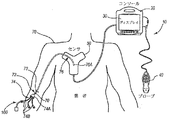
[00051]まず最初に図1および図2を参照して、本発明の例示的な一実施形態に従って構成された、全体として参照符号10で表示されている、カテーテル配置システム(「システム」)のさまざまなコンポーネントを示す。図示されているように、システム10は、一般に、コンソール20、ディスプレイ30、プローブ40、およびセンサ50を備え、これらのそれぞれは以下でさらに詳細に説明される。
[00051] Referring initially to FIGS. 1 and 2, a catheter placement system ("system"), generally designated by the
[00052]図2は、皮膚挿入部位73を通じて患者の血管系内にカテーテル72を配置する処置中の、患者70に対するこれらのコンポーネントの全体的な関係を示す。図2は、カテーテル72が、一般に、患者の外部に残る近位部74、および配置が完了した後に患者の血管系内に存在する遠位部76を含むことを示す。システム10は、患者の血管系内の所望の位置にカテーテル72の遠位先端76Aを最終的に位置決めするために利用される。一実施形態では、カテーテル遠位先端76Aの所望の位置は、上大静脈(「SVC」)の下3分の1(1/3)部分など、患者の心臓の近位である。もちろん、システム10は別の場所にカテーテル遠位先端を配置するために利用されてもよい。カテーテル近位部74は、カテーテル72の1つまたは複数の内腔の間に流体的連通をもたらすハブ74A、およびハブから近位方向に延在する1つまたは複数の延長脚74Bをさらに備える。
[00052] FIG. 2 shows the overall relationship of these components to the patient 70 during the procedure of placing the
[00053]コンソール20の実装例が図8Cに示されているが、コンソールは、さまざまな形態のうちの1つをとりうることは理解される。例えば、EEPROMなどの不揮発性メモリを備える、プロセッサ22は、システム10の動作中、システム機能を制御するために、コンソール20に含まれており、したがって制御プロセッサとして機能する。デジタルコントローラ/アナログインターフェース24は、コンソール20にも付属し、プローブ40、センサ50、および他のシステムコンポーネントの間のインターフェース動作を管理するために、プロセッサ22および他のシステムコンポーネントの両方と連通する。
[00053] Although an example implementation of
[00054]システム10は、センサ50、およびプリンタ、記憶媒体、キーボードなどを含むオプションコンポーネント54と接続するための、ポート52をさらに備える。一実施形態のポートは、USBポートであるが、このインターフェース接続および本明細書で説明されている他のインターフェース接続には、他のポートタイプまたはポートタイプの組合も使用されうる。外部電源58との動作可能な接続を可能にするため、電源接続部56がコンソール20に付属する。外部電源を使っても使わなくても、内部電池60も利用されうる。電力使用および分配を制御するために、パワーマネジメント回路59がコンソールのデジタルコントローラ/アナログインターフェース24に付属している。
[00054] The
[00055]本実施形態のディスプレイ30は、コンソール20と一体化されており、カテーテル配置処置中に臨床医に対して情報を表示するために使用される。別の実施形態では、ディスプレイはコンソールから分離されていてもよい。後でわかるように、ディスプレイ30によって示される内容は、カテーテル配置システムがUS、TLS、または別の実施形態ではECG先端確認のどのモードであるかに応じて変化する。一実施形態では、コンソールボタンインターフェース32(図1、図8C参照)およびプローブ40上に備えられているボタンが、配置処置を補助するために臨床医によってディスプレイ30に所望のモードを直ちに呼び出すために使用されうる。一実施形態では、TLSおよびECGなど、複数のモードからの情報は、図17に示されているように、同時に表示されてもよい。このように、システムコンソール20の単一のディスプレイ30は、患者の血管系内に入るための超音波誘導、カテーテルが血管系内を前進する間のTLS誘導、および(後述の実施形態に示すように)患者の心臓の結節に対するカテーテル遠位先端配置のECGに基づく確認に、利用されうる。一実施形態では、ディスプレイ30は、LCDデバイスである。
[00055] The
[00056]図3Aおよび図3Bは、一実施形態によるプローブ40の特徴を示す。プローブ40は、カテーテル72の血管系内への挿入に備えて、上述の第1のモダリティ、つまり、血管などの脈管の超音波(「US」)に基づく可視化に関連して採用される。このような可視化は、患者の血管系内にカテーテルを導入するためのリアルタイム超音波誘導機能を提供し、不注意による動脈穿刺、血腫、気胸などを含む、そのような導入に典型的に関連する合併症を減少させるのに役立つ。
[00056] FIGS. 3A and 3B illustrate features of the
[00057]手持ち式プローブ40は、予想される挿入部位73(図2)に近接する患者の皮膚に当たるようにヘッドが置かれたときに、超音波パルスを発生させ、患者の体による反射の後にそのエコーを受信するための、圧電アレイを収容するヘッド80を備える。プローブ40は、ボタンパッド82上に備えることができる、複数の制御ボタン84をさらに備える。本実施形態において、システム10のモダリティは、制御ボタン84によって制御することができ、したがって、コンソールボタンインターフェース32を使用してモードを変更するために、カテーテル配置に先立って患者の挿入部位の周辺に設けられた滅菌領域から、臨床医が手を伸ばす必要がなくなる。
[00057] The hand-held
[00058]そのようなものとして、一実施形態では、適切な挿入部位を判断して、針またはイントロデューサの後にカテーテルを使用するなどして血管系内にアクセスするために、臨床医は第1の(US)モダリティを用いる。次いで、臨床医は、滅菌領域の外へ手を伸ばす必要なく、プローブボタンパッド82上でのボタン押下によって、継ぎ目なく第2の(TLS)モダリティに切り替えることができる。次いで、TLSモードは、血管系内を目的の部位に向けてカテーテル72を前進させるのに役立てるために使用されうる。
[00058] As such, in one embodiment, a clinician first determines to determine the appropriate insertion site and access the vasculature, such as by using a catheter after a needle or introducer. (US) modality is used. The clinician can then seamlessly switch to the second (TLS) modality by pressing a button on the
[00059]図1は、プローブ40が、ボタンおよびプローブの動作を管理するためのボタンおよびメモリコントローラ42をさらに備えることを示す。一実施形態において、ボタンおよびメモリコントローラ42は、EEPROMなどの、不揮発性メモリを備えることができる。ボタンおよびメモリコントローラ42は、コンソール20のプローブインターフェース44と動作可能に連通し、プローブインターフェース44は、プローブ圧電アレイとインターフェースするための圧電入出力コンポーネント44A、ならびにボタンおよびメモリコントローラ42とインターフェースするためのボタンおよびメモリ入出力コンポーネント44Bを備える。
[00059] FIG. 1 shows that the
[00060]図4は、システム10が第1の超音波モダリティである間、ディスプレイ30に示されるような、例示的なスクリーンショット88を示す。患者70の皮下領域の画像90が示され、これは血管92の断面を示している。画像90は、プローブ40の圧電アレイが動作することで作成される。ディスプレイのスクリーンショット88にさらに含まれるのは、画像90の患者皮膚の下の深さに関する情報を提供する深度目盛りインジケータ94、標準カテーテル内腔サイズに対する血管92のサイズに関する情報を提供する内腔寸法目盛り96、および、例えば一時停止、画像テンプレート、データ保存、画像印刷、電源状態、画像明度など、システム10の状態または実行される可能性のある動作に関する情報を提供する、別の指標98である。
[00060] FIG. 4 shows an
[00061]血管が画像90に示されている間、他の実施形態では、別の体腔または部位を画像表示することができることに留意されたい。また、必要に応じて、図4に示されているUSモードを、TLSモードなどの他のモードと一緒に、ディスプレイ30に同時に示されうることにも留意されたい。画像ディスプレイ30に加えて、ブザー音、発信音などのような聴覚情報も、カテーテル配置中に臨床医を補助するために、システム10によって使用されうる。さらに、プローブ40およびコンソールボタンインターフェース32の上に備えられているボタンは、スライドスイッチ、トグルスイッチ、電子またはタッチセンサ式パッドなど、ボタンに加えてユーザー入力制御部を使用することを含めて、さまざまな方法で構成されうる。それに加えて、USおよびTLSの両方の活動が、システム10の使用中に、同時または排他的に発生しうる。
[00061] It should be noted that while a blood vessel is shown in the
[00062]上述のように、手持ち式超音波プローブ40は、カテーテルの経皮的導入に備えて、患者の末消血管系のUS可視化を可能にするために、統合型カテーテル配置システム10の一部として利用される。しかし、例示的な本実施形態では、以下で説明されるような血管系内の所望の目的部位に向けてカテーテルを誘導するときに、システム10のTLS部分、つまり第2のモダリティの機能を制御するためにも、プローブが使用される。ここでもまた、患者の滅菌領域内でプローブ40が使用されるので、この特徴は、完全に滅菌領域内からTLS機能を制御することを可能にする。このように、プローブ40は、滅菌領域からシステム10のUSおよびTLSの両方の機能の制御を都合よく可能にする2つの目的を有する装置である。一実施形態では、以下でさらに詳細に記述されているように、プローブは、カテーテル配置システム10の部分的または全部のECG関連機能、つまり第3のモダリティを制御するためにも使用されうる。
[00062] As noted above, the hand-held
[00063]カテーテル配置システム10は、上述の第2のモダリティ、つまり、磁気に基づくカテーテルTLS、または先端位置特定システムをさらに備える。TLSによって、臨床医は、患者70の血管系内への初期配置および前進の際に、末梢挿入中心静脈カテーテル(「PICC」)、中心静脈カテーテル(「CVC」)、または他の適切なカテーテルなどの、カテーテル72の位置および/または配向を、迅速に特定し、確認することができる。特に、TLSモダリティは、一実施例によればカテーテル72の縦方向に画定された内腔の内部に向けて予め実装されている、磁気要素搭載の先端位置特定スタイレットによって発生する磁場を検出し、これにより、臨床医は、患者の体内のカテーテル先端の全体的な位置および配向を確定することができる。一実施形態では、米国特許第5,775,322号、米国特許第5,879,297号、米国特許第6,129,668号、米国特許第6,216,028号、および米国特許第6,263,230号のうち1つまたは複数の教示を利用して、磁気アセンブリを追跡することができる。上述の米国特許の内容は、参照により本明細書に組み込まれている。TLSも、カテーテル先端が指している方向を表示し、そのため、正確なカテーテル配置にさらに役立つ。TLSは、所望の静脈経路から別の血管内に先端がずれてしまった場合など、カテーテル先端の位置異常が発生した場合を臨床医が判断するのにも役立つ。
[00063] The
[00064]上述のように、TLSは、血管系内での前進中にカテーテル72の遠位端を追跡できるようにするために、スタイレットを利用する。図5は、近位端100Aおよび遠位端100Bを含む、そのようなスタイレット100の一例を示す。ハンドルがスタイレットの近位端100Aのところに備えられ、そこから遠位方向に心線104が延在する。心線104の遠位には、磁気アセンブリが配置される。磁気アセンブリは、スタイレットの遠位端100Bの近位で相互に隣接して配置され、管108に封入された、1つまたは複数の磁気要素106を備える。一実施形態では、複数の磁気要素106が備えられ、各要素は他の磁気要素と末端同士で積層された、中実の円柱形の強磁性体を含む。接着先端110は、磁気要素106の遠位にある、管108の遠位先端を充填することができる。
[00064] As noted above, TLS utilizes a stylet to allow tracking of the distal end of
[00065]他の実施形態では、磁気要素は、形状だけでなく、組成、数、寸法、磁気の種類、およびスタイレットの遠位区画における位置に関して、設計と異なっていてもよいことに留意されたい。例えば、一実施形態では、複数の強磁性磁気要素の代わりに、センサによる検出のための磁場を発生させる、電磁コイルなどの、電磁アセンブリを使用する。本明細書で使用可能なアセンブリの別の例は、参照により本明細書に組み込まれている米国特許第5,099,845号、名称「Medical Instrument Location Means」にある。TLSモダリティとともに利用可能な磁気要素を含むスタイレットのさらに別の例は、参照により本明細書に組み込まれている2006年8月23日に出願した米国特許出願第11/466,602号、名称「Stylet Apparatuses and Methods of Manufacture」にある。したがって、これら、および他の変形形態は、本発明の実施形態によって企図される。本明細書で使用されているような「スタイレット」は、患者の血管系内の所望の部位にカテーテルの遠位端を配置するのに役立つ、カテーテルの内腔の内部へ取り外し可能に配置できるように構成された、さまざまなデバイスのいずれか1つを含むものとしてよいことは理解されるであろう。 [00065] It is noted that in other embodiments, the magnetic element may differ from the design in terms of composition, number, size, magnetic type, and position in the distal compartment of the stylet, as well as shape. I want. For example, in one embodiment, an electromagnetic assembly, such as an electromagnetic coil, that generates a magnetic field for detection by a sensor is used instead of a plurality of ferromagnetic magnetic elements. Another example of an assembly that can be used herein is in US Pat. No. 5,099,845, entitled “Medical Instrument Location Means”, which is incorporated herein by reference. Yet another example of a stylet that includes a magnetic element that can be used with a TLS modality is US patent application Ser. No. 11 / 466,602 filed Aug. 23, 2006, which is incorporated herein by reference. It is in “Style Apps and Methods of Manufacture”. Accordingly, these and other variations are contemplated by embodiments of the present invention. A “stylet” as used herein can be removably placed within the lumen of the catheter, which helps place the distal end of the catheter at a desired site within the patient's vasculature. It will be understood that any one of a variety of devices configured as such may be included.
[00066]図2は、その近位部が、カテーテル内腔からハブ74Aを通って延長脚74Bのうちの選択された1つから出るように近位に延在するように、カテーテル72の内腔の実質的内部のスタイレット100の配置を示す。カテーテルの内腔内にこのように配置されているため、スタイレット100の遠位端100Bは、スタイレットの遠位端のTLSによる検出がカテーテルの遠位端の位置をしかるべく示すように、カテーテル遠位端76Aと実質的に同じ位置に末端を有する。
[00066] FIG. 2 shows the interior of the
[00067]TLSセンサ50は、スタイレット100の磁気要素106によって発生する磁場を検出するためのTLS動作の際に、システム10によって使用される。図2に示されているように、TLSセンサ50は、カテーテル挿入中に、患者の胸部に配置される。患者の血管系を通じてカテーテルを通過させる間、上述のようにカテーテル72内に配置されたスタイレットの磁気要素106の磁場を検出できるようにするため、TLSセンサ50は、体の外部の目印を使用してなど、患者の胸部の所定の位置に配置される。ここでもまた、スタイレットの磁気アセンブリの磁気要素106がカテーテル72の遠位端76Aと実質的に同じ位置に末端を有するので(図2)、磁気要素の磁場のTLSセンサ50による検出は、その通過中にカテーテル遠位端の位置および方向に関して、臨床医に情報を提供する。
[00067] The
[00068]より詳細には、TLSセンサ50は、図1に示されているように、1つまたは複数のポート52を介して、システム10のコンソール20に動作可能に接続されている。TLSセンサとシステムコンソールとの間の他の接続スキームも限定されることなく使用可能であることに留意されたい。上記のように、患者の胸部に配置されたTLSセンサ50に関してカテーテル遠位端76A(図2)の位置を観察可能にするために、スタイレット100内において磁気要素106が利用される。スタイレットの磁気要素106のTLSセンサ50による検出は、TLSモードのときにコンソール20のディスプレイ30にグラフィックで表示される。このようにして、カテーテルを配置する臨床医は、TLSセンサ50に関する患者の血管系内のカテーテルの遠位端76Aの位置を一般的に判定することができ、望ましくない血管にそったカテーテルの前進など、カテーテルの位置異常が発生しつつあるときにそのことを検出することができる。
[00068] More specifically, the
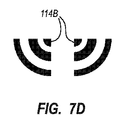
[00069]図6および図7A乃至図7Eは、TLSセンサ50によるスタイレットの磁気要素106の検出を示すために、コンソールディスプレイ30によって使用されうるアイコンの例を示す。特に、図6は、磁気要素がTLSセンサの下に位置しているときにTLSセンサ50によって検出されるような磁気要素106を含む、スタイレット100の遠位部を示すアイコン114を示す。スタイレットの遠位端100Bが、カテーテル72の遠位端76Aと実質的に同じ位置に末端を有するので、アイコンはカテーテルの遠位端の位置および配向を示す。図7Aから図7Eは、スタイレット100の磁気要素106がTLSセンサ50の一部分の直下に位置せず、しかし近辺に検出されるときにコンソールディスプレイ30に示される可能性のある、さまざまなアイコンを示す。アイコンは、TLSセンサ50に対するスタイレットの磁気アセンブリ、つまり、本実施形態では磁気要素106の位置に応じて表示される、1/2アイコン114Aおよび1/4アイコン114Bを含むことができる。
[00069] FIGS. 6 and 7A-7E illustrate examples of icons that may be used by the
[00070]図8A乃至図8Cは、TLSモードの間にシステム10のディスプレイ30から得られたスクリーンショットを示しており、これはスタイレット100の磁気アセンブリがどのように示されるかを示している。図8Aのスクリーンショット118は、TLSセンサ50の代表的な画像120を示す。深度目盛りインジケータ124、状態/動作指標126、およびコンソール20上に含まれるボタンインターフェース32に対応するアイコン128を含む、他の情報がディスプレイのスクリーンショット118上に提供される(図8C)。本実施形態のアイコン128は、ボタンインターフェース32の対応するボタンの目的を特定する際にユーザーを誘導するための単なるインジケータであるが、別の実施形態では、アイコン自体がボタンインターフェースとして機能することができ、システムのモードに応じて変化できるように、ディスプレイをタッチセンサ式にすることができる。
[00070] FIGS. 8A-8C show screenshots taken from the
[00071]挿入後の患者の血管内におけるカテーテルの前進の初期段階には、末端が実質的に同位置にあるスタイレットの遠位端100Bを有するカテーテル72の遠位端76Aは、TLSセンサ50から比較的離れている。そのようなものとして、ディスプレイのスクリーンショットは、スタイレットの磁気アセンブリからの磁場が検出されていないことを示す、「信号なし」を表示する。図8Bでは、スタイレットの遠位端100Bに近接する磁気アセンブリは、まだセンサの下にはないものの、それによって検出されるのに十分なほどTLSセンサ50の近くまで進んでいる。これは、センサ画像120の左にある1/2アイコン114Aによって示されており、スタイレットの磁気アセンブリが患者の視点からTLSセンサ50の右側に位置していることを表している。
[00071] In an early stage of catheter advancement within the patient's blood vessel after insertion, the
[00072]図8Cにおいて、スタイレットの遠位端100Bに近接する磁気アセンブリは、それに対応する自身の位置および配向がTLSセンサによって検出されるように、TLSセンサ50の下を前進してきている。これはセンサ画像120のアイコン114によって示されている。ボタンアイコン128が、コンソールボタンインターフェース32の対応するボタンを押下することによって実行可能な動作を示していることに留意されたい。そのようなものとして、ボタンアイコン128は、システム10がどのモダリティであるかに応じて変化することができ、したがってボタンインターフェース32が柔軟に使用できる。また、プローブ40のボタンパッド82(図3A、図3B)はボタンインターフェース32のボタンのいくつかを模倣したボタン84を含むので、ディスプレイ30上のボタンアイコン128は、滅菌領域にありながら、プローブボタン84によって臨床医がシステム10を制御するための誘導機能を提供することに留意されたい。例えば、臨床医がTLSモードを終了してUS(超音波)モードに戻る必要がある場合、プローブボタンパッド82の上にある適切な制御ボタン84が押下され、USモードが直ちに呼び出され、図4に示されるようなUS機能に必要な視覚情報に対応できるように、ディスプレイ30が更新されうる。これは、臨床医が滅菌領域の外へ手を伸ばす必要なく遂行される。
[00072] In FIG. 8C, the magnetic assembly proximate the stylet distal end 100B has been advanced under the
[00073]次に図9および図10を参照しつつ、別の例示的な実施形態による統合型カテーテル配置システム10を説明する。前と同様、統合システム10は、上述のように、コンソール20、ディスプレイ30、US機能のためのプローブ40、および先端位置特定機能のためのTLSセンサ50を備える。図9および図10に示されているシステム10は、多くの点で図1および図2に示されているシステムと類似していることに留意されたい。そのようなものとして、選択された違いのみが以下で説明される。図9および図10のシステム10は、患者70の洞房(「SA」)または心臓の他の電気的インパルス発生結節に関するカテーテル遠位先端76Aの接近の判断がなされうる付加的な機能を備え、それによって結節に近い所望の位置にカテーテル遠位先端を正確に配置する能力を高める。本明細書で「ECG」または「ECGに基づく先端確認」とも称される、システム10のこの第3のモダリティは、カテーテル遠位先端を患者の血管系内の所望の位置に配置するために、SA結節からのECG信号の検出を可能にする。US、TLS、およびECGモダリティは、本発明のシステム10の中に継ぎ目なく組み込まれ、協調してまたは個別に、カテーテル配置を補助するために利用することができることに留意されたい。
[00073] Referring now to FIGS. 9 and 10, an integrated
[00074]図9および図10は、本実施形態に基づいて構成されたスタイレット130のシステム10への追加を示す。概して、カテーテルスタイレット130は、挿入部位73を介して患者70の体内に挿入されるカテーテル72の内腔の中に取り外し可能に事前配置されている。スタイレット130は、磁気によるTLSモダリティのための磁気アセンブリを含むほかに、その遠位端に近接して、SA結節によって生成されるECG信号を検知するためのカテーテル先端の遠位端と同じ位置に末端を有する部分を含む、ECGセンサアセンブリも備える。前の実施形態とは対照的に、スタイレット130は、TLSセンサ50に動作可能に接続するその近位端から延在するテザー134を備える。後でさらに詳しく説明されるように、スタイレットのテザー134は、ECG信号による先端確認モダリティの一部としてのカテーテル先端位置の確認中に、スタイレット130の遠位部上に含まれるECGセンサアセンブリによって検出されるECG信号がTLSセンサ50に送られるようにする。基準および接地ECGリード/電極対158は、患者70の体に付着し、システムが心臓のSA結節の電気的活動と無関係の高レベル電気的活動を除去できるようにするために、TLSセンサ50に動作可能に取り付けられ、そうしてECGによる先端確認機能が可能になる。患者の皮膚上に配置されたECGリード/電極対158から受信された基準および接地信号とともに、スタイレットのECGセンサアセンブリによって検知されたECG信号も、患者の胸部に配置されたTLSセンサ50によって受信される(図10)。TLSセンサ50および/またはコンソールのプロセッサ22は、後述するように、ディスプレイ30上の心電図波形を生成するために、ECG信号データを処理することができる。TLSセンサ50がECG信号データを処理する場合、目的の機能を実行するために、プロセッサが中に備えられる。コンソール20がECG信号データを処理する場合、データを処理するために、プロセッサ22、コントローラ24、または他のプロセッサがコンソール内で使用されうる。
[00074] FIGS. 9 and 10 illustrate the addition to the
[00075]したがって、患者の血管系内を前進するにつれて、上述のようなスタイレット130を備えるカテーテル72は、図10に示すように患者の胸部に配置されたTLSセンサ50の下を前進することができる。これにより、TLSセンサ50は、患者の血管系内に位置するようなカテーテルの遠位先端76Aと実質的に同じ位置に末端を有する、スタイレット130の磁気アセンブリの位置を検出することが可能になる。スタイレットの磁気アセンブリのTLSセンサ50による検出は、ECGモードのときにディスプレイ30上に示される。ディスプレイ30は、ECGモードのときに、スタイレット130のECGセンサアセンブリによって検知されるような患者の心臓の電気的活動の結果として生成されたECG心電図波形を、さらに示す。より詳細には、SA結節のECG電気的活動は、P波の波形を含み、スタイレットのECGセンサアセンブリ(後述)によって検出され、TLSセンサ50およびコンソール20に送られる。次いで、ディスプレイ30上に表示するため、ECG電気的活動が処理される。次いで、カテーテルを配置する臨床医は、一実施形態におけるSA結節の近位など、カテーテル72の遠位先端76Aの最適な配置を決定するために、ECGデータを観察することができる。一実施形態では、コンソール20は、スタイレットのECGセンサアセンブリによって検出された信号を受信および処理するのに必要な、プロセッサ22(図9)などの電子部品を備える。別の実施形態では、TLSセンサ50は、ECG信号を処理する必須の電子部品を備えることができる。
[00075] Thus, as it advances through the patient's vasculature, the
[00076]すでに説明されているように、カテーテル配置処理中に臨床医に対して情報を表示するために、ディスプレイ30が使用される。ディスプレイ30の内容は、カテーテル配置システムがUS、TLS、またはECGのどのモードであるかに応じて変化する。3つのモードのうちいずれかが臨床医によってディスプレイ30上に直ちに呼び出され、場合によってはTLSとECGなど、複数のモードからの情報が同時に表示されうる。一実施形態では、前と同様に、システムのモードは手持ち式プローブ40に含まれる制御ボタン84によって制御され、これにより、モードを変更するために臨床医が滅菌領域の外へ手を伸ばす(コンソール20のボタンインターフェース32に触れるなど)必要がなくなる。こうして、本実施形態では、プローブ40は、システム10の一部または全部のECG関連機能を制御するためにも利用される。ボタンインターフェース32または他の入力構成も、システム機能を制御するために使用することができることに留意されたい。また、画像ディスプレイ30に加えて、ブザー音、発信音などのような聴覚情報も、カテーテル配置中に臨床医を補助するために、システムによって使用されうる。
[00076] As previously described, the
[00077]次に、図11乃至図12Eを参照しつつ、カテーテル72の中に取り外し可能に実装され、患者の血管系内の所望の位置にカテーテルの遠位先端76Aを位置決めするために挿入中に利用されるスタイレット130の一実施形態のさまざまな詳細を説明する。図示されているように、カテーテルから抜去されたスタイレット130は、近位端130Aおよび遠位端130Bを画定する。近位スタイレット端130Aにはコネクタ132が備えられ、テザー134はコネクタから遠位に延在してハンドル136に取り付けられる。心線138は、ハンドル136から遠位に延在する。スタイレット130は、遠位端130Bが遠位端76Aにあるカテーテル開口部と実質的に同一平面上にあるか、または同じ位置に末端を有するように(図10)、ならびに心線138の近位部、ハンドル136、およびテザー134が延長管74Bのうち選択された1つから近位に延在するように、一実施形態ではカテーテル72の内腔内に事前に実装されている。本明細書ではスタイレットと記載されているが、他の実施形態では、誘導線または他のカテーテル誘導装置が、本明細書で説明されている実施形態の原理を含むことが可能であることに留意されたい。
[00077] Referring now to FIGS. 11-12E, while being removably implemented within the
[00078]心線138は細長い形状を画定し、一実施形態では、ステンレス鋼、または一般に「ニチノール」という頭字語で知られているニッケルおよびチタン含有合金などの記憶材料を含む、適切なスタイレット材からなる。本明細書には示されていないが、一実施形態におけるニチノールからの心線138の製造では、カテーテル72の遠位部を類似の湾曲構成にするように、スタイレットの遠位区画に対応する心線の部分は事前整形された湾曲構成を有することが可能である。他の実施形態では、心線は事前整形を含まない。さらに、ニチノール構造は、心線138にトルク性を付与して、カテーテル72の内腔内に配置されながらスタイレット130の遠位区画を操作できるようにし、さらにカテーテル挿入中にカテーテルの遠位部が血管系内を誘導されるようにすることが可能である。
[00078] The
[00079]カテーテル72に対するスタイレットの挿入/抜去を可能にするため、ハンドル136が設けられている。スタイレットの心線138がトルクを有する実施形態において、このハンドル136は、心線がカテーテル72の内腔内で回転され、患者70の血管系内でカテーテル遠位部を誘導するのを補助することも可能にする。
[00079] A
[00080]ハンドル136は、テザー134の遠位端に取り付けられている。本実施形態では、テザー134は、上で参照されているECGセンサアセンブリとして働く心線138、およびテザーコネクタ132の両方に電気的に接続される1つまたは複数の導線を収容する柔軟な遮蔽ケーブルである。したがって、テザー134は、心線138の遠位部からスタイレット130の近位端130Aにあるテザーコネクタ132まで続く導電経路を形成する。後に説明されるように、テザーコネクタ132は、患者の血管系内の所望の位置までのカテーテル遠位先端76Aの誘導を補助するために、患者の胸部のTLSセンサ50に動作可能に接続するように構成される。
[00080] A
[00081]図12B乃至図12Dに示されているように、心線138の遠位部は、接合点142から遠位に段階的に細く、すなわち直径が小さくなっている。スリーブ140は、減径心線部の上を摺動する。ここでは直径が比較的大きめだが、別の実施形態のスリーブは、スタイレットの心線の近位部の直径と実質的に一致するサイズであってもよい。スタイレット130は、TLSモードの間に使用するその遠位端130Bの近位に配置された磁気アセンブリをさらに備える。図示されている実施形態の磁気アセンブリは、減径心線138の外面とスタイレット遠位端130Bの近位のスリーブ140の内面との間に介在する、複数の磁気要素144を備える。本実施形態では、磁気要素144は、図2のスタイレット100と類似の方法で末端同士で積層された、中実の円柱形の強磁性体を20個備える。しかし、他の実施形態では、磁気要素(複数可)は、形状だけでなく、組成、数、寸法、磁気の種類、およびスタイレットにおける位置に関して、設計とは異なっていてもよい。例えば、一実施形態では、磁気アセンブリの複数の磁石の代わりに、TLSセンサによる検出のための磁場を発生させる、1つの電磁コイルを使用する。したがって、これら、および他の変形形態は、本発明の実施形態によって企図される。
[00081] As shown in FIGS. 12B-12D, the distal portion of the
[00082]磁気素子144は、患者の胸部に配置されたTLSセンサ50に関してスタイレットの遠位端130Bの位置を観察可能にするために、スタイレット130の遠位部で利用される。すでに言及されているように、TLSセンサ50は、スタイレットが患者の血管内を通じてカテーテル72を前進させる際に、磁気要素144の磁場を検出するように構成されている。このようにして、カテーテル72を配置する臨床医は、患者の血管系内のカテーテル遠位端76Aの位置を一般的に判定することができ、例えば、望ましくない血管にそったカテーテルの前進など、カテーテルの位置異常が発生しつつあるときにそのことを検出することができる。
[00082] The
[00083]一実施形態によれば、スタイレット130は、前述のECGセンサアセンブリをさらに備える。ECGセンサアセンブリは、挿入中にカテーテル72の内腔内に配置されたスタイレット130が、患者の心臓のSAまたは他の結節によって発生した心房内ECG信号を検出するために利用できるようにし、それによってカテーテル72の遠位先端76Aを患者の心臓に近接する血管内の所定の位置まで誘導できるようにする。こうして、ECGセンサアセンブリは、カテーテル遠位先端76Aの適切な配置を確認するための補助としての役割を果たす。
[00083] According to one embodiment, the
[00084]図11乃至図12Eに図示されている実施形態において、ECGセンサアセンブリは、スタイレットの遠位端130Bの近位に配置された心線138の遠位部を含む。心線138は、導電性を有し、これにより、ECG信号は心線の遠位端によって検出され、心線にそって近位に送信されうる。導電性エポキシ樹脂などの導電体146は、心線の遠位端と導電的に連通するように、心線138の遠位終端に隣接したスリーブ140の遠位部を充填する。したがって、ECG信号を検出する能力を改善するように、スタイレット130の遠位端130Bの導電面が増大する。
[00084] In the embodiment illustrated in FIGS. 11-12E, the ECG sensor assembly includes a distal portion of a
[00085]カテーテル配置の前に、スタイレット130は、カテーテル72の内腔内に実装される。スタイレット130は、製造元からカテーテル内腔に事前実装された状態で納品されてもよく、あるいはカテーテル挿入に先立って臨床医によってカテーテル内に実装されてもよいことに留意されたい。スタイレット130は、スタイレット130の遠位端130Bがカテーテル72の遠位先端76Aと実質的に同じ位置に末端を有するように、カテーテル内腔に配置され、その結果スタイレットとカテーテルの両方の遠位先端を実質的に相互に位置を揃えて配置する。カテーテル72とスタイレット130が同じ位置に末端を有することにより、磁気アセンブリはTLSモードでTLSセンサ50とともに機能して、前述のように、患者の血管系内を前進する際に、カテーテル遠位先端76Aの位置を追跡することが可能となる。しかし、システム10の先端確認機能に関して、スタイレット130の遠位端130Bは、カテーテル遠位端76Aと同じ位置に末端を有する必要がないことに留意されたい。むしろ、要求されることは、患者の心臓のSA結節またはその他の結節の電気的インパルスが検出されることができるように、血管系とECGセンサアセンブリとの間の導電経路、この場合は心線138が確立されることだけである。一実施形態のこの導電経路は、食塩水、血液などをはじめとする、さまざまな要素を含むことができる。
[00085] Prior to catheter placement, the
[00086]一実施形態では、カテーテル72が挿入部位73を通じて患者の血管内に導入された後(図10)、カテーテル遠位先端76AをSA結節付近の目的の部位に向けて前進させるために、前に述べたように、システム10のTLSモードを利用することができる。心臓の領域に接近すると、システム10は、SA結節によって発信されるECG信号を検出できるようにするために、ECGモードに切り替えられうる。スタイレット実装カテーテルが患者の心臓に向かって前進すると、心線138の遠位端および導電体146を含む導電性ECGセンサアセンブリは、SA結節によって生成される電気的インパルスの検出を開始する。そのようなものとして、ECGセンサアセンブリは、ECG信号を検出するための電極としての役割を果たす。心線遠位端に近接する細長い心線138は、SA結節によって生成されECGセンサアセンブリによって受信される電気的インパルスをテザー134に伝達するための、導電経路としての役割を果たす。
[00086] In one embodiment, after the
[00087]テザー134は、一時的に患者の胸部に配置されたTLSセンサ50にECG信号を伝達する。テザー134は、テザーコネクタ132、または他の好適な直接もしくは間接接続構成を介して、TLSセンサ50に動作可能に接続される。次いで、前述のように、ECG信号は処理されて、システムディスプレイ30上に示される(図9、図10)。TLSセンサ50によって受信されディスプレイ30によって表示されるECG信号の監視によって、臨床医は、カテーテル遠位先端76AがSA結節に向かって前進する際の信号における変化を観察し、分析することが可能になる。受信されたECG信号が所望のプロファイルと一致したとき、臨床医は、カテーテル遠位先端76AがSA結節に関する所望の位置に到達したと判断することができる。前述のように、一実施形態では、この所望の位置は、SVCの下3分の1(1/3)部分の範囲内にある。
[00087] The
[00088]ECGセンサアセンブリおよび磁気アセンブリは、臨床医が血管系内にカテーテルを配置するのを補助するために協調して動作することができる。一般に、スタイレット130の磁気アセンブリは、患者の心臓の主な領域にカテーテル72の遠位端76Aを配置するように、一般的にカテーテルの初期挿入から血管系を誘導する際に、臨床医を補助する。次いで、ECGセンサアセンブリは、スタイレットのECGセンサアセンブリがSA結節に接近する際に心臓によって生成されるECG信号の変化を臨床医が観察できるようにすることで、カテーテル遠位端76AをSVC内の所望の位置に誘導するために利用することができる。ここでもまた、好適なECG信号プロファイルが観察されると、臨床医は、スタイレット130とカテーテル72との両方の遠位端が患者の心臓に対する所望の位置に到達したと判断することができる。望み通りに位置決めされた後、カテーテル72は、所定位置に固定されてもよく、またスタイレット130は、カテーテル内腔から抜去されてもよい。ここで、スタイレットは、本明細書内に明記されているものに加えて、さまざまな構成のうちの1つを含んでもよいことに留意されたい。一実施形態では、スタイレットは、TLSセンサを経由する間接取り付けの代わりに、コンソールに直接取り付けることができる。別の実施形態では、それのTLSおよびECG関連機能を可能にするスタイレット130の構造は、カテーテル構造自体に統合されてもよい。例えば、磁気アセンブリおよび/またはECGセンサアセンブリは、一実施形態では、カテーテルの壁部に組み込まれてもよい。
[00088] The ECG sensor assembly and the magnetic assembly can operate in concert to assist the clinician in placing the catheter within the vasculature. In general, the magnetic assembly of the
[00089]図13A乃至図15は、本実施形態による、スタイレットのテザー134から患者の胸部に配置されたTLSセンサ50へのECG信号データの経路に関するさまざまな詳細を示している。特に、この実施形態は、スタイレット130およびテザー134を含む、カテーテル72および挿入部位73を囲む滅菌領域、ならびにTLSセンサが位置する患者の胸部などの非滅菌領域からの、ECG信号データの経路に関する。このような経路は、その滅菌性が損なわれないように、滅菌領域を分断すべきではない。カテーテルの挿入処置中に患者70の上に位置する滅菌ドレープは、滅菌領域の大部分を画定し、ドレープの上の領域は滅菌されており、下の領域(挿入部位とすぐ周辺の領域を除く)は滅菌されていない。後でわかるように、以下の説明は、少なくともスタイレット130に関連する第1の連通ノード、およびTLSセンサ50に関連する第2の連通ノードを備え、これらは相互にECG信号データをやり取りできるようにするため動作可能に互いに接続している。
[00089] FIGS. 13A-15 illustrate various details regarding the path of ECG signal data from the
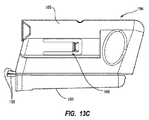
[00090]滅菌領域の滅菌性を損なわずに滅菌領域から非滅菌領域へのECG信号データ経路を扱う一実施形態は、「サメの鰭」実装とも呼ばれる「貫通ドレープ」実装を示す、図13A乃至図15に示されている。特に、図14Aは、カテーテル挿入処置中の患者の胸部に配置するための上述のようなTLSセンサ50を示す。TLSセンサ50はその上面に、3つの電気的ベースコンタクト154が配置されているチャネル152Aを画定するコネクタベース152を備える。図13A乃至図13Dにも示されるフィンコネクタ156は、図14Bおよび図15に示されているように、コネクタベース152のチャネル152Aによって摺動可能に受容される寸法を有している。2つのECGリード/電極対158は、肩、胴体、またはその他の好適な患者の体の外側の位置への配置のため、フィンコネクタ156から延在している。ドレープ穿刺テザーコネクタ132は、スタイレット120から滅菌領域を通ってTLSセンサ50までの導電経路を完成させるために、さらに以下で説明されるように、フィンコネクタ156の一部分と摺動的に結合するように構成されている。
[00090] One embodiment for handling an ECG signal data path from a sterile area to a non-sterile area without compromising the sterility of the sterile area shows a "penetrating drape" implementation, also referred to as a "shark shark" implementation, FIG. It is shown in FIG. In particular, FIG. 14A shows a
[00091]図13A乃至図13Dは、フィンコネクタ156のさらなる態様を示している。特に、フィンコネクタ156は、コネクタベース152のチャネル152Aに受容される寸法を有する下部バレル部160を画定する(図14B、図15)。中心錐体164によって囲まれた孔162は、上部バレル部166の後端上に含まれる。上部バレル部166は、テザーコネクタ132のチャネル172の内部に延在しているピンコンタクト170(図15)がフィンコネクタ156の孔162の中に着座するまで中心孔によって誘導され、これによりテザーコネクタをフィンコネクタと相互接続させるように、スタイレット130(図14C、図15)のテザーコネクタ132を受容する寸法を有している。図13Cおよび図13Dに示されている係合機能169などの係合機能は、2つの部品の結合の維持を補助するためにテザーコネクタ132の対応する機能と係合するために、フィンコネクタ156上に含まれるものとしてよい。
[00091] FIGS. 13A-13D illustrate additional aspects of the
[00092]図13Dは、フィンコネクタ156が複数の電気的コンタクト168を備えることを示している。本実施形態では、3つのコンタクト168が含まれ、最前の2つのコンタクトはそれぞれECGリード158のうちの1つの末端側終端と電気的に接続し、後部のコンタクトは、テザーコネクタ132がフィンコネクタ156と結合するときにテザーコネクタ132のピンコンタクト170と電気的に接続するように(図15)、孔162の軸近辺まで延在している。フィンコネクタ156のそれぞれのコンタクト168の底部は、TLSセンサのコネクタベース152のベースコンタクト154のうちの対応する1つと電気的に接続するように位置決めされる。
[00092] FIG. 13D shows that the
[00093]図14Bは、コネクタベースチャネル152Aとフィンコネクタの下部バレル部160との摺動的係合によってフィンコネクタ156がTLSセンサのコネクタベース152と取り外し可能に結合している、第1の接続段階を示す。この係合は、コネクタベースコンタクト154を、対応するフィンコネクタ168と電気的に接続させる。
[00093] FIG. 14B shows a first connection in which the
[00094]図14Cは、テザーコネクタチャネル172のフィンコネクタの上部バレル部166との摺動的係合によってテザーコネクタ132がフィンコネクタ156と取り外し可能に結合している、第2の接続段階を示す。この係合は、図15を見ると最もよくわかるように、テザーコネクタのピンコンタクト170を、フィンコネクタ156の後部コンタクト168と電気的に接続させる。本実施形態において、フィンコネクタ156に対するテザーコネクタ132の水平摺動は、フィンコネクタがセンサのコネクタベースチャネル152Aと摺動可能に嵌合しているとき(図14B)と同じ係合方向になっている。一実施形態において、スタイレット130/テザーコネクタ132およびフィンコネクタ156のうちの1つまたは両方が、使い捨てタイプである。また、一実施形態のテザーコネクタは、フィンコネクタがTLSセンサに嵌合された後でフィンコネクタに嵌合されることが可能だが、別の実施形態では、テザーコネクタは、フィンコネクタがTLSセンサに嵌合される前に、最初に外科用ドレープを通じてフィンコネクタと嵌合されることが可能である。
[00094] FIG. 14C illustrates a second connection stage in which the
[00095]図14Cに示される接続スキームでは、スタイレット130は、テザーコネクタ132を通じてTLSセンサ50に動作可能に接続され、それによってスタイレットのECGセンサアセンブリがTLSセンサにECG信号を伝達することが可能になる。それに加えて、ECGリード/電極対158は、TLSセンサ50に動作可能に接続される。したがって、一実施形態では、テザーコネクタ132は、スタイレット130の第1の連通ノードと称され、フィンコネクタ156は、TLSセンサ50の第2の連通ノードと称される。
[00095] In the connection scheme shown in FIG. 14C, the
[00096]スタイレットとTLSセンサとの間で動作可能な連通を確立するために、さまざまな他の接続スキームおよび構造を採用できることに留意されたい。例えば、ドレープを穿刺するために、テザーコネクタはピンコンタクトの代わりにスライスコンタクトを使用することができる。または、フィンコネクタは、TLSセンサと一体に形成されうる。したがって、これらの構成および他の構成は、本開示の実施形態の範囲内に包含される。 [00096] It should be noted that various other connection schemes and structures can be employed to establish operable communication between the stylet and the TLS sensor. For example, a tether connector can use a slice contact instead of a pin contact to puncture a drape. Alternatively, the fin connector can be formed integrally with the TLS sensor. Accordingly, these and other configurations are encompassed within the scope of the embodiments of the present disclosure.
[00097]図15に示されているように、滅菌領域を確立するためにカテーテル配置中に使用される滅菌ドレープ174は、テザーコネクタ132とフィンコネクタ156との相互接続の間に挟装される。上述のように、テザーコネクタ132は、2つのコンポーネントが嵌合しているときにドレープ174を穿刺するように構成されたピンコンタクト170を備える。この穿刺は、滅菌ドレープ174にピンコンタクト170で占有される小さな孔、または穿孔175を形成し、これによりピンコンタクトによるドレープ穿孔の大きさを最小限にする。さらに、テザーコネクタ132とフィンコネクタ156との間をぴったり合わせて、ピンコンタクト170を穿刺することによって設けられた滅菌ドレープの穿孔がテザーコネクタチャネル172によって囲まれ、それによりドレープの滅菌性を保持して、それによって確立された滅菌領域を損なう可能性のあるドレープの破損を防止するようにする。テザーコネクタチャネル172は、フィンコネクタ156の孔162の近位に配置されるまでピンコンタクトがドレープを穿刺しないように、ピンコンタクト170による穿刺前に滅菌ドレープ174を折り畳むように構成されている。ここで、テザーコネクタ132およびフィンコネクタ156は、不透明な滅菌ドレープ174を介しての目に見えない、つまり両コンポーネントの臨床医による視覚に頼らない触診を通じての、位置合わせを容易にするように構成されていることに留意されたい。
[00097] As shown in FIG. 15, a
[00098]図15に示されているようなフィンコネクタ156のフィンコンタクト168が、フィンコネクタをセンサベースチャネル152Aと係合した状態で保持するのに役立つような方法でセンサベースコンタクト154と結合するように構成されていることにさらに留意されたい。したがって、フィンコネクタ156をTLSセンサ50に固定するための追加装置の必要性が減じる。
[00098] The
[00099]図16は、P波およびQRS群を含む、代表的なECG波形176を示す。一般的に、P波の振幅は、波形176を発生させる、SA結節からのECGセンサアセンブリの距離に応じて変化する。カテーテル先端がいつ心臓付近に適切に配置されるかを判断するために、臨床医はこの関係を利用することができる。例えば、一実装では、すでに説明されているように、カテーテル先端は、望ましくは上大静脈の下3分の1(1/3)の範囲内に配置される。スタイレット130のECGセンサアセンブリによって検出されたECGデータは、ECGモードのときにシステム10のディスプレイ30上に表示するため、波形176などの波形を再生するのに使用される。
[00099] FIG. 16 shows a
[000100]次に、図17を参照しつつ、一実施形態により、システム10がECGモード、つまり、上で述べた第3のモダリティであるときの、ディスプレイ30上のECG信号データの表示態様を説明する。ディスプレイ30のスクリーンショット178は、TLSセンサ50の表示画像120を含む、TLSモダリティの要素を含み、また患者の血管系内を移動中のスタイレット130の遠位端の位置に対応するアイコン114も含みうる。スクリーンショット178は、スタイレット130のECGセンサアセンブリによって取得されシステム10によって処理される現在のECG波形が表示される、ウィンドウ180をさらに含む。ウィンドウ180は、新しい波形が検出されるときに継続的に更新される。
[000100] Referring now to FIG. 17, according to one embodiment, how the ECG signal data is displayed on the
[000101]ウィンドウ182は、最も新しく検出されたECG波形の連続表示を含み、また波形が検出されるとそれらを更新するために横方向に移動する、更新バー182Aを含む。ウィンドウ184Aは、臨床医が所望のカテーテル先端位置が達成されたときを判断するのを補助するための比較目的のため、ECGセンサアセンブリがSA結節に近づく前に取得された、基準ECG波形を表示するために使用される。ウィンドウ184Bおよび184Cは、ユーザーがプローブ40またはコンソールボタンインターフェース32の所定のボタンを押したときに、ユーザーによって選択された検出ECG波形別にファイリングできる。ウィンドウ184Bおよび184Cの波形は、ボタン押下または他の入力によるユーザーの選択の結果として、新しい波形によって上書きされるまで残る。前のモードと同様に、深度目盛り124、状態/動作指標126、およびボタンアイコン128が、ディスプレイ30上に表示される。ECGリード/電極対158がTLSセンサ50に動作可能に接続されているかいないかを指示するために、完全性インジケータ186もディスプレイ30上に表示される。
[000101]
[000102]したがって、上に示されているように、ディスプレイ30は、一実施形態において、単一の画面上でTLSおよびECGの両方のモダリティの要素を同時に示し、それにより臨床医はカテーテル遠位先端を所望の位置に配置するのを補助するための豊富なデータを利用できる。一実施形態では、適切なカテーテル配置を文書に記録できるように、スクリーンショットのプリントアウトまたは選択されたECGあるいはTLSデータが、システム10によって保存、印刷、または他の方法で保管されうることにさらに留意されたい。
[000102] Thus, as shown above, the
[000103]本明細書で説明されている実施形態は、PICCまたはCVCなどの、カテーテルの特定の構成に関係しているが、このような実施形態は単なる例にすぎない。したがって、本発明の原理は、多くの異なる構成および設計のカテーテルに拡大適用されうる。 [000103] Although the embodiments described herein relate to specific configurations of catheters, such as PICC or CVC, such embodiments are merely examples. Thus, the principles of the present invention can be extended to many different configurations and designs of catheters.
II.針/医療用コンポーネントの補助誘導
[000104]本明細書で説明されている本発明の実施形態は、一般に、例えば患者の皮下血管への針によるアクセスのため超音波に基づく、または他の好適な処置において針または他の医療用コンポーネントを配置し、誘導するための誘導システムを対象とする。一実施形態では、誘導システムにより、針の位置、配向、および前進を血管の超音波画像の上にリアルタイムで重ねて表示することができ、このため、臨床医は意図された標的まで針を正確に誘導することができる。さらに、一実施形態では、誘導システムは、x、y、およびz空間座標空間、針のピッチ、および針のヨーの5つの運動の自由度で針の位置を追跡する。そのような追跡により、針は比較的高い精度で誘導され、配置されうる。
II. Auxiliary guidance for needle / medical components
[000104] The embodiments of the invention described herein are generally based on ultrasound, eg, for needle access to the patient's subcutaneous blood vessels, or in other suitable procedures for needles or other medical applications. Intended for a guidance system for placing and guiding components. In one embodiment, the guidance system allows the needle position, orientation, and advancement to be displayed in real time superimposed on the ultrasound image of the blood vessel so that the clinician can accurately position the needle to the intended target. Can be guided to. Further, in one embodiment, the guidance system tracks the position of the needle in five degrees of freedom of movement in x, y, and z space coordinate space, needle pitch, and needle yaw. With such tracking, the needle can be guided and positioned with relatively high accuracy.
[000105]まず最初に図18および図19を参照して、本発明の一実施形態に従って構成された、全体として参照符号1110で指示されている、超音波に基づく針誘導システム(「システム」)のさまざまなコンポーネントを示す。図示されているように、システム1110は、一般に、コンソール1120、ディスプレイ1130、およびプローブ1140を備える超音波(「US」)撮像部を具備し、これらのそれぞれは以下でさらに詳細に説明される。システム1110は、一実施形態において、いくつかのコンポーネントに関して図1に示されているシステム10と類似していることに留意されたい。しかし、超音波撮像部は、本明細書で示され、説明されているものに加えて、さまざまな方法のうちの1つで構成されうることに留意されたい。
[000105] Referring first to FIGS. 18 and 19, an ultrasound-based needle guidance system ("system"), generally designated by
[000106]システム1110の超音波撮像部は、標的にアクセスするために針または他のデバイスを皮下挿入する前に患者の体内の標的とする部分を撮像するために使用される。以下で説明されているように、一実施形態では、針の挿入は、患者の静脈または血管系の他の部分をその後挿入する前に実行される。しかし、患者の体内への針の挿入は、さまざまな医療目的を伴って実行されうることは理解されるであろう。
[000106] The ultrasound imaging portion of the
[000107]図19は、一実施形態により、皮膚挿入部位1173を通じて患者の血管系内にカテーテル1172を最終的に配置する処置のときの、患者1170に対する上述のコンポーネントの全体的な関係を示す。図19は、カテーテル1172が、一般に、患者の外部に残る近位部1174、および配置が完了した後に患者の血管系内に存在する遠位部1176を含むことを示す。システム1110は、患者の血管系内の所望の位置にカテーテル1172の遠位先端1176Aを最終的に位置決めするために利用される。一実施形態では、カテーテル遠位先端1176Aの所望の位置は、上大静脈(「SVC」)の下3分の1(1/3)部分など、患者の心臓の近位である。もちろん、システム1110は別の場所にカテーテル遠位先端を配置するために利用されてもよい。
[000107] FIG. 19 illustrates the overall relationship of the above-described components to a
[000108]カテーテル近位部1174は、カテーテル1172の1つまたは複数の内腔の間に流体的連通をもたらすハブ1174A、およびハブから近位方向に延在する1つまたは複数の延長脚1174Bをさらに備える。述べたように、挿入部位1173において患者の血管系内に針を配置するのは、典型的には、カテーテルの挿入前に実行されるが、他の配置方法も使用されうることは理解されるであろう。さらに、上の説明は、システム1110を使用するための一例にすぎないことも理解され、実際、上記のようなカテーテルの挿入の準備としての針の配置、他に使用するための針の挿入、またはx線または超音波マーカ、生検シース、アブレーションコンポーネント、膀胱走査コンポーネント、大静脈フィルターなどを含む、患者の体内への他の医療用コンポーネントの挿入などのさまざまな使用目的に使用されうる。
[000108] The catheter
[000109]さらに詳しく言うと、コンソール1120は、システム1110のさまざまなコンポーネントを収納し、コンソールは、さまざまな形態のうちの1つをとりうることは理解される。例えば、EEPROMなどの不揮発性メモリを備える、プロセッサ1122は、システム1110の動作中、システム機能を制御し、さまざまなアルゴリズムを実行するために、コンソール1120に含まれており、したがって制御プロセッサとして機能する。デジタルコントローラ/アナログインターフェース1124は、コンソール1120にも付属し、プローブ1140、および他のシステムコンポーネントの間のインターフェース動作を管理するために、プロセッサ1122および他のシステムコンポーネントの両方と通信する。
[000109] More specifically, it is understood that the
[000110]システム1110は、プリンタ、記憶媒体、キーボードなどを含むオプションコンポーネント1154などの追加コンポーネントと接続するためのポート1152をさらに備える。一実施形態のポートは、USBポートであるが、このインターフェース接続および本明細書で説明されている他のインターフェース接続には、他のポートタイプまたはポートタイプの組合も使用されうる。外部電源1158との動作可能な接続を可能にするため、電源接続部1156がコンソール1120に付属する。外部電源を使っても使わなくても、内部電池1160も利用されうる。電力使用および分配を制御するために、パワーマネジメント回路1159がコンソールのデジタルコントローラ/アナログインターフェース1124に付属している。
[000110] The
[000111]本実施形態のディスプレイ1130は、コンソール1120と一体化されており、配置処置中に臨床医に対して、プローブ1140が達する標的とする体内部分の超音波画像などの情報を表示するために使用される。別の実施形態では、ディスプレイはコンソールから分離されていてもよい。一実施形態では、コンソールボタンインターフェース1132およびプローブ1140上に備えられている制御ボタン1184(図19)が、配置処置を補助するために臨床医によってディスプレイ1130に所望のモードを直ちに呼び出すために使用されうる。一実施形態では、ディスプレイ1130は、LCDデバイスである。
[000111] The
[000112]図19は、挿入部位1173を介して患者の血管系への初期アクセスを行うために使用される針1200をさらに示している。以下でさらに詳しく説明されるように、針1200は、システムが超音波に基づく配置処置中に針の位置、配向、および前進を検出することを可能にする際に、システム1110と連係動作するように構成されている。
[000112] FIG. 19 further illustrates a
[000113]図20は、一実施形態によるプローブ1140の特徴を示す。プローブ1140は、針1200および/またはカテーテル1172の血管系内への挿入に備えて、血管などの脈管の超音波に基づく可視化に関連して採用される。このような可視化は、リアルタイム超音波誘導機能を提供し、不注意による動脈穿刺、血腫、気胸などを含む、そのような導入に典型的に関連する合併症を減少させるのに役立つ。
[000113] FIG. 20 illustrates features of a
[000114]手持ち式プローブ1140は、予想される挿入部位1173(図19)に近接する患者の皮膚に当たるようにヘッドが置かれたときに、超音波パルスを発生させ、患者の体による反射の後にそのエコーを受信するための、圧電アレイを収容するヘッド1180を備える。システム1140は、システムを制御するために複数の制御ボタン1184(図19)をさらに備え、これにより、システム1110を制御するために、挿入部位の確定に先立って患者の挿入部位の周辺に設けられた滅菌領域から、臨床医が手を伸ばす必要がなくなる。
[000114] The hand-held
[000115]したがって、一実施形態では、臨床医は、血管系内を目的の部位に向けて最終的に前進させるためにカテーテル1172を導入する前に、好適な挿入部位を判断して、針1200を使用するなどして血管系内にアクセスするためにシステム1110の超音波撮像部を使用する。
[000115] Accordingly, in one embodiment, the clinician determines a suitable insertion site and introduces the
[000116]図18は、プローブ1140が、ボタンおよびプローブの動作を管理するためのボタンおよびメモリコントローラ1142をさらに備えることを示す。一実施形態において、ボタンおよびメモリコントローラ1142は、EEPROMなどの、不揮発性メモリを備えることができる。ボタンおよびメモリコントローラ1142は、コンソール1120のプローブインターフェース1144と動作可能に通信し、プローブインターフェース1144は、プローブ圧電アレイとインターフェースするための圧電入出力コンポーネント1144A、ならびにボタンおよびメモリコントローラ1142とインターフェースするためのボタンおよびメモリ入出力コンポーネント1144Bを備える。
[000116] FIG. 18 shows that the
[000117]図20に示されているように、プローブ1140は、上で説明されているような、超音波撮像処置中に針1200の位置、配向、および移動を検出するためのセンサアレイ1190を備える。以下でさらに詳しく説明されるように、センサアレイは、プローブのハウジング内に埋め込まれた複数の磁気センサ1192を備える。センサ1192は、針1200に関連する磁場を検出し、システム1110が針を追跡することを可能にするように構成される。ここでは磁気センサとして構成されているが、センサ1192は、以下で説明されるように、他の種類および構成のセンサであってもよい。また、図20にはプローブ1140に付属するように示されているが、センサアレイ1190のセンサ1192は、個別の手持ち式デバイスなどの、プローブから分離したコンポーネント内に収納できる。本実施形態では、センサ1192は、プローブ1140の上面1182の下に平面状構成で配置されているが、これらのセンサは、アーチ形または半円形の配置構成などの他の構成で配置されうることは理解される。
[000117] As shown in FIG. 20, the
[000118]本実施形態では、センサ1192のそれぞれは、3つの空間次元における磁場の検出を可能にするため3つの直交センサコイルを備える。このような3次元(「3D」)磁気センサは、例えば、Honeywell Sensing and Control社(ニュージャージー州モリスタウン所在)から購入することができる。さらに、本実施形態のセンサ1192は、ホール効果センサとして構成されているが、他の種類の磁気センサも使用することが可能である。さらに、1D、2D、または3D検出機能を実現するために、3Dセンサの代わりに、複数の1次元磁気センサが、必要に応じて備えられ、配置構成されうる。
[000118] In this embodiment, each of the
[000119]本実施形態では、5個のセンサ1192がセンサアレイ1190内に備えられ、これにより、針1200の検出が3つの空間次元(つまり、X、Y、Z座標空間)だけでなく、針それ自体のピッチおよびヨー配向でも可能になる。一実施形態では、センサ1192のうちの2つまたはそれ以上のセンサの直交検知コンポーネントにより、磁気要素1210、したがって針1200のピッチおよびヨー姿勢を判定することが可能になることに留意されたい。
[000119] In this embodiment, five
[000120]他の実施形態では、センサアレイで使用されうるセンサの数は加減できる。より一般的に、センサアレイの中のセンサの数、寸法、種類、および配置は、ここに明示的に示されているものと異なる場合があることは理解される。 [000120] In other embodiments, the number of sensors that can be used in the sensor array can be adjusted. More generally, it is understood that the number, size, type and arrangement of sensors in the sensor array may differ from those explicitly shown here.
[000121]図21Aおよび図21Bは、一実施形態により、図19に示されているように、患者の標的とする体内部分にアクセスする際に誘導システム1110に関連して使用されうる針1200の一例を詳細に示している。特に、針1200は、近位端1202Aおよび遠位端1202Bを画定する、中空カニューレ1202を備える。ハブ1204は、カニューレ1202の近位端1202Aに取り付けられ、本実施形態において、さまざまなデバイスと接続するためのコネクタとして構成された開放端1204を備える。実際、ハブ1204の開放端1204Aは、誘導線、スタイレット、または他のコンポーネントがハブを通してカニューレ内に入るように中空カニューレ1202と連通している。
[000121] FIGS. 21A and 21B illustrate a
[000122]図21Aおよび図21Bに示されているように、磁気要素1210は、ハブ1204に付属する。図21Bから最もよくわかるように、本実施形態における磁気要素1210は、例えば、強磁性体を含む、永久磁石であり、また中空カニューレ1202と位置を揃えた孔1212を画定するようにリング形状をとる。こうして構成された磁気要素1210は、以下でさらに詳しく説明されているように、針1200の位置、配向、および移動がシステム1110によって追跡できるように、超音波プローブ1140のセンサアレイ1190によって検出可能である磁場を発生する。
[000122] As shown in FIGS. 21A and 21B, a
[000123]他の実施形態では、多くの他の種類、数、および寸法の磁気要素が、針1200または他の医療用コンポーネントとともに使用され、本発明の誘導システムによるその追跡が可能になるものとしてよいことは理解される。
[000123] In other embodiments, many other types, numbers, and dimensions of magnetic elements are used in conjunction with the
[000124]次に、患者の皮膚表面1220を通して挿入し体内の標的部分にアクセスする準備が整っている、適所にあるシステム1110および針1200の超音波プローブ1140を示す図22Aおよび図22Bを参照する。特に、患者の皮膚表面1220の下の血管1226の一部を超音波撮像するためにヘッド1180を患者の皮膚にあてがい、超音波ビーム1222を発生する、プローブ1140が図示されている。血管1226の超音波画像は、システム1110のディスプレイ1130上に示されうる(図19)。
[000124] Reference is now made to FIGS. 22A and 22B showing the
[000125]上で述べたように、本実施形態におけるシステム1110は、上述の針1200の位置、配向、および移動を検出するように構成されている。特に、プローブ1140のセンサアレイ1190は、針1200に付属する磁気要素1210の磁場を検出するように構成される。センサアレイ1190のセンサ1192のそれぞれは、3次元空間内で磁気要素1210を空間的に検出するように構成される。したがって、システム1110の動作中、センサ1192のそれぞれによって検知される針の磁気要素1210の磁場強度データが、磁気要素1210の位置および/または配向をリアルタイムで計算する、コンソール1120(図18)のプロセッサ1122などのプロセッサに転送される。
[000125] As noted above, the
[000126]特に、また図22Aおよび図22Bに示されているように、センサアレイ1192に関するX、Y、およびZ座標空間内の磁気要素1210の位置は、センサ1192によって検知された磁場強度データを使用してシステム1110によって判定されうる。さらに、図22Aは、磁気要素1210のピッチも判定されうることを示しており、図22Bは、磁気要素のヨーが判定されうることを示している。システムのプローブ1140、コンソール1120、または他のコンポーネントの好適な回路は、そのような位置/配向に必要な計算を行うことができる。一実施形態では、米国特許第5,775,322号、米国特許第5,879,297号、米国特許第6,129,668号、米国特許第6,216,028号、および米国特許第6,263,230号のうち1つまたは複数の教示を利用して、磁気要素210を追跡することができる。上述の米国特許の内容は、参照により本明細書に組み込まれている。
[000126] In particular, and as shown in FIGS. 22A and 22B, the position of the
[000127]システムによって認識されるか、またはシステムに入力されるような遠位針先端に関するカニューレ1202の長さおよび磁気要素1210の位置とともに、システム1110によって決定される上記の位置および配向情報を利用することで、システムは、センサアレイ1190に関する針1200の全長の配置および配向を正確に決定することができる。適宜、磁気要素1210と遠位針先端との間の距離は、システム1110によって認識されるか、またはシステム1110に入力される。次いで、これにより、システム1110は、針1200の画像をプローブ1140の超音波ビーム1222によって生成される画像上に重ねて表示することができる。図23Aおよび図23Bは、超音波画像上への針のこのような重ね合わせ表示の例を示している。特に、図23Aおよび図23Bは、それぞれ、例えば、ディスプレイ1130(図19)上に示されうるスクリーンショット1230を示している。図23Aには、超音波1232が示されており、これは患者の皮膚表面1220、および皮下血管1226の表示を含む。超音波画像1232は、例えば図22Aおよび図22Bに示されている超音波ビーム1222によって撮像される像に対応する。
[000127] Utilizing the above position and orientation information determined by the
[000128]スクリーンショット1230は、上で説明されているようなシステム1110によって決定された実際の針1200の位置および配向を表す針の画像1234をさらに示す。システムは、センサアレイ1190に関して針1200の配置および配向を決定することができるので、システムは、超音波画像1232に関して針1200の位置および配向を正確に決定し、それを上に重ね合わせて、ディスプレイ1130上に針の画像1234として示すことができる。超音波画像1232上の針の画像1234の位置決めの調整は、プロセッサ1122またはシステム1110の他の好適なコンポーネントによって実行される好適なアルゴリズムによって実施される。
[000128] Screen shot 1230 further shows a
[000129]センサ1192は、システム1110の動作中に針1200の磁気要素1210の磁場を連続的に検出するように構成される。これにより、システム1110は、ディスプレイ1130上に示すために針の画像1234の位置および配向を連続的に更新することができる。そこで、針1200の前進または他の移動は、ディスプレイ1130上の針の画像1234によってリアルタイムで示される。システム1110は、プローブ1140および針1200の移動が配置処置または他の活動の最中に生じるときに超音波画像1232と針の画像1234との両方を連続的に更新することができることに留意されたい。
[000129]
[000130]図23Aは、一実施形態において、システム1110が針の画像1234によって示されているような針1200の現在の位置および配向に基づき投影された経路1236を示しうることをさらに示している。投影された経路1236は、ディスプレイ1130上に針の画像1234によって示されるような、針1200の現在の配向の結果、ここで示されている血管1226などの、所望の体内部分の標的に達するかどうかを臨床医が判定するのを補助する手段となる。ここでもまた、針の画像1234の配向および/または位置が変化すると、投影された経路1236は、それに応じて、システム1110によって修正される。投影された経路1236が超音波画像1232の平面と交差する点を示す、標的1238も、システム1110によってディスプレイ1130に表示されうる。図23Aに示されているように、本例では、標的1238は、超音波画像1232に示される血管1226内に配置される。ディスプレイ1130上の標的1238の位置も、針1200および/または超音波画像1232が調整されるときに修正されうることに留意されたい。スクリーンショット1230は、ここではボックスとして示されている、確率の領域1239も含み、これは針の長さ、針の剛性および柔軟性、磁気要素の磁場強度、磁気干渉、磁気要素の磁気軸と針の縦軸との位置合わせの可能な食い違い、超音波撮像平面に関するセンサアレイの配向などによるシステムの可能な誤差の範囲を示す。
[000130] FIG. 23A further illustrates that in one embodiment, the
[000131]図23Bは、超音波画像1232および針の画像1234が3次元の態様で表示される配向となるように構成されうることを示している。これにより、針の画像1234によって示されているように、針1200の角度および配向を確認し、超音波画像1232によって撮像される意図された標的と比較することができる。スクリーンショット1230は、表示用にシステム1110によって生成される可能な指示の例にすぎないことに留意すべきであり、実際、他の視覚的指示も使用することができる。撮像される身体の特定の領域も一例にすぎないことにさらに留意すべきであり、システムは、さまざまな身体部分を超音波で撮像するために使用することができ、添付図面に明示的に示されているものに限定されるべきでない。さらに、本明細書で図示され、説明されているようなシステムは、必要ならばより大きなシステムのコンポーネントとして備えられうるか、またはスタンドアロンのデバイスとして構成されうる。また、画像ディスプレイ1130に加えて、ブザー音、発信音などのような聴覚情報も、針を患者体内に位置決めし挿入しているときに臨床医を補助するために、システム1110によって使用されることもできることは理解される。
[000131] FIG. 23B shows that the
[000132]上述のように、一実施形態では、システム1110が針1200の全長およびその上の磁気要素1210の配置を認識し、針の画像1234ならびに図23Aおよび図23Bのスクリーンショット1230の他の特徴を正確に示すことができるようにする必要がある。システム1110に対して、針に付けられているか、または針に伴うバーコードのシステムによる走査、システムによる走査のために無線ICタグ(「RFID」)チップを針とともに組み込むこと、針のカラーコーディング、臨床医がパラメータを手動でシステムに入力することなどを含む、さまざまな方法でこれらおよび/または他の関連するパラメータを通知することができる。例えば、RFIDチップ1354は、図33Aに示されている針1200上に備えられる。システム1110のプローブ1140または他のコンポーネントは、RFIDリーダーを備えることができ、これにより、針1200の種類または長さなどの、RFIDチップ1354に入っている情報を読み取ることができる。したがって、針のパラメータをシステム1110に入力するか、またはパラメータを検出するためのこれらの手段および他の手段が企図されている。
[000132] As described above, in one embodiment, the
[000133]一実施形態では、針の長さ(または医療用コンポーネントの他の態様)は、その磁場強度などの、磁気要素の特性のプローブ/システムによる測定によって決定されうる。例えば、一実施形態では、針の磁気要素は、プローブから所定の距離のところに、またはプローブに関して所定の配置で位置決めされうる。磁気要素がそのように位置決めされると、プローブのセンサアレイは、磁気要素の磁場強度を検出し、測定する。システムは、測定された磁場強度を針の異なる長さに対応する可能な磁場強度の格納されているリストと比較することができる。システムは、これら2つの強度を照合して、針の長さを決定することができる。次いで、針の配置およびその後の針の挿入は、本明細書で説明されているように進行することができる。別の実施形態では、磁気要素を所定の場所に固定して保持する代わりに、磁場強度の複数の読み取りがプローブによって行われるように磁気要素がプローブの周りを移動されうる。異なる磁場強度を一連の磁気要素に付与するように修正されうる態様は、磁気要素の寸法、形状、および組成を含む。 [000133] In one embodiment, the length of the needle (or other aspect of the medical component) can be determined by measurement by a probe / system of a property of the magnetic element, such as its magnetic field strength. For example, in one embodiment, the magnetic element of the needle may be positioned at a predetermined distance from the probe or in a predetermined arrangement with respect to the probe. When the magnetic element is so positioned, the sensor array of the probe detects and measures the magnetic field strength of the magnetic element. The system can compare the measured magnetic field strength to a stored list of possible magnetic field strengths corresponding to different needle lengths. The system can match these two intensities to determine the needle length. The needle placement and subsequent needle insertion can then proceed as described herein. In another embodiment, instead of holding the magnetic element fixed in place, the magnetic element can be moved around the probe such that multiple readings of the magnetic field strength are taken by the probe. Embodiments that can be modified to impart different magnetic field strengths to a series of magnetic elements include the size, shape, and composition of the magnetic elements.
[000134]一実施形態による、患者の標的とする体内部分(「標的」)の超音波撮像に関連して針もしくは他の医療用デバイスを誘導する際にシステム1110を使用することについてさらに詳しく述べる。磁気要素を装着した針1200がセンサアレイ1190を含む超音波プローブ1140から好適な距離(例えば、61cm(2フィート)以上)だけ離れたところに位置決めされた場合、システム1110のディスプレイ1130に示すことを目的として、経皮的刺入を介して針が交差することが意図されている患者体内の標的を超音波で撮像するためにプローブが使用される。次いで、システム1110のキャリブレーションが開始され、その際に、コンソール1120のプロセッサ1122によって、処置が実行される場所の近くで周囲磁場に対するベースラインを決定するアルゴリズムが実行される。システム1110は、上で説明されているように、針1200の全長、および/またはユーザー入力、自動検出、もしくは別の好適な方法などによる遠位針先端に関する磁気要素の位置の通知も受ける。
[000134] Further details of using the
[000135]次いで、プローブ1140のセンサアレイ1190のセンサ1192の範囲内に針1200が移動される。センサ1192のそれぞれは、針1200の磁気要素1210に関連する磁場強度を検出し、このデータはプロセッサ1122に転送される。一実施形態では、そのようなデータは、プロセッサに必要になるまでの間メモリに格納しておくことができる。センサ1192が磁場を検出すると、プローブと関係する空間内の予測される点で針1200の磁気要素1210の磁場強度を計算するために、好適なアルゴリズムがプロセッサ1122によって実行される。次いで、プロセッサ1122は、センサ1192によって検出された実際の磁場強度データを計算された磁場強度値と比較する。このプロセスは、上に示されている米国特許によってさらに説明されていることに留意されたい。このプロセスは、予測される点に対する計算値が測定データと一致するまで繰り返し実行されうる。この一致が生じた後、磁気要素1210は、3次元空間内に位置決めされ配置されている。センサ1192によって検出された磁場強度データを使用して、磁気要素1210のピッチおよびヨー(つまり、配向)も決定されうる。針1200の知られている長さおよび磁気要素に関する針の遠位先端の位置と合わせて、これにより、針の位置および配向の正確な表現が可能になり、またこれは、システム1110によって行うことができ、ディスプレイ1130上に仮想モデル、つまり、針の画像1234として示すことができる。予測値および実際の検出値は、針の表示を行えるようにシステム1110に対する一実施形態の所定の許容差または信頼水準の範囲内で一致しなければならないことに留意されたい。
[000135] The
[000136]上述のような針1200の仮想的な針の画像1234の表示は、ディスプレイ1130の超音波画像1232上に針の画像を重ねることによって本実施形態において実行される(図23A、図23B)。プロセッサ1122または他の好適なコンポーネントによって実行されるようなシステム1110の好適なアルゴリズムにより、投影された経路1236、標的1238、および確率の領域1239(図23A、図23B)を決定し、ディスプレイ1130上で標的の超音波画像1232の上に表示することができる。針1200の移動をリアルタイムで追跡し続けるために、上記の予測、検出、比較、および表示プロセスが繰り返し実行される。
[000136] The display of the
[000137]前記に照らし、図24を参照すると、一実施形態において針または他の医療用コンポーネントを誘導するための方法1240は、さまざまな段階を含むことが理解される。段階1242で、患者の標的とする体内部分が、例えば超音波撮像デバイスなどの、撮像システムによって撮像される。
[000137] In light of the foregoing, and with reference to FIG. 24, it is understood that in one embodiment a
[000138]段階1244で、針などの医療用コンポーネントの検出可能な特性は、撮像システムに付属する1つまたは複数のセンサによって検知される。本実施形態では、針の検出可能な特性は、針1200に付属する磁気要素1210の磁場であり、センサは、超音波プローブ1140に付属するセンサアレイ1190に備えられている磁気センサである。
[000138] At
[000139]段階1246で、標的とする体内部分に関する医療用コンポーネントの位置は、検出可能な特性の検知を介して少なくとも2つの空間次元内で判定される。上で説明されているように、コンソール1120のプロセッサ1122によって本実施形態においてそのような判定が行われる。
[000139] At
[000140]段階1248で、医療用コンポーネントの位置を表す画像は、ディスプレイ上に示す標的とする体内部分の画像と組み合わされる。段階1250は、例えば、血管1226(図23A、図23B)への針1200の皮下刺入など、撮像された標的に関する医療用コンポーネントの前進もしくは他の移動を示すために段階1244乃至段落1248が反復的に繰り返されうることを示している。
[000140] At
[000141]プロセッサ1122または他の好適なコンポーネントは、ディスプレイ1130に示すために確率の領域1239および標的1238(図23A、図23B)を含む、追加の態様を計算することができることは理解される。
[000141] It will be appreciated that the
[000142]一実施形態では、センサアレイは、超音波撮像デバイス内に固有のものとして組み込まれる必要はないが、他の方法でそれに付属するものであってよいことは理解される。図25はこれの一例を示しており、そこでは、センサアレイ1190のセンサ1192を含む取り付け可能なセンサモジュール1260が超音波プローブ1140に取り付けられているように示されている。そのような構成により、本明細書で説明されているような針の誘導は、標準の超音波撮像デバイス、つまり、超音波プローブ内に一体化されたセンサアレイまたは上述のように針を配置し、追跡するように構成されたプロセッサおよびアルゴリズムを備えていないデバイスに関連して達成されうる。したがって、一実施形態のセンサモジュール1260は、針もしくは他の医療用コンポーネントを配置し、追跡するのに適した、また超音波画像の上に重ねるために針の仮想的画像をディスプレイ上に表示するのに適したプロセッサおよびアルゴリズムを備える。一実施形態では、センサモジュール1260は、針の追跡を示すためにモジュールディスプレイ1262に付属するものとしてよい。したがって、誘導システムのこれらの構成および他の構成が企図される。
[000142] In one embodiment, it is understood that the sensor array need not be uniquely incorporated into the ultrasound imaging device, but may be otherwise attached to it. FIG. 25 shows an example of this, where an
[000143]図26は、すでに説明されているようにシステム1110によって実行される音波撮像および針誘導処置の間に針1200を保持し、前進させるためにニードルホルダが使用されうることを示している。図示されているように、ニードルホルダ1270は、ピストル形をしており、トリガーを押した後にホルダのバレルから縦方向に針を遠ざけることによって針1200または他の好適な医療用コンポーネントを選択的に前進させるためのトリガー1272を備える。こうして構成されているため、ニードルホルダ1270を使用することで、臨床医は片方の手で針を扱い、もう片方の手で超音波プローブ1140を掴んで操作することを容易に行える。それに加えて、ニードルホルダ1270は、モーター、ラッチ機構、油圧/空気圧駆動装置などを介して、針の移動/回転を補助することができる。さらに、ニードルホルダ1270にクロッキング機能を備えることで、針1200の遠位先端の配向を判定することを補助し、針の回転を円滑にすることができる。
[000143] FIG. 26 illustrates that the needle holder can be used to hold and advance the
[000144]一実施形態では、ニードルホルダ1270は、針カニューレ1202の遠位端1202Bが標的とする体内部分に到達するか、または針が超音波平面を遮ったときにニードルホルダによる前進が自動的に停止するようにシステム1110に動作可能に接続されうる。さらに別の実施形態では、磁気要素は、針それ自体の代わりに、ニードルホルダに付属するものとしてよい。したがって、針は、ニードルホルダに一時的に取り付けられたときに、磁気要素を針に直接取り付けることなく誘導システムによって配置され、誘導されうる。
[000144] In one embodiment, the
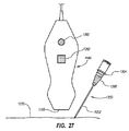
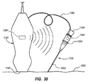
[000145]図27Aおよび図28は、別の実施形態による誘導システム1110のコンポーネントを示しており、そこでは、針の追跡および誘導を可能にするためにプローブ1140と針1200との間の光学的な相互作用が使用される。特に、プローブ1140は、LED1280などの光学系/光源、およびプローブ表面に位置決めされた光検出器1282を備える。光源および検出器は、可視光線、赤外線などを含むさまざまな範囲の光信号を発生し、検出するように構成されうることは理解される。
[000145] FIGS. 27A and 28 show components of a
[000146]針のハブ1204は、LED 1280が発生する光およびそこへの入射光を反射することができる反射面1286を備える。図28に示されているように、LED 1280によって放射される光は、針1200の反射面1286によって反射され、その一部は、光検出器1282によって受信され、検知される。前の実施形態と同様に、光検出器1282の検知データを受信し、針1200の位置および/または配向を計算するために、システムコンソール1120のプロセッサ1122が使用されうる。前述のように、針1200の長さおよび/または針1200の遠位端に関する反射面の位置は、システム1110に入力されるか、または他の方法で検出可能であるか、または認識される。反射面は、針の他の場所に含まれていてもよいことに留意されたい。
[000146] The
[000147]上記に照らして、本実施形態において、針1200の検出可能な特性は、前の実施形態の磁気要素1210の磁場特性とは対照的に反射面1286の反射性を含み、センサは、前の実施形態の磁気センサ1192とは対照的に、光検出器1282を備える。一実施形態では、上で説明されている構成は反転させることができ、その場合、光源は針もしくは医療用コンポーネントに付属することは理解されるであろう。この場合、光は針から放射され、プローブ1140に付属する光検出器1282によって検出され、これにより、針の配置および追跡が可能になる。針の光源に電力を供給するために、時計用電池または同様のものなどの電源が、針に付属してもよい。
[000147] In light of the above, in this embodiment, the detectable characteristic of the
[000148]より一般的に、針もしくは医療用コンポーネントは、患者の体内の標的に向けて針を追跡し、誘導することが可能になるようにこれら、または他の検出可能な特性のうちの1つまたは複数の特性を含みうることは理解される。他の検出可能な特性モダリティの非限定的な例として、電磁気または高周波(「RF」)(例えば、以下の図29乃至図30を参照)、ならびに放射線が挙げられる。RFモダリティに関して、1つまたは複数の同期もしくは非同期パルス周波数源が針に付属するようにし、好適なセンサ(複数可)によるその検出を可能にすることができることは理解される。または、第1のRF源は、第2の供給源としての受動磁石と結合されうる。 [000148] More generally, the needle or medical component is one of these or other detectable properties so that the needle can be tracked and guided toward a target in the patient's body. It is understood that one or more characteristics can be included. Non-limiting examples of other detectable characteristic modalities include electromagnetic or radio frequency (“RF”) (see, eg, FIGS. 29-30 below), and radiation. With respect to the RF modality, it is understood that one or more synchronous or asynchronous pulse frequency sources can be attached to the needle and allow its detection by suitable sensor (s). Alternatively, the first RF source can be coupled with a passive magnet as a second source.
[000149]図29および図30は、一実施形態による誘導システムのコンポーネントを示しており、そこでは、針の追跡および誘導を可能にするためにプローブ1140と針1200との間のEM信号の相互作用が使用される。特に、図29では、針1200は、中に配置されているスタイレット1298を備える。スタイレット1298は、テザー1292を介してプローブ1140に動作可能に接続されているEMコイル1290を備える。このようにして、EMコイル1290は、動作中にEMコイルがEM信号を放射するようにプローブ1140またはシステムコンソール1120内に備えられている好適なコンポーネントによって駆動されうる。
[000149] FIGS. 29 and 30 illustrate components of a guidance system according to one embodiment, in which EM signals between the
[000150]スタイレット1298のEMコイル1290によって放射されるEM信号を検出するのに適したセンサ1294は、プローブ1140内に備えられる。本実施形態では、センサ1294は、EM信号の対応する直交成分を検出する3軸センサであるが、他のコイルおよびセンサ構成も使用できる。こうして構成されているため、針1200の位置および配向は、EM信号の三角測量または他の好適なプロセスによって判定され、上ですでに説明されているのと類似の方法でシステムによって表示されうる。前の実施形態と同様に、EMセンサ1294の検知データを受信し、針1200の位置および/または配向を計算するために、システムコンソール1120(図18)のプロセッサ1122が使用されうる。前述のように、針1200の長さおよび/または針1200の遠位端に関するEMコイル1290の位置は、システムに入力されるか、または他の方法で検出可能であるか、または認識される。
[000150] A
[000151]図30は、図29のEM構成の変更形態を示しており、そこでは、EMコンポーネントの各位置が逆転され、EMコイル1290は、プローブ1140内に備えられ、EMセンサ1294は、針1200内に配置されているスタイレット1298に付属する。図29および図30の実施形態では、テザー1292を介したEMコイル1290とEMセンサ1294との間の動作可能な接続により、スタイレット1298内に配置されているコンポーネントはシステム1110によって駆動されうることに留意されたい。また、これにより、特定のEM周波数/EMコイル1290によって放射され、EMセンサ1294によって検出された周波数を対応付けることも可能である。一実施形態では、図29に示されている構成を変えることができ、その場合、テザーはEMコイルとEMセンサとを動作可能に接続せず、むしろ、スタイレットのEMコイルは、プローブおよびそのEMセンサとは別のコンポーネントとして動作し、電池などの独立した電源によって給電される。この場合、プローブ/システムは、EMコイルによって放射されたEM信号を検出し、それを、針を配置するために必要なものとして処理するように構成された好適な信号処理コンポーネントを備える。
[000151] FIG. 30 shows a variation of the EM configuration of FIG. 29, where each position of the EM component is reversed, an
[000152]EMコイルおよびEMセンサは、ここに示されているものと異なる場所に備えられうることに留意されたい。例えば、EMコイルは、針それ自体に、または針の近位端に取り付け可能であるコネクタ上に備えることができる。 [000152] Note that the EM coil and EM sensor may be provided in different locations than those shown here. For example, the EM coil can be provided on the needle itself or on a connector that can be attached to the proximal end of the needle.
[000153]図31A乃至図31Dは、一実施形態により構成された針1200のさらなる詳細を示しており、そこでは、針はハブ1304を備え、カニューレ1202はそこから延在する。孔1312を画定する磁気要素1310は、ハウジング1314の空洞1314A内に備えられる。ハウジング1314は、針のハブ1304、または針もしくは医療用コンポーネントの他の好適なコンポーネントに螺合するようにねじ山を備える。このようにして、磁気要素1310は、ハウジング1314を介して針1200に取り外し可能に取り付け可能である。したがって、磁気要素1310は、針1200に永久的に固定される、または付属する必要はないが、むしろ、磁気に基づく針誘導が必要なくなったときにそこから取り外せる。それに加えて、これにより、磁気要素は多くの異なる種類および寸法の針に取り付けられうる。本実施形態では、針1200は、患者から針を取り出した後、針の遠位先端を安全に分離するための遠位に摺動可能な安全コンポーネント1320をさらに備えることに留意されたい。本明細書で明示的に示され、説明されているものに加えて、他の取り外し可能な磁気要素も使用できることにさらに留意されたい。
[000153] FIGS. 31A-31D illustrate further details of a
[000154]図32乃至図33Bは、磁気要素を備える針1200のさらなる例を示している。図32では、2つの棒状磁気要素1340が、針1200のハブ1334から直角に延在するように配置されており、この磁気要素が針の縦軸に平行に配向される必要のないことを示している。図33A乃至図33Bにおいて、針のハブ1344には4つの磁気要素1350が備えられており、これは、複数の磁気要素が針に付属しうることを示している。そのような構成は、例えば、空間が制限されているため1つの磁気要素の使用が妨げられる場合に使用されうる。ここでの磁気要素の個数、形状、および配置は、多くの可能な構成の一例にすぎないことに留意されたい。
[000154] FIGS. 32 through 33B show a further example of a
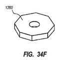
[000155]図34A乃至図34Gは、中を貫通する針のカニューレを受けるための孔を画定する磁気要素1360のさまざまな構成例を示している。磁気要素1360の示されているさまざまな形状構成として、正方形(図34A)、六角形(図34B)、三角形(図34C)、長方形(図34D)、卵形(図34E)、八角形(図34F)、および四角錐(図34G)が挙げられる。添付図に示されている磁気要素は、磁気要素を画定するために使用されうる多数のある幾何学的および他の形状の単なる例にすぎず、実際、本明細書に明示的に示されていない他の形状も企図される。
[000155] FIGS. 34A-34G illustrate various example configurations of a
[000156]本発明の実施形態は、本開示の精神から逸脱することなく他の特定の形式で実現することができる。説明されている実施形態は、すべての点で、説明のみを目的としており、制限することを目的としていないとみなされるべきである。したがって、これらの実施形態の範囲は、上記の説明ではなく、付属の請求項により指示される。請求項の同等性の意味および範囲内にある変更はすべて、本発明の範囲に含まれるものとする。
[形態1] 撮像技術に関連して患者の体内に医療用コンポーネントを挿入するための誘導システムにおいて、
プローブを備え、体内部分の標的の画像を生成する撮像デバイスと、
前記医療用コンポーネントに関係する検出可能な特性を検知する前記プローブに付属する少なくとも1つのセンサと、
少なくとも2つの空間次元における前記医療用コンポーネントの位置を判定するために前記少なくとも1つのセンサによって検知された前記検出可能な特性に関係するデータを使用するプロセッサと、
前記標的の前記画像とともに前記標的に関する前記医療用コンポーネントの前記位置を示すディスプレイとを備えた誘導システム。
[形態2] 形態1に記載の誘導システムにおいて、前記撮像デバイスは超音波撮像デバイスであり、前記プローブは超音波プローブを含み、前記少なくとも1つのセンサは前記超音波プローブに組み込まれた複数の磁気センサを含み、前記医療用コンポーネントは針を含み、前記検出可能な特性は前記針に関連する磁気要素の磁場であり、前記磁場は前記磁気センサによって検知されうる、誘導システム。
[形態3] 形態2に記載の誘導システムにおいて、前記磁気要素は、前記針のハブに永久的に、または取り外し可能に取り付けられた磁石を備えた、誘導システム。
[形態4] 形態2に記載の誘導システムにおいて、前記磁気センサのうちの1つまたは複数は、3つの空間次元内の前記針の前記磁気要素の位置ならびに前記磁気要素のピッチおよびヨー姿勢の判定を可能にするように直交検知
コンポーネントを備えた、誘導システム。
[形態5] 形態2に記載の誘導システムにおいて、前記誘導システムの使用中に前記針を保持するための手持ち式ニードルホルダをさらに備え、前記ニードルホルダは前記針を選択的に前進させるように構成され、前記磁気要素
は前記ニードルホルダに付属する、誘導システム。
[形態6] 形態1に記載の誘導システムにおいて、前記少なくとも1つのセンサは、前記プローブまたは前記撮像システムの他のコンポーネントに取り付け可能なセンサモジュール内に備えられた、誘導システム。
[形態7] 形態1に記載の誘導システムにおいて、前記医療用コンポーネントの前記検出可能な特性は、放射線信号、高周波信号、および光信号のうちの少なくとも1つに関係する、誘導システム。
[形態8] 形態2に記載の誘導システムにおいて、前記針の長さは、前記針の前記磁気要素の磁場強度の測定結果を利用して判定される、誘導システム。
[形態9] 撮像技術を利用して医療用コンポーネントを誘導して患者の体内に挿入するための方法において、
(a)前記体内の標的を撮像するステップと、
(b)前記医療用コンポーネントに関係する検出可能な特性を検知するステップと、
(c)前記検知された検出可能な特性に関係するデータによって少なくとも2つの空間
次元における前記医療用コンポーネントの位置を判定するステップと、
(d)前記標的の前記画像とともに前記標的に関する前記医療用コンポーネントの前記
位置を表示するステップと、を含む方法。
[形態10] 形態9に記載の誘導するための方法において、前記位置を表示するステップは、前記標的の前記画像とともに前記医療用コンポーネントの前記位置を表す画像を表示するステップをさらに含む、方法。
[形態11] 形態9に記載の誘導するための方法において、前記医療用コンポーネントの前記位置を判定するステップは、3つの空間次元における前記医療用コンポーネントの前記位置ならびにピッチおよびヨー配向のうちの少なくとも1つを判定するステップをさらに含む、方法。
[形態12] 形態9に記載の誘導するための方法において、前記医療用コンポーネントの前記検出可能な特性は、磁場であり、前記検出可能な特性を検知するステップは、少なくとも1つの磁気センサによって実行され、前記方法は前記検知可能な特性を検出する前に少なくとも1つの磁気センサのキャリブレーションを行って周囲磁場をなくすステップをさらに含む、方法。
[形態13] 形態9に記載の誘導するための方法において、前記標的に関する前記医療用コンポーネントの移動を追跡するために段階(b)、(c)、および(d)を反復的に繰り返すステップをさらに含む、方法。
[形態14] 形態9に記載の誘導するための方法において、前記標的を撮像するステップは、超音波撮像デバイスによって実行され、前記医療用コンポーネントの前記位置を判定するステップは、前記超音波撮像デバイスのプロセッサによって実行される、方法。
[形態15] 形態9に記載の誘導するための方法において、前記医療用コンポーネントは、針であり、前記方法は、前記針の長さを判定するステップをさらに含む、方法。
[形態16] 形態15に記載の誘導するための方法において、表示する前記標的で前記針を遮る確率の領域を計算するステップをさらに含む、方法。
[形態17] 形態9に記載の誘導するための方法において、前記位置を表示するステップは、前記標的の前記画像とともに前記医療用コンポーネントの前記位置を3次元で表示するステップをさらに含む、方法。
[形態18] 患者の体内への針の挿入を誘導するための誘導システムにおいて、
体内部分の標的を超音波で撮像するためのプローブを備えた超音波撮像デバイスと、
前記針に付属する磁気要素と、
それぞれが前記針の前記磁気要素の磁場を検知する前記プローブに付属する複数の磁気センサと、
3つの空間次元における前記針の位置を判定するために前記センサによって検知された磁場データを受信するプロセッサと、
前記標的の前記画像とともに前記針の前記判定された位置を表示するディスプレイとを備えた誘導システム。
[形態19] 形態18に記載の誘導システムにおいて、前記磁気要素は、前記針のハブ内に配置された永久磁石を備え、前記磁気要素と前記磁気センサとの間に物理的接続が存在しない、誘導システム。
[形態20] 形態18に記載の誘導システムにおいて、前記針は、前記誘導システムが前記針の長さを識別することを可能にするカラーコーディング、バーコード、およびRFIDチップのうちの1つをさらに備え、前記磁気センサは、前記プローブ内にアーチ形に分散される、誘導システム。
[形態21] 形態18に記載の誘導システムにおいて、前記磁気要素は、前記針のカニューレが受けられて通る孔を画定する永久磁石を備え、前記永久磁石の形状は、正方形、五角形、三角形、長方形、卵形、八角形、および角錐のうちの1つを画定する、誘導システム。
[形態22] 形態18に記載の誘導システムにおいて、前記磁気要素は、前記針のハブ内に備えられた複数の永久磁石を備えた、誘導システム。
[形態23] 形態18に記載の誘導システムにおいて、前記磁気要素は、前記針のカニューレの縦軸に直交する形で配置された少なくとも1つの棒磁石を備えた、誘導システム。
[形態24] 患者の体内への医療用コンポーネントの挿入を誘導するための誘導システムにおいて、
体内部分の標的を撮像するためのプローブを備えた撮像デバイスと、
前記プローブおよび前記医療用コンポーネントのうちの第1のものに付属する電磁信号放射源と、
前記プローブおよび前記医療用コンポーネントのうちの第2のものに付属する電磁信号センサと、
少なくとも2つの空間次元における前記医療用コンポーネントの位置を判定するために前記センサによって検出された前記電磁信号に関係するデータを受信するプロセッサと、
前記標的の前記画像とともに前記医療用コンポーネントの前記判定された位置を表示するディスプレイとを備えた誘導システム。
[形態25] 形態24に記載の誘導システムにおいて、前記医療用コンポーネントは、針を含み、前記源は、前記針内に取り外し可能に受けられるスタイレットに付属し、前記センサは、前記プローブ内に備えられた、誘導システム。
[形態26] 形態25に記載の誘導システムにおいて、前記スタイレットの前記源を前記プローブの前記センサと動作可能に接続するテザーをさらに備えた、誘導システム。
[形態27] 患者の体内への医療用コンポーネントの挿入を誘導するための誘導システムにおいて、
体内部分の標的を撮像するためのプローブを備えた撮像デバイスと、
前記プローブに付属する光源と、
前記医療用コンポーネントに付属する前記光源からの光を反射する反射面と、
前記反射面から反射された光を検出する前記プローブに付属する検出器と、
少なくとも2つの空間次元における前記医療用コンポーネントの位置を判定するために前記検出器によって検出された前記反射光に関係するデータを受信するプロセッサと、
前記標的の前記画像とともに前記医療用コンポーネントの前記判定された位置を表示するディスプレイとを備える誘導システム。
[形態28] 患者の体内への医療用コンポーネントの挿入を誘導するための誘導システムにおいて、
体内部分の標的を撮像するためのプローブを備えた撮像デバイスと、
前記医療用コンポーネントに付属する光源と、
前記医療用コンポーネントの前記光源が発した光を検出する前記プローブに付属する検出器と、
少なくとも2つの空間次元における前記医療用コンポーネントの位置を判定するために前記検出器によって検出された光に関係するデータを受信するプロセッサと、
前記標的の前記画像とともに前記医療用コンポーネントの前記判定された位置を表示するディスプレイとを備えた誘導システム。
[000156] Embodiments of the invention may be implemented in other specific forms without departing from the spirit of the disclosure. The described embodiments are to be considered in all respects only as illustrative and not restrictive. The scope of these embodiments is, therefore, indicated by the appended claims rather than by the foregoing description. All changes that come within the meaning and range of equivalency of the claims are to be embraced within their scope.
[Mode 1] In a guidance system for inserting medical components into a patient's body in relation to imaging technology,
An imaging device comprising a probe and generating an image of a target in the body part;
At least one sensor attached to the probe for sensing a detectable characteristic associated with the medical component;
A processor that uses data relating to the detectable property sensed by the at least one sensor to determine a position of the medical component in at least two spatial dimensions;
A guidance system comprising: a display showing the position of the medical component relative to the target along with the image of the target.
[Mode 2] In the guidance system according to mode 1, the imaging device is an ultrasound imaging device, the probe includes an ultrasound probe, and the at least one sensor is a plurality of magnets incorporated in the ultrasound probe. An induction system including a sensor, wherein the medical component includes a needle, the detectable property is a magnetic field of a magnetic element associated with the needle, and the magnetic field can be sensed by the magnetic sensor.
[Mode 3] The guidance system according to mode 2, wherein the magnetic element comprises a magnet that is permanently or removably attached to the hub of the needle.
[Mode 4] In the guidance system according to mode 2, one or more of the magnetic sensors may determine the position of the magnetic element of the needle and the pitch and yaw attitude of the magnetic element in three spatial dimensions. Guidance system with orthogonal sensing components to enable.
[Mode 5] The guidance system according to mode 2, further comprising a hand-held needle holder for holding the needle during use of the guidance system, wherein the needle holder is configured to selectively advance the needle. And the magnetic element is attached to the needle holder.
[Mode 6] The guidance system according to mode 1, wherein the at least one sensor is provided in a sensor module that can be attached to the probe or another component of the imaging system.
[Mode 7] The guidance system according to mode 1, wherein the detectable characteristic of the medical component is related to at least one of a radiation signal, a high-frequency signal, and an optical signal.
[Mode 8] The guidance system according to mode 2, wherein the length of the needle is determined using a measurement result of a magnetic field strength of the magnetic element of the needle.
[Mode 9] In a method for guiding and inserting a medical component into a patient's body using an imaging technique,
(A) imaging the target in the body;
(B) sensing a detectable characteristic associated with the medical component;
(C) determining a position of the medical component in at least two spatial dimensions according to data related to the sensed detectable property;
(D) displaying the position of the medical component with respect to the target along with the image of the target.
[Mode 10] The method for guiding according to mode 9, wherein displaying the position further includes displaying an image representing the position of the medical component together with the image of the target.
[Form 11] In the method for guiding according to aspect 9, the step of determining the position of the medical component includes at least one of the position and pitch and yaw orientation of the medical component in three spatial dimensions. The method further comprising the step of determining one.
[Mode 12] The method for guiding according to mode 9, wherein the detectable characteristic of the medical component is a magnetic field, and the step of sensing the detectable characteristic is performed by at least one magnetic sensor. And the method further comprises calibrating at least one magnetic sensor to eliminate ambient magnetic fields prior to detecting the detectable characteristic.
[Form 13] The method for guiding according to aspect 9, wherein the steps (b), (c), and (d) are iteratively repeated to track movement of the medical component relative to the target. Further comprising a method.
[Form 14] In the method for guiding according to aspect 9, the step of imaging the target is performed by an ultrasound imaging device, and the step of determining the position of the medical component is the ultrasound imaging device. The method performed by the processor of the.
[Form 15] The method for guiding according to aspect 9, wherein the medical component is a needle, and the method further includes determining a length of the needle.
[Mode 16] The method for guidance according to mode 15, further comprising calculating a region of probability of blocking the needle with the target to be displayed.
[Form 17] The method for guiding according to aspect 9, wherein displaying the position further includes displaying the position of the medical component together with the image of the target in three dimensions.
[Form 18] In a guidance system for guiding the insertion of a needle into a patient's body,
An ultrasonic imaging device including a probe for imaging a target of a body part with ultrasound;
A magnetic element attached to the needle;
A plurality of magnetic sensors each attached to the probe for detecting a magnetic field of the magnetic element of the needle;
A processor for receiving magnetic field data sensed by the sensor to determine the position of the needle in three spatial dimensions;
A guidance system comprising: a display that displays the determined position of the needle along with the image of the target.
[Form 19] The guidance system according to Form 18, wherein the magnetic element comprises a permanent magnet disposed in the hub of the needle, and there is no physical connection between the magnetic element and the magnetic sensor, Guidance system.
[Mode 20] The guidance system according to mode 18, wherein the needle further includes one of a color coding, a barcode, and an RFID chip that allows the guidance system to identify the length of the needle. A guidance system, wherein the magnetic sensors are distributed in an arch form in the probe.
[Mode 21] In the guidance system according to mode 18, the magnetic element includes a permanent magnet defining a hole through which the needle cannula is received, and the shape of the permanent magnet is square, pentagon, triangle, rectangular A guiding system defining one of: oval, octagon, and pyramid.
[Mode 22] The guidance system according to mode 18, wherein the magnetic element includes a plurality of permanent magnets provided in a hub of the needle.
[Form 23] The guidance system according to form 18, wherein the magnetic element comprises at least one bar magnet disposed perpendicular to the longitudinal axis of the cannula of the needle.
[Form 24] In a guidance system for guiding insertion of a medical component into a patient's body,
An imaging device comprising a probe for imaging a target of a body part;
An electromagnetic signal radiation source attached to the probe and a first one of the medical components;
An electromagnetic signal sensor attached to the probe and a second one of the medical components;
A processor for receiving data related to the electromagnetic signal detected by the sensor to determine a position of the medical component in at least two spatial dimensions;
A guidance system comprising: a display for displaying the determined position of the medical component along with the image of the target.
[Form 25] The guidance system according to
[Mode 26] The guidance system according to mode 25, further comprising a tether operably connecting the source of the stylet with the sensor of the probe.
[Form 27] In a guidance system for guiding the insertion of a medical component into a patient's body,
An imaging device comprising a probe for imaging a target of a body part;
A light source attached to the probe;
A reflective surface for reflecting light from the light source attached to the medical component;
A detector attached to the probe for detecting light reflected from the reflecting surface;
A processor for receiving data related to the reflected light detected by the detector to determine the position of the medical component in at least two spatial dimensions;
A guidance system comprising: a display that displays the determined position of the medical component along with the image of the target.
[Form 28] In a guidance system for guiding insertion of a medical component into a patient's body,
An imaging device comprising a probe for imaging a target of a body part;
A light source attached to the medical component;
A detector attached to the probe for detecting light emitted by the light source of the medical component;
A processor for receiving data related to light detected by the detector to determine a position of the medical component in at least two spatial dimensions;
A guidance system comprising: a display for displaying the determined position of the medical component along with the image of the target.
Claims (19)
プローブを備え、体内部分の標的の画像を生成する撮像デバイスと、
前記プローブとは独立に移動可能な前記医療用コンポーネントに関係する検出可能な特性を検知する前記プローブに付属する少なくとも1つのセンサと、
少なくとも2つの空間次元における前記医療用コンポーネントの位置を判定するために前記少なくとも1つのセンサによって検知された前記検出可能な特性に関係するデータを使用するプロセッサと、
前記標的の前記画像とともに前記標的に関する前記医療用コンポーネントの前記位置を示すディスプレイとを備え、
前記撮像デバイスは超音波撮像デバイスであり、前記プローブは超音波プローブを含み、前記少なくとも1つのセンサは前記超音波プローブに組み込まれた複数の磁気センサを含み、前記医療用コンポーネントは針を含み、前記検出可能な特性は前記針に関連する磁気要素の磁場であり、前記磁場は前記磁気センサによって検知されることが可能であり、
前記針の長さは、前記針の前記磁気要素の磁場強度の測定結果を利用して判定される、
誘導システム。 In a guidance system for inserting medical components into a patient's body in connection with imaging technology,
An imaging device comprising a probe and generating an image of a target in the body part;
At least one sensor associated with the probe that senses a detectable characteristic associated with the medical component that is movable independently of the probe;
A processor that uses data relating to the detectable property sensed by the at least one sensor to determine a position of the medical component in at least two spatial dimensions;
A display showing the position of the medical component with respect to the target along with the image of the target;
The imaging device is an ultrasound imaging device, the probe comprises an ultrasound probe, the at least one sensor comprises a plurality of magnetic sensors incorporated in the ultrasound probe, and the medical component comprises a needle; The detectable property is a magnetic field of a magnetic element associated with the needle, the magnetic field being detectable by the magnetic sensor;
The length of the needle is determined using a measurement result of the magnetic field strength of the magnetic element of the needle,
Guidance system.
(a)前記プローブに設けられた撮像手段が、前記体内の標的を撮像するステップと、
(b)前記プローブに設けられた検知手段が、前記医療用コンポーネントに関係する検出可能な特性を検知するステップと、
(c)第1の判定手段が、前記検知された検出可能な特性に関係するデータによって少なくとも2つの空間次元における前記医療用コンポーネントの位置を判定するステップと、
(d)表示手段が、前記標的の前記画像とともに前記標的に関する前記医療用コンポーネントの前記位置を表示するステップとを含み、
前記撮像手段は超音波撮像デバイスであり、前記プローブは超音波プローブを含み、前記検知手段は、前記超音波プローブに組み込まれた複数の磁気センサを含み、前記医療用コンポーネントは針を含み、
前記ステップ(b)において、前記検出可能な特性は前記針に関連する磁気要素の磁場であり、前記磁場が前記磁気センサによって検知され、前記ステップ(c)は、第2の判定手段が前記針の前記磁気要素の磁場強度の測定結果を利用して前記針の長さを判定することを含む、
方法。 In a method of using imaging technology to control a system for guiding and inserting a medical component movable independently of a probe into a patient's body,
(A) an imaging unit provided in the probe images the target in the body;
(B) detecting means provided on the probe detecting a detectable characteristic related to the medical component;
(C) first determining means determining a position of the medical component in at least two spatial dimensions according to data relating to the detected detectable property;
(D) displaying means displaying the position of the medical component relative to the target together with the image of the target;
The imaging means is an ultrasound imaging device, the probe comprises an ultrasound probe, the sensing means comprises a plurality of magnetic sensors incorporated in the ultrasound probe, and the medical component comprises a needle;
In the step (b), the detectable characteristic is a magnetic field of a magnetic element associated with the needle, the magnetic field is detected by the magnetic sensor, and in the step (c), a second determination means is configured by the needle. Determining the length of the needle using the measurement result of the magnetic field strength of the magnetic element of
Method.
体内部分の標的を超音波で撮像するための超音波プローブを備えた超音波撮像デバイスと、
前記プローブと独立に移動可能な前記針に付属する磁気要素と、
それぞれが前記針の前記磁気要素の磁場を検知する前記プローブに付属する複数の磁気センサと、
3つの空間次元における前記針の位置を判定するために前記センサによって検知された磁場データを受信するプロセッサと、
前記標的の前記画像とともに前記針の前記判定された位置を表示するディスプレイとを備え、
前記複数の磁気センサは、前記プローブに組み込まれており、前記針の長さが、前記針の前記磁気要素の磁場強度の測定結果を利用して判定される、
誘導システム。 In a guidance system for guiding the insertion of a needle into a patient's body,
An ultrasound imaging device including an ultrasound probe for imaging a target in the body part with ultrasound;
A magnetic element attached to the needle movable independently of the probe;
A plurality of magnetic sensors each attached to the probe for detecting a magnetic field of the magnetic element of the needle;
A processor for receiving magnetic field data sensed by the sensor to determine the position of the needle in three spatial dimensions;
A display for displaying the determined position of the needle together with the image of the target;
The plurality of magnetic sensors are incorporated in the probe, and the length of the needle is determined using a measurement result of the magnetic field strength of the magnetic element of the needle.
Guidance system.
前記永久磁石の形状は、正方形、五角形、三角形、長方形、卵形、八角形、および角錐のうちの1つを画定する請求項14に記載の誘導システム。 The magnetic element comprises a permanent magnet defining a hole through which the needle cannula is received;
15. The guidance system of claim 14 , wherein the shape of the permanent magnet defines one of a square, pentagon, triangle, rectangle, oval, octagon, and pyramid.
Applications Claiming Priority (3)
| Application Number | Priority Date | Filing Date | Title |
|---|---|---|---|
| US34977110P | 2010-05-28 | 2010-05-28 | |
| US61/349,771 | 2010-05-28 | ||
| PCT/US2011/038391 WO2011150358A1 (en) | 2010-05-28 | 2011-05-27 | Insertion guidance system for needles and medical components |
Publications (2)
| Publication Number | Publication Date |
|---|---|
| JP2013526959A JP2013526959A (en) | 2013-06-27 |
| JP5980201B2 true JP5980201B2 (en) | 2016-08-31 |
Family
ID=45004427
Family Applications (3)
| Application Number | Title | Priority Date | Filing Date |
|---|---|---|---|
| JP2013512046A Active JP5980201B2 (en) | 2010-05-28 | 2011-05-27 | Insertion guidance system for needles and medical components |
| JP2013512051A Active JP5868961B2 (en) | 2010-05-28 | 2011-05-27 | Device for use with a needle insertion guidance system |
| JP2016000437A Ceased JP2016104192A (en) | 2010-05-28 | 2016-01-05 | Apparatus for use with needle insertion guidance system |
Family Applications After (2)
| Application Number | Title | Priority Date | Filing Date |
|---|---|---|---|
| JP2013512051A Active JP5868961B2 (en) | 2010-05-28 | 2011-05-27 | Device for use with a needle insertion guidance system |
| JP2016000437A Ceased JP2016104192A (en) | 2010-05-28 | 2016-01-05 | Apparatus for use with needle insertion guidance system |
Country Status (8)
| Country | Link |
|---|---|
| US (2) | US9554716B2 (en) |
| EP (4) | EP3662827B1 (en) |
| JP (3) | JP5980201B2 (en) |
| CN (2) | CN103037761B (en) |
| CA (3) | CA2800813C (en) |
| ES (5) | ES2863568T3 (en) |
| MX (2) | MX2012013858A (en) |
| WO (1) | WO2011150358A1 (en) |
Families Citing this family (168)
| Publication number | Priority date | Publication date | Assignee | Title |
|---|---|---|---|---|
| US8784336B2 (en) | 2005-08-24 | 2014-07-22 | C. R. Bard, Inc. | Stylet apparatuses and methods of manufacture |
| US7728868B2 (en) | 2006-08-02 | 2010-06-01 | Inneroptic Technology, Inc. | System and method of providing real-time dynamic imagery of a medical procedure site using multiple modalities |
| US7794407B2 (en) | 2006-10-23 | 2010-09-14 | Bard Access Systems, Inc. | Method of locating the tip of a central venous catheter |
| US8388546B2 (en) | 2006-10-23 | 2013-03-05 | Bard Access Systems, Inc. | Method of locating the tip of a central venous catheter |
| US8849382B2 (en) | 2007-11-26 | 2014-09-30 | C. R. Bard, Inc. | Apparatus and display methods relating to intravascular placement of a catheter |
| ES2465915T3 (en) | 2007-11-26 | 2014-06-09 | C.R. Bard, Inc. | Integrated system for intravascular catheter placement |
| US9649048B2 (en) | 2007-11-26 | 2017-05-16 | C. R. Bard, Inc. | Systems and methods for breaching a sterile field for intravascular placement of a catheter |
| US10449330B2 (en) * | 2007-11-26 | 2019-10-22 | C. R. Bard, Inc. | Magnetic element-equipped needle assemblies |
| US8781555B2 (en) | 2007-11-26 | 2014-07-15 | C. R. Bard, Inc. | System for placement of a catheter including a signal-generating stylet |
| US10751509B2 (en) | 2007-11-26 | 2020-08-25 | C. R. Bard, Inc. | Iconic representations for guidance of an indwelling medical device |
| US9521961B2 (en) | 2007-11-26 | 2016-12-20 | C. R. Bard, Inc. | Systems and methods for guiding a medical instrument |
| US10524691B2 (en) | 2007-11-26 | 2020-01-07 | C. R. Bard, Inc. | Needle assembly including an aligned magnetic element |
| WO2009094646A2 (en) | 2008-01-24 | 2009-07-30 | The University Of North Carolina At Chapel Hill | Methods, systems, and computer readable media for image guided ablation |
| US8478382B2 (en) | 2008-02-11 | 2013-07-02 | C. R. Bard, Inc. | Systems and methods for positioning a catheter |
| US8340379B2 (en) | 2008-03-07 | 2012-12-25 | Inneroptic Technology, Inc. | Systems and methods for displaying guidance data based on updated deformable imaging data |
| EP2108328B2 (en) * | 2008-04-09 | 2020-08-26 | Brainlab AG | Image-based control method for medicinal devices |
| EP2313143B1 (en) | 2008-08-22 | 2014-09-24 | C.R. Bard, Inc. | Catheter assembly including ecg sensor and magnetic assemblies |
| US8437833B2 (en) | 2008-10-07 | 2013-05-07 | Bard Access Systems, Inc. | Percutaneous magnetic gastrostomy |
| JP5789195B2 (en) | 2008-12-08 | 2015-10-07 | シリコンバレー メディカル インスツルメンツ インコーポレイテッド | Catheter system for image guidance |
| WO2010080637A1 (en) * | 2008-12-18 | 2010-07-15 | C. R. Bard, Inc. | Needle guides for a sonographic imaging device |
| US11464578B2 (en) | 2009-02-17 | 2022-10-11 | Inneroptic Technology, Inc. | Systems, methods, apparatuses, and computer-readable media for image management in image-guided medical procedures |
| US8641621B2 (en) | 2009-02-17 | 2014-02-04 | Inneroptic Technology, Inc. | Systems, methods, apparatuses, and computer-readable media for image management in image-guided medical procedures |
| US8554307B2 (en) | 2010-04-12 | 2013-10-08 | Inneroptic Technology, Inc. | Image annotation in image-guided medical procedures |
| US8690776B2 (en) | 2009-02-17 | 2014-04-08 | Inneroptic Technology, Inc. | Systems, methods, apparatuses, and computer-readable media for image guided surgery |
| RU2691318C2 (en) | 2009-06-12 | 2019-06-11 | Бард Аксесс Системс, Инк. | Method for positioning catheter end |
| US9532724B2 (en) | 2009-06-12 | 2017-01-03 | Bard Access Systems, Inc. | Apparatus and method for catheter navigation using endovascular energy mapping |
| WO2011019760A2 (en) | 2009-08-10 | 2011-02-17 | Romedex International Srl | Devices and methods for endovascular electrography |
| EP2482719A4 (en) | 2009-09-29 | 2016-03-09 | Bard Inc C R | Stylets for use with apparatus for intravascular placement of a catheter |
| US11103213B2 (en) | 2009-10-08 | 2021-08-31 | C. R. Bard, Inc. | Spacers for use with an ultrasound probe |
| US8761862B2 (en) * | 2009-10-09 | 2014-06-24 | Stephen F. Ridley | Ultrasound guided probe device and sterilizable shield for same |
| CN102821679B (en) | 2010-02-02 | 2016-04-27 | C·R·巴德股份有限公司 | For the apparatus and method that catheter navigation and end are located |
| US9733235B2 (en) | 2010-05-28 | 2017-08-15 | California Instute Of Technology | Methods and design of membrane filters |
| EP2912999B1 (en) | 2010-05-28 | 2022-06-29 | C. R. Bard, Inc. | Apparatus for use with needle insertion guidance system |
| CN103037761B (en) | 2010-05-28 | 2016-11-02 | C·R·巴德股份有限公司 | Insertion for pin and medical components guides system |
| WO2012021542A2 (en) | 2010-08-09 | 2012-02-16 | C.R. Bard, Inc. | Support and cover structures for an ultrasound probe head |
| BR112013002431B1 (en) | 2010-08-20 | 2021-06-29 | C.R. Bard, Inc | SYSTEM FOR RECONFIRMING THE POSITION OF A CATHETER INSIDE A PATIENT |
| US8425425B2 (en) | 2010-09-20 | 2013-04-23 | M. Dexter Hagy | Virtual image formation method for an ultrasound device |
| WO2012058461A1 (en) | 2010-10-29 | 2012-05-03 | C.R.Bard, Inc. | Bioimpedance-assisted placement of a medical device |
| BR112013030348A2 (en) | 2011-07-06 | 2017-08-01 | Bard Inc C R | method for determining a length of a medical component for use with an ultrasound imaging system including a probe; method for determining a needle length by a needle guidance system; and needle length determination system for an ultrasound imaging device including an ultrasound probe |
| USD699359S1 (en) | 2011-08-09 | 2014-02-11 | C. R. Bard, Inc. | Ultrasound probe head |
| USD724745S1 (en) | 2011-08-09 | 2015-03-17 | C. R. Bard, Inc. | Cap for an ultrasound probe |
| PL2939601T3 (en) | 2011-09-06 | 2019-04-30 | Ezono Ag | Magnetic medical device |
| WO2013070775A1 (en) | 2011-11-07 | 2013-05-16 | C.R. Bard, Inc | Ruggedized ultrasound hydrogel insert |
| JP2013123459A (en) | 2011-12-13 | 2013-06-24 | Seiko Epson Corp | Living body inspecting probe |
| WO2013116240A1 (en) | 2012-01-30 | 2013-08-08 | Inneroptic Technology, Inc. | Multiple medical device guidance |
| DE102012002412A1 (en) * | 2012-02-09 | 2013-08-14 | Bernd Meier | Device for determination of position of puncture needle in workspace of ultrasound probe for human body, has processor unit introducing stitch projection and penetration depth of needle together with image for representation of projection |
| US10852093B2 (en) | 2012-05-22 | 2020-12-01 | Haptech, Inc. | Methods and apparatuses for haptic systems |
| US9146069B2 (en) * | 2012-05-22 | 2015-09-29 | Haptech, Inc. | Method and apparatus for firearm recoil simulation |
| EP2861153A4 (en) | 2012-06-15 | 2016-10-19 | Bard Inc C R | Apparatus and methods for detection of a removable cap on an ultrasound probe |
| GB2503668B (en) * | 2012-07-03 | 2018-02-07 | Univ Hospitals Of Leicester Nhs Trust | Delivery apparatus |
| RU2669621C2 (en) * | 2012-09-28 | 2018-10-12 | Си. Ар. БАРД, ИНК. | Needle assembly including an aligned magnetic element |
| CA2928460C (en) | 2012-10-30 | 2021-10-19 | Truinject Medical Corp. | System for injection training |
| KR101478623B1 (en) * | 2012-11-07 | 2015-01-02 | 삼성메디슨 주식회사 | Ultrasound system and method for providing guide line of needle |
| US20140257080A1 (en) * | 2013-03-05 | 2014-09-11 | Ezono Ag | System for ultrasound image guided procedure |
| US9257220B2 (en) | 2013-03-05 | 2016-02-09 | Ezono Ag | Magnetization device and method |
| US9459087B2 (en) | 2013-03-05 | 2016-10-04 | Ezono Ag | Magnetic position detection system |
| GB201303917D0 (en) | 2013-03-05 | 2013-04-17 | Ezono Ag | System for image guided procedure |
| US10314559B2 (en) | 2013-03-14 | 2019-06-11 | Inneroptic Technology, Inc. | Medical device guidance |
| US10188831B2 (en) | 2013-03-14 | 2019-01-29 | Angiodynamics, Inc. | Systems and methods for catheter tip placement using ECG |
| US20140275990A1 (en) * | 2013-03-15 | 2014-09-18 | Soma Access Systems, Llc | Ultrasound Guidance System Including Tagged Probe Assembly |
| JP6453344B2 (en) * | 2014-01-10 | 2019-01-16 | ソマ・リサーチ・エルエルシー | Needle guidance system for use with an ultrasonic device |
| WO2015109251A1 (en) | 2014-01-17 | 2015-07-23 | Truinject Medical Corp. | Injection site training system |
| US10492767B2 (en) | 2014-01-20 | 2019-12-03 | General Electric Company | Method and system for sequential needle recalibration |
| EP3205270B1 (en) * | 2014-01-29 | 2018-12-19 | Becton, Dickinson and Company | Wearable electronic device for enhancing visualization during insertion of an invasive device |
| US9839372B2 (en) | 2014-02-06 | 2017-12-12 | C. R. Bard, Inc. | Systems and methods for guidance and placement of an intravascular device |
| WO2015138883A1 (en) | 2014-03-13 | 2015-09-17 | New York University | Position guidance device with bubble level |
| WO2015141881A1 (en) * | 2014-03-21 | 2015-09-24 | 알피니언메디칼시스템 주식회사 | Optical scanning device and ultrasonic probe comprising same |
| US20150282734A1 (en) | 2014-04-08 | 2015-10-08 | Timothy Schweikert | Medical device placement system and a method for its use |
| US11197721B2 (en) | 2014-07-16 | 2021-12-14 | Koninklike Philips N.V. | Ultrasound tracking apparatus for disposable biopsy needles |
| US10238363B2 (en) | 2014-08-21 | 2019-03-26 | Richard D. Striano | Needle guide for ultrasound transducer |
| US9901406B2 (en) | 2014-10-02 | 2018-02-27 | Inneroptic Technology, Inc. | Affected region display associated with a medical device |
| WO2016081023A1 (en) | 2014-11-18 | 2016-05-26 | C.R. Bard, Inc. | Ultrasound imaging system having automatic image presentation |
| US10646201B2 (en) | 2014-11-18 | 2020-05-12 | C. R. Bard, Inc. | Ultrasound imaging system having automatic image presentation |
| US10188467B2 (en) | 2014-12-12 | 2019-01-29 | Inneroptic Technology, Inc. | Surgical guidance intersection display |
| US10973584B2 (en) | 2015-01-19 | 2021-04-13 | Bard Access Systems, Inc. | Device and method for vascular access |
| US10349890B2 (en) | 2015-06-26 | 2019-07-16 | C. R. Bard, Inc. | Connector interface for ECG-based catheter positioning system |
| US9949700B2 (en) | 2015-07-22 | 2018-04-24 | Inneroptic Technology, Inc. | Medical device approaches |
| US20180303559A1 (en) * | 2015-10-19 | 2018-10-25 | New York University | Electronic position guidance device with real-time auditory and visual feedback |
| EP3391083B1 (en) * | 2015-12-16 | 2021-08-11 | Koninklijke Philips N.V. | Interventional device recognition |
| CN108463179B (en) * | 2016-01-08 | 2021-04-27 | 波士顿科学医学有限公司 | Surgical guiding apparatus, system and method |
| US11000207B2 (en) | 2016-01-29 | 2021-05-11 | C. R. Bard, Inc. | Multiple coil system for tracking a medical device |
| US9675319B1 (en) | 2016-02-17 | 2017-06-13 | Inneroptic Technology, Inc. | Loupe display |
| WO2017151441A2 (en) | 2016-02-29 | 2017-09-08 | Truinject Medical Corp. | Cosmetic and therapeutic injection safety systems, methods, and devices |
| EP3423972A1 (en) | 2016-03-02 | 2019-01-09 | Truinject Corp. | Sensory enhanced environments for injection aid and social training |
| WO2017151716A1 (en) | 2016-03-02 | 2017-09-08 | Truinject Medical Corp. | System for determining a three-dimensional position of a testing tool |
| WO2017197247A2 (en) | 2016-05-12 | 2017-11-16 | Affera, Inc. | Anatomical model controlling |
| JP6963567B2 (en) | 2016-05-19 | 2021-11-10 | アシスト・メディカル・システムズ,インコーポレイテッド | Position detection in intravascular processes |
| CN109561879B (en) * | 2016-05-19 | 2022-03-29 | 阿西斯特医疗系统有限公司 | Position sensing in intravascular procedures |
| US11826522B2 (en) | 2016-06-01 | 2023-11-28 | Becton, Dickinson And Company | Medical devices, systems and methods utilizing permanent magnet and magnetizable feature |
| US11413429B2 (en) * | 2016-06-01 | 2022-08-16 | Becton, Dickinson And Company | Medical devices, systems and methods utilizing permanent magnet and magnetizable feature |
| US20170347914A1 (en) | 2016-06-01 | 2017-12-07 | Becton, Dickinson And Company | Invasive Medical Devices Including Magnetic Region And Systems And Methods |
| US10278778B2 (en) | 2016-10-27 | 2019-05-07 | Inneroptic Technology, Inc. | Medical device navigation using a virtual 3D space |
| WO2018098196A1 (en) * | 2016-11-23 | 2018-05-31 | Clear Guide Medical, Inc. | System and methods for navigating interventional instrumentation |
| EP3544518A1 (en) | 2016-11-23 | 2019-10-02 | C.R. Bard, Inc. | Single insertion multiple sample biopsy apparatus |
| EP3551274B1 (en) * | 2016-12-14 | 2020-07-08 | C.R. Bard, Inc. | Needles for use with system for guiding a medical instrument |
| KR102015520B1 (en) | 2017-01-13 | 2019-08-28 | 주식회사 루트로닉 | An treatment apparatus and a method for controlling that |
| EP3596721B1 (en) | 2017-01-23 | 2023-09-06 | Truinject Corp. | Syringe dose and position measuring apparatus |
| ES2848830T3 (en) | 2017-04-27 | 2021-08-12 | Bard Access Systems Inc | Guiding system to guide the insertion of a needle into the body of a patient comprising a magnetization system for needle assemblies |
| CN110621215A (en) * | 2017-04-28 | 2019-12-27 | 巴德血管外围设备公司 | Implantable unique device identification and detection system |
| WO2018208823A1 (en) * | 2017-05-09 | 2018-11-15 | Boston Scientific Scimed, Inc. | Operating room devices, methods, and systems |
| US10667869B2 (en) * | 2017-05-17 | 2020-06-02 | General Electric Company | Guidance system for needle procedures |
| US11096758B2 (en) | 2017-05-23 | 2021-08-24 | Boston Scientific Limited | Surgical guidance systems, devices, and methods |
| CN107049594B (en) | 2017-06-14 | 2020-04-07 | 京东方科技集团股份有限公司 | Recovery device and magnetic particle recovery method |
| EP3417790A1 (en) | 2017-06-20 | 2018-12-26 | eZono AG | System and method for image-guided procedure analysis |
| US11259879B2 (en) | 2017-08-01 | 2022-03-01 | Inneroptic Technology, Inc. | Selective transparency to assist medical device navigation |
| DE102017008148A1 (en) * | 2017-08-29 | 2019-02-28 | Joimax Gmbh | Sensor unit, intraoperative navigation system and method for detecting a surgical instrument |
| US11583249B2 (en) * | 2017-09-08 | 2023-02-21 | Biosense Webster (Israel) Ltd. | Method and apparatus for performing non-fluoroscopic transseptal procedure |
| JP7291697B2 (en) * | 2017-11-09 | 2023-06-15 | アセッサー・ヘルス・インコーポレーテッド | A system for controlling ablation therapy and visualization |
| US11484365B2 (en) | 2018-01-23 | 2022-11-01 | Inneroptic Technology, Inc. | Medical image guidance |
| US10992078B2 (en) | 2018-01-29 | 2021-04-27 | Bard Access Systems, Inc. | Connection system for establishing an electrical connection through a drape and methods thereof |
| CN111989061A (en) | 2018-04-13 | 2020-11-24 | 卡尔史托斯两合公司 | Guidance system, method and device thereof |
| US20210244434A1 (en) * | 2018-04-20 | 2021-08-12 | Stent Tek Limited | Apparatus for orientation display and alignment in percutaneous devices |
| US10772696B2 (en) | 2018-05-18 | 2020-09-15 | Bard Access Systems, Inc. | Connection systems and methods thereof for establishing an electrical connection through a drape |
| CN112584756A (en) * | 2018-08-22 | 2021-03-30 | 巴德阿克塞斯系统股份有限公司 | System and method for infrared enhanced ultrasound visualization |
| EP3852622A1 (en) | 2018-10-16 | 2021-07-28 | Bard Access Systems, Inc. | Safety-equipped connection systems and methods thereof for establishing electrical connections |
| SE544094C2 (en) * | 2018-11-05 | 2021-12-21 | Scibase Ab | Medical device for analyzing epithelial barrier function using electrical impedance spectroscopy |
| WO2020118190A1 (en) * | 2018-12-07 | 2020-06-11 | Veran Medical Technologies, Inc. | Endobronchial catheter system and method for rapid diagnosis of lung disease |
| KR102238250B1 (en) * | 2018-12-07 | 2021-04-09 | 인제대학교 산학협력단 | Laser guide arm for ultra sound guided nerve block and vessel access |
| US11801113B2 (en) * | 2018-12-13 | 2023-10-31 | Covidien Lp | Thoracic imaging, distance measuring, and notification system and method |
| WO2020154543A1 (en) * | 2019-01-23 | 2020-07-30 | Affera, Inc. | Systems and methods for therapy annotation |
| EP3917406A4 (en) | 2019-01-30 | 2023-01-18 | Bard Access Systems, Inc. | Systems and methods for tracking medical devices |
| US20200281561A1 (en) * | 2019-03-05 | 2020-09-10 | Ethos Medical, Inc. | Systems, Methods, and Devices for Instrument Guidance |
| KR20200120062A (en) * | 2019-04-11 | 2020-10-21 | 삼성메디슨 주식회사 | Ultrasonic probe and ultrasonic imaging apparatus having the same |
| US20220241045A1 (en) * | 2019-05-15 | 2022-08-04 | Stryker Corporation | Powered Surgical Drill Having Rotating Field Bit Identification |
| WO2020243015A1 (en) * | 2019-05-24 | 2020-12-03 | Berkeley Lights, Inc. | Systems and methods for optimizing an instrument system workflow |
| US11730443B2 (en) | 2019-06-13 | 2023-08-22 | Fujifilm Sonosite, Inc. | On-screen markers for out-of-plane needle guidance |
| EP3997497A4 (en) | 2019-07-29 | 2023-07-05 | Bard Access Systems, Inc. | Connection systems and methods for establishing optical and electrical connections through a drape |
| US11931112B2 (en) | 2019-08-12 | 2024-03-19 | Bard Access Systems, Inc. | Shape-sensing system and methods for medical devices |
| CN114222532A (en) * | 2019-08-16 | 2022-03-22 | 富士胶片株式会社 | Ultrasonic diagnostic apparatus and method for controlling ultrasonic diagnostic apparatus |
| CN112438801A (en) | 2019-09-04 | 2021-03-05 | 巴德阿克塞斯系统股份有限公司 | System and method for ultrasound probe tracking status indicator |
| EP4025151A4 (en) * | 2019-09-04 | 2023-09-06 | Bard Access Systems, Inc. | Needle-guidance systems, devices, and method thereof including rfid technology |
| CN112535499A (en) | 2019-09-20 | 2021-03-23 | 巴德阿克塞斯系统股份有限公司 | Automated vessel detection tool and method |
| CN112568975A (en) | 2019-09-27 | 2021-03-30 | 巴德阿克塞斯系统股份有限公司 | Constant torque intraosseous access device and method |
| EP4031027A4 (en) | 2019-09-27 | 2023-09-13 | Bard Access Systems, Inc. | Various operating mechanisms for intraosseous access medical devices and methods thereof |
| US11517349B2 (en) | 2019-09-27 | 2022-12-06 | Bard Access Systems, Inc. | Autovance feature of an intraosseous device |
| EP4061272A4 (en) * | 2019-11-25 | 2023-11-22 | Bard Access Systems, Inc. | Shape-sensing systems with filters and methods thereof |
| EP4061466A4 (en) | 2019-11-25 | 2023-11-22 | Bard Access Systems, Inc. | Optical tip-tracking systems and methods thereof |
| WO2021113371A1 (en) * | 2019-12-03 | 2021-06-10 | Gyrus Acmi, Inc. D/B/A Olympus Surgical Technologies America | Medical instrument guidance systems and methods |
| US20210186456A1 (en) * | 2019-12-19 | 2021-06-24 | Bard Access Systems, Inc. | Needle Sterility Breach Warning Using Magnetic Needle Tracking |
| WO2021137109A1 (en) * | 2019-12-31 | 2021-07-08 | Auris Health, Inc. | Alignment techniques for percutaneous access |
| WO2021137108A1 (en) * | 2019-12-31 | 2021-07-08 | Auris Health, Inc. | Alignment interfaces for percutaneous access |
| KR102372064B1 (en) * | 2020-02-04 | 2022-03-08 | 인제대학교 산학협력단 | Ultrasound Imaging System and Needle Insertion Guide Method Using thereof |
| WO2021173861A1 (en) | 2020-02-28 | 2021-09-02 | Bard Access Systems, Inc. | Optical connection systems and methods thereof |
| EP4127798A1 (en) | 2020-03-30 | 2023-02-08 | Bard Access Systems, Inc. | Optical and electrical diagnostic systems and methods thereof |
| US11896264B2 (en) | 2020-04-21 | 2024-02-13 | Bard Access Systems, Inc. | Reusable push-activated intraosseous access device |
| CN111552415B (en) * | 2020-04-30 | 2023-03-31 | 中国航空无线电电子研究所 | High-safety-level touch device and method for airplane |
| WO2021247723A2 (en) | 2020-06-03 | 2021-12-09 | Bard Access Systems, Inc. | Intraosseous device including a sensing obturator |
| WO2021263023A1 (en) | 2020-06-26 | 2021-12-30 | Bard Access Systems, Inc. | Malposition detection system |
| US11883609B2 (en) | 2020-06-29 | 2024-01-30 | Bard Access Systems, Inc. | Automatic dimensional frame reference for fiber optic |
| CN113907705A (en) | 2020-07-10 | 2022-01-11 | 巴德阿克塞斯系统股份有限公司 | Continuous optical fiber function monitoring and self-diagnosis reporting system |
| EP4181791A1 (en) | 2020-07-21 | 2023-05-24 | Bard Access Systems, Inc. | System, method and apparatus for magnetic tracking of ultrasound probe and generation of 3d visualization thereof |
| EP4188212A1 (en) | 2020-08-03 | 2023-06-07 | Bard Access Systems, Inc. | Bragg grated fiber optic fluctuation sensing and monitoring system |
| CN215839160U (en) | 2020-09-03 | 2022-02-18 | 巴德阿克塞斯系统股份有限公司 | Portable ultrasound probe and system |
| EP4203800A1 (en) | 2020-09-08 | 2023-07-05 | Bard Access Systems, Inc. | Dynamically adjusting ultrasound-imaging systems and methods thereof |
| CN114246614A (en) | 2020-09-25 | 2022-03-29 | 巴德阿克塞斯系统股份有限公司 | Ultrasound imaging system and minimum catheter length tool |
| CN216167527U (en) | 2020-09-29 | 2022-04-05 | 巴德阿克塞斯系统股份有限公司 | Hands-free ultrasound probe, assembly and system |
| CN216435468U (en) | 2020-09-30 | 2022-05-03 | 巴德阿克塞斯系统股份有限公司 | RFID-enabled medical device system, kit, ultrasound system and optically-enabled medical device kit |
| WO2022072727A2 (en) | 2020-10-02 | 2022-04-07 | Bard Access Systems, Inc. | Ultrasound systems and methods for sustained spatial attention |
| EP4229456A1 (en) | 2020-10-13 | 2023-08-23 | Bard Access Systems, Inc. | Disinfecting covers for functional connectors of medical devices and methods thereof |
| CN216629398U (en) | 2020-11-06 | 2022-05-31 | 巴德阿克塞斯系统股份有限公司 | Medical device system and medical device insertion system |
| CN216417315U (en) | 2020-11-09 | 2022-05-03 | 巴德阿克塞斯系统股份有限公司 | Magnetizer and related system |
| CN114464394A (en) | 2020-11-10 | 2022-05-10 | 巴德阿克塞斯系统股份有限公司 | Devices, systems, and methods for magnetizing a medical device while maintaining sterility thereof |
| WO2022115479A1 (en) * | 2020-11-24 | 2022-06-02 | Bard Access Systems, Inc. | Ultrasound system with target and medical instrument awareness |
| US11420042B2 (en) | 2020-12-11 | 2022-08-23 | Advanced Neuromodulation Systems, Inc. | Systems and methods for delivering neurostimulation using exogenous electrodes |
| CN217960227U (en) | 2021-02-08 | 2022-12-06 | 巴德阿克塞斯系统股份有限公司 | Intraosseous access system |
| WO2022271728A1 (en) | 2021-06-22 | 2022-12-29 | Bard Access Systems, Inc. | Ultrasound detection system |
| US20230045275A1 (en) * | 2021-08-05 | 2023-02-09 | GE Precision Healthcare LLC | Methods and system for guided device insertion during medical imaging |
| US20230121370A1 (en) | 2021-10-14 | 2023-04-20 | Bard Access Systems, Inc. | Fiber Optic Ultrasound Probe |
Family Cites Families (1458)
| Publication number | Priority date | Publication date | Assignee | Title |
|---|---|---|---|---|
| US3133244A (en) | 1960-09-15 | 1964-05-12 | Gen Precision Inc | Magnetic field detector and resolver having a two section housing for the detector |
| US3297020A (en) | 1963-09-30 | 1967-01-10 | Mathiesen Erik | Apparatus for detecting estrus in animals |
| US3625200A (en) | 1969-08-26 | 1971-12-07 | Us Catheter & Instr Corp | Controlled curvable tip member |
| SE336642B (en) | 1969-10-28 | 1971-07-12 | Astra Meditec Ab | |
| US4370983A (en) | 1971-01-20 | 1983-02-01 | Lichtenstein Eric Stefan | Computer-control medical care system |
| US3795855A (en) | 1971-12-08 | 1974-03-05 | Cyclotron Corp | Magnetic resonance probe system |
| US3817241A (en) | 1972-02-16 | 1974-06-18 | Henry And Carol Grausz | Disposable central venous catheter and method of use |
| US3896373A (en) | 1972-11-30 | 1975-07-22 | Stein Paul D | Method and apparatus for determining cross-sectional area of a blood conduit and volumetric flow therethrough |
| US3847157A (en) | 1973-06-18 | 1974-11-12 | J Caillouette | Medico-surgical tube |
| US3902501A (en) | 1973-06-21 | 1975-09-02 | Medtronic Inc | Endocardial electrode |
| US3868565A (en) | 1973-07-30 | 1975-02-25 | Jack Kuipers | Object tracking and orientation determination means, system and process |
| US3995623A (en) | 1974-12-23 | 1976-12-07 | American Hospital Supply Corporation | Multipurpose flow-directed catheter |
| US4003369A (en) | 1975-04-22 | 1977-01-18 | Medrad, Inc. | Angiographic guidewire with safety core wire |
| US3986373A (en) | 1975-06-27 | 1976-10-19 | The Maytag Company | Drive system for a laundry apparatus |
| US4175566A (en) | 1975-08-07 | 1979-11-27 | Millar Instruments, Inc. | Catheter fluid-velocity flow probe |
| US4063561A (en) | 1975-08-25 | 1977-12-20 | The Signal Companies, Inc. | Direction control device for endotracheal tube |
| US4181120A (en) | 1976-04-23 | 1980-01-01 | Tokyo Shibaura Electric Co., Ltd. | Vessel for ultrasonic scanner |
| LU77252A1 (en) | 1976-05-06 | 1977-08-22 | ||
| US4114601A (en) | 1976-08-09 | 1978-09-19 | Micro Tec Instrumentation, Inc. | Medical and surgical implement detection system |
| US4072146A (en) | 1976-09-08 | 1978-02-07 | Howes Randolph M | Venous catheter device |
| US4173228A (en) | 1977-05-16 | 1979-11-06 | Applied Medical Devices | Catheter locating device |
| US4224949A (en) | 1977-11-17 | 1980-09-30 | Cornell Research Foundation, Inc. | Method and electrical resistance probe for detection of estrus in bovine |
| DE10130427A1 (en) | 2001-06-23 | 2003-03-27 | Reinmar Peppmoeller | Stable, water-swellable and absorbent anionic polymers with a sponge structure and their production and use |
| JPS54112585A (en) | 1978-02-22 | 1979-09-03 | Tokyo Shibaura Electric Co | Ultrasonic wave probe for ultrasonic wave diagnosis device |
| US4244362A (en) | 1978-11-29 | 1981-01-13 | Anderson Charles C | Endotracheal tube control device |
| DE2919024A1 (en) * | 1979-01-19 | 1980-07-31 | Kretztechnik Gmbh | Ultrasonic direction and depth indicator - uses beam scanning providing intersecting picture display on screen for injection needle or probe |
| US4327722A (en) | 1979-08-20 | 1982-05-04 | Groshong Leroy E | Methods and apparatus for intravenous therapy and hyperalimentation |
| US4317078A (en) | 1979-10-15 | 1982-02-23 | Ohio State University Research Foundation | Remote position and orientation detection employing magnetic flux linkage |
| US4380237A (en) | 1979-12-03 | 1983-04-19 | Massachusetts General Hospital | Apparatus for making cardiac output conductivity measurements |
| US4365639A (en) | 1980-02-07 | 1982-12-28 | Applied Cardiac Electrophysiology | Catheter, cardiac pacemaker and method of pacing |
| US4327723A (en) | 1980-05-13 | 1982-05-04 | Arrow International, Inc. | Catheter shield |
| US4431214A (en) | 1980-09-15 | 1984-02-14 | Federal Paper Board Co., Inc. | Data guide device |
| US4429693A (en) | 1980-09-16 | 1984-02-07 | Blake L W | Surgical fluid evacuator |
| US4362166A (en) | 1980-11-04 | 1982-12-07 | Mallinckrodt, Inc. | Disposable medical probe and connector |
| DE3109040A1 (en) | 1981-03-10 | 1982-09-30 | Siemens AG, 1000 Berlin und 8000 München | ULTRASONIC APPLICATOR |
| US4710708A (en) | 1981-04-27 | 1987-12-01 | Develco | Method and apparatus employing received independent magnetic field components of a transmitted alternating magnetic field for determining location |
| US4445501A (en) | 1981-05-07 | 1984-05-01 | Mccormick Laboratories, Inc. | Circuits for determining very accurately the position of a device inside biological tissue |
| US4431005A (en) | 1981-05-07 | 1984-02-14 | Mccormick Laboratories, Inc. | Method of and apparatus for determining very accurately the position of a device inside biological tissue |
| US4459854A (en) | 1981-07-24 | 1984-07-17 | National Research Development Corporation | Ultrasonic transducer coupling member |
| US4417886A (en) | 1981-11-05 | 1983-11-29 | Arrow International, Inc. | Catheter introduction set |
| US4582061A (en) * | 1981-11-18 | 1986-04-15 | Indianapolis Center For Advanced Research, Inc. | Needle with ultrasonically reflective displacement scale |
| US4407294A (en) | 1982-01-07 | 1983-10-04 | Technicare Corporation | Ultrasound tissue probe localization system |
| JPS5930213U (en) | 1982-08-17 | 1984-02-24 | 株式会社東芝 | Puncture type ultrasound probe adapter |
| US4469106A (en) | 1982-09-02 | 1984-09-04 | Advanced Technology Laboratories, Inc. | Needle guide for use with medical ultrasonic scanning apparatus |
| IL67660A (en) | 1983-01-11 | 1987-07-31 | Fidelity Medical Ltd | Signal processing apparatus and high resolution electrocardiograph equipment including same |
| DK148405C (en) | 1983-02-07 | 1986-04-21 | Medical Innovation Co | CONTINUED FOR ULTRA SOUND SCANNER HEADS |
| US4582067A (en) | 1983-02-14 | 1986-04-15 | Washington Research Foundation | Method for endoscopic blood flow detection by the use of ultrasonic energy |
| US4770185A (en) | 1983-02-14 | 1988-09-13 | The Board Of Regents Of The University Of Washington | Method and apparatus for endoscopic blood flow detection by the use of ultrasonic energy |
| US4681117A (en) | 1983-02-15 | 1987-07-21 | Brodman Richard F | Intracardiac catheter and a method for detecting myocardial ischemia |
| US4652820A (en) | 1983-03-23 | 1987-03-24 | North American Philips Corporation | Combined position sensor and magnetic motor or bearing |
| JPS59147508U (en) | 1983-03-25 | 1984-10-02 | 株式会社東芝 | Ultrasonic probe adapter |
| US4619247A (en) | 1983-03-31 | 1986-10-28 | Sumitomo Electric Industries, Ltd. | Catheter |
| FR2545349B1 (en) | 1983-05-04 | 1986-09-26 | Duret Francois | PROCESS FOR INPUT OF THE FORM OF HUMAN ORGANS OR PATHOLOGICAL ABNORMALITIES AND DEVICE FOR IMPLEMENTING SAME |
| US4608992A (en) | 1983-08-18 | 1986-09-02 | Salomon Hakim | External magnetic detection of physiopathological and other parameters |
| US4593687A (en) | 1983-10-31 | 1986-06-10 | Gray Leo C | Endotracheal catheter |
| US4577634A (en) | 1983-11-22 | 1986-03-25 | Gessman Lawrence J | Method and apparatus for alleviating paroxysmal atrail tachycardia |
| US4595012A (en) | 1984-01-13 | 1986-06-17 | American Hospital Supply Corporation | Lumen mounted electrodes for pacing and intra-cardiac ECG sensing |
| US4588394A (en) | 1984-03-16 | 1986-05-13 | Pudenz-Schulte Medical Research Corp. | Infusion reservoir and pump system |
| US4622644A (en) | 1984-05-10 | 1986-11-11 | Position Orientation Systems, Ltd. | Magnetic position and orientation measurement system |
| JPS60244161A (en) | 1984-05-18 | 1985-12-04 | Fuji Photo Optical Co Ltd | Endoscope |
| US4572198A (en) | 1984-06-18 | 1986-02-25 | Varian Associates, Inc. | Catheter for use with NMR imaging systems |
| US4587975A (en) | 1984-07-02 | 1986-05-13 | Cardiac Pacemakers, Inc. | Dimension sensitive angioplasty catheter |
| US4697595A (en) | 1984-07-24 | 1987-10-06 | Telectronics N.V. | Ultrasonically marked cardiac catheters |
| YU132884A (en) | 1984-07-26 | 1987-12-31 | Branko Breyer | Electrode cateter with ultrasonic marking |
| GB8420116D0 (en) | 1984-08-08 | 1984-09-12 | Elchemtec Ltd | Apparatus for monitoring redox reactions |
| US4798588A (en) | 1984-12-03 | 1989-01-17 | Rene Aillon | Central venous pressure catheter and method for using |
| US4601706A (en) | 1984-12-03 | 1986-07-22 | Rene Aillon | Central venous pressure catheter for preventing air embolism and method of making |
| US4733669A (en) | 1985-05-24 | 1988-03-29 | Cardiometrics, Inc. | Blood flow measurement catheter |
| US4856529A (en) | 1985-05-24 | 1989-08-15 | Cardiometrics, Inc. | Ultrasonic pulmonary artery catheter and method |
| US4660571A (en) | 1985-07-18 | 1987-04-28 | Cordis Corporation | Percutaneous lead having radially adjustable electrode |
| US4681106A (en) | 1985-08-12 | 1987-07-21 | Intravascular Surgical Instruments, Inc. | Catheter based surgical methods and apparatus therefor |
| US4790809A (en) | 1985-08-29 | 1988-12-13 | Medical Engineering Corporation | Ureteral stent |
| US4674518A (en) | 1985-09-06 | 1987-06-23 | Cardiac Pacemakers, Inc. | Method and apparatus for measuring ventricular volume |
| US4665925A (en) | 1985-09-13 | 1987-05-19 | Pfizer Hospital Products Group, Inc. | Doppler catheter |
| US4889128A (en) | 1985-09-13 | 1989-12-26 | Pfizer Hospital Products | Doppler catheter |
| US4957111A (en) | 1985-09-13 | 1990-09-18 | Pfizer Hospital Products Group, Inc. | Method of using a doppler catheter |
| US4644960A (en) | 1985-09-23 | 1987-02-24 | Arrow International, Inc. | Device for making electrical connection to an electrolyte, and system employing same |
| FR2593400A1 (en) | 1985-12-03 | 1987-07-31 | Feingold Vladimir | SUB-CUTANEOUS DELIVERY DEVICE AND METHOD FOR SUPPORTING AND GUIDING A SYRINGE NEEDLE DURING AND ONCE IT IS INSERTED IN SUCH A DEVICE |
| US4742356A (en) | 1985-12-09 | 1988-05-03 | Mcdonnell Douglas Corporation | Method and apparatus for determining remote object orientation and position |
| US4737794A (en) | 1985-12-09 | 1988-04-12 | Mcdonnell Douglas Corporation | Method and apparatus for determining remote object orientation and position |
| US5045071A (en) | 1985-12-17 | 1991-09-03 | Mbo Laboratories, Inc. | Double wall catheter with internal printing and embedded marker |
| US5000185A (en) | 1986-02-28 | 1991-03-19 | Cardiovascular Imaging Systems, Inc. | Method for intravascular two-dimensional ultrasonography and recanalization |
| US4692148A (en) | 1986-03-28 | 1987-09-08 | Aisin Seiki Kabushiki Kaisha | Intra-aortic balloon pump apparatus and method of using same |
| US4809681A (en) | 1986-03-28 | 1989-03-07 | Aisin Seiki Kabushiki Kaisha | Electrocardiographic measurement method for controlling an intra-aortic balloon pump |
| US5040548A (en) | 1989-06-01 | 1991-08-20 | Yock Paul G | Angioplasty mehtod |
| FR2597351B1 (en) | 1986-04-16 | 1994-03-25 | Celsa Composants Electriques | IMPLANTABLE DRUG DELIVERY CAPSULE AND METHOD AND DEVICE TO FACILITATE ITS USE. |
| US4821731A (en) | 1986-04-25 | 1989-04-18 | Intra-Sonix, Inc. | Acoustic image system and method |
| US5078140A (en) | 1986-05-08 | 1992-01-07 | Kwoh Yik S | Imaging device - aided robotic stereotaxis system |
| US4676249A (en) | 1986-05-19 | 1987-06-30 | Cordis Corporation | Multi-mode guidewire |
| US4798598A (en) | 1986-05-23 | 1989-01-17 | Sarcem S.A. | Guide for a catheter |
| US4771788A (en) | 1986-07-18 | 1988-09-20 | Pfizer Hospital Products Group, Inc. | Doppler tip wire guide |
| JPS6336172A (en) | 1986-07-29 | 1988-02-16 | Toshiba Corp | Ultrasonic coupler |
| US4867169A (en) | 1986-07-29 | 1989-09-19 | Kaoru Machida | Attachment attached to ultrasound probe for clinical application |
| US4741356A (en) | 1986-08-08 | 1988-05-03 | Assured Flow Sales, Inc. | Hydrant variable riser and restraint |
| US4796632A (en) | 1986-08-11 | 1989-01-10 | General Electric Company | Standoff adapter for ultrasound probe |
| US4852580A (en) | 1986-09-17 | 1989-08-01 | Axiom Medical, Inc. | Catheter for measuring bioimpedance |
| AU7847487A (en) * | 1986-09-18 | 1988-02-04 | Selfridge, A.R. | Cannulation of blood vessels |
| US4887606A (en) | 1986-09-18 | 1989-12-19 | Yock Paul G | Apparatus for use in cannulation of blood vessels |
| US4794930A (en) | 1986-10-03 | 1989-01-03 | Kabushiki Kaisha Toshiba | Attachment for diagnostic ultrasound probe |
| US4945305A (en) | 1986-10-09 | 1990-07-31 | Ascension Technology Corporation | Device for quantitatively measuring the relative position and orientation of two bodies in the presence of metals utilizing direct current magnetic fields |
| US4849692A (en) | 1986-10-09 | 1989-07-18 | Ascension Technology Corporation | Device for quantitatively measuring the relative position and orientation of two bodies in the presence of metals utilizing direct current magnetic fields |
| US5231995A (en) | 1986-11-14 | 1993-08-03 | Desai Jawahar M | Method for catheter mapping and ablation |
| US5046497A (en) | 1986-11-14 | 1991-09-10 | Millar Instruments, Inc. | Structure for coupling a guidewire and a catheter |
| US4700997A (en) | 1986-11-14 | 1987-10-20 | Minnesota Mining And Manufacturing Company | Electrical connector |
| US4850358A (en) | 1986-11-14 | 1989-07-25 | Millar Instruments, Inc. | Method and assembly for introducing multiple devices into a biological vessel |
| US4966148A (en) | 1986-11-14 | 1990-10-30 | Millar Instruments, Inc. | Assembly for positioning diagnostic devices in a biological vessel |
| US4836214A (en) | 1986-12-01 | 1989-06-06 | Bomed Medical Manufacturing, Ltd. | Esophageal electrode array for electrical bioimpedance measurement |
| US5050607A (en) | 1987-03-04 | 1991-09-24 | Huntington Medical Research Institutes | High resolution magnetic resonance imaging of body cavities |
| US4793361A (en) | 1987-03-13 | 1988-12-27 | Cardiac Pacemakers, Inc. | Dual channel P-wave detection in surface electrocardiographs |
| JPH0197440A (en) | 1987-03-19 | 1989-04-14 | Toshiba Corp | Ultrasonic probe apparatus |
| US4967753A (en) | 1987-04-10 | 1990-11-06 | Cardiometrics, Inc. | Apparatus, system and method for measuring spatial average velocity and/or volumetric flow of blood in a vessel |
| US5174295A (en) | 1987-04-10 | 1992-12-29 | Cardiometrics, Inc. | Apparatus, system and method for measuring spatial average velocity and/or volumetric flow of blood in a vessel and screw joint for use therewith |
| US4943770A (en) | 1987-04-21 | 1990-07-24 | Mccormick Laboratories, Inc. | Device for accurately detecting the position of a ferromagnetic material inside biological tissue |
| US5025799A (en) | 1987-05-13 | 1991-06-25 | Wilson Bruce C | Steerable memory alloy guide wires |
| US4841977A (en) | 1987-05-26 | 1989-06-27 | Inter Therapy, Inc. | Ultra-thin acoustic transducer and balloon catheter using same in imaging array subassembly |
| US4787396A (en) | 1987-06-18 | 1988-11-29 | Fiberoptic Sensor Technologies, Inc. | Fiberoptic pressure transducer |
| US4989608A (en) | 1987-07-02 | 1991-02-05 | Ratner Adam V | Device construction and method facilitating magnetic resonance imaging of foreign objects in a body |
| US4840622A (en) | 1987-10-06 | 1989-06-20 | Menlo Care, Inc. | Kink resistant catheter |
| US4809713A (en) | 1987-10-28 | 1989-03-07 | Joseph Grayzel | Catheter with magnetic fixation |
| US4860757A (en) | 1987-10-28 | 1989-08-29 | Medical Parameters, Incorporated | Guidewire advancement system |
| US5273042A (en) | 1987-10-28 | 1993-12-28 | Medical Parameters, Inc. | Guidewire advancement method |
| US4911173A (en) | 1987-11-13 | 1990-03-27 | Diasonics, Inc. | Biopsy attachment for ultrasound probe |
| US4989610A (en) | 1987-11-16 | 1991-02-05 | Spacelabs, Inc. | Method and system of ECG data review and analysis |
| US4901725A (en) | 1988-01-29 | 1990-02-20 | Telectronics N.V. | Minute volume rate-responsive pacemaker |
| US5251127A (en) | 1988-02-01 | 1993-10-05 | Faro Medical Technologies Inc. | Computer-aided surgery apparatus |
| US4869263A (en) | 1988-02-04 | 1989-09-26 | Cardiometrics, Inc. | Device and method for measuring volumetric blood flow in a vessel |
| CN2031655U (en) | 1988-02-08 | 1989-02-01 | 山东医科大学 | Multifunction composite type cardiac catheter |
| US4813729A (en) | 1988-02-10 | 1989-03-21 | Speckhart Frank H | Magnetic retrieval tool |
| US5212988A (en) | 1988-02-29 | 1993-05-25 | The Reagents Of The University Of California | Plate-mode ultrasonic structure including a gel |
| US5522878A (en) | 1988-03-25 | 1996-06-04 | Lectec Corporation | Solid multipurpose ultrasonic biomedical couplant gel in sheet form and method |
| US4840182A (en) | 1988-04-04 | 1989-06-20 | Rhode Island Hospital | Conductance catheter |
| US4869718A (en) | 1988-04-04 | 1989-09-26 | Brader Eric W | Transcricothyroid catheterization device |
| US5202985A (en) | 1988-04-14 | 1993-04-13 | Racal-Datacom, Inc. | Apparatus and method for displaying data communication network configuration after searching the network |
| US4856317A (en) | 1988-05-02 | 1989-08-15 | Fiberoptic Sensor Technologies, Inc. | Vacuum calibration system and method for fiberoptic pressure transducer |
| US4873987A (en) | 1988-06-30 | 1989-10-17 | Ljubomir Djordjevich | Noninvasive continuous monitor of arterial blood pressure waveform |
| US4899756A (en) | 1988-07-18 | 1990-02-13 | Sonek Jiri D | Articulated needle guide for ultrasound imaging and method of using same |
| US5239464A (en) | 1988-08-04 | 1993-08-24 | Blair Preston E | Interactive video system providing repeated switching of multiple tracks of actions sequences |
| US5067489A (en) | 1988-08-16 | 1991-11-26 | Flexmedics Corporation | Flexible guide with safety tip |
| DE68923448T2 (en) | 1988-08-30 | 1995-12-07 | Fujitsu Ltd | COUPLER FOR ULTRASONIC TRANSDUCER PROBE. |
| US4905698A (en) | 1988-09-13 | 1990-03-06 | Pharmacia Deltec Inc. | Method and apparatus for catheter location determination |
| US5078148A (en) | 1988-10-05 | 1992-01-07 | Cardiometrics, Inc. | Apparatus and method for continuously measuring volumetric blood flow using multiple transducers and catheter for use therewith |
| US4947852A (en) | 1988-10-05 | 1990-08-14 | Cardiometrics, Inc. | Apparatus and method for continuously measuring volumetric blood flow using multiple transducer and catheter for use therewith |
| JPH0299040A (en) | 1988-10-06 | 1990-04-11 | Toshiba Corp | X-ray diagnostic apparatus |
| US4961433A (en) | 1988-11-02 | 1990-10-09 | Cardiometrics, Inc. | Guide wire assembly with electrical functions and male and female connectors for use therewith |
| US4995396A (en) | 1988-12-08 | 1991-02-26 | Olympus Optical Co., Ltd. | Radioactive ray detecting endoscope |
| US4887615A (en) | 1988-12-28 | 1989-12-19 | Microtek Medical Inc. | Sterile drape for ultrasound probe |
| US4998916A (en) | 1989-01-09 | 1991-03-12 | Hammerslag Julius G | Steerable medical device |
| US4924870A (en) | 1989-01-13 | 1990-05-15 | Fiberoptic Sensor Technologies, Inc. | Fiber optic sensors |
| US5099850A (en) | 1989-01-17 | 1992-03-31 | Olympus Optical Co., Ltd. | Ultrasonic diagnostic apparatus |
| US4977886A (en) | 1989-02-08 | 1990-12-18 | Olympus Optical Co., Ltd. | Position controlling apparatus |
| US4917669A (en) | 1989-02-08 | 1990-04-17 | Safetyject | Catheter inserter |
| US4911174A (en) | 1989-02-13 | 1990-03-27 | Cardiac Pacemakers, Inc. | Method for matching the sense length of an impedance measuring catheter to a ventricular chamber |
| US5004456A (en) | 1989-03-10 | 1991-04-02 | Arrow International Investment Corporation | In-dwelling catheter |
| US4957110A (en) | 1989-03-17 | 1990-09-18 | C. R. Bard, Inc. | Steerable guidewire having electrodes for measuring vessel cross-section and blood flow |
| US5016173A (en) | 1989-04-13 | 1991-05-14 | Vanguard Imaging Ltd. | Apparatus and method for monitoring visually accessible surfaces of the body |
| US5240004A (en) | 1989-04-28 | 1993-08-31 | Thomas Jefferson University | Intravascular, ultrasonic imaging catheters and methods for making same |
| CN1049287A (en) | 1989-05-24 | 1991-02-20 | 住友电气工业株式会社 | The treatment conduit |
| AU642647B2 (en) | 1989-05-24 | 1993-10-28 | Micronix Pty Ltd | Medical instrument location means |
| US5029585A (en) | 1989-07-14 | 1991-07-09 | Baxter International Inc. | Comformable intralumen electrodes |
| US6344053B1 (en) | 1993-12-22 | 2002-02-05 | Medtronic Ave, Inc. | Endovascular support device and method |
| US5570671A (en) | 1989-09-18 | 1996-11-05 | The Research Foundation Of State University Of New York | Method for positioning esophageal catheter for determining pressures associated with the left atrium |
| US5190045A (en) | 1989-09-28 | 1993-03-02 | Frazin Leon J | Method and device for doppler-guided and imaged retrograde catheterization |
| US5220924A (en) | 1989-09-28 | 1993-06-22 | Frazin Leon J | Doppler-guided retrograde catheterization using transducer equipped guide wire |
| DE69021158T2 (en) | 1989-09-29 | 1995-12-07 | Terumo Corp | Ultrasonic coupler and manufacturing process. |
| EP0419729A1 (en) | 1989-09-29 | 1991-04-03 | Siemens Aktiengesellschaft | Position finding of a catheter by means of non-ionising fields |
| US5084022A (en) | 1989-10-04 | 1992-01-28 | Lake Region Manufacturing Company, Inc. | Graduated guidewire |
| US5125410A (en) | 1989-10-13 | 1992-06-30 | Olympus Optical Co., Ltd. | Integrated ultrasonic diagnosis device utilizing intra-blood-vessel probe |
| US5005592A (en) | 1989-10-27 | 1991-04-09 | Becton Dickinson And Company | Method and apparatus for tracking catheters |
| US5057095A (en) | 1989-11-16 | 1991-10-15 | Fabian Carl E | Surgical implement detector utilizing a resonant marker |
| US5105829A (en) | 1989-11-16 | 1992-04-21 | Fabian Carl E | Surgical implement detector utilizing capacitive coupling |
| JP2976379B2 (en) | 1989-11-30 | 1999-11-10 | 株式会社島津製作所 | Ultrasound diagnostic equipment |
| US5272513A (en) | 1991-12-06 | 1993-12-21 | Optical Air Data Systems, L.P. | Laser doppler velocimeter |
| US5058595A (en) | 1990-01-31 | 1991-10-22 | St. Louis University | Judkins-type angiographic catheter with Doppler crystal, and method of use |
| US5114401A (en) | 1990-02-23 | 1992-05-19 | New England Deaconess Hospital Corporation | Method for central venous catheterization |
| US5214615A (en) | 1990-02-26 | 1993-05-25 | Will Bauer | Three-dimensional displacement of a body with computer interface |
| US5078714A (en) | 1990-03-02 | 1992-01-07 | Jefferson Katims | Method and apparatus for placement of a probe in the body and the medical procedure for guiding and locating a catheter or probe in the body |
| US5121750A (en) | 1990-03-02 | 1992-06-16 | Katims Jefferson J | Apparatus for locating a catheter adjacent to a pacemaker node of the heart |
| US5078678A (en) | 1990-03-02 | 1992-01-07 | Jefferson Katims | Method and apparatus for locating a catheter adjacent to a pacemaker node of the heart |
| US5109862A (en) | 1990-03-19 | 1992-05-05 | Del Mar Avionics | Method and apparatus for spectral analysis of electrocardiographic signals |
| CH681351A5 (en) | 1990-04-12 | 1993-03-15 | Hans Baer Dr | |
| JP2750201B2 (en) | 1990-04-13 | 1998-05-13 | オリンパス光学工業株式会社 | Endoscope insertion state detection device |
| US5095910A (en) * | 1990-04-18 | 1992-03-17 | Advanced Technology Laboratories, Inc. | Ultrasonic imaging of biopsy needle |
| US5146151A (en) | 1990-06-08 | 1992-09-08 | United Technologies Corporation | Floating voltage reference having dual output voltage |
| US5360443A (en) | 1990-06-11 | 1994-11-01 | Barone Hector D | Aortic graft for repairing an abdominal aortic aneurysm |
| US5092341A (en) | 1990-06-18 | 1992-03-03 | Del Mar Avionics | Surface ecg frequency analysis system and method based upon spectral turbulence estimation |
| US5100387A (en) | 1990-07-02 | 1992-03-31 | Ng Raymond C | Disposable universal needle guide apparatus (for amniocentesis) |
| US5058583A (en) | 1990-07-13 | 1991-10-22 | Geddes Leslie A | Multiple monopolar system and method of measuring stroke volume of the heart |
| US5158086A (en) | 1990-07-20 | 1992-10-27 | W. L. Gore & Associates, Inc. | Invasive probe system |
| JPH0490741A (en) | 1990-08-03 | 1992-03-24 | Olympus Optical Co Ltd | Endoscope |
| US5160342A (en) | 1990-08-16 | 1992-11-03 | Evi Corp. | Endovascular filter and method for use thereof |
| GB9018660D0 (en) | 1990-08-24 | 1990-10-10 | Imperial College | Probe system |
| US5076278A (en) | 1990-10-15 | 1991-12-31 | Catheter Technology Co. | Annular ultrasonic transducers employing curved surfaces useful in catheter localization |
| US5211636A (en) | 1990-10-31 | 1993-05-18 | Lake Region Manufacturing Co., Inc. | Steerable infusion guide wire |
| DE9015857U1 (en) | 1990-11-21 | 1991-02-07 | B. Braun Melsungen Ag, 3508 Melsungen, De | |
| US5348020A (en) | 1990-12-14 | 1994-09-20 | Hutson William H | Method and system for near real-time analysis and display of electrocardiographic signals |
| US5531664A (en) | 1990-12-26 | 1996-07-02 | Olympus Optical Co., Ltd. | Bending actuator having a coil sheath with a fixed distal end and a free proximal end |
| US5134370A (en) | 1991-01-08 | 1992-07-28 | Northwest Marine Technology Inc. | Apparatus for the detection of magnetic tags |
| US5184627A (en) | 1991-01-18 | 1993-02-09 | Boston Scientific Corporation | Infusion guidewire including proximal stiffening sheath |
| JP2953079B2 (en) | 1991-02-14 | 1999-09-27 | 富士写真光機株式会社 | Electronic endoscope device |
| US5156151A (en) | 1991-02-15 | 1992-10-20 | Cardiac Pathways Corporation | Endocardial mapping and ablation system and catheter probe |
| US5350352A (en) | 1991-02-21 | 1994-09-27 | Siemens Aktiengesellschaft | Acoustic pressure pulse generator |
| US5235987A (en) | 1991-02-22 | 1993-08-17 | Dymax Corporation | Needle guide |
| US6541756B2 (en) | 1991-03-21 | 2003-04-01 | Masimo Corporation | Shielded optical probe having an electrical connector |
| US5161536A (en) | 1991-03-22 | 1992-11-10 | Catheter Technology | Ultrasonic position indicating apparatus and methods |
| US5257636A (en) | 1991-04-02 | 1993-11-02 | Steven J. White | Apparatus for determining position of an endothracheal tube |
| EP0578748B1 (en) | 1991-04-05 | 1996-05-01 | Medtronic, Inc. | Subcutaneous multi-electrode sensing system |
| US5433729A (en) | 1991-04-12 | 1995-07-18 | Incontrol, Inc. | Atrial defibrillator, lead systems, and method |
| US5144955A (en) | 1991-04-15 | 1992-09-08 | Cordis Corporation | Doppler velocity measuring medical unit |
| US6564087B1 (en) | 1991-04-29 | 2003-05-13 | Massachusetts Institute Of Technology | Fiber optic needle probes for optical coherence tomography imaging |
| US5330496A (en) | 1991-05-06 | 1994-07-19 | Alferness Clifton A | Vascular catheter assembly for tissue penetration and for cardiac stimulation and methods thereof |
| US5233994A (en) | 1991-05-13 | 1993-08-10 | Advanced Technology Laboratories, Inc. | Detection of tissue abnormality through blood perfusion differentiation |
| EP0588864A4 (en) | 1991-05-24 | 1996-01-10 | Ep Technologies | Combination monophasic action potential/ablation catheter and high-performance filter system |
| US6821287B1 (en) | 1991-05-24 | 2004-11-23 | Advanced Cardiovascular Systems, Inc. | Multi-mode vascular catheter system |
| US5261409A (en) | 1991-05-27 | 1993-11-16 | Sulzer Brothers Limited | Puncturing device for blood vessels |
| US5395366A (en) | 1991-05-30 | 1995-03-07 | The State University Of New York | Sampling capsule and process |
| US5279607A (en) | 1991-05-30 | 1994-01-18 | The State University Of New York | Telemetry capsule and process |
| JP2567099Y2 (en) | 1991-06-07 | 1998-03-30 | 山形日本電気株式会社 | Gas supply device |
| US5279309A (en) | 1991-06-13 | 1994-01-18 | International Business Machines Corporation | Signaling device and method for monitoring positions in a surgical operation |
| DE4125950C1 (en) | 1991-08-06 | 1992-11-05 | Dornier Medizintechnik Gmbh, 8000 Muenchen, De | |
| US5184601A (en) | 1991-08-05 | 1993-02-09 | Putman John M | Endoscope stabilizer |
| US5174299A (en) | 1991-08-12 | 1992-12-29 | Cardiac Pacemakers, Inc. | Thermocouple-based blood flow sensor |
| US5275053A (en) | 1991-08-21 | 1994-01-04 | Fiberoptic Sensor Technologies, Inc. | Fiber optic pressure sensor systems |
| EP0531081A1 (en) | 1991-09-03 | 1993-03-10 | General Electric Company | Tracking system to follow the position and orientation of a device with radiofrequency fields |
| US5251635A (en) | 1991-09-03 | 1993-10-12 | General Electric Company | Stereoscopic X-ray fluoroscopy system using radiofrequency fields |
| US5265610A (en) | 1991-09-03 | 1993-11-30 | General Electric Company | Multi-planar X-ray fluoroscopy system using radiofrequency fields |
| US5211165A (en) | 1991-09-03 | 1993-05-18 | General Electric Company | Tracking system to follow the position and orientation of a device with radiofrequency field gradients |
| US5255680A (en) | 1991-09-03 | 1993-10-26 | General Electric Company | Automatic gantry positioning for imaging systems |
| US5425367A (en) | 1991-09-04 | 1995-06-20 | Navion Biomedical Corporation | Catheter depth, position and orientation location system |
| US5645065A (en) | 1991-09-04 | 1997-07-08 | Navion Biomedical Corporation | Catheter depth, position and orientation location system |
| US5191891A (en) | 1991-09-10 | 1993-03-09 | Ralin, Inc. | Portable ECG monitor/recorder |
| US5713363A (en) | 1991-11-08 | 1998-02-03 | Mayo Foundation For Medical Education And Research | Ultrasound catheter and method for imaging and hemodynamic monitoring |
| US5325860A (en) | 1991-11-08 | 1994-07-05 | Mayo Foundation For Medical Education And Research | Ultrasonic and interventional catheter and method |
| US5205830A (en) | 1991-11-12 | 1993-04-27 | Arrow International Investment Corporation | Catheter assembly |
| US5445150A (en) | 1991-11-18 | 1995-08-29 | General Electric Company | Invasive system employing a radiofrequency tracking system |
| US5437277A (en) | 1991-11-18 | 1995-08-01 | General Electric Company | Inductively coupled RF tracking system for use in invasive imaging of a living body |
| US5274551A (en) | 1991-11-29 | 1993-12-28 | General Electric Company | Method and apparatus for real-time navigation assist in interventional radiological procedures |
| US5289373A (en) | 1991-11-29 | 1994-02-22 | General Electric Company | Method and apparatus for real-time tracking of catheter guide wires in fluoroscopic images during interventional radiological procedures |
| US5366443A (en) | 1992-01-07 | 1994-11-22 | Thapliyal And Eggers Partners | Method and apparatus for advancing catheters through occluded body lumens |
| US5280786A (en) | 1992-01-21 | 1994-01-25 | Fiberoptic Sensor Technologies, Inc. | Fiberoptic blood pressure and oxygenation sensor |
| US5509411A (en) | 1993-01-29 | 1996-04-23 | Cardima, Inc. | Intravascular sensing device |
| US6187744B1 (en) | 1992-03-11 | 2001-02-13 | Michael W. Rooney | Methods and compositions for regulating the intravascular flow and oxygenating activity of hemoglobin in a human or animal subject |
| DE4207901C3 (en) | 1992-03-12 | 1999-10-07 | Aesculap Ag & Co Kg | Method and device for displaying a work area in a three-dimensional structure |
| US5246007A (en) | 1992-03-13 | 1993-09-21 | Cardiometrics, Inc. | Vascular catheter for measuring flow characteristics and method |
| US5318025A (en) | 1992-04-01 | 1994-06-07 | General Electric Company | Tracking system to monitor the position and orientation of a device using multiplexed magnetic resonance detection |
| US5217026A (en) | 1992-04-06 | 1993-06-08 | Kingston Technologies, Inc. | Guidewires with lubricious surface and method of their production |
| US5540681A (en) | 1992-04-10 | 1996-07-30 | Medtronic Cardiorhythm | Method and system for radiofrequency ablation of tissue |
| US5247171A (en) | 1992-04-17 | 1993-09-21 | Fiberoptic Sensor Technologies, Inc. | Drift correction for fiberoptic pressure sensors |
| US5422478A (en) | 1992-04-17 | 1995-06-06 | Fiberoptic Sensor Technologies, Inc. | Fiberoptic pressure sensor having drift correction means for insitu calibration |
| US5292342A (en) | 1992-05-01 | 1994-03-08 | Medtronic, Inc. | Low cost implantable medical device |
| US5423877A (en) | 1992-05-04 | 1995-06-13 | David C. Mackey | Method and device for acute pain management by simultaneous spinal cord electrical stimulation and drug infusion |
| US5536248A (en) | 1992-05-11 | 1996-07-16 | Arrow Precision Products, Inc. | Method and apparatus for electrosurgically obtaining access to the biliary tree and placing a stent therein |
| JPH06511409A (en) | 1992-05-11 | 1994-12-22 | メディカル イノベイションズ コーポレイション | Improved biliary catheter |
| US5246426A (en) | 1992-06-17 | 1993-09-21 | Arrow International Investment Corp. | Catheterization system |
| US5271404A (en) | 1992-06-25 | 1993-12-21 | Cardiometrics, Inc. | Method and apparatus for processing signal data to form an envelope on line |
| US5341807A (en) | 1992-06-30 | 1994-08-30 | American Cardiac Ablation Co., Inc. | Ablation catheter positioning system |
| US5449002A (en) | 1992-07-01 | 1995-09-12 | Goldman; Robert J. | Capacitive biofeedback sensor with resilient polyurethane dielectric for rehabilitation |
| US5307072A (en) | 1992-07-09 | 1994-04-26 | Polhemus Incorporated | Non-concentricity compensation in position and orientation measurement systems |
| US5476090A (en) | 1992-07-15 | 1995-12-19 | Fuji Photo Optical Co., Ltd. | Hard enclosure and sheath for same |
| WO1994002077A2 (en) | 1992-07-15 | 1994-02-03 | Angelase, Inc. | Ablation catheter system |
| US5325873A (en) | 1992-07-23 | 1994-07-05 | Abbott Laboratories | Tube placement verifier system |
| JP3204542B2 (en) | 1992-07-24 | 2001-09-04 | 株式会社東芝 | Magnetic field source measurement device |
| US5257979A (en) | 1992-07-27 | 1993-11-02 | Ravindar Jagpal | Instrument for catheterization |
| US5269759A (en) | 1992-07-28 | 1993-12-14 | Cordis Corporation | Magnetic guidewire coupling for vascular dilatation apparatus |
| ZA935569B (en) | 1992-07-31 | 1994-04-12 | Daratech Pty Ltd | Controlled release implants |
| US5588442A (en) | 1992-08-12 | 1996-12-31 | Scimed Life Systems, Inc. | Shaft movement control apparatus and method |
| US5776080A (en) | 1992-08-12 | 1998-07-07 | Scimed Life Systems, Inc. | Shaft movement control apparatus |
| US6757557B1 (en) | 1992-08-14 | 2004-06-29 | British Telecommunications | Position location system |
| ES2115776T3 (en) | 1992-08-14 | 1998-07-01 | British Telecomm | POSITION LOCATION SYSTEM. |
| US7930012B2 (en) | 1992-09-23 | 2011-04-19 | St. Jude Medical, Atrial Fibrillation Division, Inc. | Chamber location method |
| US7189208B1 (en) | 1992-09-23 | 2007-03-13 | Endocardial Solutions, Inc. | Method for measuring heart electrophysiology |
| US5333614A (en) | 1992-09-28 | 1994-08-02 | Feiring Andrew J | Measurement of absolute vascular flow |
| US5375596A (en) | 1992-09-29 | 1994-12-27 | Hdc Corporation | Method and apparatus for determining the position of catheters, tubes, placement guidewires and implantable ports within biological tissue |
| US5666473A (en) | 1992-10-08 | 1997-09-09 | Science & Technology Corporation & Unm | Tactile computer aided sculpting device |
| US5287331A (en) | 1992-10-26 | 1994-02-15 | Queen's University | Air coupled ultrasonic transducer |
| US5456718A (en) | 1992-11-17 | 1995-10-10 | Szymaitis; Dennis W. | Apparatus for detecting surgical objects within the human body |
| US5517990A (en) | 1992-11-30 | 1996-05-21 | The Cleveland Clinic Foundation | Stereotaxy wand and tool guide |
| NL9300028A (en) | 1993-01-07 | 1994-08-01 | Academisch Ziekenhuis Utrecht | Method for measuring the electrical impedance in blood vessels and catheterization system using a catheter to carry out that method. |
| US5337678A (en) | 1993-01-07 | 1994-08-16 | Ergonomic Equipment Pty. Ltd. | Adjustable desk frame |
| US5505205A (en) | 1993-01-08 | 1996-04-09 | Hewlett-Packard Company | Interface element for medical ultrasound transducer |
| US5385146A (en) | 1993-01-08 | 1995-01-31 | Goldreyer; Bruce N. | Orthogonal sensing for use in clinical electrophysiology |
| US5311871A (en) | 1993-01-12 | 1994-05-17 | Yock Paul G | Syringe with ultrasound emitting transducer for flow-directed cannulation of arteries and veins |
| JPH07506997A (en) | 1993-01-18 | 1995-08-03 | ダーデル,エリック | Blood vessel localization and puncture device |
| US5651047A (en) | 1993-01-25 | 1997-07-22 | Cardiac Mariners, Incorporated | Maneuverable and locateable catheters |
| US5453575A (en) | 1993-02-01 | 1995-09-26 | Endosonics Corporation | Apparatus and method for detecting blood flow in intravascular ultrasonic imaging |
| US5919170A (en) | 1993-02-01 | 1999-07-06 | Mentor Corporation | Urinary catheter |
| US5423334A (en) | 1993-02-01 | 1995-06-13 | C. R. Bard, Inc. | Implantable medical device characterization system |
| GB9302387D0 (en) | 1993-02-06 | 1993-03-24 | Osprey Metals Ltd | Production of powder |
| US5329927A (en) | 1993-02-25 | 1994-07-19 | Echo Cath, Inc. | Apparatus and method for locating an interventional medical device with a ultrasound color imaging system |
| JP3860227B2 (en) | 1993-03-10 | 2006-12-20 | 株式会社東芝 | Ultrasonic therapy device used under MRI guide |
| US6522905B2 (en) | 1993-03-11 | 2003-02-18 | Jawahar M. Desai | Apparatus and method for cardiac ablation |
| US5433198A (en) | 1993-03-11 | 1995-07-18 | Desai; Jawahar M. | Apparatus and method for cardiac ablation |
| US5417701A (en) | 1993-03-30 | 1995-05-23 | Holmed Corporation | Surgical instrument with magnetic needle holder |
| US5394877A (en) | 1993-04-01 | 1995-03-07 | Axon Medical, Inc. | Ultrasound medical diagnostic device having a coupling medium providing self-adherence to a patient |
| US5411485A (en) | 1993-04-19 | 1995-05-02 | Hyprotek | Catheter access system and method |
| US5368048A (en) | 1993-04-19 | 1994-11-29 | Stoy; George P. | Method of making radio-opaque tipped, sleeved guidewire and product |
| EP0700269B1 (en) | 1993-04-22 | 2002-12-11 | Image Guided Technologies, Inc. | System for locating relative positions of objects |
| DE69433588T2 (en) | 1993-04-26 | 2005-02-03 | St. Louis University | DISPLAY OF THE POSITION OF A PROBE |
| US5357961A (en) | 1993-05-12 | 1994-10-25 | Hdc Corporation | Catheter guidewire and flushing apparatus and method of insertion |
| WO1994027501A1 (en) | 1993-05-24 | 1994-12-08 | Boston Scientific Corporation | Medical acoustic imaging catheter and guidewire |
| US5465724A (en) | 1993-05-28 | 1995-11-14 | Acuson Corporation | Compact rotationally steerable ultrasound transducer |
| DE4409797C2 (en) | 1993-06-02 | 1997-07-03 | Dornier Medizintechnik | Connector |
| DE4319033C1 (en) | 1993-06-08 | 1994-06-30 | Braun Melsungen Ag | Seldinger device with vein catheterisation |
| US5526812A (en) | 1993-06-21 | 1996-06-18 | General Electric Company | Display system for enhancing visualization of body structures during medical procedures |
| US5715817A (en) | 1993-06-29 | 1998-02-10 | C.R. Bard, Inc. | Bidirectional steering catheter |
| US5438873A (en) | 1993-07-01 | 1995-08-08 | Fiberoptic Sensor Technologies, Inc. | Fiberoptic sensor using tapered and bundled fibers |
| US5840031A (en) | 1993-07-01 | 1998-11-24 | Boston Scientific Corporation | Catheters for imaging, sensing electrical potentials and ablating tissue |
| US5391199A (en) | 1993-07-20 | 1995-02-21 | Biosense, Inc. | Apparatus and method for treating cardiac arrhythmias |
| US6285898B1 (en) | 1993-07-20 | 2001-09-04 | Biosense, Inc. | Cardiac electromechanics |
| US5738096A (en) | 1993-07-20 | 1998-04-14 | Biosense, Inc. | Cardiac electromechanics |
| US5427114A (en) | 1993-08-19 | 1995-06-27 | Fiberoptic Sensor Technologies, Inc. | Dual pressure sensing catheter |
| US5398691A (en) | 1993-09-03 | 1995-03-21 | University Of Washington | Method and apparatus for three-dimensional translumenal ultrasonic imaging |
| US5425382A (en) | 1993-09-14 | 1995-06-20 | University Of Washington | Apparatus and method for locating a medical tube in the body of a patient |
| US5902238A (en) | 1993-09-14 | 1999-05-11 | University Of Washington | Medical tube and apparatus for locating the same in the body of a patient |
| US5558091A (en) | 1993-10-06 | 1996-09-24 | Biosense, Inc. | Magnetic determination of position and orientation |
| US5555618A (en) | 1993-10-12 | 1996-09-17 | Arrow International Investment Corp. | Method of making electrode-carrying catheter |
| US5417208A (en) | 1993-10-12 | 1995-05-23 | Arrow International Investment Corp. | Electrode-carrying catheter and method of making same |
| US5840024A (en) | 1993-10-18 | 1998-11-24 | Olympus Optical Co., Ltd. | Endoscope form detecting apparatus in which coil is fixedly mounted by insulating member so that form is not deformed within endoscope |
| US6059718A (en) | 1993-10-18 | 2000-05-09 | Olympus Optical Co., Ltd. | Endoscope form detecting apparatus in which coil is fixedly mounted by insulating member so that form is not deformed within endoscope |
| US5695479A (en) | 1993-11-01 | 1997-12-09 | Jagpal; Ravindar | Instrument, system, kit and method for catheterization procedures |
| US5456256A (en) | 1993-11-04 | 1995-10-10 | Ultra-Scan Corporation | High resolution ultrasonic imaging apparatus and method |
| US5464629A (en) | 1993-11-16 | 1995-11-07 | Georgetown University | Method of forming hydrogel particles having a controlled size using liposomes |
| JPH07136162A (en) | 1993-11-17 | 1995-05-30 | Fujitsu Ltd | Ultrasonic coupler |
| US5429617A (en) | 1993-12-13 | 1995-07-04 | The Spectranetics Corporation | Radiopaque tip marker for alignment of a catheter within a body |
| CN1117771A (en) | 1993-12-14 | 1996-02-28 | Plc医药系统公司 | Unitary ECG monitor lead and needle electrode system |
| DE69417580T2 (en) | 1993-12-22 | 1999-12-16 | Sulzer Osypka Gmbh | ULTRASONICALLY MARKED INTRACARDIAL ABLATION CATHETER |
| HRP940025A2 (en) | 1994-01-14 | 1996-06-30 | Branko Breyer | A blood flow velocity measurement system perpendicular to a single probing beam |
| US6099524A (en) | 1994-01-28 | 2000-08-08 | Cardiac Pacemakers, Inc. | Electrophysiological mapping and ablation catheter and method |
| US5413107A (en) | 1994-02-16 | 1995-05-09 | Tetrad Corporation | Ultrasonic probe having articulated structure and rotatable transducer head |
| EP0673621B1 (en) | 1994-03-18 | 1998-03-04 | Schneider (Europe) Ag | A magnetic resonance imaging system for tracking a medical appliance |
| US5425370A (en) | 1994-03-23 | 1995-06-20 | Echocath, Inc. | Method and apparatus for locating vibrating devices |
| US5640967A (en) | 1994-03-29 | 1997-06-24 | Quinton Electrophysiology Corporation | Monitoring system and method for use during an electrophysiology study |
| US5517989A (en) | 1994-04-01 | 1996-05-21 | Cardiometrics, Inc. | Guidewire assembly |
| US5474065A (en) | 1994-04-04 | 1995-12-12 | Graphic Controls Corporation | Non-invasive fetal probe |
| US5833622A (en) | 1994-04-04 | 1998-11-10 | Graphic Controls Corporation | Non-invasive fetal probe having improved mechanical and electrical properties |
| US5540230A (en) | 1994-04-15 | 1996-07-30 | Echocath, Inc. | Diffracting doppler-transducer |
| US5546949A (en) | 1994-04-26 | 1996-08-20 | Frazin; Leon | Method and apparatus of logicalizing and determining orientation of an insertion end of a probe within a biotic structure |
| US6249234B1 (en) | 1994-05-14 | 2001-06-19 | Absolute Sensors Limited | Position detector |
| NO942222D0 (en) | 1994-06-14 | 1994-06-14 | Vingmed Sound As | Method for determining blood flow velocity / time spectrum |
| US5394876A (en) | 1994-06-30 | 1995-03-07 | Spacelabs Medical, Inc. | Method and apparatus for aiming a doppler flow sensing device |
| US5600330A (en) | 1994-07-12 | 1997-02-04 | Ascension Technology Corporation | Device for measuring position and orientation using non-dipole magnet IC fields |
| US5623582A (en) | 1994-07-14 | 1997-04-22 | Immersion Human Interface Corporation | Computer interface or control input device for laparoscopic surgical instrument and other elongated mechanical objects |
| US5654864A (en) | 1994-07-25 | 1997-08-05 | University Of Virginia Patent Foundation | Control method for magnetic stereotaxis system |
| US5669383A (en) | 1994-07-28 | 1997-09-23 | Sims Deltec, Inc. | Polyimide sheath for a catheter detector and method |
| CA2197986C (en) | 1994-08-19 | 2008-03-18 | Shlomo Ben-Haim | Medical diagnosis, treatment and imaging systems |
| US5492538A (en) | 1994-08-25 | 1996-02-20 | Johlin, Jr.; Frederick C. | Method for transferring the exit site of a catheter from the mouth to the nose and instrumentation useful therefor |
| US5701898A (en) * | 1994-09-02 | 1997-12-30 | The United States Of America As Represented By The Department Of Health And Human Services | Method and system for Doppler ultrasound measurement of blood flow |
| EP0779790A1 (en) | 1994-09-06 | 1997-06-25 | Sims Deltec, Inc. | Method and apparatus for location of a catheter tip |
| US5829444A (en) | 1994-09-15 | 1998-11-03 | Visualization Technology, Inc. | Position tracking and imaging system for use in medical applications |
| US5803089A (en) | 1994-09-15 | 1998-09-08 | Visualization Technology, Inc. | Position tracking and imaging system for use in medical applications |
| US5623931A (en) | 1994-10-11 | 1997-04-29 | Siemens Medical Systems, Inc. | Needle guide for use with ultrasound imaging systems |
| US5740808A (en) | 1996-10-28 | 1998-04-21 | Ep Technologies, Inc | Systems and methods for guilding diagnostic or therapeutic devices in interior tissue regions |
| US5941251A (en) | 1994-10-11 | 1999-08-24 | Ep Technologies, Inc. | Systems for locating and guiding operative elements within interior body regions |
| US5578873A (en) | 1994-10-12 | 1996-11-26 | Micron Technology, Inc. | Integrated circuitry having a thin film polysilicon layer in ohmic contact with a conductive layer |
| US6678552B2 (en) | 1994-10-24 | 2004-01-13 | Transscan Medical Ltd. | Tissue characterization based on impedance images and on impedance measurements |
| US5453576A (en) | 1994-10-24 | 1995-09-26 | Transonic Systems Inc. | Cardiovascular measurements by sound velocity dilution |
| US5919141A (en) | 1994-11-15 | 1999-07-06 | Life Sensing Instrument Company, Inc. | Vital sign remote monitoring device |
| US5624430A (en) | 1994-11-28 | 1997-04-29 | Eton; Darwin | Magnetic device to assist transcorporeal guidewire placement |
| US5622184A (en) | 1994-11-29 | 1997-04-22 | Applied Medical Resources Corporation | Guidewire and method of manufacture |
| US5630419A (en) | 1994-12-20 | 1997-05-20 | Tetrad Corporation | Sealing connector for multiconductor cables |
| US5762064A (en) | 1995-01-23 | 1998-06-09 | Northrop Grumman Corporation | Medical magnetic positioning system and method for determining the position of a magnetic probe |
| US6690963B2 (en) | 1995-01-24 | 2004-02-10 | Biosense, Inc. | System for determining the location and orientation of an invasive medical instrument |
| US5682890A (en) | 1995-01-26 | 1997-11-04 | Picker International, Inc. | Magnetic resonance stereotactic surgery with exoskeleton tissue stabilization |
| JP3539645B2 (en) | 1995-02-16 | 2004-07-07 | 株式会社日立製作所 | Remote surgery support device |
| US5626554A (en) | 1995-02-21 | 1997-05-06 | Exogen, Inc. | Gel containment structure |
| US6019724A (en) | 1995-02-22 | 2000-02-01 | Gronningsaeter; Aage | Method for ultrasound guidance during clinical procedures |
| US6374670B1 (en) | 1995-03-13 | 2002-04-23 | University Of Washington | Non-invasive gut motility monitor |
| US6246898B1 (en) | 1995-03-28 | 2001-06-12 | Sonometrics Corporation | Method for carrying out a medical procedure using a three-dimensional tracking and imaging system |
| US5817022A (en) | 1995-03-28 | 1998-10-06 | Sonometrics Corporation | System for displaying a 2-D ultrasound image within a 3-D viewing environment |
| US5868673A (en) | 1995-03-28 | 1999-02-09 | Sonometrics Corporation | System for carrying out surgery, biopsy and ablation of a tumor or other physical anomaly |
| US5795298A (en) | 1995-03-28 | 1998-08-18 | Sonometrics Corporation | System for sharing electrocardiogram electrodes and transducers |
| US5515853A (en) | 1995-03-28 | 1996-05-14 | Sonometrics Corporation | Three-dimensional digital ultrasound tracking system |
| US5797849A (en) | 1995-03-28 | 1998-08-25 | Sonometrics Corporation | Method for carrying out a medical procedure using a three-dimensional tracking and imaging system |
| US5779638A (en) | 1995-03-28 | 1998-07-14 | Sonometrics Corporation | Ultrasound-based 3-D tracking system using a digital signal processor |
| US5820560A (en) | 1995-03-31 | 1998-10-13 | Universite De Montreal | Inspiratory proportional pressure assist ventilation controlled by a diaphragm electromyographic signal |
| GB9506909D0 (en) | 1995-04-04 | 1995-05-24 | Scient Generics Ltd | Spatial magnetic interrogation system |
| US5730129A (en) | 1995-04-03 | 1998-03-24 | General Electric Company | Imaging of interventional devices in a non-stationary subject |
| US5666958A (en) | 1995-04-06 | 1997-09-16 | Rothenberg; Peter M. | Interface module for electrically connecting medical equipment |
| US5961923A (en) | 1995-04-25 | 1999-10-05 | Irori | Matrices with memories and uses thereof |
| US5494038A (en) | 1995-04-25 | 1996-02-27 | Abbott Laboratories | Apparatus for ultrasound testing |
| US6340588B1 (en) | 1995-04-25 | 2002-01-22 | Discovery Partners International, Inc. | Matrices with memories |
| US6017496A (en) | 1995-06-07 | 2000-01-25 | Irori | Matrices with memories and uses thereof |
| US6329139B1 (en) | 1995-04-25 | 2001-12-11 | Discovery Partners International | Automated sorting system for matrices with memory |
| US6284459B1 (en) | 1995-04-25 | 2001-09-04 | Discovery Partners International | Solid support matrices with memories and combinatorial libraries therefrom |
| US6319668B1 (en) | 1995-04-25 | 2001-11-20 | Discovery Partners International | Method for tagging and screening molecules |
| US6100026A (en) | 1995-04-25 | 2000-08-08 | Irori | Matrices with memories and uses thereof |
| US5713858A (en) | 1995-04-28 | 1998-02-03 | Medtronic, Inc. | Permanently implantable guiding catheter |
| US5742291A (en) | 1995-05-09 | 1998-04-21 | Synthonics Incorporated | Method and apparatus for creation of three-dimensional wire frames |
| AU5665996A (en) | 1995-05-16 | 1996-11-29 | Afmc Lo/Jaz | System and method for enhanced visualization of subcutaneous structures |
| US5699801A (en) | 1995-06-01 | 1997-12-23 | The Johns Hopkins University | Method of internal magnetic resonance imaging and spectroscopic analysis and associated apparatus |
| US5691898A (en) | 1995-09-27 | 1997-11-25 | Immersion Human Interface Corp. | Safe and low cost computer peripherals with force feedback for consumer applications |
| US6032070A (en) | 1995-06-07 | 2000-02-29 | University Of Arkansas | Method and apparatus for detecting electro-magnetic reflection from biological tissue |
| US5718241A (en) | 1995-06-07 | 1998-02-17 | Biosense, Inc. | Apparatus and method for treating cardiac arrhythmias with no discrete target |
| US5752513A (en) | 1995-06-07 | 1998-05-19 | Biosense, Inc. | Method and apparatus for determining position of object |
| US5729129A (en) | 1995-06-07 | 1998-03-17 | Biosense, Inc. | Magnetic location system with feedback adjustment of magnetic field generator |
| JP3782113B2 (en) | 1995-06-12 | 2006-06-07 | コーディス ウェブスター,インコーポレイティド | Catheter with electromagnetic guidance sensor |
| US5592939A (en) | 1995-06-14 | 1997-01-14 | Martinelli; Michael A. | Method and system for navigating a catheter probe |
| US5702433A (en) | 1995-06-27 | 1997-12-30 | Arrow International Investment Corp. | Kink-resistant steerable catheter assembly for microwave ablation |
| KR19990029038A (en) * | 1995-07-16 | 1999-04-15 | 요아브 빨띠에리 | Free aiming of needle ceramic |
| EP0955865B1 (en) | 1995-07-21 | 2005-09-28 | Respironics, Inc. | Apparatus for diode laser pulse oximetry using multifiber optical cables and disposable fiber optic probes |
| US6023638A (en) | 1995-07-28 | 2000-02-08 | Scimed Life Systems, Inc. | System and method for conducting electrophysiological testing using high-voltage energy pulses to stun tissue |
| US5842986A (en) | 1995-08-16 | 1998-12-01 | Proton Sciences Corp. | Ferromagnetic foreign body screening method and apparatus |
| US5700889A (en) | 1995-08-17 | 1997-12-23 | E. I. Du Pont De Nemours And Company | Process for polymerization of copolymers of tetrafluoroethylene and hexafluoropropylene |
| US5638819A (en) | 1995-08-29 | 1997-06-17 | Manwaring; Kim H. | Method and apparatus for guiding an instrument to a target |
| DE19532676C1 (en) | 1995-09-05 | 1997-05-07 | Inst Physikalische Hochtech Ev | Arrangement for determining the position of a marker in a cavity within the organism of a living being |
| US5669388A (en) | 1995-09-06 | 1997-09-23 | Echocath, Inc. | Apparatus and method for automatic placement of transducer |
| US6071300A (en) | 1995-09-15 | 2000-06-06 | Sub-Q Inc. | Apparatus and method for percutaneous sealing of blood vessel punctures |
| US6763261B2 (en) | 1995-09-20 | 2004-07-13 | Board Of Regents, The University Of Texas System | Method and apparatus for detecting vulnerable atherosclerotic plaque |
| US6615071B1 (en) | 1995-09-20 | 2003-09-02 | Board Of Regents, The University Of Texas System | Method and apparatus for detecting vulnerable atherosclerotic plaque |
| JPH0994298A (en) | 1995-09-28 | 1997-04-08 | Terumo Corp | Guide wire |
| WO1997012210A1 (en) | 1995-09-29 | 1997-04-03 | Swee Chuan Tjin | Fiber optic catheter for accurate flow measurements |
| USD375450S (en) | 1995-09-29 | 1996-11-12 | Siemens Medical Systems Inc. | Ultrasound transducer probe holder with groove |
| USD383968S (en) | 1995-09-29 | 1997-09-23 | Siemens Medical Systems, Inc. | Ultrasound transducer probe holder |
| US6375615B1 (en) | 1995-10-13 | 2002-04-23 | Transvascular, Inc. | Tissue penetrating catheters having integral imaging transducers and their methods of use |
| US5733323A (en) | 1995-11-13 | 1998-03-31 | Cordis Corporation | Electrically conductive unipolar vascular sheath |
| US5716389A (en) | 1995-11-13 | 1998-02-10 | Walinsky; Paul | Cardiac ablation catheter arrangement with movable guidewire |
| US5697377A (en) | 1995-11-22 | 1997-12-16 | Medtronic, Inc. | Catheter mapping system and method |
| US5944023A (en) | 1995-12-07 | 1999-08-31 | Sims Deltec, Inc. | Systems and methods for determining the location of an implanted device including a magnet |
| CA2241029A1 (en) | 1995-12-19 | 1997-06-26 | Richard Kurtz | Filter having magnetic components and method of manufacturing same |
| US5598846A (en) | 1995-12-21 | 1997-02-04 | Hewlett-Packard Company | Rotatable ultrasound transducer finger probe |
| NL1001979C1 (en) | 1995-12-22 | 1997-06-24 | Cardiovasculair Research Insti | Device for determining a characteristic point in the heart cycle. |
| US6569103B2 (en) | 1995-12-22 | 2003-05-27 | Arrow International Investment Corp. | Device for determining a characteristic point in the cardiac cycle |
| US5617866A (en) | 1996-01-05 | 1997-04-08 | Acuson Corporation | Modular transducer system |
| US7452358B2 (en) | 1996-01-05 | 2008-11-18 | Thermage, Inc. | RF electrode assembly for handpiece |
| US5727552A (en) | 1996-01-11 | 1998-03-17 | Medtronic, Inc. | Catheter and electrical lead location system |
| DE29601310U1 (en) | 1996-01-26 | 1997-06-05 | Braun Melsungen Ag | Catheter set with ECG lead possibility |
| US5711299A (en) | 1996-01-26 | 1998-01-27 | Manwaring; Kim H. | Surgical guidance method and system for approaching a target within a body |
| US20020045812A1 (en) | 1996-02-01 | 2002-04-18 | Shlomo Ben-Haim | Implantable sensor for determining position coordinates |
| US5795632A (en) | 1996-02-06 | 1998-08-18 | Parker Laboratories | Protective cover set for a medical probe |
| EP0910300B1 (en) | 1996-02-15 | 2003-12-03 | Biosense, Inc. | Site marking probe |
| CA2246284C (en) | 1996-02-15 | 2008-01-29 | Biosense, Inc. | Catheter with lumen |
| EP0932362B1 (en) | 1996-02-15 | 2005-01-26 | Biosense Webster, Inc. | Method for calibrating a probe |
| ES2210498T3 (en) | 1996-02-15 | 2004-07-01 | Biosense, Inc. | POSITIONABLE TRANSDUCERS INDEPENDENTLY FOR LOCATION SYSTEM. |
| JP3881028B2 (en) | 1996-02-15 | 2007-02-14 | バイオセンス・インコーポレイテッド | Movable transmit or receive coils for position detection systems |
| US5769843A (en) | 1996-02-20 | 1998-06-23 | Cormedica | Percutaneous endomyocardial revascularization |
| US5991693A (en) | 1996-02-23 | 1999-11-23 | Mindcraft Technologies, Inc. | Wireless I/O apparatus and method of computer-assisted instruction |
| JP4141500B2 (en) | 1996-02-27 | 2008-08-27 | バイオセンス・ウェブスター・インコーポレイテッド | Positioning device and operation method thereof |
| US5824031A (en) | 1996-02-28 | 1998-10-20 | Cardio Source | Apparatus and method for deflecting a tip of a lead or catheter |
| JP4237256B2 (en) | 1996-02-29 | 2009-03-11 | シーメンス メディカル ソリューションズ ユーエスエイ インコーポレイテッド | Ultrasonic transducer |
| US5731996A (en) | 1996-03-05 | 1998-03-24 | Hughes Electronics | Dipole moment detector and localizer |
| US5665103A (en) | 1996-03-07 | 1997-09-09 | Scimed Life Systems, Inc. | Stent locating device |
| US5727553A (en) | 1996-03-25 | 1998-03-17 | Saad; Saad A. | Catheter with integral electromagnetic location identification device |
| US6050718A (en) | 1996-03-28 | 2000-04-18 | Immersion Corporation | Method and apparatus for providing high bandwidth force feedback with improved actuator feel |
| US5727550A (en) | 1996-04-09 | 1998-03-17 | Lectec Corporation | Dual purpose ultrasonic biomedical couplant pad and electrode |
| US7678098B2 (en) | 1996-04-10 | 2010-03-16 | Endoscopic Technologies, Inc. | Venous cannula and cardiopulmonary bypass system |
| US5800410A (en) | 1996-04-19 | 1998-09-01 | Becton Dickinson And Company | Catheter with stress distribution fingers |
| US7236816B2 (en) | 1996-04-25 | 2007-06-26 | Johns Hopkins University | Biopsy and sampling needle antennas for magnetic resonance imaging-guided biopsies |
| US5928145A (en) | 1996-04-25 | 1999-07-27 | The Johns Hopkins University | Method of magnetic resonance imaging and spectroscopic analysis and associated apparatus employing a loopless antenna |
| JP4636634B2 (en) | 1996-04-26 | 2011-02-23 | ボストン サイエンティフィック サイムド,インコーポレイテッド | Intravascular stent |
| US5810733A (en) | 1996-05-07 | 1998-09-22 | Acuson Corporation | Encapsulated ultrasound transducer probe assembly |
| WO1997044089A1 (en) | 1996-05-17 | 1997-11-27 | Biosense Inc. | Self-aligning catheter |
| AU3136897A (en) | 1996-05-22 | 1997-12-09 | Diversified Pharmaceuticals, Inc. | Compositions, methods and devices for the transdermal delivery of drugs |
| DE19622078A1 (en) | 1996-05-31 | 1997-12-04 | Siemens Ag | Active current localising appts. for heart |
| US5742394A (en) | 1996-06-14 | 1998-04-21 | Ascension Technology Corporation | Optical 6D measurement system with two fan shaped beams rotating around one axis |
| US5767960A (en) | 1996-06-14 | 1998-06-16 | Ascension Technology Corporation | Optical 6D measurement system with three fan-shaped beams rotating around one axis |
| US5767669A (en) | 1996-06-14 | 1998-06-16 | Ascension Technology Corporation | Magnetic field position and orientation measurement system with dynamic eddy current rejection |
| NZ333251A (en) | 1996-06-17 | 2000-08-25 | Lucent Medical Systems Inc | Medical tube and associated magnet for insertion and detection within the body of a patient |
| US5775322A (en) | 1996-06-27 | 1998-07-07 | Lucent Medical Systems, Inc. | Tracheal tube and methods related thereto |
| US6575908B2 (en) | 1996-06-28 | 2003-06-10 | Sonosite, Inc. | Balance body ultrasound system |
| US6416475B1 (en) | 1996-06-28 | 2002-07-09 | Sonosite, Inc. | Ultrasonic signal processor for a hand held ultrasonic diagnostic instrument |
| US7819807B2 (en) | 1996-06-28 | 2010-10-26 | Sonosite, Inc. | Balance body ultrasound system |
| US5817024A (en) | 1996-06-28 | 1998-10-06 | Sonosight, Inc. | Hand held ultrasonic diagnostic instrument with digital beamformer |
| US6135961A (en) | 1996-06-28 | 2000-10-24 | Sonosite, Inc. | Ultrasonic signal processor for a hand held ultrasonic diagnostic instrument |
| US6962566B2 (en) | 2001-04-19 | 2005-11-08 | Sonosite, Inc. | Medical diagnostic ultrasound instrument with ECG module, authorization mechanism and methods of use |
| US5722412A (en) | 1996-06-28 | 1998-03-03 | Advanced Technology Laboratories, Inc. | Hand held ultrasonic diagnostic instrument |
| US5893363A (en) | 1996-06-28 | 1999-04-13 | Sonosight, Inc. | Ultrasonic array transducer transceiver for a hand held ultrasonic diagnostic instrument |
| SE9602574D0 (en) | 1996-06-28 | 1996-06-28 | Siemens Elema Ab | Method and arrangement for locating a measurement and / or treatment catheter in a vessel or organ of a patient |
| US6569101B2 (en) | 2001-04-19 | 2003-05-27 | Sonosite, Inc. | Medical diagnostic ultrasound instrument with ECG module, authorization mechanism and methods of use |
| US6496715B1 (en) | 1996-07-11 | 2002-12-17 | Medtronic, Inc. | System and method for non-invasive determination of optimal orientation of an implantable sensing device |
| JPH1043310A (en) | 1996-08-02 | 1998-02-17 | Terumo Corp | Catheter apparatus |
| CA2212275C (en) | 1996-08-05 | 2007-07-03 | Cordis Corporation | Guidewire having a distal tip that can change its shape within a vessel |
| US5713362A (en) | 1996-08-19 | 1998-02-03 | Echocath, Inc. | Higher-order quadrature driven diffraction grating doppler transducers |
| US5842998A (en) | 1996-08-21 | 1998-12-01 | Cleveland Clinic Foundation | Apparatus for determining the conductivity of blood |
| US5827192A (en) | 1996-08-21 | 1998-10-27 | Cleveland Clinic Foundation | Method of determining the conductivity of blood |
| US5844140A (en) | 1996-08-27 | 1998-12-01 | Seale; Joseph B. | Ultrasound beam alignment servo |
| US5744953A (en) | 1996-08-29 | 1998-04-28 | Ascension Technology Corporation | Magnetic motion tracker with transmitter placed on tracked object |
| US5997473A (en) | 1996-09-06 | 1999-12-07 | Olympus Optical Co., Ltd. | Method of locating a coil which consists of determining the space occupied by a source coil generating a magnetic field |
| US5831260A (en) | 1996-09-10 | 1998-11-03 | Ascension Technology Corporation | Hybrid motion tracker |
| US5795297A (en) | 1996-09-12 | 1998-08-18 | Atlantis Diagnostics International, L.L.C. | Ultrasonic diagnostic imaging system with personal computer architecture |
| SE9603314D0 (en) | 1996-09-12 | 1996-09-12 | Siemens Elema Ab | Method and apparatus for determining the location of a catheter within the body of a patient |
| US5971933A (en) | 1996-09-17 | 1999-10-26 | Cleveland Clinic Foundation | Method and apparatus to correct for electric field non-uniformity in conductance catheter volumetry |
| US6293955B1 (en) | 1996-09-20 | 2001-09-25 | Converge Medical, Inc. | Percutaneous bypass graft and securing system |
| US5830145A (en) | 1996-09-20 | 1998-11-03 | Cardiovascular Imaging Systems, Inc. | Enhanced accuracy of three-dimensional intraluminal ultrasound (ILUS) image reconstruction |
| US6197001B1 (en) | 1996-09-27 | 2001-03-06 | Becton Dickinson And Company | Vascular access device |
| US5758650A (en) | 1996-09-30 | 1998-06-02 | Siemens Medical Systems, Inc. | Universal needle guide for ultrasonic transducers |
| US6136274A (en) | 1996-10-07 | 2000-10-24 | Irori | Matrices with memories in automated drug discovery and units therefor |
| US6165977A (en) | 1996-10-18 | 2000-12-26 | Board Of Trustees Of The Leland Stanford Junior University | Isozyme-specific activators of protein kinase C methods and compositions |
| WO1998020358A1 (en) | 1996-11-04 | 1998-05-14 | Philips Electronics N.V. | Mr system and invasive device for interventional procedures |
| US5676159A (en) | 1996-11-05 | 1997-10-14 | Janin Group | Ultrasound cover |
| US6058323A (en) * | 1996-11-05 | 2000-05-02 | Lemelson; Jerome | System and method for treating select tissue in a living being |
| US6406442B1 (en) | 1996-11-07 | 2002-06-18 | Prolifix Medical, Inc. | Guidewire for precision catheter positioning |
| US7302288B1 (en) | 1996-11-25 | 2007-11-27 | Z-Kat, Inc. | Tool position indicator |
| US5810008A (en) | 1996-12-03 | 1998-09-22 | Isg Technologies Inc. | Apparatus and method for visualizing ultrasonic images |
| US5967991A (en) | 1996-12-03 | 1999-10-19 | Echocath, Inc. | Drive apparatus for an interventional medical device used in an ultrasonic imaging system |
| AU7844498A (en) | 1996-12-09 | 1998-07-03 | Tjin, Swee Chuan | Method and apparatus for continuous cardiac output monitoring |
| US7699855B2 (en) | 1996-12-12 | 2010-04-20 | Intuitive Surgical Operations, Inc. | Sterile surgical adaptor |
| US7666191B2 (en) | 1996-12-12 | 2010-02-23 | Intuitive Surgical, Inc. | Robotic surgical system with sterile surgical adaptor |
| US6275258B1 (en) | 1996-12-17 | 2001-08-14 | Nicholas Chim | Voice responsive image tracking system |
| US5782767A (en) | 1996-12-31 | 1998-07-21 | Diagnostic Ultrasound Corporation | Coupling pad for use with medical ultrasound devices |
| USD391838S (en) | 1997-01-02 | 1998-03-10 | Siemens Medical Systems, Inc. | Fitted ultrasound transducer probe holder |
| WO1998029032A1 (en) * | 1997-01-03 | 1998-07-09 | Biosense Inc. | Conformal catheter |
| US6272371B1 (en) | 1997-01-03 | 2001-08-07 | Biosense Inc. | Bend-responsive catheter |
| US5951598A (en) | 1997-01-14 | 1999-09-14 | Heartstream, Inc. | Electrode system |
| US6122538A (en) | 1997-01-16 | 2000-09-19 | Acuson Corporation | Motion--Monitoring method and system for medical devices |
| US5935160A (en) | 1997-01-24 | 1999-08-10 | Cardiac Pacemakers, Inc. | Left ventricular access lead for heart failure pacing |
| CA2278726C (en) | 1997-01-27 | 2004-08-31 | Immersion Corporation | Method and apparatus for providing high bandwidth, realistic force feedback including an improved actuator |
| IL120228A0 (en) | 1997-02-16 | 1997-06-10 | Technion Res & Dev Foundation | Blood vessel cross-sectional detector and compliance measurement device and method |
| US6019725A (en) | 1997-03-07 | 2000-02-01 | Sonometrics Corporation | Three-dimensional tracking and imaging system |
| EP1007152A4 (en) | 1997-03-14 | 2004-12-01 | Univ Alabama Res Found | Method and apparatus for treating cardiac arrhythmia |
| US6266563B1 (en) | 1997-03-14 | 2001-07-24 | Uab Research Foundation | Method and apparatus for treating cardiac arrhythmia |
| US5836882A (en) | 1997-03-17 | 1998-11-17 | Frazin; Leon J. | Method and apparatus of localizing an insertion end of a probe within a biotic structure |
| US5833605A (en) | 1997-03-28 | 1998-11-10 | Shah; Ajit | Apparatus for vascular mapping and methods of use |
| US5984908A (en) | 1997-04-10 | 1999-11-16 | Chase Medical Inc | Venous return catheter having integral support member |
| JPH10290839A (en) | 1997-04-21 | 1998-11-04 | Terumo Corp | Guide wire |
| US5876328A (en) | 1997-04-23 | 1999-03-02 | Endolap, Inc. | Surgical camera drape assembly and method |
| US5944022A (en) | 1997-04-28 | 1999-08-31 | American Cardiac Ablation Co. Inc. | Catheter positioning system |
| US5782773A (en) | 1997-05-05 | 1998-07-21 | Chih-Wei Chen | Three-dimensional electrocardiogram display method |
| US6263230B1 (en) | 1997-05-08 | 2001-07-17 | Lucent Medical Systems, Inc. | System and method to determine the location and orientation of an indwelling medical device |
| US6129668A (en) | 1997-05-08 | 2000-10-10 | Lucent Medical Systems, Inc. | System and method to determine the location and orientation of an indwelling medical device |
| US5879297A (en) | 1997-05-08 | 1999-03-09 | Lucent Medical Systems, Inc. | System and method to determine the location and orientation of an indwelling medical device |
| US6635027B1 (en) | 1997-05-19 | 2003-10-21 | Micro Therepeutics, Inc. | Method and apparatus for intramural delivery of a substance |
| AU7690598A (en) | 1997-05-21 | 1998-12-11 | Lucent Medical Systems, Inc. | Non-invasive sensing of a physical parameter |
| US5769881A (en) | 1997-05-22 | 1998-06-23 | Sulzer Intermedics Inc. | Endocardial lead with multiple branches |
| EP0880108A1 (en) | 1997-05-23 | 1998-11-25 | Koninklijke Philips Electronics N.V. | Image processing method including a chaining step and medical imaging apparatus including means for carrying out this method |
| US6514249B1 (en) | 1997-07-08 | 2003-02-04 | Atrionix, Inc. | Positioning system and method for orienting an ablation element within a pulmonary vein ostium |
| SE9702678D0 (en) | 1997-07-11 | 1997-07-11 | Siemens Elema Ab | Device for mapping electrical activity in the heart |
| CA2240757C (en) | 1997-07-14 | 2001-08-28 | Matsushita Electric Industrial Co., Ltd. | Blood vessel puncturing device |
| US5843153A (en) | 1997-07-15 | 1998-12-01 | Sulzer Intermedics Inc. | Steerable endocardial lead using magnetostrictive material and a magnetic field |
| US5800497A (en) | 1997-07-17 | 1998-09-01 | Medtronic, Inc. | Medical electrical lead with temporarily stiff portion |
| WO1999004705A1 (en) | 1997-07-25 | 1999-02-04 | Tsui Ban C H | Devices, systems and methods for determining proper placement of epidural catheters |
| US6115624A (en) | 1997-07-30 | 2000-09-05 | Genesis Technologies, Inc. | Multiparameter fetal monitoring device |
| US6490474B1 (en) | 1997-08-01 | 2002-12-03 | Cardiac Pathways Corporation | System and method for electrode localization using ultrasound |
| WO1999008598A1 (en) | 1997-08-19 | 1999-02-25 | Mendlein John D | Ultrasonic transmission films and devices, particularly for hygienic transducer surfaces |
| GB9717574D0 (en) | 1997-08-19 | 1997-10-22 | Flying Null Ltd | Catheter location |
| US5913830A (en) | 1997-08-20 | 1999-06-22 | Respironics, Inc. | Respiratory inductive plethysmography sensor |
| US6720745B2 (en) | 1997-08-26 | 2004-04-13 | Color Kinetics, Incorporated | Data delivery track |
| US6459919B1 (en) | 1997-08-26 | 2002-10-01 | Color Kinetics, Incorporated | Precision illumination methods and systems |
| US6211626B1 (en) | 1997-08-26 | 2001-04-03 | Color Kinetics, Incorporated | Illumination components |
| US20020113555A1 (en) | 1997-08-26 | 2002-08-22 | Color Kinetics, Inc. | Lighting entertainment system |
| US7352339B2 (en) | 1997-08-26 | 2008-04-01 | Philips Solid-State Lighting Solutions | Diffuse illumination systems and methods |
| US6016038A (en) | 1997-08-26 | 2000-01-18 | Color Kinetics, Inc. | Multicolored LED lighting method and apparatus |
| US7038398B1 (en) | 1997-08-26 | 2006-05-02 | Color Kinetics, Incorporated | Kinetic illumination system and methods |
| US6292901B1 (en) | 1997-08-26 | 2001-09-18 | Color Kinetics Incorporated | Power/data protocol |
| US6528954B1 (en) | 1997-08-26 | 2003-03-04 | Color Kinetics Incorporated | Smart light bulb |
| US6128174A (en) | 1997-08-29 | 2000-10-03 | Stereotaxis, Inc. | Method and apparatus for rapidly changing a magnetic field produced by electromagnets |
| US6015414A (en) | 1997-08-29 | 2000-01-18 | Stereotaxis, Inc. | Method and apparatus for magnetically controlling motion direction of a mechanically pushed catheter |
| WO1999013400A1 (en) | 1997-09-12 | 1999-03-18 | Boston Scientific Limited | Method and system for synchronized acquisition, processing and sharing of instrumentation data and for synchronized control in a client-server network |
| US5941904A (en) | 1997-09-12 | 1999-08-24 | Sulzer Intermedics Inc. | Electromagnetic acceleration transducer for implantable medical device |
| US6248072B1 (en) | 1997-09-19 | 2001-06-19 | John M. Murkin | Hand controlled scanning device |
| US5836990A (en) | 1997-09-19 | 1998-11-17 | Medtronic, Inc. | Method and apparatus for determining electrode/tissue contact |
| US6027451A (en) | 1997-09-26 | 2000-02-22 | Ep Technologies, Inc. | Method and apparatus for fixing the anatomical orientation of a displayed ultrasound generated image |
| US6248074B1 (en) | 1997-09-30 | 2001-06-19 | Olympus Optical Co., Ltd. | Ultrasonic diagnosis system in which periphery of magnetic sensor included in distal part of ultrasonic endoscope is made of non-conductive material |
| WO1999016495A1 (en) | 1997-10-01 | 1999-04-08 | Boston Scientific Limited | Preinsertion measurement of catheters |
| US5953683A (en) | 1997-10-09 | 1999-09-14 | Ascension Technology Corporation | Sourceless orientation sensor |
| US6138681A (en) | 1997-10-13 | 2000-10-31 | Light Sciences Limited Partnership | Alignment of external medical device relative to implanted medical device |
| US5941889A (en) | 1997-10-14 | 1999-08-24 | Civco Medical Instruments Inc. | Multiple angle disposable needle guide system |
| US6259941B1 (en) | 1997-10-20 | 2001-07-10 | Irvine Biomedical, Inc. | Intravascular ultrasound locating system |
| JPH11128237A (en) | 1997-10-27 | 1999-05-18 | Toshiba Medical Seizo Kk | Puncture adapter |
| US5935063A (en) | 1997-10-29 | 1999-08-10 | Irvine Biomedical, Inc. | Electrode catheter system and methods thereof |
| US6139540A (en) | 1997-10-30 | 2000-10-31 | Lake Region Manufacturing, Inc. | Guidewire with disposition to coil |
| US6099481A (en) | 1997-11-03 | 2000-08-08 | Ntc Technology, Inc. | Respiratory profile parameter determination method and apparatus |
| EP1044002A4 (en) | 1997-11-07 | 2003-05-02 | Univ Johns Hopkins | Methods for treatment of disorders of cardiac contractility |
| US6212419B1 (en) | 1997-11-12 | 2001-04-03 | Walter M. Blume | Method and apparatus using shaped field of repositionable magnet to guide implant |
| AU6325798A (en) | 1997-11-12 | 1999-05-31 | Stereotaxis, Inc. | Intracranial bolt and method of placing and using an intracranial bolt to position a medical device |
| US6157853A (en) | 1997-11-12 | 2000-12-05 | Stereotaxis, Inc. | Method and apparatus using shaped field of repositionable magnet to guide implant |
| US6014580A (en) | 1997-11-12 | 2000-01-11 | Stereotaxis, Inc. | Device and method for specifying magnetic field for surgical applications |
| US7066924B1 (en) | 1997-11-12 | 2006-06-27 | Stereotaxis, Inc. | Method of and apparatus for navigating medical devices in body lumens by a guide wire with a magnetic tip |
| US6311082B1 (en) | 1997-11-12 | 2001-10-30 | Stereotaxis, Inc. | Digital magnetic system for magnetic surgery |
| US6224571B1 (en) | 1997-11-14 | 2001-05-01 | Venetec International, Inc. | Medical line securement device |
| GB2331807B (en) | 1997-11-15 | 2002-05-29 | Roke Manor Research | Catheter tracking system |
| GB2331365B (en) | 1997-11-15 | 2002-03-13 | Roke Manor Research | Catheter tracking system |
| US6233994B1 (en) | 1997-11-24 | 2001-05-22 | Morgan Construction Company | Apparatus for and method of processing billets in a rolling mill |
| IL122336A0 (en) * | 1997-11-27 | 1998-04-05 | Ultra Guide Ltd | System and method for guiding the movements of a device to a target particularly for medical applications |
| US20030163142A1 (en) | 1997-11-27 | 2003-08-28 | Yoav Paltieli | System and method for guiding the movements of a device to a target particularly for medical applications |
| US5931788A (en) | 1997-12-05 | 1999-08-03 | Keen; Richard R. | Method and apparatus for imaging internal organs and vascular structures through the gastrointestinal wall |
| US7132804B2 (en) | 1997-12-17 | 2006-11-07 | Color Kinetics Incorporated | Data delivery track |
| US6073043A (en) | 1997-12-22 | 2000-06-06 | Cormedica Corporation | Measuring position and orientation using magnetic fields |
| US5931863A (en) | 1997-12-22 | 1999-08-03 | Procath Corporation | Electrophysiology catheter |
| US5916209A (en) | 1997-12-24 | 1999-06-29 | Mick; Matthew J. | Coronary catheters for use in a transradial catheterization |
| DE19800416C2 (en) | 1998-01-08 | 2002-09-19 | Storz Karl Gmbh & Co Kg | Device for the treatment of body tissue, in particular soft tissue close to the surface, by means of ultrasound |
| US6052610A (en) | 1998-01-09 | 2000-04-18 | International Business Machines Corporation | Magnetic catheter tracker and method therefor |
| AU1927399A (en) | 1998-01-16 | 1999-08-02 | Lumend, Inc. | Catheter apparatus for treating arterial occlusions |
| US5865748A (en) | 1998-01-16 | 1999-02-02 | Guidant Corporation | Guided directional coronary atherectomy distal linear encoder |
| CA2284533C (en) | 1998-01-22 | 2008-03-18 | Biosense, Inc. | Intrabody measurement |
| JP4373605B2 (en) | 1998-01-26 | 2009-11-25 | ボストン サイエンティフィック リミテッド | Catheter assembly with remote inductive coupler and embedded transmission path |
| US6505062B1 (en) | 1998-02-09 | 2003-01-07 | Stereotaxis, Inc. | Method for locating magnetic implant by source field |
| ES2279565T3 (en) | 1998-02-10 | 2007-08-16 | Biosense Webster, Inc. | PROBE ASSEMBLY FOR IMPROVED CATETER CALIBRATION. |
| US5997481A (en) | 1998-02-17 | 1999-12-07 | Ultra Sound Probe Covers, Llc | Probe cover with deformable membrane gel reservoir |
| US6176829B1 (en) | 1998-02-26 | 2001-01-23 | Echocath, Inc. | Multi-beam diffraction grating imager apparatus and method |
| US6471700B1 (en) | 1998-04-08 | 2002-10-29 | Senorx, Inc. | Apparatus and method for accessing biopsy site |
| US6148228A (en) | 1998-03-05 | 2000-11-14 | Fang; Dan Oun | System and method for detecting and locating heart disease |
| US6006137A (en) | 1998-03-06 | 1999-12-21 | Medtronic, Inc. | Method for single elecrode bi-atrial pacing |
| US6165144A (en) | 1998-03-17 | 2000-12-26 | Exogen, Inc. | Apparatus and method for mounting an ultrasound transducer |
| US5910113A (en) | 1998-03-24 | 1999-06-08 | Pruter; Rick L. | Sheath for ultrasound probe |
| SE9801006D0 (en) | 1998-03-25 | 1998-03-25 | Siemens Elema Ab | Method and arrangement for determining the location of a catheter within an animal body |
| AU3453599A (en) | 1998-03-26 | 1999-10-18 | Boston Scientific Corporation | Interactive systems and methods for controlling the use of diagnostic or therapeutic instruments in interior body regions |
| GB2335744A (en) | 1998-03-27 | 1999-09-29 | Intravascular Res Ltd | Medical ultrasonic imaging |
| EP1069858A1 (en) | 1998-04-13 | 2001-01-24 | Prolifix Medical, Inc. | Guidewire for precision catheter positioning |
| US6173199B1 (en) | 1998-05-05 | 2001-01-09 | Syncro Medical Innovations, Inc. | Method and apparatus for intubation of a patient |
| US5957857A (en) | 1998-05-07 | 1999-09-28 | Cardiac Pacemakers, Inc. | Apparatus and method for automatic sensing threshold determination in cardiac pacemakers |
| US6266555B1 (en) | 1998-05-07 | 2001-07-24 | Medtronic, Inc. | Single complex electrogram display having a sensing threshold for an implantable medical device |
| US6306105B1 (en) | 1998-05-14 | 2001-10-23 | Scimed Life Systems, Inc. | High performance coil wire |
| US6259938B1 (en) | 1998-05-15 | 2001-07-10 | Respironics, Inc. | Monitoring catheter and method of using same |
| US6107699A (en) | 1998-05-22 | 2000-08-22 | Scimed Life Systems, Inc. | Power supply for use in electrophysiological apparatus employing high-voltage pulses to render tissue temporarily unresponsive |
| US6231518B1 (en) | 1998-05-26 | 2001-05-15 | Comedicus Incorporated | Intrapericardial electrophysiological procedures |
| US6022342A (en) | 1998-06-02 | 2000-02-08 | Mukherjee; Dipankar | Catheter introducer for antegrade and retrograde medical procedures |
| EP1109591A4 (en) | 1998-06-12 | 2004-08-18 | Cardiac Pacemakers Inc | Modified guidewire for left ventricular access lead |
| US6064905A (en) | 1998-06-18 | 2000-05-16 | Cordis Webster, Inc. | Multi-element tip electrode mapping catheter |
| US5910120A (en) | 1998-06-23 | 1999-06-08 | Incontrol, Inc. | Method and system for detecting dislodgment of an implanted right atrial endocardial lead |
| US6039694A (en) | 1998-06-25 | 2000-03-21 | Sonotech, Inc. | Coupling sheath for ultrasound transducers |
| US6149595A (en) | 1998-07-02 | 2000-11-21 | Seitz; Walter S. | Noninvasive apparatus and method for the determination of cardiac valve function |
| GB9814400D0 (en) | 1998-07-02 | 1998-09-02 | Nokia Telecommunications Oy | Amplifier circuitry |
| US6113504A (en) | 1998-07-10 | 2000-09-05 | Oblon, Spivak, Mcclelland, Maier & Neustadt, P.C. | Golf ball locator |
| JP2002521079A (en) | 1998-07-23 | 2002-07-16 | カーディオ・テクノロジーズ・インコーポレーテッド | Digital ECG detection system |
| EP2279692A3 (en) | 1998-08-02 | 2011-02-23 | Super Dimension Ltd. | Intrabody navigation system for medical applications |
| US6950689B1 (en) | 1998-08-03 | 2005-09-27 | Boston Scientific Scimed, Inc. | Dynamically alterable three-dimensional graphical model of a body region |
| US6315709B1 (en) | 1998-08-07 | 2001-11-13 | Stereotaxis, Inc. | Magnetic vascular defect treatment system |
| AU5548299A (en) | 1998-08-07 | 2000-02-28 | Stereotaxis, Inc. | Method and apparatus for magnetically controlling catheters in body lumens and cavities |
| US6132378A (en) | 1998-08-10 | 2000-10-17 | Marino; Sharon | Cover for ultrasound probe |
| US6332874B1 (en) | 1998-08-28 | 2001-12-25 | C.R. Bard, Inc. | Coupling and stabilization system for proximal end of catheter |
| US6385472B1 (en) | 1999-09-10 | 2002-05-07 | Stereotaxis, Inc. | Magnetically navigable telescoping catheter and method of navigating telescoping catheter |
| US6379307B1 (en) | 1998-09-16 | 2002-04-30 | Roy Filly | Adjustable needle guide apparatus and method |
| US6361499B1 (en) | 1998-09-16 | 2002-03-26 | Civco Medical Instruments Inc. | Multiple angle needle guide |
| US6261231B1 (en) | 1998-09-22 | 2001-07-17 | Dupont Pharmaceuticals Company | Hands-free ultrasound probe holder |
| DE29817053U1 (en) | 1998-09-23 | 2000-02-17 | Braun Melsungen Ag | Connection device for intra-atrial ECG lead |
| EP1115328A4 (en) | 1998-09-24 | 2004-11-10 | Super Dimension Ltd | System and method for determining the location of a catheter during an intra-body medical procedure |
| US6167765B1 (en) | 1998-09-25 | 2001-01-02 | The Regents Of The University Of Michigan | System and method for determining the flow rate of blood in a vessel using doppler frequency signals |
| US6063032A (en) | 1998-09-28 | 2000-05-16 | Scimed Systems, Inc. | Ultrasound imaging with zoom having independent processing channels |
| US6200305B1 (en) | 1998-09-30 | 2001-03-13 | Medtronic Ave, Inc. | Catheter having a variable length shaft segment and method of use |
| US6102862A (en) | 1998-10-02 | 2000-08-15 | Scimed Life Systems, Inc. | Adaptive cancellation of ring-down artifact in IVUS imaging |
| US6428551B1 (en) | 1999-03-30 | 2002-08-06 | Stereotaxis, Inc. | Magnetically navigable and/or controllable device for removing material from body lumens and cavities |
| EP1119299A1 (en) | 1998-10-02 | 2001-08-01 | Stereotaxis, Inc. | Magnetically navigable and/or controllable device for removing material from body lumens and cavities |
| US6120445A (en) | 1998-10-02 | 2000-09-19 | Scimed Life Systems, Inc. | Method and apparatus for adaptive cross-sectional area computation of IVUS objects using their statistical signatures |
| US6203499B1 (en) | 1998-10-05 | 2001-03-20 | Atl Ultrasound Inc. | Multiple angle needle guide |
| US6375639B1 (en) | 1998-10-09 | 2002-04-23 | Renee F. Duplessie | Intravenous stabilizing device |
| FR2799633B1 (en) | 1999-10-14 | 2002-03-22 | Sometec | METHOD AND DEVICE FOR IMPROVING THE PRECISION OF MEASUREMENT OF A SPEED OF A FLUID |
| US6373240B1 (en) | 1998-10-15 | 2002-04-16 | Biosense, Inc. | Metal immune system for tracking spatial coordinates of an object in the presence of a perturbed energy field |
| US6132379A (en) | 1998-11-04 | 2000-10-17 | Patacsil; Estelito G. | Method and apparatus for ultrasound guided intravenous cannulation |
| US6545678B1 (en) | 1998-11-05 | 2003-04-08 | Duke University | Methods, systems, and computer program products for generating tissue surfaces from volumetric data thereof using boundary traces |
| US6277077B1 (en) | 1998-11-16 | 2001-08-21 | Cardiac Pathways Corporation | Catheter including ultrasound transducer with emissions attenuation |
| DE19854905C2 (en) | 1998-11-27 | 2002-08-14 | Siemens Ag | Method for displaying the tip of a medical instrument located in the body of a patient |
| US6522906B1 (en) | 1998-12-08 | 2003-02-18 | Intuitive Surgical, Inc. | Devices and methods for presenting and regulating auxiliary information on an image display of a telesurgical system to assist an operator in performing a surgical procedure |
| US6538634B1 (en) | 1998-12-18 | 2003-03-25 | Kent Ridge Digital Labs | Apparatus for the simulation of image-guided surgery |
| AU2388100A (en) | 1998-12-23 | 2000-07-12 | Peter D Jakab | Magnetic resonance scanner with electromagnetic position and orientation tracking device |
| JP4612194B2 (en) | 1998-12-23 | 2011-01-12 | イメージ・ガイディッド・テクノロジーズ・インコーポレイテッド | Hybrid 3D probe tracked by multiple sensors |
| JP2002533194A (en) | 1998-12-29 | 2002-10-08 | コーニンクレッカ フィリップス エレクトロニクス エヌ ヴィ | Image processing method and image processing apparatus having image processing means for extracting a thread-like structure in a noisy digital image |
| US6139502A (en) | 1998-12-30 | 2000-10-31 | G.E. Vingmed Ultrasound A/S | Ultrasonic transducer probe and handle housing and stand-off pad |
| WO2000040155A1 (en) | 1999-01-01 | 2000-07-13 | Dymax Corporation | Slotted needle guide |
| JP4417459B2 (en) | 1999-01-11 | 2010-02-17 | 株式会社東芝 | X-ray diagnostic equipment |
| US6241673B1 (en) | 1999-01-26 | 2001-06-05 | Acuson Corporation | Diagnostic medical ultrasound system with wireless communication device |
| US6986744B1 (en) | 1999-02-02 | 2006-01-17 | Transonic Systems, Inc. | Method and apparatus for determining blood flow during a vascular corrective procedure |
| US6236883B1 (en) | 1999-02-03 | 2001-05-22 | The Trustees Of Columbia University In The City Of New York | Methods and systems for localizing reentrant circuits from electrogram features |
| US6330467B1 (en) | 1999-02-04 | 2001-12-11 | Stereotaxis, Inc. | Efficient magnet system for magnetically-assisted surgery |
| US6544251B1 (en) | 1999-02-10 | 2003-04-08 | Michael K. Crawford | Peripherally inserted catheter |
| US6193743B1 (en) | 1999-02-18 | 2001-02-27 | Intermedics Inc. | Apparatus for manufacturing an endocardial defibrillation lead with multi-lumen lead body and method |
| US6719724B1 (en) | 1999-02-19 | 2004-04-13 | Alsius Corporation | Central venous line catheter having multiple heat exchange elements and multiple infusion lumens |
| US6418332B1 (en) | 1999-02-25 | 2002-07-09 | Minimed | Test plug and cable for a glucose monitor |
| US6173715B1 (en) | 1999-03-01 | 2001-01-16 | Lucent Medical Systems, Inc. | Magnetic anatomical marker and method of use |
| US6494832B1 (en) | 1999-03-09 | 2002-12-17 | Conductance Technologies, Inc. | Multifrequency conductance catheter-based system and method to determine LV function in a patient |
| US6471656B1 (en) | 1999-06-25 | 2002-10-29 | Florence Medical Ltd | Method and system for pressure based measurements of CFR and additional clinical hemodynamic parameters |
| US6112115A (en) | 1999-03-09 | 2000-08-29 | Feldman; Marc D. | Method and apparatus for determining cardiac performance in a patient |
| US7174201B2 (en) | 1999-03-11 | 2007-02-06 | Biosense, Inc. | Position sensing system with integral location pad and position display |
| US6346081B1 (en) | 1999-03-12 | 2002-02-12 | Echocath Inc. | Angle-independent continuous wave doppler device |
| US6375606B1 (en) | 1999-03-17 | 2002-04-23 | Stereotaxis, Inc. | Methods of and apparatus for treating vascular defects |
| US6148823A (en) | 1999-03-17 | 2000-11-21 | Stereotaxis, Inc. | Method of and system for controlling magnetic elements in the body using a gapped toroid magnet |
| US6296604B1 (en) | 1999-03-17 | 2001-10-02 | Stereotaxis, Inc. | Methods of and compositions for treating vascular defects |
| US6075442A (en) | 1999-03-19 | 2000-06-13 | Lucent Technoilogies Inc. | Low power child locator system |
| US6470207B1 (en) | 1999-03-23 | 2002-10-22 | Surgical Navigation Technologies, Inc. | Navigational guidance via computer-assisted fluoroscopic imaging |
| FR2791249B1 (en) | 1999-03-25 | 2001-06-15 | Edap Technomed | COUPLING MEDIUM FOR POWER ULTRASOUND |
| US6546787B1 (en) | 1999-03-25 | 2003-04-15 | Regents Of The University Of Minnesota | Means and method for modeling and treating specific tissue structures |
| US6911026B1 (en) | 1999-07-12 | 2005-06-28 | Stereotaxis, Inc. | Magnetically guided atherectomy |
| US6466815B1 (en) | 1999-03-30 | 2002-10-15 | Olympus Optical Co., Ltd. | Navigation apparatus and surgical operation image acquisition/display apparatus using the same |
| US6398736B1 (en) | 1999-03-31 | 2002-06-04 | Mayo Foundation For Medical Education And Research | Parametric imaging ultrasound catheter |
| US6593754B1 (en) | 1999-04-01 | 2003-07-15 | Actuant Corporation | Compact subsurface object locator |
| US6612990B1 (en) | 1999-04-08 | 2003-09-02 | Rick L. Pruter | Method and apparatus for guiding needles |
| USD424693S (en) | 1999-04-08 | 2000-05-09 | Pruter Rick L | Needle guide for attachment to an ultrasound transducer probe |
| US7452331B1 (en) | 1999-04-08 | 2008-11-18 | Rick L Pruter | Vascular adjustable multi-gauge tilt-out method and apparatus for guiding needles |
| US7226467B2 (en) | 1999-04-09 | 2007-06-05 | Evalve, Inc. | Fixation device delivery catheter, systems and methods of use |
| US6902528B1 (en) | 1999-04-14 | 2005-06-07 | Stereotaxis, Inc. | Method and apparatus for magnetically controlling endoscopes in body lumens and cavities |
| AU3985400A (en) | 1999-04-15 | 2000-11-02 | Ultra-Guide Ltd. | Apparatus and method for detecting the bending of medical invasive tools in medical interventions |
| US6031765A (en) | 1999-04-22 | 2000-02-29 | Aplus Flash Technology, Inc. | Reversed split-gate cell array |
| US6139496A (en) | 1999-04-30 | 2000-10-31 | Agilent Technologies, Inc. | Ultrasonic imaging system having isonification and display functions integrated in an easy-to-manipulate probe assembly |
| US6364839B1 (en) | 1999-05-04 | 2002-04-02 | Sonosite, Inc. | Ultrasound diagnostic instrument having software in detachable scanhead |
| US6292678B1 (en) | 1999-05-13 | 2001-09-18 | Stereotaxis, Inc. | Method of magnetically navigating medical devices with magnetic fields and gradients, and medical devices adapted therefor |
| US7840252B2 (en) | 1999-05-18 | 2010-11-23 | MediGuide, Ltd. | Method and system for determining a three dimensional representation of a tubular organ |
| US6233476B1 (en) | 1999-05-18 | 2001-05-15 | Mediguide Ltd. | Medical positioning system |
| AU4601500A (en) | 1999-05-18 | 2000-12-05 | Sonometrics Corporation | System for incorporating sonomicrometer functions into medical instruments and implantable biomedical devices |
| US6417839B1 (en) | 1999-05-20 | 2002-07-09 | Ascension Technology Corporation | System for position and orientation determination of a point in space using scanning laser beams |
| DE19925853A1 (en) | 1999-06-02 | 2000-12-07 | Biotronik Mess & Therapieg | Cardioversion arrangement |
| NL1012223C2 (en) | 1999-06-03 | 2000-12-06 | Martil Instr B V | Cardiac pacemaker as well as pacemaker unit and electric wire therefor. |
| DE60037731T2 (en) | 1999-06-05 | 2009-01-15 | Wilson-Cook Medical Inc. | Markers for a medical endoscopic device |
| US6288704B1 (en) | 1999-06-08 | 2001-09-11 | Vega, Vista, Inc. | Motion detection and tracking system to control navigation and display of object viewers |
| US6478793B1 (en) | 1999-06-11 | 2002-11-12 | Sherwood Services Ag | Ablation treatment of bone metastases |
| US6306097B1 (en) | 1999-06-17 | 2001-10-23 | Acuson Corporation | Ultrasound imaging catheter guiding assembly with catheter working port |
| US6423002B1 (en) | 1999-06-24 | 2002-07-23 | Acuson Corporation | Intra-operative diagnostic ultrasound multiple-array transducer probe and optional surgical tool |
| US7426409B2 (en) | 1999-06-25 | 2008-09-16 | Board Of Regents, The University Of Texas System | Method and apparatus for detecting vulnerable atherosclerotic plaque |
| JP2001061861A (en) | 1999-06-28 | 2001-03-13 | Siemens Ag | System having image photographing means and medical work station |
| US6471655B1 (en) | 1999-06-29 | 2002-10-29 | Vitalwave Corporation | Method and apparatus for the noninvasive determination of arterial blood pressure |
| US6270493B1 (en) | 1999-07-19 | 2001-08-07 | Cryocath Technologies, Inc. | Cryoablation structure |
| US6246231B1 (en) | 1999-07-29 | 2001-06-12 | Ascension Technology Corporation | Magnetic field permeable barrier for magnetic position measurement system |
| US6142987A (en) | 1999-08-03 | 2000-11-07 | Scimed Life Systems, Inc. | Guided filter with support wire and methods of use |
| US7033603B2 (en) | 1999-08-06 | 2006-04-25 | Board Of Regents The University Of Texas | Drug releasing biodegradable fiber for delivery of therapeutics |
| US6427079B1 (en) | 1999-08-09 | 2002-07-30 | Cormedica Corporation | Position and orientation measuring with magnetic fields |
| DE19938558A1 (en) | 1999-08-17 | 2001-02-22 | Axel Muntermann | Catheters with improved electrical properties and treatment methods for improving the electrical properties of catheters |
| US20020173721A1 (en) | 1999-08-20 | 2002-11-21 | Novasonics, Inc. | User interface for handheld imaging devices |
| US20030013959A1 (en) | 1999-08-20 | 2003-01-16 | Sorin Grunwald | User interface for handheld imaging devices |
| US6360123B1 (en) | 1999-08-24 | 2002-03-19 | Impulse Dynamics N.V. | Apparatus and method for determining a mechanical property of an organ or body cavity by impedance determination |
| AU3885801A (en) | 1999-09-20 | 2001-04-24 | Stereotaxis, Inc. | Magnetically guided myocardial treatment system |
| US6368285B1 (en) | 1999-09-21 | 2002-04-09 | Biosense, Inc. | Method and apparatus for mapping a chamber of a heart |
| US6385476B1 (en) | 1999-09-21 | 2002-05-07 | Biosense, Inc. | Method and apparatus for intracardially surveying a condition of a chamber of a heart |
| US6535625B1 (en) | 1999-09-24 | 2003-03-18 | Magnetus Llc | Magneto-acoustic imaging |
| US6315727B1 (en) | 1999-09-29 | 2001-11-13 | Cornel Research Foundation, Inc. | Method and apparatus for ultrasound corneal scanning |
| US6702804B1 (en) | 1999-10-04 | 2004-03-09 | Stereotaxis, Inc. | Method for safely and efficiently navigating magnetic devices in the body |
| US6975197B2 (en) | 2002-01-23 | 2005-12-13 | Stereotaxis, Inc. | Rotating and pivoting magnet for magnetic navigation |
| US7019610B2 (en) | 2002-01-23 | 2006-03-28 | Stereotaxis, Inc. | Magnetic navigation system |
| US6102044A (en) | 1999-10-08 | 2000-08-15 | Medical Concepts Development, Inc. | Electrode carrying surgical drape and method |
| US6672308B1 (en) | 1999-10-08 | 2004-01-06 | Jnc Medical, Llc | Endotracheal intubation control assembly |
| US6463121B1 (en) | 1999-10-13 | 2002-10-08 | General Electric Company | Interactive x-ray position and exposure control using image data as reference information |
| US7366562B2 (en) | 2003-10-17 | 2008-04-29 | Medtronic Navigation, Inc. | Method and apparatus for surgical navigation |
| US6381485B1 (en) | 1999-10-28 | 2002-04-30 | Surgical Navigation Technologies, Inc. | Registration of human anatomy integrated for electromagnetic localization |
| US6474341B1 (en) | 1999-10-28 | 2002-11-05 | Surgical Navigation Technologies, Inc. | Surgical communication and power system |
| US11331150B2 (en) | 1999-10-28 | 2022-05-17 | Medtronic Navigation, Inc. | Method and apparatus for surgical navigation |
| AU1240801A (en) | 1999-10-28 | 2001-05-08 | Enterprise Medical Technology, Inc. | Coil structures and methods for generating magnetic fields |
| US8644907B2 (en) | 1999-10-28 | 2014-02-04 | Medtronic Navigaton, Inc. | Method and apparatus for surgical navigation |
| US6379302B1 (en) | 1999-10-28 | 2002-04-30 | Surgical Navigation Technologies Inc. | Navigation information overlay onto ultrasound imagery |
| US8239001B2 (en) | 2003-10-17 | 2012-08-07 | Medtronic Navigation, Inc. | Method and apparatus for surgical navigation |
| US6493573B1 (en) | 1999-10-28 | 2002-12-10 | Winchester Development Associates | Method and system for navigating a catheter probe in the presence of field-influencing objects |
| US6172499B1 (en) | 1999-10-29 | 2001-01-09 | Ascension Technology Corporation | Eddy current error-reduced AC magnetic position measurement system |
| JP4394226B2 (en) * | 1999-11-22 | 2010-01-06 | Hoya株式会社 | Endoscope position detection device for endoscope |
| US6325540B1 (en) | 1999-11-29 | 2001-12-04 | General Electric Company | Method and apparatus for remotely configuring and servicing a field replaceable unit in a medical diagnostic system |
| US6574518B1 (en) | 1999-11-29 | 2003-06-03 | General Electric Company | Method and apparatus for communicating operational data for a system unit in a medical diagnostic system |
| GB9928695D0 (en) | 1999-12-03 | 2000-02-02 | Sinvent As | Tool navigator |
| JP4488568B2 (en) | 1999-12-14 | 2010-06-23 | 東芝メディカル製造株式会社 | Puncture adapter |
| US6366804B1 (en) | 1999-12-29 | 2002-04-02 | Ge Medical Systems Information Technologies, Inc. | Method of and apparatus for Identifying a portion of a waveform representing a physiological event |
| US6412980B1 (en) | 1999-12-30 | 2002-07-02 | Ge Medical Systems Global Technology Company, Llc | Method and apparatus for configuring and monitoring a system unit in a medical diagnostic system |
| US6552841B1 (en) | 2000-01-07 | 2003-04-22 | Imperium Advanced Ultrasonic Imaging | Ultrasonic imager |
| KR20010102550A (en) | 2000-01-11 | 2001-11-15 | 겜마 아키라 | Microgels and external preparations containing the same |
| US6354999B1 (en) | 2000-01-14 | 2002-03-12 | Florence Medical Ltd. | System and method for detecting, localizing, and characterizing occlusions and aneurysms in a vessel |
| US8221402B2 (en) | 2000-01-19 | 2012-07-17 | Medtronic, Inc. | Method for guiding a medical device |
| US6556858B1 (en) | 2000-01-19 | 2003-04-29 | Herbert D. Zeman | Diffuse infrared light imaging system |
| US8241274B2 (en) | 2000-01-19 | 2012-08-14 | Medtronic, Inc. | Method for guiding a medical device |
| US6628976B1 (en) | 2000-01-27 | 2003-09-30 | Biosense Webster, Inc. | Catheter having mapping assembly |
| US6711428B2 (en) | 2000-01-27 | 2004-03-23 | Biosense Webster, Inc. | Catheter having mapping assembly |
| US6487916B1 (en) | 2000-02-02 | 2002-12-03 | Bechtel Bxwt Idaho, Llc | Ultrasonic flow metering system |
| US6816266B2 (en) | 2000-02-08 | 2004-11-09 | Deepak Varshneya | Fiber optic interferometric vital sign monitor for use in magnetic resonance imaging, confined care facilities and in-hospital |
| US6514226B1 (en) | 2000-02-10 | 2003-02-04 | Chf Solutions, Inc. | Method and apparatus for treatment of congestive heart failure by improving perfusion of the kidney |
| US6515657B1 (en) | 2000-02-11 | 2003-02-04 | Claudio I. Zanelli | Ultrasonic imager |
| US6401723B1 (en) | 2000-02-16 | 2002-06-11 | Stereotaxis, Inc. | Magnetic medical devices with changeable magnetic moments and method of navigating magnetic medical devices with changeable magnetic moments |
| US7162291B1 (en) | 2000-03-01 | 2007-01-09 | Mirabel Medical Systems Ltd. | Uniform, disposable, interface for multi-element probe |
| US6406422B1 (en) | 2000-03-02 | 2002-06-18 | Levram Medical Devices, Ltd. | Ventricular-assist method and apparatus |
| US6607488B1 (en) | 2000-03-02 | 2003-08-19 | Acuson Corporation | Medical diagnostic ultrasound system and method for scanning plane orientation |
| US6615155B2 (en) | 2000-03-09 | 2003-09-02 | Super Dimension Ltd. | Object tracking using a single sensor or a pair of sensors |
| US6456874B1 (en) | 2000-03-13 | 2002-09-24 | Arrow International Inc. | Instrument for delivery of anaesthetic drug |
| US7386341B2 (en) | 2000-03-13 | 2008-06-10 | Arrow International, Inc. | Instrument and method for delivery of anaesthetic drugs |
| US8611993B2 (en) | 2000-03-13 | 2013-12-17 | Arrow International, Inc. | Pre-loaded lockable stimulating catheter for delivery of anaesthetic drugs |
| US6475152B1 (en) | 2000-03-13 | 2002-11-05 | Koninklijke Philips Electronics N.V. | Biopsy needle guide for attachment to an ultrasound transducer |
| US6491671B1 (en) | 2000-03-14 | 2002-12-10 | Vanderbilt University | Microcatheter with hemodynamic guide structure |
| US6584343B1 (en) | 2000-03-15 | 2003-06-24 | Resolution Medical, Inc. | Multi-electrode panel system for sensing electrical activity of the heart |
| DE10015826A1 (en) | 2000-03-30 | 2001-10-11 | Siemens Ag | Image generating system for medical surgery |
| US6238344B1 (en) | 2000-03-30 | 2001-05-29 | Acuson Corporation | Medical diagnostic ultrasound imaging system with a wirelessly-controlled peripheral |
| US6958677B1 (en) | 2000-03-31 | 2005-10-25 | Ge Medical Systems Information Technologies, Inc. | Object location monitoring system |
| US6733500B2 (en) | 2000-03-31 | 2004-05-11 | Medtronic, Inc. | Method and system for delivering a medical electrical lead within a venous system |
| WO2001076479A1 (en) | 2000-04-06 | 2001-10-18 | Martil Instruments B.V. | Catheter for measuring the impedance of surrounding blood |
| US6940379B2 (en) | 2000-04-11 | 2005-09-06 | Stereotaxis, Inc. | Magnets with varying magnetization direction and method of making such magnets |
| US6626902B1 (en) | 2000-04-12 | 2003-09-30 | University Of Virginia Patent Foundation | Multi-probe system |
| US6682760B2 (en) | 2000-04-18 | 2004-01-27 | Colbar R&D Ltd. | Cross-linked collagen matrices and methods for their preparation |
| US7146209B2 (en) | 2000-05-08 | 2006-12-05 | Brainsgate, Ltd. | Stimulation for treating eye pathologies |
| US8133698B2 (en) | 2000-05-15 | 2012-03-13 | Silver James H | Sensors for detecting substances indicative of stroke, ischemia, infection or inflammation |
| US6508802B1 (en) | 2000-05-23 | 2003-01-21 | Cornell Research Foundation, Inc. | Remote sensing gene therapy delivery device and method of administering a therapeutic solution to a heart |
| US6277326B1 (en) | 2000-05-31 | 2001-08-21 | Callaway Golf Company | Process for liquid-phase sintering of a multiple-component material |
| JP2001340334A (en) | 2000-06-01 | 2001-12-11 | Ge Medical Systems Global Technology Co Llc | Piercing needle guiding utensil, ultrasonic probe and ultrasonic imaging device |
| US6689119B1 (en) | 2000-06-02 | 2004-02-10 | Scimed Life Systems, Inc. | Self-aligning medical device |
| US6537192B1 (en) | 2000-06-05 | 2003-03-25 | Mentor Corporation | Automated radioisotope seed loader system for implant needles |
| US6869390B2 (en) | 2000-06-05 | 2005-03-22 | Mentor Corporation | Automated implantation system for radioisotope seeds |
| US6961608B2 (en) | 2000-06-05 | 2005-11-01 | Kabushiki Kaisha Toshiba | Interventional MR imaging with detection and display of device position |
| AU2001275511A1 (en) | 2000-06-07 | 2001-12-17 | Stereotaxis, Inc. | Guide for medical devices |
| US6423050B1 (en) | 2000-06-16 | 2002-07-23 | Zbylut J. Twardowski | Method and apparatus for locking of central-vein catheters |
| US20020019447A1 (en) | 2000-07-03 | 2002-02-14 | Renn Donald Walter | Physical forms of clarified hydrocolloids of undiminished properties and method of producing same |
| US6569160B1 (en) | 2000-07-07 | 2003-05-27 | Biosense, Inc. | System and method for detecting electrode-tissue contact |
| US6546270B1 (en) | 2000-07-07 | 2003-04-08 | Biosense, Inc. | Multi-electrode catheter, system and method |
| DE10033723C1 (en) | 2000-07-12 | 2002-02-21 | Siemens Ag | Surgical instrument position and orientation visualization device for surgical operation has data representing instrument position and orientation projected onto surface of patient's body |
| US6511474B1 (en) | 2000-07-12 | 2003-01-28 | Corpak, Inc. | Bolus for non-occluding high flow enteral feeding tube |
| CA2414258C (en) | 2000-07-13 | 2006-10-17 | Wilson Cook Medical, Inc. | System of indicia for a medical device |
| US6484118B1 (en) | 2000-07-20 | 2002-11-19 | Biosense, Inc. | Electromagnetic position single axis system |
| US6569097B1 (en) | 2000-07-21 | 2003-05-27 | Diagnostics Ultrasound Corporation | System for remote evaluation of ultrasound information obtained by a programmed application-specific data collection device |
| WO2002007794A2 (en) | 2000-07-24 | 2002-01-31 | Stereotaxis, Inc. | Magnetically navigated pacing leads, and methods for delivering medical devices |
| WO2002009037A2 (en) | 2000-07-24 | 2002-01-31 | Reflex Systems Inc. | Modeling human beings by symbol manipulation |
| DE10037491A1 (en) | 2000-08-01 | 2002-02-14 | Stryker Leibinger Gmbh & Co Kg | Process for three-dimensional visualization of structures inside the body |
| US8036731B2 (en) | 2001-01-22 | 2011-10-11 | Spectrum Dynamics Llc | Ingestible pill for diagnosing a gastrointestinal tract |
| US20040087877A1 (en) | 2000-08-23 | 2004-05-06 | Besz William John | Catheter locator apparatus and method of use |
| NL1016122C2 (en) | 2000-09-07 | 2002-03-11 | Jozef Reinier Cornelis Jansen | Method and device for determining the segmental volume and the electrical parallel conduction of a heart chamber or blood vessel of a patient, as well as a catheter for use in this method or device. |
| US6524303B1 (en) | 2000-09-08 | 2003-02-25 | Stereotaxis, Inc. | Variable stiffness magnetic catheter |
| WO2002023483A2 (en) | 2000-09-14 | 2002-03-21 | Leland Stanford Junior University | Technique for manipulating medical images |
| US6350160B1 (en) | 2000-09-20 | 2002-02-26 | Robert Feuersanger | Medical connector system and method of use |
| NL1016247C2 (en) | 2000-09-22 | 2002-03-25 | Martil Instr B V | Heart-lung machine provided with an electrical impedance measurement device for signaling microemboli and / or fibrinogen concentration. |
| US6398738B1 (en) | 2000-09-25 | 2002-06-04 | Millar Instruments, Inc. | Method and apparatus for reconstructing a high fidelity pressure waveform with a balloon catheter |
| NL1016320C2 (en) | 2000-10-03 | 2002-04-04 | Jozef Reinier Cornelis Jansen | Device for controlling heart supporting devices. |
| US7106479B2 (en) | 2000-10-10 | 2006-09-12 | Stryker Corporation | Systems and methods for enhancing the viewing of medical images |
| US6537196B1 (en) | 2000-10-24 | 2003-03-25 | Stereotaxis, Inc. | Magnet assembly with variable field directions and methods of magnetically navigating medical objects |
| US20030149368A1 (en) | 2000-10-24 | 2003-08-07 | Hennemann Willard W. | Method and apparatus for locating and detecting vascular plaque via impedence and conductivity measurements, and for cryogenically passivating vascular plaque and inhibiting vascular plaque progression and rupture |
| DE60141090D1 (en) | 2000-10-30 | 2010-03-04 | Gen Hospital Corp | OPTICAL SYSTEMS FOR TISSUE ANALYSIS |
| US6941166B2 (en) | 2000-11-10 | 2005-09-06 | C.R. Bard, Inc. | Software controlled electrophysiology data management |
| US6944495B2 (en) | 2000-11-10 | 2005-09-13 | C.R. Bard, Inc. | Methods for processing electrocardiac signals having superimposed complexes |
| US6662034B2 (en) | 2000-11-15 | 2003-12-09 | Stereotaxis, Inc. | Magnetically guidable electrophysiology catheter |
| US6488668B1 (en) | 2000-11-16 | 2002-12-03 | Ideal Instruments, Inc. | Detectable heavy duty needle |
| EP1208799A1 (en) | 2000-11-16 | 2002-05-29 | Kretztechnik Aktiengesellschaft | Method for determining the insertion direction of a biopsy needle and for controlling its trajectory |
| US6677752B1 (en) | 2000-11-20 | 2004-01-13 | Stereotaxis, Inc. | Close-in shielding system for magnetic medical treatment instruments |
| US7103205B2 (en) | 2000-11-24 | 2006-09-05 | U-Systems, Inc. | Breast cancer screening with ultrasound image overlays |
| US6926673B2 (en) | 2000-11-28 | 2005-08-09 | Roke Manor Research Limited | Optical tracking systems |
| US6517520B2 (en) | 2000-12-21 | 2003-02-11 | Ethicon Endo Surgery, Inc. | Peripherally inserted catheter with flushable guide-tube |
| US6597943B2 (en) | 2000-12-26 | 2003-07-22 | Ge Medical Systems Information Technologies, Inc. | Method of using spectral measures to distinguish among atrialfibrillation, atrial-flutter and other cardiac rhythms |
| US6540679B2 (en) | 2000-12-28 | 2003-04-01 | Guided Therapy Systems, Inc. | Visual imaging system for ultrasonic probe |
| DE10100975C1 (en) | 2001-01-11 | 2002-07-25 | Horst Pajunk | Clamping adapter for a catheter comprises an electrically conductive contact sleeve which proximally adjoins the clamping element and is provided with an electrical connection |
| US6352363B1 (en) | 2001-01-16 | 2002-03-05 | Stereotaxis, Inc. | Shielded x-ray source, method of shielding an x-ray source, and magnetic surgical system with shielded x-ray source |
| US6602241B2 (en) | 2001-01-17 | 2003-08-05 | Transvascular, Inc. | Methods and apparatus for acute or chronic delivery of substances or apparatus to extravascular treatment sites |
| JP2004521680A (en) | 2001-01-22 | 2004-07-22 | ヴイ−ターゲット テクノロジーズ リミテッド | Ingestible device |
| US20020099326A1 (en) | 2001-01-24 | 2002-07-25 | Wilson Jon S. | Multi-lumen catheter with attachable hub |
| US7300430B2 (en) | 2001-01-24 | 2007-11-27 | Arrow International, Inc. | Multi-lumen catheter with attachable hub |
| US6626834B2 (en) | 2001-01-25 | 2003-09-30 | Shane Dunne | Spiral scanner with electronic control |
| US20020103430A1 (en) | 2001-01-29 | 2002-08-01 | Hastings Roger N. | Catheter navigation within an MR imaging device |
| US7630750B2 (en) | 2001-02-05 | 2009-12-08 | The Research Foundation For The State University Of New York | Computer aided treatment planning |
| JP4234994B2 (en) | 2001-02-06 | 2009-03-04 | メドトロニック バスキュラー インコーポレイテッド | Guided transluminal intervention using vessel wall penetration catheters and other devices |
| JP2002224069A (en) | 2001-02-07 | 2002-08-13 | Japan Science & Technology Corp | Body surface multi-lead electrocardiogram device and analytical method using this device |
| EP1236435B1 (en) | 2001-03-01 | 2004-05-19 | Pulsion Medical Systems AG | Apparatus, computer program and central venous catheter assembly for hemodynamic monitoring |
| US6560473B2 (en) | 2001-03-02 | 2003-05-06 | Steven Dominguez | Disposable ECG chest electrode template with built-in defibrillation electrodes |
| ITSV20010008A1 (en) | 2001-03-05 | 2002-09-05 | Esaote Spa | NEEDLE GUIDE DEVICE IN PARTICULAR FOR ECHOGRAPHIC PROBES AND COMBINATION OF ECHOGRAPHIC PROBE AND SAID NEEDLE GUIDE DEVICE |
| US6679857B1 (en) | 2001-03-06 | 2004-01-20 | Conair Corporation | Massagers having gel coverings |
| AU2002236195A1 (en) | 2001-03-13 | 2002-09-24 | Wide Horizon Holdings Inc. | Cerebral programming |
| JP2002270118A (en) | 2001-03-14 | 2002-09-20 | Hitachi Ltd | Panel grounding electrode and display device |
| US6485426B2 (en) | 2001-03-14 | 2002-11-26 | Sandhu Navparkash | Needle guide for ultrasound transducer |
| US6695786B2 (en) * | 2001-03-16 | 2004-02-24 | U-Systems, Inc. | Guide and position monitor for invasive medical instrument |
| US6645148B2 (en) | 2001-03-20 | 2003-11-11 | Vermon | Ultrasonic probe including pointing devices for remotely controlling functions of an associated imaging system |
| US6785571B2 (en) | 2001-03-30 | 2004-08-31 | Neil David Glossop | Device and method for registering a position sensor in an anatomical body |
| WO2002082375A2 (en) | 2001-04-06 | 2002-10-17 | Stephen Solomon | Cardiological mapping and navigation system |
| US6969373B2 (en) | 2001-04-13 | 2005-11-29 | Tricardia, Llc | Syringe system |
| US6773412B2 (en) | 2001-04-13 | 2004-08-10 | Chf Solutions, Inc. | User interface for blood treatment device |
| JP2003010138A (en) | 2001-04-16 | 2003-01-14 | Nippon Koden Corp | Medical telemeter system |
| WO2002085442A1 (en) | 2001-04-19 | 2002-10-31 | Radi Medical Systems Ab | Combined pressure-volume sensor and guide wire assembly |
| US6685644B2 (en) | 2001-04-24 | 2004-02-03 | Kabushiki Kaisha Toshiba | Ultrasound diagnostic apparatus |
| US6512958B1 (en) | 2001-04-26 | 2003-01-28 | Medtronic, Inc. | Percutaneous medical probe and flexible guide wire |
| US6610058B2 (en) | 2001-05-02 | 2003-08-26 | Cardiac Pacemakers, Inc. | Dual-profile steerable catheter |
| US6605086B2 (en) | 2001-05-02 | 2003-08-12 | Cardiac Pacemakers, Inc. | Steerable catheter with torque transfer system |
| US6648875B2 (en) | 2001-05-04 | 2003-11-18 | Cardiac Pacemakers, Inc. | Means for maintaining tension on a steering tendon in a steerable catheter |
| US6652506B2 (en) | 2001-05-04 | 2003-11-25 | Cardiac Pacemakers, Inc. | Self-locking handle for steering a single or multiple-profile catheter |
| DE60229630D1 (en) | 2001-05-06 | 2008-12-11 | Stereotaxis Inc | System for advancing a catheter |
| US6511413B2 (en) | 2001-05-16 | 2003-01-28 | Levram Medical Devices, Ltd. | Single cannula ventricular-assist method and apparatus |
| US20040243118A1 (en) | 2001-06-01 | 2004-12-02 | Ayers Gregory M. | Device and method for positioning a catheter tip for creating a cryogenic lesion |
| US6755822B2 (en) | 2001-06-01 | 2004-06-29 | Cryocor, Inc. | Device and method for the creation of a circumferential cryogenic lesion in a pulmonary vein |
| JP2002368224A (en) | 2001-06-04 | 2002-12-20 | Sony Corp | Functional device and manufacturing method therefor |
| US7207941B2 (en) | 2001-06-05 | 2007-04-24 | Barnev Ltd. | Birth monitoring system |
| US7141812B2 (en) | 2002-06-05 | 2006-11-28 | Mikro Systems, Inc. | Devices, methods, and systems involving castings |
| US20030208142A1 (en) | 2001-06-12 | 2003-11-06 | Boudewijn Alexander C | Vascular guidewire for magnetic resonance and /or fluoroscopy |
| US6473167B1 (en) | 2001-06-14 | 2002-10-29 | Ascension Technology Corporation | Position and orientation determination using stationary fan beam sources and rotating mirrors to sweep fan beams |
| CN100446723C (en) | 2001-06-19 | 2008-12-31 | 宾夕法尼亚大学理事会 | Optical guidance system for invasive catheter placement |
| JP4854137B2 (en) | 2001-06-21 | 2012-01-18 | 株式会社東芝 | Medical diagnostic imaging equipment |
| WO2003002181A2 (en) | 2001-06-29 | 2003-01-09 | A.B. Korkor Medical, Inc. | Catheter introducer having an expandable tip |
| US6666828B2 (en) | 2001-06-29 | 2003-12-23 | Medtronic, Inc. | Catheter system having disposable balloon |
| DE10132332A1 (en) | 2001-07-02 | 2003-02-06 | Heiko Fiebig | Isometric exercise machine has two handles with holes through and joined by cable, with cable-clamps with hole through and screw fixtures |
| US6528991B2 (en) | 2001-07-03 | 2003-03-04 | Ascension Technology Corporation | Magnetic position measurement system with field containment means |
| WO2003005887A2 (en) | 2001-07-11 | 2003-01-23 | Nuvasive, Inc. | System and methods for determining nerve proximity, direction, and pathology during surgery |
| US20030013986A1 (en) | 2001-07-12 | 2003-01-16 | Vahid Saadat | Device for sensing temperature profile of a hollow body organ |
| US6786900B2 (en) | 2001-08-13 | 2004-09-07 | Cryovascular Systems, Inc. | Cryotherapy methods for treating vessel dissections and side branch occlusion |
| US6986739B2 (en) | 2001-08-23 | 2006-01-17 | Sciperio, Inc. | Architecture tool and methods of use |
| JP2003061752A (en) | 2001-08-23 | 2003-03-04 | Katsuhiko Yamagishi | Rotary brush for shower hose |
| JP4443079B2 (en) | 2001-09-13 | 2010-03-31 | 株式会社日立メディコ | Magnetic resonance imaging apparatus and RF receiving coil for magnetic resonance imaging apparatus |
| IL161058A0 (en) | 2001-09-24 | 2004-08-31 | Given Imaging Ltd | System and method for controlling a device in vivo |
| US6684176B2 (en) | 2001-09-25 | 2004-01-27 | Symbol Technologies, Inc. | Three dimensional (3-D) object locator system for items or sites using an intuitive sound beacon: system and method of operation |
| US6733458B1 (en) | 2001-09-25 | 2004-05-11 | Acuson Corporation | Diagnostic medical ultrasound systems and methods using image based freehand needle guidance |
| IL145700A0 (en) | 2001-09-30 | 2002-06-30 | Younis Imad | Electrode system for neural applications |
| US6976962B2 (en) | 2001-10-10 | 2005-12-20 | Bullis James K | Enhanced focusing of propagating waves by compensation for medium attenuation |
| US6546279B1 (en) | 2001-10-12 | 2003-04-08 | University Of Florida | Computer controlled guidance of a biopsy needle |
| US6980299B1 (en) | 2001-10-16 | 2005-12-27 | General Hospital Corporation | Systems and methods for imaging a sample |
| GB0124887D0 (en) | 2001-10-17 | 2001-12-05 | Qinetiq Ltd | Metal detection apparatus |
| JP2003126093A (en) | 2001-10-23 | 2003-05-07 | Olympus Optical Co Ltd | Ultrasonic diagnostic apparatus |
| US7308303B2 (en) | 2001-11-01 | 2007-12-11 | Advanced Bionics Corporation | Thrombolysis and chronic anticoagulation therapy |
| US20030088195A1 (en) | 2001-11-02 | 2003-05-08 | Vardi Gil M | Guidewire having measurement indicia |
| EP1450667A2 (en) | 2001-11-02 | 2004-09-01 | Henry M. Jackson Foundation | Cardiac gating method and system |
| US6959214B2 (en) | 2001-11-28 | 2005-10-25 | Medtronic, Inc. | Implantable medical device for measuring mechanical heart function |
| US6689067B2 (en) * | 2001-11-28 | 2004-02-10 | Siemens Corporate Research, Inc. | Method and apparatus for ultrasound guidance of needle biopsies |
| DE60213457T2 (en) | 2001-12-03 | 2007-10-18 | Ekos Corp., Bothell | ULTRASONIC CATHETER FOR SMALL VESSELS |
| US7065403B1 (en) | 2001-12-03 | 2006-06-20 | Pacesetter, Inc. | System and method for measuring lead impedance in an implantable stimulation device employing pulse-train waveforms |
| EP1319366A1 (en) | 2001-12-14 | 2003-06-18 | BrainLAB AG | Magnetic navigation for a catheter |
| US7670302B2 (en) | 2001-12-18 | 2010-03-02 | Boston Scientific Scimed, Inc. | Super elastic guidewire with shape retention tip |
| US7729742B2 (en) | 2001-12-21 | 2010-06-01 | Biosense, Inc. | Wireless position sensor |
| KR20030058423A (en) | 2001-12-31 | 2003-07-07 | 주식회사 메디슨 | Method and apparatus for observing biopsy needle and guiding the same toward target object in three-dimensional ultrasound diagnostic system using interventional ultrasound |
| JP4090741B2 (en) | 2002-01-07 | 2008-05-28 | イビケン株式会社 | Shipping management system and shipping management program |
| ATE503982T1 (en) | 2002-01-11 | 2011-04-15 | Gen Hospital Corp | DEVICE FOR OCT IMAGE ACQUISITION WITH AXIAL LINE FOCUS FOR IMPROVED RESOLUTION AND DEPTH OF FIELD |
| US7020512B2 (en) | 2002-01-14 | 2006-03-28 | Stereotaxis, Inc. | Method of localizing medical devices |
| US6999821B2 (en) | 2002-01-18 | 2006-02-14 | Pacesetter, Inc. | Body implantable lead including one or more conductive polymer electrodes and methods for fabricating same |
| AU2003207615A1 (en) | 2002-01-18 | 2003-12-02 | Std Manufacturing, Inc. | Ablation technology for catheter based delivery systems |
| TWI220386B (en) | 2002-01-21 | 2004-08-21 | Matsushita Electric Works Ltd | Ultrasonic transdermal permeation device |
| US20040210289A1 (en) | 2002-03-04 | 2004-10-21 | Xingwu Wang | Novel nanomagnetic particles |
| US7091412B2 (en) | 2002-03-04 | 2006-08-15 | Nanoset, Llc | Magnetically shielded assembly |
| US7161453B2 (en) | 2002-01-23 | 2007-01-09 | Stereotaxis, Inc. | Rotating and pivoting magnet for magnetic navigation |
| WO2003061752A1 (en) | 2002-01-24 | 2003-07-31 | Quinn David G | Catheter and stylet assembly and method of catheter insertion |
| US7355716B2 (en) | 2002-01-24 | 2008-04-08 | The General Hospital Corporation | Apparatus and method for ranging and noise reduction of low coherence interferometry LCI and optical coherence tomography OCT signals by parallel detection of spectral bands |
| US7169107B2 (en) | 2002-01-25 | 2007-01-30 | Karen Jersey-Willuhn | Conductivity reconstruction based on inverse finite element measurements in a tissue monitoring system |
| DE10203372A1 (en) | 2002-01-29 | 2003-09-04 | Siemens Ag | Medical examination and / or treatment system |
| US6755789B2 (en) | 2002-02-05 | 2004-06-29 | Inceptio Medical Technologies, Llc | Ultrasonic vascular imaging system and method of blood vessel cannulation |
| US6719699B2 (en) | 2002-02-07 | 2004-04-13 | Sonotech, Inc. | Adhesive hydrophilic membranes as couplants in ultrasound imaging applications |
| US6711431B2 (en) | 2002-02-13 | 2004-03-23 | Kinamed, Inc. | Non-imaging, computer assisted navigation system for hip replacement surgery |
| US7027634B2 (en) | 2002-02-13 | 2006-04-11 | Ascension Technology Corporation | Range adaptable system for determining the angular position and distance of a radiating point source and method of employing |
| US6599249B1 (en) | 2002-02-14 | 2003-07-29 | Koninklijke Philips Electronics N.V. | Intraoperative ultrasound probe with an integrated acoustic standoff |
| US6701918B2 (en) | 2002-02-19 | 2004-03-09 | Ibionics Corporation | Magnetically guided device for insertion through a nasal passageway |
| US20030220557A1 (en) | 2002-03-01 | 2003-11-27 | Kevin Cleary | Image guided liver interventions based on magnetic tracking of internal organ motion |
| US6889091B2 (en) | 2002-03-06 | 2005-05-03 | Medtronic, Inc. | Method and apparatus for placing a coronary sinus/cardiac vein pacing lead using a multi-purpose side lumen |
| US6968846B2 (en) | 2002-03-07 | 2005-11-29 | Stereotaxis, Inc. | Method and apparatus for refinably accurate localization of devices and instruments in scattering environments |
| WO2003089997A2 (en) | 2002-03-15 | 2003-10-30 | C.R. Bard, Inc. | Method and apparatus for control of ablation energy and electrogram acquisition through multiple common electrodes in an electrophysiology catheter |
| US6784660B2 (en) | 2002-03-18 | 2004-08-31 | Ascension Technology Corporation | Magnetic position and orientation measurement system with magnetic field permeable attenuator |
| NL1021183C2 (en) | 2002-03-20 | 2003-09-23 | Martil Instr B V | Catheter with integrated signal processing device. |
| JP4282979B2 (en) | 2002-03-25 | 2009-06-24 | テルモ株式会社 | Guide wire |
| EP1348393B1 (en) | 2002-03-27 | 2007-03-21 | BrainLAB AG | Medical navigation or pre-operative treatment planning supported by generic patient data |
| US6774624B2 (en) | 2002-03-27 | 2004-08-10 | Ge Medical Systems Global Technology Company, Llc | Magnetic tracking system |
| US7163533B2 (en) | 2002-04-04 | 2007-01-16 | Angiodynamics, Inc. | Vascular treatment device and method |
| US6704590B2 (en) | 2002-04-05 | 2004-03-09 | Cardiac Pacemakers, Inc. | Doppler guiding catheter using sensed blood turbulence levels |
| JP3967950B2 (en) | 2002-04-10 | 2007-08-29 | ジーイー・メディカル・システムズ・グローバル・テクノロジー・カンパニー・エルエルシー | Puncture needle guide, ultrasonic probe, and ultrasonic imaging apparatus |
| US8721655B2 (en) | 2002-04-10 | 2014-05-13 | Stereotaxis, Inc. | Efficient closed loop feedback navigation |
| US20050256398A1 (en) | 2004-05-12 | 2005-11-17 | Hastings Roger N | Systems and methods for interventional medicine |
| US8244327B2 (en) * | 2002-04-22 | 2012-08-14 | The Johns Hopkins University | Apparatus for insertion of a medical device during a medical imaging process |
| SE519337C2 (en) | 2002-04-26 | 2003-02-18 | Kvaerner Pulping Tech | Diffusion washer for pulp, has air removal channel extending above highest point of each screen assembly |
| CA2483395C (en) | 2002-05-01 | 2010-11-30 | Venetec International, Inc. | Medical line securement device |
| US7008418B2 (en) | 2002-05-09 | 2006-03-07 | Stereotaxis, Inc. | Magnetically assisted pulmonary vein isolation |
| US6908433B1 (en) | 2002-05-10 | 2005-06-21 | Rick L. Pruter | Adhesive method and apparatus for guiding needles |
| US7022082B2 (en) | 2002-05-13 | 2006-04-04 | Sonek Jiri D | Needle guide systems and methods |
| JP4388255B2 (en) | 2002-05-21 | 2009-12-24 | アロカ株式会社 | Ultrasound probe for puncture |
| EP1519683A4 (en) | 2002-05-30 | 2008-03-19 | Univ Washington | Solid hydrogel coupling for ultrasound imaging and therapy |
| US6676605B2 (en) * | 2002-06-07 | 2004-01-13 | Diagnostic Ultrasound | Bladder wall thickness measurement system and methods |
| DE10225518B4 (en) | 2002-06-10 | 2004-07-08 | Rayonex Schwingungstechnik Gmbh | Method and device for controlling and determining the position of an instrument or device |
| US6875179B2 (en) | 2002-06-17 | 2005-04-05 | Board Of Trustees Of The University Of Arkansas | Ultrasonic guided catheter deployment system |
| US6856823B2 (en) | 2002-06-18 | 2005-02-15 | Ascension Technology Corporation | Spiral magnetic transmitter for position measurement system |
| US6679836B2 (en) | 2002-06-21 | 2004-01-20 | Scimed Life Systems, Inc. | Universal programmable guide catheter |
| AU2002312708A1 (en) | 2002-06-26 | 2004-01-19 | Endosense S.A. | Catheterization method and system |
| US7248914B2 (en) | 2002-06-28 | 2007-07-24 | Stereotaxis, Inc. | Method of navigating medical devices in the presence of radiopaque material |
| US7096059B2 (en) | 2002-07-03 | 2006-08-22 | Bioanalytical Systems, Inc. | Device and method for electrocardiography on freely moving animals |
| US7189198B2 (en) | 2002-07-03 | 2007-03-13 | Stereotaxis, Inc. | Magnetically guidable carriers and methods for the targeted magnetic delivery of substances in the body |
| CA2492140A1 (en) | 2002-07-12 | 2004-01-22 | Iscience Surgical Corporation | Ultrasound interfacing device for tissue imaging |
| US7096057B2 (en) | 2002-08-02 | 2006-08-22 | Barnes Jewish Hospital | Method and apparatus for intracorporeal medical imaging using a self-tuned coil |
| US7604608B2 (en) | 2003-01-14 | 2009-10-20 | Flowcardia, Inc. | Ultrasound catheter and methods for making and using same |
| US6860422B2 (en) | 2002-09-03 | 2005-03-01 | Ricoh Company, Ltd. | Method and apparatus for tracking documents in a workflow |
| GB0220986D0 (en) | 2002-09-10 | 2002-10-23 | Univ Bristol | Ultrasound probe |
| US7106043B1 (en) | 2002-09-17 | 2006-09-12 | Bioluminate, Inc. | Low capacitance measurement probe |
| US6962580B2 (en) * | 2002-09-17 | 2005-11-08 | Transoma Medical, Inc. | Vascular access port with needle detector |
| US7123954B2 (en) | 2002-09-19 | 2006-10-17 | Sanjiv Mathur Narayan | Method for classifying and localizing heart arrhythmias |
| US7128734B1 (en) | 2002-09-20 | 2006-10-31 | Arrow International, Inc. | Apparatus and method for reverse tunneling a multi-lumen catheter in a patient |
| US7107105B2 (en) | 2002-09-24 | 2006-09-12 | Medtronic, Inc. | Deployable medical lead fixation system and method |
| US7082335B2 (en) | 2002-09-30 | 2006-07-25 | Medtronic, Inc. | Multipolar pacing method and apparatus |
| US7620444B2 (en) | 2002-10-05 | 2009-11-17 | General Electric Company | Systems and methods for improving usability of images for medical applications |
| US7534223B2 (en) | 2002-10-08 | 2009-05-19 | Boston Scientific Scimed, Inc. | Catheter with formed guide wire ramp |
| JP3821435B2 (en) | 2002-10-18 | 2006-09-13 | 松下電器産業株式会社 | Ultrasonic probe |
| US7252633B2 (en) | 2002-10-18 | 2007-08-07 | Olympus Corporation | Remote controllable endoscope system |
| US20040082916A1 (en) | 2002-10-29 | 2004-04-29 | Jenkins Jane A. | Catheter support system |
| US6794667B2 (en) | 2002-10-31 | 2004-09-21 | Ge Medical Systems Global Technology Company, Llc | Source pin loading methods and apparatus for positron emission tomography |
| US6754596B2 (en) | 2002-11-01 | 2004-06-22 | Ascension Technology Corporation | Method of measuring position and orientation with improved signal to noise ratio |
| US7881769B2 (en) | 2002-11-18 | 2011-02-01 | Mediguide Ltd. | Method and system for mounting an MPS sensor on a catheter |
| US7599730B2 (en) | 2002-11-19 | 2009-10-06 | Medtronic Navigation, Inc. | Navigation system for cardiac therapies |
| US7697972B2 (en) | 2002-11-19 | 2010-04-13 | Medtronic Navigation, Inc. | Navigation system for cardiac therapies |
| US20040097803A1 (en) | 2002-11-20 | 2004-05-20 | Dorin Panescu | 3-D catheter localization using permanent magnets with asymmetrical properties about their longitudinal axis |
| EP1573343A1 (en) | 2002-11-27 | 2005-09-14 | Z-Tech (Canada) Inc. | Improved apparatus and method for performing impedance measurements |
| US7153277B2 (en) | 2002-12-03 | 2006-12-26 | Scimed Life Systems, Inc. | Composite medical device with markers |
| WO2004049970A2 (en) | 2002-12-04 | 2004-06-17 | Lake Region Manufacturing, Inc. | Marked guidewires |
| US7267650B2 (en) | 2002-12-16 | 2007-09-11 | Cardiac Pacemakers, Inc. | Ultrasound directed guiding catheter system and method |
| US7455660B2 (en) | 2002-12-18 | 2008-11-25 | Medical Components, Inc. | Locking guidewire straightener |
| US7043293B1 (en) | 2002-12-24 | 2006-05-09 | Cardiodynamics International Corporation | Method and apparatus for waveform assessment |
| US7351205B2 (en) | 2003-01-03 | 2008-04-01 | Civco Medical Instruments Co., Inc. | Shallow angle needle guide apparatus and method |
| US20040133130A1 (en) | 2003-01-06 | 2004-07-08 | Ferry Steven J. | Magnetically navigable medical guidewire |
| AU2003285701A1 (en) | 2003-01-07 | 2004-07-29 | Koninklijke Philips Electronics N.V. | Method and arrangement for tracking a medical instrument |
| US6815651B2 (en) | 2003-01-10 | 2004-11-09 | Ascension Technology Corporation | Optical position measurement system employing one or more linear detector arrays |
| US6843771B2 (en) | 2003-01-15 | 2005-01-18 | Salutron, Inc. | Ultrasonic monitor for measuring heart rate and blood flow rate |
| US7048733B2 (en) | 2003-09-19 | 2006-05-23 | Baylis Medical Company Inc. | Surgical perforation device with curve |
| US7270662B2 (en) | 2004-01-21 | 2007-09-18 | Naheed Visram | Surgical perforation device with electrocardiogram (ECG) monitoring ability and method of using ECG to position a surgical perforation device |
| US7112197B2 (en) | 2003-01-21 | 2006-09-26 | Baylis Medical Company Inc. | Surgical device with pressure monitoring ability |
| US7947040B2 (en) | 2003-01-21 | 2011-05-24 | Baylis Medical Company Inc | Method of surgical perforation via the delivery of energy |
| JP4465349B2 (en) | 2003-01-24 | 2010-05-19 | プロテウス バイオメディカル インコーポレイテッド | Method and system for measuring cardiac parameters |
| WO2004069032A2 (en) | 2003-01-29 | 2004-08-19 | Sandhill Scientific, Inc. | Viscous swallow medium and method of use for esophageal function testing |
| US7542791B2 (en) | 2003-01-30 | 2009-06-02 | Medtronic Navigation, Inc. | Method and apparatus for preplanning a surgical procedure |
| US7098907B2 (en) | 2003-01-30 | 2006-08-29 | Frantic Films Corporation | Method for converting explicitly represented geometric surfaces into accurate level sets |
| US7660623B2 (en) | 2003-01-30 | 2010-02-09 | Medtronic Navigation, Inc. | Six degree of freedom alignment display for medical procedures |
| US7591786B2 (en) | 2003-01-31 | 2009-09-22 | Sonosite, Inc. | Dock for connecting peripheral devices to a modular diagnostic ultrasound apparatus |
| US8185194B2 (en) | 2003-02-21 | 2012-05-22 | Dtherapeutics, Llc | Systems and methods for determining phasic cardiac cycle measurements |
| WO2008091609A2 (en) | 2007-01-23 | 2008-07-31 | Dtherapeutics, Llc | Devices, systems, and methods for mapping organ profiles |
| NZ541889A (en) | 2003-02-21 | 2010-04-30 | Electro Cat Llc | System and method for measuring cross-sectional areas and pressure gradients in luminal organs |
| US9603545B2 (en) | 2003-02-21 | 2017-03-28 | 3Dt Holdings, Llc | Devices, systems, and methods for removing targeted lesions from vessels |
| US8078274B2 (en) | 2003-02-21 | 2011-12-13 | Dtherapeutics, Llc | Device, system and method for measuring cross-sectional areas in luminal organs |
| US7182735B2 (en) | 2003-02-26 | 2007-02-27 | Scimed Life Systems, Inc. | Elongated intracorporal medical device |
| US20070055142A1 (en) | 2003-03-14 | 2007-03-08 | Webler William E | Method and apparatus for image guided position tracking during percutaneous procedures |
| US20040185066A1 (en) | 2003-03-17 | 2004-09-23 | Yuh-Jye Uang | Antifreeze gel in a deformable container |
| US20040186461A1 (en) | 2003-03-17 | 2004-09-23 | Dimatteo Kristian | Catheter with an adjustable cuff |
| US7054228B1 (en) | 2003-03-25 | 2006-05-30 | Robert Hickling | Sound source location and quantification using arrays of vector probes |
| US7028387B1 (en) | 2003-03-26 | 2006-04-18 | Advanced Neuromodulation Systems, Inc. | Method of making a miniaturized positional assembly |
| JP2006523115A (en) * | 2003-03-27 | 2006-10-12 | コーニンクレッカ フィリップス エレクトロニクス エヌ ヴィ | Method for guiding an invasive medical device using a combined three-dimensional ultrasound imaging system |
| US20040199069A1 (en) | 2003-04-02 | 2004-10-07 | Connelly Patrick R. | Device and method for preventing magnetic resonance imaging induced damage |
| US20050149002A1 (en) | 2003-04-08 | 2005-07-07 | Xingwu Wang | Markers for visualizing interventional medical devices |
| US7299085B2 (en) | 2003-04-23 | 2007-11-20 | Medtronic, Inc. | Remote monitoring of implanted medical device and surface ECG signals |
| US7651469B2 (en) | 2003-04-25 | 2010-01-26 | Cook Incorporated | Low friction coated marked wire guide for over the wire insertion of a catheter |
| US20040225233A1 (en) | 2003-05-09 | 2004-11-11 | Frankowski Brian J. | Magnetic guidewires |
| DE602004017248D1 (en) | 2003-05-19 | 2008-12-04 | Ust Inc | Geometrically shaped hydrogel coupling bodies for high intensity focused ultrasound treatment |
| US6980843B2 (en) | 2003-05-21 | 2005-12-27 | Stereotaxis, Inc. | Electrophysiology catheter |
| WO2004103174A1 (en) | 2003-05-21 | 2004-12-02 | Philips Intellectual Property & Standards Gmbh | Apparatus and method for navigating a catheter |
| CN100542489C (en) | 2003-05-21 | 2009-09-23 | 皇家飞利浦电子股份有限公司 | The apparatus and method that are used for guide catheter |
| US7909815B2 (en) | 2003-05-23 | 2011-03-22 | Civco Medical Instruments Co., Inc. | Instrument guide for use with needles and catheters |
| US7090639B2 (en) | 2003-05-29 | 2006-08-15 | Biosense, Inc. | Ultrasound catheter calibration system |
| US7850613B2 (en) | 2003-05-30 | 2010-12-14 | Orison Corporation | Apparatus and method for three dimensional ultrasound breast imaging |
| SE525289C2 (en) | 2003-06-02 | 2005-01-25 | Moelnlycke Health Care Ab | Surface product for surgical procedures |
| US7546158B2 (en) | 2003-06-05 | 2009-06-09 | The Regents Of The University Of California | Communication methods based on brain computer interfaces |
| US7494459B2 (en) | 2003-06-26 | 2009-02-24 | Biophan Technologies, Inc. | Sensor-equipped and algorithm-controlled direct mechanical ventricular assist device |
| JP4336712B2 (en) | 2003-07-11 | 2009-09-30 | シー・アール・バード・インコーポレーテッド | Method and electrophysiological computer system for displaying close heart signals |
| US7766839B2 (en) | 2003-07-22 | 2010-08-03 | Peter H. Rogers | Needle insertion systems and methods |
| EP1653852A4 (en) | 2003-07-24 | 2010-06-09 | Dune Medical Devices Ltd | Method and apparatus for examining a substance,particularly tissue, to characterize its type |
| US7321228B2 (en) | 2003-07-31 | 2008-01-22 | Biosense Webster, Inc. | Detection of metal disturbance in a magnetic tracking system |
| US20050159676A1 (en) | 2003-08-13 | 2005-07-21 | Taylor James D. | Targeted biopsy delivery system |
| US7001341B2 (en) | 2003-08-13 | 2006-02-21 | Scimed Life Systems, Inc. | Marking biopsy sites |
| KR100506543B1 (en) | 2003-08-14 | 2005-08-05 | 주식회사 제닉 | Temperature Sensitive State-Changing Hydrogel Composition and Method for their Preparation |
| US8123691B2 (en) | 2003-08-19 | 2012-02-28 | Kabushiki Kaisha Toshiba | Ultrasonic diagnostic apparatus for fixedly displaying a puncture probe during 2D imaging |
| US20050043640A1 (en) | 2003-08-21 | 2005-02-24 | Chang Alexander C. | Remote electrocardiogram for early detection of coronary heart disease |
| US7313430B2 (en) | 2003-08-28 | 2007-12-25 | Medtronic Navigation, Inc. | Method and apparatus for performing stereotactic surgery |
| US8000771B2 (en) | 2003-09-02 | 2011-08-16 | Cardiac Pacemakers, Inc. | Method and apparatus for catheterization by detecting signals indicating proximity to anatomical features |
| AU2004285412A1 (en) | 2003-09-12 | 2005-05-12 | Minnow Medical, Llc | Selectable eccentric remodeling and/or ablation of atherosclerotic material |
| US20050075561A1 (en) | 2003-10-01 | 2005-04-07 | Lucent Medical Systems, Inc. | Method and apparatus for indicating an encountered obstacle during insertion of a medical device |
| US20050075696A1 (en) | 2003-10-02 | 2005-04-07 | Medtronic, Inc. | Inductively rechargeable external energy source, charger, system and method for a transcutaneous inductive charger for an implantable medical device |
| WO2005033524A1 (en) | 2003-10-03 | 2005-04-14 | Micronix Pty Ltd | Universal equipment clamp |
| WO2005033574A1 (en) | 2003-10-03 | 2005-04-14 | Micronix Pty Ltd | Universal ball joint tensioning mechanism |
| JP4167162B2 (en) | 2003-10-14 | 2008-10-15 | アロカ株式会社 | Ultrasonic diagnostic equipment |
| US7840253B2 (en) | 2003-10-17 | 2010-11-23 | Medtronic Navigation, Inc. | Method and apparatus for surgical navigation |
| US7951081B2 (en) | 2003-10-20 | 2011-05-31 | Boston Scientific Scimed, Inc. | Transducer/sensor assembly |
| US7280863B2 (en) | 2003-10-20 | 2007-10-09 | Magnetecs, Inc. | System and method for radar-assisted catheter guidance and control |
| US20050085718A1 (en) | 2003-10-21 | 2005-04-21 | Ramin Shahidi | Systems and methods for intraoperative targetting |
| US7029446B2 (en) | 2003-10-30 | 2006-04-18 | Martin Edmund Wendelken | Standoff holder and standoff pad for ultrasound probe |
| US7244234B2 (en) | 2003-11-11 | 2007-07-17 | Soma Development Llc | Ultrasound guided probe device and method of using same |
| US7285096B2 (en) | 2003-11-12 | 2007-10-23 | Esi, Inc. | Ultrasound probe positioning immersion shell |
| US7106431B2 (en) | 2003-11-13 | 2006-09-12 | Ascension Technology Corporation | Sensor for determining the angular position of a radiating point source in two dimensions |
| US7161686B2 (en) | 2003-11-13 | 2007-01-09 | Ascension Technology Corporation | Sensor for determining the angular position of a radiating point source in two dimensions and method of operation |
| US20050208095A1 (en) | 2003-11-20 | 2005-09-22 | Angiotech International Ag | Polymer compositions and methods for their use |
| CN1905842A (en) | 2003-11-21 | 2007-01-31 | 阿尔扎公司 | Ultrasound assisted transdermal vaccine delivery method and system |
| DE10355275B4 (en) | 2003-11-26 | 2009-03-05 | Siemens Ag | catheter device |
| US20050113700A1 (en) | 2003-11-26 | 2005-05-26 | Koji Yanagihara | Ultrasonic probe |
| EP1687587B1 (en) | 2003-11-28 | 2020-01-08 | The General Hospital Corporation | Method and apparatus for three-dimensional spectrally encoded imaging |
| US7237313B2 (en) | 2003-12-05 | 2007-07-03 | Boston Scientific Scimed, Inc. | Elongated medical device for intracorporal use |
| EP1691666B1 (en) | 2003-12-12 | 2012-05-30 | University of Washington | Catheterscope 3d guidance and interface system |
| US7349732B1 (en) | 2003-12-12 | 2008-03-25 | Pacesetter, Inc. | System and method for emulating a surface EKG using internal cardiac signals sensed by an implantable medical device |
| DE10358735B4 (en) | 2003-12-15 | 2011-04-21 | Siemens Ag | Catheter device comprising a catheter, in particular an intravascular catheter |
| JP3873285B2 (en) | 2003-12-24 | 2007-01-24 | 有限会社エスアールジェイ | Endoscope device |
| US20050154308A1 (en) | 2003-12-30 | 2005-07-14 | Liposonix, Inc. | Disposable transducer seal |
| US7026927B2 (en) | 2003-12-31 | 2006-04-11 | Calypso Medical Technologies, Inc. | Receiver used in marker localization sensing system and having dithering in excitation pulses |
| US7104980B1 (en) | 2004-01-16 | 2006-09-12 | Dennis M Laherty | Catheterization assist device and method of use |
| WO2005072616A2 (en) | 2004-01-20 | 2005-08-11 | Therus Corporation | Interface for use between medical instrumentation and a patient |
| WO2005070318A1 (en) | 2004-01-20 | 2005-08-04 | Philips Intellectual Property & Standards Gmbh | Device and method for navigating a catheter |
| US8620406B2 (en) | 2004-01-23 | 2013-12-31 | Boston Scientific Scimed, Inc. | Medical devices visible by magnetic resonance imaging |
| DE602005013355D1 (en) | 2004-01-26 | 2009-04-30 | Vidacare Corp | MANUAL INTEROSSARY DEVICE |
| US20050165313A1 (en) | 2004-01-26 | 2005-07-28 | Byron Jacquelyn M. | Transducer assembly for ultrasound probes |
| US7341569B2 (en) | 2004-01-30 | 2008-03-11 | Ekos Corporation | Treatment of vascular occlusions using ultrasonic energy and microbubbles |
| WO2005077253A1 (en) | 2004-02-18 | 2005-08-25 | Osaka University | Endoscope system |
| US7299086B2 (en) | 2004-03-05 | 2007-11-20 | Cardiac Pacemakers, Inc. | Wireless ECG in implantable devices |
| US7811294B2 (en) | 2004-03-08 | 2010-10-12 | Mediguide Ltd. | Automatic guidewire maneuvering system and method |
| US7699782B2 (en) | 2004-03-09 | 2010-04-20 | Angelsen Bjoern A J | Extended, ultrasound real time 3D image probe for insertion into the body |
| FR2867396B1 (en) | 2004-03-10 | 2006-12-22 | P2A | PERFORATING PERFORMER WITH STERILE CONNECTION |
| US7613478B2 (en) | 2004-03-15 | 2009-11-03 | General Electric Company | Method and system for portability of clinical images using a high-quality display and portable device |
| US20050205081A1 (en) | 2004-03-18 | 2005-09-22 | American Permanent Ware Corporation | Drawer for a heated food cabinet |
| US7594911B2 (en) | 2004-03-18 | 2009-09-29 | C. R. Bard, Inc. | Connector system for a proximally trimmable catheter |
| US7699829B2 (en) | 2004-03-25 | 2010-04-20 | Boston Scientific Scimed, Inc. | Catheter with sensor tip and method of use of same |
| US7565208B2 (en) | 2004-03-25 | 2009-07-21 | Boston Scientific Scimed, Inc. | Catheter with sensor tips, tool and device and methods of use of same |
| WO2005096267A1 (en) | 2004-04-02 | 2005-10-13 | Koninklijke Philips Electronics, N.V. | Intracavity probe with continuous shielding of acoustic window |
| JP4537756B2 (en) | 2004-04-30 | 2010-09-08 | オリンパス株式会社 | Ultrasonic diagnostic equipment |
| US7650178B2 (en) | 2004-04-30 | 2010-01-19 | University Of Basel | Magnetic field sensor-based navigation system to track MR image-guided interventional procedures |
| US20050256541A1 (en) | 2004-04-30 | 2005-11-17 | Medtronic, Inc. | Catheter with temporary stimulation electrode |
| DE102004022628A1 (en) | 2004-05-07 | 2005-12-15 | Sensient Imaging Technologies Gmbh | FRET bioassay |
| US20050288599A1 (en) | 2004-05-17 | 2005-12-29 | C.R. Bard, Inc. | High density atrial fibrillation cycle length (AFCL) detection and mapping system |
| US20080027320A1 (en) * | 2004-05-18 | 2008-01-31 | Siemens Medical Solutions Usa, Inc. | Multidimensional transducer systems and methods for intra patient probes |
| US8204580B2 (en) | 2004-05-25 | 2012-06-19 | Kurzweil Technologies, Inc. | Use of patterns in processing on mobile monitoring device and computer system |
| EP1758501A1 (en) | 2004-05-26 | 2007-03-07 | Martil Instruments B.V. | Catheter and portable data managing device assembly |
| EP1750607A2 (en) | 2004-06-02 | 2007-02-14 | Medtronic, Inc. | Loop ablation apparatus and method |
| EP1769390B1 (en) | 2004-06-04 | 2014-12-03 | Stereotaxis, Inc. | User interface for remote control of medical devices |
| WO2005122903A1 (en) | 2004-06-16 | 2005-12-29 | Greater Glasgow Nhs Board | Ultrasound waveguide |
| USD518574S1 (en) | 2004-06-18 | 2006-04-04 | Visualsonics Inc. | Nosepiece |
| USD525363S1 (en) | 2004-06-18 | 2006-07-18 | Visual Sonics | Nosepiece |
| USD520139S1 (en) | 2004-06-18 | 2006-05-02 | Visualsonics Inc. | Nosepiece |
| USD520140S1 (en) | 2004-06-18 | 2006-05-02 | Visualsonics Inc. | Nosepiece |
| US7840268B2 (en) | 2004-06-21 | 2010-11-23 | Advanced Neuromodulation Systems, Inc. | System and method of managing medical device historical data |
| US20050283216A1 (en) | 2004-06-21 | 2005-12-22 | Pyles Stephen T | Apparatus and method for displacing tissue obstructions |
| US7850610B2 (en) | 2004-06-28 | 2010-12-14 | Medtronic, Inc. | Electrode location mapping system and method |
| WO2006014392A1 (en) | 2004-07-02 | 2006-02-09 | The General Hospital Corporation | Endoscopic imaging probe comprising dual clad fibre |
| JP4109272B2 (en) | 2004-07-09 | 2008-07-02 | 直彦 徳本 | Puncture adapter |
| US7402134B2 (en) | 2004-07-15 | 2008-07-22 | Micardia Corporation | Magnetic devices and methods for reshaping heart anatomy |
| ITMI20041448A1 (en) * | 2004-07-20 | 2004-10-20 | Milano Politecnico | APPARATUS FOR THE MERGER AND NAVIGATION OF ECOGRAPHIC AND VOLUMETRIC IMAGES OF A PATIENT USING A COMBINATION OF ACTIVE AND PASSIVE OPTICAL MARKERS FOR THE LOCALIZATION OF ECHOGRAPHIC PROBES AND SURGICAL INSTRUMENTS COMPARED TO THE PATIENT |
| US7261691B1 (en) | 2004-08-02 | 2007-08-28 | Kwabena Asomani | Personalized emergency medical monitoring and transmission system |
| US7373271B1 (en) | 2004-09-20 | 2008-05-13 | Ascension Technology Corporation | System and method for measuring position and orientation using distortion-compensated magnetic fields |
| EP2329759B1 (en) | 2004-09-29 | 2014-03-12 | The General Hospital Corporation | System and method for optical coherence imaging |
| US7096870B2 (en) | 2004-09-30 | 2006-08-29 | Lonnie Jay Lamprich | Disposable sterile surgical drape and attached instruments |
| US20060068074A1 (en) | 2004-09-30 | 2006-03-30 | Stefandl Roland E | Shelf stable gelatinous product |
| US7875049B2 (en) | 2004-10-04 | 2011-01-25 | Medtronic, Inc. | Expandable guide sheath with steerable backbone and methods for making and using them |
| US7831294B2 (en) | 2004-10-07 | 2010-11-09 | Stereotaxis, Inc. | System and method of surgical imagining with anatomical overlay for navigation of surgical devices |
| US7327872B2 (en) | 2004-10-13 | 2008-02-05 | General Electric Company | Method and system for registering 3D models of anatomical regions with projection images of the same |
| US7331462B2 (en) | 2004-10-26 | 2008-02-19 | Alcon, Inc. | Kit management system |
| US7190819B2 (en) | 2004-10-29 | 2007-03-13 | Stereotaxis, Inc. | Image-based medical device localization |
| EP1807722B1 (en) | 2004-11-02 | 2022-08-10 | The General Hospital Corporation | Fiber-optic rotational device, optical system for imaging a sample |
| US7653427B2 (en) | 2004-11-12 | 2010-01-26 | Intra-Medical Imaging LLC | Method and instrument for minimally invasive sentinel lymph node location and biopsy |
| DE102005045071A1 (en) | 2005-09-21 | 2007-04-12 | Siemens Ag | Catheter device with a position sensor system for the treatment of a partial and / or complete vascular occlusion under image monitoring |
| US7798970B2 (en) | 2004-11-17 | 2010-09-21 | Salutron, Inc | Ultrasonic monitor for measuring blood flow and pulse rates |
| US7713210B2 (en) | 2004-11-23 | 2010-05-11 | St. Jude Medical, Atrial Fibrillation Division, Inc. | Method and apparatus for localizing an ultrasound catheter |
| DE102004058008B4 (en) | 2004-12-01 | 2007-08-23 | Siemens Ag | Guidewire for vascular catheter with improved tracking and navigation |
| US20060116576A1 (en) | 2004-12-01 | 2006-06-01 | Scimed Life Systems, Inc. | System and use thereof to provide indication of proximity between catheter and location of interest in 3-D space |
| JP5111112B2 (en) | 2004-12-08 | 2012-12-26 | エックスルミナ, インコーポレイテッド | Device for performing needle-guided therapy |
| WO2006063156A1 (en) | 2004-12-09 | 2006-06-15 | Stryker Corporation | Wireless system for providing instrument and implant data to a surgical navigation unit |
| EP1835852A4 (en) | 2004-12-21 | 2010-10-20 | Sydney West Area Health Service | Automated processing of electrophysiological data |
| US7869865B2 (en) | 2005-01-07 | 2011-01-11 | Biosense Webster, Inc. | Current-based position sensing |
| WO2006078509A2 (en) | 2005-01-10 | 2006-07-27 | Stereotaxis, Inc. | Guide wire with magnetically adjustable bent tip and method for using the same |
| US20070225589A1 (en) | 2005-01-11 | 2007-09-27 | Viswanathan Raju R | Single catheter diagnosis, navigation and treatment of arrhythmias |
| US7976518B2 (en) | 2005-01-13 | 2011-07-12 | Corpak Medsystems, Inc. | Tubing assembly and signal generator placement control device and method for use with catheter guidance systems |
| AU2006206037A1 (en) | 2005-01-14 | 2006-07-20 | Micronix Pty Ltd | Guiding insert assembly for a catheter used with a catheter position guidance system |
| WO2006074509A1 (en) | 2005-01-14 | 2006-07-20 | Micronix Pty Ltd | Tubing assembly for use with a catheter position guidance system |
| US7840254B2 (en) | 2005-01-18 | 2010-11-23 | Philips Electronics Ltd | Electromagnetically tracked K-wire device |
| US8622908B2 (en) | 2005-01-26 | 2014-01-07 | Hitachi Medical Corporation | Pressing member, ultrasonic probe and ultrasonic diagnosing device |
| US20080021336A1 (en) | 2006-04-24 | 2008-01-24 | Dobak John D Iii | Devices and methods for accelerometer-based characterization of cardiac synchrony and dyssynchrony |
| WO2006086223A2 (en) | 2005-02-08 | 2006-08-17 | Blue Belt Technologies, Inc. | Augmented reality device and method |
| US20060241432A1 (en) | 2005-02-15 | 2006-10-26 | Vanderbilt University | Method and apparatus for calibration, tracking and volume construction data for use in image-guided procedures |
| EP1850738A2 (en) | 2005-02-24 | 2007-11-07 | Ernest E. Braxton | Apparatus and method for non-invasive measurement of intracranial pressure |
| CN101133334A (en) | 2005-03-02 | 2008-02-27 | 皇家飞利浦电子股份有限公司 | Low power standby mode monitor |
| US10362947B2 (en) | 2005-03-15 | 2019-07-30 | Integra LifeSciences Switzerland Sarl | Pressure sensing devices |
| CA2603105A1 (en) | 2005-03-28 | 2006-10-05 | Dexcel Pharma Technologies Ltd. | Controlled absorption of statins in the intestine |
| US20090062684A1 (en) | 2005-03-31 | 2009-03-05 | Globalreach Holding Aps | Apparatus and method for a global model of hollow internal organs including the determination of cross-sectional areas and volume in internal hollow organs and wall properties |
| FR2883982B1 (en) | 2005-04-05 | 2009-05-29 | Centre Nat Rech Scient | METHOD AND IMAGING DEVICE USING SHEAR WAVES |
| US7542800B2 (en) | 2005-04-05 | 2009-06-02 | Cardiac Pacemakers, Inc. | Method and apparatus for synchronizing neural stimulation to cardiac cycles |
| CN1672649A (en) | 2005-04-16 | 2005-09-28 | 何明利 | Cerebrospinal fluid puncturing drainer |
| JP4958896B2 (en) | 2005-04-21 | 2012-06-20 | アスマティックス,インコーポレイテッド | Control method and apparatus for energy delivery |
| US7604601B2 (en) | 2005-04-26 | 2009-10-20 | Biosense Webster, Inc. | Display of catheter tip with beam direction for ultrasound system |
| US8870779B2 (en) | 2005-04-26 | 2014-10-28 | Biosense Webster, Inc. | Display of two-dimensional ultrasound fan |
| US20090118612A1 (en) | 2005-05-06 | 2009-05-07 | Sorin Grunwald | Apparatus and Method for Vascular Access |
| CN101208045B (en) | 2005-05-06 | 2012-06-20 | 威索诺瓦公司 | Apparatus for endovascular device guiding and positioning |
| DE102005022120B4 (en) | 2005-05-12 | 2009-04-09 | Siemens Ag | Catheter, catheter device and diagnostic imaging device |
| US20070060992A1 (en) | 2005-06-02 | 2007-03-15 | Carlo Pappone | Methods and devices for mapping the ventricle for pacing lead placement and therapy delivery |
| JP2006338526A (en) * | 2005-06-03 | 2006-12-14 | Dentsu Kiko Kk | Pointing device, motion sensor, character recognition device, and position data computing method |
| DE102005027951A1 (en) | 2005-06-16 | 2007-01-04 | Siemens Ag | Medical system for introducing a catheter into a vessel |
| DE102005028226A1 (en) | 2005-06-17 | 2006-12-28 | Siemens Ag | Device for controlling movement of catheter in patient's body, has control device coupled with joystick that guides magnetic tip of catheter in patient's body, when catheter approaches obstacle in patient's body |
| JP2007000226A (en) * | 2005-06-22 | 2007-01-11 | Toshiba Corp | Medical image diagnostic apparatus |
| WO2007002541A2 (en) | 2005-06-28 | 2007-01-04 | University Of Maryland, Baltimore | Method and system for guiding a probe in a patient for a medical procedure |
| WO2007005976A1 (en) | 2005-07-01 | 2007-01-11 | Hansen Medical, Inc. | Robotic catheter system |
| US9314222B2 (en) | 2005-07-07 | 2016-04-19 | Stereotaxis, Inc. | Operation of a remote medical navigation system using ultrasound image |
| US7536218B2 (en) | 2005-07-15 | 2009-05-19 | Biosense Webster, Inc. | Hybrid magnetic-based and impedance-based position sensing |
| DE102005034167B4 (en) | 2005-07-21 | 2012-01-26 | Siemens Ag | Device and method for determining a position of an implant in a body |
| KR20080031929A (en) | 2005-08-04 | 2008-04-11 | 코닌클리케 필립스 일렉트로닉스 엔.브이. | System and method for magnetic tracking of a sensor for interventional device localization |
| US20080227873A1 (en) | 2005-08-04 | 2008-09-18 | Laneuville Ballester Sandra I | Gelation of Undenatured Proteins with Polysaccharides |
| JP4763439B2 (en) | 2005-08-08 | 2011-08-31 | オリンパス株式会社 | Medical device magnetic guidance and position detection system |
| JP2007068989A (en) | 2005-08-11 | 2007-03-22 | Toshiba Corp | Ultrasonic diagnostic apparatus, ultrasonic probe, and puncture adapter |
| CN100556367C (en) * | 2005-08-11 | 2009-11-04 | 株式会社东芝 | Diagnostic ultrasound equipment, ultrasonic probe and puncture |
| US8150522B2 (en) | 2005-08-19 | 2012-04-03 | The Trustees Of The University Of Pennsylvania | Active control of epileptic seizures and diagnosis based on critical systems-like behavior |
| US20070055294A1 (en) | 2005-08-23 | 2007-03-08 | Brandon Giap | Magnetic needle positioner |
| US8784336B2 (en) | 2005-08-24 | 2014-07-22 | C. R. Bard, Inc. | Stylet apparatuses and methods of manufacture |
| US20070049817A1 (en) | 2005-08-30 | 2007-03-01 | Assaf Preiss | Segmentation and registration of multimodal images using physiological data |
| US8147408B2 (en) | 2005-08-31 | 2012-04-03 | Sonosite, Inc. | Medical device guide locator |
| US8852111B2 (en) | 2005-09-02 | 2014-10-07 | Ultrasound Ventures, Llc | Ultrasound guidance system |
| EP1931237A2 (en) | 2005-09-14 | 2008-06-18 | Neoguide Systems, Inc. | Methods and apparatus for performing transluminal and other procedures |
| NL1032272C2 (en) | 2005-09-15 | 2007-05-16 | Martil Instr B V | Method and device for determining the flow in a blood vessel. |
| GB0519391D0 (en) | 2005-09-22 | 2005-11-02 | Aion Diagnostics Ltd | Imaging agents |
| WO2007040172A1 (en) * | 2005-10-04 | 2007-04-12 | Hitachi Medical Corporation | Ultrasonic probe and ultrasonic diagnostic device employing same |
| WO2007039294A2 (en) | 2005-10-05 | 2007-04-12 | Fmc Biopolymer As | Gelling compositions and methods |
| JP5348889B2 (en) | 2005-10-06 | 2013-11-20 | 株式会社日立メディコ | Puncture treatment support device |
| AU2006302057B2 (en) | 2005-10-11 | 2013-03-21 | Carnegie Mellon University | Sensor guided catheter navigation system |
| US7988633B2 (en) | 2005-10-12 | 2011-08-02 | Volcano Corporation | Apparatus and method for use of RFID catheter intelligence |
| DE102005050344A1 (en) | 2005-10-20 | 2007-05-03 | Siemens Ag | Cryocatheter for medical investigation and treatment equipment for e.g. diagnosis and treatment of heart infarcts, has image capture device that maps region of vessel around balloon arranged near catheter tip |
| US7850623B2 (en) | 2005-10-27 | 2010-12-14 | Boston Scientific Scimed, Inc. | Elongate medical device with continuous reinforcement member |
| US7574255B1 (en) | 2005-11-07 | 2009-08-11 | Pacesetter, Inc. | Criteria for monitoring intrathoracic impedance |
| US7774055B1 (en) | 2005-11-07 | 2010-08-10 | Pacesetter, Inc. | Left atrial pressure-based criteria for monitoring intrathoracic impedance |
| US7867169B2 (en) | 2005-12-02 | 2011-01-11 | Abbott Cardiovascular Systems Inc. | Echogenic needle catheter configured to produce an improved ultrasound image |
| US8303505B2 (en) | 2005-12-02 | 2012-11-06 | Abbott Cardiovascular Systems Inc. | Methods and apparatuses for image guided medical procedures |
| KR20070058785A (en) | 2005-12-05 | 2007-06-11 | 주식회사 메디슨 | Ultrasound system for interventional treatment |
| EP1962945B1 (en) | 2005-12-06 | 2016-04-20 | St. Jude Medical, Atrial Fibrillation Division, Inc. | Assessment of electrode coupling for tissue ablation |
| DE102005059271B4 (en) | 2005-12-12 | 2019-02-21 | Siemens Healthcare Gmbh | catheter device |
| CN101325912B (en) | 2005-12-15 | 2011-01-12 | 皇家飞利浦电子股份有限公司 | System and method for visualizing heart morphologyduring electrophysiology mapping and treatment |
| JP2007175431A (en) * | 2005-12-28 | 2007-07-12 | Olympus Medical Systems Corp | Ultrasonograph |
| US7957789B2 (en) | 2005-12-30 | 2011-06-07 | Medtronic, Inc. | Therapy delivery system including a navigation element |
| US8060214B2 (en) | 2006-01-05 | 2011-11-15 | Cardiac Pacemakers, Inc. | Implantable medical device with inductive coil configurable for mechanical fixation |
| EP1971259B1 (en) | 2006-01-12 | 2017-02-15 | Arrow International, Inc. | Adaptive real time ecg triggering and uses thereof |
| EP1808125A1 (en) | 2006-01-13 | 2007-07-18 | Siemens Aktiengesellschaft | Electrophysiological system for analysing an intracardiac electrocardiogram |
| EP1988849A4 (en) | 2006-01-25 | 2011-02-23 | Dtherapeutics | Devices, systems and methods for determining sizes of vessels |
| US7627376B2 (en) | 2006-01-30 | 2009-12-01 | Medtronic, Inc. | Intravascular medical device |
| US7616992B2 (en) | 2006-01-30 | 2009-11-10 | Medtronic, Inc. | Intravascular medical device |
| US7519424B2 (en) | 2006-01-30 | 2009-04-14 | Medtronic, Inc. | Intravascular medical device |
| JP2009537024A (en) | 2006-02-01 | 2009-10-22 | ザ ジェネラル ホスピタル コーポレイション | Apparatus for controlling at least one of at least two sites of at least one fiber |
| WO2007149603A2 (en) | 2006-02-01 | 2007-12-27 | The General Hospital Corporation | Apparatus for applying a plurality of electro-magnetic radiations to a sample |
| US7637163B2 (en) | 2006-02-02 | 2009-12-29 | The Boeing Company | Thin-film ultrasonic probe |
| US7869854B2 (en) | 2006-02-23 | 2011-01-11 | Magnetecs, Inc. | Apparatus for magnetically deployable catheter with MOSFET sensor and method for mapping and ablation |
| US7729753B2 (en) | 2006-03-14 | 2010-06-01 | Cardionet, Inc. | Automated analysis of a cardiac signal based on dynamical characteristics of the cardiac signal |
| US7792563B2 (en) | 2006-03-16 | 2010-09-07 | Massachusetts Institute Of Technology | Method and apparatus for the guided ablative therapy of fast ventricular arrhythmia |
| US20070225610A1 (en) | 2006-03-27 | 2007-09-27 | Boston Scientific Scimed, Inc. | Capturing electrical signals with a catheter needle |
| CA2647432C (en) | 2006-03-31 | 2016-08-30 | Traxtal Inc. | System, methods, and instrumentation for image guided prostate treatment |
| US20070244413A1 (en) | 2006-04-12 | 2007-10-18 | Medtronic Vascular, Inc. | Medical guidewire tip construction |
| US20070247454A1 (en) | 2006-04-19 | 2007-10-25 | Norbert Rahn | 3D visualization with synchronous X-ray image display |
| US8112292B2 (en) | 2006-04-21 | 2012-02-07 | Medtronic Navigation, Inc. | Method and apparatus for optimizing a therapy |
| US20070255270A1 (en) | 2006-04-27 | 2007-11-01 | Medtronic Vascular, Inc. | Intraluminal guidance system using bioelectric impedance |
| US20070265526A1 (en) | 2006-05-11 | 2007-11-15 | Assaf Govari | Low-profile location pad |
| US20080009720A1 (en) | 2006-05-12 | 2008-01-10 | General Electric Company | Catheter connector |
| US7774051B2 (en) | 2006-05-17 | 2010-08-10 | St. Jude Medical, Atrial Fibrillation Division, Inc. | System and method for mapping electrophysiology information onto complex geometry |
| US8442621B2 (en) | 2006-05-17 | 2013-05-14 | Nuvasive, Inc. | Surgical trajectory monitoring system and related methods |
| DE102006023733A1 (en) * | 2006-05-19 | 2007-12-06 | Siemens Ag | Instrument, imaging locating system and locating method |
| JP5143375B2 (en) | 2006-05-26 | 2013-02-13 | フクダ電子株式会社 | ECG analyzer |
| US8118743B2 (en) | 2006-05-26 | 2012-02-21 | Ultrasound Ventures, Llc | Sterile cover |
| US7727143B2 (en) | 2006-05-31 | 2010-06-01 | Allergan, Inc. | Locator system for implanted access port with RFID tag |
| US7515954B2 (en) | 2006-06-13 | 2009-04-07 | Rhythmia Medical, Inc. | Non-contact cardiac mapping, including moving catheter and multi-beat integration |
| US7505810B2 (en) | 2006-06-13 | 2009-03-17 | Rhythmia Medical, Inc. | Non-contact cardiac mapping, including preprocessing |
| US8932634B2 (en) | 2006-06-15 | 2015-01-13 | Yissum Research Development Company Of The Hebrew University Of Jerusalem Ltd | Hydrocolloid carrier beads with inert filler material |
| US8560047B2 (en) | 2006-06-16 | 2013-10-15 | Board Of Regents Of The University Of Nebraska | Method and apparatus for computer aided surgery |
| US20080008745A1 (en) | 2006-06-21 | 2008-01-10 | University Of Kentucky Research Foundation | Transdermal delivery of naltrexone hydrochloride, naltrexol hydrochloride, and bis(hydroxy-methyl)propionyl-3-0 ester naltrexone using microneedles |
| DE102006029122A1 (en) | 2006-06-22 | 2007-12-27 | Amedo Gmbh | System for determining the position of a medical instrument |
| US9039712B2 (en) | 2006-06-28 | 2015-05-26 | Medtronic Cryocath Lp | Shape modification system for a cooling chamber of a medical device |
| US8892196B2 (en) | 2006-07-06 | 2014-11-18 | Los Angeles Biomedial Research Institute At Harbor-Ucla Medical Center | Device and method for screening congenital heart disease |
| DE102006033229B4 (en) | 2006-07-18 | 2013-05-08 | Ezono Ag | Ultrasonic probe and method for the optical detection of ultrasonic waves |
| US20090074917A2 (en) | 2006-07-26 | 2009-03-19 | Remington Direct Lp | Low-calorie, no laxation bulking system |
| US20080045908A1 (en) | 2006-08-16 | 2008-02-21 | Boston Scientific Scimed, Inc. | Medical device including a metallic tube fillet welded to a core member |
| US7833564B2 (en) | 2006-08-24 | 2010-11-16 | Boston Scientific Scimed, Inc. | Elongate medical device and method of coating the same |
| US20080051626A1 (en) | 2006-08-28 | 2008-02-28 | Olympus Medical Systems Corp. | Fistulectomy method between first duct and second duct, ultrasonic endoscope, catheter with balloon, magnet retaining device, and magnet set |
| JP2010502314A (en) | 2006-09-08 | 2010-01-28 | ミクロニックス ピーティーワイ リミテッド | Guide wire and guide insert placement assembly for over-the-wire catheter placement and methods of use |
| US20080081958A1 (en) | 2006-09-28 | 2008-04-03 | Medtronic, Inc. | Implantable medical device with sensor self-test feature |
| JP5121201B2 (en) * | 2006-09-28 | 2013-01-16 | オリンパスメディカルシステムズ株式会社 | Detector position detection system |
| JP4943796B2 (en) | 2006-09-29 | 2012-05-30 | テルモ株式会社 | Medical device |
| US8068920B2 (en) | 2006-10-03 | 2011-11-29 | Vincent A Gaudiani | Transcoronary sinus pacing system, LV summit pacing, early mitral closure pacing, and methods therefor |
| ES2546773T3 (en) | 2006-10-18 | 2015-09-28 | Vessix Vascular, Inc. | Tuned RF energy and electrical tissue characterization for the selective treatment of target tissues |
| US8388546B2 (en) | 2006-10-23 | 2013-03-05 | Bard Access Systems, Inc. | Method of locating the tip of a central venous catheter |
| WO2009100158A1 (en) | 2008-02-05 | 2009-08-13 | Rothenberg Peter M | Method of locating the tip of a central venous catheter |
| US7794407B2 (en) | 2006-10-23 | 2010-09-14 | Bard Access Systems, Inc. | Method of locating the tip of a central venous catheter |
| US9642986B2 (en) | 2006-11-08 | 2017-05-09 | C. R. Bard, Inc. | Resource information key for an insertable medical device |
| WO2008061010A1 (en) | 2006-11-10 | 2008-05-22 | Draeger Medical Systems, Inc. | An ecg system for use in ecg signal measurement of intra-cardiac ecg using a catheter |
| US20080119697A1 (en) | 2006-11-20 | 2008-05-22 | General Electric Company | Bidirectional communication interface |
| JP2008136655A (en) | 2006-12-01 | 2008-06-19 | Omron Healthcare Co Ltd | Sphygmometric electrode unit and sphygmometer |
| US20080139944A1 (en) | 2006-12-08 | 2008-06-12 | Weymer Raymond F | Devices for covering ultrasound probes of ultrasound machines |
| US7831076B2 (en) | 2006-12-08 | 2010-11-09 | Biosense Webster, Inc. | Coloring electroanatomical maps to indicate ultrasound data acquisition |
| US20080146941A1 (en) | 2006-12-13 | 2008-06-19 | Ep Medsystems, Inc. | Catheter Position Tracking for Intracardiac Catheters |
| US20080146942A1 (en) | 2006-12-13 | 2008-06-19 | Ep Medsystems, Inc. | Catheter Position Tracking Methods Using Fluoroscopy and Rotational Sensors |
| US20080146940A1 (en) | 2006-12-14 | 2008-06-19 | Ep Medsystems, Inc. | External and Internal Ultrasound Imaging System |
| ES2361134T1 (en) | 2006-12-22 | 2011-06-14 | Pulsion Medical Systems Ag | PATIENT MONITORING DEVICE TO DETERMINE A PARAMETER THAT REPRESENTS A PATIENT INTRATORACITY VOLUME COMPARTMENT. |
| US9220439B2 (en) | 2006-12-29 | 2015-12-29 | St. Jude Medical, Atrial Fibrillation Division, Inc. | Navigational reference dislodgement detection method and system |
| AU2008205335B2 (en) | 2007-01-03 | 2013-07-25 | Covidien Lp | Surgical system having a magnetic entry |
| USD585556S1 (en) | 2007-01-10 | 2009-01-27 | Kabushiki Kaisha Toshiba | Probe connector cover for an ultrasonic diagnosis apparatus |
| US8473030B2 (en) | 2007-01-12 | 2013-06-25 | Medtronic Vascular, Inc. | Vessel position and configuration imaging apparatus and methods |
| US7996057B2 (en) | 2007-01-31 | 2011-08-09 | Biosense Webster, Inc. | Ultrasound catheter calibration with enhanced accuracy |
| US20080188830A1 (en) | 2007-02-06 | 2008-08-07 | Arrow International, Inc. | Selectively reinforced medical devices |
| US20080200913A1 (en) | 2007-02-07 | 2008-08-21 | Viswanathan Raju R | Single Catheter Navigation for Diagnosis and Treatment of Arrhythmias |
| US20080190438A1 (en) | 2007-02-08 | 2008-08-14 | Doron Harlev | Impedance registration and catheter tracking |
| US7665893B2 (en) | 2007-02-16 | 2010-02-23 | Parker Laboratories, Inc. | Protective cover set for a medical probe |
| US20080200801A1 (en) | 2007-02-21 | 2008-08-21 | Douglas Glenn Wildes | Mapping Movement of a Movable Transducer |
| US8303502B2 (en) | 2007-03-06 | 2012-11-06 | General Electric Company | Method and apparatus for tracking points in an ultrasound image |
| US9468396B2 (en) | 2007-03-19 | 2016-10-18 | University Of Virginia Patent Foundation | Systems and methods for determining location of an access needle in a subject |
| EP3000390A1 (en) | 2007-03-26 | 2016-03-30 | Boston Scientific Limited | High resolution electrophysiology catheter |
| US20080236598A1 (en) | 2007-03-30 | 2008-10-02 | Fred Gobel | Drape for open tracheal suctioning |
| US20080249395A1 (en) | 2007-04-06 | 2008-10-09 | Yehoshua Shachar | Method and apparatus for controlling catheter positioning and orientation |
| EP2134403B1 (en) | 2007-04-11 | 2012-12-12 | Elcam Medical Agricultural Cooperative Association Ltd. | System for accurate placement of a catheter tip in a patient |
| WO2008131017A2 (en) | 2007-04-16 | 2008-10-30 | C. R. Bard, Inc. | Guidewire-assisted catheter placement system |
| GB0707906D0 (en) | 2007-04-24 | 2007-05-30 | Apparatus for detecting the position of a catheter | |
| US20080269611A1 (en) | 2007-04-24 | 2008-10-30 | Gianni Pedrizzetti | Flow characteristic imaging in medical diagnostic ultrasound |
| US20080269581A1 (en) | 2007-04-24 | 2008-10-30 | Kim Wood | Method and apparatus for measuring blood volume |
| US8463359B2 (en) | 2007-04-25 | 2013-06-11 | Nidus Medical, Llc | Shape-sensing expandable member |
| US20090080738A1 (en) | 2007-05-01 | 2009-03-26 | Dror Zur | Edge detection in ultrasound images |
| US20080275765A1 (en) | 2007-05-02 | 2008-11-06 | Edward Kuchar | Configurable gis data system |
| WO2008136008A2 (en) | 2007-05-08 | 2008-11-13 | Mediguide Ltd. | Method for producing an electrophysiological map of the heart |
| US8934961B2 (en) | 2007-05-18 | 2015-01-13 | Biomet Manufacturing, Llc | Trackable diagnostic scope apparatus and methods of use |
| US8480653B2 (en) | 2007-05-23 | 2013-07-09 | Biosense Webster, Inc. | Magnetically guided catheter with concentric needle port |
| US8734440B2 (en) | 2007-07-03 | 2014-05-27 | St. Jude Medical, Atrial Fibrillation Division, Inc. | Magnetically guided catheter |
| US7976469B2 (en) | 2007-06-04 | 2011-07-12 | Medtronic, Inc. | Percutaneous needle guide |
| US20100185097A1 (en) | 2007-06-22 | 2010-07-22 | Koninklijke Philips Electronics N.V. | Acoustic offset for tranducer |
| DE102007029229A1 (en) | 2007-06-22 | 2008-12-24 | Pajunk Gmbh & Co. Kg Besitzverwaltung | Clamping adapter for a catheter |
| US8784338B2 (en) | 2007-06-22 | 2014-07-22 | Covidien Lp | Electrical means to normalize ablational energy transmission to a luminal tissue surface of varying size |
| BRPI0813883A2 (en) | 2007-06-25 | 2015-01-13 | Equallogic Inc | STORAGE NETWORK WITH TARGET SIDE RECOGNITION AND ROUTE TABLE SENDING. |
| US20100204614A1 (en) | 2007-06-26 | 2010-08-12 | Zurlin Technologies Holdings, Llc | Electronic snore recording device and associated methods |
| CA2691211C (en) * | 2007-06-26 | 2017-03-21 | Sorin Grunwald | Apparatus and method for endovascular device guiding and positioning using physiological parameters |
| US8057394B2 (en) | 2007-06-30 | 2011-11-15 | St. Jude Medical, Atrial Fibrillation Division, Inc. | Ultrasound image processing to render three-dimensional images from two-dimensional images |
| WO2009009064A1 (en) | 2007-07-09 | 2009-01-15 | Orison Corporation | Ultrasound coupling material |
| EP2015105B1 (en) | 2007-07-13 | 2011-06-08 | eZono AG | Opto-electrical ultrasound sensor and system |
| US20090024018A1 (en) | 2007-08-07 | 2009-01-22 | Searete Llc, A Limited Liability Corporation Of The State Of Delaware | Anatomical imaging system |
| US8226562B2 (en) | 2007-08-10 | 2012-07-24 | Ultrasonix Medical Corporation | Hand-held ultrasound system having sterile enclosure |
| AU2008292840B2 (en) | 2007-08-30 | 2011-09-15 | Syncro Medical Innovations, Inc. | Guided catheter with removable magnetic guide |
| JP5127371B2 (en) | 2007-08-31 | 2013-01-23 | キヤノン株式会社 | Ultrasound image diagnostic system and control method thereof |
| US7828528B2 (en) | 2007-09-06 | 2010-11-09 | Asante Solutions, Inc. | Occlusion sensing system for infusion pumps |
| US20090101577A1 (en) | 2007-09-28 | 2009-04-23 | Fulkerson Barry N | Methods and Systems for Controlling Ultrafiltration Using Central Venous Pressure Measurements |
| US20090082661A1 (en) | 2007-09-20 | 2009-03-26 | General Electric Company | System and method to automatically assist mobile image acquisition |
| US8527036B2 (en) | 2007-09-28 | 2013-09-03 | Maquet Critical Care Ab | Catheter positioning method and computerized control unit for implementing the method |
| US10398393B2 (en) | 2007-10-02 | 2019-09-03 | Stryker European Holdings I, Llc | Dynamic reference method and system for interventional procedures |
| US8088072B2 (en) | 2007-10-12 | 2012-01-03 | Gynesonics, Inc. | Methods and systems for controlled deployment of needles in tissue |
| JP5244815B2 (en) | 2007-10-31 | 2013-07-24 | オリンパス株式会社 | Chemical solution administration system |
| US20090115406A1 (en) | 2007-11-01 | 2009-05-07 | General Electric Company | System and method for minimizing mutual inductance coupling between coils in an electromagnetic tracking system |
| GB0722406D0 (en) * | 2007-11-15 | 2007-12-27 | Smiths Group Plc | Medico-surgical assemblies and methods |
| WO2009067654A1 (en) | 2007-11-21 | 2009-05-28 | Edda Technology, Inc. | Method and system for interactive percutaneous pre-operation surgical planning |
| US10449330B2 (en) | 2007-11-26 | 2019-10-22 | C. R. Bard, Inc. | Magnetic element-equipped needle assemblies |
| US9521961B2 (en) * | 2007-11-26 | 2016-12-20 | C. R. Bard, Inc. | Systems and methods for guiding a medical instrument |
| US10751509B2 (en) | 2007-11-26 | 2020-08-25 | C. R. Bard, Inc. | Iconic representations for guidance of an indwelling medical device |
| US20180116551A1 (en) | 2007-11-26 | 2018-05-03 | C. R. Bard, Inc. | Needles For Use With System For Guiding A Medical Instrument |
| US10524691B2 (en) | 2007-11-26 | 2020-01-07 | C. R. Bard, Inc. | Needle assembly including an aligned magnetic element |
| US9649048B2 (en) | 2007-11-26 | 2017-05-16 | C. R. Bard, Inc. | Systems and methods for breaching a sterile field for intravascular placement of a catheter |
| US8781555B2 (en) | 2007-11-26 | 2014-07-15 | C. R. Bard, Inc. | System for placement of a catheter including a signal-generating stylet |
| US8849382B2 (en) | 2007-11-26 | 2014-09-30 | C. R. Bard, Inc. | Apparatus and display methods relating to intravascular placement of a catheter |
| ES2465915T3 (en) | 2007-11-26 | 2014-06-09 | C.R. Bard, Inc. | Integrated system for intravascular catheter placement |
| EP2067498B1 (en) | 2007-12-03 | 2012-02-01 | BrainLAB AG | Catheter with catheter receptacle lumen |
| US20090171217A1 (en) | 2007-12-27 | 2009-07-02 | Jeong Hwan Kim | Ultrasound system for diagnosing breast cancer |
| US8255035B2 (en) | 2007-12-31 | 2012-08-28 | St. Jude Medical, Atrial Fibrillation Division, Inc. | Coated hypodermic needle |
| CN101475790B (en) | 2008-01-04 | 2012-10-10 | 杨光 | Novel timber adhesive and preparation thereof |
| US8478382B2 (en) | 2008-02-11 | 2013-07-02 | C. R. Bard, Inc. | Systems and methods for positioning a catheter |
| WO2009105720A2 (en) | 2008-02-20 | 2009-08-27 | Guided Delivery Systems, Inc. | Electrophysiology catheter system |
| US20090221908A1 (en) | 2008-03-01 | 2009-09-03 | Neil David Glossop | System and Method for Alignment of Instrumentation in Image-Guided Intervention |
| US8016814B2 (en) | 2008-03-10 | 2011-09-13 | Medtronic Vascular, Inc. | Guidewires and delivery catheters having fiber optic sensing components and related systems and methods |
| US8538509B2 (en) | 2008-04-02 | 2013-09-17 | Rhythmia Medical, Inc. | Intracardiac tracking system |
| US8287520B2 (en) | 2008-04-10 | 2012-10-16 | Medtronic, Inc. | Automated integrity tests |
| BRPI0911403B8 (en) | 2008-04-17 | 2021-06-22 | Bard Inc C R | medical device placement system, catheter system for providing a conductive path between a patient's sterile field and a non-sterile field, and, method for creating a connection through a sterile barrier |
| WO2009129475A1 (en) | 2008-04-18 | 2009-10-22 | Medtronic, Inc. | Method and apparatus for mapping a structure |
| US8457371B2 (en) | 2008-04-18 | 2013-06-04 | Regents Of The University Of Minnesota | Method and apparatus for mapping a structure |
| US8494608B2 (en) | 2008-04-18 | 2013-07-23 | Medtronic, Inc. | Method and apparatus for mapping a structure |
| US8340751B2 (en) | 2008-04-18 | 2012-12-25 | Medtronic, Inc. | Method and apparatus for determining tracking a virtual point defined relative to a tracked member |
| WO2009129845A1 (en) | 2008-04-22 | 2009-10-29 | Ezono Ag | Ultrasound imaging system and method for providing assistance in an ultrasound imaging system |
| US8814798B2 (en) | 2008-04-25 | 2014-08-26 | Medtronic, Inc. | Implantable device and method for monitoring venous diameter |
| JP5214319B2 (en) | 2008-04-30 | 2013-06-19 | オリンパスメディカルシステムズ株式会社 | Imaging device |
| US20090275828A1 (en) | 2008-05-01 | 2009-11-05 | Magnetecs, Inc. | Method and apparatus for creating a high resolution map of the electrical and mechanical properties of the heart |
| US8352015B2 (en) | 2008-05-27 | 2013-01-08 | Kyma Medical Technologies, Ltd. | Location tracking of a metallic object in a living body using a radar detector and guiding an ultrasound probe to direct ultrasound waves at the location |
| US20090312629A1 (en) | 2008-06-13 | 2009-12-17 | Inneroptic Technology Inc. | Correction of relative tracking errors based on a fiducial |
| JP5543444B2 (en) | 2008-06-20 | 2014-07-09 | コーニンクレッカ フィリップス エヌ ヴェ | Method and system for performing a biopsy |
| US20100076305A1 (en) | 2008-06-25 | 2010-03-25 | Deutsches Krebsforschungszentrum Stiftung Des Offentlichen Rechts | Method, system and computer program product for targeting of a target with an elongate instrument |
| US20100004543A1 (en) | 2008-07-03 | 2010-01-07 | Ahlund Patrick | Ultrasound probe cover and method for its manufacture |
| US20100010612A1 (en) | 2008-07-09 | 2010-01-14 | Daniel Gelbart | Lumen diameter and stent apposition sensing |
| US20100016726A1 (en) | 2008-07-18 | 2010-01-21 | Meier Joseph H | Handheld Imaging Device And Method For Manufacture Thereof |
| JP2011528955A (en) | 2008-07-23 | 2011-12-01 | セント ジュード メディカル インコーポレイテッド | Catheter radio frequency adapter for wireless transmission |
| US20100041984A1 (en) | 2008-08-12 | 2010-02-18 | James Edward Shapland | Impedance sensing device and catheter system |
| CN102123665B (en) | 2008-08-13 | 2013-09-11 | 皇家飞利浦电子股份有限公司 | Dynamical visualization of coronary vessels and myocardial perfusion information |
| US8082025B2 (en) | 2008-08-14 | 2011-12-20 | David Amitai | ECG data acquisition device |
| EP2313143B1 (en) | 2008-08-22 | 2014-09-24 | C.R. Bard, Inc. | Catheter assembly including ecg sensor and magnetic assemblies |
| US20100057157A1 (en) | 2008-08-28 | 2010-03-04 | Assaf Govari | Pacemaker with position sensing |
| WO2010027349A1 (en) | 2008-09-03 | 2010-03-11 | Transdermal Innovations Inc. | Multipurpose hydrogel compositions and products |
| US9216188B2 (en) | 2008-09-04 | 2015-12-22 | The General Hospital Corporation | Hydrogels for vocal cord and soft tissue augmentation and repair |
| US20100063401A1 (en) * | 2008-09-09 | 2010-03-11 | Olympus Medical Systems Corp. | Ultrasound endoscope system and ultrasound observation method |
| US8456182B2 (en) | 2008-09-30 | 2013-06-04 | Biosense Webster, Inc. | Current localization tracker |
| US8437833B2 (en) | 2008-10-07 | 2013-05-07 | Bard Access Systems, Inc. | Percutaneous magnetic gastrostomy |
| CA2742260A1 (en) | 2008-10-30 | 2010-05-27 | Troy D. Payner | Systems and methods for guiding a medical instrument |
| US20100114573A1 (en) | 2008-10-30 | 2010-05-06 | Motorola, Inc. | Method and Device for Verifying a User |
| US20100113917A1 (en) | 2008-10-31 | 2010-05-06 | General Electric Company | System and method for tracking object |
| US20140276010A1 (en) | 2008-10-31 | 2014-09-18 | General Electric Company | Systems and Methods for Tracking Objects Using Magnetoresistance |
| US8400164B2 (en) | 2008-11-12 | 2013-03-19 | Biosense Webster, Inc. | Calibration and compensation for errors in position measurement |
| US20100160772A1 (en) | 2008-12-18 | 2010-06-24 | Medtronic, Inc. | Adaptable Image Guided Delivery System |
| US20100168557A1 (en) | 2008-12-30 | 2010-07-01 | Deno D Curtis | Multi-electrode ablation sensing catheter and system |
| USD603050S1 (en) | 2009-01-06 | 2009-10-27 | Tung Thih Electronic Co., Ltd. | Ultrasound transducer |
| US8521122B2 (en) | 2009-01-28 | 2013-08-27 | Blackberry Limited | Mobile device user interface for displaying emergency information |
| US8690776B2 (en) | 2009-02-17 | 2014-04-08 | Inneroptic Technology, Inc. | Systems, methods, apparatuses, and computer-readable media for image guided surgery |
| US8641621B2 (en) | 2009-02-17 | 2014-02-04 | Inneroptic Technology, Inc. | Systems, methods, apparatuses, and computer-readable media for image management in image-guided medical procedures |
| US8504139B2 (en) | 2009-03-10 | 2013-08-06 | Medtronic Xomed, Inc. | Navigating a surgical instrument |
| US20100234733A1 (en) | 2009-03-13 | 2010-09-16 | Paul Wahlheim | Sterile Ultrasound Probe Cover and Method of Releasing Coupling Agent from a Sealed Compartment |
| US20100249598A1 (en) | 2009-03-25 | 2010-09-30 | General Electric Company | Ultrasound probe with replaceable head portion |
| US8298149B2 (en) | 2009-03-31 | 2012-10-30 | Boston Scientific Scimed, Inc. | Systems and methods for making and using a motor distally-positioned within a catheter of an intravascular ultrasound imaging system |
| WO2010143196A1 (en) | 2009-04-03 | 2010-12-16 | Cavinkare Pvt Ltd. | Novel synergistic transparent / translucent hydrogel composition; method of preparing it and a sheet / film made thereform |
| US8326419B2 (en) | 2009-04-07 | 2012-12-04 | Pacesetter, Inc. | Therapy optimization via multi-dimensional mapping |
| US9398862B2 (en) | 2009-04-23 | 2016-07-26 | Rhythmia Medical, Inc. | Multi-electrode mapping system |
| MX2011011514A (en) | 2009-04-28 | 2011-11-18 | Alltranz Inc | Formulations of cannabidiol and methods of using the same. |
| US8608481B2 (en) | 2009-05-13 | 2013-12-17 | Medtronic Navigation, Inc. | Method and apparatus for identifying an instrument location based on measuring a characteristic |
| WO2010132857A1 (en) | 2009-05-14 | 2010-11-18 | Central Michigan University | Composition and method of preparation of polysaccharide gel-based artificial, biodegradable skin scaffolds |
| US10039527B2 (en) | 2009-05-20 | 2018-08-07 | Analogic Canada Corporation | Ultrasound systems incorporating spatial position sensors and associated methods |
| US8556815B2 (en) | 2009-05-20 | 2013-10-15 | Laurent Pelissier | Freehand ultrasound imaging systems and methods for guiding fine elongate instruments |
| US20100305971A1 (en) | 2009-05-29 | 2010-12-02 | Medaxion, LLC | Managing Medical Case Chronology Data |
| US9532724B2 (en) | 2009-06-12 | 2017-01-03 | Bard Access Systems, Inc. | Apparatus and method for catheter navigation using endovascular energy mapping |
| RU2691318C2 (en) | 2009-06-12 | 2019-06-11 | Бард Аксесс Системс, Инк. | Method for positioning catheter end |
| US20110015496A1 (en) | 2009-07-14 | 2011-01-20 | Sherman Lawrence M | Portable medical device |
| US20110015527A1 (en) | 2009-07-15 | 2011-01-20 | Cardinal Health - Neurocare | Flat doppler probe and method of the same |
| WO2011019760A2 (en) | 2009-08-10 | 2011-02-17 | Romedex International Srl | Devices and methods for endovascular electrography |
| JP5749265B2 (en) | 2009-08-14 | 2015-07-15 | エシコン・エンド−サージェリィ・インコーポレイテッドEthicon Endo−Surgery,Inc. | Ultrasonic surgical apparatus, silicon waveguide, and method of use thereof |
| PT2473475T (en) | 2009-08-31 | 2017-08-02 | Zynerba Pharmaceuticals Inc | Use of cannabidiol prodrugs in topical and transdermal administration with microneedles |
| US9642534B2 (en) | 2009-09-11 | 2017-05-09 | University Of Virginia Patent Foundation | Systems and methods for determining location of an access needle in a subject |
| EP2482719A4 (en) | 2009-09-29 | 2016-03-09 | Bard Inc C R | Stylets for use with apparatus for intravascular placement of a catheter |
| US8215907B2 (en) | 2009-09-30 | 2012-07-10 | General Electric Company | Method and apparatus for controlling acoustic emissions of a wind turbine |
| US11103213B2 (en) | 2009-10-08 | 2021-08-31 | C. R. Bard, Inc. | Spacers for use with an ultrasound probe |
| US8496592B2 (en) | 2009-10-09 | 2013-07-30 | Stephen F. Ridley | Clamp for a medical probe device |
| US8761862B2 (en) | 2009-10-09 | 2014-06-24 | Stephen F. Ridley | Ultrasound guided probe device and sterilizable shield for same |
| US9211403B2 (en) | 2009-10-30 | 2015-12-15 | Advanced Bionics, Llc | Steerable stylet |
| US20110112396A1 (en) | 2009-11-09 | 2011-05-12 | Magnetecs, Inc. | System and method for targeting catheter electrodes |
| EP2327450A1 (en) | 2009-11-27 | 2011-06-01 | Theraclion SAS | A cover, a treatment device and a method of use of such a device |
| US8439873B1 (en) | 2009-12-17 | 2013-05-14 | Gail Marie Donovan | Catheter with position indicator |
| WO2011084593A2 (en) | 2009-12-17 | 2011-07-14 | Cima Labs Inc. | Abuse-resistant formulations |
| CN102821679B (en) | 2010-02-02 | 2016-04-27 | C·R·巴德股份有限公司 | For the apparatus and method that catheter navigation and end are located |
| US8706209B2 (en) | 2010-02-05 | 2014-04-22 | 3Dt Holdings, Llc | Devices, systems, and methods for measuring parallel tissue conductance, luminal cross-sectional areas, fluid velocity, and/or determining plaque vulnerability using temperature |
| USD630756S1 (en) | 2010-03-10 | 2011-01-11 | Kabushiki Kaisha Toshiba | Probe for an ultrasonic diagnosis apparatus |
| USD630757S1 (en) | 2010-03-10 | 2011-01-11 | Kabushiki Kaisha Toshiba | Probe for an ultrasonic diagnosis apparatus |
| US8483802B2 (en) | 2010-03-25 | 2013-07-09 | Medtronic, Inc. | Method and apparatus for guiding an external needle to an implantable device |
| US20110245659A1 (en) | 2010-04-01 | 2011-10-06 | Sonosite, Inc. | Systems and methods to assist with internal positioning of instruments |
| DE102010014869A1 (en) | 2010-04-13 | 2011-10-13 | Lts Lohmann Therapie-Systeme Ag | Hydrogel for natural cosmetic purposes |
| USD684265S1 (en) | 2010-04-20 | 2013-06-11 | Ge Sensing & Inspection Technologies Gmbh | Ultrasonic probe device |
| US20110306859A1 (en) | 2010-05-06 | 2011-12-15 | Enrique Saldivar | Multipurpose, modular platform for mobile medical instrumentation |
| US8694074B2 (en) | 2010-05-11 | 2014-04-08 | Rhythmia Medical, Inc. | Electrode displacement determination |
| WO2011143359A2 (en) | 2010-05-11 | 2011-11-17 | Cardiac Inventions Unlimited | Apparatus for safe performance of transseptal technique and placement and positioning of an ablation catheter |
| US20110282686A1 (en) | 2010-05-12 | 2011-11-17 | General Electric Company | Medical conferencing systems and methods |
| US8932258B2 (en) | 2010-05-14 | 2015-01-13 | C. R. Bard, Inc. | Catheter placement device and method |
| US20130102890A1 (en) | 2010-05-26 | 2013-04-25 | Nabil Dib | System and Method for Visualizing Catheter Placement in a Vasculature |
| EP2912999B1 (en) | 2010-05-28 | 2022-06-29 | C. R. Bard, Inc. | Apparatus for use with needle insertion guidance system |
| CN103037761B (en) | 2010-05-28 | 2016-11-02 | C·R·巴德股份有限公司 | Insertion for pin and medical components guides system |
| USD629526S1 (en) | 2010-06-04 | 2010-12-21 | Medicis Technologies Corporation | Therapy cap for ultrasonic therapy head |
| USD629527S1 (en) | 2010-06-04 | 2010-12-21 | Medicis Technologies Corporation | Ultrasound therapy cap connection |
| US8700137B2 (en) | 2012-08-30 | 2014-04-15 | Alivecor, Inc. | Cardiac performance monitoring system for use with mobile communications devices |
| US8494794B2 (en) | 2010-06-13 | 2013-07-23 | Angiometrix Corporation | Methods and systems for determining vascular bodily lumen information and guiding medical devices |
| EP2579767A2 (en) | 2010-06-13 | 2013-04-17 | Angiometrix Corporation | Diagnostic kit and method for measuring balloon dimension in vivo |
| US8675939B2 (en) | 2010-07-13 | 2014-03-18 | Stryker Leibinger Gmbh & Co. Kg | Registration of anatomical data sets |
| US8532743B2 (en) | 2010-08-05 | 2013-09-10 | St. Jude Medical, Atrial Fibrillation Division, Inc. | Movable magnet for magnetically guided catheter |
| WO2012021542A2 (en) | 2010-08-09 | 2012-02-16 | C.R. Bard, Inc. | Support and cover structures for an ultrasound probe head |
| US8244339B2 (en) | 2010-08-09 | 2012-08-14 | Medtronic, Inc. | Wireless cardiac pulsatility sensing |
| BR112013002431B1 (en) | 2010-08-20 | 2021-06-29 | C.R. Bard, Inc | SYSTEM FOR RECONFIRMING THE POSITION OF A CATHETER INSIDE A PATIENT |
| US8425425B2 (en) | 2010-09-20 | 2013-04-23 | M. Dexter Hagy | Virtual image formation method for an ultrasound device |
| US8634896B2 (en) | 2010-09-20 | 2014-01-21 | Apn Health, Llc | 3D model creation of anatomic structures using single-plane fluoroscopy |
| EP2433564A1 (en) | 2010-09-23 | 2012-03-28 | BIOTRONIK SE & Co. KG | Positioning catheters using impedance measurement |
| ES2922673T3 (en) | 2010-09-23 | 2022-09-19 | Bard Inc C R | Apparatus and method for catheter navigation using endovascular energy mapping |
| US8753292B2 (en) | 2010-10-01 | 2014-06-17 | Angiodynamics, Inc. | Method for locating a catheter tip using audio detection |
| WO2012058461A1 (en) | 2010-10-29 | 2012-05-03 | C.R.Bard, Inc. | Bioimpedance-assisted placement of a medical device |
| US8391956B2 (en) | 2010-11-18 | 2013-03-05 | Robert D. Zellers | Medical device location systems, devices and methods |
| WO2012083245A1 (en) | 2010-12-17 | 2012-06-21 | C.R. Bard, Inc. | Catheter introducer including a valve and valve actuator |
| WO2012088535A1 (en) | 2010-12-23 | 2012-06-28 | Bard Access System, Inc. | System, device, and method to guide a rigid instrument |
| US8792962B2 (en) | 2010-12-30 | 2014-07-29 | Biosense Webster, Inc. | Catheter with single axial sensors |
| US20120172727A1 (en) | 2010-12-30 | 2012-07-05 | Boston Scientific Scimed, Inc. | Imaging system |
| CN103607946A (en) | 2011-01-20 | 2014-02-26 | 埃纳威医疗有限公司 | System and method to estimate location and orientation of object |
| US20130324866A1 (en) | 2011-02-14 | 2013-12-05 | Vita-Sentry Ltd. | Indications of cross-section of small branched blood vessels |
| US10039502B2 (en) | 2011-04-12 | 2018-08-07 | Medtronic Ablation Frontiers Llc | Electrophysiological signal processing and utilization |
| US20150073285A1 (en) | 2011-05-16 | 2015-03-12 | Alivecor, Inc. | Universal ecg electrode module for smartphone |
| US20120310660A1 (en) | 2011-06-01 | 2012-12-06 | Xiangdong Liu | Health monitoring system and method for monitoring health using the same |
| CN103732132A (en) | 2011-06-13 | 2014-04-16 | 安吉奥梅特里克斯公司 | Multifunctional guidewire assemblies and system for analyzing anatomical and functional parameters |
| JP6139518B2 (en) | 2011-07-05 | 2017-05-31 | カーディオインサイト テクノロジーズ インコーポレイテッド | Positioning for ECG mapping |
| BR112013030348A2 (en) | 2011-07-06 | 2017-08-01 | Bard Inc C R | method for determining a length of a medical component for use with an ultrasound imaging system including a probe; method for determining a needle length by a needle guidance system; and needle length determination system for an ultrasound imaging device including an ultrasound probe |
| US9615759B2 (en) | 2011-07-12 | 2017-04-11 | Bard Access Systems, Inc. | Devices and methods for ECG guided vascular access |
| JP2014522713A (en) | 2011-08-10 | 2014-09-08 | カーディアック ペースメイカーズ, インコーポレイテッド | Determination of physiological parameters using cervical impedance |
| PL2939601T3 (en) | 2011-09-06 | 2019-04-30 | Ezono Ag | Magnetic medical device |
| CN105326498A (en) | 2011-09-08 | 2016-02-17 | Apn健康有限责任公司 | R-wave detection method |
| US10791950B2 (en) | 2011-09-30 | 2020-10-06 | Biosense Webster (Israel) Ltd. | In-vivo calibration of contact force-sensing catheters using auto zero zones |
| US8793142B2 (en) | 2011-10-06 | 2014-07-29 | Harvey Abraham Fishman | Methods and apparatuses for remote diagnosis and prescription |
| JP2015502790A (en) | 2011-11-22 | 2015-01-29 | アセンション テクノロジー コーポレイションAscension Technology Corporation | Tracking guidewire |
| US11109835B2 (en) | 2011-12-18 | 2021-09-07 | Metritrack Llc | Three dimensional mapping display system for diagnostic ultrasound machines |
| US9427172B2 (en) | 2011-12-30 | 2016-08-30 | Mediguide Ltd. | Roll detection and six degrees of freedom sensor assembly |
| US8663116B2 (en) | 2012-01-11 | 2014-03-04 | Angiodynamics, Inc. | Methods, assemblies, and devices for positioning a catheter tip using an ultrasonic imaging system |
| WO2013116240A1 (en) | 2012-01-30 | 2013-08-08 | Inneroptic Technology, Inc. | Multiple medical device guidance |
| US10159531B2 (en) | 2012-04-05 | 2018-12-25 | C. R. Bard, Inc. | Apparatus and methods relating to intravascular positioning of distal end of catheter |
| US20130296691A1 (en) | 2012-05-04 | 2013-11-07 | Ascension Technology Corporation | Magnetically tracked surgical needle assembly |
| WO2013169371A1 (en) | 2012-05-07 | 2013-11-14 | Vasonova, Inc. | Right atrium indicator |
| US20130303945A1 (en) | 2012-05-14 | 2013-11-14 | Intuitive Surgical Operations, Inc. | Electromagnetic tip sensor |
| US9375195B2 (en) | 2012-05-31 | 2016-06-28 | Siemens Medical Solutions Usa, Inc. | System and method for real-time ultrasound guided prostate needle biopsy based on biomechanical model of the prostate from magnetic resonance imaging data |
| EP2861153A4 (en) | 2012-06-15 | 2016-10-19 | Bard Inc C R | Apparatus and methods for detection of a removable cap on an ultrasound probe |
| WO2014027340A1 (en) | 2012-08-15 | 2014-02-20 | Elcam Medical Agricultural Cooperative Association Ltd. | System and method for accurate placement of a catheter tip in a patient |
| KR20140037326A (en) | 2012-09-17 | 2014-03-27 | 가천대학교 산학협력단 | Realtime ecg monitoring system and method for personal health records |
| US9852266B2 (en) | 2012-09-21 | 2017-12-26 | Md Revolution, Inc. | Interactive graphical user interfaces for implementing personalized health and wellness programs |
| US10092778B2 (en) | 2012-09-25 | 2018-10-09 | Koninklijke Philips N.V. | Treatment device and a treatment system |
| RU2669621C2 (en) | 2012-09-28 | 2018-10-12 | Си. Ар. БАРД, ИНК. | Needle assembly including an aligned magnetic element |
| EP2908900A4 (en) | 2012-10-18 | 2017-02-22 | C.R. Bard, Inc. | Magnetic element-equipped needle assemblies |
| US20140128712A1 (en) | 2012-11-06 | 2014-05-08 | Perminova Inc. | System for electrophysiology that includes software module and body-worn monitor |
| US9204841B2 (en) | 2012-12-31 | 2015-12-08 | Biosense Webster (Israel) Ltd. | Catheter with serially connected sensing structures and methods of calibration and detection |
| US9332941B2 (en) | 2012-12-31 | 2016-05-10 | Tosense, Inc. | Body-worn sensor for characterizing patients with heart failure |
| US10105054B2 (en) | 2013-02-06 | 2018-10-23 | Nimbleheart Inc. | System, software and method of streaming ECG/EKG data over bluetooth low-energy interface |
| US9220432B2 (en) | 2013-03-02 | 2015-12-29 | C. R. Bard, Inc. | Method and system of utilizing ECG signal for central venous catheter tip positioning |
| US20140257080A1 (en) | 2013-03-05 | 2014-09-11 | Ezono Ag | System for ultrasound image guided procedure |
| US9257220B2 (en) | 2013-03-05 | 2016-02-09 | Ezono Ag | Magnetization device and method |
| CN105072989A (en) | 2013-03-08 | 2015-11-18 | C·R·巴德股份有限公司 | Iconic representations relating to systems for placing a medical device |
| WO2014138918A1 (en) | 2013-03-13 | 2014-09-18 | The University Of British Columbia | Apparatus, system and method for imaging a medical instrument |
| US10383542B2 (en) | 2013-03-14 | 2019-08-20 | St. Jude Medical, Atrial Fibrillation Division, Inc. | Device, system, and method for intracardiac diagnosis or therapy with localization |
| US20140275990A1 (en) | 2013-03-15 | 2014-09-18 | Soma Access Systems, Llc | Ultrasound Guidance System Including Tagged Probe Assembly |
| JP2015008777A (en) | 2013-06-27 | 2015-01-19 | ジーイー・メディカル・システムズ・グローバル・テクノロジー・カンパニー・エルエルシー | Ultrasonic diagnostic apparatus and control program for the same |
| EP3048965A4 (en) | 2013-09-27 | 2017-05-31 | Mayo Foundation for Medical Education and Research | Analyte assessment and arrhythmia risk prediction using physiological electrical data |
| DE102013221026A1 (en) | 2013-10-16 | 2015-04-16 | Fiagon Gmbh | Field generator and position detection system |
| EP3071101B1 (en) | 2013-11-18 | 2019-07-24 | Regents of the University of Minnesota | System and method for temporal sparse promoting imaging of cardiac activation |
| JP6453344B2 (en) | 2014-01-10 | 2019-01-16 | ソマ・リサーチ・エルエルシー | Needle guidance system for use with an ultrasonic device |
| US9839372B2 (en) | 2014-02-06 | 2017-12-12 | C. R. Bard, Inc. | Systems and methods for guidance and placement of an intravascular device |
| US9854992B2 (en) | 2014-04-04 | 2018-01-02 | Bard Access Systems, Inc. | Apparatus and method for intravascular catheter navigation using the electrical conduction system of the heart and control electrodes |
| US20150282734A1 (en) | 2014-04-08 | 2015-10-08 | Timothy Schweikert | Medical device placement system and a method for its use |
| US10905348B2 (en) | 2014-07-23 | 2021-02-02 | Bard Access Systems, Inc. | User interfaces for mobile and wearable medical devices |
| US10973584B2 (en) | 2015-01-19 | 2021-04-13 | Bard Access Systems, Inc. | Device and method for vascular access |
| US10349890B2 (en) | 2015-06-26 | 2019-07-16 | C. R. Bard, Inc. | Connector interface for ECG-based catheter positioning system |
| US11000207B2 (en) | 2016-01-29 | 2021-05-11 | C. R. Bard, Inc. | Multiple coil system for tracking a medical device |
| EP3551274B1 (en) | 2016-12-14 | 2020-07-08 | C.R. Bard, Inc. | Needles for use with system for guiding a medical instrument |
-
2011
- 2011-05-27 CN CN201180037065.8A patent/CN103037761B/en active Active
- 2011-05-27 CN CN201180037068.1A patent/CN103037762B/en active Active
- 2011-05-27 JP JP2013512046A patent/JP5980201B2/en active Active
- 2011-05-27 ES ES20154595T patent/ES2863568T3/en active Active
- 2011-05-27 WO PCT/US2011/038391 patent/WO2011150358A1/en active Application Filing
- 2011-05-27 ES ES11787527T patent/ES2864665T3/en active Active
- 2011-05-27 EP EP20154595.1A patent/EP3662827B1/en active Active
- 2011-05-27 JP JP2013512051A patent/JP5868961B2/en active Active
- 2011-05-27 ES ES11787515T patent/ES2929130T3/en active Active
- 2011-05-27 MX MX2012013858A patent/MX2012013858A/en not_active Application Discontinuation
- 2011-05-27 CA CA2800813A patent/CA2800813C/en active Active
- 2011-05-27 US US13/118,033 patent/US9554716B2/en active Active
- 2011-05-27 ES ES14197137T patent/ES2778041T3/en active Active
- 2011-05-27 CA CA3054544A patent/CA3054544C/en active Active
- 2011-05-27 MX MX2012013672A patent/MX2012013672A/en not_active Application Discontinuation
- 2011-05-27 CA CA2800810A patent/CA2800810C/en active Active
- 2011-05-27 EP EP14197137.4A patent/EP2913000B1/en active Active
- 2011-05-27 EP EP11787515.3A patent/EP2575610B1/en active Active
- 2011-05-27 EP EP22194591.8A patent/EP4122385A1/en active Pending
- 2011-05-27 ES ES14197136T patent/ES2924130T3/en active Active
-
2016
- 2016-01-05 JP JP2016000437A patent/JP2016104192A/en not_active Ceased
- 2016-11-30 US US15/365,752 patent/US10231753B2/en active Active
Also Published As
Similar Documents
| Publication | Publication Date | Title |
|---|---|---|
| JP5980201B2 (en) | Insertion guidance system for needles and medical components | |
| JP6008960B2 (en) | Needle length determination and calibration for insertion guidance systems | |
| US10342575B2 (en) | Apparatus for use with needle insertion guidance system | |
| JP6438398B2 (en) | How to attach a magnetic element to a needle assembly | |
| JP5452500B2 (en) | Integrated system for intravascular placement of catheters |
Legal Events
| Date | Code | Title | Description |
|---|---|---|---|
| A621 | Written request for application examination |
Free format text: JAPANESE INTERMEDIATE CODE: A621 Effective date: 20140526 |
|
| A977 | Report on retrieval |
Free format text: JAPANESE INTERMEDIATE CODE: A971007 Effective date: 20150316 |
|
| A131 | Notification of reasons for refusal |
Free format text: JAPANESE INTERMEDIATE CODE: A131 Effective date: 20150323 |
|
| A601 | Written request for extension of time |
Free format text: JAPANESE INTERMEDIATE CODE: A601 Effective date: 20150622 |
|
| A521 | Request for written amendment filed |
Free format text: JAPANESE INTERMEDIATE CODE: A523 Effective date: 20150717 |
|
| A02 | Decision of refusal |
Free format text: JAPANESE INTERMEDIATE CODE: A02 Effective date: 20151208 |
|
| A521 | Request for written amendment filed |
Free format text: JAPANESE INTERMEDIATE CODE: A523 Effective date: 20160407 |
|
| A911 | Transfer to examiner for re-examination before appeal (zenchi) |
Free format text: JAPANESE INTERMEDIATE CODE: A911 Effective date: 20160414 |
|
| A131 | Notification of reasons for refusal |
Free format text: JAPANESE INTERMEDIATE CODE: A131 Effective date: 20160518 |
|
| A521 | Request for written amendment filed |
Free format text: JAPANESE INTERMEDIATE CODE: A523 Effective date: 20160609 |
|
| TRDD | Decision of grant or rejection written | ||
| A01 | Written decision to grant a patent or to grant a registration (utility model) |
Free format text: JAPANESE INTERMEDIATE CODE: A01 Effective date: 20160629 |
|
| A61 | First payment of annual fees (during grant procedure) |
Free format text: JAPANESE INTERMEDIATE CODE: A61 Effective date: 20160726 |
|
| R150 | Certificate of patent or registration of utility model |
Ref document number: 5980201 Country of ref document: JP Free format text: JAPANESE INTERMEDIATE CODE: R150 |
|
| R250 | Receipt of annual fees |
Free format text: JAPANESE INTERMEDIATE CODE: R250 |
|
| R250 | Receipt of annual fees |
Free format text: JAPANESE INTERMEDIATE CODE: R250 |
|
| R250 | Receipt of annual fees |
Free format text: JAPANESE INTERMEDIATE CODE: R250 |
|
| R250 | Receipt of annual fees |
Free format text: JAPANESE INTERMEDIATE CODE: R250 |