JP5111112B2 - Device for performing needle-guided therapy - Google Patents
Device for performing needle-guided therapy Download PDFInfo
- Publication number
- JP5111112B2 JP5111112B2 JP2007545575A JP2007545575A JP5111112B2 JP 5111112 B2 JP5111112 B2 JP 5111112B2 JP 2007545575 A JP2007545575 A JP 2007545575A JP 2007545575 A JP2007545575 A JP 2007545575A JP 5111112 B2 JP5111112 B2 JP 5111112B2
- Authority
- JP
- Japan
- Prior art keywords
- needle
- catheter device
- endoscope
- actuator
- catheter
- Prior art date
- Legal status (The legal status is an assumption and is not a legal conclusion. Google has not performed a legal analysis and makes no representation as to the accuracy of the status listed.)
- Expired - Fee Related
Links
Images


Classifications
-
- A—HUMAN NECESSITIES
- A61—MEDICAL OR VETERINARY SCIENCE; HYGIENE
- A61M—DEVICES FOR INTRODUCING MEDIA INTO, OR ONTO, THE BODY; DEVICES FOR TRANSDUCING BODY MEDIA OR FOR TAKING MEDIA FROM THE BODY; DEVICES FOR PRODUCING OR ENDING SLEEP OR STUPOR
- A61M29/00—Dilators with or without means for introducing media, e.g. remedies
- A61M29/02—Dilators made of swellable material
-
- A—HUMAN NECESSITIES
- A61—MEDICAL OR VETERINARY SCIENCE; HYGIENE
- A61B—DIAGNOSIS; SURGERY; IDENTIFICATION
- A61B1/00—Instruments for performing medical examinations of the interior of cavities or tubes of the body by visual or photographical inspection, e.g. endoscopes; Illuminating arrangements therefor
- A61B1/012—Instruments for performing medical examinations of the interior of cavities or tubes of the body by visual or photographical inspection, e.g. endoscopes; Illuminating arrangements therefor characterised by internal passages or accessories therefor
- A61B1/018—Instruments for performing medical examinations of the interior of cavities or tubes of the body by visual or photographical inspection, e.g. endoscopes; Illuminating arrangements therefor characterised by internal passages or accessories therefor for receiving instruments
-
- A—HUMAN NECESSITIES
- A61—MEDICAL OR VETERINARY SCIENCE; HYGIENE
- A61B—DIAGNOSIS; SURGERY; IDENTIFICATION
- A61B1/00—Instruments for performing medical examinations of the interior of cavities or tubes of the body by visual or photographical inspection, e.g. endoscopes; Illuminating arrangements therefor
- A61B1/00131—Accessories for endoscopes
- A61B1/00133—Drive units for endoscopic tools inserted through or with the endoscope
-
- A—HUMAN NECESSITIES
- A61—MEDICAL OR VETERINARY SCIENCE; HYGIENE
- A61B—DIAGNOSIS; SURGERY; IDENTIFICATION
- A61B17/00—Surgical instruments, devices or methods, e.g. tourniquets
- A61B17/34—Trocars; Puncturing needles
- A61B17/3478—Endoscopic needles, e.g. for infusion
-
- A—HUMAN NECESSITIES
- A61—MEDICAL OR VETERINARY SCIENCE; HYGIENE
- A61M—DEVICES FOR INTRODUCING MEDIA INTO, OR ONTO, THE BODY; DEVICES FOR TRANSDUCING BODY MEDIA OR FOR TAKING MEDIA FROM THE BODY; DEVICES FOR PRODUCING OR ENDING SLEEP OR STUPOR
- A61M25/00—Catheters; Hollow probes
- A61M25/10—Balloon catheters
- A61M25/104—Balloon catheters used for angioplasty
-
- A—HUMAN NECESSITIES
- A61—MEDICAL OR VETERINARY SCIENCE; HYGIENE
- A61B—DIAGNOSIS; SURGERY; IDENTIFICATION
- A61B17/00—Surgical instruments, devices or methods, e.g. tourniquets
- A61B17/00234—Surgical instruments, devices or methods, e.g. tourniquets for minimally invasive surgery
- A61B2017/00238—Type of minimally invasive operation
- A61B2017/00278—Transorgan operations, e.g. transgastric
-
- A—HUMAN NECESSITIES
- A61—MEDICAL OR VETERINARY SCIENCE; HYGIENE
- A61B—DIAGNOSIS; SURGERY; IDENTIFICATION
- A61B17/00—Surgical instruments, devices or methods, e.g. tourniquets
- A61B17/00234—Surgical instruments, devices or methods, e.g. tourniquets for minimally invasive surgery
- A61B2017/00292—Surgical instruments, devices or methods, e.g. tourniquets for minimally invasive surgery mounted on or guided by flexible, e.g. catheter-like, means
- A61B2017/0034—Surgical instruments, devices or methods, e.g. tourniquets for minimally invasive surgery mounted on or guided by flexible, e.g. catheter-like, means adapted to be inserted through a working channel of an endoscope
-
- A—HUMAN NECESSITIES
- A61—MEDICAL OR VETERINARY SCIENCE; HYGIENE
- A61B—DIAGNOSIS; SURGERY; IDENTIFICATION
- A61B17/00—Surgical instruments, devices or methods, e.g. tourniquets
- A61B2017/00367—Details of actuation of instruments, e.g. relations between pushing buttons, or the like, and activation of the tool, working tip, or the like
-
- A—HUMAN NECESSITIES
- A61—MEDICAL OR VETERINARY SCIENCE; HYGIENE
- A61B—DIAGNOSIS; SURGERY; IDENTIFICATION
- A61B17/00—Surgical instruments, devices or methods, e.g. tourniquets
- A61B2017/00743—Type of operation; Specification of treatment sites
- A61B2017/00818—Treatment of the gastro-intestinal system
-
- A—HUMAN NECESSITIES
- A61—MEDICAL OR VETERINARY SCIENCE; HYGIENE
- A61M—DEVICES FOR INTRODUCING MEDIA INTO, OR ONTO, THE BODY; DEVICES FOR TRANSDUCING BODY MEDIA OR FOR TAKING MEDIA FROM THE BODY; DEVICES FOR PRODUCING OR ENDING SLEEP OR STUPOR
- A61M25/00—Catheters; Hollow probes
- A61M25/0067—Catheters; Hollow probes characterised by the distal end, e.g. tips
- A61M25/0082—Catheter tip comprising a tool
- A61M25/0084—Catheter tip comprising a tool being one or more injection needles
- A61M2025/0089—Single injection needle protruding axially, i.e. along the longitudinal axis of the catheter, from the distal tip
-
- A—HUMAN NECESSITIES
- A61—MEDICAL OR VETERINARY SCIENCE; HYGIENE
- A61M—DEVICES FOR INTRODUCING MEDIA INTO, OR ONTO, THE BODY; DEVICES FOR TRANSDUCING BODY MEDIA OR FOR TAKING MEDIA FROM THE BODY; DEVICES FOR PRODUCING OR ENDING SLEEP OR STUPOR
- A61M25/00—Catheters; Hollow probes
- A61M25/10—Balloon catheters
- A61M2025/1043—Balloon catheters with special features or adapted for special applications
- A61M2025/1079—Balloon catheters with special features or adapted for special applications having radio-opaque markers in the region of the balloon
-
- A—HUMAN NECESSITIES
- A61—MEDICAL OR VETERINARY SCIENCE; HYGIENE
- A61M—DEVICES FOR INTRODUCING MEDIA INTO, OR ONTO, THE BODY; DEVICES FOR TRANSDUCING BODY MEDIA OR FOR TAKING MEDIA FROM THE BODY; DEVICES FOR PRODUCING OR ENDING SLEEP OR STUPOR
- A61M25/00—Catheters; Hollow probes
- A61M25/0067—Catheters; Hollow probes characterised by the distal end, e.g. tips
- A61M25/0082—Catheter tip comprising a tool
- A61M25/0084—Catheter tip comprising a tool being one or more injection needles
Description
本特許申請は、出願日2004年12月8日の米国仮出願番号60/634,254に優先して請求するものである。本文の全内容は参照することにより明確に組み込まれる。 This patent application is claimed in preference to US Provisional Application No. 60 / 634,254, filed December 8, 2004. The entire contents of the main text are clearly incorporated by reference.
開示は、針誘導治療の実行の装置と方法、特に、二つの内腔の器官または組織間の治療パイプを作成する組織拡張を誘導する針に関する。本装置は特に、内視鏡のワーキングルーメンを使用する空洞体器官間の人工管腔の作成に有効である。 The disclosure relates to an apparatus and method for performing needle guided therapy, and in particular to a needle that guides tissue expansion creating a treatment pipe between two lumen organs or tissues. This device is particularly effective in creating an artificial lumen between hollow body organs that uses the working lumen of an endoscope.
体内に、器官を含む二つの管腔間の管腔通路を作成する必要がしばしばある。例として、ある内臓部分と別の組織、内臓の別の部分、胆嚢、胆管、膵管などとの間などが挙げられる。第二の管腔組織は器官ではなく嚢胞、偽性嚢胞、膿瘍であることが多い。 It is often necessary to create a luminal passage in the body between two lumens containing the organ. Examples include a portion between a visceral part and another tissue, another part of the viscera, the gallbladder, bile duct, pancreatic duct and the like. The second luminal tissue is often a cyst, pseudocyst, or abscess rather than an organ.
これらの処置を実行するものとして、他の技術や装置がある。 内臓管腔(胃、大腸、直腸、十二指腸)と管腔組織間のパイプの作成は、超音波内視鏡を使用して実行される。スタイレットが充填された連続性のステンレス鋼針は、超音波内視鏡のワーキングルーメンを通って進められ、そして内臓壁を通ってその内蔵に近接する目標の管腔組織へと導かれる。組織の中では、スタイレットは取り除かれて誘導ワイヤーが管腔組織の中へ進む。針は取り除かれてカテーテル装置が誘導ワイヤーの上を進み、内臓壁を通って管腔組織の中に導かれる。カテーテル装置の例としては、拡張ブジーカテーテルとバルーンカテーテルがある。 There are other techniques and devices for performing these procedures. The creation of a pipe between the visceral lumen (stomach, large intestine, rectum, duodenum) and luminal tissue is performed using an ultrasonic endoscope. A continuous stainless steel needle filled with a stylet is advanced through the working lumen of the ultrasound endoscope and is directed through the visceral wall to the target luminal tissue proximate its interior. Within the tissue, the stylet is removed and the guide wire is advanced into the luminal tissue. The needle is removed and the catheter device is advanced over the guide wire and guided through the visceral wall and into the luminal tissue. Examples of catheter devices include dilated bougie catheters and balloon catheters.
これらの処置の一般的な方法の一例として、偽性嚢胞からの排液がある。この処置において、スタイレットが充填された連続性のステンレス鋼針は、内視鏡のワーキングルーメンを通って進められ、内臓壁を通ってその内臓に近接する偽性嚢胞空洞へと導かれる。空洞内では、スタイレットは取り除かれて、誘導ワイヤーが針を通って偽性嚢胞に進められる。針が取り除かれ、バルーンカテーテルが誘導ワイヤーの上を通って進み、収縮したバルーンが、内臓壁を通過して内臓と偽性嚢胞の間に介在する組織にわたるまで、内臓壁を通って誘導される。そしてバルーンが膨張し、内臓と偽性嚢胞の空洞との間に6〜8mmの通路を形成する。バルーンは収縮し、カテーテルは拡大したパイプに残った誘導ワイヤーの上から外される。次に、ダブルピッグテイル状の排液カテーテル装置または他の排液装置が誘導ワイヤーの上を進み、一端は偽性嚢胞空洞の中に、もう一端は内臓に挿入されることにより、偽性嚢胞から内臓への排液を促進する。 An example of a common method for these treatments is drainage from pseudocysts. In this procedure, a continuous stainless steel needle filled with a stylet is advanced through the working lumen of the endoscope and is guided through the visceral wall to a pseudocyst cavity adjacent to the viscera. Within the cavity, the stylet is removed and a guide wire is advanced through the needle into a pseudocyst. The needle is removed and the balloon catheter is advanced over the guide wire and guided through the visceral wall until the deflated balloon passes through the visceral wall and spans the tissue intervening between the viscera and the pseudocyst. . The balloon is then inflated to form a 6-8 mm passage between the viscera and the pseudocyst cavity. The balloon is deflated and the catheter is removed from above the guide wire left in the expanded pipe. Next, a double pigtail drainage catheter device or other drainage device advances over the guide wire, with one end inserted into the pseudocyst cavity and the other end into the viscera, so that the pseudocyst Promotes drainage from to the internal organs.
これらの処置が実行される一般的な方法の他の例として、胆管または膵管の閉塞と内臓管腔との間に超音波内視鏡を使用してのパイプの作成がある。スタイレットが充填された連続性のステンレス鋼針は、超音波内視鏡のワーキングルーメンを通って進められ、胆管または膵管の中に閉塞部位から上流へ誘導される。管の中では、スタイレットは取り除かれ、誘導ワイヤーが針を通って管路に進む。針が取り除かれ、拡張カテーテルまたはバルーンカテーテルが誘導ワイヤーの上に進められ管の中に誘導される。そしてステントが誘導ワイヤーの上を進み、一端が管の内部に、もう一端は内臓の内部に挿入される。 Another example of a common way in which these procedures are performed is the creation of a pipe using an ultrasonic endoscope between the bile duct or pancreatic duct occlusion and the visceral lumen. A continuous stainless steel needle filled with stylet is advanced through the working lumen of the ultrasound endoscope and guided upstream from the occlusion site into the bile duct or pancreatic duct. Within the tube, the stylet is removed and the guide wire is advanced through the needle into the conduit. The needle is removed and the dilatation catheter or balloon catheter is advanced over the guide wire and guided into the tube. The stent then advances over the guide wire, with one end inserted into the tube and the other end inserted into the viscera.
しかし上記の処置は、一旦針を取り除くため首尾よく完遂し難いことが多く、残留する誘導ワイヤーはカテーテル装置を充分に保持する剛性に欠ける。このことによって、内臓壁を通ってカテーテル装置を管腔組織の中へ押し出すことが困難になる。これは、内臓管腔と目標の管腔組織の間に厚い浮腫性または繊維性の組織が介在した場合、特に言えることである。カテーテル装置は内臓内部で単純に留まり、壁を貫通しないことがしばしばある。さらに、小口径の誘導ワイヤーは針をバルーンカテーテルに変更するときに 遊離する傾向があり、そのことによって管腔に接近できなくなり、処置の繰り返すことを余儀なくされる。たとえ成功したとしても、医師は針、誘導ワイヤーおよびまたはカテーテルのなど、技術を厄介で時間のかかるものにし得る多数の変換が必要とされる。現在の実行の不利点を克服するために、より簡潔な処置が必要である。特に、目的の管腔組織に針を穿刺した後、多くの付属的な変更を必要とせずに、カテーテル装置を最初の試行で迅速に到達させることを可能にするシステムが必要である。また、針およびカテーテル装置シースの、どちらか一方が前進および後退する間、内視鏡に対する位置を固定する方法が必要とされる。特に、カテーテル装置シースが進行できる、より安定した台を提供することは重要であり、全てのワイヤー、シース、針を一つの統合されたシステムの中に組み込むことは、施術者の貴重な時間を確保し手術による死亡率の確率を減少させる。 However, the above procedure is often difficult to complete because the needle is once removed, and the remaining guide wire lacks sufficient rigidity to hold the catheter device. This makes it difficult to push the catheter device through the visceral wall and into the luminal tissue. This is especially true when thick edematous or fibrous tissue is interposed between the visceral lumen and the target lumen tissue. The catheter device often simply stays inside the viscera and does not penetrate the wall. In addition, small diameter guide wires tend to be loose when changing the needle to a balloon catheter, thereby making the lumen inaccessible and forcing the procedure to be repeated. Even if successful, the physician needs a number of transformations that can make the technique cumbersome and time consuming, such as needles, guide wires and / or catheters. A more concise procedure is needed to overcome the disadvantages of current practice. In particular, there is a need for a system that allows a catheter device to be quickly reached on the first attempt without requiring many additional modifications after a needle has been punctured into the desired luminal tissue. There is also a need for a method of fixing the position relative to the endoscope while either the needle or the catheter device sheath is advanced and retracted. In particular, it is important to provide a more stable platform through which the catheter device sheath can travel, and incorporating all wires, sheaths, and needles into one integrated system saves the operator valuable time. Secure and reduce the probability of mortality from surgery.
本発明により、具象化かつ広範に記述された装置及び方法が指示される。本文は、ハンドル、カテーテル装置、針、内視鏡のワーキングルーメンを使用して組織間、空洞体器官間、内臓の二つの部分間に人工管腔の作成に使用される、カテーテル装置及び針のコントロールと作動を一体化するアクチュエーターとロッキング部を含む。 In accordance with the present invention, a concrete and extensively described apparatus and method are indicated. This article describes the catheter device and needle used to create an artificial lumen between tissues, between hollow body organs and between two parts of the viscera using the working lumen of the handle, catheter device, needle and endoscope. Includes actuator and locking unit that integrates control and operation.
カテーテル装置は、少なくとも一つの内部管腔を具備しており、針はカテーテル装置の内部に設置されて組織の最初の穿刺を促進し、かつ、カテーテル装置が針の上を進行できるよう、また針によって形成された組織通路を通過するよう、サポートを提供するのに使用される。ハンドルは、カテーテル装置および針に接着され、またカテーテル装置と穿刺針を内視鏡の軸に沿って進行および後退するのに使用される、アクチュエーターを内蔵する。カテーテル装置または針の内視鏡に対する位置を固定させる、ロッキング部が具備されている。 The catheter device has at least one internal lumen, the needle is placed inside the catheter device to facilitate initial puncture of the tissue, and the needle can be advanced over the needle. Is used to provide support through the tissue passage formed by. The handle is attached to the catheter device and needle and contains an actuator that is used to advance and retract the catheter device and puncture needle along the axis of the endoscope. A locking portion is provided to fix the position of the catheter device or the needle with respect to the endoscope.
本発明のもう一つの側面として、内視鏡のワーキングルーメンの中に装置を設置し装置を内視鏡の近接端部に結合させることにより、空洞体器官の壁に通路を形成する方法が含まれる。針は、針の近接端部に結合されたアクチュエーターの動作によって進められる。組織壁を通過する位置では、針はロッキング部を使用することによって内視鏡に固定されることが可能である。カテーテル装置は、装置の近接端部に結合されたアクチュエーターの動作によって、針の上を進められることが可能である。カテーテル装置は、組織壁を通過する針の上を進行することが可能である。カテーテル装置はまた、より広い通路を形成するのに有効なバルーンを収容することもできる。 Another aspect of the present invention includes a method of forming a passage in the wall of a hollow body organ by placing the device in the working lumen of the endoscope and coupling the device to the proximal end of the endoscope. It is. The needle is advanced by the action of an actuator coupled to the proximal end of the needle. In a position that passes through the tissue wall, the needle can be secured to the endoscope by using a locking portion. The catheter device can be advanced over the needle by the action of an actuator coupled to the proximal end of the device. The catheter device can travel over a needle that passes through the tissue wall. The catheter device can also accommodate a balloon that is effective to form a wider passage.
本発明は、以下に記述される特定の実施形態、材料、実施例に限らず、変更され得ることが理解されなければならない。また、以下に使用される専門用語は特定の実施例を詳述する目的においてのみ使用されるものであり、本発明の範囲を限定することを意図するものではないことが理解されなければならない。 添付特許請求項中に使用される単数形("a," "an," and "the")は、文脈上他の明白な指示がある場合を除き、複数形の言及を含むことを留意しなければならない。特に別の定義がある場合を除き、文中に使用される全ての専門用語は、本発明に属する当業者によって一般的に理解されるものと同じ意味を有する。特定の方法、装置、および材料が記述されるが、本発明において、本文で記述されるものと同じまたは同等のどのような方法や材料も使用されることが可能である。 It should be understood that the invention is not limited to the specific embodiments, materials, and examples described below, but may be varied. It is also to be understood that the terminology used below is used only for the purpose of detailing specific embodiments and is not intended to limit the scope of the invention. Note that the singular forms ("a," "an," and "the") used in the appended claims include plural references unless the context clearly dictates otherwise. There must be. Unless otherwise defined, all technical terms used in the sentence have the same meaning as commonly understood by one of ordinary skill in the art to which this invention belongs. Although specific methods, devices, and materials are described, any method or material that is the same or equivalent to that described herein can be used in the present invention.
ここでは本発明の好ましい実施の形態の詳細について言及される。実施例は添付の図で例証される。可能な限り、図および同じまたは似た部分について言及する記述には同じ参照番号が使用されており、類似の要素について言及するためには類似の数字が用いられている。 Reference will now be made in detail to the preferred embodiment of the invention. Examples are illustrated in the accompanying figures. Wherever possible, the same reference numbers are used in the drawings and the description referring to the same or like parts, and like numerals are used to refer to like elements.
以下に記述された装置および方法は、 内視鏡検査または内視鏡超音波検査誘導の通路治療の経管作成を実行するために現在活用される技術の向上を提供できる。本装置は前記現在の医療によるものと同じ結果を遂行するもので、しかし、より少ない部品を利用し、器具の変更を減少させ、穿刺および組織拡張の処置治療の遂行により安定した頑丈な台を提供する。 The devices and methods described below can provide an improvement in the technology currently utilized to perform endoscopy or endoscopic ultrasonography guided acupuncture tube creation. The device achieves the same results as with current medical care, but uses fewer parts, reduces instrument changes, and provides a stable and sturdy platform by performing puncture and tissue expansion treatments. provide.
図1に示すように、本装置10はハンドル15、カテーテル装置アクチュエーター20および針アクチュエーター22をカテーテル装置24および22ゲージまたは23ゲージの穴を削った針26とともに、使用する。針の中にはスタイレット28が針の内部管腔に、他のワイヤー上穿刺針と類似の方法で充填されている。連続性のステンレス鋼針は誘導ワイヤーより硬く、針26上のカテーテル装置の同軸進行に優れた支持を与える。
As shown in FIG. 1, the device 10 uses a
ハンドル15は、カテーテル装置20または針アクチュエーター22もしくは両方が操縦される間、医師が片手で装置10を支えて保持するよう設計されている。本願の本文に記述された各ケースにおいて、カテーテル装置アクチュエーター20は針アクチュエーター22と別々に機能する可能性があると仮定される。針アクチュエーターの動作が記述されるとしても、カテーテル装置24も医療処置の実行にしたがって同時にまたは連続的に操作されることが予想される。逆に、針アクチュエーター22およびカテーテル装置アクチュエーター20は、必要に応じて単一ユニットとして共に操作される可能性がある。推論はないとしても、カテーテル装置または針の連続または単独の動作は一方で意図的なものである。
The
ハンドル15はカテーテル装置24と針26同軸システムの動作管理を一箇所に統合するのに特に有効である。カテーテル装置24および針26の両アクチュエーターは、ハンドルの一部を構成している。手術者はカテーテル装置24と針26をそれらのアクチュエーターから動かすことができ、これまでの厄介な処置を簡易にし、混乱を減らし、そしてより早くすることが可能になる。
The
図2に示すように、ハンドル15は、近接端部31が開口した空洞円筒管の本体30を有している。遠位末端部33は、カテーテル装置が通過する大きさになっている片方の開口部を除いて、基本的に閉鎖している。本体30は、カテーテル装置および針の、アクチュエーターの筐体として機能しており、プラスチックか金属で構成されることが可能である。本体30は近接端部31に、キャップ32に結合するように設計されたねじ34でねじ留めされる。キャップ32は本体30と本体30の近接端部31を部分的に閉鎖してねじ留めされるよう設計されている。 本体は、本体の軸と平行に走りねじ34と垂直になる、一つかそれ以上の切り込み36を有している。これらの切り込み36は、キャップ32のねじ留め時に圧縮接続として機能するよう設計されているねじ34と交差する。キャップ32が本体にねじ留めされている間、キャップ32は本体の近接端部31の内径を減少させる効果がある。この直径減少は、本体内部に設置されたカテーテル装置アクチュエーター20をしっかりと締め付け、ロッキング部として働く作用を有している。
As shown in FIG. 2, the
図11に示される内視鏡100は、装置10の機能の重要な部分である。装置10は内視鏡なしで機能することが可能であるが、内視鏡は実行およびそれに伴う処置の成功を高めることができる。内視鏡本体は、カテーテル装置遠位部を内視鏡先端から後退させるときに、カテーテル装置に支持を与える。組織壁を通過する針を押し出すためには、しばしば相当な力が必要とされる。内視鏡100の内壁は、針26の穿刺が組織壁を通過する針先58の推進力に変換されるよう、カテーテル装置24を支持する。これは、カテーテル装置24と内視鏡100が連結している場合に最良に完遂される。この状況では、カテーテル装置24のすべての前進運動は、カテーテル装置遠位末端部の前進運動にともなって急送され、内視鏡100の後進運動に対応することはない。ハンドル15の一つの機能は、カテーテル装置24または針26のいかなる動作も内視鏡100の逆の動作を同時に生じさせないために、内視鏡100と接合するものである。ハンドルの遠位末端33には、内視鏡本体に適合するコネクターと接合するコネクター38がある。コネクター38はルアー・コネクターとして一般的に知られており、ほとんどの内視鏡の近接端部に見られる、適合するルアー・コネクターと接合する。
The
図2の分解組立図に示すように、針アクチュエーター22は、カテーテル装置アクチュエーター20の内径に挿入される大きさである。カテーテル装置アクチュエーター20は本体30の内径に挿入される大きさである。カテーテル装置および針のアクチュエーターと本体30は結合機構として互いに機能している。明らかなように、この機構は、カテーテル装置24と針26の互いに対する、また内視鏡100に対する、個別の動作を可能にする。
As shown in the exploded view of FIG. 2, the
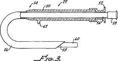
針アクチュエーター22の断面図が示されている図3に移る。針アクチュエーターは近接端部52と遠位末端部54を有する空洞円筒管50である。管50は空洞の針26と遠位末端部54で接合しており、近接端部52にスタイレット56を受ける小さい開口部を有している。針26は組織を穿刺するのに適した尖った針先58を有しており、針先はスタイレット56を受ける大きさの内径を有している。図3にはスタイレット56が示されているが、スタイレットが含有される必要はない。スタイレットは、近接端部に末端プラグ59を、そして遠位末端部には通常丸い先端60を有して示されている。管50はまた、遠位末端部54に向かってその外径に位置するロッキングタブ62を有している。このロッキングタブ62は内視鏡100に対する針アクチュエーター22の動きを固定するのに使用される。タブ62は、ハンドル本体30の内径に位置するロッキング溝45と接合するよう設計されている。
Turning to FIG. 3, where a cross-sectional view of the
図4〜6に、カテーテル装置アクチュエーター20がより詳細に示されている。カテーテル装置アクチュエーター20は、カテーテル装置24の動きをコントロールし、カテーテル装置24を内視鏡中心軸に沿って動かすことが可能である。図4に示すように、カテーテル装置アクチュエーター20が筐体70を有している。筐体70は遠位末端部と近接端部を有する空洞円筒管である。遠位末端部はシース24と接合するため、やや先細りになっている。本体は、針本体管50のロッキングタブ62を受容する大きさの縦長の穴72を有している。穴72は、筐体70の近接端部から筐体70の遠位末端部までの約4分の3の長さにわたって連続している。本体の近接端部は先端キャップ75のねじを受容するねじ73を有している。キャップ75は、筐体70の内部の空洞内に位置する針アクチュエーターが、筐体から外に出るのを防止する。しかし、先端キャップは、必要に応じて、針アクチュエーターが組織の拡張筋から引き出されるよう取り外すことができる。キャップは中心に丸い穴を有しており、針アクチュエーター22の近接部52とスタイレット28を筐体70の外に延伸させることを可能にする。
The
カテーテル装置24は遠位末端部から近接端部に伸びる二つの内部管腔を有している。本カテーテル装置24はプラスチックポリマー、スプリング・コイル、シリコーン、テフロン加工の管類など、様々な素材から構成されることができる。主となる管腔77はより大きく、針本体26を受容するよう設計されており、また、針の除去時には、1本の0.035インチの誘導ワイヤーまたは最大2本の0.021インチの誘導ワイヤーが適合するのに充分な大きさである。小さい方の管腔76は拡張バルーンを膨張および収縮するためにカテーテル装置の遠位末端部に接着されている。拡張バルーン25の端は、カテーテル装置の先端21に直接に近接して設置されることが可能である。バルーンの遠位末端部はカテーテル装置24の遠位末端部の間に、カテーテル装置の遠位末端部から最大で4cmのところに設置され得ることがより望ましい。バルーン25は直径5〜10mmに膨張されることが望ましく、長さは3〜6cmであると効果的である。しかし、バルーンの長さおよび直径は様々なものが使用可能である。カテーテル装置はまた、カテーテル装置24が単一管腔を有しかつ膨張端子が無い場合には、拡張バルーンなしで構成されることもできる。
カテーテル装置アクチュエーター20はシースの管腔に合致する二つの管腔を有している。図5に示すように、針管腔79は筐体70の全体の長さにわたって連続しており、シースの主管腔77に接続されている。膨張管腔78は筐体70の遠位末端部から伸び、筐体70の近接端部の前で終わる。この管腔はシースの小管腔76とつながっている。筐体70は、カテーテル装置アクチュエーターに接着し、かつ外側の端に膨張注射器と接合するルアー・コネクター84を有する、膨張端子83を有している。膨張端子83はバルーン25を膨張および収縮するのに使用される。膨張管腔78の近接部は、膨張管腔78の近接端部からの膨張した液体の漏出を防ぐため、栓81で閉鎖されている。
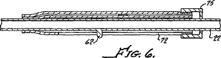
針アクチュエーター22とカテーテル装置アクチュエーター20が組み立てられて、図6に示されている。この図では、カテーテル装置アクチュエーター20の内部での、針アクチュエーター22の設置の仕方がわかる。また、穴72の中に位置し、かつ筐体70の壁を通って突出しているロッキングタブ62が示されている。また、筐体70の空洞の中に針アクチュエーターを保持する先端キャップ75も示されている。
The
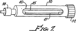
ハンドル本体は図7に、より詳細に示されている・円筒形の本体30は開口部40を本体の中に有している。開口部は本体の中心部に位置し、本体30の内側に開く。開口部40は本体30に、カテーテル装置アクチュエーターの膨張端子83を受容するよう形成されている。カテーテル装置アクチュエーター20は本体30の内径に沿ってスライドし、開口部は、カテーテル装置アクチュエーター20が前進および本体30の内部でわずかに回転しながらの後退が可能になるよう、膨張端子83にクリアランスを与える。本体の内壁表面は、針アクチュエーター22のロッキングタブ62との結合に使用されるロッキング溝45を有している。溝45は本体30の近接端部から本体の遠位部まで約4分の3にわたって続いている。針アクチュエーター管50のロッキングタブ62での外径“x”は円筒形の本体30の溝で測定された内径“y”よりやや小さくなっていることが、図8で、ハンドル本体および針アクチュエーターの横断面図によって示されている。この図では、明確にするためシースアクチュエーターは除外されている。溝45の深さは、ロッキングタブ62が自由に動けるようなクリアランスを有しているが、溝45から飛び出すほどのクリアランスではない。ロッキングタブ62は、カテーテル装置アクチュエーター20内部での針アクチュエーター22の前進および後退時に、本体30の溝をスライドする。
The handle body is shown in more detail in FIG. 7. The
溝はロッキング斜面47によってその長さに沿って遮断される。ロッキング斜面47(図9〜10により詳細に図示)は溝45に沿って位置している。ロッキング斜面47の深さは半径方向によって変化する。溝45のロッキング傾斜47の入口では、ロッキング傾斜47の深さは溝45の底部と同じであるが、壁の側面は徐々に傾斜してハンドル本体30の内径に接触する。ロッキングタブ62は溝45に沿って前進および後退し、針アクチュエーター本体22がわずかに回転するならば、ロッキングタブもロッキング溝45から動いてロッキング傾斜47に移動する。ロッキング47は、ロッキングタブ62が内視鏡100の縦軸に沿って自由に動くことを制限する。針アクチュエーター本体22がわずかに回転するならば、ロッキングタブ62は先細りの側面に沿って移動し、かつ、前進移動がクリアランスの除去とともにいずれは止められるよう先細りの側壁に作用する。この地点で、ロッキングタブ62は、内視鏡の中心軸に対して原則的に固定されて保持される。この位置でタブ62はロッキング部として作用する。針アクチュエーター本体22がまださらに回転する場合は、ロッキングタブ62は先細りの側壁に沿って移動を続け、急停止とともに側壁に沿って押し込まれる。この方法では、手術者がカテーテル装置アクチュエーター20の動きは許容したまま、内視鏡100に対する針アクチュエーター22の横の動きを固定することが可能である。手術者はまた、体感する抵抗の程度に関してのコントロールもできる。わずかな回転は摩擦抵抗を高めるが、それでも針アクチュエーター本体22は内視鏡の軸に沿って動かされることが可能である。さらなる回転は、針アクチュエーター本体22が固定されるまで、摩擦抵抗をさらに高める。
The groove is blocked along its length by a locking ramp 47. A locking ramp 47 (shown in more detail in FIGS. 9-10) is located along the
図1の装置組立図は、様々な部分の互いの組み立て方を示している。矢印はアクチュエーターが移動する方向を示している。針アクチュエーター22は、矢印Bにしたがって、内視鏡の縦軸に沿って前進または後退が可能であり、必要に応じて空洞体器官または組織の内部で針に同じ動きを伝える。針アクチュエーターは10cm以内で移動され得ることが望ましい。針アクチュエーターは4cm〜8cmの間で移動され得ることが、さらに望ましい。同様に、カテーテル装置アクチュエーター20は、矢印Aにしたがって、内視鏡の縦軸に沿って前進または後退が可能であり、必要に応じて空洞体器官または組織の内部でカテーテル装置24に同じ動きを伝える。カテーテル装置アクチュエーター20は10cm以内で移動され得ることが望ましい。カテーテル装置アクチュエーター20は4cm〜8cmの間で移動され得ることが、さらに望ましい。どちらのアクチュエーターの動きも、もう一方のアクチュエーターが動いている間、内視鏡に対して固定されることが可能である。針アクチュエーター20は、矢印Cにしたがって回転することにより固定され、必要に応じて、ロッキング傾斜47に沿ってロッキングタブ62を動かす。カテーテル装置アクチュエーター22は、ハンドル本体30の近接端部31に設置されたキャップ32を留めることによって、位置を固定される。本装置は、手術者が針26とカテーテル装置24の位置と動きを容易にコントロールできるようにする。この方法では、針26が先に前進させることが可能で、その位置を固定されてからカテーテル装置24が、針が同時に組織の中でさらに移動することを懸念せずに、針の上を前進させることが可能である。この方法は、処置をより安全に簡単にするものになり得る。
The device assembly diagram of FIG. 1 shows how the various parts are assembled together. The arrow indicates the direction in which the actuator moves. The
図11に本装置10の他の実施例を示す。この実施例では、装置10はカテーテル装置24、および22ゲージまたは23ゲージの穴を削った針26とともに、ハンドル115カテーテル装置アクチュエーター120、針アクチュエーター122を使用する。前実施例同様に、針26の内部管腔にはスタイレット28が充填されている。
FIG. 11 shows another embodiment of the apparatus 10. In this embodiment, the device 10 uses a
ハンドル115は、カテーテル装置120または針アクチュエーター122もしくは両方が操縦される間、医師が片手で装置10を支えて保持するよう設計されている。各場合で、本実施例のカテーテル装置24および針26は、単一ユニットとして、またはそれぞれ個別に機能するであろうことが予測される。カテーテルアクチュエーター120および針アクチュエーター122は同時にまたは連続して操作される可能性があるためである。ハンドル115はカテーテル装置24と針26同軸システムの動作管理を一箇所に統合するのに特に有効である。カテーテル装置24および針26のアクチュエーターはハンドル115の一部を構成している。手術者はこれらのアクチュエーターからカテーテル装置24および針26を動かすことができる。
The
図12に示されるように、ハンドル115は空洞円筒管で近接端部が開口して製作された本体130を有している。遠位末端部133は、カテーテル装置が通過する大きさになっている片方の開口部を除いて、基本的に閉鎖している。本体130はカテーテル装置および針のアクチュエーターの筐体として機能しており、プラスチック、金属または他の適合する素材で構成されることができる。本体130は近接端部131に、キャップ132に結合するように設計されたねじ134でねじ留めされる。キャップ132は本体130と本体130の近接端部31を部分的に閉鎖してねじ留めされるよう設計されている。本体は、本体の軸と平行に走りねじ134と垂直になる、一つかそれ以上の切り込み136を有している。これらの切り込み136は、キャップ132のねじ留め時に圧縮接続として機能するよう設計されているねじ134と交差する。キャップ132が本体にねじ留めされている間、キャップ132は本体の近接端部131の内径を減少させる効果がある。
As shown in FIG. 12, the
ハンドル115は、カテーテル装置24または針26のいかなる動作も内視鏡の逆の動作を同時に生じさせないために、内視鏡100と連結している。ハンドルの遠位末端部133のコネクター138は、内視鏡本体の対応するコネクターと接合する。コネクター138はルアー・コネクターであることが望ましいが、内視鏡とハンドルが連結され得るコネクターであれば、可能である。針26は針アクチュエーター122の内部およびカテーテル装置24内部の内径をスライドする大きさである。 針26の近接端部は針に接着されたハブ138を有しており、ハブ138は針アクチュエーター122の近接端部に適合するコネクター139に連結するよう設計されている。このハブ138は、アクチュエーターによる針の作動のための、針アクチュエーター122への針の接着を促進する。ハブ138は、針26を針アクチュエーター122と本体130から取り外すため、コネクター139および針アクチュエーター122から切断されることが可能である。針アクチュエーター122はカテーテルアクチュエーター120の外側を、そしてその後本体130内部の内径をスライドする大きさである。カテーテル装置および針のアクチュエーターと本体130は接合機構として互いに機能している。
The
針アクチュエーター122は図13に、より詳細に示されている。針アクチュエーター122は空洞円筒管150である。遠位末端部は開口されており、近接端部はコネクター139で終わっている。針アクチュエーター122の内径は、カテーテル装置120の外径に沿って収まる大きさである。通常、二つの直径の寸法は、カテーテル装置120が管150の内部で自由に、しかし異常な揺れがなく滑らかに移動できるよう、互いに接近している。管150は、管150の長いほうの長さに沿って縦方向に走る、ひとつかそれ以上の切り込み151を有している。切り込みは、管150の外径から管150の壁を通り、内径まで続いている。ひとつ以上の切り込みを利用する場合は、切り込み151は管150の円周と対称に配列されなければならない。
カテーテル装置120アクチュエーターは図14〜16に、より詳細に示されている。カテーテル装置120アクチュエーターは、カテーテル装置24の動きをコントロールし、カテーテル装置24を内視鏡100の中心軸に沿って動かすことが可能である。図14に示すように、カテーテル装置アクチュエーター120は、筐体160、ホルダー162、およびホルダー162の反対側にある膨張端子164を有している。前記実施例と同様に、カテーテルアクチュエーター120と連結するカテーテル装置24は、遠位末端部から近接端部に伸びる二つの内部管腔を有する。主となる管腔77はより大きく、針本体26を受容するよう設計されており、また、針の除去時には、0.035インチの誘導ワイヤーが1本または0.021インチの誘導ワイヤーが最大2本まで適合するのに充分な大きさである。小さい方の管腔76は、カテーテル装置24の遠位末端部に接着されている拡張バルーン25を膨張および収縮するために使用されることが可能である。カテーテル装置24は、カテーテル装置24が単一管腔を有し、かつ膨張端子が無い場合、拡張バルーンなしで構成されることもできる。
The
膨張管腔168は、カテーテル装置24の小管腔およびカテーテルアクチュエーター120の膨張端子164と流動的に連通する。膨張端子164は膨張注射器の接着に適合する外端に、ルアー・コネクター166を有している。膨張端子164はバルーン25を膨張および収縮するために使用される。管腔168の近接部は、膨張管腔168の近接端部から膨張した液体の漏出を防ぐため、栓170で閉鎖されている。針管腔169はカテーテル装置24の大管腔77に接続しており、針26を受けるため両端が開口している。ホルダー162は筐体160と連結しており、手術者は、カテーテルアクチュエーター120をハンドル115に沿って前進および後退させるのに使用する。ホルダー162は針アクチュエーター本体150とハンドル115にわたって延伸するのに充分な長さがある。ホルダー162と膨張端子164が図示されているが、これらの機能をひとつの装置に結集することが可能である。この別の実施例では、膨張端子164は流体流入箇所として、また、手術者がカテーテルアクチュエーターを操作するのに使用できるホルダーとしての役割を持つ。この実施例はホルダー162を 除去し、管150の切り込み151を一つのみにすることもできる。この実施例は操作がより簡単で、より低廉になり得る。筐体の近接端部171はカテーテルアクチュエーターの前進時に、筐体のいくつかの部分を本体115内で常に固定を守るために、必要に応じて長くなり得る。筐体は針アクチュエーター本体122の内部にぴったり納まる大きさである。
The
カテーテルアクチュエーター120と針アクチュエーター122が組み立てられて、図15に示されている。この図では、針アクチュエーター122がカテーテルアクチュエーター120の外側に設置され、しかし針26はカテーテルアクチュエーター120の内側に設置される方法が示されている。ホルダー162および膨張端子164は、針アクチュエーター122の切り込み151を通って突出して図示されている。図16Aは、カテーテルアクチュエーター120のAからAまでの部分の、針アクチュエーター122を除いた横断面図を示す。図16Bは、カテーテルアクチュエーター120のAからAまでの部分の、針アクチュエーター122を設置した横断面図を示す。切り込み151は、ホルダー162およびこれらの切込みを通って突出する膨張端子164とともに図示されている。針26とスタイレット28は管腔169の中心に示されている。図16Cは、同じカテーテルアクチュエーター120のAからAまでの部分の、針アクチュエーター122およびホルダー162を除いた横断面図を示す。この実施例では、膨張端子164は膨張液体の導入部分およびホルダーとして機能し、針アクチュエーター本体150には切り込み151が一つのみである。
The
図11および図12に、円筒形の本体115が本体主部に二つの開口部を有して示されている。これらの開口部は通常、180度の間隔で本体の中心部に設置される。開口部は、本体115にホルダー162と膨張端子164を受容するよう形成されている。カテーテルアクチュエーター120は本体115の内径に沿ってスライドし、開口部はカテーテル装置アクチュエーター120が前進して本体115の内部でわずかに回転しながら退避できるよう、膨張端子164にクリアランスを与える。開口部(180度離れて配置される)の片側に沿って、はホルダー162および膨張端子164を接合させるために使用される一連のロッキング部182がある。カテーテルアクチュエーターの前進時に、ホルダー162および膨張端子164は、本体115の、対する開口部に沿って遠位方向に動く。ホルダー162および膨張端子164は、ホルダー162および膨張端子164を受容する大きさのこれらロッキング部182の一つの中にホルダーおよび膨張端子が移動するよう、わずかに放射状に回転することが可能である。ホルダー162および膨張端子164がロッキング部182に挿入されると、本体115に沿った遠位末端方向への動きが阻止される。この方法では、手術者は、先端が体内で正しく位置するまでカテーテル装置24を前進させ、そして内視鏡100に対してカテーテル装置24の位置を固定することが可能である。
11 and 12, a cylindrical
図11に装置組立図が示されており、またこの図は様々な部分の組み立て方を図示している。 矢印はアクチュエーターが移動する方向を示している。図示されるように、針26およびスタイレット28はDの方向に移動する。針26はハブ138およびコネクター139を使用して針アクチュエーター122に連結しており、 針26および針アクチュエーター122は本体115の内壁に沿ってEの方向に、単一ユニットのように動かすことが可能である。これは、コネクター139またはアクチュエーター本体の外側を保持し、またハンドル115を支えて遠心に動かすことによって完遂される。同様に、カテーテルアクチュエーター120は、ホルダー162を使用することによって、図に示されるF方向に、針アクチュエーター122の内壁に沿って進められることが可能である。ホルダー162または膨張端子164に加えられるわずかな回転運動(図示せず)は、これらを穴の端に沿って配置されたロッキング穴182のいずれかの部分の中へ移動させる。針アクチュエーター122は10cm以内で移動され得ることが望ましい。 針アクチュエーター122は4cm〜8cmの間で移動され得ることが、さらに望ましい。カテーテル装置アクチュエーター120は10cm以内で移動され得ることが望ましい。カテーテル装置120アクチュエーターは4cm〜8cmの間で移動され得ることが、さらに望ましい。どちらのアクチュエーターの動きも、もう一方のアクチュエーターが動いている間、内視鏡に対して固定されることが可能である。針アクチュエーター122の動きは、キャップ32を硬く留めることによって、内視鏡に固定されることが可能である。これは、針アクチュエーター122の空洞円筒管150に作用する、本体115の内径の減少の要因となる。カテーテルアクチュエーター120の動きは、前述のロッキング穴のひとつにホルダー162が回転して入ることにより、内視鏡に固定されることが可能である。
FIG. 11 shows an assembly drawing of the apparatus, and this figure shows how to assemble various parts. The arrow indicates the direction in which the actuator moves. As shown,
図17〜21に示すように、内臓管腔104と目標となる管腔組織102の間のパイプの作成は、本システムを使用して実行され得る。この処置では、スタイレットが充填された針26およびカテーテル装置24は、内視鏡のワーキングルーメンの中に導入された装置の一部になっている。第一の実施例を参照に、ハンドル15はコネクター38を使用して内視鏡のワーキング・チャンネルの外側に固定されている。針26が穿刺部に挿入されると、針は最大で8cm進められ、内臓壁を通り抜け、目的となる管腔組織の中に入る(図20)。目的の管腔組織内で、スタイレット28は除去され、吸引の適用または造影剤の注入が目標の管腔の中に確実になされるよう、透視のもとで行われることが可能である。図17〜19に示されている目標の場所は、胃壁104の反対側の偽性嚢胞空洞120であるが、この方法には人体の他の多くの場所が含まれる。針26はその後、針アクチュエーター22をロッキングタブ62がロッキング傾斜47の中に移動して針アクチュエーター22が固定されるまで回転することによって、位置を固定される。カテーテル装置は次に組織壁を通って固い針に沿って進められる。目標の管腔に対するカテーテル装置24の位置は、X線不透過マーカー96および97を蛍光透過使用によって可視化すること、またはスタイレットを除外した針の近接端部にX線不透過染料を注入することによって、決定される。実施例に示されるように、 X線不透過マーカー96および98は、拡張バルーンの各端に位置する。組織の、対象とする位置では、カテーテル装置24はハンドル本体30のキャップ3を押し回すことによって位置を固定されることが可能である。カテーテル装置に拡張バルーン25がその遠位末端部に接着されている場合、バルーンは膨張端子83を使用して、液体またはガス膨張液で膨張され得る。膨張されたバルーンは内臓と目標の器官の間に通路を作成することが可能である。膨張されたバルーン25はまた、針26が誘導ワイヤーに変換できるよう、シース24をしっかりと固定させる。針26は、1本の0.035"または2本の0.021"誘導ワイヤーがカテーテル装置24を通って目標の管腔に導入され得るよう、引き出すことが可能である。バルーン25は収縮され、カテーテル装置24は少なくともひとつ以上の誘導ワイヤーが残る、拡張されたパイプの中から取り外されることが可能である。
As shown in FIGS. 17-21, the creation of a pipe between the
他の方法として、装置は、組織の中への誘導ワイヤーの配置を促進するカテーテルをしっかり固定するものとして機能することが可能である。一例として、図21に示されるように、この処置は誘導ワイヤーを体内の管路99の中に配置するために使用されることが可能である。管路は胆管または膵管であることが望ましい。針26は、超音波内視鏡検査のもとで、十二指腸または胃から内臓壁を通って胆管または膵管の中へ、鋭い針先を使用して進められる。 そしてカテーテル装置24は管路99の中へ、針の上を進む。管路99の中では、拡張バルーン25が 任意で膨張される。これは管路99内でシステムに追加的な固定を与え、針26が後退されるときに引き出されることを防ぐために提供される。針26が取り外されると0.035"誘導ワイヤーがカテーテル装置を通して管路99の中に安全に配置され、バルーン25が収縮されるとカテーテル装置24は引き出されることができる。
Alternatively, the device can function as a secure anchor for the catheter that facilitates placement of the guide wire into the tissue. As an example, as shown in FIG. 21, this procedure can be used to place a guide wire in a
さらに別の方法において、あらかじめ湾曲された、または先端が操縦可能なカテーテルが、バルーン装置の代わりに、スタイレットが充填された針の上に設置されることが可能である。湾曲されたカテーテルの先端は、カテーテルの先端を別の方向に操縦するのに便利である。一例として、この工程処置は、誘導ワイヤーを順行性の位置から胆管または膵管の中に配置するのに使用されることが可能である。針26は、超音波内視鏡検査のもとで、十二指腸または胃から内臓壁を通って胆管または膵管の中へ、鋭い針先を使用して進められる。そしてカテーテル装置が管路の中へ針の上を進む。その後、針は0.035”誘導ワイヤーと交換される。
In yet another method, a pre-curved or tip steerable catheter can be placed on a stylet filled needle instead of a balloon device. A curved catheter tip is convenient for steering the catheter tip in another direction. As an example, this process procedure can be used to place a guide wire into the bile duct or pancreatic duct from an antegrade position. The
付随の図は本発明の更なる理解を提供し、本明細書の一部に組み込まれ、構成要素となっている。図は、本発明の実施例を記述と共に例証し、本発明の原理の説明を供する。図において、
10.装置
15.ハンドル
20.カテーテル装置アクチュエーター
21.カテーテル装置先端
22.針アクチュエーター
24.カテーテル装置、シース
25.膨張バルーン
26.針
28.スタイレット
30.本体
31.近接端部
32.キャップ
33.遠位末端部
34.ねじ
36.切り込み
38.コネクター
40.開口部
45.ロッキング溝
47.ロッキング斜面
50.(空洞円筒)管
52.近接端部
54.遠位末端
56.スタイレット
58.針先
59.末端プラグ
60.(丸い)先端
62.ロッキングタブ
70.筐体
72.(縦長の)穴
73.ねじ
75.キャップ
76.管腔(小)
77.管腔(大)
78.膨張管腔
79.針管腔
81.栓
83.膨張端子
84.ルアー・コネクター
100.内視鏡
115.ハンドル
120.カテーテル装置
122.針アクチュエーター
130.本体
131.遠位末端部
132.キャップ
133.近接端部
143.ねじ
136.切り込み
138.コネクター、ハブ
139.コネクター、ハブ
150.(針アクチュエーターの)管
151.切り込み
160.筐体
162.ホルダー
164.膨張端子
166.ルアー・コネクター
168.膨張管腔
169.(針の)管腔
170.栓
171.近接端部
10.
77. Lumen (Large)
78. Inflation lumen 79. Needle lumen 81. Stopper 83. Expansion terminal 84.
Claims (9)
カテーテル装置アクチュエーターおよび針アクチュエーターを格納するハンドル部であって、該ハンドル部は、接続部を有し、該接続部は、該ハンドル部を取り外し可能で内視鏡の近接端部に取り付け、該ハンドル部と該内視鏡との間の相対的移動を防止するように構成され、該カテーテル装置アクチュエーターは、細長いカテーテル装置の近接端部に連結され、該カテーテル装置は、遠位末端部、膨張管腔、および直通管腔を有し、該針アクチュエーターは、該ハンドル部および該内視鏡に対する該針アクチュエーターの位置を固定するように構成されたロッキング機構を有している、ハンドル部、
該カテーテル装置の遠位末端部の近くに配置された拡張バルーンであって、該バルーンの膨張を可能にするために、該膨張管腔と流動的に連通している拡張バルーン、ならびに、
該カテーテル装置の直通管腔に設置された細長い針であって、該針は、近接端部および遠位末端部を有し、該針の近接端部に該針アクチュエーターが連結されている、細長い針、
を含み、
該針アクチュエーターは、該ハンドル部および該内視鏡に対して移動することにより、該カテーテル装置の直通管腔の中で該針をスライド可能に移動させるように構成され、
該カテーテル装置アクチュエーターは、該ハンドル部、該内視鏡、および該針に対して移動することにより、該内視鏡のワーキング・チャンネルの中で該カテーテル装置をスライド可能に移動させるように構成され、
該針アクチュエーターのロッキング機構は、該針および該内視鏡が静止したままで、該カテーテルが該針の上を前進または後退されることができるように固定されることが可能であり、
該針は、該カテーテルとは別個に前進または後退されることが可能である、
装置。 A device configured to be inserted into a hollow body organ through an endoscopic working channel having a central axis, the device comprising:
A handle portion for storing a catheter device actuator and needle actuator, the handle portion includes a connection portion, the connection portion is attached to the proximal end of the endoscope is removable the handle portion, the handle is configured to prevent relative movement between the parts and the endoscope, the catheter device actuator is coupled to the proximal end of the narrow long catheter device, the catheter device, the distal end portion, the expansion A handle portion having a lumen and a direct lumen, the needle actuator having a locking mechanism configured to fix the position of the needle actuator relative to the handle portion and the endoscope;
An dilatation balloon disposed near the distal end of the catheter device, wherein the dilatation balloon is in fluid communication with the dilatation lumen to allow inflation of the balloon; and
An elongate needle disposed in a direct lumen of the catheter device, the needle having a proximal end and a distal end , the needle actuator being coupled to the proximal end of the needle. needle,
Including
The needle actuator is configured to slidably move the needle within the direct lumen of the catheter device by moving relative to the handle portion and the endoscope;
The catheter device actuator is configured to slidably move the catheter device within a working channel of the endoscope by moving relative to the handle portion, the endoscope, and the needle. ,
The locking mechanism of the needle actuator can be fixed so that the needle and the endoscope remain stationary and the catheter can be advanced or retracted over the needle;
The needle can be advanced or retracted separately from the catheter;
apparatus.
カテーテル装置および針を含み、
該カテーテル装置の近接端部および該針の近位端部はハンドルに連結され、
該カテーテル装置および該針は該内視鏡のワーキング・チャンネル内部で前後に動くことが可能であり、該カテーテル装置または該針の位置は該内視鏡に対して固定されることが可能であり、
該カテーテル装置が、膨張管腔と、該カテーテル装置の遠位末端部に連結され、該膨張管腔と流動的に連通している拡張バルーンとを含み、該針は、該カテーテルとは別個に前進または後退されることが可能である、
装置。 A device inserted into the cavity body organ through the working channel of the endoscope,
Including a catheter device and a needle,
The proximal end of the proximal end and needle of the catheter apparatus is connected to the handle,
The catheter device and needle is capable of moving Kukoto back and forth within the working channel of the endoscope, the position of the catheter device or the needle is capable of being fixed to the endoscope Yes ,
The catheter device, the inflation lumen is coupled to the distal end of the catheter device, seen including a dilatation balloon in fluid fluid communication with the inflation lumen, the needle is separate from the catheter Can be moved forward or backward,
apparatus.
該内視鏡のワーキング・チャンネル内で別個に動くことが可能であるカテーテル装置および針を含み、
該カテーテル装置の近接端部および該針の近接端部はハンドルに連結し、
該ハンドルは、該内視鏡に該ハンドルを固定する一つ以上のロッキング部を有し、
該カテーテル装置は、該内視鏡に該カテーテル装置を固定する一つ以上のロッキング部を有し、そして該針は、該内視鏡に該針を固定する一つ以上のロッキング部を有し、
該カテーテル装置が、膨張管腔と、該カテーテル装置の遠位末端部に連結され、該膨張管腔と流動的に連通している拡張バルーンとを含む、
装置。 A device inserted into the cavity body organ through the working channel of the endoscope,
Includes a catheter device and needle can be moved separately in the endoscope working within channels,
The proximal end of the catheter device and the proximal end of the needle are coupled to a handle;
The handle has one or more locking portions for fixing the handle to the endoscope;
The catheter device has one or more locking portions that secure the catheter device to the endoscope, and the needle has one or more locking portions that secure the needle to the endoscope ,
The catheter device includes an inflation lumen, are connected to the distal end of the catheter device, and a dilatation balloon in fluid fluid communication with the inflation lumen,
apparatus.
内視鏡、
該内視鏡に連結される取り外しが可能なハンドル、
該内視鏡のワーキングルーメンに設置された細長いカテーテル装置、
該カテーテル装置のワーキングルーメンに設置された細長い針、
を含み、
該カテーテル装置の近接端部は、移動ができるよう該ハンドルに連結され、
該針の近接端部は、移動ができるよう該ハンドルに連結され、
そして該ハンドルは、該内視鏡の軸に沿って該カテーテル装置または該針の移動がコントロールできるアクチュエーターを有し、
該カテーテル装置が、膨張管腔と、該カテーテル装置の遠位末端部に連結され、該膨張管腔と流動的に連通している拡張バルーンとを含み、該針は、該カテーテルとは別個に前進または後退されることが可能である、
システム。 A system for forming a tissue passage in the wall of the cavity body organ,
Endoscope,
A detachable handle connected to the endoscope;
An elongate catheter device installed in the working lumen of the endoscope;
An elongate needle installed in the working lumen of the catheter device;
Including
A proximal end of the catheter device is coupled to the handle for movement;
The proximal end of the needle is connected to the handle for movement;
The handle has an actuator that can control movement of the catheter device or the needle along the axis of the endoscope,
The catheter device, the inflation lumen is coupled to the distal end of the catheter device, seen including a dilatation balloon in fluid fluid communication with the inflation lumen, the needle is separate from the catheter Can be moved forward or backward,
system.
Applications Claiming Priority (3)
| Application Number | Priority Date | Filing Date | Title |
|---|---|---|---|
| US63425404P | 2004-12-08 | 2004-12-08 | |
| US60/634,254 | 2004-12-08 | ||
| PCT/US2005/044158 WO2006062996A2 (en) | 2004-12-08 | 2005-12-07 | Method and apparatus for performing needle guided interventions |
Publications (3)
| Publication Number | Publication Date |
|---|---|
| JP2008522741A JP2008522741A (en) | 2008-07-03 |
| JP2008522741A5 JP2008522741A5 (en) | 2009-03-05 |
| JP5111112B2 true JP5111112B2 (en) | 2012-12-26 |
Family
ID=36578497
Family Applications (1)
| Application Number | Title | Priority Date | Filing Date |
|---|---|---|---|
| JP2007545575A Expired - Fee Related JP5111112B2 (en) | 2004-12-08 | 2005-12-07 | Device for performing needle-guided therapy |
Country Status (4)
| Country | Link |
|---|---|
| US (2) | US8328837B2 (en) |
| EP (2) | EP1858396B1 (en) |
| JP (1) | JP5111112B2 (en) |
| WO (1) | WO2006062996A2 (en) |
Families Citing this family (103)
| Publication number | Priority date | Publication date | Assignee | Title |
|---|---|---|---|---|
| US8425539B2 (en) | 2004-04-12 | 2013-04-23 | Xlumena, Inc. | Luminal structure anchoring devices and methods |
| US20050228413A1 (en) * | 2004-04-12 | 2005-10-13 | Binmoeller Kenneth F | Automated transluminal tissue targeting and anchoring devices and methods |
| EP1858396B1 (en) | 2004-12-08 | 2019-02-06 | Boston Scientific Scimed, Inc. | Apparatus for performing needle guided interventions |
| US8784437B2 (en) * | 2005-06-09 | 2014-07-22 | Xlumena, Inc. | Methods and devices for endosonography-guided fundoplexy |
| US8777967B2 (en) * | 2005-06-09 | 2014-07-15 | Xlumena, Inc. | Methods and devices for anchoring to tissue |
| US9162037B2 (en) | 2005-07-06 | 2015-10-20 | Vascular Pathways, Inc. | Intravenous catheter insertion device and method of use |
| US8784336B2 (en) | 2005-08-24 | 2014-07-22 | C. R. Bard, Inc. | Stylet apparatuses and methods of manufacture |
| US8388546B2 (en) | 2006-10-23 | 2013-03-05 | Bard Access Systems, Inc. | Method of locating the tip of a central venous catheter |
| US7794407B2 (en) | 2006-10-23 | 2010-09-14 | Bard Access Systems, Inc. | Method of locating the tip of a central venous catheter |
| EP2150304B1 (en) | 2007-05-07 | 2010-12-01 | Vascular Pathways Inc. | Intravenous catheter insertion and blood sample devices and method of use |
| US9405823B2 (en) * | 2007-07-23 | 2016-08-02 | Nuance Communications, Inc. | Spoken document retrieval using multiple speech transcription indices |
| US8781555B2 (en) | 2007-11-26 | 2014-07-15 | C. R. Bard, Inc. | System for placement of a catheter including a signal-generating stylet |
| US9521961B2 (en) | 2007-11-26 | 2016-12-20 | C. R. Bard, Inc. | Systems and methods for guiding a medical instrument |
| US10524691B2 (en) | 2007-11-26 | 2020-01-07 | C. R. Bard, Inc. | Needle assembly including an aligned magnetic element |
| US8849382B2 (en) | 2007-11-26 | 2014-09-30 | C. R. Bard, Inc. | Apparatus and display methods relating to intravascular placement of a catheter |
| ES2465915T3 (en) | 2007-11-26 | 2014-06-09 | C.R. Bard, Inc. | Integrated system for intravascular catheter placement |
| US9649048B2 (en) | 2007-11-26 | 2017-05-16 | C. R. Bard, Inc. | Systems and methods for breaching a sterile field for intravascular placement of a catheter |
| US10751509B2 (en) | 2007-11-26 | 2020-08-25 | C. R. Bard, Inc. | Iconic representations for guidance of an indwelling medical device |
| US10449330B2 (en) | 2007-11-26 | 2019-10-22 | C. R. Bard, Inc. | Magnetic element-equipped needle assemblies |
| US20090143760A1 (en) | 2007-11-30 | 2009-06-04 | Jacques Van Dam | Methods, Devices, Kits and Systems for Defunctionalizing the Gallbladder |
| US8454632B2 (en) | 2008-05-12 | 2013-06-04 | Xlumena, Inc. | Tissue anchor for securing tissue layers |
| US20090281379A1 (en) * | 2008-05-12 | 2009-11-12 | Xlumena, Inc. | System and method for transluminal access |
| WO2010022370A1 (en) | 2008-08-22 | 2010-02-25 | C.R. Bard, Inc. | Catheter assembly including ecg sensor and magnetic assemblies |
| US8437833B2 (en) | 2008-10-07 | 2013-05-07 | Bard Access Systems, Inc. | Percutaneous magnetic gastrostomy |
| US9278019B2 (en) | 2009-04-03 | 2016-03-08 | Metamodix, Inc | Anchors and methods for intestinal bypass sleeves |
| US9173760B2 (en) | 2009-04-03 | 2015-11-03 | Metamodix, Inc. | Delivery devices and methods for gastrointestinal implants |
| KR20120008492A (en) | 2009-04-03 | 2012-01-30 | 메타모딕스, 인코포레이티드 | Modular gastrointestinal prostheses |
| US9364259B2 (en) * | 2009-04-21 | 2016-06-14 | Xlumena, Inc. | System and method for delivering expanding trocar through a sheath |
| US20120109277A1 (en) | 2010-10-25 | 2012-05-03 | Keke Lepulu | Apparatus and method for penetrating and enlarging adjacent tissue layers |
| US20100268029A1 (en) * | 2009-04-21 | 2010-10-21 | Xlumena, Inc. | Methods and apparatus for advancing a device from one body lumen to another |
| US8357193B2 (en) | 2009-05-29 | 2013-01-22 | Xlumena, Inc. | Apparatus and method for deploying stent across adjacent tissue layers |
| US20120130417A1 (en) * | 2010-10-25 | 2012-05-24 | Keke Lepulu | Apparatus and method for penetrating and enlarging adjacent tissue layers |
| US20110137394A1 (en) * | 2009-05-29 | 2011-06-09 | Xlumena, Inc. | Methods and systems for penetrating adjacent tissue layers |
| US9901347B2 (en) | 2009-05-29 | 2018-02-27 | Terus Medical, Inc. | Biliary shunts, delivery systems, and methods of using the same |
| US8282667B2 (en) * | 2009-06-05 | 2012-10-09 | Entellus Medical, Inc. | Sinus dilation catheter |
| US9445734B2 (en) | 2009-06-12 | 2016-09-20 | Bard Access Systems, Inc. | Devices and methods for endovascular electrography |
| BRPI1010773B1 (en) | 2009-06-12 | 2021-06-01 | Bard Access Systems, Inc | ADAPTER FOR ENDOVASCULAR ELECTROCARDIOGRAPHY CROSS REFERENCE FOR RELATED ORDER |
| US9532724B2 (en) | 2009-06-12 | 2017-01-03 | Bard Access Systems, Inc. | Apparatus and method for catheter navigation using endovascular energy mapping |
| AU2010271294B2 (en) | 2009-07-10 | 2015-09-03 | Metamodix, Inc. | External anchoring configurations for modular gastrointestinal prostheses |
| US8608687B2 (en) * | 2009-07-31 | 2013-12-17 | Medivity, LLC | Multi-lumen endoscopic accessory and system |
| EP2517622A3 (en) | 2009-09-29 | 2013-04-24 | C. R. Bard, Inc. | Stylets for use with apparatus for intravascular placement of a catheter |
| US9504372B2 (en) | 2009-11-13 | 2016-11-29 | Daniel H. Kim | Intradural endoscope |
| JP2013518676A (en) | 2010-02-02 | 2013-05-23 | シー・アール・バード・インコーポレーテッド | Apparatus and method for locating catheter navigation and tip |
| WO2011140535A1 (en) * | 2010-05-07 | 2011-11-10 | Entellus Medical, Inc. | Sinus balloon dilation catheters and sinus surgury tools |
| US9872971B2 (en) | 2010-05-14 | 2018-01-23 | C. R. Bard, Inc. | Guidewire extension system for a catheter placement device |
| US9950139B2 (en) | 2010-05-14 | 2018-04-24 | C. R. Bard, Inc. | Catheter placement device including guidewire and catheter control elements |
| US11925779B2 (en) | 2010-05-14 | 2024-03-12 | C. R. Bard, Inc. | Catheter insertion device including top-mounted advancement components |
| US8932258B2 (en) | 2010-05-14 | 2015-01-13 | C. R. Bard, Inc. | Catheter placement device and method |
| US10384039B2 (en) | 2010-05-14 | 2019-08-20 | C. R. Bard, Inc. | Catheter insertion device including top-mounted advancement components |
| CA2799360C (en) * | 2010-05-14 | 2018-11-20 | C.R. Bard, Inc. | Catheter placement device and method |
| ES2924130T3 (en) | 2010-05-28 | 2022-10-04 | Bard Inc C R | Apparatus for use with needle insertion guidance system |
| EP2912999B1 (en) | 2010-05-28 | 2022-06-29 | C. R. Bard, Inc. | Apparatus for use with needle insertion guidance system |
| US11123141B2 (en) * | 2010-08-19 | 2021-09-21 | Mayo Foundation For Medical Education And Research | Systems and methods for navigating a catheter and delivering a needle |
| EP2605699A4 (en) | 2010-08-20 | 2015-01-07 | Bard Inc C R | Reconfirmation of ecg-assisted catheter tip placement |
| US8801693B2 (en) | 2010-10-29 | 2014-08-12 | C. R. Bard, Inc. | Bioimpedance-assisted placement of a medical device |
| US8690833B2 (en) | 2011-01-31 | 2014-04-08 | Vascular Pathways, Inc. | Intravenous catheter and insertion device with reduced blood spatter |
| EP2678065B1 (en) | 2011-02-25 | 2019-09-11 | C.R. Bard Inc. | Medical component insertion device including a retractable needle |
| USD903101S1 (en) | 2011-05-13 | 2020-11-24 | C. R. Bard, Inc. | Catheter |
| WO2013006817A1 (en) | 2011-07-06 | 2013-01-10 | C.R. Bard, Inc. | Needle length determination and calibration for insertion guidance system |
| US9924938B2 (en) * | 2011-11-07 | 2018-03-27 | C.R. Bard, Inc. | Instruments for delivering transfascial sutures and methods of transfascial suturing |
| US8646921B2 (en) | 2011-11-30 | 2014-02-11 | Izi Medical Products | Reflective marker being radio-opaque for MRI |
| US8661573B2 (en) | 2012-02-29 | 2014-03-04 | Izi Medical Products | Protective cover for medical device having adhesive mechanism |
| WO2013134708A1 (en) * | 2012-03-09 | 2013-09-12 | Clearstream Technologies Limited | Medical balloon with a precisely identifiable portion |
| EP2854654B1 (en) | 2012-05-17 | 2019-11-06 | Boston Scientific Scimed, Inc. | Devices for access across adjacent tissue layers |
| WO2014062728A1 (en) * | 2012-10-18 | 2014-04-24 | C.R. Bard, Inc. | Magnetic element-equipped needle assemblies |
| AU2014207608A1 (en) | 2013-01-15 | 2015-07-30 | Metamodix, Inc. | System and method for affecting intestinal microbial flora |
| US9522254B2 (en) | 2013-01-30 | 2016-12-20 | Vascular Pathways, Inc. | Systems and methods for venipuncture and catheter placement |
| CN105658182B (en) | 2013-02-21 | 2018-07-27 | 波士顿科学国际有限公司 | The device and method for being used to form previous anastomotic |
| EP2777745B1 (en) * | 2013-03-15 | 2018-05-30 | Coloplast A/S | An access sheath |
| WO2014165783A1 (en) * | 2013-04-05 | 2014-10-09 | University Of Iowa Research Foundation | Catheter assembly with segmented stabilization system |
| WO2015120256A2 (en) | 2014-02-06 | 2015-08-13 | C.R. Bard, Inc. | Systems and methods for guidance and placement of an intravascular device |
| CA3191158A1 (en) * | 2014-02-28 | 2015-09-03 | Atricure, Inc. | Pericardial access devices and methods |
| JP6650882B2 (en) * | 2014-05-02 | 2020-02-19 | シー・アール・バード・インコーポレーテッドC R Bard Incorporated | Catheter indwelling device including guidewire and catheter control element |
| JP6311066B2 (en) | 2014-05-28 | 2018-04-11 | ボストン サイエンティフィック サイムド,インコーポレイテッドBoston Scientific Scimed,Inc. | Stent delivery system |
| WO2016037127A1 (en) | 2014-09-05 | 2016-03-10 | C.R. Bard, Inc. | Catheter insertion device including retractable needle |
| US10973584B2 (en) | 2015-01-19 | 2021-04-13 | Bard Access Systems, Inc. | Device and method for vascular access |
| US10362965B2 (en) * | 2015-04-22 | 2019-07-30 | Acclarent, Inc. | System and method to map structures of nasal cavity |
| USD903100S1 (en) | 2015-05-01 | 2020-11-24 | C. R. Bard, Inc. | Catheter placement device |
| MX2017014565A (en) | 2015-05-15 | 2018-03-09 | Bard Inc C R | Catheter placement device including an extensible needle safety component. |
| WO2016210325A1 (en) | 2015-06-26 | 2016-12-29 | C.R. Bard, Inc. | Connector interface for ecg-based catheter positioning system |
| US11000207B2 (en) | 2016-01-29 | 2021-05-11 | C. R. Bard, Inc. | Multiple coil system for tracking a medical device |
| US9622897B1 (en) | 2016-03-03 | 2017-04-18 | Metamodix, Inc. | Pyloric anchors and methods for intestinal bypass sleeves |
| DE202017007388U1 (en) | 2016-05-19 | 2021-02-12 | Metamodix, Inc. | Tools for pyloric anchor recovery |
| WO2018049413A1 (en) | 2016-09-12 | 2018-03-15 | C.R. Bard, Inc. | Blood control for a catheter insertion device |
| WO2018112221A1 (en) * | 2016-12-16 | 2018-06-21 | Boston Scientific Scimed, Inc. | Medical device handles and related methods |
| CN108392294B (en) * | 2017-02-07 | 2020-05-19 | 先健科技(深圳)有限公司 | Puncture device and anchoring device |
| JP6953541B2 (en) | 2017-03-01 | 2021-10-27 | シー・アール・バード・インコーポレーテッドC R Bard Incorporated | Catheter insertion device |
| BR112019019214A2 (en) * | 2017-03-17 | 2020-04-14 | Becton Dickinson Co | midline catheter placement device |
| CN106963516B (en) * | 2017-03-23 | 2019-07-26 | 杭州唯强医疗科技有限公司 | Intracavitary orthotopic fenestration sting device |
| US10561407B2 (en) | 2017-05-05 | 2020-02-18 | Hoya Corporation | Apparatuses and methods for endoscopic tool joints |
| WO2019164838A1 (en) * | 2018-02-20 | 2019-08-29 | Boston Scientific Scimed, Inc. | Puncture devices, and systems and methods for accessing tissue |
| US11389626B2 (en) | 2018-03-07 | 2022-07-19 | Bard Access Systems, Inc. | Guidewire advancement and blood flashback systems for a medical device insertion system |
| JP2021119800A (en) * | 2018-03-19 | 2021-08-19 | オリンパス株式会社 | Insertion aid for endoscope and endoscope system |
| USD921884S1 (en) | 2018-07-27 | 2021-06-08 | Bard Access Systems, Inc. | Catheter insertion device |
| US10992079B2 (en) | 2018-10-16 | 2021-04-27 | Bard Access Systems, Inc. | Safety-equipped connection systems and methods thereof for establishing electrical connections |
| CN114025716A (en) | 2019-02-07 | 2022-02-08 | Nxt生物医疗有限责任公司 | Rivet diverter and deployment method |
| US11659980B2 (en) * | 2019-03-27 | 2023-05-30 | Gyrus Acmi, Inc. | User interface with dual-function control surface for positioning multiple components within a body |
| CA3151126A1 (en) | 2019-08-19 | 2021-02-25 | Becton, Dickinson And Company | Midline catheter placement device |
| US11576647B2 (en) * | 2019-09-30 | 2023-02-14 | Olympus Corporation | Apparatus and method for performing interventional endoscopic ultrasound procedure |
| US11957408B2 (en) | 2020-01-06 | 2024-04-16 | Boston Scientific Medical Device Limited | Medical device locking assemblies and methods of using the same |
| JP2023519567A (en) * | 2020-03-31 | 2023-05-11 | ディブ ウルトラナブ メディカル エルエルシー | Handle assembly for medical devices |
| US20220015787A1 (en) * | 2020-07-16 | 2022-01-20 | Endogear Llc | Grasping Device For Independent Tissue Manipulation During Gastrointestinal Endoscopic Procedures And Methods Of Use |
| CN111938788B (en) * | 2020-08-25 | 2021-07-30 | 哈尔滨医科大学 | Interatrial septum puncture assembly |
Family Cites Families (284)
| Publication number | Priority date | Publication date | Assignee | Title |
|---|---|---|---|---|
| US2127903A (en) | 1936-05-05 | 1938-08-23 | Davis & Geck Inc | Tube for surgical purposes and method of preparing and using the same |
| US3039468A (en) * | 1959-01-07 | 1962-06-19 | Joseph L Price | Trocar and method of treating bloat |
| US3717151A (en) * | 1971-03-11 | 1973-02-20 | R Collett | Flesh penetrating apparatus |
| US3874388A (en) * | 1973-02-12 | 1975-04-01 | Ochsner Med Found Alton | Shunt defect closure system |
| US3970090A (en) | 1975-02-03 | 1976-07-20 | Physio Medics, Inc. | Catheter |
| JPS5835219B2 (en) | 1975-02-04 | 1983-08-01 | 大日本インキ化学工業株式会社 | Seizouhouhou |
| US4173392A (en) | 1977-07-20 | 1979-11-06 | American Hospital Supply Corporation | Glass fiber light guide and method of making the same |
| US4235238A (en) | 1978-05-11 | 1980-11-25 | Olympus Optical Co., Ltd. | Apparatus for suturing coeliac tissues |
| US4587972A (en) | 1984-07-16 | 1986-05-13 | Morantte Jr Bernardo D | Device for diagnostic and therapeutic intravascular intervention |
| US4790813A (en) | 1984-12-17 | 1988-12-13 | Intravascular Surgical Instruments, Inc. | Method and apparatus for surgically removing remote deposits |
| US4608965A (en) | 1985-03-27 | 1986-09-02 | Anspach Jr William E | Endoscope retainer and tissue retracting device |
| US4705040A (en) | 1985-11-18 | 1987-11-10 | Medi-Tech, Incorporated | Percutaneous fixation of hollow organs |
| US5000185A (en) | 1986-02-28 | 1991-03-19 | Cardiovascular Imaging Systems, Inc. | Method for intravascular two-dimensional ultrasonography and recanalization |
| US4920967A (en) | 1986-07-18 | 1990-05-01 | Pfizer Hospital Products Group, Inc. | Doppler tip wire guide |
| US4990139A (en) * | 1986-09-10 | 1991-02-05 | Jang G David | Tandem independently inflatable/deflatable multiple diameter balloon angioplasty catheter systems |
| JPH0755222B2 (en) * | 1986-12-12 | 1995-06-14 | オリンパス光学工業株式会社 | Treatment tool |
| US4917097A (en) | 1987-10-27 | 1990-04-17 | Endosonics Corporation | Apparatus and method for imaging small cavities |
| US5180392A (en) * | 1988-02-01 | 1993-01-19 | Einar Skeie | Anastomotic device |
| US4869263A (en) | 1988-02-04 | 1989-09-26 | Cardiometrics, Inc. | Device and method for measuring volumetric blood flow in a vessel |
| US5588432A (en) | 1988-03-21 | 1996-12-31 | Boston Scientific Corporation | Catheters for imaging, sensing electrical potentials, and ablating tissue |
| US4973317A (en) | 1989-07-14 | 1990-11-27 | Bobrove Arthur M | Automatic sheath protection of hypodermic needle |
| EP0416734B1 (en) * | 1989-08-09 | 1995-06-14 | C.R. Bard, Inc. | Guide catheter and guidewires for effecting rapid catheter exchange |
| US5211651A (en) * | 1989-08-18 | 1993-05-18 | Evi Corporation | Catheter atherotome |
| US5024655A (en) * | 1989-09-05 | 1991-06-18 | Freeman Andrew B | Epidural catheter apparatus and associated method |
| US5330497A (en) | 1989-11-22 | 1994-07-19 | Dexide, Inc. | Locking trocar sleeve |
| US4950285A (en) | 1989-11-27 | 1990-08-21 | Wilk Peter J | Suture device |
| US5207229A (en) * | 1989-12-21 | 1993-05-04 | Advanced Biomedical Devices, Inc. | Flexibility steerable guidewire with inflatable balloon |
| US5197971A (en) * | 1990-03-02 | 1993-03-30 | Bonutti Peter M | Arthroscopic retractor and method of using the same |
| US5021059A (en) | 1990-05-07 | 1991-06-04 | Kensey Nash Corporation | Plug device with pulley for sealing punctures in tissue and methods of use |
| US5064435A (en) | 1990-06-28 | 1991-11-12 | Schneider (Usa) Inc. | Self-expanding prosthesis having stable axial length |
| US5234447A (en) | 1990-08-28 | 1993-08-10 | Robert L. Kaster | Side-to-end vascular anastomotic staple apparatus |
| EP0479730B1 (en) | 1990-10-04 | 1995-04-19 | Schneider (Europe) Ag | Balloon dilatation catheter |
| CA2052310A1 (en) * | 1990-10-09 | 1992-04-10 | Thomas L. Foster | Surgical access sheath |
| AU652979B2 (en) * | 1990-11-20 | 1994-09-15 | Innerdyne, Inc. | Tension guide and dilator |
| US5221258A (en) | 1991-01-22 | 1993-06-22 | Shturman Technologies, Inc. | Introduction balloon catheter |
| US5275610A (en) * | 1991-05-13 | 1994-01-04 | Cook Incorporated | Surgical retractors and method of use |
| US5183464A (en) * | 1991-05-17 | 1993-02-02 | Interventional Thermodynamics, Inc. | Radially expandable dilator |
| US5399150A (en) | 1991-06-21 | 1995-03-21 | The Saunders Group | Back support system with interchangeable and positionally adjustable orthotic supports |
| US5183033A (en) | 1991-07-15 | 1993-02-02 | Wilk Peter J | Surgical instrument assembly and apparatus and surgical method |
| EP0533321A3 (en) | 1991-07-22 | 1993-05-12 | Dow Corning Wright Corporation | Expanding atherectomy device |
| DK0544485T3 (en) | 1991-11-25 | 1995-05-22 | Cook Inc | Device for repair of tissue openings |
| US5258000A (en) | 1991-11-25 | 1993-11-02 | Cook Incorporated | Tissue aperture repair device |
| US5713870A (en) * | 1991-11-27 | 1998-02-03 | Yoon; Inbae | Retractable safety penetrating instrument with laterally extendable spring strip |
| US5395349A (en) * | 1991-12-13 | 1995-03-07 | Endovascular Technologies, Inc. | Dual valve reinforced sheath and method |
| US5224945A (en) | 1992-01-13 | 1993-07-06 | Interventional Technologies, Inc. | Compressible/expandable atherectomy cutter |
| US5209727A (en) * | 1992-01-29 | 1993-05-11 | Interventional Technologies, Inc. | Guide wire with integral angioplasty balloon |
| US5257990A (en) | 1992-02-24 | 1993-11-02 | Kensey Nash Corporation | Electrosurgical catheter instrument with impacting working head and method of use |
| US5226421A (en) | 1992-03-06 | 1993-07-13 | Cardiometrics, Inc. | Doppler elongate flexible member having an inflatable balloon mounted thereon |
| US5246007A (en) | 1992-03-13 | 1993-09-21 | Cardiometrics, Inc. | Vascular catheter for measuring flow characteristics and method |
| US5707362A (en) * | 1992-04-15 | 1998-01-13 | Yoon; Inbae | Penetrating instrument having an expandable anchoring portion for triggering protrusion of a safety member and/or retraction of a penetrating member |
| US5536248A (en) * | 1992-05-11 | 1996-07-16 | Arrow Precision Products, Inc. | Method and apparatus for electrosurgically obtaining access to the biliary tree and placing a stent therein |
| US5443484A (en) | 1992-06-16 | 1995-08-22 | Loma Linda University Medical Center | Trocar and method for endoscopic surgery |
| DE4221390C1 (en) | 1992-06-30 | 1993-04-01 | Haindl, Hans, Dr.Med., 3015 Wennigsen, De | |
| US5261920A (en) | 1992-08-21 | 1993-11-16 | Ethicon, Inc. | Anvil bushing for circular stapler |
| US5458131A (en) | 1992-08-25 | 1995-10-17 | Wilk; Peter J. | Method for use in intra-abdominal surgery |
| US5364408A (en) | 1992-09-04 | 1994-11-15 | Laurus Medical Corporation | Endoscopic suture system |
| EP0596162B1 (en) * | 1992-11-06 | 2002-08-21 | Texas Instruments Incorporated | hypodermic needle with a protrusion |
| US5972000A (en) * | 1992-11-13 | 1999-10-26 | Influence Medical Technologies, Ltd. | Non-linear anchor inserter device and bone anchors |
| IL103737A (en) * | 1992-11-13 | 1997-02-18 | Technion Res & Dev Foundation | Stapler device particularly useful in medical suturing |
| US5304198A (en) * | 1992-11-13 | 1994-04-19 | Target Therapeutics | Single-lumen balloon catheter having a directional valve |
| US5372588A (en) | 1992-11-24 | 1994-12-13 | Farley; Kevin | Trocar having blunt tip |
| US5431676A (en) * | 1993-03-05 | 1995-07-11 | Innerdyne Medical, Inc. | Trocar system having expandable port |
| WO1994023786A1 (en) | 1993-04-13 | 1994-10-27 | Boston Scientific Corporation | Prosthesis delivery system |
| US5897567A (en) | 1993-04-29 | 1999-04-27 | Scimed Life Systems, Inc. | Expandable intravascular occlusion material removal devices and methods of use |
| US5417687A (en) | 1993-04-30 | 1995-05-23 | Medical Scientific, Inc. | Bipolar electrosurgical trocar |
| US5462561A (en) | 1993-08-05 | 1995-10-31 | Voda; Jan K. | Suture device |
| US5449355A (en) | 1993-11-24 | 1995-09-12 | Valleylab Inc. | Retrograde tissue splitter and method |
| RU2089131C1 (en) | 1993-12-28 | 1997-09-10 | Сергей Апполонович Пульнев | Stent-expander |
| US5728122A (en) | 1994-01-18 | 1998-03-17 | Datascope Investment Corp. | Guide wire with releaseable barb anchor |
| US5843116A (en) | 1996-05-02 | 1998-12-01 | Cardiovascular Dynamics, Inc. | Focalized intraluminal balloons |
| US5415664A (en) | 1994-03-30 | 1995-05-16 | Corvita Corporation | Method and apparatus for introducing a stent or a stent-graft |
| JP2672464B2 (en) * | 1994-05-02 | 1997-11-05 | オリンパス光学工業株式会社 | Balloon catheter |
| US5470337A (en) | 1994-05-17 | 1995-11-28 | Moss; Gerald | Surgical fastener |
| ES2203641T3 (en) | 1994-06-17 | 2004-04-16 | Heartport, Inc. | SURGICAL STAPLING APPARATUS. |
| US5725552A (en) * | 1994-07-08 | 1998-03-10 | Aga Medical Corporation | Percutaneous catheter directed intravascular occlusion devices |
| US5843127A (en) | 1994-08-22 | 1998-12-01 | Le Medical Technologies, Inc. | Fixation device and method for installing same |
| JP3614943B2 (en) | 1994-09-29 | 2005-01-26 | オリンパス株式会社 | Endoscopic puncture needle |
| US5620457A (en) * | 1994-11-23 | 1997-04-15 | Medinol Ltd. | Catheter balloon |
| US5904697A (en) * | 1995-02-24 | 1999-05-18 | Heartport, Inc. | Devices and methods for performing a vascular anastomosis |
| US5749851A (en) | 1995-03-02 | 1998-05-12 | Scimed Life Systems, Inc. | Stent installation method using balloon catheter having stepped compliance curve |
| US5495851A (en) * | 1995-03-23 | 1996-03-05 | Roanoke Gastroenterology, P.C. | Use of endoscopic ultrasound and stimulated bilary drainage in the diagnosis of cholecystitis and microlithiasis |
| US5868740A (en) | 1995-03-24 | 1999-02-09 | Board Of Regents-Univ Of Nebraska | Method for volumetric tissue ablation |
| US6575967B1 (en) * | 1995-03-24 | 2003-06-10 | The Board Of Regents Of The University Of Nebraska | Method and systems for volumetric tissue ablation |
| US5857999A (en) * | 1995-05-05 | 1999-01-12 | Imagyn Medical Technologies, Inc. | Small diameter introducer for laparoscopic instruments |
| US5702418A (en) | 1995-09-12 | 1997-12-30 | Boston Scientific Corporation | Stent delivery system |
| US6616675B1 (en) | 1996-02-02 | 2003-09-09 | Transvascular, Inc. | Methods and apparatus for connecting openings formed in adjacent blood vessels or other anatomical structures |
| ATE515237T1 (en) * | 1995-10-13 | 2011-07-15 | Medtronic Vascular Inc | DEVICE AND SYSTEM FOR AN INTERSTITIAL TRANSVASCULAR PROCEDURE |
| AU726713B2 (en) * | 1995-10-13 | 2000-11-16 | Transvascular, Inc. | Methods and apparatus for bypassing arterial obstructions and/or performing other transvascular procedures |
| US5709671A (en) * | 1995-10-16 | 1998-01-20 | Ethicon Endo-Surgery, Inc. | Trocar having an improved tip configuration |
| US5620456A (en) * | 1995-10-20 | 1997-04-15 | Lasersurge, Inc. | Trocar assembly |
| DE69612507T2 (en) * | 1995-10-30 | 2001-08-09 | Childrens Medical Center | SELF-CENTERING, SHIELD-LIKE DEVICE FOR CLOSING A SEPTAL DEFECT |
| US5632762A (en) | 1995-11-09 | 1997-05-27 | Hemodynamics, Inc. | Ostial stent balloon |
| US5697944A (en) | 1995-11-15 | 1997-12-16 | Interventional Technologies Inc. | Universal dilator with expandable incisor |
| US5951588A (en) | 1996-02-29 | 1999-09-14 | Moenning; Stephen P. | Apparatus and method for protecting a port site opening in the wall of a body cavity |
| US5817062A (en) | 1996-03-12 | 1998-10-06 | Heartport, Inc. | Trocar |
| SE510577C2 (en) | 1996-05-08 | 1999-06-07 | Carag Ag | Device for implants |
| US5893856A (en) * | 1996-06-12 | 1999-04-13 | Mitek Surgical Products, Inc. | Apparatus and method for binding a first layer of material to a second layer of material |
| US6007544A (en) | 1996-06-14 | 1999-12-28 | Beth Israel Deaconess Medical Center | Catheter apparatus having an improved shape-memory alloy cuff and inflatable on-demand balloon for creating a bypass graft in-vivo |
| US6358264B2 (en) * | 1996-07-24 | 2002-03-19 | Surgical Design Corporation | Surgical instruments with movable member |
| US5993447A (en) | 1996-08-16 | 1999-11-30 | United States Surgical | Apparatus for thermal treatment of tissue |
| US6007522A (en) | 1996-09-13 | 1999-12-28 | Boston Scientific Corporation | Single operator exchange biliary catheter |
| US5935107A (en) | 1996-10-07 | 1999-08-10 | Applied Medical Resources Corporation | Apparatus and method for surgically accessing a body cavity |
| US6379319B1 (en) | 1996-10-11 | 2002-04-30 | Transvascular, Inc. | Systems and methods for directing and snaring guidewires |
| US6682536B2 (en) * | 2000-03-22 | 2004-01-27 | Advanced Stent Technologies, Inc. | Guidewire introducer sheath |
| EP1011458A2 (en) * | 1996-11-08 | 2000-06-28 | Russell A. Houser | Percutaneous bypass graft and securing system |
| US6458069B1 (en) | 1998-02-19 | 2002-10-01 | Endology, Inc. | Multi layer radiation delivery balloon |
| DE29708149U1 (en) * | 1997-05-07 | 1997-09-25 | Binmoeller Kenneth F Dr | Biopsy device |
| US6071292A (en) | 1997-06-28 | 2000-06-06 | Transvascular, Inc. | Transluminal methods and devices for closing, forming attachments to, and/or forming anastomotic junctions in, luminal anatomical structures |
| US6017352A (en) * | 1997-09-04 | 2000-01-25 | Kensey Nash Corporation | Systems for intravascular procedures and methods of use |
| EP1018944A4 (en) | 1997-09-26 | 2001-08-22 | Cryolife Inc | Sutureless anastomotic technique using a bioadhesive and device therefor |
| US6074416A (en) | 1997-10-09 | 2000-06-13 | St. Jude Medical Cardiovascular Group, Inc. | Wire connector structures for tubular grafts |
| NL1007349C2 (en) | 1997-10-24 | 1999-04-27 | Suyker Wilhelmus Joseph Leonardus | System for the mechanical production of anastomoses between hollow structures; as well as device and applicator for use therewith. |
| US6238412B1 (en) | 1997-11-12 | 2001-05-29 | William Dubrul | Biological passageway occlusion removal |
| US6626919B1 (en) | 1997-12-29 | 2003-09-30 | Lee L. Swanstrom | Method and apparatus for attaching or locking an implant to an anatomic vessel or hollow organ wall |
| US5989231A (en) | 1998-01-15 | 1999-11-23 | Scimed Life Systems, Inc. | Optical gastrostomy and jejunostomy |
| ATE320229T1 (en) * | 1998-01-30 | 2006-04-15 | St Jude Medical Atg Inc | MEDICAL TRANSPLANT CONNECTOR OR PLUG AND METHOD FOR PRODUCING THE SAME |
| US5944738A (en) | 1998-02-06 | 1999-08-31 | Aga Medical Corporation | Percutaneous catheter directed constricting occlusion device |
| EP1054635B1 (en) | 1998-02-10 | 2010-01-06 | Artemis Medical, Inc. | Occlusion, anchoring, tensioning or flow direction apparatus |
| US7027398B2 (en) * | 2001-04-12 | 2006-04-11 | General Instrument Corporation | Method and apparatus for monitoring voice conversations from customer premises equipment |
| US5951576A (en) | 1998-03-02 | 1999-09-14 | Wakabayashi; Akio | End-to-side vascular anastomosing stapling device |
| EP1079740B1 (en) * | 1998-05-21 | 2007-08-29 | Christopher J. Walshe | A tissue anchor system |
| US6113609A (en) | 1998-05-26 | 2000-09-05 | Scimed Life Systems, Inc. | Implantable tissue fastener and system for treating gastroesophageal reflux disease |
| US6113611A (en) | 1998-05-28 | 2000-09-05 | Advanced Vascular Technologies, Llc | Surgical fastener and delivery system |
| US6402770B1 (en) * | 1998-06-01 | 2002-06-11 | Avatar Design & Development, Inc. | Method and apparatus for placing and maintaining a percutaneous tube into a body cavity |
| US6514265B2 (en) * | 1999-03-01 | 2003-02-04 | Coalescent Surgical, Inc. | Tissue connector apparatus with cable release |
| WO2003024305A2 (en) | 2001-09-14 | 2003-03-27 | Arthrocare Corporation | Electrosurgical apparatus and methods for tissue treatment & removal |
| US6187000B1 (en) | 1998-08-20 | 2001-02-13 | Endius Incorporated | Cannula for receiving surgical instruments |
| US6746489B2 (en) * | 1998-08-31 | 2004-06-08 | Wilson-Cook Medical Incorporated | Prosthesis having a sleeve valve |
| US6022362A (en) | 1998-09-03 | 2000-02-08 | Rubicor Medical, Inc. | Excisional biopsy devices and methods |
| JP3581591B2 (en) | 1999-02-25 | 2004-10-27 | ペンタックス株式会社 | Drainage tube indwelling device for endoscope |
| US6290728B1 (en) | 1998-09-10 | 2001-09-18 | Percardia, Inc. | Designs for left ventricular conduit |
| US6036698A (en) | 1998-10-30 | 2000-03-14 | Vivant Medical, Inc. | Expandable ring percutaneous tissue removal device |
| US6508252B1 (en) * | 1998-11-06 | 2003-01-21 | St. Jude Medical Atg, Inc. | Medical grafting methods and apparatus |
| US6475222B1 (en) * | 1998-11-06 | 2002-11-05 | St. Jude Medical Atg, Inc. | Minimally invasive revascularization apparatus and methods |
| US20030032975A1 (en) * | 1999-01-06 | 2003-02-13 | Bonutti Peter M. | Arthroscopic retractors |
| US6022359A (en) * | 1999-01-13 | 2000-02-08 | Frantzen; John J. | Stent delivery system featuring a flexible balloon |
| US6231515B1 (en) | 1999-01-13 | 2001-05-15 | Scimed Life Systems, Inc. | Safety mechanism and method to prevent rotating imaging guide device from exiting a catheter |
| JP2002534208A (en) | 1999-01-15 | 2002-10-15 | ベントリカ, インコーポレイテッド | Methods and devices for forming a vascular anastomosis |
| US7018401B1 (en) * | 1999-02-01 | 2006-03-28 | Board Of Regents, The University Of Texas System | Woven intravascular devices and methods for making the same and apparatus for delivery of the same |
| US6632197B2 (en) | 1999-04-16 | 2003-10-14 | Thomas R. Lyon | Clear view cannula |
| US6656206B2 (en) | 1999-05-13 | 2003-12-02 | Cardia, Inc. | Occlusion device with non-thrombogenic properties |
| US6428550B1 (en) * | 1999-05-18 | 2002-08-06 | Cardica, Inc. | Sutureless closure and deployment system for connecting blood vessels |
| US6241758B1 (en) * | 1999-05-28 | 2001-06-05 | Advanced Cardiovascular Systems, Inc. | Self-expanding stent delivery system and method of use |
| US6494888B1 (en) | 1999-06-22 | 2002-12-17 | Ndo Surgical, Inc. | Tissue reconfiguration |
| US20040122456A1 (en) | 2002-12-11 | 2004-06-24 | Saadat Vahid C. | Methods and apparatus for gastric reduction |
| US7416554B2 (en) | 2002-12-11 | 2008-08-26 | Usgi Medical Inc | Apparatus and methods for forming and securing gastrointestinal tissue folds |
| AU760700B2 (en) | 1999-08-12 | 2003-05-22 | Wilson-Cook Medical Inc. | Dilation balloon having multiple diameters |
| EP1210014A1 (en) * | 1999-09-07 | 2002-06-05 | Microvena Corporation | Retrievable septal defect closure device |
| US6231561B1 (en) * | 1999-09-20 | 2001-05-15 | Appriva Medical, Inc. | Method and apparatus for closing a body lumen |
| US6964674B1 (en) * | 1999-09-20 | 2005-11-15 | Nuvasive, Inc. | Annulotomy closure device |
| EP1225948B1 (en) | 1999-09-20 | 2007-08-08 | ev3 Endovascular, Inc. | Apparatus for closing a body lumen |
| US6436119B1 (en) | 1999-09-30 | 2002-08-20 | Raymedica, Inc. | Adjustable surgical dilator |
| JP2001095747A (en) * | 1999-09-30 | 2001-04-10 | Olympus Optical Co Ltd | Electronic endoscope |
| US6669708B1 (en) | 1999-12-09 | 2003-12-30 | Michael Nissenbaum | Devices, systems and methods for creating sutureless on-demand vascular anastomoses and hollow organ communication channels |
| DK200001852A (en) * | 1999-12-14 | 2001-06-15 | Asahi Optical Co Ltd | Manipulation section for an endoscopic treatment instrument |
| US6475185B1 (en) | 2000-02-24 | 2002-11-05 | Scimed Life Systems, Inc. | Occlusion device |
| WO2001067985A1 (en) | 2000-03-10 | 2001-09-20 | Paracor Surgical, Inc. | Expandable cardiac harness for treating congestive heart failure |
| US6468303B1 (en) | 2000-03-27 | 2002-10-22 | Aga Medical Corporation | Retrievable self expanding shunt |
| JP2001275947A (en) * | 2000-03-29 | 2001-10-09 | Olympus Optical Co Ltd | Puncture needle control tool for endoscope |
| US6214029B1 (en) | 2000-04-26 | 2001-04-10 | Microvena Corporation | Septal defect occluder |
| US6592596B1 (en) * | 2000-05-10 | 2003-07-15 | Scimed Life Systems, Inc. | Devices and related methods for securing a tissue fold |
| US8105351B2 (en) * | 2001-05-18 | 2012-01-31 | C.R. Bard, Inc. | Method of promoting tissue adhesion |
| US6921361B2 (en) | 2000-07-24 | 2005-07-26 | Olympus Corporation | Endoscopic instrument for forming an artificial valve |
| US6322580B1 (en) * | 2000-09-01 | 2001-11-27 | Angiolink Corporation | Wound site management and wound closure device |
| US7037324B2 (en) * | 2000-09-15 | 2006-05-02 | United States Surgical Corporation | Knotless tissue anchor |
| US6736828B1 (en) * | 2000-09-29 | 2004-05-18 | Scimed Life Systems, Inc. | Method for performing endoluminal fundoplication and apparatus for use in the method |
| JP2002177201A (en) | 2000-10-02 | 2002-06-25 | Olympus Optical Co Ltd | Endoscope |
| US6447524B1 (en) | 2000-10-19 | 2002-09-10 | Ethicon Endo-Surgery, Inc. | Fastener for hernia mesh fixation |
| DE60140829D1 (en) | 2000-11-07 | 2010-01-28 | Carag Ag | Device for closing an opening, for example in a wall of a hollow or tubular organ |
| US6966917B1 (en) | 2000-11-09 | 2005-11-22 | Innovation Interventional Technologies B.V. | Deformable connector for mechanically connecting hollow structures |
| US6475168B1 (en) | 2000-11-10 | 2002-11-05 | Scimed Life Systems, Inc. | Guide wire having x-ray transparent window for x-ray catheter |
| US6614595B2 (en) | 2001-02-16 | 2003-09-02 | Olympus Optical Co., Ltd. | Stereo endoscope |
| JP4261814B2 (en) * | 2001-04-04 | 2009-04-30 | オリンパス株式会社 | Tissue puncture system |
| US6620122B2 (en) | 2001-04-26 | 2003-09-16 | Scimed Life Systems, Inc. | Gastric pseudocyst drainage and stent delivery system for use therein |
| US6921387B2 (en) | 2001-05-01 | 2005-07-26 | Mayo Foundation For Medical Education And Research | Vascular needle |
| US6535764B2 (en) * | 2001-05-01 | 2003-03-18 | Intrapace, Inc. | Gastric treatment and diagnosis device and method |
| US6916332B2 (en) | 2001-05-23 | 2005-07-12 | Scimed Life Systems, Inc. | Endoluminal fundoplication device and related method for installing tissue fastener |
| US7338514B2 (en) | 2001-06-01 | 2008-03-04 | St. Jude Medical, Cardiology Division, Inc. | Closure devices, related delivery methods and tools, and related methods of use |
| US20020188301A1 (en) | 2001-06-11 | 2002-12-12 | Dallara Mark Douglas | Tissue anchor insertion system |
| US7115136B2 (en) * | 2001-06-20 | 2006-10-03 | Park Medical Llc | Anastomotic device |
| US6645205B2 (en) | 2001-08-15 | 2003-11-11 | Core Medical, Inc. | Apparatus and methods for reducing lung volume |
| US20030040803A1 (en) * | 2001-08-23 | 2003-02-27 | Rioux Robert F. | Maintaining an open passageway through a body lumen |
| US6629988B2 (en) | 2001-08-28 | 2003-10-07 | Ethicon, Inc. | Composite staple for completing an anastomosis |
| US6702835B2 (en) * | 2001-09-07 | 2004-03-09 | Core Medical, Inc. | Needle apparatus for closing septal defects and methods for using such apparatus |
| US6776784B2 (en) * | 2001-09-06 | 2004-08-17 | Core Medical, Inc. | Clip apparatus for closing septal defects and methods of use |
| US7736336B2 (en) * | 2001-09-13 | 2010-06-15 | Allegiance Corporation | Paracentesis device having multiple detachable components |
| US7892247B2 (en) * | 2001-10-03 | 2011-02-22 | Bioconnect Systems, Inc. | Devices and methods for interconnecting vessels |
| JP2003116982A (en) * | 2001-10-10 | 2003-04-22 | Medicos Hirata:Kk | System for drainage of gallbladder through duodenum under endoscope |
| US6893431B2 (en) * | 2001-10-15 | 2005-05-17 | Scimed Life Systems, Inc. | Medical device for delivering patches |
| US20040249985A1 (en) | 2001-10-18 | 2004-12-09 | Toshiaki Mori | Host network interface device and drive network interface device |
| US6942678B2 (en) | 2001-11-06 | 2005-09-13 | Possis Medical, Inc. | Gas inflation/evacuation system and sealing system for guidewire assembly having occlusive device |
| US7169161B2 (en) * | 2001-11-06 | 2007-01-30 | Possis Medical, Inc. | Guidewire having occlusive device and repeatably crimpable proximal end |
| US7150723B2 (en) | 2001-11-29 | 2006-12-19 | C-I-Medic Co., Ltd. | Medical device including guide wire and balloon catheter for curing a coronary artery |
| US7182771B1 (en) * | 2001-12-20 | 2007-02-27 | Russell A. Houser | Vascular couplers, techniques, methods, and accessories |
| US6749621B2 (en) * | 2002-02-21 | 2004-06-15 | Integrated Vascular Systems, Inc. | Sheath apparatus and methods for delivering a closure device |
| ATE473695T1 (en) | 2002-02-25 | 2010-07-15 | Jeffrey E Yeung | EXPANDABLE FASTENING ELEMENT WITH COMPRESSABLE GRIPPING ELEMENTS |
| US6960233B1 (en) | 2002-12-10 | 2005-11-01 | Torax Medical, Inc. | Methods and apparatus for improving the function of biological passages |
| US7077850B2 (en) | 2002-05-01 | 2006-07-18 | Scimed Life Systems, Inc. | Tissue fastening devices and related insertion tools and methods |
| US7377897B1 (en) * | 2002-05-02 | 2008-05-27 | Kunkel Sanford S | Portal device |
| WO2003096907A1 (en) | 2002-05-17 | 2003-11-27 | Tyco Healthcare Group, Lp | Endoscopic organ retraction system and method of using the same |
| WO2003099352A2 (en) * | 2002-05-28 | 2003-12-04 | Endobionics, Inc. | Methods and apparatus for aspiration and priming of inflatable structures in catheters |
| US7182756B2 (en) * | 2002-05-29 | 2007-02-27 | Wilson-Cook Medical, Inc. | Device for directing a wire guide |
| WO2003101287A2 (en) | 2002-05-30 | 2003-12-11 | The Board Of Trustees Of The Leland Stanford Junior University | Apparatus and method for coronary sinus access |
| US7998155B2 (en) | 2002-06-20 | 2011-08-16 | Tyco Healthcare Group Lp | Method and apparatus for anastomosis including annular joining member |
| US7125413B2 (en) | 2002-06-20 | 2006-10-24 | Scimed Life Systems, Inc. | Endoscopic fundoplication devices and methods for treatment of gastroesophageal reflux disease |
| US6773440B2 (en) | 2002-07-02 | 2004-08-10 | Satiety, Inc. | Method and device for use in tissue approximation and fixation |
| US7309334B2 (en) * | 2002-07-23 | 2007-12-18 | Von Hoffmann Gerard | Intracranial aspiration catheter |
| US6902535B2 (en) * | 2002-08-26 | 2005-06-07 | Kansey Nash Corporation | Guide-wire mounted balloon modulation device and methods of use |
| US6835189B2 (en) | 2002-10-15 | 2004-12-28 | Scimed Life Systems, Inc. | Controlled deployment balloon |
| US6974467B1 (en) | 2002-11-04 | 2005-12-13 | Gonzales Jr Antonio | Method and apparatus for making a precise surgical incision |
| US9149602B2 (en) | 2005-04-22 | 2015-10-06 | Advanced Cardiovascular Systems, Inc. | Dual needle delivery system |
| US8187324B2 (en) | 2002-11-15 | 2012-05-29 | Advanced Cardiovascular Systems, Inc. | Telescoping apparatus for delivering and adjusting a medical device in a vessel |
| DE10362223B4 (en) | 2003-01-21 | 2010-02-04 | pfm Produkte für die Medizin AG | Basic coil shape |
| US7166088B2 (en) * | 2003-01-27 | 2007-01-23 | Heuser Richard R | Catheter introducer system |
| US8021359B2 (en) | 2003-02-13 | 2011-09-20 | Coaptus Medical Corporation | Transseptal closure of a patent foramen ovale and other cardiac defects |
| JP4477382B2 (en) | 2003-03-04 | 2010-06-09 | オリンパス株式会社 | Endoscopic intraperitoneal treatment system |
| GB0307715D0 (en) | 2003-04-03 | 2003-05-07 | Ethicon Endo Surgery Inc | Guide wire structure for insertion into an internal space |
| GB0307826D0 (en) | 2003-04-04 | 2003-05-07 | Univ London | A device for transfixing and joining tissue |
| US7621924B2 (en) | 2003-04-16 | 2009-11-24 | Tyco Healthcare Group Lp | Method and apparatus for radical prostatectomy anastomosis including an anchor for engaging a body vessel and deployable sutures |
| WO2004096335A1 (en) | 2003-04-25 | 2004-11-11 | Cook Incorporated | Delivery catheter |
| US8206320B2 (en) * | 2003-07-31 | 2012-06-26 | Cook Medical Technologies Llc | System and method for introducing multiple medical devices |
| WO2006072928A2 (en) | 2005-01-06 | 2006-07-13 | G.I. View Ltd. | Gastrointestinal tool over guiding element |
| US8211142B2 (en) | 2003-09-30 | 2012-07-03 | Ortiz Mark S | Method for hybrid gastro-jejunostomy |
| CA2482707C (en) | 2003-09-30 | 2013-07-02 | Ethicon Endo-Surgery, Inc. | Applier having automated release of surgical device |
| US7309341B2 (en) | 2003-09-30 | 2007-12-18 | Ethicon Endo-Surgery, Inc. | Single lumen anastomosis applier for self-deploying fastener |
| CA2482697C (en) | 2003-09-30 | 2012-11-20 | Ethicon Endo-Surgery, Inc. | Applier for a surgical device |
| US20050075654A1 (en) * | 2003-10-06 | 2005-04-07 | Brian Kelleher | Methods and devices for soft tissue securement |
| US20050080444A1 (en) | 2003-10-14 | 2005-04-14 | Kraemer Stefan J.M. | Transesophageal gastric reduction device, system and method |
| US7229457B2 (en) | 2003-10-31 | 2007-06-12 | Medtronic, Inc. | Surgical instrument with adjustable rotary cutting tool and method of cutting |
| WO2005055834A1 (en) * | 2003-11-20 | 2005-06-23 | Nmt Medical, Inc. | Device, with electrospun fabric, for a percutaneous transluminal procedure, and methods thereof |
| US7361180B2 (en) * | 2004-05-07 | 2008-04-22 | Usgi Medical, Inc. | Apparatus for manipulating and securing tissue |
| US7632287B2 (en) | 2004-02-20 | 2009-12-15 | Endogastric Solutions, Inc. | Tissue fixation devices and assemblies for deploying the same |
| US20060142790A1 (en) | 2004-03-23 | 2006-06-29 | Michael Gertner | Methods and devices to facilitate connections between body lumens |
| WO2005096953A1 (en) | 2004-03-31 | 2005-10-20 | Wilson-Cook Medical Inc. | Biopsy needle system |
| US20050228413A1 (en) | 2004-04-12 | 2005-10-13 | Binmoeller Kenneth F | Automated transluminal tissue targeting and anchoring devices and methods |
| US8425539B2 (en) | 2004-04-12 | 2013-04-23 | Xlumena, Inc. | Luminal structure anchoring devices and methods |
| US7803150B2 (en) | 2004-04-21 | 2010-09-28 | Acclarent, Inc. | Devices, systems and methods useable for treating sinusitis |
| US20050251208A1 (en) | 2004-05-07 | 2005-11-10 | Usgi Medical Inc. | Linear anchors for anchoring to tissue |
| US20050251159A1 (en) | 2004-05-07 | 2005-11-10 | Usgi Medical Inc. | Methods and apparatus for grasping and cinching tissue anchors |
| CA2565970A1 (en) | 2004-05-11 | 2005-12-29 | Oregon Health And Science University | Interfacial stent and method of maintaining patency of surgical fenestrations |
| US8475476B2 (en) | 2004-06-01 | 2013-07-02 | Cook Medical Technologies Llc | System and method for accessing a body cavity |
| US8206417B2 (en) | 2004-06-09 | 2012-06-26 | Usgi Medical Inc. | Apparatus and methods for optimizing anchoring force |
| US7678135B2 (en) | 2004-06-09 | 2010-03-16 | Usgi Medical, Inc. | Compressible tissue anchor assemblies |
| US7429264B2 (en) | 2004-06-15 | 2008-09-30 | Warsaw Orthopedic, Inc. | Minimally invasive deployable cutting instrument |
| EP1607036A1 (en) | 2004-06-18 | 2005-12-21 | Universite Libre De Bruxelles | Toolholder mountable on an endoscope and comprising a ring |
| US20060062996A1 (en) * | 2004-09-22 | 2006-03-23 | Yun-Chao Yeh | Resin matrix composite with aluminum for lubrication in drilling |
| US7845536B2 (en) | 2004-10-18 | 2010-12-07 | Tyco Healthcare Group Lp | Annular adhesive structure |
| ITMI20042129A1 (en) * | 2004-11-05 | 2005-02-05 | Ethicon Endo Surgery Inc | DEVICE AND METHOD FOR OBESITY THERAPY |
| US20060116697A1 (en) | 2004-11-30 | 2006-06-01 | Esophyx, Inc. | Flexible transoral endoscopic gastroesophageal flap valve restoration device and method |
| WO2006062873A1 (en) | 2004-12-07 | 2006-06-15 | Wilson-Cook Medical Inc. | Catheter aperture with related structures and method |
| EP1858396B1 (en) | 2004-12-08 | 2019-02-06 | Boston Scientific Scimed, Inc. | Apparatus for performing needle guided interventions |
| CA2596249C (en) | 2005-01-27 | 2013-12-10 | Wilson-Cook Medical, Inc. | Endoscopic cutting device |
| WO2006085316A2 (en) | 2005-02-10 | 2006-08-17 | G.I. View Ltd. | Advancement techniques for gastrointestinal tool with guiding element |
| JP2006223338A (en) | 2005-02-15 | 2006-08-31 | Humed Co Ltd | Catheter |
| US20060190021A1 (en) | 2005-02-18 | 2006-08-24 | Michael Hausman | Cutting device for subcutaneous incisions |
| US20060259074A1 (en) | 2005-02-22 | 2006-11-16 | Brian Kelleher | Methods and devices for anchoring to soft tissue |
| US7942890B2 (en) * | 2005-03-15 | 2011-05-17 | Tyco Healthcare Group Lp | Anastomosis composite gasket |
| DE102005016103B4 (en) | 2005-04-08 | 2014-10-09 | Merit Medical Systems, Inc. | Duodenumstent |
| US7534247B2 (en) * | 2005-05-03 | 2009-05-19 | Ethicon Endo-Surgery, Inc. | Sheathless anastomotic ring applier device |
| US8784437B2 (en) | 2005-06-09 | 2014-07-22 | Xlumena, Inc. | Methods and devices for endosonography-guided fundoplexy |
| US8777967B2 (en) | 2005-06-09 | 2014-07-15 | Xlumena, Inc. | Methods and devices for anchoring to tissue |
| US7591828B2 (en) | 2005-07-22 | 2009-09-22 | Ethicon Endo-Surgery, Inc. | Resposable anastomotic ring applier device |
| EP1906844A1 (en) * | 2005-07-25 | 2008-04-09 | Endogun Medical Systems Ltd. | Anastomosis device and system |
| US8790396B2 (en) * | 2005-07-27 | 2014-07-29 | Medtronic 3F Therapeutics, Inc. | Methods and systems for cardiac valve delivery |
| EP1925188B1 (en) | 2005-08-08 | 2016-10-05 | Smart Medical Systems Ltd. | Balloon guided endoscopy |
| US20070078297A1 (en) * | 2005-08-31 | 2007-04-05 | Medtronic Vascular, Inc. | Device for Treating Mitral Valve Regurgitation |
| US20070123934A1 (en) * | 2005-09-26 | 2007-05-31 | Whisenant Brian K | Delivery system for patent foramen ovale closure device |
| US20070123840A1 (en) * | 2005-10-18 | 2007-05-31 | Usgi Medical, Inc. | Instrument assisted abdominal access |
| US7758565B2 (en) | 2005-10-18 | 2010-07-20 | Cook Incorporated | Identifiable wire guide |
| US7731693B2 (en) | 2005-10-27 | 2010-06-08 | Cook Incorporated | Coupling wire guide |
| ATE477765T1 (en) | 2005-10-29 | 2010-09-15 | Pnn Medical Sa | STENT WITH ANCHORING PART |
| US20070112385A1 (en) | 2005-11-15 | 2007-05-17 | Conlon Sean P | Expandable suture anchor |
| US20070112363A1 (en) * | 2005-11-15 | 2007-05-17 | Endogastric Solutions, Inc. | Apparatus including multiple invaginators for restoring a gastroesophageal flap valve and method |
| US20070123917A1 (en) * | 2005-11-29 | 2007-05-31 | Ortiz Mark S | Anastomotic device promoting tissue necrosis |
| US8034063B2 (en) | 2007-07-13 | 2011-10-11 | Xlumena, Inc. | Methods and systems for treating hiatal hernias |
| US20090281379A1 (en) | 2008-05-12 | 2009-11-12 | Xlumena, Inc. | System and method for transluminal access |
| US8454632B2 (en) | 2008-05-12 | 2013-06-04 | Xlumena, Inc. | Tissue anchor for securing tissue layers |
| US20110137394A1 (en) | 2009-05-29 | 2011-06-09 | Xlumena, Inc. | Methods and systems for penetrating adjacent tissue layers |
| US20120109277A1 (en) * | 2010-10-25 | 2012-05-03 | Keke Lepulu | Apparatus and method for penetrating and enlarging adjacent tissue layers |
| US20100268029A1 (en) | 2009-04-21 | 2010-10-21 | Xlumena, Inc. | Methods and apparatus for advancing a device from one body lumen to another |
| US8357193B2 (en) | 2009-05-29 | 2013-01-22 | Xlumena, Inc. | Apparatus and method for deploying stent across adjacent tissue layers |
| US20120130417A1 (en) * | 2010-10-25 | 2012-05-24 | Keke Lepulu | Apparatus and method for penetrating and enlarging adjacent tissue layers |
| US9364259B2 (en) | 2009-04-21 | 2016-06-14 | Xlumena, Inc. | System and method for delivering expanding trocar through a sheath |
| JP6122778B2 (en) | 2010-09-07 | 2017-04-26 | ボストン サイエンティフィック サイムド,インコーポレイテッドBoston Scientific Scimed,Inc. | Endoscopic ultrasonic fine needle suction device |
-
2005
- 2005-12-07 EP EP05853151.8A patent/EP1858396B1/en active Active
- 2005-12-07 WO PCT/US2005/044158 patent/WO2006062996A2/en active Application Filing
- 2005-12-07 JP JP2007545575A patent/JP5111112B2/en not_active Expired - Fee Related
- 2005-12-07 EP EP19155400.5A patent/EP3511047B1/en active Active
- 2005-12-07 US US11/886,499 patent/US8328837B2/en not_active Expired - Fee Related
-
2012
- 2012-12-10 US US13/709,960 patent/US8617196B2/en active Active
Also Published As
| Publication number | Publication date |
|---|---|
| EP3511047B1 (en) | 2024-03-13 |
| EP3511047A1 (en) | 2019-07-17 |
| JP2008522741A (en) | 2008-07-03 |
| EP1858396A2 (en) | 2007-11-28 |
| US8328837B2 (en) | 2012-12-11 |
| US8617196B2 (en) | 2013-12-31 |
| WO2006062996A2 (en) | 2006-06-15 |
| US20130226218A1 (en) | 2013-08-29 |
| WO2006062996A3 (en) | 2009-04-16 |
| EP1858396A4 (en) | 2015-11-25 |
| US20090030380A1 (en) | 2009-01-29 |
| EP1858396B1 (en) | 2019-02-06 |
Similar Documents
| Publication | Publication Date | Title |
|---|---|---|
| JP5111112B2 (en) | Device for performing needle-guided therapy | |
| EP1603630B1 (en) | Dilator with expandable member | |
| EP2421594B1 (en) | Apparatus for advancing a device from one body lumen to another | |
| EP2172161B1 (en) | Medical instrument for endoscope | |
| JP4940390B2 (en) | Medical device having knitted structure and coil | |
| US20090281379A1 (en) | System and method for transluminal access | |
| US9149288B2 (en) | Medical retrieval device | |
| US20160206849A1 (en) | Needleless injection device components, systems, and methods | |
| JP2007296350A (en) | Flexible endoscopic safety needle | |
| JP7189023B2 (en) | Minimally invasive instrument for intraurethral procedures | |
| US8608687B2 (en) | Multi-lumen endoscopic accessory and system | |
| US5807236A (en) | Catheter with guidewire and rounded enlargement and method | |
| WO2018156774A1 (en) | Method and apparatus for manipulating the side wall of a body lumen or body cavity so as to provide increased visualization of the same and/or increased access to the same, and/or for stabilizing instruments relative to the same | |
| CN114302756A (en) | Device for performing interventional endoscopic ultrasound surgery |
Legal Events
| Date | Code | Title | Description |
|---|---|---|---|
| A711 | Notification of change in applicant |
Free format text: JAPANESE INTERMEDIATE CODE: A711 Effective date: 20081204 |
|
| A521 | Request for written amendment filed |
Free format text: JAPANESE INTERMEDIATE CODE: A523 Effective date: 20081205 |
|
| A621 | Written request for application examination |
Free format text: JAPANESE INTERMEDIATE CODE: A621 Effective date: 20081205 |
|
| A521 | Request for written amendment filed |
Free format text: JAPANESE INTERMEDIATE CODE: A821 Effective date: 20081204 |
|
| A977 | Report on retrieval |
Free format text: JAPANESE INTERMEDIATE CODE: A971007 Effective date: 20110411 |
|
| A131 | Notification of reasons for refusal |
Free format text: JAPANESE INTERMEDIATE CODE: A131 Effective date: 20110414 |
|
| A601 | Written request for extension of time |
Free format text: JAPANESE INTERMEDIATE CODE: A601 Effective date: 20110713 |
|
| A602 | Written permission of extension of time |
Free format text: JAPANESE INTERMEDIATE CODE: A602 Effective date: 20110721 |
|
| A601 | Written request for extension of time |
Free format text: JAPANESE INTERMEDIATE CODE: A601 Effective date: 20110812 |
|
| A521 | Request for written amendment filed |
Free format text: JAPANESE INTERMEDIATE CODE: A523 Effective date: 20110816 |
|
| A602 | Written permission of extension of time |
Free format text: JAPANESE INTERMEDIATE CODE: A602 Effective date: 20110819 |
|
| A131 | Notification of reasons for refusal |
Free format text: JAPANESE INTERMEDIATE CODE: A131 Effective date: 20120227 |
|
| A601 | Written request for extension of time |
Free format text: JAPANESE INTERMEDIATE CODE: A601 Effective date: 20120523 |
|
| A602 | Written permission of extension of time |
Free format text: JAPANESE INTERMEDIATE CODE: A602 Effective date: 20120530 |
|
| A601 | Written request for extension of time |
Free format text: JAPANESE INTERMEDIATE CODE: A601 Effective date: 20120725 |
|
| A602 | Written permission of extension of time |
Free format text: JAPANESE INTERMEDIATE CODE: A602 Effective date: 20120801 |
|
| A521 | Request for written amendment filed |
Free format text: JAPANESE INTERMEDIATE CODE: A523 Effective date: 20120823 |
|
| TRDD | Decision of grant or rejection written | ||
| A01 | Written decision to grant a patent or to grant a registration (utility model) |
Free format text: JAPANESE INTERMEDIATE CODE: A01 Effective date: 20120914 |
|
| A01 | Written decision to grant a patent or to grant a registration (utility model) |
Free format text: JAPANESE INTERMEDIATE CODE: A01 |
|
| A61 | First payment of annual fees (during grant procedure) |
Free format text: JAPANESE INTERMEDIATE CODE: A61 Effective date: 20121009 |
|
| FPAY | Renewal fee payment (event date is renewal date of database) |
Free format text: PAYMENT UNTIL: 20151019 Year of fee payment: 3 |
|
| R150 | Certificate of patent or registration of utility model |
Ref document number: 5111112 Country of ref document: JP Free format text: JAPANESE INTERMEDIATE CODE: R150 Free format text: JAPANESE INTERMEDIATE CODE: R150 |
|
| R250 | Receipt of annual fees |
Free format text: JAPANESE INTERMEDIATE CODE: R250 |
|
| RD03 | Notification of appointment of power of attorney |
Free format text: JAPANESE INTERMEDIATE CODE: R3D03 |
|
| R250 | Receipt of annual fees |
Free format text: JAPANESE INTERMEDIATE CODE: R250 |
|
| R250 | Receipt of annual fees |
Free format text: JAPANESE INTERMEDIATE CODE: R250 |
|
| S111 | Request for change of ownership or part of ownership |
Free format text: JAPANESE INTERMEDIATE CODE: R313113 |
|
| R350 | Written notification of registration of transfer |
Free format text: JAPANESE INTERMEDIATE CODE: R350 |
|
| R250 | Receipt of annual fees |
Free format text: JAPANESE INTERMEDIATE CODE: R250 |
|
| R250 | Receipt of annual fees |
Free format text: JAPANESE INTERMEDIATE CODE: R250 |
|
| R250 | Receipt of annual fees |
Free format text: JAPANESE INTERMEDIATE CODE: R250 |
|
| LAPS | Cancellation because of no payment of annual fees |