EP1054635B1 - Occlusion, anchoring, tensioning or flow direction apparatus - Google Patents
Occlusion, anchoring, tensioning or flow direction apparatus Download PDFInfo
- Publication number
- EP1054635B1 EP1054635B1 EP99906869A EP99906869A EP1054635B1 EP 1054635 B1 EP1054635 B1 EP 1054635B1 EP 99906869 A EP99906869 A EP 99906869A EP 99906869 A EP99906869 A EP 99906869A EP 1054635 B1 EP1054635 B1 EP 1054635B1
- Authority
- EP
- European Patent Office
- Prior art keywords
- expandable element
- wire
- braid
- expandable
- instant invention
- Prior art date
- Legal status (The legal status is an assumption and is not a legal conclusion. Google has not performed a legal analysis and makes no representation as to the accuracy of the status listed.)
- Expired - Lifetime
Links
Images


Classifications
-
- A—HUMAN NECESSITIES
- A61—MEDICAL OR VETERINARY SCIENCE; HYGIENE
- A61B—DIAGNOSIS; SURGERY; IDENTIFICATION
- A61B17/00—Surgical instruments, devices or methods, e.g. tourniquets
- A61B17/12—Surgical instruments, devices or methods, e.g. tourniquets for ligaturing or otherwise compressing tubular parts of the body, e.g. blood vessels, umbilical cord
- A61B17/12022—Occluding by internal devices, e.g. balloons or releasable wires
- A61B17/12099—Occluding by internal devices, e.g. balloons or releasable wires characterised by the location of the occluder
- A61B17/12109—Occluding by internal devices, e.g. balloons or releasable wires characterised by the location of the occluder in a blood vessel
- A61B17/12113—Occluding by internal devices, e.g. balloons or releasable wires characterised by the location of the occluder in a blood vessel within an aneurysm
-
- A—HUMAN NECESSITIES
- A61—MEDICAL OR VETERINARY SCIENCE; HYGIENE
- A61B—DIAGNOSIS; SURGERY; IDENTIFICATION
- A61B17/00—Surgical instruments, devices or methods, e.g. tourniquets
- A61B17/12—Surgical instruments, devices or methods, e.g. tourniquets for ligaturing or otherwise compressing tubular parts of the body, e.g. blood vessels, umbilical cord
- A61B17/12022—Occluding by internal devices, e.g. balloons or releasable wires
- A61B17/12131—Occluding by internal devices, e.g. balloons or releasable wires characterised by the type of occluding device
- A61B17/12168—Occluding by internal devices, e.g. balloons or releasable wires characterised by the type of occluding device having a mesh structure
- A61B17/12172—Occluding by internal devices, e.g. balloons or releasable wires characterised by the type of occluding device having a mesh structure having a pre-set deployed three-dimensional shape
-
- A—HUMAN NECESSITIES
- A61—MEDICAL OR VETERINARY SCIENCE; HYGIENE
- A61B—DIAGNOSIS; SURGERY; IDENTIFICATION
- A61B17/00—Surgical instruments, devices or methods, e.g. tourniquets
- A61B17/12—Surgical instruments, devices or methods, e.g. tourniquets for ligaturing or otherwise compressing tubular parts of the body, e.g. blood vessels, umbilical cord
- A61B17/12022—Occluding by internal devices, e.g. balloons or releasable wires
- A61B17/12131—Occluding by internal devices, e.g. balloons or releasable wires characterised by the type of occluding device
- A61B17/12168—Occluding by internal devices, e.g. balloons or releasable wires characterised by the type of occluding device having a mesh structure
- A61B17/12177—Occluding by internal devices, e.g. balloons or releasable wires characterised by the type of occluding device having a mesh structure comprising additional materials, e.g. thrombogenic, having filaments, having fibers or being coated
-
- A—HUMAN NECESSITIES
- A61—MEDICAL OR VETERINARY SCIENCE; HYGIENE
- A61B—DIAGNOSIS; SURGERY; IDENTIFICATION
- A61B17/00—Surgical instruments, devices or methods, e.g. tourniquets
- A61B2017/00831—Material properties
- A61B2017/00867—Material properties shape memory effect
-
- A—HUMAN NECESSITIES
- A61—MEDICAL OR VETERINARY SCIENCE; HYGIENE
- A61B—DIAGNOSIS; SURGERY; IDENTIFICATION
- A61B17/00—Surgical instruments, devices or methods, e.g. tourniquets
- A61B17/12—Surgical instruments, devices or methods, e.g. tourniquets for ligaturing or otherwise compressing tubular parts of the body, e.g. blood vessels, umbilical cord
- A61B17/12022—Occluding by internal devices, e.g. balloons or releasable wires
- A61B2017/1205—Introduction devices
Definitions
- the present invention relates to medical devices.
- the present idea relates to improved guide wires or catheters and method for their use, where the devices have a distal mechanism that acts as a mechanism for: I. Flow Directed , using the natural flowing fluids, pressure differentials or contractile forces of the body onto the distal mechanism to direct its motion and direction of 2.
- Anchored so that once the device is in the desired location, it can be anchored against the tissue where it rests; 3.
- Tensioned so that placement of a device, over the guide wire is accomplished with less difficulty and 4, Occluded , so that vessels and aneurysms can be occluded.
- Guide wire management in the operating room is problematic, and threading the needle of the arteries or other vessels including, but not limited to veins, intestines, fallopian tubes, etc, to reach the area to be treated is difficult. Further, once the guide is in the desired location, it is often difficult to make certain that the it remains in that location. Even further, once the guide wire, catheter, endoscope or other device is in the desired location and another device is placed over, through or along side it, the initially placed device has a tendency to move due to the forces exerted on it when other devices are using it as a guide.
- anchors are required for attaching tissue or other matter to improved or different locations within the body.
- vessel occluders are often required for a variety of medical procedures.
- the first objective is to reduce cost. This is particularly important in recent years where it is clear for safety and sanitary reasons that these will be single use devices. A device, although it performs a function in some improved manner, will not be widely used if it is considerably more costly than the alternatives available.
- a second objective is to provide a device that is simple to use and in a very real sense simple to understand. This will encourage its adoption and use by medical personnel, It will also tend to keep cost low.
- the third objective is to provide a device that entails a procedure with which the medical profession is familiar so that the skills that have been learned from previous experience will continue to have applicability.
- a fourth objective relates to the effectiveness and thoroughness with which the device is intended
- a fifth objective concerns safety; a matter which is often so critical as to trump the other considerations. It is important to avoid unnecessary tissue trauma.
- a major object of this invention is to provide an improved occlusion, tensioning, anchoring and flow device that achieves the objectives of reduced cost, enhanced simplicity, a standard procedure, high effectiveness and a high degree of safety. Most particularly, it is an object of this invention to achieve these objectives with an enhanced trade-off value for the combined objectives.
- This improved medical device provides a new configuration that will eliminate some of those problems and methods for their use, which facilitate removal of vascular obstructions in the operating room or interventional suite.
- U.S. Patent No. 5,456,667 describes a temporary stent on a catheter.
- U.S. Patent No. 5,733,294 describes a self-expanding cardiovascular occlusion device.
- U.S. Patent Nos. 5,437,631 , 5,591,204 and 5,383,897 describe a puncture wound sealer.
- U.S. Patent No. 5,626,614 describes a tissue anchor for anchoring the stomach to the abdominal wall.
- U.S. Patent No. 4,372,293 describes an instrument for the surgical correction of ptotic breasts.
- U.S. Patent Nos. 5,730,733 and 5,336,205 describe flow-assisted catheters.
- EP-A-0818180 discloses endoscopic medical devices in both braided and malecot forms.
- WO-A-96/01591 discloses an expandable braided blood filter which is collapsible by moving an elongate core and external tethers relative to each other.
- An embodiment of the instant invention provides a device in which at least a distal portion of the shaft is configured so that it can assume a shape(s) along its shaft (proximally, mid-section or distally) that will act as an 'umbrella' type configuration.
- this expanded mochanism(s) is moved along the lumen (artery, vein) until it is in the desired location and is then deployed.
- the expanding element is deployed when in position to be carried with the flow in the channel.
- MIS Minimum Invasive Surgery
- LIS Local invasive Surgery
- catheters and guide wires are the most common tools used by least invasive interventionalists today. These devices are available in a variety of shapes and sizes from 0.2-12.7mm (.008-. 500”) diameters and from 0.15-2.03m (6.0-80.0") in length.
- the catheters and guide wires or other device(s) of the instant invention will have the geometries, characteristics, and dimensions of those commonly employed for the intended purpose (e.g. introduction to a blood vessel (LIS) or surgical tissue anchoring or occlusion (MIS).
- LIS and LIS are often interchanged in their usage.
- LIS refers to catheters, guide wires, (and the like) that are used within the body, often within the channels of the body.
- MIS typically refers to videoscopic surgery where miniature cameras are used to accomplish surgery.
- embodiments of the instant invention provide for an anchor located along its shaft (usually at its distal portion).
- This anchor allows the device to maintain the desired position once it is in the desired location.
- This anchor allows a tension to be applied to the so that another structure can be more easily placed with the first device. Alternatively this tension may not be required, but just the anchor so that an another member can be advanced with the help of the first member and without loosing the preferred location.
- Guide wires are the most common tools used by least invasive interventionalists today. These guide wires are available in a variety of shapes and sizes from 0.2-1.14mm (.008-. 045") diameters and from 0.15-2.03m (6.0-80.0") in length. The guide wires may will have the geometries, characteristics, and dimensions of those commonly employed for the intended purpose, e.g. introduction to a blood vessel. Typically, for vascular applications, the flexible core will have a length in the range from 10 cm to 300 cm diameter and in the range from 0.1 mm to 1mm.
- the instant invention can be used with any of the existing guide wires that are commercially available today and that may become commercially available in the future.
- the characteristic design of the instant invention is that at least a portion of the distal end of the wire (or other device) has some mechanism that allows physiological forces (or other artificially created forces) in the lumens of the body to carry the guide wire to a desired location or that the distal shape mechanism allows for anchoring or that the distal shape allows for tension to be applied to the wire, catheter or other device or that the distal expanded braided element is used as an occluder.
- One embodiment of this invention is particularly adapted to the anchoring of wires or tubes within the tubular channels of the body including veins and arteries.
- the support wire is a dual element support wire having a core and an annular shell that slides on the core.
- the distal end of the core is attached to the distil end of the annular braided element and the distal end of the shell is attached to the proximal end of the annular braided element.
- the annular braided element When the annular braided element is in its radially compressed (smaller diameter) state, it can be passed through or around occlusions together with the rest of the wire to reside on the distal end of the occlusion in the case of tubular channels with occlusions. It is a preferred embodiment of the instant invention that it can be made very small.
- the braided element When the braided element is expanded and pulled proximally (that is, in a retrograde fashion), it will engage the walls of the tubular channel and the elongate support wire can be put into tension.
- This distal engaging tubular braid element is covered by or integrated with a thin film or membrane to create patency or other desirable characteristics.
- tubular braid distal expansile mechanism may be used on the end of a guide wire or catheter so that once deployed in a tubular channel with flow such as arteries and veins, the expanded mechanism can carry the support wire in the direction of the flow.
- the distal expanding tubular braid whereby the support wire becomes 'floppy' in nature so that it will flow with the expanded 'umbrella'.
- the author uses the phrase 'umbrella' only as a communication tool in that an umbrella starts out with a small diameter shaft in its un-deployed condition (radially compressed condition) and ends up with a large diameter configuration when deployed.
- the shape of the expanding mechanism is varied and includes, but is not limited to an umbrella shape, a spheroid shape, an ovoid shape, a conical shape, a disc-shape, etc.
- the inventors have fabricated at least all of the aforementioned shapes using tubular/annular braid and successfully tested the flow, anchoring, tensioning and occlusion characteristics in both a static and dynamic in vitro environment.
- Creating the expanded annular braided mechanism is accomplished by pulling the inner wire of the support wire out of the outer tube.
- the outer tube can be made of very flexible material so that the inner wire gives the structure all of the support.
- the inner wire can be ra-insated into the flexible outer tube of the support wire to give the desired support required. Also once the 'umbrella' with the flexible outer tube needs to be removed, the inner wire can be an actuator to un-deploy the expanded braided element back to its smaller and radially compressed size. This is accomplished by bonding the outer tube of the support wire to the distal end of the tubular braid expanding element and the inner wire of the support wire is slightly bonded to the distal end of the braided expanding element. This slight bond could also be an interference fit where the inner wire snaps into and out of the distal end of the braided expanding element.
- the braided expanding element may be used as a permanent or temporary occluder without the support wire being left in place. This is accomplished by having the outer tube not bonded to the proximal end of the expanding element and the inner wire of the support wire to be only slightly bonded to the distal end of the expanding braided element. In this case, the inner wire is pulled in a retrograde direction relative to the outer tube. This action causes the expanding braided element to expand radially.
- the inner wire is pulled out of the 'snap' or interference fit on the distal end of the expanding braided element and the expanded braid occluder is left in place when both the inner and outer member of the support wire is removed from the body.
- FIG1-B illustrates a relative motion of the inner and outer elongate member
- the expanding mechanism may be deployed any number of ways falling within the scope of the claims including, but not limited to self expansion (permanent set in the expanding mechanism that is constrained by an outer tubular channel prior to deployment, magnetic means, thermal gradient mechanisms, electrical stimulation, etc.
- the device of the instant invention is used for intervention into the tubular channels (lumens) of the body including, arteries, and veins. Even further, the instant invention is used for the repair of aneurysms of other permanent vessel occlusions. Such other permanent vessel occlusions would have applicability for occlusion of tributaries of vessels for vessel harvesting.
- the instant invention is particularly convenient to use in an operating room, interventional suite, patients' bedside, in an emergency room environment or in any emergency situation.
- One preferred embodiment of the instant invention is that it is inserted into the tubular channel of the body to utilize the flow directed characteristics of the invention.
- the inner core, mandrel/wire/string/member is deployed (usually pulled by the physician outside the body) so that the umbrella/trap configuration on the distal portion of the device opens.
- the distal portion of the device becomes 'floppy' in nature so that it will follow the tortuous paths of the lumen without causing deleterious complications normally realized with conventional guide wires where they inadvertently damage the inner wall of the vessel when trying to cross said tortuous paths.
- the device is then carried in the direction of flow or of lower pressure (or with any contractile forces that may exist).
- the umbrella like mechanism may or may not be un-deployed.
- the mechanism on the distal portion of the guide wire may be unopened (normally closed).
- the device could have a distal configuration that causes it be moved in the direction of flow or in the direction of less pressure (or with the contractile forces) at the time it is opened from the package (e.g. normally opened).
- the device In this case the device is placed in the motion situation in the tubular channel of the body and is carried to the desired location.
- the normally open position the device may be very floppy in nature so that it will easily travel through the lumen of the body due to the pressure differential/flow/contractile forces.
- the mechanism at the distal portion of the device may or may not be closed by some other mechanical means by the technician outside the body.
- One way of undeploying the distal 'umbrella' mechanism is by re-inserting the inner core so that the expanded mechanism becomes small or in its radially compressed state.
- Another advantage of re-inserting the inner core wire into the outer 'floppy' tube would be to make the support wire somewhat stiff, facilitating the insertion of another device over, through or along side the support wire that is attached to the expandable mechanism.
- the umbrella like mechanism could become enlarged so that it will anchor in the lumen to keep its desired position.
- a mechanism known as a malecot is a common configuration used in catheters for holding them in place (in the case of feeding tubes in the intestines). It is usually a polymeric tube that has four slits diametrically opposed. When the distal tip of the malecot is put into compression (usually by pulling an inner wire or member), the four sides of the polymer are pushed outward so as to create a larger diameter on the distal tip.
- the normal configuration of the malecot could be an open configuration whereby, when put into tension (large or small), the malecot closes to come near to or equal to the diameter of the elongated member. This larger diameter is larger than the body length of the catheter or wire.
- Another alternative is one that is similar to the malecot, but uses a multi-stranded braid on the distal end. When the braid is put into compression, the braid is pulled together and it flares out to create a larger diameter only the distal end.
- either the braid or the malecot can have a permanent set put into in so that it is normally open or of the larger diameter. In this case, when it is put into tension (usually from some inner core wire or mandrel) it collapses down to the diameter of the body of the wire or catheter.
- the expandable mechanism on the distal end of these devices could be programmed to be thermally sensitive so that they expand or contract when placed in desired thermal gradients.
- One such mechanism for 'programming' materials like this is known as Shaped Memory Alloys (SMA) or Two Way Shaped Memory Alloys (TWSMA).
- SMA Shaped Memory Alloys
- TWSMA Two Way Shaped Memory Alloys
- Another exemplary embodiment of the instant invention is that once the device is placed in its desired location the mechanism (usually near the distal portion of the device) is deployed to 'lock' or 'anchor' it in the desired position.
- Another embodiment is the tensioning characteristic of the instant invention.
- the distal mechanism When the device is in or near a desired location of the body, the distal mechanism is deployed so that it anchors or has a tendency not to move.
- the wire, catheter or other device can be put into tension that will allow the passage of another device over or with the inner support wire.
- the instant invention can be 'detached' from the support wire and act as a tubular channel occluder.
- This anchoring mechanism may or may not be used with the other embodiments.
- the flow/contractile force characteristic may or may not be used with the other embodiments.
- the tensioning characteristic may or may not be used with the other embodiments.
- the occluder may be used independently of the other three. In other words, although the distal mechanism that is used for all four embodiments may be similar to one another, the separate four embodiments may be used alone or in combination with the other embodiments.
- FIG. 1-A a preferred embodiment of the instant invention is illustrated using a schematic drawing.
- the radially compressed, smaller support wire 1 is illustrated.
- the shaft 2 is a tubular outer shell where the inner wire or tube 3 rests.
- the inner tube 3 is attached to the distal end of the annular braid 4 at 5.
- the outer shell 2 may be attached to the annular braid at 6.
- it may not be attached so that the occluder is set free in the desired location.
- the inner tube or wire 3 is moved relative to the outer shell 2 as indicated by the arrow 7. This relative motion causes the annular braid 4 to expand radially as shown at 8.
- the shapes shown in these figures show an ovoid shape, however the shape can vary significantly as described heretofore. Notice that there is a through lumen illustrated inside the inner tube 3 and is further indicated at the distal tip of the assembly by 9. This may or may not be required depending on the application.
- FIG. 1-C the preferred embodiment of the instant invention as an occluder 10 is illustrated in the schematic.
- FIG. 2-A and 2-B a schematic view of the annular or tubular braid is illustrated.
- FIG. 2-A illustrates the annular braid in its relaxed, smaller or compressed state 11.
- FIG. 2-B illustrates the annular braid in its expanded state 12.
- the expansion is achieved by putting the braid into a compressive mode and changing the overall length of the braid. This can also be accomplished with self expanding of the braid by programming it with thermal treatments or using SMA (Shaped Memory Alloys) or by using a thermal change to change the shape of the device with a technique known as TWSMA (Two Way Shape Memory Alloy).
- SMA System for Microwave Access
- TWSMA Wide Way Shape Memory Alloy
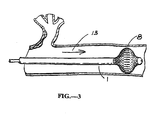
- FIG. 3 a preferred embodiment is illustrated in a schematic view.
- This is the expanded device 1 in place in a tubular channel of the body.
- This figure shows the instant invention as anchor and subsequent tensioner if so desired for the particular application.
- it could be the preferred embodiment of a flow directed guide wire or device if there is flow in the tubular channel as indicated by the arrow 13.
- the mechanisms of the preferred embodiment are shown here in FIGS. 3 & 4 inside a tubular channel.
- the preferred embodiment of the instant invention could be used for other anchoring as heretofore disclosed.
- This anchor could be used for closing percutaneous punctures in the femoral artery for example as well. This is a ubiquitous problem.
- the anchor By deploying the anchor on the inside of the puncture of the vessel (artery or vein), the puncture wound would seal faster. Further dehydrated collagen could be used to aid in this procedure. Even further, this anchor or occluder could be fabricated with bio-resorbable materials as required for the particular application.
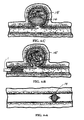
- FIG. 4-A a schematic illustration shows the occluder 14 in place in the vessel. This is accomplished by removing the support wire (inner wire or tube 3 and outer shell 2) as described heretofore.
- FIG. 4-B shows the instant invention 1 in its smaller condition as it is being passed into a vessel with an aneurysm 15.
- FIG. 4-C illustrates the occluder 14 in position in the aneurysm thus providing a novel therapy to this dangerous disease.
- the 'desired' location of the device is usually determined using Image Intensification (Fluoroscopy, Ultrasound Imaging, MRI, etc.). Further, the location could be monitored using cameras or other visualization techniques.
- Image Intensification Fluoroscopy, Ultrasound Imaging, MRI, etc.
- apparatus of the instant invention includes an elongate tube; an elongate mandril inside the tube and an expandable tubular braid.
- the elongate mandril extends from the proximal end of the device to the distal end.
- the elongate tube usually extends from close to the proximal end of the device to close to the distal end.
- the distal end of the tubular braid is bonded to the distal end of the inner elongate mandril.
- the mandril may extend beyond the tubular braid.
- the proximal end of the tubular braid is bonded to the distal end of the elongate tube.
- the braid may be open in embodiments not according to the invention, but may be laminated or covered with a coating of elastic, generally inelastic, plastic or plastically deformable material, such as silicone rubber, latex, polyethylene, thermoplastic elastomers (such as C-Flex, commercially available from Consolidated Polymer Technology), polyurethane and the like.
- elastic, generally inelastic, plastic or plastically deformable material such as silicone rubber, latex, polyethylene, thermoplastic elastomers (such as C-Flex, commercially available from Consolidated Polymer Technology), polyurethane and the like.
- the assembly of tube, mandril and braid is introduced percutaneously in its radially compressed state. In this state, the outside diameter of the braid is close to the outside diameter of the elongate tube. This diameter is in the range of 10 to 500 mils, and usually 25 to 250 mils (i.e. thousandth of an inch). After insertion, moving the mandril proximally with respect to the tube expand
- the tubular braid is preferably formed as a mesh of individual non-elastic filaments (called “yams” in the braiding industry). However, it can have some elastic filaments interwoven to create certain characteristics.
- the non-elastic yarns can be materials such as polyester, PET, polypropylene, polyamide fiber (Kevlar, DuPont), composite filament wound polymer, extruded polymer tubing (such as Nylon II or Ultem, commercially available from General Electric), stainless steel, Nickel Titanium (Nitinol), or the like so that axial shortening causes radial expansion of the braid. These materials have sufficient strength so that the expanding element will retain its expanded condition in the lumen of the body while removing the matter therefrom.
- all expandable mechanisms described heretofore can be manufactured using shape memory materials so that they are self expanding or even expandable when certain temperatures or thermal energies are delivered to the mechanisms.
- shape memory materials can be accomplished with different programming methods such as, but not limited to Two Way Shape Memory (TWSM) alloys.
- TWSM Two Way Shape Memory
- the braid may be of conventional construction, comprising round filaments, flat or ribbon filaments, square filaments, or the like.
- Non-round filaments may be advantageous to decrease the axial force required for expansion to create a preferred surface area configuration or to decrease the wall thickness of the tubular braid.
- the filament width or diameter will typically be from about 0.5 to 50 mils, usually being from about 5 to 20 mils.
- Suitable braids are commercially available from a variety of commercial suppliers.
- the tubular braids are typically formed by a "Maypole" dance of yam carriers.
- the braid consists of two systems of yarns alternately passing over and under each other causing a zigzag pattern on the surface.
- One system of yarns moves helically clockwise with respect to the fabric axis while the other moves helically counter-clockwise.
- the resulting fabric is a tubular braid.
- Common applications of tubular braids are lacings, electrical cable covers (i.e. insulation and shielding), "Chinese hand-cuffs" and reinforcements for composites.
- To form a balanced, torque-free fabric (tubular braid) the structure must contain the same number of yarns in each helical direction.
- the tubular braid may also be pressed flat to form a double thickness fabric strip.
- the braid weave used in the tubular braid of the present invention will preferably be of the construction known as "two dimensional, tubular, diamond braid” that has a 1/1 intersection pattern of the yarns which is referred to as the "intersection repeat".
- a Regular braid with a 2/2 intersection repeat and a Hercules braid with an intersection repeat of 3/3 may be used.
- the helix angle (that being the angle between the axis of the tubular braid and the yam) will increase as the braid is expanded.
- Longitudinal Lay-Ins can be added within the braid yarns and parallel to the axis to aid with stability, improve tensile and compressive properties and modulus of the fabric.
- the tubular braid is known as an elastic braid.
- the fabric is called a rigid braid.
- Biaxially braided fabrics such as those of the present invention are not dimensionally stable. This is why the braid can be placed into an expanded state from a relaxed state (in the case of putting it into the compressive mode). Alternatively this could be a decreased/reduced (braid diameter decreases) state when put into tension from the relaxed state. When put into tension (or compression for that matter) the braid eventually reaches a state wherein the diameter will decrease no more. This is called the "Jammed State”. On a stress strain curve, this corresponds to increase modulus.
- the guide wire, catheter, endoscope or other device of the present idea has an outer diameter that ranges from 0.15-8.00mm (.006" to .315"), but can extend to smaller and larger sizes as technology and procedures require.
- the device of the present idea will have a predetermined shaped (probably circular in diameter of 150-250mm (6-10")) coiled in the package, "as supplied".
- the product/device may be supplied straight but may have a shape at the distal end.
- the distal end may be tapered to a smaller distal diameter. This tapering may occur in the distal 150-300mm (6-12") of the device, but could occur over a greater length and there may be more than one taper along its length.
- the device may have a shaped tip or a tip that may be malleable so that the user prior to introduction may shape it.
- the device of the instant invention may have conventional lubricious coatings to enhance introduction into the target body lumen, e.g. hyaluronic or other equivalent coatings. Further, the user, prior to insertion may apply a lubricious coating. This may be extremely useful in the case of a reusable device (like an endoscope). As an advantage of the present idea, the device will be less difficult to feed it to the desired location in the body. Further difficulty will be greatly decreased for placement of other devices over or with the inner device. Even further, the instant invention will be less difficult to remain in the target location. This decreased difficulty will decrease cost due to time in the Operating Room (Operating Rooms costs are estimated in excess of $90 dollars per minute in the U.S.) or other environment. Additionally, the decrease in difficulty will aid in patient care and the potential in deleterious effects due to the inability to place the device in the appropriate position in the patient and keep it there or to place other devices with the present idea.
- a lubricious coating to enhance introduction into the target body lumen
- the user
- This mechanism may be at the tip or somewhere else in the distal portion of the device. Additionally, this mechanism may be any of a number of mechanisms that will help aid in moving the device using the physiological environment of the body. Alternatively, this distal mechanism may be used for anchoring, flow direction, tensioning or occluding. In this particular embodiment, a distal portion of the device may not coiled and will thus retain the malleable or resilient characteristics typical of conventional devices.
Landscapes
- Health & Medical Sciences (AREA)
- Surgery (AREA)
- Life Sciences & Earth Sciences (AREA)
- Molecular Biology (AREA)
- General Health & Medical Sciences (AREA)
- Vascular Medicine (AREA)
- Engineering & Computer Science (AREA)
- Biomedical Technology (AREA)
- Heart & Thoracic Surgery (AREA)
- Medical Informatics (AREA)
- Reproductive Health (AREA)
- Animal Behavior & Ethology (AREA)
- Nuclear Medicine, Radiotherapy & Molecular Imaging (AREA)
- Public Health (AREA)
- Veterinary Medicine (AREA)
- Neurosurgery (AREA)
- Media Introduction/Drainage Providing Device (AREA)
- Surgical Instruments (AREA)
- Steering Control In Accordance With Driving Conditions (AREA)
- Micromachines (AREA)
- Superconductors And Manufacturing Methods Therefor (AREA)
Abstract
Description
- The present invention relates to medical devices. In particular, the present idea relates to improved guide wires or catheters and method for their use, where the devices have a distal mechanism that acts as a mechanism for: I. Flow Directed, using the natural flowing fluids, pressure differentials or contractile forces of the body onto the distal mechanism to direct its motion and direction of 2. Anchored, so that once the device is in the desired location, it can be anchored against the tissue where it rests; 3. Tensioned, so that placement of a device, over the guide wire is accomplished with less difficulty and 4, Occluded, so that vessels and aneurysms can be occluded.
- Guide wire management in the operating room is problematic, and threading the needle of the arteries or other vessels including, but not limited to veins, intestines, fallopian tubes, etc, to reach the area to be treated is difficult. Further, once the guide is in the desired location, it is often difficult to make certain that the it remains in that location. Even further, once the guide wire, catheter, endoscope or other device is in the desired location and another device is placed over, through or along side it, the initially placed device has a tendency to move due to the forces exerted on it when other devices are using it as a guide.
- Additionally, other anchors are required for attaching tissue or other matter to improved or different locations within the body.
- Even further, vessel occluders are often required for a variety of medical procedures.
- For these reasons, it is desirable to provide an improved devices and methods for their use, which facilitate 1. using the physiologic motions of the body to help direct the device. In addition, flow pressure differential can be artificially created or enhanced by the technician/physician so that this same technology can be used when physiologic means is unavailable or insufficient. Further, the natural contractile forces of the body (e.g. those of the intestinal tract, gall bladder, esophagus, etc.) can be harnessed so that the device including, but not limited to guide wires, catheters, endoscopes, etc. are moved along with those forces. 2. Even further, it is desirable to provide a device that has an anchoring mechanism on it so that it will not move once in its desired position. 3. And yet even another desired characteristic would be to provide an anchored device that has a tensioning characteristic applied to it for placement of other devices over through or along side the first placed device. 4. And finally, another desired characteristic is that of a simple and effective occlusion system.
- There is a continuing need for improved devices to meet at least the following objectives.
- The first objective is to reduce cost. This is particularly important in recent years where it is clear for safety and sanitary reasons that these will be single use devices. A device, although it performs a function in some improved manner, will not be widely used if it is considerably more costly than the alternatives available.
- A second objective is to provide a device that is simple to use and in a very real sense simple to understand. This will encourage its adoption and use by medical personnel, It will also tend to keep cost low.
- The third objective is to provide a device that entails a procedure with which the medical profession is familiar so that the skills that have been learned from previous experience will continue to have applicability.
- A fourth objective relates to the effectiveness and thoroughness with which the device is intended,
- A fifth objective concerns safety; a matter which is often so critical as to trump the other considerations. It is important to avoid unnecessary tissue trauma.
- There are trade-offs in design considerations to achieve the above five interrelated objectives. Extreme simplicity and a very simple procedure might over compromise safety. Addressing all of these considerations calls for some trade-off between the objectives.
- Accordingly, a major object of this invention is to provide an improved occlusion, tensioning, anchoring and flow device that achieves the objectives of reduced cost, enhanced simplicity, a standard procedure, high effectiveness and a high degree of safety. Most particularly, it is an object of this invention to achieve these objectives with an enhanced trade-off value for the combined objectives.
- For these reasons, it is desirable to provide an improved device that may circumvent some of the problems associated with previous techniques. This improved medical device provides a new configuration that will eliminate some of those problems and methods for their use, which facilitate removal of vascular obstructions in the operating room or interventional suite.
- Pertinent descriptions are set forth in a number of issued U.S. patents, including
U.S. Patent nos. 5,275,611 ,5,312,360 ,4,696,304 ,5,176,659 ,5,437,631 ,5,606,979 ,5,779,672 ,5,456,667 ,5,733,294 and5,209,727 . A pin vise for helping grip the proximal end of a guide wire is illustrated inU.S. Patent No. 4,858,810 .U.S. Patent Nos. 5,275,611 ,5,312,360 describe a tension guide and dilator.U.S.Patent No. 5,779,672 describes a detachable inflatable occlusion balloon.U.S. Patent No. 5,456,667 describes a temporary stent on a catheter.U.S. Patent No. 5,733,294 describes a self-expanding cardiovascular occlusion device.U.S. Patent Nos. 5,437,631 ,5,591,204 and5,383,897 describe a puncture wound sealer.U.S. Patent No. 5,626,614 describes a tissue anchor for anchoring the stomach to the abdominal wall.U.S. Patent No. 4,372,293 describes an instrument for the surgical correction of ptotic breasts.U.S. Patent Nos. 5,730,733 and5,336,205 describe flow-assisted catheters. - There is known from
US 3,996,938 a blood vessel device comprising a support wire having a shell and core, supporting a braided element, the element being movable from a radially compressed state for insertion to a radially expanded state by exerting axial compression on it using the shell and core. - There is known from
DE-U-9205797 a blood vessel occluder comprising a braided expandable element whose openings may be filled by a film to render it non-porous. -
EP-A-0818180 discloses endoscopic medical devices in both braided and malecot forms. -
WO-A-96/01591 - According to the present invention, there is provided a device as set out in claim 1.
- An embodiment of the instant invention provides a device in which at least a distal portion of the shaft is configured so that it can assume a shape(s) along its shaft (proximally, mid-section or distally) that will act as an 'umbrella' type configuration. In the case of body channels or cavities, this expanded mochanism(s) is moved along the lumen (artery, vein) until it is in the desired location and is then deployed. For using the instant invention as a flow directed device, the expanding element is deployed when in position to be carried with the flow in the channel. Once the device is in the desired location, the user (physician/technician) can actuate the expanding mechanism(s) so that it is enlarged beyond its original size/diameter and aid in carrying the support wire, anchoring the wire, tensioning the wire or causing occlusion. MIS (Minimally Invasive Surgery) or LIS (Least invasive Surgery) devices described herein such as catheters and guide wires, for example are the most common tools used by least invasive interventionalists today. These devices are available in a variety of shapes and sizes from 0.2-12.7mm (.008-. 500") diameters and from 0.15-2.03m (6.0-80.0") in length. In other respects, the catheters and guide wires or other device(s) of the instant invention will have the geometries, characteristics, and dimensions of those commonly employed for the intended purpose (e.g. introduction to a blood vessel (LIS) or surgical tissue anchoring or occlusion (MIS). MIS and LIS are often interchanged in their usage. Usually LIS refers to catheters, guide wires, (and the like) that are used within the body, often within the channels of the body. MIS typically refers to videoscopic surgery where miniature cameras are used to accomplish surgery.
- However, because of the large crossover of the use of these terms, the inventors do not wish to limit the scope of the devices described herein when these terms are used.
- Further, embodiments of the instant invention provide for an anchor located along its shaft (usually at its distal portion). This anchor allows the device to maintain the desired position once it is in the desired location. This anchor allows a tension to be applied to the so that another structure can be more easily placed with the first device. Alternatively this tension may not be required, but just the anchor so that an another member can be advanced with the help of the first member and without loosing the preferred location.
- Guide wires are the most common tools used by least invasive interventionalists today. These guide wires are available in a variety of shapes and sizes from 0.2-1.14mm (.008-. 045") diameters and from 0.15-2.03m (6.0-80.0") in length. The guide wires may will have the geometries, characteristics, and dimensions of those commonly employed for the intended purpose, e.g. introduction to a blood vessel. Typically, for vascular applications, the flexible core will have a length in the range from 10 cm to 300 cm diameter and in the range from 0.1 mm to 1mm.
- Additionally there are a variety of configurations such as floppy, J-Tip, stiff, Moveable Core, Nitinol, Stainless Steel, Polymer Coated, Lubricious Coated, just to name a few. The instant invention can be used with any of the existing guide wires that are commercially available today and that may become commercially available in the future. As stated above the characteristic design of the instant invention is that at least a portion of the distal end of the wire (or other device) has some mechanism that allows physiological forces (or other artificially created forces) in the lumens of the body to carry the guide wire to a desired location or that the distal shape mechanism allows for anchoring or that the distal shape allows for tension to be applied to the wire, catheter or other device or that the distal expanded braided element is used as an occluder.
- One embodiment of this invention is particularly adapted to the anchoring of wires or tubes within the tubular channels of the body including veins and arteries.
- In an embodiment the support wire is a dual element support wire having a core and an annular shell that slides on the core. The distal end of the core is attached to the distil end of the annular braided element and the distal end of the shell is attached to the proximal end of the annular braided element. Thus movement of the core and shell relative to one another moves the braided element from a radially retracted position which is useful for insertion into the body to a radially expanded position which expands it to the sidewall of the tubular channel or against other tissue or matter within the body. When the annular braided element is in its radially compressed (smaller diameter) state, it can be passed through or around occlusions together with the rest of the wire to reside on the distal end of the occlusion in the case of tubular channels with occlusions. It is a preferred embodiment of the instant invention that it can be made very small. When the braided element is expanded and pulled proximally (that is, in a retrograde fashion), it will engage the walls of the tubular channel and the elongate support wire can be put into tension. This distal engaging tubular braid element is covered by or integrated with a thin film or membrane to create patency or other desirable characteristics.
- In another embodiment the tubular braid distal expansile mechanism may be used on the end of a guide wire or catheter so that once deployed in a tubular channel with flow such as arteries and veins, the expanded mechanism can carry the support wire in the direction of the flow. In order to accomplish this flow characteristic it may be desirable to deploy the distal expanding tubular braid whereby the support wire becomes 'floppy' in nature so that it will flow with the expanded 'umbrella'. The author uses the phrase 'umbrella' only as a communication tool in that an umbrella starts out with a small diameter shaft in its un-deployed condition (radially compressed condition) and ends up with a large diameter configuration when deployed. The shape of the expanding mechanism is varied and includes, but is not limited to an umbrella shape, a spheroid shape, an ovoid shape, a conical shape, a disc-shape, etc. The inventors have fabricated at least all of the aforementioned shapes using tubular/annular braid and successfully tested the flow, anchoring, tensioning and occlusion characteristics in both a static and dynamic in vitro environment. Creating the expanded annular braided mechanism is accomplished by pulling the inner wire of the support wire out of the outer tube. The outer tube can be made of very flexible material so that the inner wire gives the structure all of the support. When the 'umbrella reaches the desired location which is usually determined by image intensification including, but not limited to x-ray, ultrasound, MRI, etc., the inner wire can be ra-insated into the flexible outer tube of the support wire to give the desired support required. Also once the 'umbrella' with the flexible outer tube needs to be removed, the inner wire can be an actuator to un-deploy the expanded braided element back to its smaller and radially compressed size. This is accomplished by bonding the outer tube of the support wire to the distal end of the tubular braid expanding element and the inner wire of the support wire is slightly bonded to the distal end of the braided expanding element. This slight bond could also be an interference fit where the inner wire snaps into and out of the distal end of the braided expanding element.
- Even further, by making another minor change the braided expanding element may be used as a permanent or temporary occluder without the support wire being left in place. This is accomplished by having the outer tube not bonded to the proximal end of the expanding element and the inner wire of the support wire to be only slightly bonded to the distal end of the expanding braided element. In this case, the inner wire is pulled in a retrograde direction relative to the outer tube. This action causes the expanding braided element to expand radially. Once the expanding element expands to the desired shape for the particular application and occlusion, the inner wire is pulled out of the 'snap' or interference fit on the distal end of the expanding braided element and the expanded braid occluder is left in place when both the inner and outer member of the support wire is removed from the body.
- Hence, nearly the same invention allows the use for four different applications in the health care field.
-
-
FIG. 1 is a schematic illustration of a guide wire or catheter constructed in accordance with the principles of the present idea.FIG. 1-A is an illustration of the expandable guide wire or catheter in its relaxed un-deployed state (normally closed).FIG. 1-B is a schematic illustration of the expandable guide wire or catheter in its expanded state.FIG. 1-C is a schematic illustration of the 'detached' occluder. -
FIG. 2 is a schematic illustration of the annular or tubular braid used in the instant invention. -
FIG. 3 is a schematic illustration of the expanded braided 'umbrella' mechanism in place in a tubular channel of the body where the expanding element is used as an occluder, anchor, flow director or tensioner. -
FIG. 4 illustrates the instant invention as it is being used as a detachable occluder.FIG. 4-A is a schematic illustration of the detached occluder in place in a tubular channel within the body.FIG. 4-B is a schematic illustration of the occluder being advanced in a tubular channel toward an aneurysm.FIG. 4-C is a schematic illustration of the detached occluder in place in the aneurysm. - Although the instant invention in
FIG1-B illustrates a relative motion of the inner and outer elongate member, it is recognized and disclosed heretofore that the expanding mechanism may be deployed any number of ways falling within the scope of the claims including, but not limited to self expansion (permanent set in the expanding mechanism that is constrained by an outer tubular channel prior to deployment, magnetic means, thermal gradient mechanisms, electrical stimulation, etc. - Although the instant invention relates to four basic embodiments, those being flow directed, anchoring, tensioning and occluding, the instant invention is submitted for prosecution because the four embodiments are so closely related Further and equally important is that the mechanical configuration(s) for all four embodiments of the present invention are similar.
- The device of the instant invention is used for intervention into the tubular channels (lumens) of the body including, arteries, and veins. Even further, the instant invention is used for the repair of aneurysms of other permanent vessel occlusions. Such other permanent vessel occlusions would have applicability for occlusion of tributaries of vessels for vessel harvesting. The instant invention is particularly convenient to use in an operating room, interventional suite, patients' bedside, in an emergency room environment or in any emergency situation. One preferred embodiment of the instant invention is that it is inserted into the tubular channel of the body to utilize the flow directed characteristics of the invention. Once the device is in a flow/differential pressure situation, the inner core, mandrel/wire/string/member is deployed (usually pulled by the physician outside the body) so that the umbrella/trap configuration on the distal portion of the device opens. At the same time, the distal portion of the device becomes 'floppy' in nature so that it will follow the tortuous paths of the lumen without causing deleterious complications normally realized with conventional guide wires where they inadvertently damage the inner wall of the vessel when trying to cross said tortuous paths. The device is then carried in the direction of flow or of lower pressure (or with any contractile forces that may exist).
- Once the device is in the desired position within the body, the umbrella like mechanism may or may not be un-deployed. In this case, once the device is removed from the package and before insertion into the body, the mechanism on the distal portion of the guide wire may be unopened (normally closed).
- Alternatively, the device could have a distal configuration that causes it be moved in the direction of flow or in the direction of less pressure (or with the contractile forces) at the time it is opened from the package (e.g. normally opened). In this case the device is placed in the motion situation in the tubular channel of the body and is carried to the desired location. In the normally open position, the device may be very floppy in nature so that it will easily travel through the lumen of the body due to the pressure differential/flow/contractile forces. Once in position, the mechanism at the distal portion of the device may or may not be closed by some other mechanical means by the technician outside the body. One way of undeploying the distal 'umbrella' mechanism is by re-inserting the inner core so that the expanded mechanism becomes small or in its radially compressed state. Another advantage of re-inserting the inner core wire into the outer 'floppy' tube would be to make the support wire somewhat stiff, facilitating the insertion of another device over, through or along side the support wire that is attached to the expandable mechanism. Further, the umbrella like mechanism could become enlarged so that it will anchor in the lumen to keep its desired position.
- Possible configurations of the distal mechanism are varied. One such mechanism in embodiments not according to the invention is a balloon that is inflated for flow and deflated when not required. Another configuration that could be used is a mechanism known as a malecot. This malecot is a common configuration used in catheters for holding them in place (in the case of feeding tubes in the intestines). It is usually a polymeric tube that has four slits diametrically opposed. When the distal tip of the malecot is put into compression (usually by pulling an inner wire or member), the four sides of the polymer are pushed outward so as to create a larger diameter on the distal tip. Alternatively, the normal configuration of the malecot could be an open configuration whereby, when put into tension (large or small), the malecot closes to come near to or equal to the diameter of the elongated member. This larger diameter is larger than the body length of the catheter or wire. Another alternative is one that is similar to the malecot, but uses a multi-stranded braid on the distal end. When the braid is put into compression, the braid is pulled together and it flares out to create a larger diameter only the distal end. Alternatively either the braid or the malecot can have a permanent set put into in so that it is normally open or of the larger diameter. In this case, when it is put into tension (usually from some inner core wire or mandrel) it collapses down to the diameter of the body of the wire or catheter. Even further, the expandable mechanism on the distal end of these devices could be programmed to be thermally sensitive so that they expand or contract when placed in desired thermal gradients. One such mechanism for 'programming' materials like this is known as Shaped Memory Alloys (SMA) or Two Way Shaped Memory Alloys (TWSMA).
Another exemplary embodiment of the instant invention is that once the device is placed in its desired location the mechanism (usually near the distal portion of the device) is deployed to 'lock' or 'anchor' it in the desired position. - Another embodiment is the tensioning characteristic of the instant invention. When the device is in or near a desired location of the body, the distal mechanism is deployed so that it anchors or has a tendency not to move. In this configuration, the wire, catheter or other device can be put into tension that will allow the passage of another device over or with the inner support wire. Even further and discussed heretofore, the instant invention can be 'detached' from the support wire and act as a tubular channel occluder.
- This anchoring mechanism may or may not be used with the other embodiments. Further, the flow/contractile force characteristic may or may not be used with the other embodiments. Even further, the tensioning characteristic may or may not be used with the other embodiments. Last, the occluder may be used independently of the other three. In other words, although the distal mechanism that is used for all four embodiments may be similar to one another, the separate four embodiments may be used alone or in combination with the other embodiments.
- Referring now to the figures, the four embodiments of the instant invention are illustrated.
- Turning now to
FIG. 1-A , a preferred embodiment of the instant invention is illustrated using a schematic drawing. The radially compressed, smaller support wire 1 is illustrated. Theshaft 2 is a tubular outer shell where the inner wire ortube 3 rests. Theinner tube 3 is attached to the distal end of the annular braid 4 at 5. Theouter shell 2 may be attached to the annular braid at 6. In the case of the detachable occluder inFIG. 1-C , it may not be attached so that the occluder is set free in the desired location. - Referring now to
FIG 1-B , the inner tube orwire 3 is moved relative to theouter shell 2 as indicated by the arrow 7. This relative motion causes the annular braid 4 to expand radially as shown at 8. The shapes shown in these figures show an ovoid shape, however the shape can vary significantly as described heretofore. Notice that there is a through lumen illustrated inside theinner tube 3 and is further indicated at the distal tip of the assembly by 9. This may or may not be required depending on the application. - Turning now to
FIG. 1-C , the preferred embodiment of the instant invention as an occluder 10 is illustrated in the schematic. - Referring now to
FIG. 2-A and 2-B , a schematic view of the annular or tubular braid is illustrated.FIG. 2-A illustrates the annular braid in its relaxed, smaller or compressed state 11.FIG. 2-B illustrates the annular braid in its expandedstate 12. The expansion is achieved by putting the braid into a compressive mode and changing the overall length of the braid. This can also be accomplished with self expanding of the braid by programming it with thermal treatments or using SMA (Shaped Memory Alloys) or by using a thermal change to change the shape of the device with a technique known as TWSMA (Two Way Shape Memory Alloy). - Turning now to
FIG. 3 , a preferred embodiment is illustrated in a schematic view. This is the expanded device 1 in place in a tubular channel of the body. This figure shows the instant invention as anchor and subsequent tensioner if so desired for the particular application. Further, it could be the preferred embodiment of a flow directed guide wire or device if there is flow in the tubular channel as indicated by thearrow 13. The mechanisms of the preferred embodiment are shown here inFIGS. 3 &4 inside a tubular channel. However, the preferred embodiment of the instant invention could be used for other anchoring as heretofore disclosed. This anchor could be used for closing percutaneous punctures in the femoral artery for example as well. This is a ubiquitous problem. By deploying the anchor on the inside of the puncture of the vessel (artery or vein), the puncture wound would seal faster. Further dehydrated collagen could be used to aid in this procedure. Even further, this anchor or occluder could be fabricated with bio-resorbable materials as required for the particular application. - Turning now to
FIG. 4-A , a schematic illustration shows theoccluder 14 in place in the vessel. This is accomplished by removing the support wire (inner wire ortube 3 and outer shell 2) as described heretofore.FIG. 4-B shows the instant invention 1 in its smaller condition as it is being passed into a vessel with ananeurysm 15.FIG. 4-C illustrates theoccluder 14 in position in the aneurysm thus providing a novel therapy to this dangerous disease. - In any of these instances, the 'desired' location of the device is usually determined using Image Intensification (Fluoroscopy, Ultrasound Imaging, MRI, etc.). Further, the location could be monitored using cameras or other visualization techniques.
- In one embodiment apparatus of the instant invention includes an elongate tube; an elongate mandril inside the tube and an expandable tubular braid. The elongate mandril extends from the proximal end of the device to the distal end. The elongate tube usually extends from close to the proximal end of the device to close to the distal end. The distal end of the tubular braid is bonded to the distal end of the inner elongate mandril. The mandril may extend beyond the tubular braid. The proximal end of the tubular braid is bonded to the distal end of the elongate tube.
- The braid may be open in embodiments not according to the invention, but may be laminated or covered with a coating of elastic, generally inelastic, plastic or plastically deformable material, such as silicone rubber, latex, polyethylene, thermoplastic elastomers (such as C-Flex, commercially available from Consolidated Polymer Technology), polyurethane and the like. The assembly of tube, mandril and braid is introduced percutaneously in its radially compressed state. In this state, the outside diameter of the braid is close to the outside diameter of the elongate tube. This diameter is in the range of 10 to 500 mils, and usually 25 to 250 mils (i.e. thousandth of an inch). After insertion, moving the mandril proximally with respect to the tube expands the tubular braid.
- The tubular braid is preferably formed as a mesh of individual non-elastic filaments (called "yams" in the braiding industry). However, it can have some elastic filaments interwoven to create certain characteristics. The non-elastic yarns can be materials such as polyester, PET, polypropylene, polyamide fiber (Kevlar, DuPont), composite filament wound polymer, extruded polymer tubing (such as Nylon II or Ultem, commercially available from General Electric), stainless steel, Nickel Titanium (Nitinol), or the like so that axial shortening causes radial expansion of the braid. These materials have sufficient strength so that the expanding element will retain its expanded condition in the lumen of the body while removing the matter therefrom. Further, all expandable mechanisms described heretofore, can be manufactured using shape memory materials so that they are self expanding or even expandable when certain temperatures or thermal energies are delivered to the mechanisms. Such material characteristics can be accomplished with different programming methods such as, but not limited to Two Way Shape Memory (TWSM) alloys.
- The braid may be of conventional construction, comprising round filaments, flat or ribbon filaments, square filaments, or the like. Non-round filaments may be advantageous to decrease the axial force required for expansion to create a preferred surface area configuration or to decrease the wall thickness of the tubular braid. The filament width or diameter will typically be from about 0.5 to 50 mils, usually being from about 5 to 20 mils. Suitable braids are commercially available from a variety of commercial suppliers.
- The tubular braids are typically formed by a "Maypole" dance of yam carriers. The braid consists of two systems of yarns alternately passing over and under each other causing a zigzag pattern on the surface. One system of yarns moves helically clockwise with respect to the fabric axis while the other moves helically counter-clockwise. The resulting fabric is a tubular braid. Common applications of tubular braids are lacings, electrical cable covers (i.e. insulation and shielding), "Chinese hand-cuffs" and reinforcements for composites. To form a balanced, torque-free fabric (tubular braid), the structure must contain the same number of yarns in each helical direction. The tubular braid may also be pressed flat to form a double thickness fabric strip. The braid weave used in the tubular braid of the present invention will preferably be of the construction known as "two dimensional, tubular, diamond braid" that has a 1/1 intersection pattern of the yarns which is referred to as the "intersection repeat". Alternatively, a Regular braid with a 2/2 intersection repeat and a Hercules braid with an intersection repeat of 3/3 may be used. In all instances, the helix angle (that being the angle between the axis of the tubular braid and the yam) will increase as the braid is expanded. Even further, Longitudinal Lay-Ins can be added within the braid yarns and parallel to the axis to aid with stability, improve tensile and compressive properties and modulus of the fabric. When these longitudinal "Lay-In" yarns are elastic in nature, the tubular braid is known as an elastic braid. When the longitudinal yarns are stiff, the fabric is called a rigid braid. Biaxially braided fabrics such as those of the present invention are not dimensionally stable. This is why the braid can be placed into an expanded state from a relaxed state (in the case of putting it into the compressive mode). Alternatively this could be a decreased/reduced (braid diameter decreases) state when put into tension from the relaxed state. When put into tension (or compression for that matter) the braid eventually reaches a state wherein the diameter will decrease no more. This is called the "Jammed State". On a stress strain curve, this corresponds to increase modulus. Much of the engineering analyses concerning braids are calculated using the "Jammed State" of the structure/braid. These calculations help one skilled in the art to design a braid with particular desired characteristics. Further, material characteristics are tensile strength, stiffness and Young's modulus. In most instances, varying the material characteristics will vary the force with which the expanded condition of the tubular can exert radially. Even further, the friction between the individual yarns has an effect on the force required to compress and un-compress the tubular braid. For the present invention, friction should be relatively low for a chosen yam so that the user will have little trouble deploying the engaging element. This is particularly important when the engaging element is located a significant distance from the user. Such is the case when the percutaneous entry is the groin (Femoral Artery for vascular interventions) and the point of engaging the engaging element is some distance away (i.e. the Carotid Artery in the neck). Similarly, this is true for long distances that are not vascular or percutaneous applications.
- An exemplary device has the following characteristics:
- 30-500 cm
- The guide wire, catheter, endoscope or other device of the present idea has an outer diameter that ranges from 0.15-8.00mm (.006" to .315"), but can extend to smaller and larger sizes as technology and procedures require.
- The device of the present idea will have a predetermined shaped (probably circular in diameter of 150-250mm (6-10")) coiled in the package, "as supplied". Alternatively the product/device may be supplied straight but may have a shape at the distal end. The distal end may be tapered to a smaller distal diameter. This tapering may occur in the distal 150-300mm (6-12") of the device, but could occur over a greater length and there may be more than one taper along its length. Optionally, the device may have a shaped tip or a tip that may be malleable so that the user prior to introduction may shape it.
- The device of the instant invention may have conventional lubricious coatings to enhance introduction into the target body lumen, e.g. hyaluronic or other equivalent coatings. Further, the user, prior to insertion may apply a lubricious coating. This may be extremely useful in the case of a reusable device (like an endoscope). As an advantage of the present idea, the device will be less difficult to feed it to the desired location in the body. Further difficulty will be greatly decreased for placement of other devices over or with the inner device. Even further, the instant invention will be less difficult to remain in the target location. This decreased difficulty will decrease cost due to time in the Operating Room (Operating Rooms costs are estimated in excess of $90 dollars per minute in the U.S.) or other environment. Additionally, the decrease in difficulty will aid in patient care and the potential in deleterious effects due to the inability to place the device in the appropriate position in the patient and keep it there or to place other devices with the present idea.
- An exemplary device having an expanding 'umbrella' mechanism located on its distal tip is illustrated in the figures. This mechanism may be at the tip or somewhere else in the distal portion of the device. Additionally, this mechanism may be any of a number of mechanisms that will help aid in moving the device using the physiological environment of the body. Alternatively, this distal mechanism may be used for anchoring, flow direction, tensioning or occluding. In this particular embodiment, a distal portion of the device may not coiled and will thus retain the malleable or resilient characteristics typical of conventional devices.
- Although the foregoing idea has been described in some detail by way of illustration and example, for purposes of clarity of understanding, it will be obvious that certain changes and modifications may be practiced within the scope of the appended claims.
Claims (11)
- A medical device for use in a blood vessel of the body, comprising:a support wire insertable into the body, said wire comprising a shell (2) and an elongate core (3), said wire having a distal end;an expandable element (8) supported on said distal end of said wire, said expandable element movable from a radially compressed state, for insertion of said expandable element into the body, to a radially expanded state using the shell (2) and the elongate core (3) to axially compress and thereby radially expand said expandable element, said expandable element having openings which are at least substantially filled by a film to create a substantially non-porous expandable element wherein said expandable element comprises:an annular braided expandable element having said openings; ora multi-wing malecot expandable element having said openings.
- The device of claim 1 wherein:the film comprises a film layer;the annular braided expandable element comprises the expandable element and the film layer contacts the annular braided expandable element.
- The device of claim 1 wherein the expandable element is a releasable expandable element which is releasable from both the elongate core and the shell.
- The device of claim 3, wherein the expandable element is a flow-directed element.
- The device of claim 1 wherein said expandable element is one of:an anchoring element for a supplemental medical device;a tubular channel occlusion element; ora flow-directed, releasable expandable element.
- The device of claim 1 wherein said expandable element is sized so to contact a wall of a passageway in which it is inserted.
- The device of claim 1 wherein the expandable element is bio-resorbable.
- The device of claim 1 further comprising a locking mechanism maintaining the expandable element in the radially expanded state.
- The device of claim 1 wherein said expandable element is said annular braided expandable element and has individual yarns sufficiently flexible to be movable between said states and sufficiently stiff to substantially hold said expanded state when in a targeted area within a body.
- The device according to claim 1 further comprising securing means arranged to be located at a position external of the body, whereby the expandable element can be locked into a chosen radially expanded state within the body by the securing means.
- An occlusion element comprising a device in accordance with any one of the preceding claims.
Applications Claiming Priority (7)
| Application Number | Priority Date | Filing Date | Title |
|---|---|---|---|
| US7418398P | 1998-02-10 | 1998-02-10 | |
| US74183P | 1998-02-10 | ||
| US7728198P | 1998-03-09 | 1998-03-09 | |
| US77281P | 1998-03-09 | ||
| US10492298P | 1998-12-20 | 1998-12-20 | |
| US104922P | 1998-12-20 | ||
| PCT/US1999/002856 WO1999039649A1 (en) | 1998-02-10 | 1999-02-09 | Occlusion, anchoring, tensioning and flow direction apparatus and methods for use |
Publications (3)
| Publication Number | Publication Date |
|---|---|
| EP1054635A1 EP1054635A1 (en) | 2000-11-29 |
| EP1054635A4 EP1054635A4 (en) | 2007-05-02 |
| EP1054635B1 true EP1054635B1 (en) | 2010-01-06 |
Family
ID=27372424
Family Applications (1)
| Application Number | Title | Priority Date | Filing Date |
|---|---|---|---|
| EP99906869A Expired - Lifetime EP1054635B1 (en) | 1998-02-10 | 1999-02-09 | Occlusion, anchoring, tensioning or flow direction apparatus |
Country Status (7)
| Country | Link |
|---|---|
| US (2) | US6635068B1 (en) |
| EP (1) | EP1054635B1 (en) |
| JP (1) | JP2003522550A (en) |
| AT (1) | ATE454098T1 (en) |
| DE (1) | DE69941894D1 (en) |
| ES (1) | ES2343228T3 (en) |
| WO (1) | WO1999039649A1 (en) |
Cited By (27)
| Publication number | Priority date | Publication date | Assignee | Title |
|---|---|---|---|---|
| US9656047B1 (en) | 2014-12-05 | 2017-05-23 | Anchor Endovascular, Inc. | Anchor device for use with catheters |
| US10130372B2 (en) | 2014-04-30 | 2018-11-20 | Cerus Endovascular Limited | Occlusion Device |
| US10271863B2 (en) | 2014-03-04 | 2019-04-30 | Thrombx Medical, Inc. | Intravascular thromboembolectomy device comprising a plurality of clot engaging elements and method using the same |
| US10881419B2 (en) | 2011-07-26 | 2021-01-05 | Thrombx Medical, Inc. | Intravascular thromboembolectomy method |
| US10905430B2 (en) | 2018-01-24 | 2021-02-02 | DePuy Synthes Products, Inc. | Aneurysm device and delivery system |
| US10939915B2 (en) | 2018-05-31 | 2021-03-09 | DePuy Synthes Products, Inc. | Aneurysm device and delivery system |
| US11058430B2 (en) | 2018-05-25 | 2021-07-13 | DePuy Synthes Products, Inc. | Aneurysm device and delivery system |
| US11076860B2 (en) | 2014-03-31 | 2021-08-03 | DePuy Synthes Products, Inc. | Aneurysm occlusion device |
| US11076861B2 (en) | 2018-10-12 | 2021-08-03 | DePuy Synthes Products, Inc. | Folded aneurysm treatment device and delivery method |
| US11123077B2 (en) | 2018-09-25 | 2021-09-21 | DePuy Synthes Products, Inc. | Intrasaccular device positioning and deployment system |
| US11134953B2 (en) | 2019-02-06 | 2021-10-05 | DePuy Synthes Products, Inc. | Adhesive cover occluding device for aneurysm treatment |
| US11154302B2 (en) | 2014-03-31 | 2021-10-26 | DePuy Synthes Products, Inc. | Aneurysm occlusion device |
| US11272939B2 (en) | 2018-12-18 | 2022-03-15 | DePuy Synthes Products, Inc. | Intrasaccular flow diverter for treating cerebral aneurysms |
| US11278292B2 (en) | 2019-05-21 | 2022-03-22 | DePuy Synthes Products, Inc. | Inverting braided aneurysm treatment system and method |
| US11337706B2 (en) | 2019-03-27 | 2022-05-24 | DePuy Synthes Products, Inc. | Aneurysm treatment device |
| US11406392B2 (en) | 2018-12-12 | 2022-08-09 | DePuy Synthes Products, Inc. | Aneurysm occluding device for use with coagulating agents |
| US11413046B2 (en) | 2019-05-21 | 2022-08-16 | DePuy Synthes Products, Inc. | Layered braided aneurysm treatment device |
| US11457926B2 (en) | 2019-12-18 | 2022-10-04 | DePuy Synthes Products, Inc. | Implant having an intrasaccular section and intravascular section |
| US11497504B2 (en) | 2019-05-21 | 2022-11-15 | DePuy Synthes Products, Inc. | Aneurysm treatment with pushable implanted braid |
| US11504150B2 (en) | 2017-09-11 | 2022-11-22 | Thrombx Medical, Inc. | Intravascular thromboembolectomy devices and methods |
| US11583288B2 (en) | 2018-08-08 | 2023-02-21 | DePuy Synthes Products, Inc. | Delivery of embolic braid |
| US11583282B2 (en) | 2019-05-21 | 2023-02-21 | DePuy Synthes Products, Inc. | Layered braided aneurysm treatment device |
| US11596412B2 (en) | 2018-05-25 | 2023-03-07 | DePuy Synthes Products, Inc. | Aneurysm device and delivery system |
| US11602350B2 (en) | 2019-12-05 | 2023-03-14 | DePuy Synthes Products, Inc. | Intrasaccular inverting braid with highly flexible fill material |
| US11607226B2 (en) | 2019-05-21 | 2023-03-21 | DePuy Synthes Products, Inc. | Layered braided aneurysm treatment device with corrugations |
| US11672543B2 (en) | 2017-02-23 | 2023-06-13 | DePuy Synthes Products, Inc. | Aneurysm method and system |
| US11672542B2 (en) | 2019-05-21 | 2023-06-13 | DePuy Synthes Products, Inc. | Aneurysm treatment with pushable ball segment |
Families Citing this family (450)
| Publication number | Priority date | Publication date | Assignee | Title |
|---|---|---|---|---|
| US6176240B1 (en) | 1995-06-07 | 2001-01-23 | Conceptus, Inc. | Contraceptive transcervical fallopian tube occlusion devices and their delivery |
| US6705323B1 (en) | 1995-06-07 | 2004-03-16 | Conceptus, Inc. | Contraceptive transcervical fallopian tube occlusion devices and methods |
| US6006134A (en) | 1998-04-30 | 1999-12-21 | Medtronic, Inc. | Method and device for electronically controlling the beating of a heart using venous electrical stimulation of nerve fibers |
| US7569066B2 (en) | 1997-07-10 | 2009-08-04 | Boston Scientific Scimed, Inc. | Methods and devices for the treatment of aneurysms |
| US6146373A (en) | 1997-10-17 | 2000-11-14 | Micro Therapeutics, Inc. | Catheter system and method for injection of a liquid embolic composition and a solidification agent |
| US6511468B1 (en) * | 1997-10-17 | 2003-01-28 | Micro Therapeutics, Inc. | Device and method for controlling injection of liquid embolic composition |
| US9498604B2 (en) | 1997-11-12 | 2016-11-22 | Genesis Technologies Llc | Medical device and method |
| US20040260333A1 (en) * | 1997-11-12 | 2004-12-23 | Dubrul William R. | Medical device and method |
| US20040199202A1 (en) * | 1997-11-12 | 2004-10-07 | Genesis Technologies Llc | Biological passageway occlusion removal |
| US6635068B1 (en) * | 1998-02-10 | 2003-10-21 | Artemis Medical, Inc. | Occlusion, anchoring, tensioning and flow direction apparatus and methods for use |
| US20100030256A1 (en) | 1997-11-12 | 2010-02-04 | Genesis Technologies Llc | Medical Devices and Methods |
| US6450989B2 (en) * | 1998-04-27 | 2002-09-17 | Artemis Medical, Inc. | Dilating and support apparatus with disease inhibitors and methods for use |
| WO1999055285A2 (en) * | 1998-04-27 | 1999-11-04 | Dubrul William R | Dilating and support apparatus with disease inhibitors and methods for use |
| US20100036481A1 (en) * | 1998-04-27 | 2010-02-11 | Artemis Medical, Inc. | Cardiovascular Devices and Methods |
| US7335220B2 (en) | 2004-11-05 | 2008-02-26 | Access Closure, Inc. | Apparatus and methods for sealing a vascular puncture |
| US20020169473A1 (en) * | 1999-06-02 | 2002-11-14 | Concentric Medical, Inc. | Devices and methods for treating vascular malformations |
| US8414543B2 (en) | 1999-10-22 | 2013-04-09 | Rex Medical, L.P. | Rotational thrombectomy wire with blocking device |
| US8579966B2 (en) | 1999-11-17 | 2013-11-12 | Medtronic Corevalve Llc | Prosthetic valve for transluminal delivery |
| US8016877B2 (en) | 1999-11-17 | 2011-09-13 | Medtronic Corevalve Llc | Prosthetic valve for transluminal delivery |
| US7018406B2 (en) | 1999-11-17 | 2006-03-28 | Corevalve Sa | Prosthetic valve for transluminal delivery |
| US6660021B1 (en) | 1999-12-23 | 2003-12-09 | Advanced Cardiovascular Systems, Inc. | Intravascular device and system |
| US6575997B1 (en) | 1999-12-23 | 2003-06-10 | Endovascular Technologies, Inc. | Embolic basket |
| US6402771B1 (en) | 1999-12-23 | 2002-06-11 | Guidant Endovascular Solutions | Snare |
| US6695813B1 (en) | 1999-12-30 | 2004-02-24 | Advanced Cardiovascular Systems, Inc. | Embolic protection devices |
| US7918820B2 (en) | 1999-12-30 | 2011-04-05 | Advanced Cardiovascular Systems, Inc. | Device for, and method of, blocking emboli in vessels such as blood arteries |
| US8241274B2 (en) | 2000-01-19 | 2012-08-14 | Medtronic, Inc. | Method for guiding a medical device |
| US7749245B2 (en) | 2000-01-27 | 2010-07-06 | Medtronic, Inc. | Cardiac valve procedure methods and devices |
| US9522217B2 (en) | 2000-03-15 | 2016-12-20 | Orbusneich Medical, Inc. | Medical device with coating for capturing genetically-altered cells and methods for using same |
| US8460367B2 (en) | 2000-03-15 | 2013-06-11 | Orbusneich Medical, Inc. | Progenitor endothelial cell capturing with a drug eluting implantable medical device |
| US8088060B2 (en) | 2000-03-15 | 2012-01-03 | Orbusneich Medical, Inc. | Progenitor endothelial cell capturing with a drug eluting implantable medical device |
| US6632241B1 (en) * | 2000-03-22 | 2003-10-14 | Endovascular Technologies, Inc. | Self-expanding, pseudo-braided intravascular device |
| AU2001273088A1 (en) | 2000-06-30 | 2002-01-30 | Viacor Incorporated | Intravascular filter with debris entrapment mechanism |
| US6964670B1 (en) | 2000-07-13 | 2005-11-15 | Advanced Cardiovascular Systems, Inc. | Embolic protection guide wire |
| AU2001285078A1 (en) | 2000-08-18 | 2002-03-04 | Atritech, Inc. | Expandable implant devices for filtering blood flow from atrial appendages |
| US7029486B2 (en) * | 2000-09-26 | 2006-04-18 | Microvention, Inc. | Microcoil vaso-occlusive device with multi-axis secondary configuration |
| US20060135947A1 (en) * | 2000-10-27 | 2006-06-22 | Pulmonx | Occlusal stent and methods for its use |
| US6506203B1 (en) | 2000-12-19 | 2003-01-14 | Advanced Cardiovascular Systems, Inc. | Low profile sheathless embolic protection system |
| US7338510B2 (en) | 2001-06-29 | 2008-03-04 | Advanced Cardiovascular Systems, Inc. | Variable thickness embolic filtering devices and method of manufacturing the same |
| US8771302B2 (en) | 2001-06-29 | 2014-07-08 | Medtronic, Inc. | Method and apparatus for resecting and replacing an aortic valve |
| US7544206B2 (en) | 2001-06-29 | 2009-06-09 | Medtronic, Inc. | Method and apparatus for resecting and replacing an aortic valve |
| US6599307B1 (en) | 2001-06-29 | 2003-07-29 | Advanced Cardiovascular Systems, Inc. | Filter device for embolic protection systems |
| US8623077B2 (en) | 2001-06-29 | 2014-01-07 | Medtronic, Inc. | Apparatus for replacing a cardiac valve |
| FR2826863B1 (en) | 2001-07-04 | 2003-09-26 | Jacques Seguin | ASSEMBLY FOR PLACING A PROSTHETIC VALVE IN A BODY CONDUIT |
| FR2828091B1 (en) | 2001-07-31 | 2003-11-21 | Seguin Jacques | ASSEMBLY ALLOWING THE PLACEMENT OF A PROTHETIC VALVE IN A BODY DUCT |
| US20030028209A1 (en) * | 2001-07-31 | 2003-02-06 | Clifford Teoh | Expandable body cavity liner device |
| US6638294B1 (en) | 2001-08-30 | 2003-10-28 | Advanced Cardiovascular Systems, Inc. | Self furling umbrella frame for carotid filter |
| US6592606B2 (en) | 2001-08-31 | 2003-07-15 | Advanced Cardiovascular Systems, Inc. | Hinged short cage for an embolic protection device |
| US7097659B2 (en) | 2001-09-07 | 2006-08-29 | Medtronic, Inc. | Fixation band for affixing a prosthetic heart valve to tissue |
| US8262689B2 (en) | 2001-09-28 | 2012-09-11 | Advanced Cardiovascular Systems, Inc. | Embolic filtering devices |
| US7241304B2 (en) | 2001-12-21 | 2007-07-10 | Advanced Cardiovascular Systems, Inc. | Flexible and conformable embolic filtering devices |
| US7695488B2 (en) | 2002-03-27 | 2010-04-13 | Boston Scientific Scimed, Inc. | Expandable body cavity liner device |
| US20030195553A1 (en) | 2002-04-12 | 2003-10-16 | Scimed Life Systems, Inc. | System and method for retaining vaso-occlusive devices within an aneurysm |
| US8721713B2 (en) | 2002-04-23 | 2014-05-13 | Medtronic, Inc. | System for implanting a replacement valve |
| US8172856B2 (en) * | 2002-08-02 | 2012-05-08 | Cedars-Sinai Medical Center | Methods and apparatus for atrioventricular valve repair |
| US7335218B2 (en) | 2002-08-28 | 2008-02-26 | Heart Leaflet Technologies, Inc. | Delivery device for leaflet valve |
| US7252675B2 (en) | 2002-09-30 | 2007-08-07 | Advanced Cardiovascular, Inc. | Embolic filtering devices |
| US7331973B2 (en) | 2002-09-30 | 2008-02-19 | Avdanced Cardiovascular Systems, Inc. | Guide wire with embolic filtering attachment |
| US20040088000A1 (en) | 2002-10-31 | 2004-05-06 | Muller Paul F. | Single-wire expandable cages for embolic filtering devices |
| US7229454B2 (en) * | 2003-01-07 | 2007-06-12 | Boston Scientific Scimed, Inc. | Occlusive cinching devices and methods of use |
| US8591540B2 (en) | 2003-02-27 | 2013-11-26 | Abbott Cardiovascular Systems Inc. | Embolic filtering devices |
| EP1617893B1 (en) * | 2003-04-16 | 2018-06-06 | Genesis Technologies LLC. | Medical device and method |
| US7112195B2 (en) * | 2003-04-21 | 2006-09-26 | Cynosure, Inc. | Esophageal lesion treatment method |
| US7604649B2 (en) | 2003-04-29 | 2009-10-20 | Rex Medical, L.P. | Distal protection device |
| US7331976B2 (en) * | 2003-04-29 | 2008-02-19 | Rex Medical, L.P. | Distal protection device |
| CA2525792C (en) | 2003-05-15 | 2015-10-13 | Biomerix Corporation | Reticulated elastomeric matrices, their manufacture and use in implantable devices |
| US7331979B2 (en) * | 2003-06-04 | 2008-02-19 | Access Closure, Inc. | Apparatus and methods for sealing a vascular puncture |
| US9289195B2 (en) * | 2003-06-04 | 2016-03-22 | Access Closure, Inc. | Auto-retraction apparatus and methods for sealing a vascular puncture |
| US9579194B2 (en) | 2003-10-06 | 2017-02-28 | Medtronic ATS Medical, Inc. | Anchoring structure with concave landing zone |
| US7892251B1 (en) | 2003-11-12 | 2011-02-22 | Advanced Cardiovascular Systems, Inc. | Component for delivering and locking a medical device to a guide wire |
| US20120041550A1 (en) | 2003-12-23 | 2012-02-16 | Sadra Medical, Inc. | Methods and Apparatus for Endovascular Heart Valve Replacement Comprising Tissue Grasping Elements |
| US7445631B2 (en) | 2003-12-23 | 2008-11-04 | Sadra Medical, Inc. | Methods and apparatus for endovascularly replacing a patient's heart valve |
| US7381219B2 (en) | 2003-12-23 | 2008-06-03 | Sadra Medical, Inc. | Low profile heart valve and delivery system |
| CN101947146B (en) | 2003-12-23 | 2014-08-06 | 萨德拉医学公司 | Relocatable heart valve |
| US8840663B2 (en) | 2003-12-23 | 2014-09-23 | Sadra Medical, Inc. | Repositionable heart valve method |
| US8603160B2 (en) | 2003-12-23 | 2013-12-10 | Sadra Medical, Inc. | Method of using a retrievable heart valve anchor with a sheath |
| US7329279B2 (en) | 2003-12-23 | 2008-02-12 | Sadra Medical, Inc. | Methods and apparatus for endovascularly replacing a patient's heart valve |
| US8343213B2 (en) | 2003-12-23 | 2013-01-01 | Sadra Medical, Inc. | Leaflet engagement elements and methods for use thereof |
| US8287584B2 (en) | 2005-11-14 | 2012-10-16 | Sadra Medical, Inc. | Medical implant deployment tool |
| US7959666B2 (en) | 2003-12-23 | 2011-06-14 | Sadra Medical, Inc. | Methods and apparatus for endovascularly replacing a heart valve |
| US8579962B2 (en) | 2003-12-23 | 2013-11-12 | Sadra Medical, Inc. | Methods and apparatus for performing valvuloplasty |
| US20050137694A1 (en) | 2003-12-23 | 2005-06-23 | Haug Ulrich R. | Methods and apparatus for endovascularly replacing a patient's heart valve |
| US8951299B2 (en) | 2003-12-23 | 2015-02-10 | Sadra Medical, Inc. | Medical devices and delivery systems for delivering medical devices |
| US11278398B2 (en) | 2003-12-23 | 2022-03-22 | Boston Scientific Scimed, Inc. | Methods and apparatus for endovascular heart valve replacement comprising tissue grasping elements |
| US7748389B2 (en) | 2003-12-23 | 2010-07-06 | Sadra Medical, Inc. | Leaflet engagement elements and methods for use thereof |
| US8828078B2 (en) | 2003-12-23 | 2014-09-09 | Sadra Medical, Inc. | Methods and apparatus for endovascular heart valve replacement comprising tissue grasping elements |
| US7824443B2 (en) | 2003-12-23 | 2010-11-02 | Sadra Medical, Inc. | Medical implant delivery and deployment tool |
| US9526609B2 (en) | 2003-12-23 | 2016-12-27 | Boston Scientific Scimed, Inc. | Methods and apparatus for endovascularly replacing a patient's heart valve |
| US9005273B2 (en) | 2003-12-23 | 2015-04-14 | Sadra Medical, Inc. | Assessing the location and performance of replacement heart valves |
| US20050137687A1 (en) | 2003-12-23 | 2005-06-23 | Sadra Medical | Heart valve anchor and method |
| US8182528B2 (en) | 2003-12-23 | 2012-05-22 | Sadra Medical, Inc. | Locking heart valve anchor |
| US7824442B2 (en) | 2003-12-23 | 2010-11-02 | Sadra Medical, Inc. | Methods and apparatus for endovascularly replacing a heart valve |
| US7780725B2 (en) | 2004-06-16 | 2010-08-24 | Sadra Medical, Inc. | Everting heart valve |
| US20070060950A1 (en) * | 2003-12-24 | 2007-03-15 | Farhad Khosravi | Apparatus and methods for delivering sealing materials during a percutaneous procedure to facilitate hemostasis |
| US20050149117A1 (en) * | 2003-12-24 | 2005-07-07 | Farhad Khosravi | Apparatus and methods for delivering sealing materials during a percutaneous procedure to facilitate hemostasis |
| US7763077B2 (en) | 2003-12-24 | 2010-07-27 | Biomerix Corporation | Repair of spinal annular defects and annulo-nucleoplasty regeneration |
| ITTO20040135A1 (en) | 2004-03-03 | 2004-06-03 | Sorin Biomedica Cardio Spa | CARDIAC VALVE PROSTHESIS |
| US7678129B1 (en) | 2004-03-19 | 2010-03-16 | Advanced Cardiovascular Systems, Inc. | Locking component for an embolic filter assembly |
| US7686825B2 (en) | 2004-03-25 | 2010-03-30 | Hauser David L | Vascular filter device |
| US8425539B2 (en) | 2004-04-12 | 2013-04-23 | Xlumena, Inc. | Luminal structure anchoring devices and methods |
| CN101052359A (en) | 2004-04-23 | 2007-10-10 | 3F医疗有限公司 | Implantable prosthetic valve |
| US8267985B2 (en) | 2005-05-25 | 2012-09-18 | Tyco Healthcare Group Lp | System and method for delivering and deploying an occluding device within a vessel |
| US20060206200A1 (en) | 2004-05-25 | 2006-09-14 | Chestnut Medical Technologies, Inc. | Flexible vascular occluding device |
| CA2565106C (en) | 2004-05-25 | 2013-11-05 | Chestnut Medical Technologies, Inc. | Flexible vascular occluding device |
| EP2419048A4 (en) | 2004-05-25 | 2014-04-09 | Covidien Lp | Vascular stenting for aneurysms |
| US8617234B2 (en) | 2004-05-25 | 2013-12-31 | Covidien Lp | Flexible vascular occluding device |
| US8628564B2 (en) | 2004-05-25 | 2014-01-14 | Covidien Lp | Methods and apparatus for luminal stenting |
| US8348971B2 (en) | 2004-08-27 | 2013-01-08 | Accessclosure, Inc. | Apparatus and methods for facilitating hemostasis within a vascular puncture |
| US20060052867A1 (en) | 2004-09-07 | 2006-03-09 | Medtronic, Inc | Replacement prosthetic heart valve, system and method of implant |
| WO2006034140A2 (en) | 2004-09-17 | 2006-03-30 | Cordis Neurovascular, Inc. | Thin film devices for temporary or permanent occlusion of a vessel |
| US7344515B2 (en) * | 2004-09-17 | 2008-03-18 | Medtronic Vascular, Inc. | Guiding catheter with embolic protection by proximal occlusion |
| US7879064B2 (en) | 2004-09-22 | 2011-02-01 | Micro Therapeutics, Inc. | Medical implant |
| DE502004010411D1 (en) | 2004-09-22 | 2009-12-31 | Dendron Gmbh | DEVICE FOR IMPLANTING MICROWAVES |
| US8795315B2 (en) | 2004-10-06 | 2014-08-05 | Cook Medical Technologies Llc | Emboli capturing device having a coil and method for capturing emboli |
| US8262693B2 (en) | 2004-11-05 | 2012-09-11 | Accessclosure, Inc. | Apparatus and methods for sealing a vascular puncture |
| US8562672B2 (en) | 2004-11-19 | 2013-10-22 | Medtronic, Inc. | Apparatus for treatment of cardiac valves and method of its manufacture |
| JP5111112B2 (en) | 2004-12-08 | 2012-12-26 | エックスルミナ, インコーポレイテッド | Device for performing needle-guided therapy |
| US20060155323A1 (en) * | 2005-01-07 | 2006-07-13 | Porter Stephen C | Intra-aneurysm devices |
| DE102005003632A1 (en) | 2005-01-20 | 2006-08-17 | Fraunhofer-Gesellschaft zur Förderung der angewandten Forschung e.V. | Catheter for the transvascular implantation of heart valve prostheses |
| WO2006078988A2 (en) * | 2005-01-21 | 2006-07-27 | Loubert Suddaby | Aneurysm repair method and apparatus |
| US8574257B2 (en) * | 2005-02-10 | 2013-11-05 | Edwards Lifesciences Corporation | System, device, and method for providing access in a cardiovascular environment |
| ITTO20050074A1 (en) | 2005-02-10 | 2006-08-11 | Sorin Biomedica Cardio Srl | CARDIAC VALVE PROSTHESIS |
| US8221446B2 (en) | 2005-03-15 | 2012-07-17 | Cook Medical Technologies | Embolic protection device |
| US8945169B2 (en) | 2005-03-15 | 2015-02-03 | Cook Medical Technologies Llc | Embolic protection device |
| US9259305B2 (en) | 2005-03-31 | 2016-02-16 | Abbott Cardiovascular Systems Inc. | Guide wire locking mechanism for rapid exchange and other catheter systems |
| US8177741B2 (en) * | 2005-04-12 | 2012-05-15 | Cook Medical Technologies Llc | Catheter with superelastic retention device |
| US8002742B2 (en) * | 2005-04-22 | 2011-08-23 | Accessclosure, Inc. | Apparatus and methods for sealing a puncture in tissue |
| US7806856B2 (en) | 2005-04-22 | 2010-10-05 | Accessclosure, Inc. | Apparatus and method for temporary hemostasis |
| US7962208B2 (en) | 2005-04-25 | 2011-06-14 | Cardiac Pacemakers, Inc. | Method and apparatus for pacing during revascularization |
| US20060258981A1 (en) * | 2005-04-27 | 2006-11-16 | Tracee Eidenschink | Balloon catheter with perfusion lumen |
| US7914569B2 (en) | 2005-05-13 | 2011-03-29 | Medtronics Corevalve Llc | Heart valve prosthesis and methods of manufacture and use |
| US8273101B2 (en) | 2005-05-25 | 2012-09-25 | Tyco Healthcare Group Lp | System and method for delivering and deploying an occluding device within a vessel |
| EP1883371B1 (en) | 2005-05-25 | 2015-10-07 | Covidien LP | System and method for delivering and deploying and occluding device within a vessel |
| US8777967B2 (en) | 2005-06-09 | 2014-07-15 | Xlumena, Inc. | Methods and devices for anchoring to tissue |
| US8784437B2 (en) | 2005-06-09 | 2014-07-22 | Xlumena, Inc. | Methods and devices for endosonography-guided fundoplexy |
| US7850708B2 (en) | 2005-06-20 | 2010-12-14 | Cook Incorporated | Embolic protection device having a reticulated body with staggered struts |
| US8109962B2 (en) | 2005-06-20 | 2012-02-07 | Cook Medical Technologies Llc | Retrievable device having a reticulation portion with staggered struts |
| US20080114439A1 (en) * | 2005-06-28 | 2008-05-15 | Venkatesh Ramaiah | Non-occluding dilation device |
| WO2007002863A2 (en) * | 2005-06-28 | 2007-01-04 | Venkatesh Ramaiah | Non-occlusive, retrievable dilation system |
| US20080058856A1 (en) * | 2005-06-28 | 2008-03-06 | Venkatesh Ramaiah | Non-occluding dilation device |
| US7771452B2 (en) | 2005-07-12 | 2010-08-10 | Cook Incorporated | Embolic protection device with a filter bag that disengages from a basket |
| US7766934B2 (en) | 2005-07-12 | 2010-08-03 | Cook Incorporated | Embolic protection device with an integral basket and bag |
| US8187298B2 (en) | 2005-08-04 | 2012-05-29 | Cook Medical Technologies Llc | Embolic protection device having inflatable frame |
| US7963940B2 (en) * | 2005-08-22 | 2011-06-21 | Boston Scientific Scimed, Inc. | Local perfusion device |
| US7712606B2 (en) | 2005-09-13 | 2010-05-11 | Sadra Medical, Inc. | Two-part package for medical implant |
| US8377092B2 (en) | 2005-09-16 | 2013-02-19 | Cook Medical Technologies Llc | Embolic protection device |
| US20070078510A1 (en) | 2005-09-26 | 2007-04-05 | Ryan Timothy R | Prosthetic cardiac and venous valves |
| US8632562B2 (en) | 2005-10-03 | 2014-01-21 | Cook Medical Technologies Llc | Embolic protection device |
| US8182508B2 (en) | 2005-10-04 | 2012-05-22 | Cook Medical Technologies Llc | Embolic protection device |
| US8252017B2 (en) | 2005-10-18 | 2012-08-28 | Cook Medical Technologies Llc | Invertible filter for embolic protection |
| US8216269B2 (en) | 2005-11-02 | 2012-07-10 | Cook Medical Technologies Llc | Embolic protection device having reduced profile |
| CA2630021C (en) | 2005-11-17 | 2013-08-13 | Microvention, Inc. | Three-dimensional complex coil |
| US8152831B2 (en) | 2005-11-17 | 2012-04-10 | Cook Medical Technologies Llc | Foam embolic protection device |
| US20070123925A1 (en) * | 2005-11-28 | 2007-05-31 | Medtronic Vascular, Inc. | Pre-curved guiding catheter with mechanically actuated anchor |
| US20070129682A1 (en) * | 2005-12-02 | 2007-06-07 | Tracee Eidenschink | Guidewire with perfusion capability |
| US9179897B2 (en) | 2005-12-13 | 2015-11-10 | Cardiva Medical, Inc. | Vascular closure devices and methods providing hemostatic enhancement |
| US20070198047A1 (en) * | 2005-12-20 | 2007-08-23 | Medical Components, Inc. | Cutting balloon catheter assembly |
| US20070213813A1 (en) | 2005-12-22 | 2007-09-13 | Symetis Sa | Stent-valves for valve replacement and associated methods and systems for surgery |
| US9078781B2 (en) | 2006-01-11 | 2015-07-14 | Medtronic, Inc. | Sterile cover for compressible stents used in percutaneous device delivery systems |
| JP5164861B2 (en) | 2006-02-01 | 2013-03-21 | ザ クリーブランド クリニック ファウンデーション | Method and apparatus for increasing blood flow through a blocked blood vessel |
| EP1986568B1 (en) | 2006-02-03 | 2017-04-05 | Covidien LP | Methods and devices for restoring blood flow within blocked vasculature |
| CN101415379B (en) | 2006-02-14 | 2012-06-20 | 萨德拉医学公司 | Systems for delivering a medical implant |
| US8152833B2 (en) | 2006-02-22 | 2012-04-10 | Tyco Healthcare Group Lp | Embolic protection systems having radiopaque filter mesh |
| US8075615B2 (en) | 2006-03-28 | 2011-12-13 | Medtronic, Inc. | Prosthetic cardiac valve formed from pericardium material and methods of making same |
| US7846175B2 (en) | 2006-04-03 | 2010-12-07 | Medrad, Inc. | Guidewire and collapsable filter system |
| US7740655B2 (en) | 2006-04-06 | 2010-06-22 | Medtronic Vascular, Inc. | Reinforced surgical conduit for implantation of a stented valve therein |
| CN102125451B (en) | 2006-04-17 | 2014-08-13 | 泰科保健集团有限合伙公司 | System and method for mechanically positioning intravascular implants |
| US8777979B2 (en) | 2006-04-17 | 2014-07-15 | Covidien Lp | System and method for mechanically positioning intravascular implants |
| US9814511B2 (en) | 2006-06-28 | 2017-11-14 | Medtronic Cryocath Lp | Variable geometry cooling chamber |
| US20100114269A1 (en) * | 2006-06-28 | 2010-05-06 | Medtronic Cryocath Lp | Variable geometry balloon catheter and method |
| US20080221600A1 (en) * | 2006-08-17 | 2008-09-11 | Dieck Martin S | Isolation devices for the treatment of aneurysms |
| US9162039B2 (en) * | 2006-08-18 | 2015-10-20 | David M. Hoganson | Flow directed guidewire |
| US8342182B2 (en) | 2006-08-28 | 2013-01-01 | Pulmonx Corporation | Functional assessment and treatment catheters and methods for their use in the lung |
| WO2008033964A2 (en) | 2006-09-13 | 2008-03-20 | Accessclosure, Inc. | Apparatus for sealing a vascular puncture |
| US11304800B2 (en) | 2006-09-19 | 2022-04-19 | Medtronic Ventor Technologies Ltd. | Sinus-engaging valve fixation member |
| US20080071307A1 (en) | 2006-09-19 | 2008-03-20 | Cook Incorporated | Apparatus and methods for in situ embolic protection |
| US8834564B2 (en) | 2006-09-19 | 2014-09-16 | Medtronic, Inc. | Sinus-engaging valve fixation member |
| US8348995B2 (en) | 2006-09-19 | 2013-01-08 | Medtronic Ventor Technologies, Ltd. | Axial-force fixation member for valve |
| US20080097401A1 (en) * | 2006-09-22 | 2008-04-24 | Trapp Benjamin M | Cerebral vasculature device |
| JP5106537B2 (en) * | 2006-09-28 | 2012-12-26 | ハート リーフレット テクノロジーズ, インコーポレイテッド | Delivery tool for transdermal delivery of prostheses |
| WO2008047354A2 (en) | 2006-10-16 | 2008-04-24 | Ventor Technologies Ltd. | Transapical delivery system with ventriculo-arterial overflow bypass |
| CN101641061B (en) | 2006-12-06 | 2013-12-18 | 美顿力科尔瓦有限责任公司 | System and method for transapical delivery of annulus anchored self-expanding valve |
| WO2008091991A2 (en) * | 2007-01-25 | 2008-07-31 | Trinity Health-Michigan | Blood vessel occluder and method of use |
| WO2008103283A2 (en) | 2007-02-16 | 2008-08-28 | Medtronic, Inc. | Delivery systems and methods of implantation for replacement prosthetic heart valves |
| US9901434B2 (en) | 2007-02-27 | 2018-02-27 | Cook Medical Technologies Llc | Embolic protection device including a Z-stent waist band |
| GB2447278B (en) * | 2007-03-06 | 2011-12-07 | Univ Sheffield | Adaptive design of fixture for thin-walled shell/cylindrical components |
| CA2680607C (en) | 2007-03-13 | 2015-07-14 | Microtherapeutics, Inc. | An implant including a coil and a stretch-resistant member |
| CA2680793C (en) | 2007-03-13 | 2015-07-07 | Microtherapeutics, Inc. | An implant, a mandrel, and a method of forming an implant |
| US7896915B2 (en) | 2007-04-13 | 2011-03-01 | Jenavalve Technology, Inc. | Medical device for treating a heart valve insufficiency |
| US10064635B2 (en) | 2007-04-17 | 2018-09-04 | Covidien Lp | Articulating retrieval devices |
| US8535334B2 (en) | 2007-04-17 | 2013-09-17 | Lazarus Effect, Inc. | Complex wire formed devices |
| US11202646B2 (en) | 2007-04-17 | 2021-12-21 | Covidien Lp | Articulating retrieval devices |
| US10076346B2 (en) | 2007-04-17 | 2018-09-18 | Covidien Lp | Complex wire formed devices |
| FR2915087B1 (en) | 2007-04-20 | 2021-11-26 | Corevalve Inc | IMPLANT FOR TREATMENT OF A HEART VALVE, IN PARTICULAR OF A MITRAL VALVE, EQUIPMENT INCLUDING THIS IMPLANT AND MATERIAL FOR PLACING THIS IMPLANT. |
| US8216209B2 (en) | 2007-05-31 | 2012-07-10 | Abbott Cardiovascular Systems Inc. | Method and apparatus for delivering an agent to a kidney |
| US20110022149A1 (en) | 2007-06-04 | 2011-01-27 | Cox Brian J | Methods and devices for treatment of vascular defects |
| US7867273B2 (en) | 2007-06-27 | 2011-01-11 | Abbott Laboratories | Endoprostheses for peripheral arteries and other body vessels |
| US8747458B2 (en) | 2007-08-20 | 2014-06-10 | Medtronic Ventor Technologies Ltd. | Stent loading tool and method for use thereof |
| US8333787B2 (en) | 2007-12-31 | 2012-12-18 | St. Jude Medical Puerto Rico Llc | Vascular closure device having a flowable sealing material |
| US9138307B2 (en) | 2007-09-14 | 2015-09-22 | Cook Medical Technologies Llc | Expandable device for treatment of a stricture in a body vessel |
| US8252018B2 (en) | 2007-09-14 | 2012-08-28 | Cook Medical Technologies Llc | Helical embolic protection device |
| US8419748B2 (en) | 2007-09-14 | 2013-04-16 | Cook Medical Technologies Llc | Helical thrombus removal device |
| US7993367B2 (en) | 2007-09-28 | 2011-08-09 | Accessclosure, Inc. | Apparatus and methods for sealing a vascular puncture |
| US10856970B2 (en) | 2007-10-10 | 2020-12-08 | Medtronic Ventor Technologies Ltd. | Prosthetic heart valve for transfemoral delivery |
| US9848981B2 (en) | 2007-10-12 | 2017-12-26 | Mayo Foundation For Medical Education And Research | Expandable valve prosthesis with sealing mechanism |
| US20090099591A1 (en) * | 2007-10-15 | 2009-04-16 | Boston Scientific Scimed, Inc. | Coil Anchor Systems and Methods of Use |
| US8270649B2 (en) * | 2007-10-25 | 2012-09-18 | Able Planet Incorporated | Technology delivery, positioning and sound management system and method for use in the ear canal |
| EP2209426A4 (en) | 2007-11-02 | 2015-04-22 | Incept Llc | Apparatus and methods for sealing a vascular puncture |
| CN102036611B (en) | 2007-12-26 | 2015-01-28 | 拉撒路效应公司 | Retrieval systems and methods for use thereof |
| US9393115B2 (en) | 2008-01-24 | 2016-07-19 | Medtronic, Inc. | Delivery systems and methods of implantation for prosthetic heart valves |
| US8628566B2 (en) | 2008-01-24 | 2014-01-14 | Medtronic, Inc. | Stents for prosthetic heart valves |
| US8157852B2 (en) | 2008-01-24 | 2012-04-17 | Medtronic, Inc. | Delivery systems and methods of implantation for prosthetic heart valves |
| EP3449875A1 (en) | 2008-01-24 | 2019-03-06 | Medtronic, Inc. | Stents for prosthetic heart valves |
| WO2009094501A1 (en) | 2008-01-24 | 2009-07-30 | Medtronic, Inc. | Markers for prosthetic heart valves |
| US9149358B2 (en) | 2008-01-24 | 2015-10-06 | Medtronic, Inc. | Delivery systems for prosthetic heart valves |
| BR112012021347A2 (en) | 2008-02-26 | 2019-09-24 | Jenavalve Tecnology Inc | stent for positioning and anchoring a valve prosthesis at an implantation site in a patient's heart |
| US9044318B2 (en) | 2008-02-26 | 2015-06-02 | Jenavalve Technology Gmbh | Stent for the positioning and anchoring of a valvular prosthesis |
| US20090264989A1 (en) | 2008-02-28 | 2009-10-22 | Philipp Bonhoeffer | Prosthetic heart valve systems |
| US8313525B2 (en) | 2008-03-18 | 2012-11-20 | Medtronic Ventor Technologies, Ltd. | Valve suturing and implantation procedures |
| US9364206B2 (en) | 2008-04-04 | 2016-06-14 | Access Closure, Inc. | Apparatus and methods for sealing a vascular puncture |
| US8029533B2 (en) | 2008-04-04 | 2011-10-04 | Accessclosure, Inc. | Apparatus and methods for sealing a vascular puncture |
| US8430927B2 (en) | 2008-04-08 | 2013-04-30 | Medtronic, Inc. | Multiple orifice implantable heart valve and methods of implantation |
| CN102940514B (en) * | 2008-04-21 | 2017-04-12 | 科维蒂恩有限合伙公司 | Braid-ball embolic devices and delivery systems |
| US8312825B2 (en) | 2008-04-23 | 2012-11-20 | Medtronic, Inc. | Methods and apparatuses for assembly of a pericardial prosthetic heart valve |
| US8696743B2 (en) | 2008-04-23 | 2014-04-15 | Medtronic, Inc. | Tissue attachment devices and methods for prosthetic heart valves |
| AU2009242528B2 (en) | 2008-05-02 | 2015-12-10 | Microvention, Inc. | Filamentary devices for treatment of vascular defects |
| US8454632B2 (en) | 2008-05-12 | 2013-06-04 | Xlumena, Inc. | Tissue anchor for securing tissue layers |
| WO2009140437A1 (en) | 2008-05-13 | 2009-11-19 | Nfocus Neuromedical, Inc. | Braid implant delivery systems |
| ES2386239T3 (en) | 2008-05-16 | 2012-08-14 | Sorin Biomedica Cardio S.R.L. | Atraumatic cardiovalvular prosthesis |
| JP5134729B2 (en) | 2008-07-01 | 2013-01-30 | エンドロジックス、インク | Catheter system |
| CA2731735A1 (en) | 2008-07-22 | 2010-01-28 | Microtherapeutics, Inc. | Vascular remodeling device |
| CA2730980C (en) | 2008-08-19 | 2012-05-15 | Microtherapeutics, Inc. | Detachable tip microcatheter |
| WO2010031060A1 (en) | 2008-09-15 | 2010-03-18 | Medtronic Ventor Technologies Ltd. | Prosthetic heart valve having identifiers for aiding in radiographic positioning |
| US8721714B2 (en) | 2008-09-17 | 2014-05-13 | Medtronic Corevalve Llc | Delivery system for deployment of medical devices |
| US8137398B2 (en) | 2008-10-13 | 2012-03-20 | Medtronic Ventor Technologies Ltd | Prosthetic valve having tapered tip when compressed for delivery |
| US8986361B2 (en) | 2008-10-17 | 2015-03-24 | Medtronic Corevalve, Inc. | Delivery system for deployment of medical devices |
| WO2010056915A1 (en) | 2008-11-12 | 2010-05-20 | Accessclosure, Inc. | Apparatus and methods for sealing a vascular puncture |
| EP2682072A1 (en) | 2008-12-23 | 2014-01-08 | Sorin Group Italia S.r.l. | Expandable prosthetic valve having anchoring appendages |
| US8388644B2 (en) | 2008-12-29 | 2013-03-05 | Cook Medical Technologies Llc | Embolic protection device and method of use |
| MX2011006667A (en) * | 2008-12-31 | 2011-07-20 | Lummus Novolen Technology Gmbh | New metallocene compounds, catalysts comprising them, process for producing an olefin polymer by use of the catalysts, and olefin homo- and copolymers. |
| EP2403583B1 (en) | 2009-03-06 | 2016-10-19 | Lazarus Effect, Inc. | Retrieval systems |
| US20110137394A1 (en) * | 2009-05-29 | 2011-06-09 | Xlumena, Inc. | Methods and systems for penetrating adjacent tissue layers |
| US9364259B2 (en) | 2009-04-21 | 2016-06-14 | Xlumena, Inc. | System and method for delivering expanding trocar through a sheath |
| US20100268029A1 (en) | 2009-04-21 | 2010-10-21 | Xlumena, Inc. | Methods and apparatus for advancing a device from one body lumen to another |
| EP2628465A1 (en) | 2009-04-27 | 2013-08-21 | Sorin Group Italia S.r.l. | Prosthetic vascular conduit |
| JP2012525239A (en) | 2009-05-01 | 2012-10-22 | エンドロジックス、インク | Transcutaneous methods and devices for treating dissociation (priority information and incorporation by reference) |
| US10772717B2 (en) | 2009-05-01 | 2020-09-15 | Endologix, Inc. | Percutaneous method and device to treat dissections |
| EP3153194B1 (en) | 2009-05-04 | 2019-04-10 | Incept, LLC | Biomaterials for track and puncture closure |
| US8784467B2 (en) * | 2009-05-15 | 2014-07-22 | Lemaitre Vascular, Inc. | Non-occlusive dilation devices |
| EP2434961B1 (en) | 2009-05-29 | 2015-01-14 | Xlumena, Inc. | Apparatus and method for deploying stent across adjacent tissue layers |
| ES2549000T3 (en) | 2009-07-27 | 2015-10-22 | Endologix, Inc. | Endoprosthesis |
| US8740961B2 (en) * | 2009-08-13 | 2014-06-03 | Richard Eustis Fulton, III | Method for treating a target site in a vascular body channel |
| US8808369B2 (en) | 2009-10-05 | 2014-08-19 | Mayo Foundation For Medical Education And Research | Minimally invasive aortic valve replacement |
| WO2011057002A2 (en) * | 2009-11-05 | 2011-05-12 | Sequent Medical Inc. | Multiple layer filamentary devices or treatment of vascular defects |
| JP5711251B2 (en) | 2009-11-09 | 2015-04-30 | コヴィディエン リミテッド パートナーシップ | Features of braided ball embolizer |
| EP2525861B1 (en) | 2010-01-22 | 2019-04-03 | Covidien LP | Retrieval systems |
| EP2528542A4 (en) | 2010-01-28 | 2013-07-03 | Covidien Lp | Vascular remodeling device |
| CN102770091B (en) | 2010-01-28 | 2015-07-08 | 泰科保健集团有限合伙公司 | Vascular remodeling device |
| US9226826B2 (en) | 2010-02-24 | 2016-01-05 | Medtronic, Inc. | Transcatheter valve structure and methods for valve delivery |
| US8679057B2 (en) * | 2010-03-06 | 2014-03-25 | Nfusion Vascular Systems, Llc | Recovery catheter assembly |
| US8652204B2 (en) | 2010-04-01 | 2014-02-18 | Medtronic, Inc. | Transcatheter valve with torsion spring fixation and related systems and methods |
| US9126016B2 (en) | 2010-05-19 | 2015-09-08 | Nfusion Vascular Systems Llc | Augmented delivery catheter and method |
| US10335577B2 (en) | 2010-05-19 | 2019-07-02 | Nfinium Vascular Technologies, Llc | Augmented delivery catheter and method |
| IT1400327B1 (en) | 2010-05-21 | 2013-05-24 | Sorin Biomedica Cardio Srl | SUPPORT DEVICE FOR VALVULAR PROSTHESIS AND CORRESPONDING CORRESPONDENT. |
| CA2799459A1 (en) | 2010-05-25 | 2011-12-01 | Jenavalve Technology Inc. | Prosthetic heart valve and transcatheter delivered endoprosthesis comprising a prosthetic heart valve and a stent |
| WO2012009675A2 (en) | 2010-07-15 | 2012-01-19 | Lazarus Effect, Inc. | Retrieval systems and methods for use thereof |
| US9561094B2 (en) * | 2010-07-23 | 2017-02-07 | Nfinium Vascular Technologies, Llc | Devices and methods for treating venous diseases |
| EP2611388B1 (en) | 2010-09-01 | 2022-04-27 | Medtronic Vascular Galway | Prosthetic valve support structure |
| CN103108611B (en) | 2010-09-10 | 2016-08-31 | 西美蒂斯股份公司 | Valve replacement device |
| US8998947B2 (en) | 2010-09-10 | 2015-04-07 | Medina Medical, Inc. | Devices and methods for the treatment of vascular defects |
| CA2812012C (en) | 2010-09-10 | 2018-01-02 | Medina Medical, Inc. | Devices and methods for the treatment of vascular defects |
| US9393100B2 (en) | 2010-11-17 | 2016-07-19 | Endologix, Inc. | Devices and methods to treat vascular dissections |
| US9351859B2 (en) | 2010-12-06 | 2016-05-31 | Covidien Lp | Vascular remodeling device |
| US9820728B2 (en) | 2011-01-19 | 2017-11-21 | Access Closure, Inc. | Apparatus and methods for sealing a vascular puncture |
| WO2012100091A2 (en) | 2011-01-19 | 2012-07-26 | Accessclosure, Inc. | Apparatus and methods for sealing a vascular puncture |
| CA2825774C (en) | 2011-02-11 | 2017-02-28 | Frank P. Becking | Two-stage deployment aneurysm embolization devices |
| EP2486893B1 (en) | 2011-02-14 | 2017-07-05 | Sorin Group Italia S.r.l. | Sutureless anchoring device for cardiac valve prostheses |
| EP2486894B1 (en) | 2011-02-14 | 2021-06-09 | Sorin Group Italia S.r.l. | Sutureless anchoring device for cardiac valve prostheses |
| US8808350B2 (en) | 2011-03-01 | 2014-08-19 | Endologix, Inc. | Catheter system and methods of using same |
| US9707374B2 (en) | 2011-03-14 | 2017-07-18 | Cook Medical Technologies Llc | Infusion system having filtration device and method |
| US10625069B2 (en) * | 2011-03-14 | 2020-04-21 | Cook Medical Technologies, LLC | Infusion system having filtration device and method |
| JP2012196294A (en) * | 2011-03-21 | 2012-10-18 | Nipro Corp | Catheter |
| EP2688516B1 (en) | 2011-03-21 | 2022-08-17 | Cephea Valve Technologies, Inc. | Disk-based valve apparatus |
| US9089332B2 (en) | 2011-03-25 | 2015-07-28 | Covidien Lp | Vascular remodeling device |
| EP2520251A1 (en) | 2011-05-05 | 2012-11-07 | Symetis SA | Method and Apparatus for Compressing Stent-Valves |
| US9386968B2 (en) | 2011-05-11 | 2016-07-12 | Access Closure, Inc. | Apparatus and methods for sealing a vascular puncture |
| EP2713909B1 (en) | 2011-05-23 | 2018-07-18 | Covidien LP | Retrieval systems |
| WO2012178133A1 (en) | 2011-06-24 | 2012-12-27 | Accessclosure, Inc. | Transapical closure devices and methods for use |
| WO2013009975A1 (en) | 2011-07-12 | 2013-01-17 | Boston Scientific Scimed, Inc. | Coupling system for medical devices |
| US9060886B2 (en) | 2011-09-29 | 2015-06-23 | Covidien Lp | Vascular remodeling device |
| US9131926B2 (en) | 2011-11-10 | 2015-09-15 | Boston Scientific Scimed, Inc. | Direct connect flush system |
| US8940014B2 (en) | 2011-11-15 | 2015-01-27 | Boston Scientific Scimed, Inc. | Bond between components of a medical device |
| US9579104B2 (en) | 2011-11-30 | 2017-02-28 | Covidien Lp | Positioning and detaching implants |
| US8951243B2 (en) | 2011-12-03 | 2015-02-10 | Boston Scientific Scimed, Inc. | Medical device handle |
| US9277993B2 (en) | 2011-12-20 | 2016-03-08 | Boston Scientific Scimed, Inc. | Medical device delivery systems |
| US9510945B2 (en) | 2011-12-20 | 2016-12-06 | Boston Scientific Scimed Inc. | Medical device handle |
| EP2842517A1 (en) | 2011-12-29 | 2015-03-04 | Sorin Group Italia S.r.l. | A kit for implanting prosthetic vascular conduits |
| US9011480B2 (en) | 2012-01-20 | 2015-04-21 | Covidien Lp | Aneurysm treatment coils |
| WO2013112547A1 (en) | 2012-01-25 | 2013-08-01 | Boston Scientific Scimed, Inc. | Valve assembly with a bioabsorbable gasket and a replaceable valve implant |
| US9757105B2 (en) | 2012-03-23 | 2017-09-12 | Accessclosure, Inc. | Apparatus and methods for sealing a vascular puncture |
| US8721680B2 (en) | 2012-03-23 | 2014-05-13 | Accessclosure, Inc. | Apparatus and methods for sealing a vascular puncture |
| US9687245B2 (en) | 2012-03-23 | 2017-06-27 | Covidien Lp | Occlusive devices and methods of use |
| KR102572760B1 (en) | 2012-03-23 | 2023-08-29 | 액세스클로저, 아이엔씨. | Apparatus for sealing a vascular puncture |
| EP2854654B1 (en) | 2012-05-17 | 2019-11-06 | Boston Scientific Scimed, Inc. | Devices for access across adjacent tissue layers |
| US9108029B2 (en) | 2012-05-21 | 2015-08-18 | Nfusion Vascular Systems, Llc | Recovery catheter assembly and method |
| US9883941B2 (en) | 2012-06-19 | 2018-02-06 | Boston Scientific Scimed, Inc. | Replacement heart valve |
| US10124087B2 (en) | 2012-06-19 | 2018-11-13 | Covidien Lp | Detachable coupling for catheter |
| US9155647B2 (en) | 2012-07-18 | 2015-10-13 | Covidien Lp | Methods and apparatus for luminal stenting |
| PT2897536T (en) | 2012-09-24 | 2020-11-12 | Inari Medical Inc | Device and method for treating vascular occlusion |
| US9114001B2 (en) | 2012-10-30 | 2015-08-25 | Covidien Lp | Systems for attaining a predetermined porosity of a vascular device |
| US9186267B2 (en) | 2012-10-31 | 2015-11-17 | Covidien Lp | Wing bifurcation reconstruction device |
| US9452070B2 (en) | 2012-10-31 | 2016-09-27 | Covidien Lp | Methods and systems for increasing a density of a region of a vascular device |
| US9943427B2 (en) | 2012-11-06 | 2018-04-17 | Covidien Lp | Shaped occluding devices and methods of using the same |
| US9314248B2 (en) | 2012-11-06 | 2016-04-19 | Covidien Lp | Multi-pivot thrombectomy device |
| EP3574850B1 (en) | 2012-11-13 | 2022-07-06 | Covidien LP | Occlusive devices |
| US8784434B2 (en) | 2012-11-20 | 2014-07-22 | Inceptus Medical, Inc. | Methods and apparatus for treating embolism |
| US9295571B2 (en) | 2013-01-17 | 2016-03-29 | Covidien Lp | Methods and apparatus for luminal stenting |
| US9157174B2 (en) | 2013-02-05 | 2015-10-13 | Covidien Lp | Vascular device for aneurysm treatment and providing blood flow into a perforator vessel |
| CN109044438B (en) | 2013-02-21 | 2022-05-13 | 波士顿科学国际有限公司 | Device and method for forming anastomotic stoma |
| PT2964200T (en) * | 2013-03-06 | 2017-07-25 | Novartis Ag | Formulations of organic compounds |
| US10105221B2 (en) | 2013-03-07 | 2018-10-23 | Cedars-Sinai Medical Center | Method and apparatus for percutaneous delivery and deployment of a cardiovascular prosthesis |
| WO2014138284A1 (en) | 2013-03-07 | 2014-09-12 | Cedars-Sinai Medical Center | Catheter based apical approach heart prostheses delivery system |
| US20140276403A1 (en) | 2013-03-13 | 2014-09-18 | DePuy Synthes Products, LLC | Ischemic stroke device |
| US9463105B2 (en) | 2013-03-14 | 2016-10-11 | Covidien Lp | Methods and apparatus for luminal stenting |
| US10736758B2 (en) | 2013-03-15 | 2020-08-11 | Covidien | Occlusive device |
| EP2991586A1 (en) | 2013-05-03 | 2016-03-09 | Medtronic Inc. | Valve delivery tool |
| US8870948B1 (en) | 2013-07-17 | 2014-10-28 | Cephea Valve Technologies, Inc. | System and method for cardiac valve repair and replacement |
| US9078658B2 (en) | 2013-08-16 | 2015-07-14 | Sequent Medical, Inc. | Filamentary devices for treatment of vascular defects |
| US9955976B2 (en) | 2013-08-16 | 2018-05-01 | Sequent Medical, Inc. | Filamentary devices for treatment of vascular defects |
| CN105491978A (en) | 2013-08-30 | 2016-04-13 | 耶拿阀门科技股份有限公司 | Radially collapsible frame for a prosthetic valve and method for manufacturing such a frame |
| US10238406B2 (en) | 2013-10-21 | 2019-03-26 | Inari Medical, Inc. | Methods and apparatus for treating embolism |
| US9629635B2 (en) | 2014-04-14 | 2017-04-25 | Sequent Medical, Inc. | Devices for therapeutic vascular procedures |
| US9713475B2 (en) | 2014-04-18 | 2017-07-25 | Covidien Lp | Embolic medical devices |
| US9901722B2 (en) | 2014-06-01 | 2018-02-27 | White Swell Medical Ltd | System and method for treatment of pulmonary edema |
| US20150351775A1 (en) | 2014-06-04 | 2015-12-10 | Nfinium Vascular Technologies, Llc | Low radial force vascular device and method of occlusion |
| US9526864B2 (en) | 2014-06-09 | 2016-12-27 | Inceptus Medical, Llc | Retraction and aspiration device for treating embolism and associated systems and methods |
| US10799359B2 (en) | 2014-09-10 | 2020-10-13 | Cedars-Sinai Medical Center | Method and apparatus for percutaneous delivery and deployment of a cardiac valve prosthesis |
| US10758265B2 (en) | 2014-11-14 | 2020-09-01 | Cedars-Sinai Medical Center | Cardiovascular access and device delivery system |
| US9901445B2 (en) | 2014-11-21 | 2018-02-27 | Boston Scientific Scimed, Inc. | Valve locking mechanism |
| WO2016087934A1 (en) | 2014-12-02 | 2016-06-09 | 4Tech Inc. | Off-center tissue anchors |
| EP3229736B1 (en) | 2014-12-09 | 2024-01-10 | Cephea Valve Technologies, Inc. | Replacement cardiac valves and method of manufacture |
| WO2016097824A1 (en) * | 2014-12-18 | 2016-06-23 | Evoluzione S.R.L. | Medical device for performing ileostomies and/or jejunostomies |
| US10449043B2 (en) | 2015-01-16 | 2019-10-22 | Boston Scientific Scimed, Inc. | Displacement based lock and release mechanism |
| US9861477B2 (en) | 2015-01-26 | 2018-01-09 | Boston Scientific Scimed Inc. | Prosthetic heart valve square leaflet-leaflet stitch |
| US9788942B2 (en) | 2015-02-03 | 2017-10-17 | Boston Scientific Scimed Inc. | Prosthetic heart valve having tubular seal |
| WO2016126524A1 (en) | 2015-02-03 | 2016-08-11 | Boston Scientific Scimed, Inc. | Prosthetic heart valve having tubular seal |
| US10456560B2 (en) | 2015-02-11 | 2019-10-29 | Covidien Lp | Expandable tip medical devices and methods |
| US9375333B1 (en) | 2015-03-06 | 2016-06-28 | Covidien Lp | Implantable device detachment systems and associated devices and methods |
| US10285809B2 (en) | 2015-03-06 | 2019-05-14 | Boston Scientific Scimed Inc. | TAVI anchoring assist device |
| US10426617B2 (en) | 2015-03-06 | 2019-10-01 | Boston Scientific Scimed, Inc. | Low profile valve locking mechanism and commissure assembly |
| US10080652B2 (en) | 2015-03-13 | 2018-09-25 | Boston Scientific Scimed, Inc. | Prosthetic heart valve having an improved tubular seal |
| CN107530168B (en) | 2015-05-01 | 2020-06-09 | 耶拿阀门科技股份有限公司 | Device and method with reduced pacemaker ratio in heart valve replacement |
| US10149684B2 (en) | 2015-05-11 | 2018-12-11 | White Swell Medical Ltd | Systems and methods for reducing pressure at an outflow of a duct |
| US10849746B2 (en) | 2015-05-14 | 2020-12-01 | Cephea Valve Technologies, Inc. | Cardiac valve delivery devices and systems |
| EP4335415A3 (en) | 2015-05-14 | 2024-05-29 | Cephea Valve Technologies, Inc. | Replacement mitral valves |
| EP3139860A4 (en) | 2015-06-30 | 2018-02-07 | Endologix, Inc. | Locking assembly for coupling guidewire to delivery system |
| US10195392B2 (en) | 2015-07-02 | 2019-02-05 | Boston Scientific Scimed, Inc. | Clip-on catheter |
| WO2017004377A1 (en) | 2015-07-02 | 2017-01-05 | Boston Scientific Scimed, Inc. | Adjustable nosecone |
| WO2017015632A1 (en) | 2015-07-23 | 2017-01-26 | Cedars-Sinai Medical Center | Device for securing heart valve leaflets |
| US10307168B2 (en) | 2015-08-07 | 2019-06-04 | Terumo Corporation | Complex coil and manufacturing techniques |
| US10179041B2 (en) | 2015-08-12 | 2019-01-15 | Boston Scientific Scimed Icn. | Pinless release mechanism |
| US10136991B2 (en) | 2015-08-12 | 2018-11-27 | Boston Scientific Scimed Inc. | Replacement heart valve implant |
| US10820908B2 (en) | 2015-08-19 | 2020-11-03 | Hays, Inc. | Adjustable flow narrow profile balloon for use with a catheter and methods of use |
| US10154847B2 (en) * | 2015-08-19 | 2018-12-18 | Hays, Inc. | Narrow profile balloon for use with an occlusion device, methods of use, and uses thereof |
| US10779940B2 (en) | 2015-09-03 | 2020-09-22 | Boston Scientific Scimed, Inc. | Medical device handle |
| US10478194B2 (en) | 2015-09-23 | 2019-11-19 | Covidien Lp | Occlusive devices |
| CN108348319B (en) | 2015-09-28 | 2020-03-10 | 斯瑞克公司 | Mechanical embolectomy device and method |
| US10342571B2 (en) | 2015-10-23 | 2019-07-09 | Inari Medical, Inc. | Intravascular treatment of vascular occlusion and associated devices, systems, and methods |
| CA3002154A1 (en) | 2015-10-23 | 2017-04-27 | Inari Medical, Inc. | Intravascular treatment of vascular occlusion and associated devices, systems, and methods |
| US9700332B2 (en) | 2015-10-23 | 2017-07-11 | Inari Medical, Inc. | Intravascular treatment of vascular occlusion and associated devices, systems, and methods |
| US10285711B2 (en) | 2015-12-07 | 2019-05-14 | Cerus Endovascular Limited | Occlusion device |
| CN109069790A (en) | 2015-12-18 | 2018-12-21 | 伊纳里医疗公司 | Catheter shaft and relevant apparatus, system and method |
| US10342660B2 (en) | 2016-02-02 | 2019-07-09 | Boston Scientific Inc. | Tensioned sheathing aids |
| US10869672B2 (en) | 2016-03-11 | 2020-12-22 | Cents Endovascular Limited | Occlusion device |
| WO2017189591A1 (en) | 2016-04-25 | 2017-11-02 | Stryker Corporation | Inverting mechanical thrombectomy apparatuses and methods of use in the vasculature |
| US11497512B2 (en) | 2016-04-25 | 2022-11-15 | Stryker Corporation | Inverting thrombectomy apparatuses and methods |
| ES2863415T3 (en) | 2016-04-25 | 2021-10-11 | Stryker Corp | Thrombectomy equipment against obstruction and maceration |
| US11896247B2 (en) | 2016-04-25 | 2024-02-13 | Stryker Corporation | Inverting mechanical thrombectomy apparatuses |
| JP6873227B2 (en) | 2016-04-25 | 2021-05-19 | ストライカー コーポレイションStryker Corporation | Mechanical thrombectomy device that wraps the clot |
| CN109475419B (en) | 2016-05-13 | 2021-11-09 | 耶拿阀门科技股份有限公司 | Heart valve prosthesis delivery systems and methods for delivering heart valve prostheses through guide sheaths and loading systems |
| US10583005B2 (en) | 2016-05-13 | 2020-03-10 | Boston Scientific Scimed, Inc. | Medical device handle |
| US10245136B2 (en) | 2016-05-13 | 2019-04-02 | Boston Scientific Scimed Inc. | Containment vessel with implant sheathing guide |
| US10201416B2 (en) | 2016-05-16 | 2019-02-12 | Boston Scientific Scimed, Inc. | Replacement heart valve implant with invertible leaflets |
| US10517624B2 (en) | 2016-06-03 | 2019-12-31 | Stryker Corporation | Inverting thrombectomy apparatuses and methods |
| WO2017218877A1 (en) | 2016-06-17 | 2017-12-21 | Cephea Valve Technologies, Inc. | Cardiac valve delivery devices and systems |
| US10478195B2 (en) | 2016-08-04 | 2019-11-19 | Covidien Lp | Devices, systems, and methods for the treatment of vascular defects |
| CN109922744B (en) | 2016-09-12 | 2022-08-19 | 斯瑞克公司 | Self-rolling thrombus excision device and method |
| JP7062303B2 (en) | 2016-10-14 | 2022-05-06 | インセプタス メディカル, エルエルシー | Braiding machine and usage |
| WO2018075616A1 (en) * | 2016-10-18 | 2018-04-26 | University Of Pittsburgh - Of The Commonwealth System Of Higher Education | Esophageal temporary occlusion device and method for endotracheal intubation and orogastric tube insertion |
| CN110312481B (en) | 2016-10-24 | 2023-04-11 | 伊纳里医疗有限公司 | Devices and methods for treating vascular occlusions |
| WO2018083537A1 (en) | 2016-11-01 | 2018-05-11 | White Swell Medical Ltd | Systems and methods for treatment of fluid overload |
| CN110621260B (en) | 2017-01-23 | 2022-11-25 | 科菲瓣膜技术有限公司 | Replacement mitral valve |
| EP4209196A1 (en) | 2017-01-23 | 2023-07-12 | Cephea Valve Technologies, Inc. | Replacement mitral valves |
| JP7280194B2 (en) | 2017-01-25 | 2023-05-23 | セダーズ-シナイ メディカル センター | A device that secures the heart valve leaflets |
| US11197754B2 (en) | 2017-01-27 | 2021-12-14 | Jenavalve Technology, Inc. | Heart valve mimicry |
| EP3554391A4 (en) | 2017-02-24 | 2020-09-16 | Inceptus Medical LLC | Vascular occlusion devices and methods |
| CN110582241B (en) | 2017-03-02 | 2023-05-26 | 怀特斯维尔医疗有限公司 | System and method for reducing pressure at an output of a pipeline |
| US11406393B2 (en) | 2017-03-19 | 2022-08-09 | White Swell Medical Ltd | Methods and devices for reducing pressure |
| US10722257B2 (en) | 2017-05-12 | 2020-07-28 | Covidien Lp | Retrieval of material from vessel lumens |
| US10709464B2 (en) | 2017-05-12 | 2020-07-14 | Covidien Lp | Retrieval of material from vessel lumens |
| US11298145B2 (en) | 2017-05-12 | 2022-04-12 | Covidien Lp | Retrieval of material from vessel lumens |
| US11191555B2 (en) | 2017-05-12 | 2021-12-07 | Covidien Lp | Retrieval of material from vessel lumens |
| US11129630B2 (en) | 2017-05-12 | 2021-09-28 | Covidien Lp | Retrieval of material from vessel lumens |
| EP3634311A1 (en) | 2017-06-08 | 2020-04-15 | Boston Scientific Scimed, Inc. | Heart valve implant commissure support structure |
| WO2018232044A1 (en) | 2017-06-12 | 2018-12-20 | Covidien Lp | Tools for sheathing treatment devices and associated systems and methods |
| US10478322B2 (en) | 2017-06-19 | 2019-11-19 | Covidien Lp | Retractor device for transforming a retrieval device from a deployed position to a delivery position |
| US10575864B2 (en) | 2017-06-22 | 2020-03-03 | Covidien Lp | Securing element for resheathing an intravascular device and associated systems and methods |
| WO2019028161A1 (en) | 2017-08-01 | 2019-02-07 | Boston Scientific Scimed, Inc. | Medical implant locking mechanism |
| EP3668449A1 (en) | 2017-08-16 | 2020-06-24 | Boston Scientific Scimed, Inc. | Replacement heart valve commissure assembly |
| CA3073232C (en) | 2017-08-21 | 2023-08-29 | Cerus Endovascular Limited | Occlusion device |
| US10675036B2 (en) | 2017-08-22 | 2020-06-09 | Covidien Lp | Devices, systems, and methods for the treatment of vascular defects |
| CA3074564A1 (en) | 2017-09-06 | 2019-03-14 | Inari Medical, Inc. | Hemostasis valves and methods of use |
| WO2019075444A1 (en) | 2017-10-14 | 2019-04-18 | Inceptus Medical. Llc | Braiding machine and methods of use |
| EP4176830A1 (en) | 2017-11-09 | 2023-05-10 | Stryker Corporation | Inverting thrombectomy apparatuses having enhanced tracking |
| EP3740160A2 (en) | 2018-01-19 | 2020-11-25 | Boston Scientific Scimed Inc. | Inductance mode deployment sensors for transcatheter valve system |
| JP7047106B2 (en) | 2018-01-19 | 2022-04-04 | ボストン サイエンティフィック サイムド,インコーポレイテッド | Medical device delivery system with feedback loop |
| US11154314B2 (en) | 2018-01-26 | 2021-10-26 | Inari Medical, Inc. | Single insertion delivery system for treating embolism and associated systems and methods |
| WO2019152598A2 (en) | 2018-02-02 | 2019-08-08 | Cedars-Sinai Medical Center | Delivery platforms, devices, and methods for tricuspid valve repair |
| EP3749252A1 (en) | 2018-02-07 | 2020-12-16 | Boston Scientific Scimed, Inc. | Medical device delivery system with alignment feature |
| WO2019165394A1 (en) | 2018-02-26 | 2019-08-29 | Boston Scientific Scimed, Inc. | Embedded radiopaque marker in adaptive seal |
| WO2019222117A1 (en) | 2018-05-14 | 2019-11-21 | Stryker Corporation | Inverting thrombectomy apparatuses and methods of use |
| US11229517B2 (en) | 2018-05-15 | 2022-01-25 | Boston Scientific Scimed, Inc. | Replacement heart valve commissure assembly |
| JP7109657B2 (en) | 2018-05-23 | 2022-07-29 | コーシム・ソチエタ・ア・レスポンサビリタ・リミタータ | heart valve prosthesis |
| JP2021526445A (en) | 2018-05-30 | 2021-10-07 | イーラム テクノロジーズ,インコーポレイテッド | Integrated thrombectomy and filter device and usage |
| US11241310B2 (en) | 2018-06-13 | 2022-02-08 | Boston Scientific Scimed, Inc. | Replacement heart valve delivery device |
| CN112638240A (en) | 2018-07-20 | 2021-04-09 | 艾露姆技术股份有限公司 | Neurovascular distal access support catheter, aspiration catheter or device shaft |
| US11559382B2 (en) | 2018-08-13 | 2023-01-24 | Inari Medical, Inc. | System for treating embolism and associated devices and methods |
| JP2022500120A (en) | 2018-09-10 | 2022-01-04 | ストライカー コーポレイションStryker Corporation | Laser-slotted capture device |
| JP7440496B2 (en) | 2018-09-10 | 2024-02-28 | ストライカー コーポレイション | Inversion thrombectomy device and method of use |
| WO2020123486A1 (en) | 2018-12-10 | 2020-06-18 | Boston Scientific Scimed, Inc. | Medical device delivery system including a resistance member |
| EP3897409A2 (en) | 2018-12-17 | 2021-10-27 | Covidien LP | Devices and systems for the treatment of vascular defects |
| CN109745094B (en) * | 2018-12-29 | 2021-09-03 | 先健科技(深圳)有限公司 | Plugging device |
| US11931560B2 (en) | 2019-02-26 | 2024-03-19 | White Swell Medical Ltd | Devices and methods for treating edema |
| US11724095B2 (en) | 2019-02-26 | 2023-08-15 | White Swell Medical Ltd | Devices and methods for treating edema |
| US11717652B2 (en) | 2019-02-26 | 2023-08-08 | White Swell Medical Ltd | Devices and methods for treating edema |
| US11793996B2 (en) | 2019-02-26 | 2023-10-24 | White Swell Medical Ltd | Devices and methods for treating edema |
| US11660426B2 (en) | 2019-02-26 | 2023-05-30 | White Swell Medical Ltd | Devices and methods for treating edema |
| US11291453B2 (en) | 2019-03-15 | 2022-04-05 | Sequent Medical, Inc. | Filamentary devices having a flexible joint for treatment of vascular defects |
| US11559309B2 (en) | 2019-03-15 | 2023-01-24 | Sequent Medical, Inc. | Filamentary devices for treatment of vascular defects |
| CN113573765A (en) | 2019-03-15 | 2021-10-29 | 后续医疗股份有限公司 | Silk device for treating vascular defects |
| US11439504B2 (en) | 2019-05-10 | 2022-09-13 | Boston Scientific Scimed, Inc. | Replacement heart valve with improved cusp washout and reduced loading |
| US10828470B1 (en) | 2019-08-14 | 2020-11-10 | Vasoinnovations Inc. | Apparatus and method for advancing catheters or other medical devices through a lumen |
| US20210220626A1 (en) | 2019-08-14 | 2021-07-22 | Vasoinnovations, Inc. | Apparatus and method for advancing catheters or other medical devices through a lumen |
| US10821267B1 (en) | 2019-08-14 | 2020-11-03 | Vasoinnovations Inc. | Apparatus and method for advancing catheters or other medical devices through a lumen |
| US10792469B1 (en) | 2019-08-14 | 2020-10-06 | Vasoinnovations Inc. | Devices, systems, and methods for delivering catheters or other medical devices to locations within a patients body |
| US10773059B1 (en) | 2019-08-14 | 2020-09-15 | Vasoinnovations, Inc. | Apparatus and method for advancing catheters or other medical devices through a lumen |
| WO2021076954A1 (en) | 2019-10-16 | 2021-04-22 | Inari Medical, Inc. | Systems, devices, and methods for treating vascular occlusions |
| EP4054439A1 (en) | 2019-11-04 | 2022-09-14 | Covidien LP | Systems and methods for treating aneurysms |
| US11090174B1 (en) * | 2020-02-11 | 2021-08-17 | Amaitus, Inc. | Temporary and retrievable expandable member |
| US11406404B2 (en) | 2020-02-20 | 2022-08-09 | Cerus Endovascular Limited | Clot removal distal protection methods |
| US11931041B2 (en) | 2020-05-12 | 2024-03-19 | Covidien Lp | Devices, systems, and methods for the treatment of vascular defects |
Family Cites Families (137)
| Publication number | Priority date | Publication date | Assignee | Title |
|---|---|---|---|---|
| US2816552A (en) | 1954-06-29 | 1957-12-17 | Roy D Hoffman | Teat bistoury with improved cutter blade adjusting means |
| US3320957A (en) | 1964-05-21 | 1967-05-23 | Sokolik Edward | Surgical instrument |
| US3834394A (en) * | 1969-11-21 | 1974-09-10 | R Sessions | Occlusion device and method and apparatus for inserting the same |
| US3996938A (en) | 1975-07-10 | 1976-12-14 | Clark Iii William T | Expanding mesh catheter |
| DE2821048C2 (en) | 1978-05-13 | 1980-07-17 | Willy Ruesch Gmbh & Co Kg, 7053 Kernen | Medical instrument |
| US4372293A (en) | 1980-12-24 | 1983-02-08 | Vijil Rosales Cesar A | Apparatus and method for surgical correction of ptotic breasts |
| US4401124A (en) | 1981-08-13 | 1983-08-30 | Technicare Corporation | Reflection enhancement of a biopsy needle |
| US4425908A (en) * | 1981-10-22 | 1984-01-17 | Beth Israel Hospital | Blood clot filter |
| US4582061A (en) | 1981-11-18 | 1986-04-15 | Indianapolis Center For Advanced Research, Inc. | Needle with ultrasonically reflective displacement scale |
| US4581017B1 (en) | 1983-03-07 | 1994-05-17 | Bard Inc C R | Catheter systems |
| US4572186A (en) * | 1983-12-07 | 1986-02-25 | Cordis Corporation | Vessel dilation |
| US4611594A (en) | 1984-04-11 | 1986-09-16 | Northwestern University | Medical instrument for containment and removal of calculi |
| DK151404C (en) * | 1984-05-23 | 1988-07-18 | Cook Europ Aps William | FULLY FILTER FOR IMPLANTATION IN A PATIENT'S BLOOD |
| US4696304A (en) | 1984-09-10 | 1987-09-29 | Thomas J. Fogarty | Thermodilution flow-directed catheter assembly and method |
| US4677967A (en) * | 1984-11-01 | 1987-07-07 | New Mexico State University Foundation | Intravaginal anchor |
| US4650466A (en) | 1985-11-01 | 1987-03-17 | Angiobrade Partners | Angioplasty device |
| US4852568A (en) | 1987-02-17 | 1989-08-01 | Kensey Nash Corporation | Method and apparatus for sealing an opening in tissue of a living being |
| US4799495A (en) | 1987-03-20 | 1989-01-24 | National Standard Company | Localization needle assembly |
| US4858810A (en) | 1987-04-30 | 1989-08-22 | Heart Technology, Inc. | Quick acting pin vise for use with angiographic guidewires |
| CA1298813C (en) * | 1987-08-12 | 1992-04-14 | Shoichiro Kawamura | Apparatus for controlling posture of work implement of loader |
| US4895560A (en) * | 1988-03-31 | 1990-01-23 | Papantonakos Apostolos C | Angioplasty apparatus |
| US4869259A (en) | 1988-05-17 | 1989-09-26 | Vance Products Incorporated | Echogenically enhanced surgical instrument and method for production thereof |
| US4832055A (en) * | 1988-07-08 | 1989-05-23 | Palestrant Aubrey M | Mechanically locking blood clot filter |
| US4921484A (en) * | 1988-07-25 | 1990-05-01 | Cordis Corporation | Mesh balloon catheter device |
| US4977897A (en) | 1988-08-17 | 1990-12-18 | Robert Hurwitz | Amniocentesis needle with improved sonographic visibility |
| US5048530A (en) | 1988-08-17 | 1991-09-17 | Robert Hurwitz | Method of using an amniocentesis needle with improved sonographic visibility |
| US4994069A (en) * | 1988-11-02 | 1991-02-19 | Target Therapeutics | Vaso-occlusion coil and method |
| US5183463A (en) | 1989-02-03 | 1993-02-02 | Elie Debbas | Apparatus for locating a breast mass |
| US4966583A (en) | 1989-02-03 | 1990-10-30 | Elie Debbas | Apparatus for locating a breast mass |
| US4996583A (en) * | 1989-02-15 | 1991-02-26 | Matsushita Electric Industrial Co., Ltd. | Stack type semiconductor package |
| US4986279A (en) | 1989-03-01 | 1991-01-22 | National-Standard Company | Localization needle assembly with reinforced needle assembly |
| US5081997A (en) | 1989-03-09 | 1992-01-21 | Vance Products Incorporated | Echogenic devices, material and method |
| GB2230191B (en) | 1989-04-15 | 1992-04-22 | Robert Graham Urie | Lesion location device |
| DE3913935A1 (en) | 1989-04-27 | 1990-10-31 | Wiedeck Joerg Guenter Dr Med | Catheter for removing stones from the ureter - consists of plastics tube with retractable mandrel |
| DE8910603U1 (en) | 1989-09-06 | 1989-12-07 | Guenther, Rolf W., Prof. Dr. | |
| US5030201A (en) | 1989-11-24 | 1991-07-09 | Aubrey Palestrant | Expandable atherectomy catheter device |
| US5031634A (en) | 1990-01-19 | 1991-07-16 | Beth Israel Hospital Assoc., Inc. | Adjustable biopsy needle-guide device |
| CA2048307C (en) | 1990-08-14 | 1998-08-18 | Rolf Gunther | Method and apparatus for filtering blood in a blood vessel of a patient |
| US5100423A (en) * | 1990-08-21 | 1992-03-31 | Medical Engineering & Development Institute, Inc. | Ablation catheter |
| US5192290A (en) | 1990-08-29 | 1993-03-09 | Applied Medical Resources, Inc. | Embolectomy catheter |
| US5391183A (en) | 1990-09-21 | 1995-02-21 | Datascope Investment Corp | Device and method sealing puncture wounds |
| US5158565A (en) | 1990-10-10 | 1992-10-27 | Dlp, Inc. | Localization needle assembly |
| US5221269A (en) | 1990-10-15 | 1993-06-22 | Cook Incorporated | Guide for localizing a nonpalpable breast lesion |
| JP3269556B2 (en) | 1990-11-20 | 2002-03-25 | インナーダイン インコーポレイティド | Apparatus for forming percutaneous perforations in body cavities |
| US5176659A (en) | 1991-02-28 | 1993-01-05 | Mario Mancini | Expandable intravenous catheter and method of using |
| US5334185A (en) * | 1991-06-28 | 1994-08-02 | Giesy Consultants, Inc. | End-to-end instrument placement apparatus |
| US5370685A (en) * | 1991-07-16 | 1994-12-06 | Stanford Surgical Technologies, Inc. | Endovascular aortic valve replacement |
| US5211658A (en) * | 1991-11-05 | 1993-05-18 | New England Deaconess Hospital Corporation | Method and device for performing endovascular repair of aneurysms |
| FR2683449A1 (en) | 1991-11-08 | 1993-05-14 | Cardon Alain | ENDOPROTHESIS FOR TRANSLUMINAL IMPLANTATION. |
| CA2153993A1 (en) | 1992-01-16 | 1993-08-05 | Rakesh K. Jain | Method and apparatus for locating tumors |
| US5209727A (en) | 1992-01-29 | 1993-05-11 | Interventional Technologies, Inc. | Guide wire with integral angioplasty balloon |
| US5213569A (en) | 1992-03-31 | 1993-05-25 | Davis Peter L | Tip for a tissue phacoemulsification device |
| DE9205797U1 (en) * | 1992-04-30 | 1992-06-17 | Schmitz-Rode, Thomas, Dipl.-Ing. Dr.Med. | |
| US5195533A (en) | 1992-05-08 | 1993-03-23 | Boston Scientific Corporation | Biopsy needle instrument for storing multiple specimens |
| US5380273A (en) | 1992-05-19 | 1995-01-10 | Dubrul; Will R. | Vibrating catheter |
| US5713848A (en) | 1993-05-19 | 1998-02-03 | Dubrul; Will R. | Vibrating catheter |
| EP0647147B1 (en) | 1992-06-26 | 2000-03-15 | Schneider (Usa) Inc. | Catheter with expandable wire mesh tip |
| US5336191A (en) | 1992-08-13 | 1994-08-09 | Dlp, Incorporated | Surgical needle assembly |
| US5562725A (en) * | 1992-09-14 | 1996-10-08 | Meadox Medicals Inc. | Radially self-expanding implantable intraluminal device |
| DE9213656U1 (en) | 1992-10-09 | 1992-12-03 | Angiomed Ag, 7500 Karlsruhe, De | |
| US5383897A (en) | 1992-10-19 | 1995-01-24 | Shadyside Hospital | Method and apparatus for closing blood vessel punctures |
| US5382259A (en) * | 1992-10-26 | 1995-01-17 | Target Therapeutics, Inc. | Vasoocclusion coil with attached tubular woven or braided fibrous covering |
| US5792157A (en) | 1992-11-13 | 1998-08-11 | Scimed Life Systems, Inc. | Expandable intravascular occlusion material removal devices and methods of use |
| US5527276A (en) | 1993-01-12 | 1996-06-18 | Arthroscopic Assistants, Inc. | Flexible inflow/outflow cannula |
| US5797960A (en) | 1993-02-22 | 1998-08-25 | Stevens; John H. | Method and apparatus for thoracoscopic intracardiac procedures |
| US5336205A (en) | 1993-02-25 | 1994-08-09 | Target Therapeutics, Inc. | Flow directed catheter |
| DE4306277C2 (en) | 1993-03-01 | 2000-11-02 | Leibinger Gmbh | Operation marking tool |
| US5365943A (en) | 1993-03-12 | 1994-11-22 | C. R. Bard, Inc. | Anatomically matched steerable PTCA guidewire |
| US5897567A (en) | 1993-04-29 | 1999-04-27 | Scimed Life Systems, Inc. | Expandable intravascular occlusion material removal devices and methods of use |
| DE69431262T2 (en) * | 1993-04-29 | 2003-04-03 | Scimed Life Systems Inc | EXPANDABLE DEVICE FOR REMOVING SEALS IN VESSELS |
| US5383466A (en) | 1993-05-14 | 1995-01-24 | Becton, Dickinson And Company | Instrument having enhanced ultrasound visibility |
| WO1994026172A1 (en) | 1993-05-17 | 1994-11-24 | Boston Scientific Corporation | Instrument for collecting multiple biopsy specimens |
| US5456667A (en) | 1993-05-20 | 1995-10-10 | Advanced Cardiovascular Systems, Inc. | Temporary stenting catheter with one-piece expandable segment |
| US5606979A (en) | 1993-05-28 | 1997-03-04 | The Microspring Company Inc. | Guide wire |
| GB9314640D0 (en) | 1993-07-15 | 1993-08-25 | Salim Aws S M | Tunnellimg catheter |
| US5490521A (en) | 1993-08-31 | 1996-02-13 | Medtronic, Inc. | Ultrasound biopsy needle |
| US5370660A (en) | 1993-11-01 | 1994-12-06 | Cordis Corporation | Apparatus and method for delivering a vessel plug into the body of a patient |
| US5507769A (en) | 1994-10-18 | 1996-04-16 | Stentco, Inc. | Method and apparatus for forming an endoluminal bifurcated graft |
| US5497782A (en) * | 1994-04-28 | 1996-03-12 | Medtronic, Inc. | Lockable guidewire |
| US5683451A (en) | 1994-06-08 | 1997-11-04 | Cardiovascular Concepts, Inc. | Apparatus and methods for deployment release of intraluminal prostheses |
| DE9409484U1 (en) | 1994-06-11 | 1994-08-04 | Naderlinger Eduard | Vena cava thrombus filter |
| EP1695673A3 (en) * | 1994-07-08 | 2009-07-08 | ev3 Inc. | Intravascular filtering device |
| US5725552A (en) * | 1994-07-08 | 1998-03-10 | Aga Medical Corporation | Percutaneous catheter directed intravascular occlusion devices |
| US5595185A (en) | 1994-08-11 | 1997-01-21 | N.M.B. Medical Applications Ltd. | Single puncture multi-biopsy gun |
| US5643282A (en) | 1994-08-22 | 1997-07-01 | Kieturakis; Maciej J. | Surgical instrument and method for removing tissue from an endoscopic workspace |
| US5601595A (en) * | 1994-10-25 | 1997-02-11 | Scimed Life Systems, Inc. | Remobable thrombus filter |
| US5755722A (en) * | 1994-12-22 | 1998-05-26 | Boston Scientific Corporation | Stent placement device with medication dispenser and method |
| US5549626A (en) | 1994-12-23 | 1996-08-27 | New York Society For The Ruptured And Crippled Maintaining The Hospital For Special Surgery | Vena caval filter |
| US5766135A (en) | 1995-03-08 | 1998-06-16 | Terwilliger; Richard A. | Echogenic needle tip |
| EP0889706A1 (en) | 1995-03-08 | 1999-01-13 | TERWILLIGER, Richard, A. | Echogenic needle |
| US5795308A (en) | 1995-03-09 | 1998-08-18 | Russin; Lincoln D. | Apparatus for coaxial breast biopsy |
| WO1996032153A1 (en) | 1995-04-14 | 1996-10-17 | Interventional Therapeutics Corporation | Dual valve detachable occlusion balloon and over-the-wire delivery apparatus and method for use therewith |
| US5611345A (en) | 1995-04-24 | 1997-03-18 | Hibbeln; John F. | Medical instrument with improved ultrasonic visibility |
| JPH11506369A (en) | 1995-06-01 | 1999-06-08 | サイムド ライフ システム インコーポレイテッド | Liquid flow propulsion catheter |
| US5603722A (en) | 1995-06-06 | 1997-02-18 | Quanam Medical Corporation | Intravascular stent |
| US5827312A (en) | 1995-06-09 | 1998-10-27 | Instratek Incorporated | Marked cannula |
| EP0754435B1 (en) * | 1995-06-30 | 2000-11-08 | Target Therapeutics, Inc. | Stretch-resistant vaso-occlusive coils |
| US5766203A (en) | 1995-07-20 | 1998-06-16 | Intelliwire, Inc. | Sheath with expandable distal extremity and balloon catheters and stents for use therewith and method |
| US5749883A (en) * | 1995-08-30 | 1998-05-12 | Halpern; David Marcos | Medical instrument |
| US5800445A (en) | 1995-10-20 | 1998-09-01 | United States Surgical Corporation | Tissue tagging device |
| CA2187975C (en) | 1995-10-20 | 2001-05-01 | Lisa W. Heaton | Surgical apparatus and method for marking tissue location |
| US5769816A (en) | 1995-11-07 | 1998-06-23 | Embol-X, Inc. | Cannula with associated filter |
| US5769871A (en) | 1995-11-17 | 1998-06-23 | Louisville Laboratories, Inc. | Embolectomy catheter |
| US5769086A (en) | 1995-12-06 | 1998-06-23 | Biopsys Medical, Inc. | Control system and method for automated biopsy device |
| US5626614A (en) | 1995-12-22 | 1997-05-06 | Applied Medical Resources Corporation | T-anchor suturing device and method for using same |
| US6168622B1 (en) * | 1996-01-24 | 2001-01-02 | Microvena Corporation | Method and apparatus for occluding aneurysms |
| DE19604817C2 (en) * | 1996-02-09 | 2003-06-12 | Pfm Prod Fuer Die Med Ag | Device for closing defect openings in the human or animal body |
| US5733294A (en) * | 1996-02-28 | 1998-03-31 | B. Braun Medical, Inc. | Self expanding cardiovascular occlusion device, method of using and method of making the same |
| US5853422A (en) * | 1996-03-22 | 1998-12-29 | Scimed Life Systems, Inc. | Apparatus and method for closing a septal defect |
| US5935139A (en) | 1996-05-03 | 1999-08-10 | Boston Scientific Corporation | System for immobilizing or manipulating an object in a tract |
| US6096053A (en) | 1996-05-03 | 2000-08-01 | Scimed Life Systems, Inc. | Medical retrieval basket |
| US5855585A (en) | 1996-06-11 | 1999-01-05 | X-Site, L.L.C. | Device and method for suturing blood vessels and the like |
| US5728133A (en) | 1996-07-09 | 1998-03-17 | Cardiologics, L.L.C. | Anchoring device and method for sealing percutaneous punctures in vessels |
| US5957900A (en) * | 1996-07-10 | 1999-09-28 | Asahi Kogaku Kogyo Kabushiki Kaisha | Treatment accessory for endoscope |
| US5810806A (en) | 1996-08-29 | 1998-09-22 | Ethicon Endo-Surgery | Methods and devices for collection of soft tissue |
| US5782860A (en) | 1997-02-11 | 1998-07-21 | Biointerventional Corporation | Closure device for percutaneous occlusion of puncture sites and tracts in the human body and method |
| US5827324A (en) | 1997-03-06 | 1998-10-27 | Scimed Life Systems, Inc. | Distal protection device |
| US5814064A (en) * | 1997-03-06 | 1998-09-29 | Scimed Life Systems, Inc. | Distal protection device |
| US5876411A (en) | 1997-03-11 | 1999-03-02 | X-Site L.L.C. | Device and method for locating and sealing a blood vessel |
| US5851210A (en) | 1997-03-21 | 1998-12-22 | Torossian; Richard | Stent delivery system and method |
| US5868708A (en) | 1997-05-07 | 1999-02-09 | Applied Medical Resources Corporation | Balloon catheter apparatus and method |
| US5911734A (en) | 1997-05-08 | 1999-06-15 | Embol-X, Inc. | Percutaneous catheter and guidewire having filter and medical device deployment capabilities |
| US5810849A (en) | 1997-06-09 | 1998-09-22 | Cardiologics, L.L.C. | Device and method for suturing blood vessels and the like |
| US5928260A (en) | 1997-07-10 | 1999-07-27 | Scimed Life Systems, Inc. | Removable occlusion system for aneurysm neck |
| WO1999004704A2 (en) | 1997-07-24 | 1999-02-04 | Mcguckin James F Jr | Breast surgery method and apparatus |
| EP0917886B1 (en) | 1997-10-23 | 2003-10-01 | Schneider (Europe) GmbH | Seal for catheter assembly with dilation and occlusion balloon |
| US6461370B1 (en) * | 1998-11-03 | 2002-10-08 | C. R. Bard, Inc. | Temporary vascular filter guide wire |
| WO1999023952A1 (en) * | 1997-11-12 | 1999-05-20 | William Dubrul | Biological passageway occlusion removal |
| US6635068B1 (en) * | 1998-02-10 | 2003-10-21 | Artemis Medical, Inc. | Occlusion, anchoring, tensioning and flow direction apparatus and methods for use |
| US6331166B1 (en) | 1998-03-03 | 2001-12-18 | Senorx, Inc. | Breast biopsy system and method |
| US5925060A (en) * | 1998-03-13 | 1999-07-20 | B. Braun Celsa | Covered self-expanding vascular occlusion device |
| US5984947A (en) * | 1998-05-04 | 1999-11-16 | Scimed Life Systems, Inc. | Removable thrombus filter |
| US5928261A (en) | 1998-06-29 | 1999-07-27 | Ruiz; Carlos E. | Removable vascular filter, catheter system and methods of use |
| US5916145A (en) | 1998-08-07 | 1999-06-29 | Scimed Life Systems, Inc. | Device and method of using a surgical assembly with mesh sheath |
| US6179860B1 (en) * | 1998-08-19 | 2001-01-30 | Artemis Medical, Inc. | Target tissue localization device and method |
| US6053876A (en) | 1999-06-09 | 2000-04-25 | Fisher; John | Apparatus and method for marking non-palpable lesions |
| US7374560B2 (en) * | 2001-05-01 | 2008-05-20 | St. Jude Medical, Cardiology Division, Inc. | Emboli protection devices and related methods of use |
-
1999
- 1999-02-09 US US09/248,083 patent/US6635068B1/en not_active Expired - Lifetime
- 1999-02-09 EP EP99906869A patent/EP1054635B1/en not_active Expired - Lifetime
- 1999-02-09 JP JP2000530156A patent/JP2003522550A/en active Pending
- 1999-02-09 WO PCT/US1999/002856 patent/WO1999039649A1/en active Application Filing
- 1999-02-09 ES ES99906869T patent/ES2343228T3/en not_active Expired - Lifetime
- 1999-02-09 AT AT99906869T patent/ATE454098T1/en not_active IP Right Cessation
- 1999-02-09 DE DE69941894T patent/DE69941894D1/en not_active Expired - Lifetime
-
2003
- 2003-06-09 US US10/457,595 patent/US7331980B2/en not_active Expired - Fee Related
Cited By (35)
| Publication number | Priority date | Publication date | Assignee | Title |
|---|---|---|---|---|
| US11576694B2 (en) | 2011-07-26 | 2023-02-14 | Thrombx Medical, Inc. | Intravascular thromboembolectomy device and method using the same |
| US11026708B2 (en) | 2011-07-26 | 2021-06-08 | Thrombx Medical, Inc. | Intravascular thromboembolectomy device and method using the same |
| US10881419B2 (en) | 2011-07-26 | 2021-01-05 | Thrombx Medical, Inc. | Intravascular thromboembolectomy method |
| US10271863B2 (en) | 2014-03-04 | 2019-04-30 | Thrombx Medical, Inc. | Intravascular thromboembolectomy device comprising a plurality of clot engaging elements and method using the same |
| US11154302B2 (en) | 2014-03-31 | 2021-10-26 | DePuy Synthes Products, Inc. | Aneurysm occlusion device |
| US11076860B2 (en) | 2014-03-31 | 2021-08-03 | DePuy Synthes Products, Inc. | Aneurysm occlusion device |
| US10130372B2 (en) | 2014-04-30 | 2018-11-20 | Cerus Endovascular Limited | Occlusion Device |
| US10322263B2 (en) | 2014-12-05 | 2019-06-18 | Anchor Endovascular, Inc. | Anchor device for use with catheters |
| US9682216B2 (en) | 2014-12-05 | 2017-06-20 | Anchor Endovascular, Inc. | Anchor device for use with catheters |
| US9656047B1 (en) | 2014-12-05 | 2017-05-23 | Anchor Endovascular, Inc. | Anchor device for use with catheters |
| US11260203B2 (en) | 2014-12-05 | 2022-03-01 | Anchor Endovascular, Inc. | Anchor device for use with catheters |
| US11672543B2 (en) | 2017-02-23 | 2023-06-13 | DePuy Synthes Products, Inc. | Aneurysm method and system |
| US11890020B2 (en) | 2017-02-23 | 2024-02-06 | DePuy Synthes Products, Inc. | Intrasaccular aneurysm treatment device with varying coatings |
| US11504150B2 (en) | 2017-09-11 | 2022-11-22 | Thrombx Medical, Inc. | Intravascular thromboembolectomy devices and methods |
| US11672540B2 (en) | 2018-01-24 | 2023-06-13 | DePuy Synthes Products, Inc. | Aneurysm device and delivery system |
| US10905430B2 (en) | 2018-01-24 | 2021-02-02 | DePuy Synthes Products, Inc. | Aneurysm device and delivery system |
| US11058430B2 (en) | 2018-05-25 | 2021-07-13 | DePuy Synthes Products, Inc. | Aneurysm device and delivery system |
| US11596412B2 (en) | 2018-05-25 | 2023-03-07 | DePuy Synthes Products, Inc. | Aneurysm device and delivery system |
| US10939915B2 (en) | 2018-05-31 | 2021-03-09 | DePuy Synthes Products, Inc. | Aneurysm device and delivery system |
| US11583288B2 (en) | 2018-08-08 | 2023-02-21 | DePuy Synthes Products, Inc. | Delivery of embolic braid |
| US11123077B2 (en) | 2018-09-25 | 2021-09-21 | DePuy Synthes Products, Inc. | Intrasaccular device positioning and deployment system |
| US11076861B2 (en) | 2018-10-12 | 2021-08-03 | DePuy Synthes Products, Inc. | Folded aneurysm treatment device and delivery method |
| US11633191B2 (en) | 2018-10-12 | 2023-04-25 | DePuy Synthes Products, Inc. | Folded aneurysm treatment device and delivery method |
| US11406392B2 (en) | 2018-12-12 | 2022-08-09 | DePuy Synthes Products, Inc. | Aneurysm occluding device for use with coagulating agents |
| US11272939B2 (en) | 2018-12-18 | 2022-03-15 | DePuy Synthes Products, Inc. | Intrasaccular flow diverter for treating cerebral aneurysms |
| US11134953B2 (en) | 2019-02-06 | 2021-10-05 | DePuy Synthes Products, Inc. | Adhesive cover occluding device for aneurysm treatment |
| US11337706B2 (en) | 2019-03-27 | 2022-05-24 | DePuy Synthes Products, Inc. | Aneurysm treatment device |
| US11607226B2 (en) | 2019-05-21 | 2023-03-21 | DePuy Synthes Products, Inc. | Layered braided aneurysm treatment device with corrugations |
| US11672542B2 (en) | 2019-05-21 | 2023-06-13 | DePuy Synthes Products, Inc. | Aneurysm treatment with pushable ball segment |
| US11583282B2 (en) | 2019-05-21 | 2023-02-21 | DePuy Synthes Products, Inc. | Layered braided aneurysm treatment device |
| US11497504B2 (en) | 2019-05-21 | 2022-11-15 | DePuy Synthes Products, Inc. | Aneurysm treatment with pushable implanted braid |
| US11413046B2 (en) | 2019-05-21 | 2022-08-16 | DePuy Synthes Products, Inc. | Layered braided aneurysm treatment device |
| US11278292B2 (en) | 2019-05-21 | 2022-03-22 | DePuy Synthes Products, Inc. | Inverting braided aneurysm treatment system and method |
| US11602350B2 (en) | 2019-12-05 | 2023-03-14 | DePuy Synthes Products, Inc. | Intrasaccular inverting braid with highly flexible fill material |
| US11457926B2 (en) | 2019-12-18 | 2022-10-04 | DePuy Synthes Products, Inc. | Implant having an intrasaccular section and intravascular section |
Also Published As
| Publication number | Publication date |
|---|---|
| US20030199913A1 (en) | 2003-10-23 |
| EP1054635A1 (en) | 2000-11-29 |
| JP2003522550A (en) | 2003-07-29 |
| EP1054635A4 (en) | 2007-05-02 |
| ATE454098T1 (en) | 2010-01-15 |
| DE69941894D1 (en) | 2010-02-25 |
| WO1999039649A1 (en) | 1999-08-12 |
| US6635068B1 (en) | 2003-10-21 |
| US7331980B2 (en) | 2008-02-19 |
| ES2343228T3 (en) | 2010-07-26 |
Similar Documents
| Publication | Publication Date | Title |
|---|---|---|
| EP1054635B1 (en) | Occlusion, anchoring, tensioning or flow direction apparatus | |
| US9186487B2 (en) | Medical device and method | |
| US9498604B2 (en) | Medical device and method | |
| US9526641B2 (en) | Self constraining radially expandable medical devices | |
| AU2010306984B2 (en) | Vasculature closure devices and methods | |
| EP2756821B1 (en) | Vascular implant | |
| US8491649B2 (en) | Medical device including corrugated braid and associated method | |
| US20160022293A1 (en) | Medical device and method | |
| EP1984061B1 (en) | Coaxial PTA balloon | |
| US20040260333A1 (en) | Medical device and method | |
| US20040199202A1 (en) | Biological passageway occlusion removal | |
| US20040098027A1 (en) | Expandable body cavity liner device | |
| EP1617893B1 (en) | Medical device and method | |
| WO2008091991A2 (en) | Blood vessel occluder and method of use | |
| JP2009532123A (en) | Variable length patent foramen ovale (PFO) occluder and catch system | |
| CA2720641A1 (en) | Multi-utilitarian microcatheter system and method of use | |
| WO2001056504A1 (en) | Delivery system and method for expandable intracorporeal device | |
| JP2011136180A (en) | Medical device and method | |
| CN109745094B (en) | Plugging device | |
| US20230329722A1 (en) | Left atrial appendage occlusion methods and devices | |
| US20240115268A1 (en) | Medical devices comprising detachable balloon-like implants and methods of manufacturing and use | |
| AU2022338442A1 (en) | Balloon catheter |
Legal Events
| Date | Code | Title | Description |
|---|---|---|---|
| PUAI | Public reference made under article 153(3) epc to a published international application that has entered the european phase |
Free format text: ORIGINAL CODE: 0009012 |
|
| 17P | Request for examination filed |
Effective date: 20000904 |
|
| AK | Designated contracting states |
Kind code of ref document: A1 Designated state(s): AT BE CH CY DE DK ES FI FR GB GR IE IT LI LU MC NL PT SE |
|
| RAP1 | Party data changed (applicant data changed or rights of an application transferred) |
Owner name: ARTEMIS MEDICAL, INC. |
|
| A4 | Supplementary search report drawn up and despatched |
Effective date: 20070404 |
|
| 17Q | First examination report despatched |
Effective date: 20070801 |
|
| RTI1 | Title (correction) |
Free format text: OCCLUSION, ANCHORING, TENSIONING OR FLOW DIRECTED APPARATUS |
|
| GRAP | Despatch of communication of intention to grant a patent |
Free format text: ORIGINAL CODE: EPIDOSNIGR1 |
|
| GRAS | Grant fee paid |
Free format text: ORIGINAL CODE: EPIDOSNIGR3 |
|
| RTI1 | Title (correction) |
Free format text: OCCLUSION, ANCHORING, TENSIONING OR FLOW DIRECTION APPARATUS |
|
| GRAA | (expected) grant |
Free format text: ORIGINAL CODE: 0009210 |
|
| AK | Designated contracting states |
Kind code of ref document: B1 Designated state(s): AT BE CH CY DE DK ES FI FR GB GR IE IT LI LU MC NL PT SE |
|
| REG | Reference to a national code |
Ref country code: GB Ref legal event code: FG4D |
|
| REG | Reference to a national code |
Ref country code: CH Ref legal event code: EP |
|
| REG | Reference to a national code |
Ref country code: IE Ref legal event code: FG4D |
|
| REF | Corresponds to: |
Ref document number: 69941894 Country of ref document: DE Date of ref document: 20100225 Kind code of ref document: P |
|
| REG | Reference to a national code |
Ref country code: NL Ref legal event code: T3 |
|
| PG25 | Lapsed in a contracting state [announced via postgrant information from national office to epo] |
Ref country code: AT Free format text: LAPSE BECAUSE OF FAILURE TO SUBMIT A TRANSLATION OF THE DESCRIPTION OR TO PAY THE FEE WITHIN THE PRESCRIBED TIME-LIMIT Effective date: 20100106 |
|
| RAP2 | Party data changed (patent owner data changed or rights of a patent transferred) |
Owner name: ETHICON ENDO-SURGERY, INC. |
|
| REG | Reference to a national code |
Ref country code: ES Ref legal event code: FG2A Ref document number: 2343228 Country of ref document: ES Kind code of ref document: T3 |
|
| REG | Reference to a national code |
Ref country code: GB Ref legal event code: 732E Free format text: REGISTERED BETWEEN 20100701 AND 20100707 |
|
| PG25 | Lapsed in a contracting state [announced via postgrant information from national office to epo] |
Ref country code: PT Free format text: LAPSE BECAUSE OF FAILURE TO SUBMIT A TRANSLATION OF THE DESCRIPTION OR TO PAY THE FEE WITHIN THE PRESCRIBED TIME-LIMIT Effective date: 20100506 |
|
| REG | Reference to a national code |
Ref country code: CH Ref legal event code: PUE Owner name: ETHICON ENDO-SURGERY, INC. Free format text: ARTEMIS MEDICAL, INC.#21021 CORSAIR BOULEVARD, SUITE 100#HAYWARD, CA 94545 (US) -TRANSFER TO- ETHICON ENDO-SURGERY, INC.#4545 CREEK ROAD#CINCINNATI, OH 45242 (US) Ref country code: CH Ref legal event code: NV Representative=s name: ISLER & PEDRAZZINI AG |
|
| REG | Reference to a national code |
Ref country code: NL Ref legal event code: SD Effective date: 20100719 |
|
| PG25 | Lapsed in a contracting state [announced via postgrant information from national office to epo] |
Ref country code: FI Free format text: LAPSE BECAUSE OF FAILURE TO SUBMIT A TRANSLATION OF THE DESCRIPTION OR TO PAY THE FEE WITHIN THE PRESCRIBED TIME-LIMIT Effective date: 20100106 |
|
| PG25 | Lapsed in a contracting state [announced via postgrant information from national office to epo] |
Ref country code: SE Free format text: LAPSE BECAUSE OF FAILURE TO SUBMIT A TRANSLATION OF THE DESCRIPTION OR TO PAY THE FEE WITHIN THE PRESCRIBED TIME-LIMIT Effective date: 20100106 Ref country code: MC Free format text: LAPSE BECAUSE OF NON-PAYMENT OF DUE FEES Effective date: 20100301 Ref country code: GR Free format text: LAPSE BECAUSE OF FAILURE TO SUBMIT A TRANSLATION OF THE DESCRIPTION OR TO PAY THE FEE WITHIN THE PRESCRIBED TIME-LIMIT Effective date: 20100407 Ref country code: CY Free format text: LAPSE BECAUSE OF FAILURE TO SUBMIT A TRANSLATION OF THE DESCRIPTION OR TO PAY THE FEE WITHIN THE PRESCRIBED TIME-LIMIT Effective date: 20100106 Ref country code: BE Free format text: LAPSE BECAUSE OF FAILURE TO SUBMIT A TRANSLATION OF THE DESCRIPTION OR TO PAY THE FEE WITHIN THE PRESCRIBED TIME-LIMIT Effective date: 20100106 |
|
| PLBE | No opposition filed within time limit |
Free format text: ORIGINAL CODE: 0009261 |
|
| STAA | Information on the status of an ep patent application or granted ep patent |
Free format text: STATUS: NO OPPOSITION FILED WITHIN TIME LIMIT |
|
| 26N | No opposition filed |
Effective date: 20101007 |
|
| PG25 | Lapsed in a contracting state [announced via postgrant information from national office to epo] |
Ref country code: DK Free format text: LAPSE BECAUSE OF FAILURE TO SUBMIT A TRANSLATION OF THE DESCRIPTION OR TO PAY THE FEE WITHIN THE PRESCRIBED TIME-LIMIT Effective date: 20100106 |
|
| PG25 | Lapsed in a contracting state [announced via postgrant information from national office to epo] |
Ref country code: LU Free format text: LAPSE BECAUSE OF NON-PAYMENT OF DUE FEES Effective date: 20100209 |
|
| REG | Reference to a national code |
Ref country code: FR Ref legal event code: PLFP Year of fee payment: 17 |
|
| REG | Reference to a national code |
Ref country code: FR Ref legal event code: PLFP Year of fee payment: 18 |
|
| REG | Reference to a national code |
Ref country code: FR Ref legal event code: PLFP Year of fee payment: 19 |
|
| REG | Reference to a national code |
Ref country code: FR Ref legal event code: PLFP Year of fee payment: 20 |
|
| PGFP | Annual fee paid to national office [announced via postgrant information from national office to epo] |
Ref country code: NL Payment date: 20180214 Year of fee payment: 20 |
|
| PGFP | Annual fee paid to national office [announced via postgrant information from national office to epo] |
Ref country code: DE Payment date: 20180130 Year of fee payment: 20 Ref country code: ES Payment date: 20180301 Year of fee payment: 20 Ref country code: GB Payment date: 20180207 Year of fee payment: 20 Ref country code: CH Payment date: 20180213 Year of fee payment: 20 |
|
| PGFP | Annual fee paid to national office [announced via postgrant information from national office to epo] |
Ref country code: IT Payment date: 20180221 Year of fee payment: 20 Ref country code: FR Payment date: 20180111 Year of fee payment: 20 Ref country code: IE Payment date: 20180212 Year of fee payment: 20 |
|
| REG | Reference to a national code |
Ref country code: DE Ref legal event code: R071 Ref document number: 69941894 Country of ref document: DE |
|
| REG | Reference to a national code |
Ref country code: NL Ref legal event code: MK Effective date: 20190208 |
|
| REG | Reference to a national code |
Ref country code: CH Ref legal event code: PL |
|
| REG | Reference to a national code |
Ref country code: GB Ref legal event code: PE20 Expiry date: 20190208 |
|
| REG | Reference to a national code |
Ref country code: IE Ref legal event code: MK9A |
|
| PG25 | Lapsed in a contracting state [announced via postgrant information from national office to epo] |
Ref country code: GB Free format text: LAPSE BECAUSE OF EXPIRATION OF PROTECTION Effective date: 20190208 Ref country code: IE Free format text: LAPSE BECAUSE OF EXPIRATION OF PROTECTION Effective date: 20190209 |
|
| REG | Reference to a national code |
Ref country code: ES Ref legal event code: FD2A Effective date: 20200803 |
|
| PG25 | Lapsed in a contracting state [announced via postgrant information from national office to epo] |
Ref country code: ES Free format text: LAPSE BECAUSE OF EXPIRATION OF PROTECTION Effective date: 20190210 |