JP4234994B2 - Guided transluminal intervention using vessel wall penetration catheters and other devices - Google Patents
Guided transluminal intervention using vessel wall penetration catheters and other devices Download PDFInfo
- Publication number
- JP4234994B2 JP4234994B2 JP2002562274A JP2002562274A JP4234994B2 JP 4234994 B2 JP4234994 B2 JP 4234994B2 JP 2002562274 A JP2002562274 A JP 2002562274A JP 2002562274 A JP2002562274 A JP 2002562274A JP 4234994 B2 JP4234994 B2 JP 4234994B2
- Authority
- JP
- Japan
- Prior art keywords
- catheter
- sensor
- penetrating
- field
- catheter body
- Prior art date
- Legal status (The legal status is an assumption and is not a legal conclusion. Google has not performed a legal analysis and makes no representation as to the accuracy of the status listed.)
- Expired - Fee Related
Links
- 230000035515 penetration Effects 0.000 title abstract description 13
- 230000000149 penetrating effect Effects 0.000 claims abstract description 92
- 238000013507 mapping Methods 0.000 claims abstract description 41
- 210000003484 anatomy Anatomy 0.000 claims abstract description 40
- 230000005291 magnetic effect Effects 0.000 claims description 75
- 241001465754 Metazoa Species 0.000 claims description 37
- 238000001514 detection method Methods 0.000 claims description 34
- 230000001939 inductive effect Effects 0.000 claims description 4
- 238000002595 magnetic resonance imaging Methods 0.000 claims description 4
- 238000002591 computed tomography Methods 0.000 claims description 2
- 230000005684 electric field Effects 0.000 claims 1
- 238000000034 method Methods 0.000 abstract description 53
- 239000000126 substance Substances 0.000 abstract description 4
- 210000004204 blood vessel Anatomy 0.000 description 41
- 210000004351 coronary vessel Anatomy 0.000 description 24
- 210000001519 tissue Anatomy 0.000 description 17
- 210000001367 artery Anatomy 0.000 description 12
- 230000005672 electromagnetic field Effects 0.000 description 11
- 238000012544 monitoring process Methods 0.000 description 11
- 210000003462 vein Anatomy 0.000 description 10
- 239000003550 marker Substances 0.000 description 9
- 230000002792 vascular Effects 0.000 description 9
- 238000013459 approach Methods 0.000 description 8
- 239000007943 implant Substances 0.000 description 8
- 230000008569 process Effects 0.000 description 8
- 239000008280 blood Substances 0.000 description 7
- 210000004369 blood Anatomy 0.000 description 7
- 238000003384 imaging method Methods 0.000 description 7
- 210000001349 mammary artery Anatomy 0.000 description 5
- 238000005259 measurement Methods 0.000 description 5
- 208000005189 Embolism Diseases 0.000 description 4
- 230000017531 blood circulation Effects 0.000 description 4
- 238000010586 diagram Methods 0.000 description 4
- 239000003381 stabilizer Substances 0.000 description 4
- 206010028980 Neoplasm Diseases 0.000 description 3
- 206010029113 Neovascularisation Diseases 0.000 description 3
- 238000011065 in-situ storage Methods 0.000 description 3
- 230000000250 revascularization Effects 0.000 description 3
- 239000000523 sample Substances 0.000 description 3
- 238000007792 addition Methods 0.000 description 2
- 238000010009 beating Methods 0.000 description 2
- 238000001574 biopsy Methods 0.000 description 2
- 210000001124 body fluid Anatomy 0.000 description 2
- 210000000746 body region Anatomy 0.000 description 2
- 210000000038 chest Anatomy 0.000 description 2
- 238000013461 design Methods 0.000 description 2
- 239000003814 drug Substances 0.000 description 2
- 229940079593 drug Drugs 0.000 description 2
- 230000009977 dual effect Effects 0.000 description 2
- 239000012530 fluid Substances 0.000 description 2
- 238000003780 insertion Methods 0.000 description 2
- 230000037431 insertion Effects 0.000 description 2
- 238000002608 intravascular ultrasound Methods 0.000 description 2
- 230000036244 malformation Effects 0.000 description 2
- 238000012986 modification Methods 0.000 description 2
- 230000004048 modification Effects 0.000 description 2
- 210000004681 ovum Anatomy 0.000 description 2
- 210000000115 thoracic cavity Anatomy 0.000 description 2
- 238000003325 tomography Methods 0.000 description 2
- 238000002604 ultrasonography Methods 0.000 description 2
- 241000380131 Ammophila arenaria Species 0.000 description 1
- 206010011086 Coronary artery occlusion Diseases 0.000 description 1
- 102000002322 Egg Proteins Human genes 0.000 description 1
- 108010000912 Egg Proteins Proteins 0.000 description 1
- 230000003213 activating effect Effects 0.000 description 1
- 230000004913 activation Effects 0.000 description 1
- 210000000709 aorta Anatomy 0.000 description 1
- 210000002376 aorta thoracic Anatomy 0.000 description 1
- 210000005249 arterial vasculature Anatomy 0.000 description 1
- QVGXLLKOCUKJST-UHFFFAOYSA-N atomic oxygen Chemical compound [O] QVGXLLKOCUKJST-UHFFFAOYSA-N 0.000 description 1
- 238000005452 bending Methods 0.000 description 1
- 239000010839 body fluid Substances 0.000 description 1
- 230000036760 body temperature Effects 0.000 description 1
- 210000000988 bone and bone Anatomy 0.000 description 1
- 238000006243 chemical reaction Methods 0.000 description 1
- 238000004891 communication Methods 0.000 description 1
- 230000008878 coupling Effects 0.000 description 1
- 238000010168 coupling process Methods 0.000 description 1
- 238000005859 coupling reaction Methods 0.000 description 1
- 238000012217 deletion Methods 0.000 description 1
- 230000037430 deletion Effects 0.000 description 1
- 230000000994 depressogenic effect Effects 0.000 description 1
- 229910003460 diamond Inorganic materials 0.000 description 1
- 239000010432 diamond Substances 0.000 description 1
- 238000010894 electron beam technology Methods 0.000 description 1
- 238000005516 engineering process Methods 0.000 description 1
- 230000004907 flux Effects 0.000 description 1
- 239000011888 foil Substances 0.000 description 1
- 230000005358 geomagnetic field Effects 0.000 description 1
- 230000006872 improvement Effects 0.000 description 1
- 210000005075 mammary gland Anatomy 0.000 description 1
- 239000000463 material Substances 0.000 description 1
- 239000002184 metal Substances 0.000 description 1
- XEPXGZZWVKNRGS-GQYPCLOQSA-N n-[(3r,4s,5s,6r)-3,4,5-trihydroxy-6-(hydroxymethyl)oxan-2-yl]octanamide Chemical compound CCCCCCCC(=O)NC1O[C@H](CO)[C@@H](O)[C@H](O)[C@H]1O XEPXGZZWVKNRGS-GQYPCLOQSA-N 0.000 description 1
- 229910052760 oxygen Inorganic materials 0.000 description 1
- 239000001301 oxygen Substances 0.000 description 1
- 230000005855 radiation Effects 0.000 description 1
- 230000035945 sensitivity Effects 0.000 description 1
- 239000007787 solid Substances 0.000 description 1
- 210000000626 ureter Anatomy 0.000 description 1
- 230000001515 vagal effect Effects 0.000 description 1
- 210000005166 vasculature Anatomy 0.000 description 1
- 230000000007 visual effect Effects 0.000 description 1
Images


Classifications
-
- A—HUMAN NECESSITIES
- A61—MEDICAL OR VETERINARY SCIENCE; HYGIENE
- A61B—DIAGNOSIS; SURGERY; IDENTIFICATION
- A61B5/00—Measuring for diagnostic purposes; Identification of persons
- A61B5/06—Devices, other than using radiation, for detecting or locating foreign bodies ; determining position of probes within or on the body of the patient
-
- A—HUMAN NECESSITIES
- A61—MEDICAL OR VETERINARY SCIENCE; HYGIENE
- A61B—DIAGNOSIS; SURGERY; IDENTIFICATION
- A61B34/00—Computer-aided surgery; Manipulators or robots specially adapted for use in surgery
- A61B34/20—Surgical navigation systems; Devices for tracking or guiding surgical instruments, e.g. for frameless stereotaxis
-
- A—HUMAN NECESSITIES
- A61—MEDICAL OR VETERINARY SCIENCE; HYGIENE
- A61B—DIAGNOSIS; SURGERY; IDENTIFICATION
- A61B5/00—Measuring for diagnostic purposes; Identification of persons
- A61B5/06—Devices, other than using radiation, for detecting or locating foreign bodies ; determining position of probes within or on the body of the patient
- A61B5/061—Determining position of a probe within the body employing means separate from the probe, e.g. sensing internal probe position employing impedance electrodes on the surface of the body
- A61B5/062—Determining position of a probe within the body employing means separate from the probe, e.g. sensing internal probe position employing impedance electrodes on the surface of the body using magnetic field
-
- A—HUMAN NECESSITIES
- A61—MEDICAL OR VETERINARY SCIENCE; HYGIENE
- A61B—DIAGNOSIS; SURGERY; IDENTIFICATION
- A61B5/00—Measuring for diagnostic purposes; Identification of persons
- A61B5/06—Devices, other than using radiation, for detecting or locating foreign bodies ; determining position of probes within or on the body of the patient
- A61B5/061—Determining position of a probe within the body employing means separate from the probe, e.g. sensing internal probe position employing impedance electrodes on the surface of the body
- A61B5/064—Determining position of a probe within the body employing means separate from the probe, e.g. sensing internal probe position employing impedance electrodes on the surface of the body using markers
-
- A—HUMAN NECESSITIES
- A61—MEDICAL OR VETERINARY SCIENCE; HYGIENE
- A61B—DIAGNOSIS; SURGERY; IDENTIFICATION
- A61B5/00—Measuring for diagnostic purposes; Identification of persons
- A61B5/68—Arrangements of detecting, measuring or recording means, e.g. sensors, in relation to patient
- A61B5/6846—Arrangements of detecting, measuring or recording means, e.g. sensors, in relation to patient specially adapted to be brought in contact with an internal body part, i.e. invasive
- A61B5/6847—Arrangements of detecting, measuring or recording means, e.g. sensors, in relation to patient specially adapted to be brought in contact with an internal body part, i.e. invasive mounted on an invasive device
- A61B5/6852—Catheters
- A61B5/6853—Catheters with a balloon
-
- A—HUMAN NECESSITIES
- A61—MEDICAL OR VETERINARY SCIENCE; HYGIENE
- A61B—DIAGNOSIS; SURGERY; IDENTIFICATION
- A61B5/00—Measuring for diagnostic purposes; Identification of persons
- A61B5/68—Arrangements of detecting, measuring or recording means, e.g. sensors, in relation to patient
- A61B5/6846—Arrangements of detecting, measuring or recording means, e.g. sensors, in relation to patient specially adapted to be brought in contact with an internal body part, i.e. invasive
- A61B5/6847—Arrangements of detecting, measuring or recording means, e.g. sensors, in relation to patient specially adapted to be brought in contact with an internal body part, i.e. invasive mounted on an invasive device
- A61B5/6852—Catheters
- A61B5/6859—Catheters with multiple distal splines
-
- A—HUMAN NECESSITIES
- A61—MEDICAL OR VETERINARY SCIENCE; HYGIENE
- A61B—DIAGNOSIS; SURGERY; IDENTIFICATION
- A61B5/00—Measuring for diagnostic purposes; Identification of persons
- A61B5/68—Arrangements of detecting, measuring or recording means, e.g. sensors, in relation to patient
- A61B5/6846—Arrangements of detecting, measuring or recording means, e.g. sensors, in relation to patient specially adapted to be brought in contact with an internal body part, i.e. invasive
- A61B5/6886—Monitoring or controlling distance between sensor and tissue
-
- A—HUMAN NECESSITIES
- A61—MEDICAL OR VETERINARY SCIENCE; HYGIENE
- A61B—DIAGNOSIS; SURGERY; IDENTIFICATION
- A61B8/00—Diagnosis using ultrasonic, sonic or infrasonic waves
- A61B8/08—Detecting organic movements or changes, e.g. tumours, cysts, swellings
- A61B8/0833—Detecting organic movements or changes, e.g. tumours, cysts, swellings involving detecting or locating foreign bodies or organic structures
-
- A—HUMAN NECESSITIES
- A61—MEDICAL OR VETERINARY SCIENCE; HYGIENE
- A61B—DIAGNOSIS; SURGERY; IDENTIFICATION
- A61B8/00—Diagnosis using ultrasonic, sonic or infrasonic waves
- A61B8/52—Devices using data or image processing specially adapted for diagnosis using ultrasonic, sonic or infrasonic waves
- A61B8/5215—Devices using data or image processing specially adapted for diagnosis using ultrasonic, sonic or infrasonic waves involving processing of medical diagnostic data
- A61B8/5238—Devices using data or image processing specially adapted for diagnosis using ultrasonic, sonic or infrasonic waves involving processing of medical diagnostic data for combining image data of patient, e.g. merging several images from different acquisition modes into one image
-
- A—HUMAN NECESSITIES
- A61—MEDICAL OR VETERINARY SCIENCE; HYGIENE
- A61M—DEVICES FOR INTRODUCING MEDIA INTO, OR ONTO, THE BODY; DEVICES FOR TRANSDUCING BODY MEDIA OR FOR TAKING MEDIA FROM THE BODY; DEVICES FOR PRODUCING OR ENDING SLEEP OR STUPOR
- A61M25/00—Catheters; Hollow probes
- A61M25/01—Introducing, guiding, advancing, emplacing or holding catheters
- A61M25/0105—Steering means as part of the catheter or advancing means; Markers for positioning
-
- A—HUMAN NECESSITIES
- A61—MEDICAL OR VETERINARY SCIENCE; HYGIENE
- A61B—DIAGNOSIS; SURGERY; IDENTIFICATION
- A61B17/00—Surgical instruments, devices or methods, e.g. tourniquets
- A61B17/34—Trocars; Puncturing needles
- A61B17/3478—Endoscopic needles, e.g. for infusion
-
- A—HUMAN NECESSITIES
- A61—MEDICAL OR VETERINARY SCIENCE; HYGIENE
- A61B—DIAGNOSIS; SURGERY; IDENTIFICATION
- A61B17/00—Surgical instruments, devices or methods, e.g. tourniquets
- A61B17/00234—Surgical instruments, devices or methods, e.g. tourniquets for minimally invasive surgery
- A61B2017/00238—Type of minimally invasive operation
- A61B2017/00243—Type of minimally invasive operation cardiac
- A61B2017/00247—Making holes in the wall of the heart, e.g. laser Myocardial revascularization
- A61B2017/00252—Making holes in the wall of the heart, e.g. laser Myocardial revascularization for by-pass connections, i.e. connections from heart chamber to blood vessel or from blood vessel to blood vessel
-
- A—HUMAN NECESSITIES
- A61—MEDICAL OR VETERINARY SCIENCE; HYGIENE
- A61B—DIAGNOSIS; SURGERY; IDENTIFICATION
- A61B34/00—Computer-aided surgery; Manipulators or robots specially adapted for use in surgery
- A61B34/10—Computer-aided planning, simulation or modelling of surgical operations
- A61B2034/107—Visualisation of planned trajectories or target regions
-
- A—HUMAN NECESSITIES
- A61—MEDICAL OR VETERINARY SCIENCE; HYGIENE
- A61B—DIAGNOSIS; SURGERY; IDENTIFICATION
- A61B34/00—Computer-aided surgery; Manipulators or robots specially adapted for use in surgery
- A61B34/20—Surgical navigation systems; Devices for tracking or guiding surgical instruments, e.g. for frameless stereotaxis
- A61B2034/2046—Tracking techniques
- A61B2034/2051—Electromagnetic tracking systems
-
- A—HUMAN NECESSITIES
- A61—MEDICAL OR VETERINARY SCIENCE; HYGIENE
- A61B—DIAGNOSIS; SURGERY; IDENTIFICATION
- A61B34/00—Computer-aided surgery; Manipulators or robots specially adapted for use in surgery
- A61B34/20—Surgical navigation systems; Devices for tracking or guiding surgical instruments, e.g. for frameless stereotaxis
- A61B2034/2072—Reference field transducer attached to an instrument or patient
-
- A—HUMAN NECESSITIES
- A61—MEDICAL OR VETERINARY SCIENCE; HYGIENE
- A61B—DIAGNOSIS; SURGERY; IDENTIFICATION
- A61B90/00—Instruments, implements or accessories specially adapted for surgery or diagnosis and not covered by any of the groups A61B1/00 - A61B50/00, e.g. for luxation treatment or for protecting wound edges
- A61B90/39—Markers, e.g. radio-opaque or breast lesions markers
- A61B2090/3954—Markers, e.g. radio-opaque or breast lesions markers magnetic, e.g. NMR or MRI
-
- A—HUMAN NECESSITIES
- A61—MEDICAL OR VETERINARY SCIENCE; HYGIENE
- A61B—DIAGNOSIS; SURGERY; IDENTIFICATION
- A61B5/00—Measuring for diagnostic purposes; Identification of persons
- A61B5/06—Devices, other than using radiation, for detecting or locating foreign bodies ; determining position of probes within or on the body of the patient
- A61B5/061—Determining position of a probe within the body employing means separate from the probe, e.g. sensing internal probe position employing impedance electrodes on the surface of the body
-
- A—HUMAN NECESSITIES
- A61—MEDICAL OR VETERINARY SCIENCE; HYGIENE
- A61B—DIAGNOSIS; SURGERY; IDENTIFICATION
- A61B5/00—Measuring for diagnostic purposes; Identification of persons
- A61B5/24—Detecting, measuring or recording bioelectric or biomagnetic signals of the body or parts thereof
- A61B5/25—Bioelectric electrodes therefor
- A61B5/279—Bioelectric electrodes therefor specially adapted for particular uses
- A61B5/28—Bioelectric electrodes therefor specially adapted for particular uses for electrocardiography [ECG]
- A61B5/283—Invasive
-
- A—HUMAN NECESSITIES
- A61—MEDICAL OR VETERINARY SCIENCE; HYGIENE
- A61B—DIAGNOSIS; SURGERY; IDENTIFICATION
- A61B6/00—Apparatus or devices for radiation diagnosis; Apparatus or devices for radiation diagnosis combined with radiation therapy equipment
- A61B6/12—Arrangements for detecting or locating foreign bodies
-
- A—HUMAN NECESSITIES
- A61—MEDICAL OR VETERINARY SCIENCE; HYGIENE
- A61B—DIAGNOSIS; SURGERY; IDENTIFICATION
- A61B6/00—Apparatus or devices for radiation diagnosis; Apparatus or devices for radiation diagnosis combined with radiation therapy equipment
- A61B6/50—Apparatus or devices for radiation diagnosis; Apparatus or devices for radiation diagnosis combined with radiation therapy equipment specially adapted for specific body parts; specially adapted for specific clinical applications
- A61B6/508—Apparatus or devices for radiation diagnosis; Apparatus or devices for radiation diagnosis combined with radiation therapy equipment specially adapted for specific body parts; specially adapted for specific clinical applications for non-human patients
-
- A—HUMAN NECESSITIES
- A61—MEDICAL OR VETERINARY SCIENCE; HYGIENE
- A61B—DIAGNOSIS; SURGERY; IDENTIFICATION
- A61B6/00—Apparatus or devices for radiation diagnosis; Apparatus or devices for radiation diagnosis combined with radiation therapy equipment
- A61B6/52—Devices using data or image processing specially adapted for radiation diagnosis
- A61B6/5211—Devices using data or image processing specially adapted for radiation diagnosis involving processing of medical diagnostic data
- A61B6/5229—Devices using data or image processing specially adapted for radiation diagnosis involving processing of medical diagnostic data combining image data of a patient, e.g. combining a functional image with an anatomical image
- A61B6/5247—Devices using data or image processing specially adapted for radiation diagnosis involving processing of medical diagnostic data combining image data of a patient, e.g. combining a functional image with an anatomical image combining images from an ionising-radiation diagnostic technique and a non-ionising radiation diagnostic technique, e.g. X-ray and ultrasound
-
- A—HUMAN NECESSITIES
- A61—MEDICAL OR VETERINARY SCIENCE; HYGIENE
- A61B—DIAGNOSIS; SURGERY; IDENTIFICATION
- A61B8/00—Diagnosis using ultrasonic, sonic or infrasonic waves
- A61B8/12—Diagnosis using ultrasonic, sonic or infrasonic waves in body cavities or body tracts, e.g. by using catheters
-
- A—HUMAN NECESSITIES
- A61—MEDICAL OR VETERINARY SCIENCE; HYGIENE
- A61M—DEVICES FOR INTRODUCING MEDIA INTO, OR ONTO, THE BODY; DEVICES FOR TRANSDUCING BODY MEDIA OR FOR TAKING MEDIA FROM THE BODY; DEVICES FOR PRODUCING OR ENDING SLEEP OR STUPOR
- A61M25/00—Catheters; Hollow probes
- A61M25/01—Introducing, guiding, advancing, emplacing or holding catheters
- A61M25/06—Body-piercing guide needles or the like
- A61M25/0662—Guide tubes
Landscapes
- Health & Medical Sciences (AREA)
- Life Sciences & Earth Sciences (AREA)
- Engineering & Computer Science (AREA)
- Public Health (AREA)
- Veterinary Medicine (AREA)
- General Health & Medical Sciences (AREA)
- Biomedical Technology (AREA)
- Heart & Thoracic Surgery (AREA)
- Surgery (AREA)
- Animal Behavior & Ethology (AREA)
- Biophysics (AREA)
- Medical Informatics (AREA)
- Molecular Biology (AREA)
- Pathology (AREA)
- Physics & Mathematics (AREA)
- Human Computer Interaction (AREA)
- Nuclear Medicine, Radiotherapy & Molecular Imaging (AREA)
- Radiology & Medical Imaging (AREA)
- Robotics (AREA)
- Computer Vision & Pattern Recognition (AREA)
- Pulmonology (AREA)
- Anesthesiology (AREA)
- Hematology (AREA)
- Media Introduction/Drainage Providing Device (AREA)
- Magnetic Resonance Imaging Apparatus (AREA)
Abstract
Description
先行技術において、患者または患蓄の体の一部を解剖学的にマッピングし、かつ患者または患畜の体内でカテーテルまたはプローブの位置および回転方向を決定する多数の電子的解剖学的方法および装置が提案されている。 In the prior art, anatomically mapping a portion of the patient or患蓄body, and a number of electronic anatomical methods and apparatus for determining the position and direction of rotation of the catheter or probe within the patient's body or animal subject Proposed.
このような先行技術の装置および方法の例には、米国特許第5,647,361号、米国特許第5,820,568号、米国特許第5,730,128号、米国特許第5,722,401号、米国特許第5,578,007号、米国特許第5,558,073号、米国特許第5,465,717号、米国特許第5,568,809号、米国特許第5,694,945号、米国特許第5,713,946号、米国特許第5,729,129号、米国特許第5,752,513号、米国特許第5,833,608号、米国特許第5,953,061号、米国特許第5,931,818号、米国特許第6,17,303号、米国特許第5,931,818号、米国特許第5,343,865号、米国特許第5,425,370号、米国特許第5,669,388号、米国特許第6,015,414号、米国特許第6,148,823号、および米国特許第6,176,829号に説明されている装置および方法が含まれる。 Examples of such prior art devices and methods include US Pat. No. 5,647,361, US Pat. No. 5,820,568, US Pat. No. 5,730,128, US Pat. No. 5,722. , 401, US Pat. No. 5,578,007, US Pat. No. 5,558,073, US Pat. No. 5,465,717, US Pat. No. 5,568,809, US Pat. No. 5,694 , 945, U.S. Patent No. 5,713,946, U.S. Patent No. 5,729,129, U.S. Patent No. 5,752,513, U.S. Patent No. 5,833,608, U.S. Patent No. 5,953. No. 5,061, U.S. Patent No. 5,931,818, U.S. Patent No. 6,17,303, U.S. Patent No. 5,931,818, U.S. Patent No. 5,343,865, U.S. Patent No. 5,425. , 370, US Pat. No. 5,6 No. 9,388, U.S. Patent No. 6,015,414, include U.S. Patent No. 6,148,823 No., and U.S. Pat apparatus and methods described in No. 6,176,829.
本発明では、a)血管壁貫通カテーテル、および血管壁貫通可能な装置、または血管壁貫通カテーテルとともに使用される装置、b)径方向に拡張可能な装置(例、連結具、ステント、ステント−グラフト、閉塞子(occlusive blocker )の送達に使用可能なカテーテル、c)米国特許第5,830,222号、米国特許第6,068,638号、および米国特許第6,071,292号、または一部係属出願である米国特許出願第08/730,327号、米国特許出願第09/056,589号、米国特許出願第09/282,276号、および米国特許出願第09/282,774号に開示されており、PICVA,PICAB、物質の送達または他の任意の手法を実行するのに使用可能であり、体外に位置する装置とともに使用されて患者または患畜の体内におけるカテーテルおよび装置の三次元的配置および/または回転配向を誘導するセンサが塔載されている他の装置を提供する。それに加えて、これらのセンサ搭載カテーテルを、血管の管腔内または他の解剖学的構造内の位置から目標位置(例、他の血管または解剖学的管腔構造の管腔、同一血管または解剖学的管腔構造の別の位置、腫瘍、迷走性解剖学的構造または奇形、薬剤または他の物質が送達されるべき部位、装置(例、電極、センサ等)が置かれる部位、および/または組織または流体(例、組織生検材料、血液サンプル、他の体液サンプル、卵子等)を産出するかまたは獲得される部位へ貫通させる使用方法を提供する。 In the present invention, a) a vessel wall penetrating catheter, and a device capable of penetrating a vessel wall, or a device used with a vessel wall penetrating catheter, b) a radially expandable device (eg, connector, stent, stent-graft) A catheter usable for the delivery of an occlusive blocker, c) US Pat. No. 5,830,222, US Pat. No. 6,068,638, and US Pat. No. 6,071,292, or one U.S. Patent Application No. 08 / 730,327, U.S. Patent Application No. 09 / 056,589, U.S. Patent Application No. 09 / 282,276, and U.S. Patent Application No. 09 / 282,774. Patient disclosed and can be used to perform PICVA, PICAB, substance delivery or any other technique and used with devices located outside the body Others provide other devices sensor to induce a three dimensional arrangement and / or rotational orientation of the catheter and apparatus within the body of the affected animal is the tower. In addition, these sensor-equipped catheters can be moved from a location within a vessel lumen or other anatomy to a target location (eg, another vessel or anatomical lumen structure lumen, the same vessel or anatomy). Another location of the anatomical luminal structure, a tumor, a vagus anatomical structure or malformation, a site where a drug or other substance is to be delivered, a site where a device (eg, electrode, sensor, etc.) is placed, and / or Methods of use are provided that allow tissue or fluid (eg, tissue biopsy, blood samples, other body fluid samples, ova, etc.) to be produced or penetrated to the site to be acquired.
さらに本発明によれば、a)カテーテル、b)カテーテルから前進可能であり、カテー
テルが配置されている管壁または解剖学的管状構造の壁を外方向へ貫通して目標位置へ達する貫通具(penetrator)、c)カテーテル上またはカテーテル内に取り付けられた少なくとも一つのセンサを一般に備えた、センサ塔載血管壁貫通カテーテルを提供する。これらのセンサ塔載血管壁貫通カテーテルは患者または患畜の体内に挿入されて、患者または患畜の体の周囲および/または体内にて一つ以上のエネルギー場生成装置(例、磁石、超音波発生装置、光源、無線波発生装置、X線装置、赤外線源、マイクロ波源等)を使用して電磁場または他のエネルギー場(即ち“検出フィールド”)を形成する。その後、センサ監視手段および表示提供手段(例、コンピュータ/変換器およびモニタ)を使用してセンサからの信号を受信して、これらの信号に基づき検出フィールド内の各センサの位置および/回転方向を表示する。ある用途において、患者または患畜の体の全体または一部の特定の解剖学的構造を、断層撮影(tomographic imagimg )技術等の周知の技術を使用してマッピングし得る。このような解剖学的マッピングデータは、血管壁貫通カテーテル上または同カテーテル内に取り付けられたセンサによって受信された信号とともにコンピュータに出力される。コンピュータは、コンピュータに提供された解剖学的マッピングデータおよびセンサの信号を用いて、解剖学的にマッピングされた患者または患畜の体内領域におけるセンサの正確な配置および/配向を決定するようプログラミングされている。この用途においては、センサ塔載血管壁貫通カテーテルを患者または患蓄の体内に挿入し、目的とする解剖学的にマッピングされた領域内へ前進させる。その後、電子フィールドまたは他のエネルギーを作動させると、カテーテルに取り付けられたセンサからの信号がコンピュータによって受信される。その後、コンピュータが、センサ搭載血管壁貫通カテーテルの患者または患畜の体内における正確な長手方向位置および回転位置の画像または他の表示をする。この方法において、カテーテルは正確に配置されかつ回転配向されるため、貫通具がカテーテルから前進されると貫通具は意図する目標位置へ貫通するであろう。本発明に使用可能なセンサ、センサ監視手段、および表示提供手段(コンピュータに備えられかつ加えられる)、ならびにエネルギー場生成装置および関連するソフトウエアならびに方法論は、「位置および配向の磁気的測定(Magnetic Determination of Position and Orientation) 」と題名された米国特許第5,833,608号(アッカー(Acker ))、および他の米国特許第5,647,361号、米国特許第5,820,568号、米国特許第5,730,128号、米国特許第5,722,401号、米国特許第5,578,007号、米国特許第5,558,073号、米国特許第5,465,717号、米国特許第5,568,809号、米国特許第5,694,945号、米国特許第5,713,946号、米国特許第5,729,129号、米国特許第5,752,513号、米国特許第5,833,608号、米国特許第5,953,061号、米国特許第5,931,818号、米国特許第6,17,303号、米国特許第5,931,818号、米国特許第5,343,865号、米国特許第5,425,370号、米国特許第5,669,388号、米国特許第6,015,414号、米国特許第6,148,823号、および米国特許第6,176,829号に説明されており、その全様は参照により本願に明白に援用される。
Furthermore, according to the invention, a) a catheter, b) a penetrating device that can be advanced from the catheter and penetrates outwardly through the wall of the tube or the anatomical tubular structure in which the catheter is located, to reach the target position ( penetrator), c) a sensor-mounted vessel wall penetrating catheter generally comprising at least one sensor mounted on or within the catheter. The vessel wall penetrating catheter mounting these sensors tower is inserted into the body of a patient or animal subject, one or more of the energy field generator at ambient and / or body of a human or animal subject's body (e.g., a magnet, an ultrasonic generator A light source, a radio wave generator, an X-ray device, an infrared source, a microwave source, etc.) to form an electromagnetic field or other energy field (ie, a “detection field”). Thereafter, sensor monitoring means and display providing means (eg, a computer / converter and a monitor) are used to receive signals from the sensors, and based on these signals, the position and / or direction of rotation of each sensor within the detection field is determined. indicate. In some applications, the specific anatomy of all or part of the human or animal subject's body may be mapped using known techniques such as tomography (tomographic imagimg) technology. Such anatomical mapping data is output to a computer along with signals received by sensors mounted on or within the vessel wall penetrating catheter. The computer, using the anatomical mapping data and signals of the sensors are provided to the computer, it is programmed to determine the exact placement and / orientation of the sensor in the anatomically mapped patient or body region of the affected animals were Yes. In this application, a sensor-mounted vessel wall penetrating catheter is inserted into the body of a patient or patient reservoir and advanced into the intended anatomically mapped region. Thereafter, when the electronic field or other energy is activated, a signal from a sensor attached to the catheter is received by the computer. Then, the computer, the precise longitudinal position and the display image or the other rotational position within a patient or animal subject in sensor mounting vessel wall penetrating catheter. In this way, the catheter is correctly positioned and rotationally oriented so that when the penetrator is advanced from the catheter, the penetrator will penetrate to the intended target location. Sensors, sensor monitoring means, and display providing means (provided and added to a computer), as well as energy field generators and associated software and methodologies that can be used in the present invention are described in "Magnetic Measurement of Position and Orientation". US Pat. No. 5,833,608 (Acker), entitled “Determination of Position and Orientation”, and other US Pat. No. 5,647,361, US Pat. No. 5,820,568, U.S. Patent No. 5,730,128, U.S. Patent No. 5,722,401, U.S. Patent No. 5,578,007, U.S. Patent No. 5,558,073, U.S. Patent No. 5,465,717, U.S. Patent No. 5,568,809, U.S. Patent No. 5,694,945, U.S. Patent No. 5,713,946, U.S. Patent No. 5,729,129, U.S. Patent 5,752,513, U.S. Patent 5,833,608, U.S. Patent 5,953,061, U.S. Patent 5,931,818, U.S. Patent 6,17,303, U.S. Patent No. 5,931,818, U.S. Patent No. 5,343,865, U.S. Patent No. 5,425,370, U.S. Patent No. 5,669,388, U.S. Patent No. 6,015,414, U.S. Pat. No. 6,148,823, and U.S. Pat. No. 6,176,829, all of which are expressly incorporated herein by reference.
さらに本発明によれば、上記に要約したセンサ塔載血管壁貫通カテーテルは、血管壁の管腔、他の種類の解剖学的管腔構造または管状構造(conduit)(例、尿管、ファロービウス管)内の位置から、血管壁貫通カテーテルが配置された血管壁または管状構造を外方向へ貫通して、目標位置(例、他の血管または解剖学的な管腔構造、同一の血管壁または解剖学的な管腔構造の他の位置、腫瘍、迷走性解剖学的構造または奇形、薬剤または他の物質が送達されるべき部位、装置(例、電極、センサ等)が置かれるべき部位、および/または、組織または流体(例、組織生検材料、血液サンプル、他の体内流体サンプル、卵子等)が生み出されるかまたは獲得される部位へ達するのに使用される。 Further in accordance with the present invention, a sensor-mounted vessel wall penetrating catheter as summarized above can be used for vessel wall lumens, other types of anatomical lumen structures or conduits (eg, ureters, Fallovius). From the position within the vessel), piercing outwardly through the vessel wall or tubular structure in which the vessel wall penetrating catheter is located, to the target location (eg, other vessel or anatomical lumen structure, the same vessel wall or Other locations of anatomical luminal structures, tumors, vagal anatomical structures or malformations, sites where drugs or other substances are to be delivered, sites where devices (eg, electrodes, sensors, etc.) are to be placed, And / or used to reach the site where tissue or fluid (eg, tissue biopsy, blood sample, other bodily fluid sample, ovum, etc.) is produced or acquired.
さらに本発明によれば、ステント、ステント−グラフト、チューブグラフト、ならびにその全様が参照により本願に明白に援用される米国特許出願第08/730,327号、米国特許出願第09/117,516号、および米国特許出願第09/613,675号に説明されている塞栓子等の、径方向に拡張可能なインプラント装置、または、その全様が参照により本願に明白に援用される米国特許出願第08/730,327号、09/117,515号、09/117, 520号、09/267,943号、08/970,6
94号に説明されている、内部に開口が形成された二つの血管壁を連結するのに使用可能な、連結具の搬送を誘導するセンサ搭載搬送カテーテルを提供する。本発明のこれらのセンサ搭載搬送カテーテルは、一般にa)カテーテルと、b)カテーテル上またはカテーテル内に取り付けられた径方向に拡張可能なインプラント装置と、c)カテーテル上またはカテーテル内に取り付けられた少なくとも一つのセンサとを備える。これらのセンサ塔載搬送カテーテルを患者または患畜の体内に挿入して、患者または患畜の体の周囲および/または体内で一つ以上のエネルギー場生成装置(例、磁石、超音波発生装置、光源、無線波発生装置、X線装置等)を使用して電磁場または他のエネルギー場(即ち“検出フィールド”)を形成する。その後、センサ監視手段および表示提供手段(例、コンピュータ/変換器およびモニタ)を使用してセンサからの信号を受信して、これらの信号に基づき検出フィールド内の各センサの位置および/回転方向を表示する。ある用途において、患者または患畜の体全体または一部の特定の解剖学的構造を、断層撮影技術等の周知の技術を使用してマッピングし得る。このような解剖学的マッピングデータは、血管壁貫通カテーテル上または同カテーテル内に取り付けられたセンサによって受信された信号とともにコンピュータに提供される。コンピュータは、コンピュータに提供された解剖学的マッピングデータおよびセンサの信号を用いて、解剖学的にマッピングされた患者の体内領域におけるセンサの正確な配置および/配向を決定するようプログラミングされている。その後、電子フィールドまたは他のエネルギーを作動させると、カテーテルに取り付けられたセンサからの信号がコンピュータによって受信される。その後、コンピュータが、センサ搭載搬送カテーテルの患者または患畜の体内における正確な長手方向位置および回転位置の画像を表示したり、他の表示をする。この方法において、オペレータは、搬送カテーテルを正確に配置および回転配向し得るため、その後カテーテルから径方向に拡張可能なインプラント装置を搬送および解放することによって、結果として装置は意図されたインプラント部位および/または意図された回転配向にインプラントされる。本発明に使用可能なセンサ、センサ監視手段、および表示提供手段(コンピュータに備えられかつ加えられる)、ならびにエネルギー場生成装置および関連するソフトウエアならびに方法論の特定の例は、「位置および配向の磁気的測定(Magnetic Determination of Position and Orientation) 」と題名された米国特許第5,833,608号(アッカー(Acker ))、および他の米国特許第5,647,361号、米国特許第5,820,568号、米国特許第5,730,128号、米国特許第5,722,401号、米国特許第5,578,007号、米国特許第5,558,073号、米国特許第5,465,717号、米国特許第5,568,809号、米国特許第5,694,945号、米国特許第5,713,946号、米国特許第5,729,129号、米国特許第5,752,513号、米国特許第5,833,608号、米国特許第5,953,061号、米国特許第5,931,818号、米国特許第6,17,303号、米国特許第5,931,818号、米国特許第5,343,865号、米国特許第5,425,370号、米国特許第5,669,388号、米国特許第6,015,414号、米国特許第6,148,823号、および米国特許第6,176,829号に説明されており、その全様は参照により本願に明白に援用される。
Further in accordance with the present invention, US patent application Ser. No. 08 / 730,327, US patent application Ser. No. 09 / 117,516, all of which are expressly incorporated herein by reference, are stents, stent-grafts, tube grafts, and the like. And a radially expandable implant device, such as an embolus described in US patent application Ser. No. 09 / 613,675, or a US patent application that is expressly incorporated herein by reference in its entirety. 08 / 730,327, 09 / 117,515, 09 / 117,520, 09 / 267,943, 08 / 970,6
No. 94 provides a sensor-carrying delivery catheter that guides delivery of a connector that can be used to connect two vessel walls with openings formed therein. These sensor-carrying delivery catheters of the present invention generally comprise a) a catheter, b) a radially expandable implant device mounted on or in the catheter, and c) at least mounted on or in the catheter. One sensor. The delivery catheter mounting these sensors tower is inserted into a patient or animal subject, one or more of the energy field generator at ambient and / or body of a human or animal subject's body (e.g., a magnet, an ultrasonic generator, a light source, A radio wave generator, X-ray device, etc.) is used to create an electromagnetic field or other energy field (ie, a “detection field”). Thereafter, sensor monitoring means and display providing means (eg, a computer / converter and a monitor) are used to receive signals from the sensors, and based on these signals, the position and / or direction of rotation of each sensor within the detection field is determined. indicate. In some applications, the specific anatomy of all or part patient or affected animals's body may be mapped using known techniques such as tomographic techniques. Such anatomical mapping data is provided to a computer along with signals received by sensors mounted on or within the vessel wall penetrating catheter. The computer is programmed to determine the exact placement and / or orientation of the sensor in the anatomically mapped patient body region using the anatomical mapping data and sensor signals provided to the computer. Thereafter, when the electronic field or other energy is activated, a signal from a sensor attached to the catheter is received by the computer. Then, the computer, and displays the image of the precise longitudinal position and rotational position in the body of a human or animal subject of the sensor mounting delivery catheter, the other display. In this way, the operator can accurately position and rotationally position the delivery catheter so that by subsequently delivering and releasing the radially expandable implant device from the catheter, the device will result in the intended implant site and / or Or it is implanted in the intended rotational orientation. Specific examples of sensors, sensor monitoring means, and display providing means (provided and added to a computer), as well as energy field generators and associated software and methodologies that can be used in the present invention are “positional and orientation magnetics” US Pat. No. 5,833,608 (Acker) entitled “Magnetic Determination of Position and Orientation”, and other US Pat. No. 5,647,361, US Pat. No. 5,820. , 568, US Pat. No. 5,730,128, US Pat. No. 5,722,401, US Pat. No. 5,578,007, US Pat. No. 5,558,073, US Pat. No. 5,465. 717, U.S. Pat. No. 5,568,809, U.S. Pat. No. 5,694,945, U.S. Pat. No. 5,713,946, U.S. Pat. 129, U.S. Patent No. 5,752,513, U.S. Patent No. 5,833,608, U.S. Patent No. 5,953,061, U.S. Patent No. 5,931,818, U.S. Patent No. 6,17, 303, US Pat. No. 5,931,818, US Pat. No. 5,343,865, US Pat. No. 5,425,370, US Pat. No. 5,669,388, US Pat. No. 6,015, 414, US Pat. No. 6,148,823, and US Pat. No. 6,176,829, all of which are expressly incorporated herein by reference.
さらに本発明によれば、上記に要約したセンサ搭載搬送カテーテルは、径方向拡張可能なインプラント装置を、患者または患畜の体内の特定位置に搬送し、かつ特定の回転配向にするよう使用される。 Further according to the invention, the sensor mounting delivery catheter summarized above are radial expandable implant device, and conveyed to a specific location within a patient or animal subject, and are used to a particular rotational orientation.
さらに、本発明によれば、“検出フィールド”はさらに推進フィールドとして働き得、それによりフィールドの特定の構成要素は、センサ搭載血管貫通カテーテル、センサ搭載搬送カテーテル、付随するガイドワイヤ、および/またはそれらの一部(例、血管壁貫通カテーテル)を患者または患畜の体を通って特定の対象部位へ推進または移動させ、および/または特定の回転配向に向けるよう制御される。 Further, according to the present invention, the “detection field” may further serve as a propulsion field, so that certain components of the field include sensor-equipped vascular penetration catheters, sensor-equipped delivery catheters, associated guidewires, and / or Are controlled to be propelled or moved through a patient or patient's body to a specific target site and / or directed to a specific rotational orientation.
さらに本発明によれば、上記に要約した血管貫通カテーテルおよび/または搬送カテーテルの上または内部に取り付けられたセンサは、放射源または出力装置に置換えられ得るか、または検出装置としてではなく発光装置または送信機として機能し得る。検出フィールド発生装置は、これら発信機または受信機を検知する装置に置換えられえる。このような検知装置は、患者または患畜の体の周囲または内部の数箇所に配置され得、従ってカテーテルに取り付けられた発光装置または送信機の各々の正確な3次元的配置および/または回転配向がコンピュータによって算出される。 Further in accordance with the present invention, the sensor mounted on or in the vascular penetration catheter and / or delivery catheter summarized above can be replaced by a radiation source or output device, or a light emitting device or not as a detection device. Can function as a transmitter. The detection field generator can be replaced by a device that detects these transmitters or receivers. Such sensing devices may be placed at several locations around or within the human or animal subject's body, therefore accurate three-dimensional arrangement and / or rotational orientation of each of the light emitting device or transmitter attached to the catheter Calculated by computer.
本発明のさらなる目的、態様および要素は、当業者が以下に記述される、付随する図面および/または添付された明細書の詳細な説明および実施例を読み理解した上で明らかとなろう。 Further objects, aspects and elements of the present invention will become apparent to those of ordinary skill in the art upon reading and understanding the following detailed description and examples of the accompanying drawings and / or the accompanying specification, as described below.
数個の実施態様では、電磁場を使用して所望のカテーテル誘導および解剖学的マッピングを実行し得る。本発明にて採用され得る電磁的カテーテル誘導および配置システムの例の一つとしては、バイオセンス−ウエブスター株式会社(Biosense−Webster, Inc. )[ 米国カリフォルニア州ダイアモンドバー(Diamond Bar)所在] およびジョンソン&ジョンソン社(Johnson & Johnson Company)から入手可能なCarto(登録商標)またはNOGA(登録商標)システムがある。これらのシステムは、「位置および配向の磁気的測定(Magnetic Determination of Position and Orientation) 」と題名された米国特許第5,833,608号(アッカー(Acker ))を含む多数の特許にて説明されている。これらのシステムでは、患者または患畜の周囲に磁石(例、電磁コイル)を配置して複数の異なる電磁場を発生させる。各磁石は少なくとも、検出容積内において特定の基準方向の距離に関して準線形(即ち、一定、線形、またはほぼ線形)である、少なくとも一つの周知の長さの非ゼロ要素を有する。マイクロプロセッサまたはコンピュータなどの制御装置を磁石に連結して、所定の連続にて異なる電磁場を発生させる。少なくとも一つのセンサをカテーテル(組織貫通カテーテル、または径方向拡張可能な塞栓子、連結具、ステント、ステントグラフト等を搬送するカテーテル)上またはカテーテル内の固定位置に取り付けて、カテーテルを検出容積(例、検出が行われるべき解剖学的領域)内にて移動させる。カテーテルに取り付けられたセンサは、非常に小さいサイズであり得、ソリッドステート設計であることが好ましい。各センサは、そのセンサに対して少なくとも二つの異なる、好ましくは直交する局所方向の電磁場要素を検知する。各センサは、各センサに対して少なくとも二つの異なる、好ましくは直交する、局所方向の電磁場要素を検知する。センサはセンサに対して三つの異なる、望ましくは直交する、局所方向の電磁場要素を検知して、カテーテルの三次元的配置を決定するよう構成されて
いることが望ましい。これらの局所方向はセンサの基準フレームにおける方向であり、患者または患畜の周囲に磁場を形成するのに使用される磁石の基準方向とは異なるものであり得る。コンピュータ等の計算装置が各センサによって検知された磁場成分の信号または他の表示(indicia)を受信する。この計算デバイスはその後、センサによって検知された磁場成分に基づき磁石に対する各センサの位置および/または回転配向を計算して、その一方、磁石は様々な電磁場を生成するよう操作される。上述したように、検出容積内のフィールドは準線形であるため、単位距離あたりの測定可能な磁気フィールドおよびフィールド要素長の変動速度は、最大フィールドが比較的短い場合でも、比較的長い検出容積(例、約30cm以上の長さを有する容積)内において決定され得る。この方法において、本装置はセンサ搭載カテーテルが患者または患畜の体内に挿入または前進させながら、同カテーテルの回転配向および位置を正確に監視することができる。
In some embodiments, an electromagnetic field can be used to perform the desired catheter guidance and anatomical mapping. Examples of electromagnetic catheter guidance and placement systems that can be employed in the present invention include Biosense-Webster, Inc. (Diamond Bar, Calif.) And Johnson There are Carto (R) or NOGA (R) systems available from & Johnson Company. These systems are described in numerous patents, including US Pat. No. 5,833,608 (Acker) entitled “Magnetic Determination of Position and Orientation”. ing. In these systems, magnet (e.g., electromagnetic coils) around a patient or animal subject by placing the generating a plurality of different electromagnetic fields. Each magnet has at least one known length non-zero element that is quasi-linear (ie, constant, linear, or nearly linear) with respect to a distance in a particular reference direction within the detection volume. A control device such as a microprocessor or a computer is coupled to the magnet to generate different electromagnetic fields in a given sequence. At least one sensor is mounted on or in a fixed position within the catheter (e.g., a tissue penetrating catheter or a catheter carrying a radially expandable embolus, connector, stent, stent graft, etc.) and the catheter is in a detection volume (e.g., Within the anatomical region to be detected. The sensor attached to the catheter can be very small in size and is preferably a solid state design. Each sensor detects at least two different, preferably orthogonal, local directional electromagnetic field elements relative to that sensor. Each sensor detects at least two different, preferably orthogonal, electromagnetic field elements in the local direction for each sensor. The sensor is preferably configured to sense three different, preferably orthogonal, local electromagnetic field elements relative to the sensor to determine the three-dimensional placement of the catheter. These local directions are directions in the frame of reference of the sensor, it can be different from the reference direction of the magnet used to form a magnetic field around the patient or animal subject. A computing device such as a computer receives a signal or other indication of the magnetic field component detected by each sensor. The computing device then calculates the position and / or rotational orientation of each sensor relative to the magnet based on the magnetic field component sensed by the sensor, while the magnet is manipulated to generate various electromagnetic fields. As described above, since the field in the detection volume is quasi-linear, the measurable magnetic field per unit distance and the field element length variation rate are relatively long even if the maximum field is relatively short ( For example, a volume having a length of about 30 cm or more. In this method, the apparatus can be sensor mounting catheter while inserting or advanced into the body of a patient or animal subject, to accurately monitor the rotational orientation and position of the catheter.
多くの用途において、磁石は、a)検出容積内で第一基準方向の第一のほぼ均一な磁場と、b)検出容積内で他の基準方向の、少なくとも第二のほぼ均一な磁場と、(例、第一基準方向とは異なる“第二”基準方向)を生成するであろう。第二基準方向は、第一基準方向と直交することが好ましい。磁石はまた、検出容積内で傾斜磁場(例、第一傾斜磁場および第二傾斜磁場)も生成し、この傾斜磁場は、異なる基準方向(例、第一基準方向および第二基準方向)において異なる所定の変動パターンを有する。 In many applications, the magnet is a) a first substantially uniform magnetic field in a first reference direction within the detection volume, and b) at least a second substantially uniform magnetic field in the other reference direction within the detection volume; (Eg, a “second” reference direction that is different from the first reference direction). The second reference direction is preferably orthogonal to the first reference direction. The magnet also generates a gradient field (eg, a first gradient field and a second gradient field) within the detection volume, and this gradient field is different in different reference directions (eg, a first reference direction and a second reference direction). It has a predetermined variation pattern.
磁石はまた、フィールドの成分が、第一基準方向および第二基準方向とは異なる、好ましくは直交する、第三基準方向において所定の変動パターンで変動するようなフィールド
を生成するように操作可能であり、計算装置は、センサ搭載カテーテルの第一方向および第二方向と同様、第三方向における位置も決定するよう構成またはプログラムされていてもよい。第三方向にて変動する成分は第三傾斜磁場の一部として提供され、この第三傾斜磁場は第一傾斜磁場および第二傾斜磁場ならびに均一磁場と異なる。その代わりに、第三方向にて変動する成分は、第一傾斜磁場、第二傾斜磁場、またはその双方により提供されてもよい。磁石はまた、第三基準方向にて第三均一磁場を生成するよう構成されていてもよい。
The magnet is also operable to generate a field whose field components vary with a predetermined variation pattern in the third reference direction, preferably different from the first reference direction and the second reference direction, preferably orthogonal. Yes, the computing device may be configured or programmed to determine the position in the third direction as well as the first and second directions of the sensor-equipped catheter. The component that varies in the third direction is provided as part of the third gradient field, which is different from the first and second gradient fields and the uniform magnetic field. Alternatively, the component that varies in the third direction may be provided by the first gradient field, the second gradient field, or both. The magnet may also be configured to generate a third uniform magnetic field in the third reference direction.
同様に、磁石は対にて使用され得、この各対は検出容積内に対向して配置された一対の磁場配向要素を含む。磁場配向要素は束を互いに同方向に配向させて、検出容積内にほぼ均質な磁場を提供し、かつ束を互いに対向する方向に誘導して検出容積内に傾斜磁場を形成する。この対の磁場配向要素は、各対の軸が基準方向の一つに延びるように互いにほぼ同軸に配置された、導電性コイルであることが望ましく、ヘルムホルツコイルであることが最も好ましい。 Similarly, magnets may be used in pairs, each pair including a pair of magnetic field orientation elements disposed oppositely within the detection volume. The magnetic field orientation elements orient the bundles in the same direction to provide a substantially homogeneous magnetic field in the detection volume and direct the bundles in opposite directions to form a gradient magnetic field in the detection volume. The pairs of magnetic field orientation elements are preferably conductive coils, most preferably Helmholtz coils, arranged approximately coaxially with each other so that each pair of axes extends in one of the reference directions.
本発明の更なる態様による装置は、少なくとも一組の、数個の実施態様においては少なくとも二組のヘルムホルツコイル対を備え、この各対は、コイル対の様々な軸が互いにほぼ直交するように、検出容積に対向して配置される。この装置はさらに制御装置(例、マイクロプロセッサまたはコンピュータ)を備え、同制御装置は作動信号を送信して、ヘルムホイルコイル対の各々を作動させる。コイルが作動すると、コイル双方の軸の対の周囲に同方向の磁束流(current flow)を有する均一磁場状態を発生させて、双方のコイルの軸に平行な磁場を生成する。この磁場は、検出容積内においてほぼ均一な強度を有する。制御装置はまた、ヘルムホルツコイルの各対を、コイル対の内部において対向する方向の磁束流を有する傾斜磁場状態を有するように作動されてもよく、その結果、コイル対の軸とほぼ平行な方向の成分を有する磁場が発生する。このような磁場成分は、検出容積内においてほぼ線形の傾斜強度(linear gradient of magnitude )を有する。制御装置は、所定の時間系列に従って、コイルの各対が異なる状態を発生させるよう作動されてもよく、一般的には任意の時間にて唯一の対が唯一の状態に作動される。本発明の本態様による装置は、検出容積内(例、患者または患畜の胸郭内)にて移動可能な、本発明によるセンサ搭載カテーテルをも備えることが好ましい。カテーテルに取り付けられたセンサは、センサに対して少なくとも二つの、好ましくは三つの、互いに直交する局所方向の磁場成分を測定することが可能である。この方法においてカテーテルに取り付けられたセンサは、コイル対が前述の均一磁場状態にある間、局所方向における均一磁場の局所成分を測定し、その一方でコイル対が前述の傾斜磁場状態にある間、センサに対する局所方向における傾斜磁場の局所成分を測定し得る。 The device according to a further aspect of the invention comprises at least one set, in some embodiments at least two sets of Helmholtz coil pairs, each pair such that the various axes of the coil pairs are substantially perpendicular to each other. , Disposed opposite the detection volume. The device further comprises a controller (eg, a microprocessor or computer) that transmits an activation signal to activate each of the helm foil coil pairs. When the coil is actuated, a uniform magnetic field state is generated having a current flow in the same direction around the pair of axes of both coils to generate a magnetic field parallel to the axes of both coils. This magnetic field has a substantially uniform intensity within the detection volume. The controller may also be actuated so that each pair of Helmholtz coils has a gradient magnetic field state with a flux flow in opposite directions within the coil pair, so that the direction is substantially parallel to the axis of the coil pair. A magnetic field having the following components is generated. Such a magnetic field component has a substantially linear gradient of magnitude within the detection volume. The controller may be actuated so that each pair of coils generates a different state according to a predetermined time sequence, and generally only one pair is actuated to a unique state at any given time. Apparatus according to this aspect of the invention, the detection volume can move in (eg, the patient or the thorax of affected animals), also preferably includes a sensor mounted catheter according to the present invention. A sensor attached to the catheter is capable of measuring at least two, preferably three, magnetic field components in a local direction perpendicular to each other relative to the sensor. The sensor attached to the catheter in this manner measures the local component of the uniform magnetic field in the local direction while the coil pair is in the aforementioned uniform magnetic field state, while the coil pair is in the aforementioned gradient magnetic field state. The local component of the gradient field in the local direction relative to the sensor can be measured.
本発明の装置はさらに、画像技術(例、患者または患畜の心臓または胸郭を通して断層撮像により形成されたCT画像)により得られた患者または患畜の体の一部(例、検出容積)の画像をモニタまたはディスプレイ上に、センサ搭載カテーテルの映像を重ね合わさせて表示する装置を備えていてもよい。モニタディスプレイはさらに、体の画像を、磁石手段の基準方向によって定義された基準フレームとは異なる基準の体の画像フレームで表現する、体の画像のデータ、および/または、基準の体の画像のフレームと基準の磁石手段のフレームとの関係を表す関連データを受信および表示するよう適合されていてもよい
。本システムはさらに、センサ搭載カテーテルを、基準の磁石のフレーム内におけるセンサ搭載カテーテルの位置、および体の画像のデータ、またはその双方を変換して、カテーテル位置のデータおよび体の画像のデータを通常の基準フレームに付与するよう適合され得る。本装置はさらに、一つ以上の認識マーカ(fiducial marker)と、同認識マーカを患者または患畜の体に装着する手段とを備えていてもよく、従って上述の重ね合わされた画像は、各認識マーカの画像を含み得る。本発明の装置はさらに、基準の磁石のフレーム内における各認識マーカの位置を測定する装置を備えてもよい。この観点から、各認識マーカは、磁場成分を測定するセンサを備え得、計算装置は、認識マーカのセンサによって測定された磁場から各認識マーカの位置および配向を決定するように構成またはプログラミングされ得る。本実施態様では、関連データは、磁場測定から導出された各認識マーカの位置および配向と、画像データに示される認識マーカの位置および配向との間に差異がある場合は、その差異に関するデータを含み得る。
Apparatus of the present invention further imaging techniques images (e.g., human or animal subject's heart or CT images formed by the tomographic imaging through the rib cage) by a portion of the resulting human or animal subject's body (e.g., detection volume) You may provide the apparatus which superimposes and displays the image | video of a sensor mounting catheter on a monitor or a display. The monitor display further represents body image data and / or reference body image data representing the body image in a reference body image frame different from the reference frame defined by the reference direction of the magnet means. It may be adapted to receive and display related data representing the relationship between the frame and the frame of the reference magnet means. The system further converts the sensor-equipped catheter within the frame of the reference magnet, the sensor-equipped catheter position and / or the body image data, so that the catheter position data and the body image data are usually converted. Can be adapted to be applied to the reference frame. The apparatus further includes a one or more recognition markers (fiducial marker), may be the same recognition markers have a means for attaching to the body of the patient or animal subject, thus superimposed with above image each recognition marker May include images. The apparatus of the present invention may further comprise an apparatus for measuring the position of each recognition marker within the frame of the reference magnet. In this regard, each recognition marker may comprise a sensor that measures the magnetic field component, and the computing device may be configured or programmed to determine the position and orientation of each recognition marker from the magnetic field measured by the recognition marker sensor. . In this embodiment, when there is a difference between the position and orientation of each recognition marker derived from the magnetic field measurement and the position and orientation of the recognition marker shown in the image data, the related data is data regarding the difference. May be included.
本システムは、患者または患畜の体内に位置する、カテーテルに取り付けられた各センサの三次元的な位置だけではなく回転配向も測定する事が可能である。特定のセンサの回転配向を検知するには、上述したように一つ以上の準線形成分を含む、複数の磁場が生成される。複数の磁場は、第一の均一磁場および第二の均一磁場を有し、各均一磁場は、検出容積全体に渡って、第一基準方向および第二基準方向にほぼ均一な強度の非ゼロ成分を有することが好ましい。複数の磁場はさらに、所定の変動パターンで変動する成分を含む、第一の傾斜磁場および第二の傾斜磁場を有することが好ましい。本装置に関して上述したように、検出容積内に配置されたセンサは、これらの各磁場が印可されている間、センサに対する少なくとも二つの、好ましくは三つの異なる局所方向の磁場成分を測定する。この方法では、均一磁場の基準方向に対するカテーテルの特定の回転配向は、均一磁場が印可されている間にセンサによって測定された、均一磁場の局所成分から決定される。これに加えて、カテーテルの基準方向における位置は、(即ち、三つの基準方向が提供されたときの三次元的測定)、均一磁場の局所成分と、第一の傾斜磁場および第二の傾斜磁場が印可されている間に測定された傾斜磁場の局所成分とから決定される。 The system is located in the body of the patient or animal subject, rotational orientation not only three-dimensional position of each sensor attached to a catheter is also possible to measure. To detect the rotational orientation of a particular sensor, a plurality of magnetic fields are generated that include one or more quasi-linear components as described above. The plurality of magnetic fields has a first uniform magnetic field and a second uniform magnetic field, and each uniform magnetic field is a non-zero component having a substantially uniform intensity in the first reference direction and the second reference direction over the entire detection volume. It is preferable to have. It is preferable that the plurality of magnetic fields further have a first gradient magnetic field and a second gradient magnetic field including components that vary in a predetermined variation pattern. As described above with respect to the apparatus, a sensor disposed within the detection volume measures at least two, preferably three, different local magnetic field components relative to the sensor while each of these magnetic fields is applied. In this method, the specific rotational orientation of the catheter relative to the reference direction of the uniform magnetic field is determined from the local component of the uniform magnetic field measured by the sensor while the uniform magnetic field is applied. In addition to this, the position of the catheter in the reference direction (ie, a three-dimensional measurement when three reference directions are provided), the local component of the uniform magnetic field, and the first and second gradient fields. Is determined from the local component of the gradient field measured while.
本工程の前に、または本工程中に、磁石による全磁場の生成は全て一度以上停止され得、磁場の生成が停止されている間に、カテーテルに取り付けられているセンサは例えば、地球磁場、迷走磁気源(stray magnetic sources )等の、基準的な磁場成分によって作動され得る。この基準的な磁場成分はその後、本工程中にカテーテルに取り付けられたセンサが獲得した磁場成分データを修正するために使用され得る。ある用途において、センサ搭載カテーテルの画像は、例えばX線、MRI、またはCTスキャンによって獲得された標準または断層の解剖学的画像の上に重ね合わされる。 Prior to or during this process, the generation of the total magnetic field by the magnet can be stopped once or more, while the sensor attached to the catheter can be, for example, the geomagnetic field, while the generation of the magnetic field is stopped. It can be actuated by a reference magnetic field component, such as stray magnetic sources. This reference magnetic field component can then be used to correct the magnetic field component data acquired by the sensor attached to the catheter during the process. In some applications, the image of the sensor-equipped catheter is superimposed on a standard or tomographic anatomical image acquired, for example, by X-ray, MRI, or CT scan.
ある用途において、操作カテーテル上に取り付けられたセンサを供給するとともに、患者または患畜のマップされた解剖学的構造内における目的の解剖学的位置にセンサを配置することが望ましい。本方法では、操作カテーテルに取り付けられたセンサの、対象センサに対する正確な配置を誘導するために、電気解剖学的マッピングおよび誘導システムを使用し得る。以下により全面的に説明するように、操作カテーテル上に取り付けられたセンサに加えて一つ以上の対象センサを使用することは、比較的安定した解剖学的構造(例、内乳腺動脈または大動脈)内に配置された操作カテーテルから、動いている解剖学的構造(例、冠状動脈または鼓動している心臓上に位置する冠状静脈)上に位置する対象部位に、貫通具または他の部材を進行させたい場合に特に有用であり得る。 In some applications, it supplies a sensor mounted on an operation the catheter, it is desirable to place the sensors in the anatomical position of the object in a human or animal subject mapped anatomical structure. In this method, an electroanatomical mapping and guidance system may be used to guide the precise placement of the sensor attached to the manipulation catheter relative to the subject sensor. As described more fully below, the use of one or more subject sensors in addition to the sensor mounted on the manipulation catheter is a relatively stable anatomy (eg, internal mammary artery or aorta) A penetrating device or other member is advanced from a maneuvering catheter placed within the target site located on a moving anatomy (eg, coronary artery or coronary vein located on the beating heart) It can be particularly useful when it is desired.
本発明のさらなる態様では、モニタスクリーンまたはディスプレイ上で、以前に形成したかまたはマップした患者または患畜の体の解剖学的領域内における本発明のセンサ搭載カテーテルの正確な位置および/回転配向を表示する方法を提供する。本発明の本態様による方法は、センサをカテーテルに対してほぼ固定位置に配置する工程と、カテーテルが第一配向にある間にカテーテルの画像を得る工程とからなる。本方法はさらに、センサ搭載カテーテルに伝達されるかまたはセンサ搭載カテーテルから伝達される磁場を監視することによってセンサ搭載カテーテルの配向を監視し、それによりセンサ搭載カテーテルが第一配向とは異なる配向に移動する際のセンサ搭載カテーテルの配向を監視する工程を含む。本方法はさらに、第一配向のカテーテル画像を、移動後の配向のカテーテル画像に変換して、同変換画像を表示する工程を含む。監視、変換および表示工程は、カテーテルが一連の移動された配向に移動するに伴い繰り返されて、従ってカテーテルがこれらの移動配向に移動するとき、各移動配向に対応する変換画像がほぼリアルタイムで表示されることが好ましい。 In a further aspect of the present invention, a monitor screen or on the display, it displays the exact position and / rotational orientation of the sensor mounting catheter of the present invention in an anatomical region of the previously-formed or mapped the human or animal subject's body Provide a way to do it. The method according to this aspect of the invention comprises the steps of placing the sensor in a substantially fixed position relative to the catheter and obtaining an image of the catheter while the catheter is in the first orientation. The method further monitors the orientation of the sensor-mounted catheter by monitoring the magnetic field transmitted to or from the sensor-mounted catheter, thereby causing the sensor-mounted catheter to be in a different orientation than the first orientation. Monitoring the orientation of the sensor-equipped catheter as it moves. The method further includes the step of converting the catheter image of the first orientation into the catheter image of the orientation after movement and displaying the converted image. The monitoring, conversion and display process is repeated as the catheter moves to a series of moved orientations, so that when the catheter moves to these moving orientations, the converted image corresponding to each moving orientation is displayed in near real time. It is preferred that
本方法は、同時に複数のカテーテルによって実行され得る。従って、複数のカテーテルの各々に別個のセンサが固定され得、カテーテルの画像を獲得する方法は、全カテーテルの第一配置の画像を獲得する工程を含み得る。センサの配向を監視する工程と、カテーテルの配向を決定する工程とは、全センサの配向を監視する工程と、各カテーテルについて個別の移動配向を測定する工程とを含み得る。画像を変換する工程は、各カテーテルの画像を各カテーテルの移動配向の画像に変換する工程を含み得る。表示工程は、全変換画像を一緒に表示するよう行われ、従って、変換画像の互いに対する配向は、カテーテルの互いに対する配向に対応する。例えば、カテーテルが骨の関節(skeletal joint )にて互いに連結されている骨格であるときに、内科医は、骨格の変換された画像を監視することができるため、医療処置中に骨格が移動したときに追加のX線を撮影する必要なく、関節を構成しているカテーテルの相対的な配向を観察することができる。 The method can be performed with multiple catheters simultaneously. Thus, a separate sensor can be secured to each of the plurality of catheters, and the method of acquiring an image of the catheter can include acquiring an image of a first arrangement of all catheters. Monitoring the orientation of the sensor and determining the orientation of the catheter may include monitoring the orientation of all sensors and measuring an individual moving orientation for each catheter. Converting the image may include converting the image of each catheter into an image of the moving orientation of each catheter. The display process is performed to display all the transformed images together, so the orientation of the transformed images relative to each other corresponds to the orientation of the catheters relative to each other. For example, when a catheter is a skeleton that is connected to each other at a bone joint, the physician can monitor the transformed image of the skeleton so that the skeleton has moved during the medical procedure. Sometimes the relative orientation of the catheters making up the joint can be observed without having to take additional x-rays.
本発明は、カテーテルが各々最初の配向にある間と、カテーテルが各々移動配向にある間との、基準の固定フレームにおける各センサの位置を決定する工程を含むことが好ましい。それにより、従って画像を変換および表示する工程は、カテーテルの相対的な移動を補償するために、表示された変換画像の位置を互いに対して調整する工程を含み得る。従って、表示画像は、カテーテルの互いに対する位置を正確に表示するであろう。 The present invention preferably includes determining the position of each sensor in the reference fixed frame while each of the catheters is in the initial orientation and when each of the catheters is in the moving orientation. Thereby, converting and displaying the image accordingly may include adjusting the position of the displayed converted image relative to each other to compensate for relative movement of the catheter. Thus, the display image will accurately display the positions of the catheters relative to each other.
本発明の別の態様は、生体対象物の体内の生理学的変数(physiologic variable) をマッピングする方法を含む。本発明の本態様による方法は、センサ搭載カテーテルを体内または体の上に配置する工程と、カテーテル上に位置する変換器要素によって生理学的変数を検出する工程と、センサ搭載カテーテル上の磁場センサへ伝達するかまたは磁場センサから伝達された磁場を監視することによってカテーテルの位置を測定して、生理学的変数の位置に関連する測定値を提供する工程を含むことが好ましい。本発明の本態様による方法はさらに、前述の工程を繰り返して、複数の位置に関連する複数の測定値を提供して、複数位置における生理学的変数のマップを提供する工程を含むことが最も好ましい。本方法はさらに、このマップを、他の画像手法から導出された他の画像と伴に、または伴わずに、例えば一組の輪郭線、異なる色彩領域、または異なるコントラスト領域として、視認可能な画像として表示する工程を含み得る。例えば、体温、酸素レベル、または他の生理学的変数のマップをMRI、CAT、または同様の画像上に写し出すことができる。 Another aspect of the invention includes a method for mapping physiological variables within a body of a biological object. The method according to this aspect of the invention comprises the steps of placing a sensor-mounted catheter in or on the body, detecting a physiological variable by a transducer element located on the catheter, and a magnetic field sensor on the sensor-mounted catheter. Preferably, the method includes measuring the position of the catheter by transmitting or monitoring the magnetic field transmitted from the magnetic field sensor to provide a measurement related to the position of the physiological variable. Most preferably, the method according to this aspect of the invention further comprises the step of repeating the above steps to provide a plurality of measurements related to the plurality of positions to provide a map of physiological variables at the plurality of positions. . The method further allows the map to be viewed with or without other images derived from other image techniques, for example as a set of contour lines, different color areas, or different contrast areas. Can be included. For example, a map of body temperature, oxygen level, or other physiological variable can be projected onto an MRI, CAT, or similar image.
本発明の更なる態様は、少なくとも一つの磁場が少なくとも一つの非ゼロのパラメータを含むように、基準の磁場フレーム内で一つ以上の磁場を発生する装置を提供する。この非ゼロのパラメータは、基準の磁場フレーム内の一点から一点までの距離に対して準線形である。本発明の本態様の装置はさらに、患者または患畜の体内に配置するよう適合されたカテーテルと、同カテーテル上に取り付けられて、センサ搭載カテーテルが患者または患畜の体内に配置される間、センサ搭載カテーテルに優勢して磁場を監視し、かつ監視された磁場の少なくとも一つのパラメータを表す信号を送信するセンサとを備える。これに加えて、磁場センサから提供された信号から、センサ搭載カテーテルの基準の磁場フレーム内における位置を決定する計算装置を備え得る。この装置はまた、患者または患畜の体の画像を、カテーテルの重ね合わされた画像とともに表示することにより、表示された画像内で、カテーテルの姿が体の画像上の位置に現れ、この画像は計算装置により提供されたカテーテル位置のデータと一致する。本発明の更なる態様は、センサ搭載血管壁貫通カテーテル、径方向に拡張可能な装置のためのセンサ搭載搬送カテーテル、および他の装置、エネルギー場発生および制御装置(例、磁石、コンピュータ、計算機、制御装置、監視/表示装置)を操作して、患者または患畜の体内にセンサ搭載カテーテルを誘導しながら配置および配向させる方法を含む。本発明に使用する特定の血管再生方法の例を、図1,4,6,7,および8に示し、以後完全に説明する。 A further aspect of the invention provides an apparatus for generating one or more magnetic fields within a reference magnetic field frame such that at least one magnetic field includes at least one non-zero parameter. This non-zero parameter is quasi-linear with respect to the distance from one point to one point in the reference field frame. The apparatus of this aspect of the present invention further includes a catheter adapted to be placed in the body of a patient or animal subject, mounted on the same catheter, while the sensor mounting catheter is placed within the body of a patient or animal subject, sensor mounting A sensor for monitoring the magnetic field in preference to the catheter and transmitting a signal representative of at least one parameter of the monitored magnetic field. In addition, a calculation device may be provided for determining the position of the sensor-equipped catheter in the reference magnetic field frame from the signal provided from the magnetic field sensor. The apparatus also an image of the human or animal subject's body, by displaying together images superimposed of the catheter, in a displayed image, appearing figure of the catheter is in the position on the image of the body, the image is calculated Consistent with the catheter position data provided by the device. Further aspects of the invention include sensor-mounted vessel wall penetrating catheters, sensor-mounted delivery catheters for radially expandable devices, and other devices, energy field generation and control devices (e.g., magnets, computers, computers, controller, monitor / display) by operating the includes a method of placement and orientation with inductive sensors mounted catheter into a patient or animal subject. Examples of specific revascularization methods used in the present invention are shown in FIGS. 1, 4, 6, 7 and 8 and will be fully described hereinafter.
電磁場が使用される実施態様において、カテーテルに取り付けられたセンサは、シート状の支持部と、その各々が予め選択された感応方向を有し支持部上に配置された、複数の磁気感応性要素とを備え得る。支持部は、磁気感応要素が同一平面内にはないように折り畳まれる。支持部は、矩形または正方形の中心パネルを備え、同中心パネルは二つの側面パネルと、先端パネルと、その全てが中心パネルの異なる端部から延びてほぼ十字形を形成する細長片とを備える。感応性要素は様々なパネル上に設置されて、パネルは誘電体の芯部の上部に折り畳まれる。センサは、生理学的変数に感応する生理学的変数の感応性要素を備えることが最も好ましく、この感応性要素は磁気感応性要素と同一の支持部に取り付けられる。オーバーザーワイア型のカテーテルにおいて利便性の高い特定のセンサデザインの一つを図5に示し、以後完全に説明する。 In an embodiment in which an electromagnetic field is used, the sensor attached to the catheter comprises a plurality of magnetically sensitive elements each having a sheet-like support and each having a preselected sensitivity direction and disposed on the support. Can be provided. The support is folded so that the magnetically sensitive elements are not in the same plane. The support includes a rectangular or square center panel, the center panel including two side panels, a tip panel, and elongated strips that all extend from different ends of the center panel to form a generally cruciform shape. . The sensitive elements are placed on various panels, and the panels are folded on top of the dielectric core. Most preferably, the sensor comprises a physiological variable sensitive element that is sensitive to a physiological variable, which is attached to the same support as the magnetic sensitive element. One particular sensor design that is highly convenient for over-the-wire catheters is shown in FIG. 5 and will be fully described hereinafter.
付随の図1〜11を参照すると、本発明の概念を例示する、本発明の特定の実施態様が示されている。
(センサ搭載マッピングカテーテルおよびセンサ搭載組織貫通カテーテルを使用した処置)
図1は、磁場成分センサ14が搭載された血管壁貫通カテーテル10と、同様に磁場成分センサ16が搭載されたマッピングカテーテル12を使用して、経皮的な、カテーテルベースの、冠状動脈バイパス処置を実行する方法を図示するものであり、左内乳腺動脈LIMAと閉塞した冠状動脈との間に管状グラフトが閉塞部OBの先端にて配置して、LIMAからの動脈血が冠状動脈内の閉塞部OBの先端に流れることを可能にする。
Referring to the accompanying FIGS. 1-11, specific embodiments of the present invention are illustrated that illustrate the concepts of the present invention.
(Treatment using sensor-equipped mapping catheter and sensor-equipped tissue penetration catheter)
FIG. 1 shows a percutaneous, catheter-based coronary artery bypass procedure using a vessel
この実施例では、二つの(2)独立したセンサ14,16を用いて、LIMA内に配置された血管壁貫通カテーテル10と、閉塞した冠状動脈内に配置された血管壁貫通カテーテル10の双方の正確な位置をリアルタイムで連続的に検出するので、予備的な断層撮影スキャニングまたは画像研究を行う必要がない。最初に、上述したように、患者または患蓄の体外に電磁コイルを配置して電磁場を形成する。患者または患畜の動脈血管系内に、
第一の磁場センサ14を組み込んだ血管壁貫通カテーテル10を挿入して、左内乳腺動脈LIMA内に前進させる。血管壁貫通カテーテル10をLIMA内で前進させると同時に第一センサ14を作動させるため、コンピュータはLIMAの解剖学的構造を正確にマップすることができる。同様にマッピングカテーテル12を患者または患畜の動脈血管系内に挿入して、閉塞部OBを通って閉塞した冠状動脈内を前進させる。磁気センサ16を作動させた状態にて、マッピングカテーテルを閉塞部先端の冠状動脈の一部を通って前進させて、コンピュータに冠状動脈の正確なマッピングデータを提供する。その後、コンピュータは、モニタスクリーンに、各カテーテルが配置された各血管を映し出す。現存する血管壁貫通カテーテル10の三次元センサ14は、カテーテルに備えられた長い貫通針が、「長い針通路」とラベルされた点線に示すように、カテーテル10の外部およびカテーテル10から離脱して前進するであろう方向に対して固定された向きに取り付けられている。同様に、マッピングカテーテル内に取り付けられた現存するセンサ16は、そこにグラフトが入り込む予定である、冠状動脈内の閉塞部OBの先端の正確な位置に配置され得る。その後、オペレータはモニタスクリーンを観察しながら、血管壁貫通カテーテル10を回転させて特定の回転配向に向けることが可能である。特定の回転配向は、長い貫通針を次に前進させたときに、貫通針がLIMAの壁を通って外方向へ貫通して、そこからバイパスグラフトが胸腔を通って、冠状動脈の壁を通って、マッピングカテーテル12のセンサ16の位置に直近の動脈の管腔内に達することを確実にする。このようにカテーテルを配置および配向させた後、貫通具を上述した方法で前進させて、その後ガイドワイヤを貫通具のルーメンを通って冠状動脈の管腔内に前進させる。その後貫通具を血管壁貫通カテーテル10内へ後退させて、LIMAのルーメンから延びるガイドワイヤをLIMAの壁内に形成された開口と、胸腔、閉塞部OBの先端の冠状動脈壁内に形成された開口とを通して、冠状動脈の管腔の閉塞した先端部分内に残留させる。その後、血管壁貫通カテーテル10を抜去して可撓性の管状グラフトをガイドワイヤ上で前進させ得、チューブグラフトの対向する端をLIMAおよび冠状動脈に取り付け得る。その後、動脈性血液がLIMAの管腔から外へ、LIMAの壁内に形成された開口を通り、チューブグラフトを通り、冠状動脈の壁内に形成された開口を通り、閉塞部OBの先端の冠状動脈の管腔内に流入して、所望の冠状動脈閉塞OBのバイパスが達成される。
(センサ搭載カテーテル)
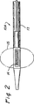
図2、2a、3、3a、3aa、3bおよび11において、典型的なセンサ搭載マッピングカテーテル10aおよび典型的なセンサ搭載血管壁貫通カテーテル10b、10c、10d、10eの詳細な構成を示す。血管壁貫通カテーテル10b、10c、10d、10eは、その全体が参照により本願に明白に援用される、米国特許第5,830,222号、米国特許第6,068,638号、米国特許第6,159,225号、または米国特許第6,071,292号、または同時係属出願の米国特許出願第08/730,324号、米国特許出願第09/117,515号、米国特許出願第08/836,295号、米国特許出願第09/059,532号、米国特許出願第08/837,294号、米国特許出願第09/056,589号、米国特許出願第09/282,276号、米国特許出願第09/282、774号、米国特許出願第09/507,139号、米国特許出願第09/505,149号および/または米国特許出願第09/766,502号に説明されている、血管壁カテーテルの任意のまたは全ての要素を組み込むか、または備え得る。それに加えて、血管壁貫通カテーテル10b、10c、10d、10eは、カテーテル本体上に、特定の長手方向位置および出口孔18に対して特定の回転位置または径方向位置に単に取り付けられた磁場成分センサ棒体14を備え、貫通具20は出口孔18を通ってカテーテル本体から退去する。この磁場成分センサ14は、互いに直交する関係にて構成された複数の磁気コイルを備えることが好ましく、これは参照により本願に明白に援用される。血管壁貫通カテーテル10b、10c、10d、10eが、図11に示すように、ガイドワイヤルーメンを有することが所望される場合は、ガイドワイヤルーメン22はセンサ14に隣接するかまたは隣り合わせて、カテーテル本体内に延びる。しかしながら、別の実施態様では、ガイドワイヤルーメンがカテーテル本体のセンサを通って長手方向
に延び、かつセンサ14に直交して配向された構成要素が、図5に示すようにガイドワイヤルーメンの周囲に配置されることが望ましいと思われる。詳細には、図5は、第一電磁コイル30、第二電磁コイル32、および第三電磁コイル34を備えたセンサ14aを示す。これら3個のコイル30, 32, 34は三角形の形態にて互いに連結されており、従ってガイドワイヤルーメン22はコイルのセンサを通って延び、実質的にセンサ14a内のセンサである。
In this embodiment, two (2)
A vessel
(Catheter with sensor)
2, 2a, 3, 3a, 3aa, 3b and 11 show the detailed configuration of a typical sensor-equipped mapping catheter 10a and typical sensor-equipped vessel wall penetration catheters 10b, 10c, 10d, 10e. The vessel wall penetrating catheters 10b, 10c, 10d, 10e are hereby expressly incorporated by reference in their entirety, US Pat. No. 5,830,222, US Pat. No. 6,068,638, US Pat. , 159,225, or US Pat. No. 6,071,292, or co-pending US patent application Ser. No. 08 / 730,324, US patent application Ser. No. 09 / 117,515, US patent application Ser. No. 836,295, U.S. Patent Application No. 09 / 059,532, U.S. Patent Application No. 08 / 837,294, U.S. Patent Application No. 09 / 056,589, U.S. Patent Application No. 09 / 282,276, U.S. Pat. Patent application 09 / 282,774, US patent application 09 / 507,139, US patent application 09 / 505,149 and / or US patent application 09/7. It is described in US 6,502, or incorporate any or all of the elements of the vessel wall catheters, or may comprise. In addition, the vessel wall penetrating catheters 10b, 10c, 10d, and 10e are magnetic field component sensors that are simply mounted on the catheter body at a specific longitudinal position and a specific rotational or radial position with respect to the
図2は、長尺状の可撓性カテーテル本体17と、同カテーテル本体17の上または内部に取り付けられた、上述の種類のセンサ14とを備えたセンサ搭載マッピングカテーテル10aを示す。マッピングカテーテル10aを血管の管腔内にてセンタリングするために、任意のセンタリングバルーン15を備えていてもよい。このようなカテーテルのセンタリングは、マップされた血管の直径がマッピングカテーテル10aの直径よりも相当大きい場合に特に望ましく、従って、マッピング工程の進行に伴うマッピングカテーテルの側方への移動を防止することが望ましい。任意のセンタリングバルーン15を使用する実施態様において、バルーン15は血管壁の管腔の直径に近い大きさに拡張され得るが、マッピング工程においてオペレータがマッピングカテーテル10aを長手方向に前進または後退することを拒むほど、血管壁と摩擦的に接触するものではない。
FIG. 2 shows a sensor-mounted mapping catheter 10a comprising an elongate
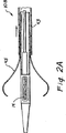
図2aは、長尺状の可撓性カテーテル本体17と、カテーテル本体17の上または内部に取り付けられた、上述の種類のセンサ14を備えたマッピングカテーテル10bの別の実施態様を示す。カテーテル本体17の周囲に、後退可能なシース43が配置されている。複数のセンタリングアーム45が径方向に離間された位置にてカテーテル本体17の周
囲に取り付けられている。シース43が先端方向へ前進されるとき、シースはセンタリングアームを直線形状に圧迫して、カテーテル本体17の外側面に対してセンタリングアームを拘束または保持するであろう。シース43が後退されると、図2aに示すように、センタリングアーム45は外側に跳ね返り湾曲形状になるであろう。この方法において、センタリングアーム45は、カテーテル10aが前進または後退されると同時に血管の内壁に当接し、従ってセンサ14を血管の管腔内のほぼ中心位置に維持して、血管の管腔内におけるセンサ14の径方向または側方の動きから生じる血管マッピングの変化を排除する。
FIG. 2a shows another embodiment of a mapping catheter 10b with an elongate
図3〜3bは、本発明のセンサ搭載組織貫通カテーテルの、数個の異なる実施例を示す。図3の実施例において、センサ14がカテーテルの内部の、貫通具出口孔18の近隣に取り付けられているが、貫通具のハウジングには取り付けられていない。
Figures 3 to 3b show several different embodiments of the sensor loaded tissue penetrating catheter of the present invention. In the embodiment of FIG. 3, the
図3aおよび3aaの実施例において、センサ14はカテーテル内で貫通具出口孔18の基端側に取り付けられており、安定器27によって貫通具ハウジング9に固定されている。貫通具ハウジング9は、金属等の剛性材料で形成されており、安定器27はセンサ14をハウジング9にしっかり取り付けている。図3aaの断面図に示すように、安定器27は、センサ14を、ハウジング9に対して固定距離にて固定間隔を有するように、しっかりと挟むかまたは保持するよう特に構成され得る。この方法では、安定器27は、カテーテルが湾曲あるいは別様に変形する際の、貫通具ハウジング27に対するセンサ14の移動を防止する。この方法において、安定器27は、蛇行した血管、または他の湾曲あるいは狭窄した解剖学的領域にて発生し得る、カテーテル本体のあらゆる湾曲または屈曲に左右されずに、貫通具20の位置に対してセンサの位置をほぼ一定の関係に維持することを確実にする補助となる。
In the embodiment of FIGS. 3 a and 3 aa, the
図3bの実施例は、図3a−3aaに示す実施例と同一のセンサ14およびスタビライザ11の構成を組み込んでいるが、カテーテル10d内に配置された画像装置31をさらに備える。この画像装置31は血管内超音波(IVUS)変換器、ドップラー(Doppler)または任意の他の適切な種類の画像変換器または装置であり得る。画像装置31から患者または患畜の体の外部に配置されたモニタへ画像信号を伝送するために、ワイヤ33または他の連絡が設けられている。この方法において、画像装置31は、カテーテルの先端に隣接するかまたは近隣にある解剖学的構造の画像を提供し得る。この画像は、図8に示し後に説明する血管マップまたはスキャンの画像と連携するか、合成されるか、重ね合わせられて使用され得る。
(センサ塔載カテーテルを使用して実行した二重CABG処置の実施例)
図4に、一つの管状バイパスグラフト40が左乳腺LIMAを左前下行枝冠状動脈LADに連結させて、第二の冠状バイパスグラフト42が下行大動脈を右冠状動脈RCAに連結させる、二重冠状動脈バイパス処置を概略的に示す。管状バイパスグラフト40,42は、上述しかつ図1に概ね図示した経皮的なカテーテルベースの工程により導入される。
The embodiment of FIG. 3b incorporates the
(Example of double CABG procedure performed using sensor mounted catheter)
In FIG. 4, a single coronary
本発明のセンサ搭載血管壁貫通カテーテルは、異なる処置を行うために異なる方法で使用され得る。より詳細には、三通りの一般的なアプローチ、即ちa)一つのセンサが血管壁貫通カテーテルに、他方のセンサがターゲットに配置される二重センサのアプローチと、b)以前にセンサマップした解剖学的領域内の、単一センサのアプローチと、c)二次元または三次元データが以前に得られている解剖学的領域内の、単一センサのアプローチとが採用される。
A.一つのセンサが血管壁貫通カテーテルに、他方のセンサがターゲットに配置される二重センサのアプローチ
本実施態様では、血管壁貫通カテーテル10上に配置されたセンサ14に加えて、内部に血管壁貫通カテーテル10の貫通具20が延びるべき目標位置に配置されている。これら二つのセンサは、その位置をコンピュータにリアルタイアムで(ゲーティングを必要とすることなしに)通信する。目標位置に配置されたセンサは、例えばマッピングカテーテル等のカテーテル上に取り付けられ、同カテーテルは管状構造を通って前進する。この工程は、目標位置が、その内部または上に第二のセンサが配置され得る管状の解剖学的構造(例、血管)または他の解剖学的構造である必要がある。
B. 以前にセンサマッピングされている解剖学的領域内の、単一センサのアプローチ
本実施態様では、マッピングカテーテル上に配置されたセンサを、目的の解剖学的領域内に挿入して、マッピングカテーテルを前進または移動させて、磁場を作動させる。その
結果、目的の解剖学的構造をマップする位置データがコンピュータに提供される。その後、解剖学的構造がマップされた後にマッピングカテーテルを後退し得、上にセンサ14が取り付けられた血管壁貫通カテーテル10を挿入し得る。その後、血管壁貫通カテーテル10のセンサ14からの信号がコンピュータに受信されて、モニタまたはスクリーン上に、以前にマッピングされた解剖学的領域に対して表示されるであろう。この方法では、血管壁貫通カテーテル10は、次に貫通具20が前進されたときに、貫通具20が、以前にマッピングされた解剖学的画像に示されるように、所望の目標位置の中へ延びるように配置および回転配向され得る。目標位置が鼓動している心臓のように動いている場合は、ゲーティングが必要であり得る。
C. 二次元または三次元データが以前に得られている、単一センサのアプローチ
本実施態様では、患者または患畜の体の内部または上に、目標位置に関して決定された位置に一つ以上のセンサが配置される。その後、センサが配置された目標位置の解剖学的領域を、二次元または三次元データを形成可能なスキャン装置を用いてスキャンする。このデータは、目的の解剖学的領域内の組織および解剖学的形態/構造(例、電磁共鳴画像(MRI)、コンピュータX線断層(CT)、スパイラルCT、電子ビームCT、超音波、等)を表す。スキャンが完了した後、患者または患畜を検出フィールド(例、検出工程の実行に必要な磁場または他のエネルギー場を形成する、磁石または外部エネルギー場形成装置に近接した平台上)内に配置する。その上またはその内部にセンサ14が取り付けられた血管壁貫通カテーテル10を挿入し、目的の解剖学的領域へ前進させる。血管壁貫通カテーテルのセンサ14を作動させて、リアルタイムの位置および配向の情報をコンピュータに送ることにより、血管壁貫通カテーテル10の正確な位置および回転配向が測定される。患者または患畜の体の上または内部に配置されている他方のセンサも作動させて、そのセンサもリアルタイムのデータをコンピュータに提供し、コンピュータはこれらのセンサのデータを使用して、以前にスキャンした画像または解剖学的データをセンサ位置に対して配置する。ある用途において、患者または患蓄の体の上または内部に配置されたセンサは撮像可能であるか、または、撮像可能である別のマーカを体の上または内部に配置して、各センサの位置または意図される位置を画像上に表示し得る。
(モニタディスプレイ)
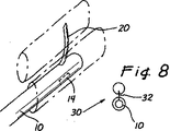
図8に、上記に要約したアプローチのいずれかによって形成され得るモニタディスプレイの例を示す。図8の例には、動脈と、動脈に近接する静脈との三次元的解剖学的構造が示されている。センサ塔載血管壁貫通カテーテル10が動脈内に配置されている。血管壁貫通カテーテル10上のセンサ14は、コンピュータに三次元データを出力する。血管壁貫通カテーテル10の回転配向は、ディスプレイの下部右角内に示す二次元スクリーンの挿入部分30にて表示される。ポインタ32は貫通具20が血管壁貫通カテーテル10から前進するであろう方向を示す。オペレータはディスプレイを観察しながら、血管壁貫通カテーテル10を、センサ14が所望の長手方向位置内に到達するまで前進および/または後退させ得る。その後、オペレータはディスプレイ上で二次元挿入部分30を監視し得、二次元ディスプレイ30上でポインタ32が静脈内に延びるまで、動脈内にて血管壁貫通カテーテル10を回転させ得る。その後、貫通具20を、血管壁貫通カテーテル10から外部へ前進させて、動脈壁と、静脈と任意の動脈との間に位置する任意の組織とを経由して、静脈管内の所望の目標位置へ前進させる。この最初の貫通を達成した後、様々な種類の付加的な工程が実行され得る。ある場合において、貫通具20は内部を通って延びるガイドワイヤルーメンを備え、ガイドワイヤルーメンは貫通具のルーメンを通って、静脈または他の対象の解剖学的構造内へ通過されるであろう。その後、貫通具20を後退させて、ガイドワイヤをその位置に残留させ得る。その後、連結具、グラフト、ステント、ステントグラフト、または他のインプラント装置をガイドワイヤの上部にて前進させて、所望の位置に配置し得る。ある用途、例えば二つの血管壁の間にチャネルが形成されている場合などには、カテーテルベースの血管再生処置(例、PICAB(登録商標)および/またはPICVA(登録商標))で実施されるように、チャネル内に連結具を配置して、血管内に一つ以上の塞栓子を配置することによって、血液が一つの血管から多方の血管へ
と流れるようにし得る。同血管再生処置は、米国特許第5,830,222号、米国特許第6,068,638号、米国特許第6,159,225号、または米国特許第6,071,292号、または米国特許出願第08/730,324号、米国特許出願第09/117,515号、米国特許出願第08/837,294号、米国特許出願第09/056,589号、米国特許出願第09/282276号、米国特許出願第09/282774号、米国特許出願第09/505149号、および/または出願第09/766502号に説明されており、これらの各特許および特許出願はその全体が参照により本願に明白に援用される。
(センサ搭載カテーテルを使用した、経皮的in situ (PICVA(登録商標)処置)
図6および図7に、本発明のセンサ搭載カテーテルを使用して実行される経皮的なin
situによる冠状静脈性動脈化(PICVA(登録商標))処置の例を示す。この処置では、血管2は上述したように、以前に断層撮像されているかまたはセンサ搭載マッピングカテーテルによってマップされている。検出フィールド内に患者または患畜が配置されている間、センサ14を作動させたセンサ塔載血管貫通カテーテル10を血管1内に前進させることによって、血管1の解剖学的構造のマップを形成する。その後、コンピュータは血管1の解剖学的構造を血管2の解剖学的構造と比較して、カテーテルの貫通具20を血管1の管腔から血管2の管腔内に位置する対象部位40内へ貫通させるために、血管壁貫通カテーテル10に取り付けられたセンサ14を、センサ配置部位40に配置するべきかを否かを決定する。センサ14はリアルタイムの位置および回転データをオペレータに提供するので、オペレータはセンサ14が意図されるセンサ配置部位42に配置されるまで、血管壁貫通カテーテル10を前進させることが可能である。その後オペレータは、センサ14の回転配向が、貫通具20が目標位置40に達するのに必要な予め決定されたセンサの所望の回転配向と一致するまで、カテーテル10を回転させ得る。このカテーテル10の回転配向は、図8に示しかつ上述したように、可視回転配向表示装置30の補助により行い得る。血管壁貫通カテーテル10が、そのセンサ14が意図されるセンサ位置42にあり、かつセンサ14の回転配向が、貫通具が正確にターゲット部位40に照準を当てるよう配向された後、貫通具20は、血管壁貫通カテーテル10から外方向に、血管1の壁を経由して、血管1および血管2の間の空間を経由して、任意の血管壁を経由して血管の管腔内の目標位置へと前進されるであろう。その後、貫通具20を通してガイドワイヤを血管2の管腔内へ前進させて、貫通具20を血管壁貫通カテーテル10内へ後退させる。その後、血管壁貫通カテーテル10を患者または患畜の体から除去し得る。その後、貫通具の管路(tract )拡大装置をガイドワイヤの上部において前進させて、貫通具20によって形成された通路を拡大させる。その後、ガイドワイヤの上部において連結具を前進させて、血管1と血管2との間に形成されたチャネル内に配置することにより、血管1および血管2内に形成された開口の近接度を維持して血管1と血管2との間の血流を促進し得る。血管1および/または血管2内に一つ以上の塞栓子を配置することにより、血管1と血管2との間の所望の血流を促進し得る。本目的に使用可能なチャネル拡大装置、塞栓子、連結具装置、および搬送カテーテルの特定の種類は、米国特許第5,830,222号、米国特許第6,068,638号、米国特許第6,159,225号、米国特許第6,071,292号、または同時係属出願の米国特許出願第08/730,327号、米国特許出願第09/117,516号、米国特許出願第08/970,694号、米国特許出願第09/056,589号に説明されており、その全体は参照により本願に明白に援用される。
The sensor-equipped vessel wall penetrating catheter of the present invention can be used in different ways to perform different procedures. More specifically, there are three general approaches: a) a dual sensor approach in which one sensor is placed on the transvascular catheter and the other sensor is placed on the target, and b) a previously sensor mapped anatomy. A single sensor approach within the anatomical region and c) a single sensor approach within the anatomical region from which two-dimensional or three-dimensional data has been previously obtained.
A. Dual sensor approach where one sensor is placed on the vessel wall penetrating catheter and the other sensor is placed on the target. In this embodiment, in addition to the
B. Single sensor approach in an anatomical region that has previously been sensor mapped In this embodiment, a sensor placed on a mapping catheter is inserted into the target anatomical region to provide a mapping catheter. To move forward or move to activate the magnetic field. As a result, location data that maps the desired anatomy is provided to the computer. Thereafter, after the anatomy is mapped, the mapping catheter can be retracted and a vessel
C. two-dimensional or three-dimensional data has been obtained previously, the approach this embodiment a single sensor, the patient or the affected animals body inside or on one or more sensors to determined for the target position position Is placed. Thereafter, the anatomical region of the target position where the sensor is arranged is scanned using a scanning device capable of forming two-dimensional or three-dimensional data. This data includes tissue and anatomy / structure within the intended anatomical region (eg, electromagnetic resonance imaging (MRI), computed X-ray tomography (CT), spiral CT, electron beam CT, ultrasound, etc.) Represents. After the scan is completed, placing the patient or animal subject detection field (eg, a magnetic field or other energy field required to perform the detection process, the magnets or external energy field forming apparatus proximate the upper flatbed) within. A vascular
(Monitor display)
FIG. 8 shows an example of a monitor display that can be formed by any of the approaches summarized above. The example of FIG. 8 shows a three-dimensional anatomical structure of an artery and a vein adjacent to the artery. A sensor-mounted blood vessel
(Percutaneous in situ using a sensor-equipped catheter (PICVA® treatment)
FIGS. 6 and 7 show a percutaneous in operation performed using the sensor-mounted catheter of the present invention.
An example of coronary venous arterialization (PICVA®) treatment with situ is shown. In this procedure, the blood vessel 2 has been previously tomographed or mapped with a sensor-mounted mapping catheter, as described above. By while the patient or animal subject is located, the vessel through the
カテーテルを通して上述のPICVA(登録商標)処置に使用される連結具および/または塞栓子、および他の種類の径方向に拡張可能なインプラント可能装置(例、ステント、ステントグラフト等)を搬送する際には、連結具、塞栓子、ステント、ステントグラフト、または他のインプラント装置を搬送する前に、同搬送カテーテル上にセンサを用いて、搬送カテーテルの所望される配置および回転配向を容易にすることが望ましいと思われる。図9および図10にその例を示す。図9および図10において、開放端と側壁開口部52とを有する一部被覆された連結具50が、連結具搬送カテーテル54内に、径方向に陥没した状態にて配置されている。上述した種類のセンサ14aが搬送カテーテル54の上または内部に、カテーテルに取り付けられた連結デバイス50の回転配向に関して決定された長手方向位置および回転配向にて取り付けられている。血管壁貫通カテーテル10に関して上述した方法では、連結具搬送カテーテル54の正確な長手方向位置および回転配向は、カテーテル54から連結具50を留置する前に決定され得る。搬送カテーテル54の回転配向を正確に決定する能力によって、連結具50が次にカテーテル54から留置されて径方向に解放されたときに、その側部開口部52が患者または患畜の解剖学的構造に対して所望の位置にあるように、連結具50を留置する前に連結具50の側部開口部52を予め配置しておくことが可能となる。これは図10に詳細に示され、ここでは上述しかつ図7、図8および図11に示すように、血管壁貫通カテーテル10を使用して、動脈と静脈との間にチャネルが形成されている。チャネルを拡大した後、内部に径方向に陥没した塞栓子50が配置された図9に示す種類の連結具搬送カテーテル54を、予め配置してあるガイドワイヤの上部にて前進させる。連結具搬送カテーテル54は、センサ14aの長手方向位置が、コンピュータにより決定されかつディスプレイ上で表示されるように、連結具50が以前に形成された静脈と動脈の間のチャネル内に配置され、連結具50の対向する端が各々動脈内および静脈内に配置されたことを示すまで前進させる。その後、センサ14aの回転位置が連結具50の側部開口部が所望の位置の部分内にあることを示すまで、連結具搬送カテーテル54を回転させる。その後、連結具搬送カテーテル54のシース56を基端連結部内に引き込むことによって、径方向に緊縮された連結具50の周囲から制約を解除して連結具50を径方向に拡張させて、図10に示す位置にインプラントさせる。この配置において、動脈内に配置された連結具の端に入り込む動脈血の一部は、側部開口部52を通過して動脈に流れ得るが、それ以外の動脈血は連結具50のルーメン内を分岐して、静脈内に位置する対向側の端から流出するであろう。
(センサ搭載固定可能シース)
図12〜12bは、本発明のセンサ搭載固定可能シース100の実施例を示すものであり、図12cはセンサ搭載固定可能シース100とともに使用可能な、特別にデザインされた貫通カテーテルの断面を示す。
When delivering connectors and / or emboli used in the PICVA® procedure described above and other types of radially expandable implantable devices (eg, stents, stent grafts, etc.) through a catheter It may be desirable to use a sensor on the delivery catheter to facilitate the desired placement and rotational orientation of the delivery catheter prior to delivery of a connector, embolus, stent, stent graft, or other implant device. Seem. An example is shown in FIGS. 9 and 10, a partially covered
(Sensor-mountable sheath)
FIGS. 12-12b illustrate an embodiment of a sensor-mounted
シース100は、ハンドピースまたはハブ102と、先端に近接する側壁内に形成された側部開口部106を有する長尺状の可撓性シース本体104とを備える。側部開口部106の直径の反対側に位置するシース100の側壁上には、固定バルーン108が配置されている。シース本体104の先端部分内には少なくとも一つのセンサ108が取り付けられ、ブラインドルーメン112を通ってワイヤ110が延び、センサを本願の他の場所に説明されている対外検出制御装置に接続する。ここに示す単一センサの実施態様の代わりに、シース本体104内またはシース本体104上の二箇所以上に、二個以上のセンサ108を配置し得ることが理解されよう。ガイドワイヤルーメン114がシース100を通って長手方向に延びて、周知の確立された処置技術に従って、シースをガイドワイヤの上部にて前進させ得る。ワーキングルーメン116は、組織貫通カテーテル120(図12C)等の別個のカテーテルが側部開口部106に隣接する位置までワーキングルーメン116内を前進し得るように、シース本体104を通って少なくとも側部開口部106の
位置まで延びている。ワーキングルーメンは、カテーテル120がワーキングルーメン116内に挿入されているときにカテーテル120が回転しないように、断面が非円形状、キー状、鋸刃状、または別様の形状を有する。
The
一つの作動モードにおいて、センサ搭載シースは血管系を介して、目標位置(例、他の血管のルーメン内の位置、組織、解剖学的構造、腫瘍等の内部の位置)に近接または隣接した位置まで挿入および前進される。上述したこの方法において、センサ108は、シースの側部開口部106が目標位置の方向を向いて整合されるように、シースを長手方向にて配向しかつ回転配向させるように使用され得る。その後、固定バルーン108を膨張させて、シース本体104を、血管内において固定した長手方向位置および回転位置にて固定する。その後、貫通カテーテル120等のカテーテルまたは長尺状の装置をワーキングルーメン116内に周知の回転配向にて挿入する。その後、カテーテル120を、貫通具出口孔(図12cに図示せず)が側部開口部106内に位置するまで前進させる。その後、貫通具20aを、側部開口部106を通って目標位置まで前進させ得る。この方法において、シース100は貫通カテーテル120の特定の位置および配向を誘導するために使用され、貫通カテーテル120は、予め配置および固定されたシース本体104の回転配向に関して決定された回転配向に保持されるため、シースのワーキングルーメン116を回転せずに通って前進される。
In one mode of operation, the sensor-equipped sheath is close to or adjacent to the target location (eg, location within the lumen of another vessel, tissue, anatomy, tumor, etc.) via the vasculature. Until inserted and advanced. In this method described above, the
本発明を上記において、本発明の特定の実施例および実施態様を参照に説明してきたが、本発明に意図される趣旨および範囲から逸脱せずにこれらの実施例および実施態様に様々な追加、削除、変更、および修正が為され得る。例えば、一つの実施態様または実施例の任意の要素または属性は、そうすることにより実施態様または実施例が、その意図される使用法に適さないものとされない限りは、他の実施態様または実施例に組み込むか、またはそれらと伴に使用され得る。同様に、上述した磁気センサおよび関連する装置は、意図される目的に使用可能な他の種類のセンサおよび検出装置(例えば、無線周波、他の磁気センサ、超音波、マイクロ波、光、X線等)と交換または置換えられ得ることを理解されたい。このような適度な追加、削除、変更および改良は、説明した実施例および実施態様の等価物とみなされ、請求の範囲の範疇に含まれるものとする。 While the invention has been described above with reference to specific embodiments and embodiments of the invention, various additions to these embodiments and embodiments have been made without departing from the spirit and scope of the invention. Deletes, changes and modifications can be made. For example, any element or attribute of one embodiment or example may be used unless the embodiment or example does not make it unsuitable for its intended use. Can be incorporated into or used with them. Similarly, the magnetic sensors and associated devices described above are other types of sensor and detection devices (eg, radio frequency, other magnetic sensors, ultrasound, microwaves, light, x-rays) that can be used for the intended purpose. Etc.) and can be replaced or replaced. Such reasonable additions, deletions, modifications and improvements are considered equivalents of the described examples and embodiments and are intended to be within the scope of the claims.
Claims (18)
a)カテーテル本体(17)と、
b)カテーテル本体(17)から径方向へ突出するように前進可能であり、該カテーテル本体(17)が内部に配置されている解剖学的管状構造の壁を外方向へ貫通して目標位置へ達する貫通具(20)と、
c)カテーテル本体(17)上またはカテーテル本体(17)内に前記貫通具に対して周知の位置関係にて配置されている前記センサ(14,14a)と、該センサは検出フィールド内における同センサ(14,14a)の位置および回転方向のうちの少なくとも一方を示す信号を出力することと、前記センサモニタは前記センサから受信する信号に基づいて、組織貫通カテーテル(10,10c,10d,10e)の位置、および、前記カテーテル本体から前記貫通具がその後に前進する予測経路を提供することとを備えることを特徴とする、誘導可能な組織貫通カテーテルシステム。A field generator for generating a detection field around at least a portion of the human or animal subject's body, in inducible tissue penetrating catheter system comprising a sensor monitor for receiving signals from the sensor, tissue penetrating through tissue The catheter (10, 10c, 10d, 10e)
a) the catheter body (17) ;
b) an advanceable so as to protrude from the catheter body (17) in the radial direction, through the wall of the tubular anatomical structure to which the catheter body (17) is disposed inside outward to the target position A penetrating tool (20) to reach,
and c) said sensor being disposed at known positional relationship with respect to said through member to the catheter body (17) or on the catheter body (17) in (14, 14a), the sensor in the sensor is within the detection field And outputting a signal indicating at least one of the position (14, 14a) and the rotation direction, and the sensor monitor based on the signal received from the sensor (10, 10c, 10d, 10e) position, and, said the catheter body through tool is characterized in that it comprises and providing a predicted path for advancing thereafter, inducible tissue penetrating catheter system.
磁気検出フィールドを形成する少なくとも一つの磁気装置と、
超音波検出フィールドを形成する少なくとも一つの超音波発生装置と、
赤外線検出フィールドを生成する少なくとも一つの赤外線装置と、X線フィールドを形成する少なくとも一つのX線装置と、
光エネルギーフィールドを形成する少なくとも一つの発光装置と、マイクロ波フィールドを形成する少なくとも一つのマイクロ波装置と
無線周波フィールドを形成する少なくとも一つの無線周波装置と、
マイクロカレント検出フィールドを生成する少なくとも一つのマイクロカレント装置と、
これらの可能な組み合わせと、
から選択された少なくとも一つの装置を備える請求項1に記載の誘導可能な組織貫通カテーテルシステム。The field generator is
At least one magnetic device forming a magnetic detection field;
At least one ultrasonic generator forming an ultrasonic detection field;
At least one infrared device for generating an infrared detection field; and at least one X-ray device for forming an X-ray field;
At least one light emitting device that forms a light energy field, at least one microwave device that forms a microwave field, and at least one radio frequency device that forms a radio frequency field;
At least one microcurrent device for generating a microcurrent detection field;
With these possible combinations,
The steerable tissue penetrating catheter system of claim 1, comprising at least one device selected from:
Applications Claiming Priority (2)
| Application Number | Priority Date | Filing Date | Title |
|---|---|---|---|
| US26680001P | 2001-02-06 | 2001-02-06 | |
| PCT/US2002/003941 WO2002062265A2 (en) | 2001-02-06 | 2002-02-06 | Methods and apparatus for guided transluminal interventions using vessel wall penetrating catheters and other apparatus |
Publications (3)
| Publication Number | Publication Date |
|---|---|
| JP2004524893A JP2004524893A (en) | 2004-08-19 |
| JP2004524893A5 JP2004524893A5 (en) | 2005-12-22 |
| JP4234994B2 true JP4234994B2 (en) | 2009-03-04 |
Family
ID=28454440
Family Applications (1)
| Application Number | Title | Priority Date | Filing Date |
|---|---|---|---|
| JP2002562274A Expired - Fee Related JP4234994B2 (en) | 2001-02-06 | 2002-02-06 | Guided transluminal intervention using vessel wall penetration catheters and other devices |
Country Status (9)
| Country | Link |
|---|---|
| US (1) | US7966057B2 (en) |
| EP (1) | EP1377335B1 (en) |
| JP (1) | JP4234994B2 (en) |
| AT (1) | ATE375179T1 (en) |
| CA (1) | CA2436166A1 (en) |
| DE (1) | DE60222870T2 (en) |
| IL (1) | IL157120A0 (en) |
| MX (1) | MXPA03007008A (en) |
| WO (1) | WO2002062265A2 (en) |
Families Citing this family (140)
| Publication number | Priority date | Publication date | Assignee | Title |
|---|---|---|---|---|
| US6375615B1 (en) | 1995-10-13 | 2002-04-23 | Transvascular, Inc. | Tissue penetrating catheters having integral imaging transducers and their methods of use |
| US7806829B2 (en) * | 1998-06-30 | 2010-10-05 | St. Jude Medical, Atrial Fibrillation Division, Inc. | System and method for navigating an ultrasound catheter to image a beating heart |
| US7366562B2 (en) * | 2003-10-17 | 2008-04-29 | Medtronic Navigation, Inc. | Method and apparatus for surgical navigation |
| US11331150B2 (en) | 1999-10-28 | 2022-05-17 | Medtronic Navigation, Inc. | Method and apparatus for surgical navigation |
| US8644907B2 (en) | 1999-10-28 | 2014-02-04 | Medtronic Navigaton, Inc. | Method and apparatus for surgical navigation |
| JP4234994B2 (en) | 2001-02-06 | 2009-03-04 | メドトロニック バスキュラー インコーポレイテッド | Guided transluminal intervention using vessel wall penetration catheters and other devices |
| US8214015B2 (en) * | 2001-02-06 | 2012-07-03 | Medtronic Vascular, Inc. | In vivo localization and tracking of tissue penetrating catheters using magnetic resonance imaging |
| ATE504330T1 (en) | 2002-04-11 | 2011-04-15 | Medtronic Vascular Inc | DEVICES FOR TRANSLUMINAL OR TRANSTHORACAL INTERSTITIAL ELECTRODE PLACEMENT |
| US8150495B2 (en) * | 2003-08-11 | 2012-04-03 | Veran Medical Technologies, Inc. | Bodily sealants and methods and apparatus for image-guided delivery of same |
| DE10340544B4 (en) | 2003-09-01 | 2006-08-03 | Siemens Ag | Device for visual support of electrophysiology catheter application in the heart |
| DE10340546B4 (en) * | 2003-09-01 | 2006-04-20 | Siemens Ag | Method and apparatus for visually assisting electrophysiology catheter application in the heart |
| DE102004003166B4 (en) * | 2004-01-21 | 2011-09-15 | Siemens Ag | catheter |
| WO2005079492A2 (en) | 2004-02-17 | 2005-09-01 | Traxtal Technologies Inc. | Method and apparatus for registration, verification, and referencing of internal organs |
| CA2561913A1 (en) * | 2004-03-11 | 2005-09-22 | Medrad, Inc. | Energy assisted medical devices, systems and methods |
| DE102004017834B4 (en) * | 2004-04-13 | 2011-01-27 | Siemens Ag | catheter device |
| DE102004020587B4 (en) | 2004-04-27 | 2016-02-18 | Siemens Aktiengesellschaft | Method and apparatus for visually assisting a catheter electrophysiology application with 2D fluoroscopic images |
| US20050267516A1 (en) * | 2004-06-01 | 2005-12-01 | Farzad Soleimani | Embolic protection device for the prevention of stroke |
| US20060030771A1 (en) * | 2004-08-03 | 2006-02-09 | Lewis Levine | System and method for sensor integration |
| GB0419954D0 (en) | 2004-09-08 | 2004-10-13 | Advotek Medical Devices Ltd | System for directing therapy |
| WO2006031934A2 (en) * | 2004-09-15 | 2006-03-23 | Light Sciences Corporation | Surgical sheath with instrument fixation structures |
| US7722565B2 (en) | 2004-11-05 | 2010-05-25 | Traxtal, Inc. | Access system |
| US7751868B2 (en) | 2004-11-12 | 2010-07-06 | Philips Electronics Ltd | Integrated skin-mounted multifunction device for use in image-guided surgery |
| US7805269B2 (en) | 2004-11-12 | 2010-09-28 | Philips Electronics Ltd | Device and method for ensuring the accuracy of a tracking device in a volume |
| EP1838378B1 (en) | 2005-01-18 | 2017-03-22 | Philips Electronics LTD | Apparatus for guiding an instrument to a target in the lung |
| US7840254B2 (en) | 2005-01-18 | 2010-11-23 | Philips Electronics Ltd | Electromagnetically tracked K-wire device |
| WO2008045016A2 (en) | 2005-06-21 | 2008-04-17 | Traxtal Inc. | Device and method for a trackable ultrasound |
| EP1898775B1 (en) | 2005-06-21 | 2013-02-13 | Philips Electronics LTD | System and apparatus for navigated therapy and diagnosis |
| EP1924197B1 (en) | 2005-08-24 | 2017-10-11 | Philips Electronics LTD | System for navigated flexible endoscopy |
| US8784336B2 (en) | 2005-08-24 | 2014-07-22 | C. R. Bard, Inc. | Stylet apparatuses and methods of manufacture |
| US20100218140A1 (en) * | 2005-09-08 | 2010-08-26 | Feke Gilbert D | Graphical user interface for multi-modal images at incremental angular displacements |
| AU2006302057B2 (en) | 2005-10-11 | 2013-03-21 | Carnegie Mellon University | Sensor guided catheter navigation system |
| GB0607761D0 (en) | 2006-04-20 | 2006-05-31 | Site Specific Therapies Ltd | Variable density stent |
| US20130190676A1 (en) | 2006-04-20 | 2013-07-25 | Limflow Gmbh | Devices and methods for fluid flow through body passages |
| US7734341B2 (en) * | 2006-06-06 | 2010-06-08 | Cardiac Pacemakers, Inc. | Method and apparatus for gastrointestinal stimulation via the lymphatic system |
| US20070282376A1 (en) | 2006-06-06 | 2007-12-06 | Shuros Allan C | Method and apparatus for neural stimulation via the lymphatic system |
| WO2007146880A2 (en) * | 2006-06-09 | 2007-12-21 | Traxtal Inc. | System for image-guided endovascular prosthesis and method for using same |
| US8905999B2 (en) * | 2006-09-01 | 2014-12-09 | Cardiac Pacemakers, Inc. | Method and apparatus for endolymphatic drug delivery |
| US7794407B2 (en) | 2006-10-23 | 2010-09-14 | Bard Access Systems, Inc. | Method of locating the tip of a central venous catheter |
| US8388546B2 (en) | 2006-10-23 | 2013-03-05 | Bard Access Systems, Inc. | Method of locating the tip of a central venous catheter |
| EP2134403B1 (en) * | 2007-04-11 | 2012-12-12 | Elcam Medical Agricultural Cooperative Association Ltd. | System for accurate placement of a catheter tip in a patient |
| ITTO20070824A1 (en) * | 2007-11-15 | 2009-05-16 | Consiglio Nazionale Ricerche | OCCLUSION SYSTEM OF BLOOD VASES |
| US8781555B2 (en) | 2007-11-26 | 2014-07-15 | C. R. Bard, Inc. | System for placement of a catheter including a signal-generating stylet |
| ES2465915T3 (en) | 2007-11-26 | 2014-06-09 | C.R. Bard, Inc. | Integrated system for intravascular catheter placement |
| US10751509B2 (en) | 2007-11-26 | 2020-08-25 | C. R. Bard, Inc. | Iconic representations for guidance of an indwelling medical device |
| US10449330B2 (en) | 2007-11-26 | 2019-10-22 | C. R. Bard, Inc. | Magnetic element-equipped needle assemblies |
| US9649048B2 (en) | 2007-11-26 | 2017-05-16 | C. R. Bard, Inc. | Systems and methods for breaching a sterile field for intravascular placement of a catheter |
| US10524691B2 (en) | 2007-11-26 | 2020-01-07 | C. R. Bard, Inc. | Needle assembly including an aligned magnetic element |
| US9521961B2 (en) | 2007-11-26 | 2016-12-20 | C. R. Bard, Inc. | Systems and methods for guiding a medical instrument |
| US8849382B2 (en) | 2007-11-26 | 2014-09-30 | C. R. Bard, Inc. | Apparatus and display methods relating to intravascular placement of a catheter |
| US20090287120A1 (en) | 2007-12-18 | 2009-11-19 | Searete Llc, A Limited Liability Corporation Of The State Of Delaware | Circulatory monitoring systems and methods |
| US8636670B2 (en) | 2008-05-13 | 2014-01-28 | The Invention Science Fund I, Llc | Circulatory monitoring systems and methods |
| US9672471B2 (en) | 2007-12-18 | 2017-06-06 | Gearbox Llc | Systems, devices, and methods for detecting occlusions in a biological subject including spectral learning |
| US8280484B2 (en) | 2007-12-18 | 2012-10-02 | The Invention Science Fund I, Llc | System, devices, and methods for detecting occlusions in a biological subject |
| US20090287094A1 (en) * | 2008-05-15 | 2009-11-19 | Seacrete Llc, A Limited Liability Corporation Of The State Of Delaware | Circulatory monitoring systems and methods |
| US9717896B2 (en) | 2007-12-18 | 2017-08-01 | Gearbox, Llc | Treatment indications informed by a priori implant information |
| US8478382B2 (en) | 2008-02-11 | 2013-07-02 | C. R. Bard, Inc. | Systems and methods for positioning a catheter |
| US8374680B2 (en) * | 2008-04-21 | 2013-02-12 | Medtronic Vascular, Inc. | Needleless catheters and methods for true lumen re-entry in treatment of chronic total occlusions and other disorders |
| EP2313143B1 (en) | 2008-08-22 | 2014-09-24 | C.R. Bard, Inc. | Catheter assembly including ecg sensor and magnetic assemblies |
| US8437833B2 (en) | 2008-10-07 | 2013-05-07 | Bard Access Systems, Inc. | Percutaneous magnetic gastrostomy |
| WO2010065786A1 (en) * | 2008-12-03 | 2010-06-10 | St. Jude Medical, Atrial Fibrillation Division, Inc. | System and method for determining the positioin of the tip of a medical catheter within the body of a patient |
| US20100191168A1 (en) | 2009-01-29 | 2010-07-29 | Trustees Of Tufts College | Endovascular cerebrospinal fluid shunt |
| US8632468B2 (en) | 2009-02-25 | 2014-01-21 | Koninklijke Philips N.V. | Method, system and devices for transjugular intrahepatic portosystemic shunt (TIPS) procedures |
| US20100305428A1 (en) * | 2009-05-29 | 2010-12-02 | Medtronic, Inc. | Ultrasonic guidance of subcutaneous tunneling |
| RU2691318C2 (en) | 2009-06-12 | 2019-06-11 | Бард Аксесс Системс, Инк. | Method for positioning catheter end |
| US9532724B2 (en) | 2009-06-12 | 2017-01-03 | Bard Access Systems, Inc. | Apparatus and method for catheter navigation using endovascular energy mapping |
| WO2011019760A2 (en) | 2009-08-10 | 2011-02-17 | Romedex International Srl | Devices and methods for endovascular electrography |
| EP2482719A4 (en) | 2009-09-29 | 2016-03-09 | Bard Inc C R | Stylets for use with apparatus for intravascular placement of a catheter |
| US11103213B2 (en) | 2009-10-08 | 2021-08-31 | C. R. Bard, Inc. | Spacers for use with an ultrasound probe |
| US8409098B2 (en) * | 2009-10-14 | 2013-04-02 | St. Jude Medical, Atrial Fibrillation Division, Inc. | Method and apparatus for collection of cardiac geometry based on optical or magnetic tracking |
| US20110103655A1 (en) * | 2009-11-03 | 2011-05-05 | Young Warren G | Fundus information processing apparatus and fundus information processing method |
| CN102821679B (en) | 2010-02-02 | 2016-04-27 | C·R·巴德股份有限公司 | For the apparatus and method that catheter navigation and end are located |
| EP2912999B1 (en) | 2010-05-28 | 2022-06-29 | C. R. Bard, Inc. | Apparatus for use with needle insertion guidance system |
| CN103037761B (en) | 2010-05-28 | 2016-11-02 | C·R·巴德股份有限公司 | Insertion for pin and medical components guides system |
| US9307927B2 (en) | 2010-08-05 | 2016-04-12 | Biosense Webster (Israel) Ltd. | Catheter entanglement indication |
| WO2012021542A2 (en) | 2010-08-09 | 2012-02-16 | C.R. Bard, Inc. | Support and cover structures for an ultrasound probe head |
| BR112013002431B1 (en) | 2010-08-20 | 2021-06-29 | C.R. Bard, Inc | SYSTEM FOR RECONFIRMING THE POSITION OF A CATHETER INSIDE A PATIENT |
| WO2012058461A1 (en) | 2010-10-29 | 2012-05-03 | C.R.Bard, Inc. | Bioimpedance-assisted placement of a medical device |
| CN103260541B (en) | 2010-12-09 | 2016-12-07 | 皇家飞利浦电子股份有限公司 | The computer tomography (CT) that intervention device activates |
| US20120197086A1 (en) * | 2011-01-31 | 2012-08-02 | Nellcor Puritan Bennett Llc | Medical visualization technique and apparatus |
| BR112013030348A2 (en) | 2011-07-06 | 2017-08-01 | Bard Inc C R | method for determining a length of a medical component for use with an ultrasound imaging system including a probe; method for determining a needle length by a needle guidance system; and needle length determination system for an ultrasound imaging device including an ultrasound probe |
| USD699359S1 (en) | 2011-08-09 | 2014-02-11 | C. R. Bard, Inc. | Ultrasound probe head |
| USD724745S1 (en) | 2011-08-09 | 2015-03-17 | C. R. Bard, Inc. | Cap for an ultrasound probe |
| WO2013029669A1 (en) | 2011-08-31 | 2013-03-07 | St. Jude Medical Ab | Physiologically adapted cardiac resynchronization therapy |
| PL2939601T3 (en) | 2011-09-06 | 2019-04-30 | Ezono Ag | Magnetic medical device |
| US20130303944A1 (en) | 2012-05-14 | 2013-11-14 | Intuitive Surgical Operations, Inc. | Off-axis electromagnetic sensor |
| US9452276B2 (en) | 2011-10-14 | 2016-09-27 | Intuitive Surgical Operations, Inc. | Catheter with removable vision probe |
| US10238837B2 (en) | 2011-10-14 | 2019-03-26 | Intuitive Surgical Operations, Inc. | Catheters with control modes for interchangeable probes |
| WO2013070775A1 (en) | 2011-11-07 | 2013-05-16 | C.R. Bard, Inc | Ruggedized ultrasound hydrogel insert |
| US8876726B2 (en) | 2011-12-08 | 2014-11-04 | Biosense Webster (Israel) Ltd. | Prevention of incorrect catheter rotation |
| US10213187B1 (en) * | 2012-01-25 | 2019-02-26 | Mubin I. Syed | Method and apparatus for percutaneous superficial temporal artery access for carotid artery stenting |
| EP2861153A4 (en) | 2012-06-15 | 2016-10-19 | Bard Inc C R | Apparatus and methods for detection of a removable cap on an ultrasound probe |
| WO2014022556A1 (en) | 2012-08-02 | 2014-02-06 | Volcano Corporation | Method for seam elimination and reconstruction of coplanar images from intravascular ultrasonic data |
| US9414752B2 (en) | 2012-11-09 | 2016-08-16 | Elwha Llc | Embolism deflector |
| US10639179B2 (en) | 2012-11-21 | 2020-05-05 | Ram Medical Innovations, Llc | System for the intravascular placement of a medical device |
| US10588586B2 (en) | 2013-01-16 | 2020-03-17 | Siemens Healthcare Gmbh | Cardiac analysis based on vessel characteristics |
| US9257220B2 (en) | 2013-03-05 | 2016-02-09 | Ezono Ag | Magnetization device and method |
| GB201303917D0 (en) | 2013-03-05 | 2013-04-17 | Ezono Ag | System for image guided procedure |
| US9459087B2 (en) | 2013-03-05 | 2016-10-04 | Ezono Ag | Magnetic position detection system |
| US10835367B2 (en) | 2013-03-08 | 2020-11-17 | Limflow Gmbh | Devices for fluid flow through body passages |
| CN107432762B (en) | 2013-03-08 | 2021-04-13 | 林弗洛公司 | Methods and systems for providing or maintaining fluid flow through a body passageway |
| US9737696B2 (en) | 2014-01-15 | 2017-08-22 | Tufts Medical Center, Inc. | Endovascular cerebrospinal fluid shunt |
| EP3998100A1 (en) | 2014-01-15 | 2022-05-18 | Tufts Medical Center, Inc. | Endovascular cerebrospinal fluid shunt system |
| US9839372B2 (en) | 2014-02-06 | 2017-12-12 | C. R. Bard, Inc. | Systems and methods for guidance and placement of an intravascular device |
| US9545263B2 (en) | 2014-06-19 | 2017-01-17 | Limflow Gmbh | Devices and methods for treating lower extremity vasculature |
| WO2016070147A1 (en) | 2014-10-31 | 2016-05-06 | Cerevasc, Llc | Methods and systems for treating hydrocephalus |
| US10973584B2 (en) | 2015-01-19 | 2021-04-13 | Bard Access Systems, Inc. | Device and method for vascular access |
| US10376308B2 (en) | 2015-02-05 | 2019-08-13 | Axon Therapies, Inc. | Devices and methods for treatment of heart failure by splanchnic nerve ablation |
| CA3222892A1 (en) * | 2015-03-10 | 2016-09-15 | Stent Tek Limited | Surgical system, device and methods of use thereof for the percutaneous creation of an arteriovenous fistula (avf) |
| US9636244B2 (en) | 2015-04-09 | 2017-05-02 | Mubin I. Syed | Apparatus and method for proximal to distal stent deployment |
| US10349890B2 (en) | 2015-06-26 | 2019-07-16 | C. R. Bard, Inc. | Connector interface for ECG-based catheter positioning system |
| US20190015127A1 (en) * | 2015-09-23 | 2019-01-17 | Gyrus Acmi, Inc. D/B/A Olympus Surgical Technologies America | Blade positioning system |
| US10327929B2 (en) | 2015-10-30 | 2019-06-25 | Ram Medical Innovations, Llc | Apparatus and method for stabilization of procedural catheter in tortuous vessels |
| US10779976B2 (en) | 2015-10-30 | 2020-09-22 | Ram Medical Innovations, Llc | Apparatus and method for stabilization of procedural catheter in tortuous vessels |
| US10492936B2 (en) | 2015-10-30 | 2019-12-03 | Ram Medical Innovations, Llc | Apparatus and method for improved access of procedural catheter in tortuous vessels |
| US9980838B2 (en) | 2015-10-30 | 2018-05-29 | Ram Medical Innovations Llc | Apparatus and method for a bifurcated catheter for use in hostile aortic arches |
| US10272230B2 (en) | 2015-10-30 | 2019-04-30 | Cerevasc, Llc | Systems and methods for treating hydrocephalus |
| US11020256B2 (en) | 2015-10-30 | 2021-06-01 | Ram Medical Innovations, Inc. | Bifurcated “Y” anchor support for coronary interventions |
| US11000207B2 (en) | 2016-01-29 | 2021-05-11 | C. R. Bard, Inc. | Multiple coil system for tracking a medical device |
| US10173031B2 (en) | 2016-06-20 | 2019-01-08 | Mubin I. Syed | Interchangeable flush/selective catheter |
| CA3031766A1 (en) | 2016-07-29 | 2018-02-01 | Howard Levin | Devices, systems, and methods for treatment of heart failure by splanchnic nerve ablation |
| EP3375399B1 (en) | 2016-10-05 | 2022-05-25 | NuVasive, Inc. | Surgical navigation system |
| EP3609415B1 (en) | 2017-04-10 | 2023-08-23 | LimFlow GmbH | Devices for treating lower extremity vasculature |
| EP3482684A1 (en) * | 2017-11-09 | 2019-05-15 | Koninklijke Philips N.V. | Blood oxygenation measurement and display in mr-guided catheterizations |
| US10561461B2 (en) | 2017-12-17 | 2020-02-18 | Axon Therapies, Inc. | Methods and devices for endovascular ablation of a splanchnic nerve |
| EP3743147B1 (en) * | 2018-01-26 | 2024-04-10 | Axon Therapies, Inc. | Device for endovascular ablation of a splanchnic nerve |
| US20190239764A1 (en) * | 2018-02-07 | 2019-08-08 | Boston Scientific Scimed Inc. | System and method for mapping and characterizing the coronary vasculature for epicardial ablations |
| US10857014B2 (en) | 2018-02-18 | 2020-12-08 | Ram Medical Innovations, Llc | Modified fixed flat wire bifurcated catheter and its application in lower extremity interventions |
| WO2019173784A1 (en) | 2018-03-08 | 2019-09-12 | Cerevasc, Llc | Systems and methods for minimally invasive drug delivery to a subarachnoid space |
| CN111989061A (en) | 2018-04-13 | 2020-11-24 | 卡尔史托斯两合公司 | Guidance system, method and device thereof |
| CA3112353A1 (en) | 2018-10-09 | 2020-04-16 | Limflow Gmbh | Devices and methods for catheter alignment |
| EP3852622A1 (en) | 2018-10-16 | 2021-07-28 | Bard Access Systems, Inc. | Safety-equipped connection systems and methods thereof for establishing electrical connections |
| US11259834B2 (en) * | 2018-10-30 | 2022-03-01 | Biosense Webster (Israel) Ltd. | Brain aneurysm tool with a wire deflection mechanism |
| US20220280244A1 (en) * | 2019-05-31 | 2022-09-08 | Tva Medical, Inc. | Systems, methods, and catheters for endovascular treatment of a blood vessel |
| CN113825464A (en) | 2019-06-20 | 2021-12-21 | 阿克松疗法公司 | Method and apparatus for intravascular ablation of visceral nerves |
| US11612440B2 (en) | 2019-09-05 | 2023-03-28 | Nuvasive, Inc. | Surgical instrument tracking devices and related methods |
| CA3153757A1 (en) | 2019-11-01 | 2021-05-06 | Limflow Gmbh | Devices and methods for increasing blood perfusion to a distal extremity |
| WO2021146724A1 (en) | 2020-01-17 | 2021-07-22 | Axon Therapies, Inc. | Methods and devices for endovascular ablation of a splanchnic nerve |
| BR112022022176A2 (en) * | 2020-06-17 | 2022-12-27 | Boston Scient Medical Device Limited | ELECTROANATOMIC MAPPING SYSTEM |
| CN114027843B (en) * | 2022-01-07 | 2022-04-22 | 诺尔医疗(深圳)有限公司 | Implant device |
| WO2024097275A1 (en) * | 2022-11-01 | 2024-05-10 | Spectrawave | Controlling generation or output of an electromagnetic radiation |
Family Cites Families (25)
| Publication number | Priority date | Publication date | Assignee | Title |
|---|---|---|---|---|
| US5542915A (en) * | 1992-08-12 | 1996-08-06 | Vidamed, Inc. | Thermal mapping catheter with ultrasound probe |
| EP0706345B1 (en) * | 1993-07-01 | 2003-02-19 | Boston Scientific Limited | Imaging, electrical potential sensing, and ablation catheters |
| US6285898B1 (en) * | 1993-07-20 | 2001-09-04 | Biosense, Inc. | Cardiac electromechanics |
| US6690963B2 (en) * | 1995-01-24 | 2004-02-10 | Biosense, Inc. | System for determining the location and orientation of an invasive medical instrument |
| US6302875B1 (en) * | 1996-10-11 | 2001-10-16 | Transvascular, Inc. | Catheters and related devices for forming passageways between blood vessels or other anatomical structures |
| ATE275880T1 (en) | 1995-10-13 | 2004-10-15 | Transvascular Inc | DEVICE FOR BYPASSING ARTERIAL Narrowings AND/OR FOR PERFORMING OTHER TRANSVASCULAR PROCEDURES |
| IL125259A (en) * | 1996-01-08 | 2002-12-01 | Biosense Inc | Apparatus for myocardial revascularization |
| US6915149B2 (en) * | 1996-01-08 | 2005-07-05 | Biosense, Inc. | Method of pacing a heart using implantable device |
| JP3930052B2 (en) * | 1996-02-15 | 2007-06-13 | バイオセンス・インコーポレイテッド | Catheter-based surgery |
| CA2246284C (en) * | 1996-02-15 | 2008-01-29 | Biosense, Inc. | Catheter with lumen |
| EP0910300B1 (en) * | 1996-02-15 | 2003-12-03 | Biosense, Inc. | Site marking probe |
| US6058323A (en) * | 1996-11-05 | 2000-05-02 | Lemelson; Jerome | System and method for treating select tissue in a living being |
| US5845646A (en) * | 1996-11-05 | 1998-12-08 | Lemelson; Jerome | System and method for treating select tissue in a living being |
| US5968053A (en) * | 1997-01-31 | 1999-10-19 | Cardiac Assist Technologies, Inc. | Method and apparatus for implanting a graft in a vessel of a patient |
| EP1009467A4 (en) * | 1997-02-19 | 2001-07-25 | Condado Med Devices Corp | Multi-purpose catheters, catheter systems, and radiation treatment |
| DE69838526T2 (en) * | 1998-02-05 | 2008-07-03 | Biosense Webster, Inc., Diamond Bar | Device for releasing a drug in the heart |
| US20030129750A1 (en) * | 1998-02-05 | 2003-07-10 | Yitzhack Schwartz | Homing of donor cells to a target zone in tissue using active therapeutics or substances |
| US20030125615A1 (en) * | 1998-02-05 | 2003-07-03 | Yitzhack Schwartz | Homing of autologous cells to a target zone in tissue using active therapeutics or substances |
| US7524289B2 (en) * | 1999-01-25 | 2009-04-28 | Lenker Jay A | Resolution optical and ultrasound devices for imaging and treatment of body lumens |
| US6592526B1 (en) * | 1999-01-25 | 2003-07-15 | Jay Alan Lenker | Resolution ultrasound devices for imaging and treatment of body lumens |
| US7769420B2 (en) * | 2000-05-15 | 2010-08-03 | Silver James H | Sensors for detecting substances indicative of stroke, ischemia, or myocardial infarction |
| JP4234994B2 (en) | 2001-02-06 | 2009-03-04 | メドトロニック バスキュラー インコーポレイテッド | Guided transluminal intervention using vessel wall penetration catheters and other devices |
| US7306593B2 (en) * | 2002-10-21 | 2007-12-11 | Biosense, Inc. | Prediction and assessment of ablation of cardiac tissue |
| US7697972B2 (en) * | 2002-11-19 | 2010-04-13 | Medtronic Navigation, Inc. | Navigation system for cardiac therapies |
| WO2004068947A2 (en) | 2003-02-03 | 2004-08-19 | Johns Hopkins University | Active mri intramyocardial injection catheter with deflectable distal section |
-
2002
- 2002-02-06 JP JP2002562274A patent/JP4234994B2/en not_active Expired - Fee Related
- 2002-02-06 DE DE60222870T patent/DE60222870T2/en not_active Expired - Lifetime
- 2002-02-06 EP EP02707755A patent/EP1377335B1/en not_active Expired - Lifetime
- 2002-02-06 IL IL15712002A patent/IL157120A0/en unknown
- 2002-02-06 WO PCT/US2002/003941 patent/WO2002062265A2/en active IP Right Grant
- 2002-02-06 AT AT02707755T patent/ATE375179T1/en not_active IP Right Cessation
- 2002-02-06 CA CA002436166A patent/CA2436166A1/en not_active Abandoned
- 2002-02-06 MX MXPA03007008A patent/MXPA03007008A/en unknown
- 2002-02-06 US US10/467,274 patent/US7966057B2/en active Active
Also Published As
| Publication number | Publication date |
|---|---|
| ATE375179T1 (en) | 2007-10-15 |
| MXPA03007008A (en) | 2004-10-15 |
| DE60222870D1 (en) | 2007-11-22 |
| EP1377335A4 (en) | 2006-03-08 |
| WO2002062265A3 (en) | 2003-10-02 |
| US7966057B2 (en) | 2011-06-21 |
| IL157120A0 (en) | 2004-02-08 |
| WO2002062265A2 (en) | 2002-08-15 |
| EP1377335A2 (en) | 2004-01-07 |
| JP2004524893A (en) | 2004-08-19 |
| EP1377335B1 (en) | 2007-10-10 |
| DE60222870T2 (en) | 2008-05-15 |
| CA2436166A1 (en) | 2002-08-15 |
| US20040147837A1 (en) | 2004-07-29 |
Similar Documents
| Publication | Publication Date | Title |
|---|---|---|
| JP4234994B2 (en) | Guided transluminal intervention using vessel wall penetration catheters and other devices | |
| US8473030B2 (en) | Vessel position and configuration imaging apparatus and methods | |
| US6332089B1 (en) | Medical procedures and apparatus using intrabody probes | |
| US10582879B2 (en) | Method and apparatus for registration, verification and referencing of internal organs | |
| US20190209047A1 (en) | Devices, systems and methods for enhanced visualization of the anatomy of a patient | |
| EP1799103B1 (en) | Delivering a medical device to a selected position within a lumen | |
| US8442618B2 (en) | Method and system for delivering a medical device to a selected position within a lumen | |
| EP2737869A1 (en) | Location sensing using a local coordinate system | |
| CN103417184A (en) | Endobronchial catheter | |
| US20090259296A1 (en) | Gate Cannulation Apparatus and Methods | |
| JP2003299634A (en) | Wireless position sensor | |
| EP1585434B1 (en) | System for mounting an mps sensor on a catheter | |
| AU2002242144A1 (en) | Methods and apparatus for guided transluminal interventions using vessel wall penetrating catheters and other apparatus | |
| JPH11313894A (en) | Stent guide arrangement | |
| CN116437852A (en) | Catheter, catheter system and treatment system for determining parameters during a tissue penetration process | |
| IL168153A (en) | Method and system for mounting an mps sensor on a catheter |
Legal Events
| Date | Code | Title | Description |
|---|---|---|---|
| A521 | Request for written amendment filed |
Free format text: JAPANESE INTERMEDIATE CODE: A523 Effective date: 20050207 |
|
| A621 | Written request for application examination |
Free format text: JAPANESE INTERMEDIATE CODE: A621 Effective date: 20050207 |
|
| A711 | Notification of change in applicant |
Free format text: JAPANESE INTERMEDIATE CODE: A711 Effective date: 20070801 |
|
| A131 | Notification of reasons for refusal |
Free format text: JAPANESE INTERMEDIATE CODE: A131 Effective date: 20080513 |
|
| A601 | Written request for extension of time |
Free format text: JAPANESE INTERMEDIATE CODE: A601 Effective date: 20080808 |
|
| RD02 | Notification of acceptance of power of attorney |
Free format text: JAPANESE INTERMEDIATE CODE: A7422 Effective date: 20080808 |
|
| RD04 | Notification of resignation of power of attorney |
Free format text: JAPANESE INTERMEDIATE CODE: A7424 Effective date: 20080808 |
|
| A602 | Written permission of extension of time |
Free format text: JAPANESE INTERMEDIATE CODE: A602 Effective date: 20080815 |
|
| A601 | Written request for extension of time |
Free format text: JAPANESE INTERMEDIATE CODE: A601 Effective date: 20080912 |
|
| A602 | Written permission of extension of time |
Free format text: JAPANESE INTERMEDIATE CODE: A602 Effective date: 20080922 |
|
| A601 | Written request for extension of time |
Free format text: JAPANESE INTERMEDIATE CODE: A601 Effective date: 20081014 |
|
| A602 | Written permission of extension of time |
Free format text: JAPANESE INTERMEDIATE CODE: A602 Effective date: 20081021 |
|
| A521 | Request for written amendment filed |
Free format text: JAPANESE INTERMEDIATE CODE: A523 Effective date: 20081112 |
|
| TRDD | Decision of grant or rejection written | ||
| A01 | Written decision to grant a patent or to grant a registration (utility model) |
Free format text: JAPANESE INTERMEDIATE CODE: A01 Effective date: 20081209 |
|
| A01 | Written decision to grant a patent or to grant a registration (utility model) |
Free format text: JAPANESE INTERMEDIATE CODE: A01 |
|
| A61 | First payment of annual fees (during grant procedure) |
Free format text: JAPANESE INTERMEDIATE CODE: A61 Effective date: 20081212 |
|
| FPAY | Renewal fee payment (event date is renewal date of database) |
Free format text: PAYMENT UNTIL: 20111219 Year of fee payment: 3 |
|
| R150 | Certificate of patent or registration of utility model |
Ref document number: 4234994 Country of ref document: JP Free format text: JAPANESE INTERMEDIATE CODE: R150 Free format text: JAPANESE INTERMEDIATE CODE: R150 |
|
| FPAY | Renewal fee payment (event date is renewal date of database) |
Free format text: PAYMENT UNTIL: 20111219 Year of fee payment: 3 |
|
| RD02 | Notification of acceptance of power of attorney |
Free format text: JAPANESE INTERMEDIATE CODE: R3D02 |
|
| RD04 | Notification of resignation of power of attorney |
Free format text: JAPANESE INTERMEDIATE CODE: R3D04 |
|
| FPAY | Renewal fee payment (event date is renewal date of database) |
Free format text: PAYMENT UNTIL: 20121219 Year of fee payment: 4 |
|
| R250 | Receipt of annual fees |
Free format text: JAPANESE INTERMEDIATE CODE: R250 |
|
| FPAY | Renewal fee payment (event date is renewal date of database) |
Free format text: PAYMENT UNTIL: 20121219 Year of fee payment: 4 |
|
| FPAY | Renewal fee payment (event date is renewal date of database) |
Free format text: PAYMENT UNTIL: 20131219 Year of fee payment: 5 |
|
| R250 | Receipt of annual fees |
Free format text: JAPANESE INTERMEDIATE CODE: R250 |
|
| R250 | Receipt of annual fees |
Free format text: JAPANESE INTERMEDIATE CODE: R250 |
|
| R250 | Receipt of annual fees |
Free format text: JAPANESE INTERMEDIATE CODE: R250 |
|
| R250 | Receipt of annual fees |
Free format text: JAPANESE INTERMEDIATE CODE: R250 |
|
| R250 | Receipt of annual fees |
Free format text: JAPANESE INTERMEDIATE CODE: R250 |
|
| R250 | Receipt of annual fees |
Free format text: JAPANESE INTERMEDIATE CODE: R250 |
|
| R250 | Receipt of annual fees |
Free format text: JAPANESE INTERMEDIATE CODE: R250 |
|
| R250 | Receipt of annual fees |
Free format text: JAPANESE INTERMEDIATE CODE: R250 |
|
| LAPS | Cancellation because of no payment of annual fees |